Power Supplies in Accelerators - The Cockcroft Institute Marks; ASTeC, CI. Power Supplies in...
54
Neil Marks; ASTeC, CI. Power Supplies in Accelerators, Spring term 2012 Power Supplies in Accelerators Neil Marks, ASTeC, Cockcroft Institute, Daresbury, Warrington WA4 4AD, [email protected] Tel: (44) (0)1925 603191 Fax: (44) (0)1925 603192
Transcript of Power Supplies in Accelerators - The Cockcroft Institute Marks; ASTeC, CI. Power Supplies in...

Neil Marks; ASTeC, CI. Power Supplies in Accelerators, Spring term 2012
Power Supplies in Accelerators
Neil Marks,
ASTeC, Cockcroft Institute,
Daresbury,
Warrington WA4 4AD, [email protected]
Tel: (44) (0)1925 603191
Fax: (44) (0)1925 603192

Neil Marks; ASTeC, CI. Power Supplies in Accelerators, Spring term 2012
Contents
1. Basic elements of power supplies.
2. D.C. supplies:
i) simple rectification with diodes;
ii) phase controlled rectifiers;
iii) ‘other’ conventional d.c. systems;
iv) switch mode systems.
2. Cycling converters:
i) accelerator requirements – energy storage;
– waveform criteria;
ii) slow cycling systems;
iii) fast cycling systems;
iv) switch-mode systems with capacitor storage.

Neil Marks; ASTeC, CI. Power Supplies in Accelerators, Spring term 2012
Basic components – structure.
LOAD switch-gear
transformer
rectifier/
switch
regulation
(level setting)
smoothing
monitoring
Neil Marks; ASTeC, CI. Power Supplies in Accelerators, Spring term 2012
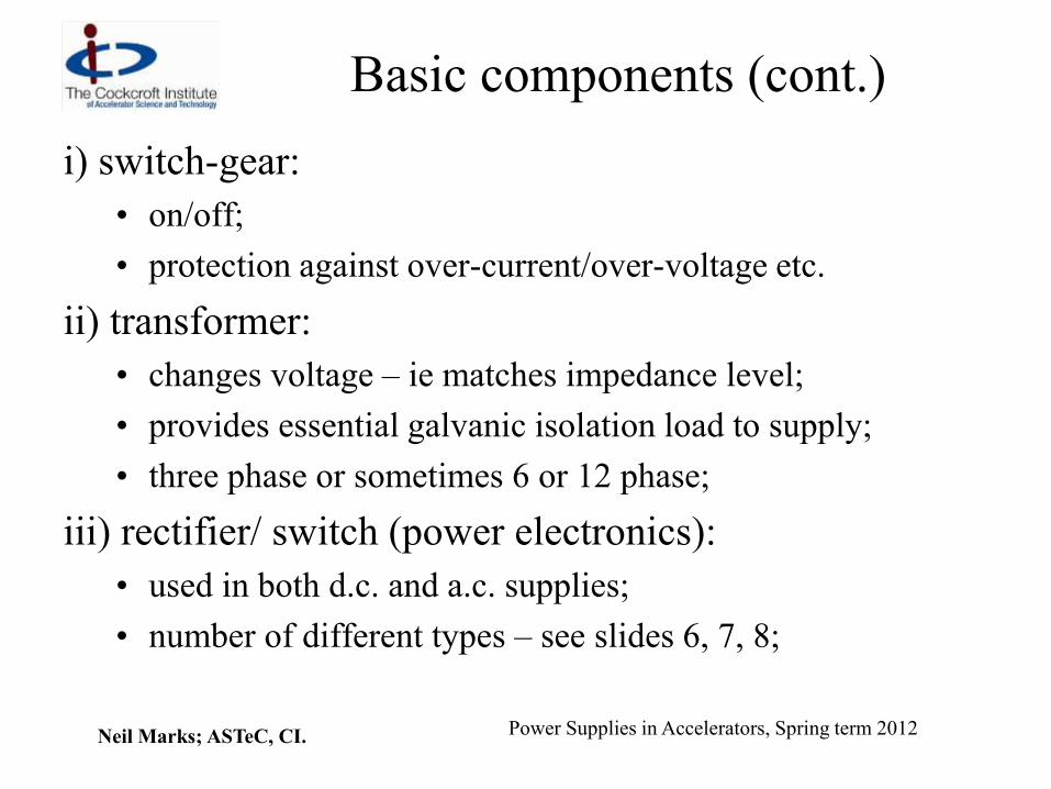
Basic components (cont.)
i) switch-gear:
• on/off;
• protection against over-current/over-voltage etc.
ii) transformer:
• changes voltage – ie matches impedance level;
• provides essential galvanic isolation load to supply;
• three phase or sometimes 6 or 12 phase;
iii) rectifier/ switch (power electronics):
• used in both d.c. and a.c. supplies;
• number of different types – see slides 6, 7, 8;

Neil Marks; ASTeC, CI. Power Supplies in Accelerators, Spring term 2012
Basic components (cont.)
iv) regulation:
• level setting;
• stabilisation with high gain servo system;
• strongly linked with ‘rectifier’ [item iii) above];
v) smoothing:
• using either a passive or active filter;
vi) monitoring:
• for feed-back signal for servo-system;
• for monitoring in control room;
• for fault detection.

Neil Marks; ASTeC, CI. Power Supplies in Accelerators, Spring term 2012
Switches - diode
• conducts in forward direction only;
• modern power devices can conduct in ~ 1 ms;
• has voltage drop of (< 1 V) when conducting;
• hence, dissipates power whilst conducting;
• ratings up to many 100s A (average), kVs peak reverse volts.
Neil Marks; ASTeC, CI. Power Supplies in Accelerators, Spring term 2012
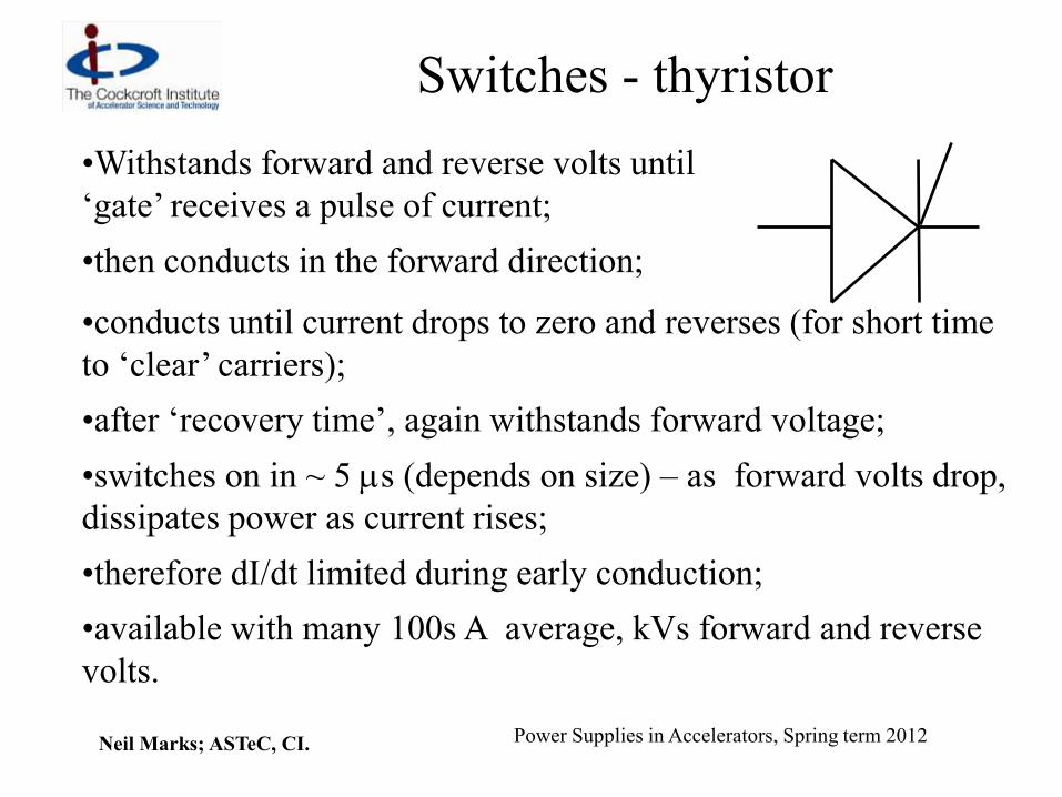
Switches - thyristor
•Withstands forward and reverse volts until
‘gate’ receives a pulse of current;
•then conducts in the forward direction;
•conducts until current drops to zero and reverses (for short time
to ‘clear’ carriers);
•after ‘recovery time’, again withstands forward voltage;
•switches on in ~ 5 ms (depends on size) – as forward volts drop,
dissipates power as current rises;
•therefore dI/dt limited during early conduction;
•available with many 100s A average, kVs forward and reverse
volts.
Neil Marks; ASTeC, CI. Power Supplies in Accelerators, Spring term 2012
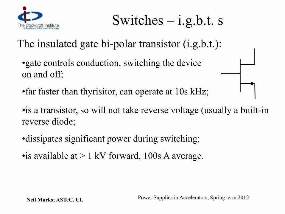
Switches – i.g.b.t. s
The insulated gate bi-polar transistor (i.g.b.t.):
•gate controls conduction, switching the device
on and off;
•far faster than thyrisitor, can operate at 10s kHz;
•is a transistor, so will not take reverse voltage (usually a built-in
reverse diode;
•dissipates significant power during switching;
•is available at > 1 kV forward, 100s A average.

Neil Marks; ASTeC, CI. Power Supplies in Accelerators, Spring term 2012
DC – single phase full-wave
rectifier
+
-
Classical ‘full-wave’ circuit:
•uncontrolled – no amplitude variation;
•large ripple – large capacitor smoothing necessary;
•only suitable for small loads.
-

Neil Marks; ASTeC, CI. Power Supplies in Accelerators, Spring term 2012
DC 3 phase diode rectifier
Vdc Vsw Vload
Iload
3 phase I/p
Fast switchRectifier
Cf Cf
Lf
LfLf
Lf
Three phase, six pulse system:
•no amplitude control;
•much lower ripple (~ 12% 6th harmonic – 300 Hz) but low-
pass filters still needed.
1 period 1 period 1 period 1 period 1 period
Neil Marks; ASTeC, CI. Power Supplies in Accelerators, Spring term 2012
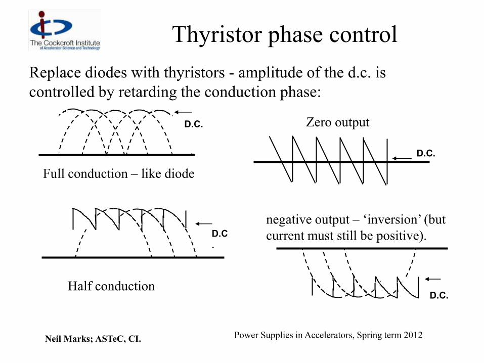
Thyristor phase control
Replace diodes with thyristors - amplitude of the d.c. is
controlled by retarding the conduction phase:
D.C
.
D.C.
D.C.
D.C.
Full conduction – like diode
Half conduction
Zero output
negative output – ‘inversion’ (but
current must still be positive).

Neil Marks; ASTeC, CI. Power Supplies in Accelerators, Spring term 2012
Full 12 pulse phase controlled
circuit.
Ii
Iii
Vi
Vii
Ipi
Iload
Vload
Lf
Lf
Lf
Lf
Cf
Cf
LOAD
3 phase i/p
11kV or 400V
•like all thyristor rectifiers, is ‘line commutated’;
•produces 600 Hz ripple (~ 6%)
•but smoothing filters still needed.

Neil Marks; ASTeC, CI. Power Supplies in Accelerators, Spring term 2012
The thyristor rectifier.
The ‘standard’ circuit until recently:
• gave good precision (better than 1:103);
• inversion protects circuit and load during faults;
• has bad power factor with large phase angles (V and I out of
phase in ac supply) ;
• injects harmonic contamination into load and 50 Hz a.c.
distribution system at large phase angles.

Neil Marks; ASTeC, CI. Power Supplies in Accelerators, Spring term 2012
Example of other (obsolete)
systems.
Passive FilterRectifierTransformer D.C. Output50Hz Mains
Network
Load
DCCT
3 Phase
400V or 11kV
50Hz Mains
Roller Regulator Series Regulation
This circuit uses:
•a variable transformer for changing level (very slow);
•diode rectification;
•a series regulator for precision (class A transistors !);
•good power factor and low harmonic injection into supply and
load.

Neil Marks; ASTeC, CI. Power Supplies in Accelerators, Spring term 2012
Modern ‘switch-mode’ system.
The i.g.b.t. allows a new, revolutionary system to be
used: the ‘switch-mode’ power supply:
Passive FilterRectifier D.C. Output50Hz Mains
Network
Load
DCCT
H.F.
TransformerInverter (kHz)
H.F.
Rectifier
D.C Bus
Neil Marks; ASTeC, CI. Power Supplies in Accelerators, Spring term 2012
Mode of operation
Stages of power conversion:
• incoming a.c. is rectified with diodes to give ‘raw’ d.c.;
• the d.c. is ‘chopped’ at high frequency (> 10 kHz) by an
inverter using i.g.b.t.s;
• a.c. is transformed to required level (transformer is much
smaller, cheaper at high frequency);
• transformed a.c. is rectified – diodes;
• filtered (filter is much smaller at 10 kHz);
• regulation is by feed-back to the inverter (much faster,
therefore greater stability);
• response and protection is very fast.

Neil Marks; ASTeC, CI. Power Supplies in Accelerators, Spring term 2012
Inverter
Point A: direct voltage source; current can be bidirectional (eg, inductive load,
capacitative source).
Point B: voltage square wave, bidirectional current.
The i.g.b.t. s
provide full
switching
flexibility –
switching on or
off according to
external control
protocols.
+
-+ -
+
-
+ -
+-
A B
The inverter is the heart of the switch-mode supply:

Neil Marks; ASTeC, CI. Power Supplies in Accelerators, Spring term 2012
Cycling converters (use a.c. ?)
The required magnetic field (magnet current) is unidirectional –
acceleration low to high energy: - so ‘normal’ a.c. is
inappropriate:
-1
0
1
0 7
•only ¼ cycle used;
•excess rms current;
•high a.c. losses;
•high gradient at
injection.
extraction
injection

Neil Marks; ASTeC, CI. Power Supplies in Accelerators, Spring term 2012
Nature of the Magnet Load
LM R
C
IM
VM Magnet current: IM;
Magnet voltage: VM
Series inductance: LM;
Series resistance: R;
Distributed capacitance to earth C.

Neil Marks; ASTeC, CI. Power Supplies in Accelerators, Spring term 2012
‘Reactive’ Power and Energy
voltage: VM = R IM + L (d IM/dt);
‘power’: VM IM = R (IM)2 + L IM(d IM/dt);
stored energy: EM = ½ LM (IM)2;
d EM /dt = L (IM) (d IM/dt);
so VM IM = R (IM )2
+ d EM /dt;
resistive power
loss;
reactive’ power – alternates
between +ve and –ve as field
rises and falls;
The challenge of the cyclic power converter is to provide and control
the positive and negative flow of energy - energy storage is required.

Neil Marks; ASTeC, CI. Power Supplies in Accelerators, Spring term 2012
Waveform criteria – eddy currents.
Generated by alternating magnetic field cutting a
conducting surface:
eddy current in vac. vessel & magnet; B/t;
eddy currents produce:
• negative dipole field - reduces main field magnitude;
• sextupole field – affects chromaticity/resonances;
eddy effects proportional (1/B)(dB/dt) – critical at injection.
B
B/t
Neil Marks; ASTeC, CI. Power Supplies in Accelerators, Spring term 2012
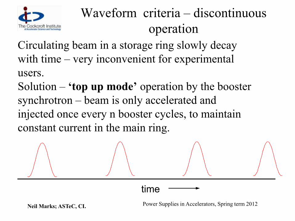
Waveform criteria – discontinuous
operation
Circulating beam in a storage ring slowly decay
with time – very inconvenient for experimental
users.
Solution – ‘top up mode’ operation by the booster
synchrotron – beam is only accelerated and
injected once every n booster cycles, to maintain
constant current in the main ring.
time -1.5
0
1.5
0 10
-1.5
0
1.5
0 10
-1.5
0
1.5
0 10
-1.5
0
1.5
0 10
Neil Marks; ASTeC, CI. Power Supplies in Accelerators, Spring term 2012
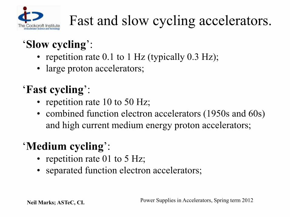
Fast and slow cycling accelerators.
‘Slow cycling’: • repetition rate 0.1 to 1 Hz (typically 0.3 Hz);
• large proton accelerators;
‘Fast cycling’: • repetition rate 10 to 50 Hz;
• combined function electron accelerators (1950s and 60s)
and high current medium energy proton accelerators;
‘Medium cycling’: • repetition rate 01 to 5 Hz;
• separated function electron accelerators;

Neil Marks; ASTeC, CI. Power Supplies in Accelerators, Spring term 2012
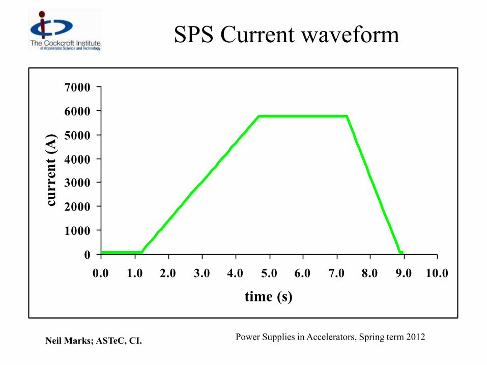
Example 1 – the CERN SPS
A slow cycling synchrotron.
Dipole power supply parameters (744 magnets):
• peak proton energy 450 GeV;
• cycle time (fixed target) 8.94 secs;
• peak current 5.75 kA;
• peak dI/dt 1.9 kA/s;
• magnet resistance 3.25 ;
• magnet inductance 6.6 H;
• magnet stored energy 109 MJ;
Neil Marks; ASTeC, CI. Power Supplies in Accelerators, Spring term 2012
SPS Current waveform
0
1000
2000
3000
4000
5000
6000
7000
0.0 1.0 2.0 3.0 4.0 5.0 6.0 7.0 8.0 9.0 10.0
time (s)
curr
ent
(A)
Neil Marks; ASTeC, CI. Power Supplies in Accelerators, Spring term 2012
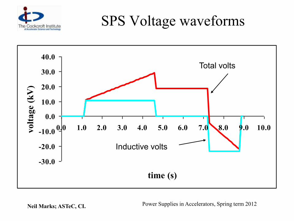
SPS Voltage waveforms
-30.0
-20.0
-10.0
0.0
10.0
20.0
30.0
40.0
0.0 1.0 2.0 3.0 4.0 5.0 6.0 7.0 8.0 9.0 10.0
time (s)
volt
age
(kV
)
Inductive volts
Total volts
Neil Marks; ASTeC, CI. Power Supplies in Accelerators, Spring term 2012
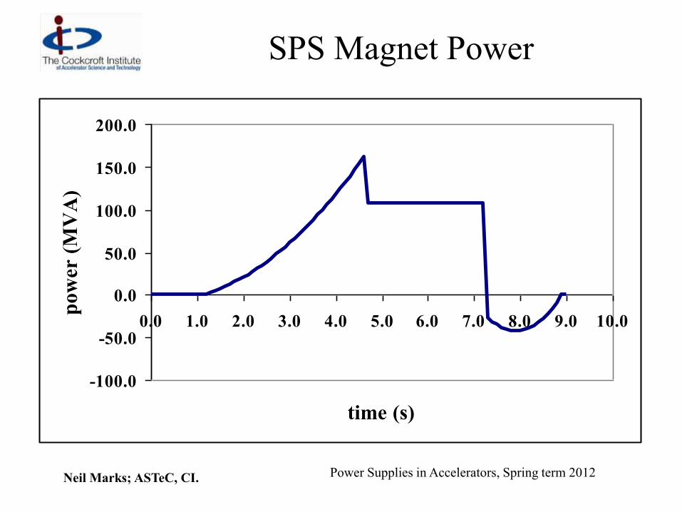
SPS Magnet Power
-100.0
-50.0
0.0
50.0
100.0
150.0
200.0
0.0 1.0 2.0 3.0 4.0 5.0 6.0 7.0 8.0 9.0 10.0
time (s)
po
wer
(M
VA
)

Neil Marks; ASTeC, CI. Power Supplies in Accelerators, Spring term 2012
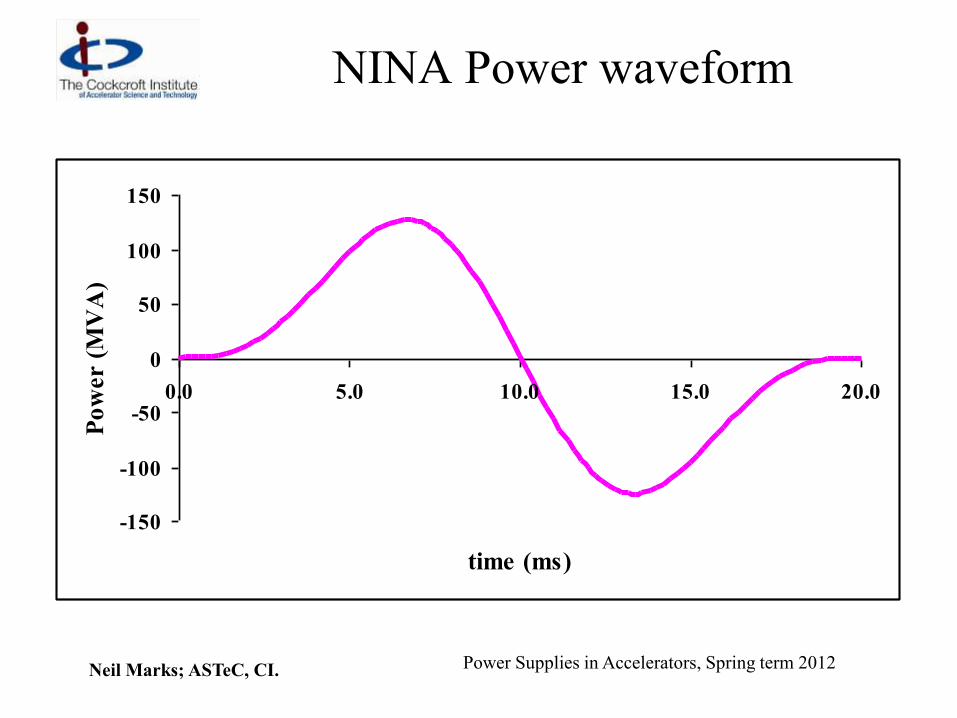
Example 2 – NINA (D.L.)
A fast cycling synchrotron
magnet power supply parameters;
• peak electron energy 5.0 GeV;
• cycle time 20 ms;
• cycle frequency 50 Hz
• peak current 1362 A;
• magnet resistance 900 m;
• magnet inductance 654 mH;
• magnet stored energy 606 kJ;

Neil Marks; ASTeC, CI. Power Supplies in Accelerators, Spring term 2012
NINA Current waveform
0
500
1000
1500
0.0 5.0 10.0 15.0 20.0
time (ms)
Cu
rren
t (A
)

Neil Marks; ASTeC, CI. Power Supplies in Accelerators, Spring term 2012
NINA Voltage waveform
-200
-150
-100
-50
0
50
100
150
200
0.0 5.0 10.0 15.0 20.0
time (ms)
Vo
lta
ge (
kV
)
Inductive voltage
Resistive voltage
Neil Marks; ASTeC, CI. Power Supplies in Accelerators, Spring term 2012
NINA Power waveform
-150
-100
-50
0
50
100
150
0.0 5.0 10.0 15.0 20.0
time (ms)
Po
wer (
MV
A)

Neil Marks; ASTeC, CI. Power Supplies in Accelerators, Spring term 2012
Cycling converter requirements
A power converter system needs to provide:
• a unidirectional alternating waveform;
• accurate control of waveform amplitude;
• accurate control of waveform timing;
• storage of magnetic energy during low field;
• if possible, waveform control;
• if needed (and possible) discontinuous operation
for ‘top up mode’.

Neil Marks; ASTeC, CI. Power Supplies in Accelerators, Spring term 2012
‘Slow Cycling’ Mechanical
Storage Examples: all large proton
accelerators built in 1950/60s.
waveform
control !
d.c. motor
to make up
losses high inertia
fly-wheel
to store
energy
a.c alternator/
synchronous
motor rectifier/
inverter magnet

Neil Marks; ASTeC, CI. Power Supplies in Accelerators, Spring term 2012
‘Nimrod’
The alternator,
fly-wheel
and d.c. motor
of the 7 GeV
weak-focusing
synchrotron,
NIMROD

Neil Marks; ASTeC, CI. Power Supplies in Accelerators, Spring term 2012
‘Slow cycling’ direct connection to supply
network
National supply networks have large stored
(inductive) energy; given the correct interface, this
can be utilised to provide and receive back the
reactive power of a large accelerator.
Compliance with supply authority regulations must
minimise:
• voltage ripple at feeder;
• phase disturbances;
• frequency fluctuations over the network.
A ‘rigid’ high voltage line in is necessary.

Neil Marks; ASTeC, CI. Power Supplies in Accelerators, Spring term 2012
Example - Dipole supply for the
SPS 14 converter modules (each 2
sets of 12 pulse phase
controlled thyristor rectifiers)
supply the ring dipoles in
series; waveform control!
Each module is connected to its
own 18 kV feeder, which are
directly fed from the 400 kV
French network.
Saturable reactor/capacitor
parallel circuits limit voltage
fluctuations.

Neil Marks; ASTeC, CI. Power Supplies in Accelerators, Spring term 2012
Medium & fast cycling inductive
storage.
Fast and medium cycling accelerators (mainly
electron synchrotrons) developed in 1960/70s used
inductive energy storage:
inductive storage was roughly half the cost per kJ of
capacitative storage.
The ‘standard circuit’ was developed at Princeton-Pen
accelerator – the ‘White Circuit’.

Neil Marks; ASTeC, CI. Power Supplies in Accelerators, Spring term 2012
White Circuit – single cell.
DC
Supply
accelerator
magnets
LM
C1 C2
Energy
storage
choke LCh
a.c.
supply
Examples: Boosters for ESRF, SRS; (medium to fast cycling
‘small’ synchrotrons).

Neil Marks; ASTeC, CI. Power Supplies in Accelerators, Spring term 2012
White circuit (cont.)
Single cell circuit:
• magnets are all in series (LM);
• circuit oscillation frequency ;
• C1 resonates magnet in parallel: C1 = 2/LM;
• C2 resonates energy storage choke:C2 = 2/LCh;
• energy storage choke has a primary winding
closely coupled to the main winding;
• only small ac present in d.c. source;
• no d.c. present in a.c source;
• NO WAVEFORM CONTROL.

Neil Marks; ASTeC, CI. Power Supplies in Accelerators, Spring term 2012
White Circuit magnet waveform
Magnet current is biased sin wave – amplitude of IAC
and IDC independently controlled.
-1.5
0
1.5
0 10IDC
IAC
0
Usually fully
biased,
so IDC ~ IAC

Neil Marks; ASTeC, CI. Power Supplies in Accelerators, Spring term 2012
Multi-cell White Circuit (NINA, DESY &
others)
dc
ac
L
L
L
L
C
C
M
M
Ch
Ch
For high voltage circuits, the
magnets are segmented into
a number of separate groups.
earth point
Neil Marks; ASTeC, CI. Power Supplies in Accelerators, Spring term 2012
Multi-cell White circuit (cont.)
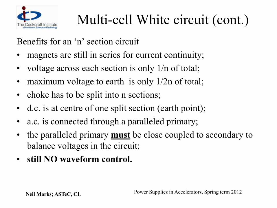
Benefits for an ‘n’ section circuit
• magnets are still in series for current continuity;
• voltage across each section is only 1/n of total;
• maximum voltage to earth is only 1/2n of total;
• choke has to be split into n sections;
• d.c. is at centre of one split section (earth point);
• a.c. is connected through a paralleled primary;
• the paralleled primary must be close coupled to secondary to
balance voltages in the circuit;
• still NO waveform control.
Neil Marks; ASTeC, CI. Power Supplies in Accelerators, Spring term 2012
Modern Capacitative Storage
Technical and economic developments in electrolytic capacitors
manufacture now result in capacitiative storage being lower cost
than inductive energy storage (providing voltage reversal is not
needed).
Also semi-conductor technology now allows the use of fully
controlled devices (i.g.b.t. s) giving waveform control at
medium current and voltages.
Medium sized synchrotrons with cycling times of 1 to 5 Hz can
now take advantage of these developments for cheaper and
dynamically controllable power magnet converters –
WAVEFORM CONTROL!

Neil Marks; ASTeC, CI. Power Supplies in Accelerators, Spring term 2012
Example: Swiss Light Source Booster
dipole circuit.
acknowledgment :Irminger, Horvat, Jenni, Boksberger, SLS

Neil Marks; ASTeC, CI. Power Supplies in Accelerators, Spring term 2012
SLS Booster parameters
Hz 3 Cycling frequency
kJ 28 Stored energy
A 950 Max current
mH 80 Inductance
m 600 Resistance
48 BD
45 BF
Combined function dipoles
acknowledgment :Irminger, Horvat, Jenni, Boksberger, SLS

Neil Marks; ASTeC, CI. Power Supplies in Accelerators, Spring term 2012
SLS Booster Waveforms
-500
-250
0
250
500
750
1000
1
50
10
0
15
0
20
0
25
0
30
0
35
0CU
RR
EN
T [
A]
/ V
OL
TA
GE
[V
]
-250
0
250
500
750
1000
1
50
10
0
15
0
20
0
25
0
30
0
35
0
PO
WE
R [
kW
]

Neil Marks; ASTeC, CI. Power Supplies in Accelerators, Spring term 2012
SLS Booster Waveforms
The storage capacitor only discharges a fraction of its stored
energy during each acceleration cycle:
0 0.1 0.2 0.3 0.4 0.5 0.6 0.7 0.8 0.9 1 0
100
200
300
400
500
600
TIME [s]
2Q input voltage
[V]
dc/dc input current
[A]
Neil Marks; ASTeC, CI. Power Supplies in Accelerators, Spring term 2012
Assessment of switch-mode circuit
Comparison with the White Circuit:
• the s.m.circuit does not need a costly energy storage
choke with increased power losses;
• within limits of rated current and voltage, the s.m.c.
provides flexibility of output waveform;
• after switch on, the s.m.c. requires less than one
second to stabilise (valuable in ‘top up mode’).
However:
• the current and voltages possible in switched circuits
are restricted by component ratings.
Neil Marks; ASTeC, CI. Power Supplies in Accelerators, Spring term 2012
Diamond Booster parameters for SLS
type circuit
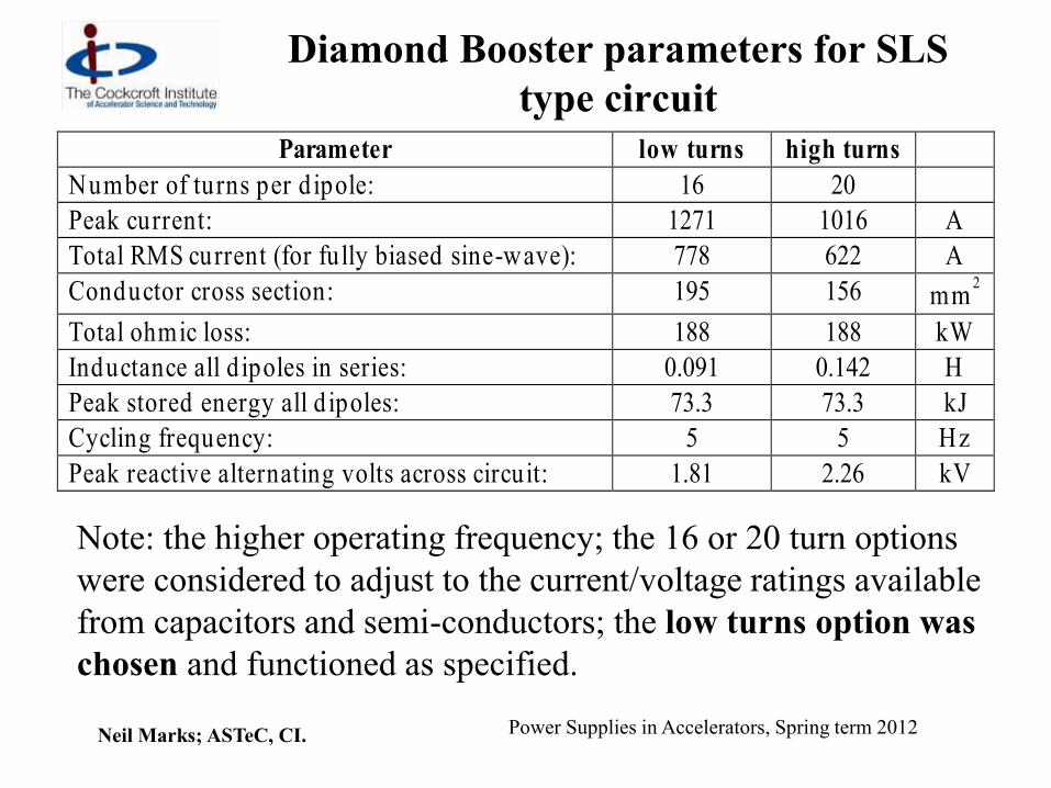
Parameter low turns high turns
Number of turns per d ipole: 16 20
Peak current: 1271 1016 A
Total RMS current (for fully biased sine-wave): 778 622 A
Conductor cross section: 195 156 mm2
Total ohmic loss: 188 188 kW
Inductance all d ipoles in series: 0.091 0.142 H
Peak stored energy all d ipoles: 73.3 73.3 kJ
Cycling frequency: 5 5 Hz
Peak reactive alternating volts across circuit: 1.81 2.26 kV
Note: the higher operating frequency; the 16 or 20 turn options
were considered to adjust to the current/voltage ratings available
from capacitors and semi-conductors; the low turns option was
chosen and functioned as specified.

Neil Marks; ASTeC, CI. Power Supplies in Accelerators, Spring term 2012
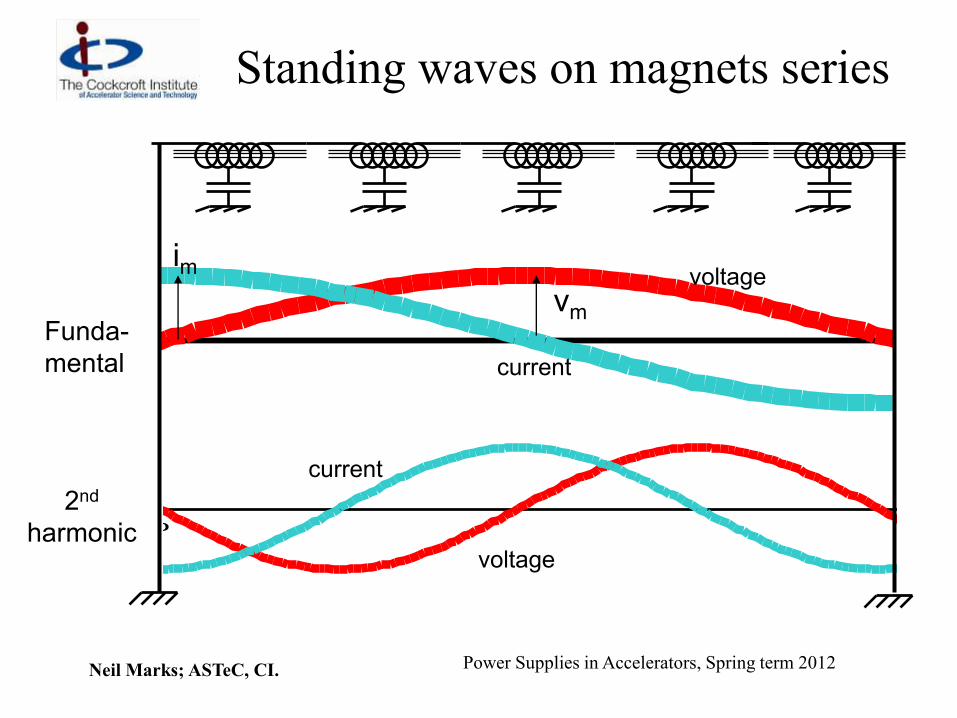
Delay-line mode of resonance
Most often seen in cycling circuits (high field disturbances
produce disturbance at next injection); but can be present in any
system.
Stray capacitance to earth makes the inductive magnet string a
delay line. Travelling and standing waves (current and voltage)
on the series magnet string: different current in dipoles at
different positions!
Neil Marks; ASTeC, CI. Power Supplies in Accelerators, Spring term 2012
Standing waves on magnets series
-1.5
0
1.5
0 10
-1.5
0
1.5
0 10
Funda-
mental
2nd
harmonic
voltage
current
current
voltage
vm
im

Neil Marks; ASTeC, CI. Power Supplies in Accelerators, Spring term 2012
Delay-line mode equations
LM is total magnet inductance;
C is total stray capacitance;
Then:
surge impedance:
Z = vm/im = (LM/C);
transmission time:
= (LMC);
fundamental frequency:
1 = 1/{ 2 (LMC) }
LM R
C

Neil Marks; ASTeC, CI. Power Supplies in Accelerators, Spring term 2012
Excitation of d.l.m.r.
The mode will only be excited if rapid voltage-to-earth
excursions are induced locally at high energy in the
magnet chain (‘beam-bumps’); the next injection is
then compromised:
• keep stray capacitance as low as possible;
• avoid local disturbances in magnet ring;
• solutions (damping loops) are possible.
V
propagation

Neil Marks; ASTeC, CI. Power Supplies in Accelerators, Spring term 2012
Conclusion
Magnet power supplies in accelerators:
• need to provide safe, high precision, highly reliable
operation;
• will comprise advanced, complex electrical
engineering systems;
• have limitations and constraints that need to be
clearly understood during the conceptual design and
construction of accelerators.