Power Ssytem Analysis Solution VII Sem 2013
19
UNIT – I Q.1(a) What is per unit system. How the base qu antity selected. What are the Advantages of Per Unit System Ans. The per unit value o f any quantity is the ratio of the actual value in any units to the chosen base quantify of the same dimensions expressed as a decimal. Per unit quantity = In power systems the basic quantities of importance are voltage, current, impedance and power. For all per unit calculations a base KVA or MVA and a base KV are to be chosen. Once the base values or reference values are chosen. the other quantities can be ohtained as follows: Selecting the total or 3-phase KVA as base KVA, for a 3-phase s ystem Base current in amperes= Base Impedance In ohms = Hence, Base Impedance in ohm= Advantages of Per Unit System
-
Upload
hodeegits9526 -
Category
Documents
-
view
215 -
download
0
Transcript of Power Ssytem Analysis Solution VII Sem 2013
8/12/2019 Power Ssytem Analysis Solution VII Sem 2013
http://slidepdf.com/reader/full/power-ssytem-analysis-solution-vii-sem-2013 1/19
UNIT – I
Q.1(a) What is per unit system. How the base quantity selected. What are the Advantages of Per
Unit System
Ans. The per unit value of any quantity is the ratio of the actual value in any units to the chosen
base quantify of the same dimensions expressed as a decimal.
Per unit quantity =
In power systems the basic quantities of importance are voltage, current, impedance and power.
For all per unit calculations a base KVA or MVA and a base KV are to be chosen. Once the base
values or reference values are chosen. the other quantities can be ohtained as follows:
Selecting the total or 3-phase KVA as base KVA, for a 3-phase system
Base current in amperes=
Base Impedance In ohms =
Hence, Base Impedance in ohm=
Advantages of Per Unit System
8/12/2019 Power Ssytem Analysis Solution VII Sem 2013
http://slidepdf.com/reader/full/power-ssytem-analysis-solution-vii-sem-2013 2/19
1. While performing calculations, referring quantities from one side of the transformer to the
other side serious errors may be committed. This can be avoided by using per unit system.
2. Voltages, currents and impedances expressed in per unit do not change when they are referred
from one side of transformer to the other side. This is a great advantage'.
3. Per unit impedances of electrical equipment of similar type usually lie within a narrow range,
when the equipment ratings are used as base values.
4. Transformer connections do not affect the per unit values.
5. Manufacturers usually specify the impedances of machines and transformers in per unit or
percent of name plate ratings.
Q.1 (b) Solution
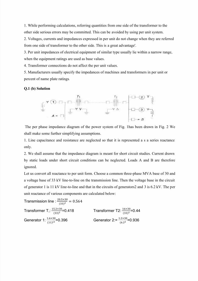
The per phase impedance diagram of the power system of Fig. 1has been drawn in Fig. 2 We
shall make some further simplifying assumptions.
1. Line capacitance and resistance are neglected so that it is represented a s a series reactance
only.2. We shall assume that the impedance diagram is meant for short circuit studies. Current drawn
by static loads under short circuit conditions can be neglected. Loads A and B are therefore
ignored.
Let us convert all reactance to per unit form. Choose a common three-phase MVA base of 30 and
a voltage base of 33 kV line-to-line on the transmission line. Then the voltage base in the circuit
of generator 1 is 11 kV line-to-line and that in the circuits of generators2 and 3 is 6.2 kV. The per
unit reactance of various components are calculated below:
Transmission line :
Transformer T,:
=0.418 Transformer T2:
=0.44
Generator 1:
=0.396 Generator 2:=
=0.936

8/12/2019 Power Ssytem Analysis Solution VII Sem 2013
http://slidepdf.com/reader/full/power-ssytem-analysis-solution-vii-sem-2013 3/19
Generator 3:=
=0.437
The reactanced iagramo f the system is shown in Fig
OR
Q.1(a) Classification of Buses
(a) Load hus : A bus where there is only load connected and no generation exists is called a load
bus. At this bus real and reactive load demand Pd and Qd are drawn from the supply. The
demand is generally estimated or predicted as in load forecast or metered and measured from
instruments. Quite often, the reactive power is
calculated from real power demand with an assumed power factor.
A load bus is called a p, Q bus. Since the load demands Pd and Qd are known values at this bus.
The other two unknown quantities at a load bus are voltage magnitude and its phase angle at the
bus. In a power balance equation P d and Qd are treated as negative quantities since generated
powers P g and Q g are assumed positive.
(b) VoltaKe controlled bus or generator bus:
A voltage controlled bus is any bus in the system where the voltage magnitude can be controlled.
The real power developed by a synchronous generator can be varied b: changing the prime
mover input. This in turn changes the machine rotor axis position with respect to a
synchronously rotating or reference axis or a reference bus. In other words, the phase angle of
the rotor 0 is directly related to the real power generated by the machine. The voltage magnitude
on the other hand, i~ mainly, influenced by the excitation current in the field winding. Thus at a
generator bus the real power generation P" and the voltage magnitude IV 01 can be specified. It
is also possible to produce vars by using capacitor or reactor banks too. They compensate the
lagging or leading val's consumed and then contribute to voltage control. At a generator bus or
8/12/2019 Power Ssytem Analysis Solution VII Sem 2013
http://slidepdf.com/reader/full/power-ssytem-analysis-solution-vii-sem-2013 4/19
voltage controlled bus, also called a PV-bus the reactive power Qg and 8fl are the values that are
not known and are to be computed.
(c) Slack Bus
In a network as power tlow~ from the generators to loads through transmission lines power loss
occurs due to the losses in the line conductors. These losses when included, we get the power
balance relations
Pg-Pd- Pi=0 Qg-Qd-QI =0
where Pg and Qg are the total real and reactive generations, Pd and Qd are the total real and
reactive power demands and P land OI. are the power losses in the transmission network. The
values of Pg' Qg' Pd and Qd are either known or estimated.
Since the flow of cements in the various lines in the transmission lines are not known in advance,
PI. and QI. remains unknown before the analysis of the network.But. these losses have to be
supplied by the generators in the system.
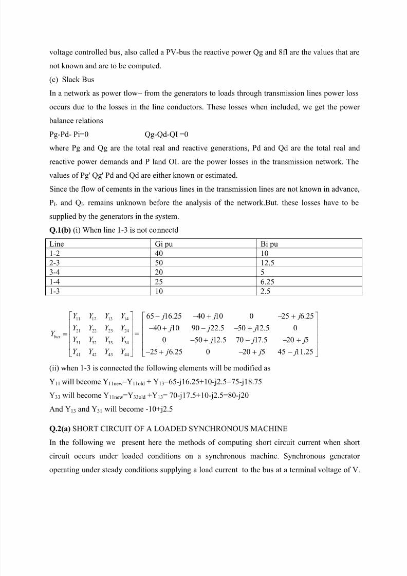
Q.1(b) (i) When line 1-3 is not connectd
Line Gi pu Bi pu
1-2 40 10
2-3 50 12.5
3-4 20 5
1-4 25 6.25
1-3 10 2.5
11 12 13 14
21 22 23 24
31 32 33 34
41 42 43 44
bus
Y Y Y Y
Y Y Y Y Y
Y Y Y Y
Y Y Y Y
=
65 16.25 40 10 0 25 6.25
40 10 90 22.5 50 12.5 0
0 50 12.5 70 17.5 20 5
25 6.25 0 20 5 45 11.25
j j j
j j j
j j j
j j j
(ii) when 1-3 is connected the following elements will be modified as
Y11 will become Y11new=Y11old + Y13=65-j16.25+10-j2.5=75-j18.75
Y33 will become Y11new=Y33old +Y13= 70-j17.5+10-j2.5=80-j20
And Y13 and Y31 will become -10+j2.5
Q.2(a) SHORT CIRCUIT OF A LOADED SYNCHRONOUS MACHINE
In the following we present here the methods of computing short circuit current when short
circuit occurs under loaded conditions on a synchronous machine. Synchronous generator
operating under steady conditions supplying a load current to the bus at a terminal voltage of V.
8/12/2019 Power Ssytem Analysis Solution VII Sem 2013
http://slidepdf.com/reader/full/power-ssytem-analysis-solution-vii-sem-2013 5/19
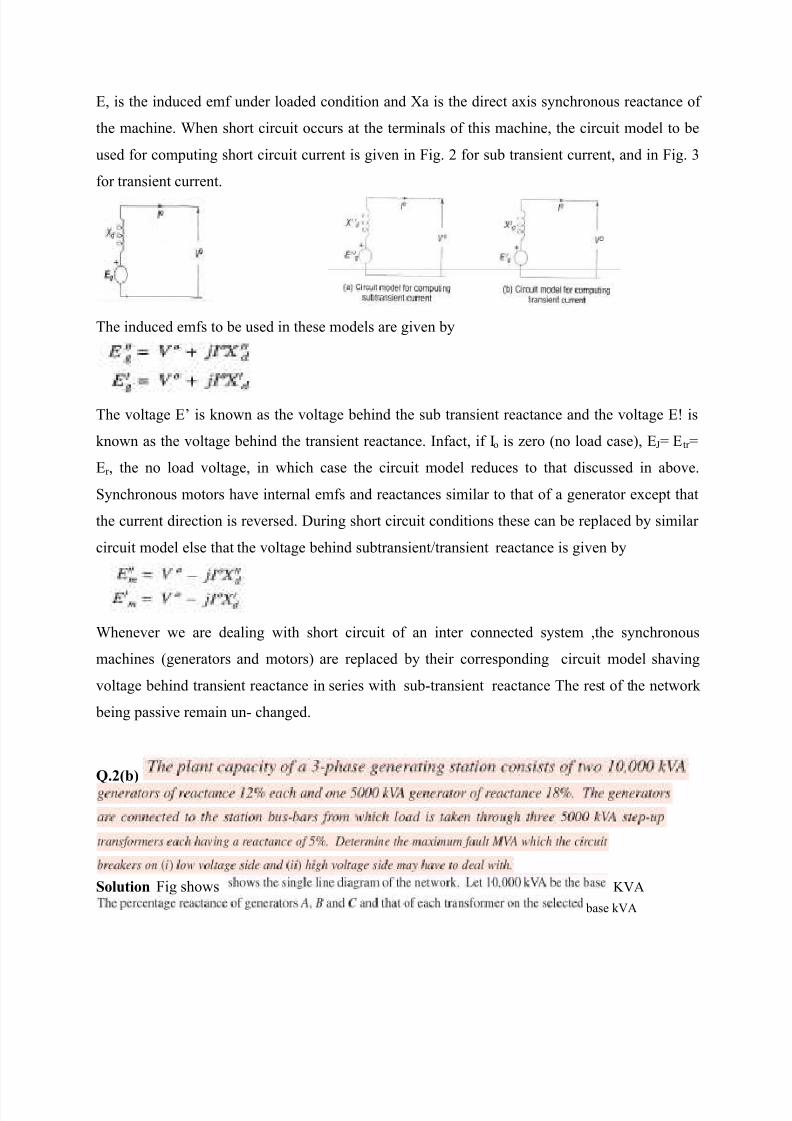
E, is the induced emf under loaded condition and Xa is the direct axis synchronous reactance of
the machine. When short circuit occurs at the terminals of this machine, the circuit model to be
used for computing short circuit current is given in Fig. 2 for sub transient current, and in Fig. 3
for transient current.
The induced emfs to be used in these models are given by
The voltage E’ is known as the voltage behind the sub transient reactance and the voltage E! is
known as the voltage behind the transient reactance. Infact, if Io is zero (no load case), EJ= Etr =
Er , the no load voltage, in which case the circuit model reduces to that discussed in above.
Synchronous motors have internal emfs and reactances similar to that of a generator except that
the current direction is reversed. During short circuit conditions these can be replaced by similar
circuit model else that the voltage behind subtransient/transient reactance is given by
Whenever we are dealing with short circuit of an inter connected system ,the synchronous
machines (generators and motors) are replaced by their corresponding circuit model shaving
voltage behind transient reactance in series with sub-transient reactance The rest of the network
being passive remain un- changed.
Q.2(b)
Solution Fig shows KVA
base kVA

8/12/2019 Power Ssytem Analysis Solution VII Sem 2013
http://slidepdf.com/reader/full/power-ssytem-analysis-solution-vii-sem-2013 6/19
%XA=
e
=5.14%
2

8/12/2019 Power Ssytem Analysis Solution VII Sem 2013
http://slidepdf.com/reader/full/power-ssytem-analysis-solution-vii-sem-2013 7/19

8/12/2019 Power Ssytem Analysis Solution VII Sem 2013
http://slidepdf.com/reader/full/power-ssytem-analysis-solution-vii-sem-2013 8/19
or or
or X=
%X=
Ohm
Q.3(a) An unbalanced system ofn phasors can be resolved into n systems of balanced phasors.
These subsystems of balanced phasors are called symmetrical components. With reference to 3- phase systems the following balanced set of three components are identified and defined.
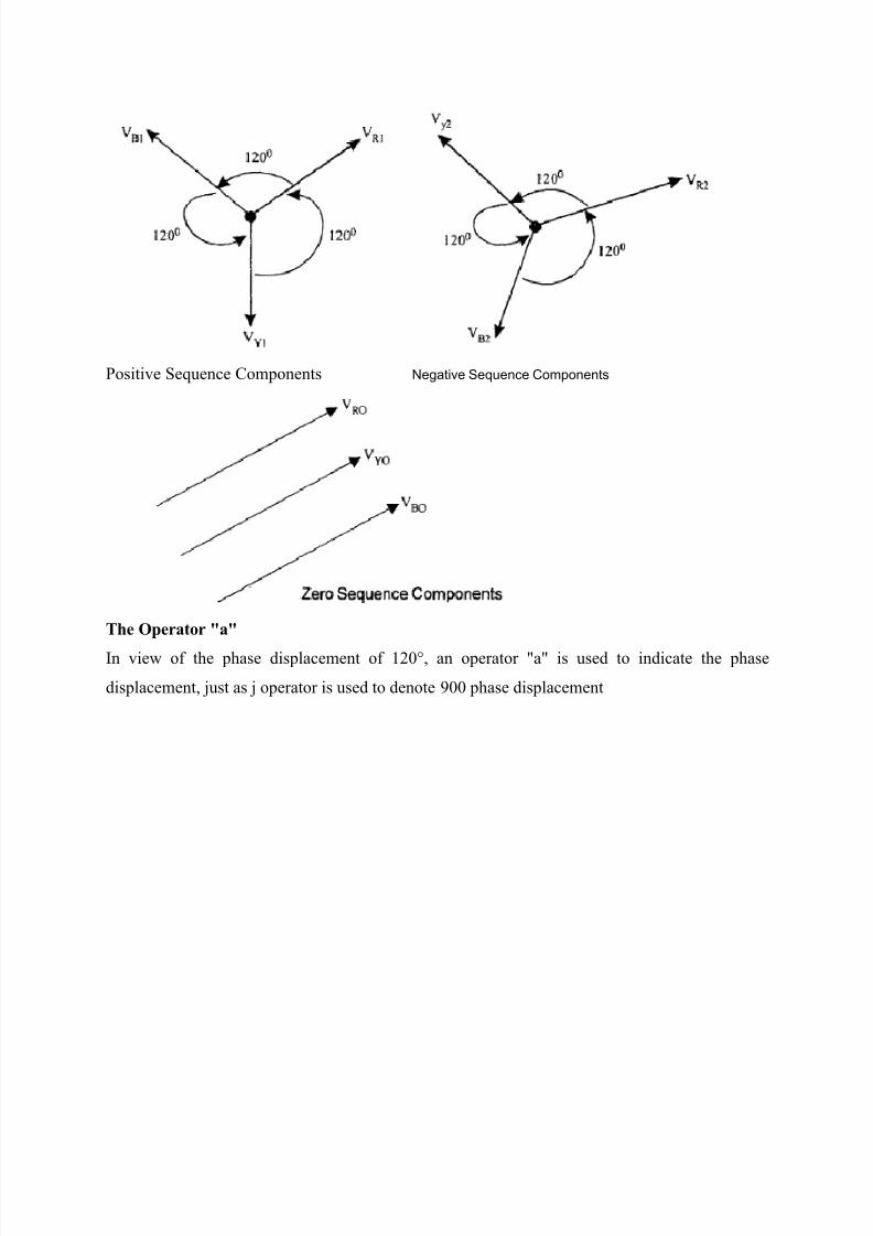
(a) Set of three phasors equal in magnitude, displaced from each other by 1200 in phase and
having the same phase sequence as the original phasors constitute positive sequence components.
They are denoted by the suffix 1.
(b) Set of three phasors equal in magnitude, displaced from each other by 1200 in phase, and
having a phase sequence opposite to that of the original phasors constitute the negative sequence
components. They are denoted by the suffix 2.
(c) Set of three phasors equal in magnitude and alI in phase (with no mutual phase displacement)
constitute zero sequence components. They are denoted by the suffix 0.
Denoting the phases as R, Y and B V R' V Y and VB are the unbalanced phase voltages. These
voltages are expressed in terms of the sequence components
V R1' VY1' VB1
V R2' VY2' VB2
and VRO' VYO' VBO as folIows :-
VR =VRI+VR2+VRO ..... (7.1)
Vy=VYI + Vy2 +VO
VB = VB I + VB2 + V0
8/12/2019 Power Ssytem Analysis Solution VII Sem 2013
http://slidepdf.com/reader/full/power-ssytem-analysis-solution-vii-sem-2013 9/19
Positive Sequence Components Negative Sequence Components
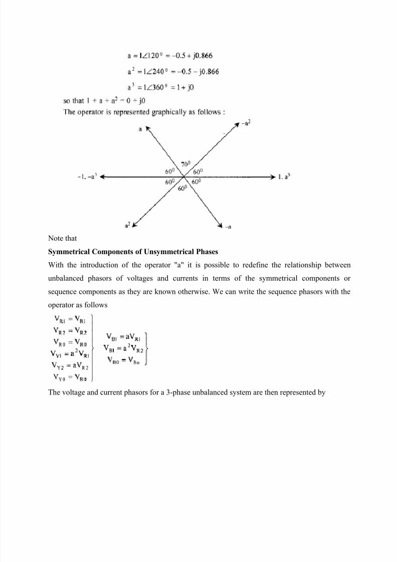
The Operator "a"
In view of the phase displacement of 120°, an operator "a" is used to indicate the phase
displacement, just as j operator is used to denote 900 phase displacement
8/12/2019 Power Ssytem Analysis Solution VII Sem 2013
http://slidepdf.com/reader/full/power-ssytem-analysis-solution-vii-sem-2013 10/19
Note that
Symmetrical Components of Unsymmetrical Phases
With the introduction of the operator "a" it is possible to redefine the relationship between
unbalanced phasors of voltages and currents in terms of the symmetrical components or
sequence components as they are known otherwise. We can write the sequence phasors with theoperator as follows
The voltage and current phasors for a 3-phase unbalanced system are then represented by

8/12/2019 Power Ssytem Analysis Solution VII Sem 2013
http://slidepdf.com/reader/full/power-ssytem-analysis-solution-vii-sem-2013 11/19
The above equations can be put in matrix form considering zero sequence relation as the first for
convenience.
Eqs. above relate the sequence components to the phase components through the transformation
matrix
Q.3 (b) This is case of balanced load supplied by unbalanced supply 0100 0 R E ,
0200 270Y E and 0100 120 B E Resistance in each phase of star connection is 10,000 ohm
OR
Q.3 Let base MVA =100, Base KV = 11KVand
For Generator Z1=Z2=j0.2 and Z0=j0.05
Line Z1=Z2=j0.05 and Z0= j0.15
Motor has Z1= Z2=
2100 11
0.250 11
=0.4 and Z0=
2100 11
0.0550 11
=j0.1
Pre-fault condition
Load = 40 MW at 0.8 pf (leading)=40
0.8=50MVA=
50
100 pu=0.5pu
Motor terminal voltage =10.95
11 pu=0.995pu
8/12/2019 Power Ssytem Analysis Solution VII Sem 2013
http://slidepdf.com/reader/full/power-ssytem-analysis-solution-vii-sem-2013 12/19
Motor current Im=0.5
0.995 pu=0.5 36.86 leading=0.5(0.8-j0.6)=0.4-j0.3
Pre-fault voltage at generator terminal=0.995+Im(j0.2+j0.05)=0.9799+j0.0201
At the fault location Z1=Z2=( 0.2)( 0.25)
(0.2 0.25)
j j
j =j0.11 and Z0=
( 0.05)( 0.15)
(0.05 0.15)
j j
j
The sequence components of fault current are
Ia1=Ia2=Ia0=0.9799 0.0201
0.06 3.075(0.1385 0.1385 0.0417)
j j
j
pu
Component of positive sequence of fault current through generator=
(0.06-j3.075)( 0.45)
0.04 2.13( 0.65)
j j
j pu
Component of positive sequence of fault current through motor=
(j0.25)(0.06-j3.075) 0.05 2.56
(j0.65) j
Negative sequence current components are same
Similarly zero se current are 0.01-j0.515pu from generator and 0.01-j0.515pu from motor
The current in phase a of the motor =(-0.382-j1.246)+(0.02-j0.945)+(0.01-0.515)=14427.5
262.6
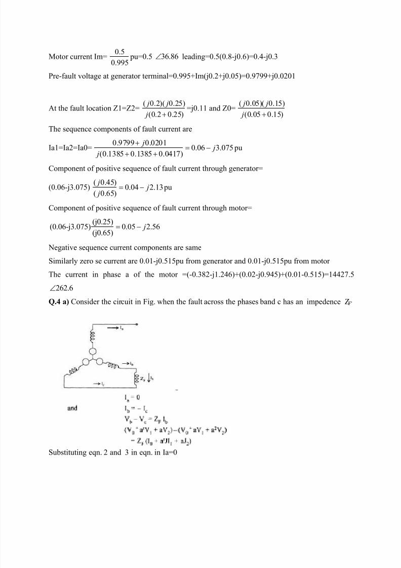
Q.4 a) Consider the circuit in Fig. when the fault across the phases band c has an impedence ZF'
Substituting eqn. 2 and 3 in eqn. in Ia=0
8/12/2019 Power Ssytem Analysis Solution VII Sem 2013
http://slidepdf.com/reader/full/power-ssytem-analysis-solution-vii-sem-2013 13/19
The sequence nehosh connection in this case will be as shown in Fig. 2
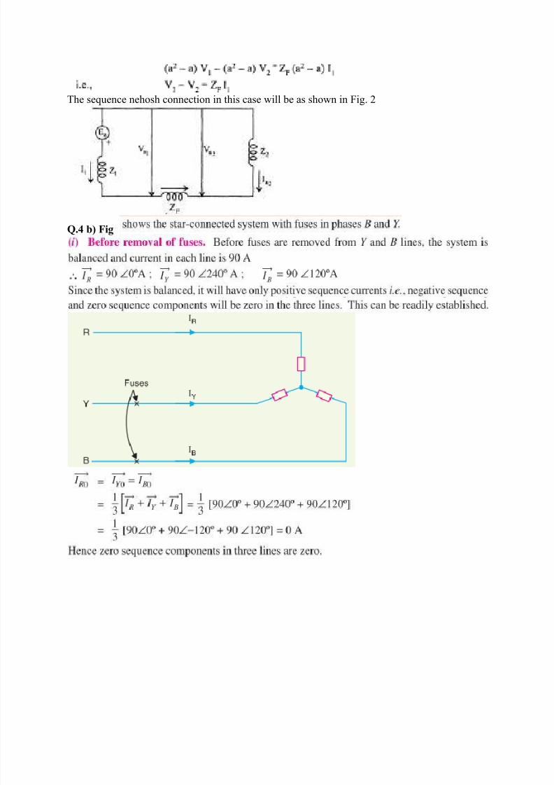
Q.4 b) Fig

8/12/2019 Power Ssytem Analysis Solution VII Sem 2013
http://slidepdf.com/reader/full/power-ssytem-analysis-solution-vii-sem-2013 14/19
IY=IB=0
They are
8/12/2019 Power Ssytem Analysis Solution VII Sem 2013
http://slidepdf.com/reader/full/power-ssytem-analysis-solution-vii-sem-2013 15/19
OR
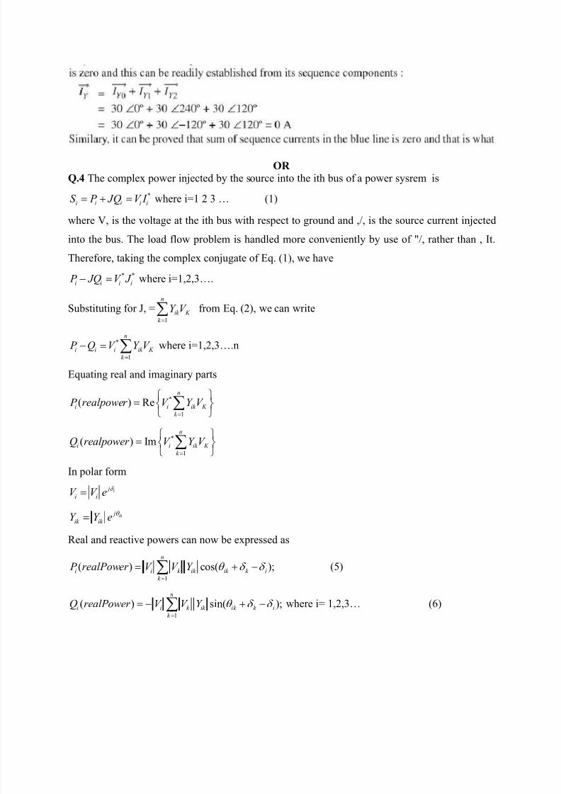
Q.4 The complex power injected by the source into the ith bus of a power sysrem is
*
i i i i iS P JQ V I where i=1 2 3 … (1)
where V, is the voltage at the ith bus with respect to ground and ,/, is the source current injected
into the bus. The load flow problem is handled more conveniently by use of "/, rather than , It.
Therefore, taking the complex conjugate of Eq. (1), we have
* *i i i i P JQ V J where i=1,2,3….
Substituting for J, =1
n
ik K
k
Y V
from Eq. (2), we can write
*
1
n
i i i ik K
k
P Q V Y V
where i=1,2,3….n
Equating real and imaginary parts
*
1
( ) Ren
i i ik K
k
P realpower V Y V
*
1
( ) Imn
i i ik K
k
Q realpower V Y V
In polar form
i j
i iV V e
ik j
ik ik Y Y e
Real and reactive powers can now be expressed as
1
( ) cos( );n
i i k ik ik k i
k
P realPower V V Y
(5)
1
( ) sin( );n
i i k ik ik k i
k
Q realPower V V Y
where i= 1,2,3… (6)

8/12/2019 Power Ssytem Analysis Solution VII Sem 2013
http://slidepdf.com/reader/full/power-ssytem-analysis-solution-vii-sem-2013 16/19
Equations (5) and (6) represent 2n power flow equations at n buses of a power system (n real
power flow equations and n reactive power flow equations).E ach bus is characterized by four
variables; P;, Qi, Vi and δi resulting in a total of 4n variables. Equations (6.27) and (6.28) can be
solved for 2n variables if the remaining 2n variables are specified. Practical considerations allow
a power system analyst to fix a priori two variables at each bus. The solution for the remaining
2n bus variables is rendered difficult by the fact that Eqs. (5) and (6) are non-linear algebraic
equations (bus voltages are involved in product form and sine and cosine terms are present) and
therefore explicit solution is not possible Solution can only be obtained by iterative numerical
techniques.
Q.5b) The Rectangular Coordinates Method
The power entering the bus i is given by
*i i i i iS P JQ V I
Expanding the right side of the above equation and separating out the real and imaginary parts
These are the two power relations at each bus and the lineanzed equations of the form are
written as

8/12/2019 Power Ssytem Analysis Solution VII Sem 2013
http://slidepdf.com/reader/full/power-ssytem-analysis-solution-vii-sem-2013 17/19
Matrix equation (5.53) can be solved for the unknowns ~v: and ~< (i = I, 2, ... , n -1), leaving the
slack bus at the nth bus where the voltage is specified. Equation (2.33) may be written compactly
as
where H, N, M and L are the sub-matrices of the Jacobian. The elements of the Jacobian are
obtained by differentiating Eqns.. The off-diagonal and diagonal elements of
H matrix are given by
The off-diagonal and diagonal elements ofN are:
8/12/2019 Power Ssytem Analysis Solution VII Sem 2013
http://slidepdf.com/reader/full/power-ssytem-analysis-solution-vii-sem-2013 18/19
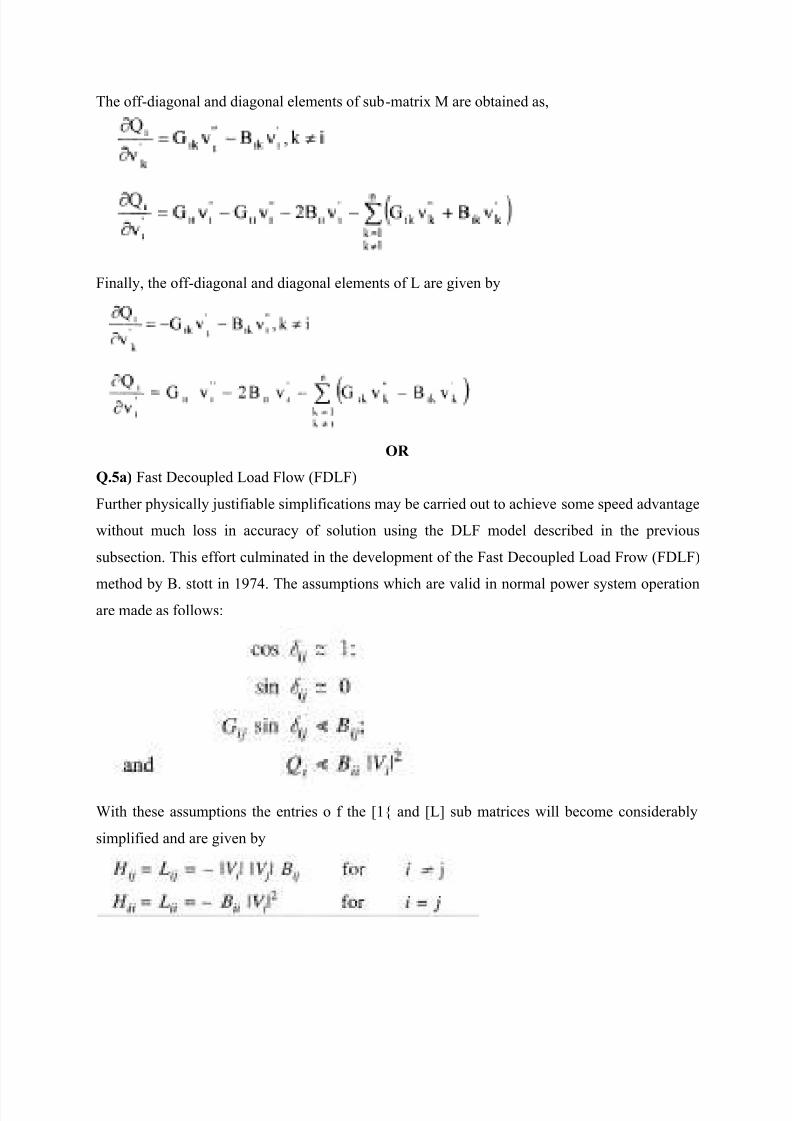
The off-diagonal and diagonal elements of sub-matrix M are obtained as,
Finally, the off-diagonal and diagonal elements of L are given by
OR
Q.5a) Fast Decoupled Load Flow (FDLF)
Further physically justifiable simplifications may be carried out to achieve some speed advantage
without much loss in accuracy of solution using the DLF model described in the previous
subsection. This effort culminated in the development of the Fast Decoupled Load Frow (FDLF)
method by B. stott in 1974. The assumptions which are valid in normal power system operationare made as follows:
With these assumptions the entries o f the [1{ and [L] sub matrices will become considerably
simplified and are given by
8/12/2019 Power Ssytem Analysis Solution VII Sem 2013
http://slidepdf.com/reader/full/power-ssytem-analysis-solution-vii-sem-2013 19/19
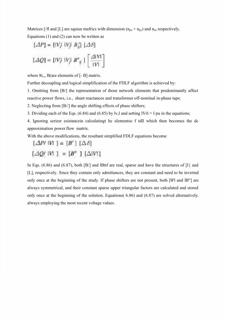
Matrices [/fl and [L] are squiue mafrics with dimension (n pe + n py) and nrn respectively.
Equations (1) and (2) can now be written as
where 8t,,, B(are elements of [- B] matrix.
Further decoupling and logical simplification of the FDLF algorithm is achieved by:
1. Omitting from [B/] the representation of those network elements that predominantly affect
reactive power flows, i.e., shunt reactances and transformer off-nominal in-phase taps;
2. Neglecting from [B//] the angle shifting effects of phase shifters;
3. Dividing each of the Eqs. (6.84) and (6.85) by lv,l and setting lVrl = I pu in the equations;
4. Ignoring seriesr esistancein calculatingt he elementso f tdll which then becomes the dc
approximation power flow matrix.
With the above modifications, the resultant simplified FDLF equations become
In Eqs. (6.86) and (6.87), both [B/] and lBttf are real, sparse and have the structures of [I{ and
[L], respectively. Since they contain only admittances, they are constant and need to be inverted
only once at the beginning of the study. If phase shifters are not present, both [B'l and lB"] are
always symmetrical, and their constant sparse upper triangular factors are calculated and stored
only once at the beginning of the solution. Equations( 6.86) and (6.87) are solved alternatively.
always employing the most recent voltage values.