Power Ring Film Capacitors & Integrated … · The evidence of “surprisingly low” overshoot is...
54
Over Half a Century of Expertise Power Ring Film Capacitors TM & Integrated Capacitor/Bus Structures For Wind & Solar
Transcript of Power Ring Film Capacitors & Integrated … · The evidence of “surprisingly low” overshoot is...

Over Half a Century of Expertise
Power Ring Film CapacitorsTM
& Integrated Capacitor/Bus Structures For Wind & Solar

Contents
• SBE Company Overview
• Power Ring Technology
• Power Capacitors and Integrated Cap/Bus offerings
Performance
Drop-in Capability
DC Link vs. Energy Storage
• Field Trial Simplicity

SBE, Inc.
• Making capacitors as Sprague since 1945 – independent since 1986 • Over 1 Billion capacitors manufactured • Headquartered in Barre, Vermont USA • Offices in Colorado, China and Netherlands • 240,000 unit annual Power Ring capacity

SBE Corporate Overview
Established: 1986, spin off of Sprague Electric. Capacitor production dates back to 1945 as Sprague. Locations: Headquarters, Manufacturing and R&D Center: Barre, Vermont
Application Engineering and Sales: Colorado, The Netherlands, and Xiamen China New plant constructed in 2010
Facilities: 53,000 square feet new facility with capacity for over 100,000 electric drive vehicles by 2012 China: engineering and assembly – 5,000 square feet Distributors: Future Electronics – worldwide
Richwood – China and Hong-Kong Ownership: Privately Held Corporation Markets: Transportation, Alternative Energy,
Medical/Laser, Military Key Customers: Emerson Electric,
Amway, Applied Energetics, Arens, Candela Laser, Continuum Laser, Dajun, SAIC, Taser, Woodward Governor, UQM, Cooper Lighting, DRS, Lockheed–Martin, Motorola, Honeywell, Miller Electric, Danfoss, Solectria, Dynapower

World Class Manufacturing and Engineering
• Large volume production capacity $19M DOE matching grant funded
expansion to supply capacitors for over 100,000 electric vehicles per year
Adapted for solar/wind as well • Robust procurement system assuring
lowest cost • Sourcing, engineering and sub-assembly
facility in China Plan in place to duplicate final
assembly/test in China as volume warrants
• Research, development and application Engineering in Colorado and Vermont Expertise in system integration and
optimization Industry leading testing capabilities

SBE Power Ring Film Capacitors™
Film Capacitor Technology Overview

SBE Power Ring Film Capacitors™
• Why film vs. other dielectrics such as ceramic and aluminum electrolytic
High reliability Capacitance stability over temperature and frequency Greater current carrying capability Low ESR/Losses Self-healing characteristics However, less capacitance and energy density

The Power Ring Advantage
• Film is film to all capacitor vendors. Everyone has access to the same global film suppliers.
• Key is to understand how to exploit the film properties to achieve its best performance.
Form Factor Film thickness Metallization

The Power Ring Advantage
• SBE has targeted the “Ring” form factor to provide the best possible performance and life.
Significant investment in proprietary winding technology. High value of knowledge through R&D. Performance at system integration level.

Power Ring Form Factor Advantage
Power Ring v. Traditional “Can” Style • Short current path = less resistance=less heat generation • Large surface area and short thermal path for optimized heat removal
• Lower t-rise for same ripple current
• Longer Life • Handle same current with fewer micro-Farads
Ideal for Large Monolithic Capacitors Lower Cost Fewer Failure Points Better Performance

Same capacitance (1.5mF) – more current capability and lifetime with a Power Ring

Lifetime with same ripple current rating (350A) at 55°C ambient

Compare Form Factor
1000 µF Polypropylene Film Capacitor(s) 200 A rms ripple at 5 kHz 55 C Boundary Conditions - 4x Cans in Parallel - Single Power Ring
89.6 C
55.8 °C
Power Ring 1000 µF 4 x 250 µF cans

SBE Temperature Rise
• 1000 µF, 600 V, 200 Arms ripple current @ 20 kHz
• Internal thermo-couples installed in the core of the winding

• Single monolithic winding: Better performance and fewer failure points than a bank of multiple smaller parts.
• Short current path provides very low ESR and losses (100 – 300 μΩ typical per part)
• Large thermal cross section area provides for efficient heat removal: Minimal hot spot temperature rise. Best possible current rating for given capacitance.
• Optimized terminal structure provides very low ESL (3 – 7nH typical)
• UL recognized
Key Technology Factors

• Highest current ratings per micro-Farad Reduce your DC Link micro-Farads and save cost and volume Greatly increase you system’s maximum safe current rating with the existing cost
and volume budget (double power – same cost)
• Reduce your cooling needs with less dissipated losses Reduce cost Increase power density for a given cooling design Reduce volume
• Increase your semiconductor’s safe, usable voltages Lowest ESL/eliminate snubbers Get more power from your selected IGBT vendor product
Utilize 1000V bus voltage with 1200V die
Reduce performance compromises in your driver architecture
System Benefits

Cap = 1500µF Voltage = 1100V ESR = 300µΩ ESL < 15nH Current – 350A Life 200,000 hrs (50°C) Price 1000+ = $245
SBE 700D590 Power Ring

Power Ring – Built for Life (example of a single 1500µF capacitor)
• Low ESR < 300µΩ • Low Thermal
Resistance • Lowest possible
hotspot temperature per Ampere of ripple current = long life

Compare ESL
Inductance Contribution
4x 250µF Cans Typical Bus
1000µF Power Ring Optimized Bus
IGBT 10nH 10nH
IGBT Interconnect 7nH 3nH
Bus 5nH 5nH
Capacitor 12.5nH 3.2nH
Total 34.5nH 21.2nH
40% less voltage overshoot = Increase DC bus voltage and harvest more kW per dollar invested in silicon
Even better ESL is possible with SBE integrated capacitor and bus technology
Fixed
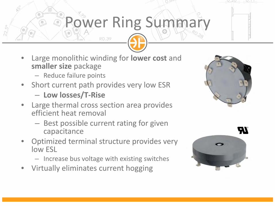
• Large monolithic winding for lower cost and smaller size package – Reduce failure points
• Short current path provides very low ESR – Low losses/T-Rise
• Large thermal cross section area provides efficient heat removal – Best possible current rating for given
capacitance • Optimized terminal structure provides very
low ESL – Increase bus voltage with existing switches
• Virtually eliminates current hogging
Power Ring Summary

The Power of the Ring
SBE Power Ring - Enabling state of the art integration

Integrated Cap/Bus
• SBE’s integrated bus/cap solutions offer the lowest ESL seen at the IGBT pins
• Maximize bus voltage • Lowest industry ESR and T-Rise means
longer life • Simplify manufacturing • Reduced failure points • Improve costs
Immediate reduction in capacitor costs Reduce manufacturing costs (reduced labor
and material costs) Reduce system maintenance costs
Protect and Maximize Your IGBT

Drop-in Replacements - Example
• Film to film drop-in • Integrated designs for drop-in
replacement • Protect your IGBT with lowest ESL • Lowest ESR and T-rise = long life • Improved cost, or • Up to twice the power in the
same space and cost
10pcs x 400uF/ 1100Vdc 300A rating at 55°C
4x 500uf/1100Vdc 450A rating at 55°C
How is this possible? Fewer Power Rings Can Handle the Full Bank Current

10 x 400μF -> 4000 μF bank
• Electronicon Example: E50 N13-404N50* • 1100V nominal • 300A total current possible (10 x 30A - cooling at 60°C) Current hogging limited?
• 40nH ESL each – total depends on assembly SBE estimates 25nH
• 0.4mΩ ESR – total bank • Lifetime expected at nominal voltage : • 100 000 hours *All information from Electronicon datasheet
Drop-in Replacements - Example

SBE Comparison Example: 2 x 700D590
2pcs x 1500 μF/ 1100Vdc Total:3000 μF/1100Vdc
Electrical description
• 2 x 1500μF -> 3000 μF bank • 1100V nominal • More than 700A continuous
and 1000A+ peak • 15nH ESL at IGBT terminals • 0.12mΩ ESR • Lifetime expected at
nominal voltage > 200,000 hours
• Similar W x L dimensions as 4000 μF Electronicon bank

SBE Drop-in Success Story
• Approached by customer experiencing field failures and looking for design improvements
• SBE proposed two separate options for customer consideration

SBE Drop-in Success Story
Half cut away - 2600µF 1500Vdc Capacitor - full view external
• The Problem Current hogging at certain capacitor sections Catastrophic field failures Expensive vs. power

• What’s good can be bad! The evidence of “surprisingly low” overshoot is not good fortune. It is usually evidence that one cap is dominating the low impedance path providing an
abnormal ESL vs expected but also filtering more current than planned. The “current hogging” cap is almost always the first to fail and the weak link.
• SBE can find this by simulating, doing passive “ring out” and overshoot tests and comparing the results. Wide discrepancies in your existing system are predicting failure points in the field.
• Power Ring assemblies show very little current hogging in typical examples with balanced IGBT connection points
Current Hogging

SBE Drop-in Success Story
• SBE Basic Solution • Match terminal structure • Improved but “compromise” ESL • Current distribution significantly better than original cap • Current hogging issue resolved but not optimized
2600µF 1500Vdc

SBE Drop-in Success Story
• SBE Optimized Solution – Two windings with crown terminals for uniform current
distribution - 2600µF 1500Vdc, 50% more power – Best-in-class ESL – Eliminated current hogging – Not terminal-to-terminal match but bus structure and volume “drop in”

• Outcomes: – SBE successfully replaced a 10 section traditional film
capacitor system with a 2 Power Ring solution – Customer opted for the basic solution for quick drop-in
adoption with existing terminal connections – Customer has known optimized solution for performance
upgrades during future design cycle with SBE unique terminal system
SBE Drop-in Success Story

Fully Integrated – Optimized Design
• Next Iteration – Integrated capacitor/bus structure
• Lowest possible ESL – enables 1200V IGBT with 1000V bus • Fewer failure points • Further cost reduction over original designs but 50% more power • 2600µF 1500Vdc – 400kW

Other SBE Optimized Integrated Solutions
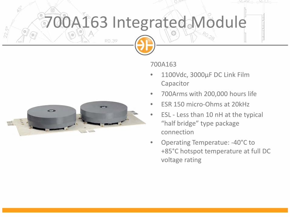
700A163 Integrated Module
700A163 • 1100Vdc, 3000μF DC Link Film
Capacitor • 700Arms with 200,000 hours life • ESR 150 micro-Ohms at 20kHz • ESL - Less than 10 nH at the typical
“half bridge” type package connection
• Operating Temperatue: -40°C to +85°C hotspot temperature at full DC voltage rating

4400uf 1100vdc Example Using Half Bridges
A 500kW – long life – low cost system

3000uf/1100vdc Example Using Half Bridges
A 500kW low cost – long life system

1500µF 700Vdc Example Conforming to Existing Customer space
A 250kw low cost – long life system

3 x 1500µF 1100Vdc Example “Half Bridge per Phase”
Confidential and Proprietary
A 500kW low cost – long life – flexible system

• Much higher current ratings per micro-Farad Reduce your DC Link micro-Farads and save cost and volume Greatly increase your system’s maximum safe current rating with the existing
cost and volume budget (double power – same cost)
• Reduce your cooling needs with less dissipated losses Reduce cost Increase Power Density for a given cooling design Reduce volume
• Increase your semiconductor’s safe, usable voltages Get more power from your selected IGBT vendor product
Utilize 1000V bus voltage with 1200V die Without the use of snubber capacitors or other additional hardware
Reduce performance compromises in your driver architecture
System Benefits Summary

SBE Bank HardenerTM The Best of Both Worlds

• Where capacitor bank volume/energy storage is a necessary value for your system
• Use the superior RMS current handling capability of the Power Ring to provide most of the current, giving the rest of the storage bank a “light ride”
• Depends on the capacitor “ratio” and the relative ESRs The worse the ESR, the better the effect
• More supply chain flexibility and cost opportunities
• Bus structure can “manipulate” the effect
SBE’s Bank Hardener™

SBE’s Bank Hardener™
• SBE’s Bank Hardener™ offers the best of both worlds – The energy storage capacity of Aluminum Electrolytic and the ripple current capability of Film
• Improve Cost Immediate reduction in capacitor costs Reduce manufacturing costs (reduced labor and material costs) Reduce maintenance costs
• Low T-rise, Increase Life The designed T-rise in the Electrolytic bank is greatly reduced
• Reduce Failure Points • Increase Inverter Power • Smaller Form Factor or • Drop-in Replacement as needed

SBE’s Bank Hardener™
SBE’s Bank Hardener™ - The Next Step in Capacitor Technology
Without Bank Hardener: • 36,000 µF • 1500Vdc • 400Arms • 120,000 hour lifetime
Increase life and/or increase inverter power with fewer capacitors
With Bank Hardener: • 19,500 µF
• AE bank reduced by ½ • Add 1,500 µF Power Ring Bank
Hardener • 1500Vdc • 400Arms • 120,000 hour lifetime

SBE’s Bank Hardener™
SBE’s Bank Hardener™ - Spend Less and Get More!
• Power Rings™ take an increasing amount of current as frequency increases
• Protects aluminum electrolytic caps and increases life

• The “low pass filter” effect of the bank hardener is applied to the entire spectral content of the switching artifacts of the inverter A significant percentage of the energy is occurring at 3, 5, 7 and 9x harmonics of the primary
switching frequency The aluminum electrolytics are highly sensitive to life degradation at these higher harmonics
SBE’s Bank Hardener™

SBE’s Bank Hardener™ Equivalent Switching Frequency

SBE’s Bank Hardener™ The desired results
SBE’s Bank Hardener™ Spend Less and Increase Life

SBE’s Bank Hardener™
• Resonance can be a serious problem • The bank hardener is designed as a system to
eliminate this issue – Taper impedances in the bus and interconnections – Make certain that resonant frequencies are not sitting on
top switching harmonics • Electrolytic resonance is pushed well beyond 100kHz
where there is not much energy • Film capacitor is rated for the total ripple current over
the full frequency spectrum

Example Bank Hardener
• 3x 400µF, 1100V power rings and 1.8mF electrolytic bank
• 230Arms • Each 400µF power ring is rated at 127Arms
– The electrolytics limit the life of this bank

Example Bank Hardener
• Add 1.2mF film capacitor to harden existing 1.8mF electrolytic bank

Minimum Film Cap
• 1100V, 750µF capacitor can manage 230A ripple current
• Volume of 1000 - $145

SBE’s Bank Hardener™ Flexible Implementation Examples
SBE’s Bank Hardener™ Spend Less and Increase Life
• Integrate high performance film capacitors on a bus structure
• Tightly integrated with the switch elements
• Low ESL and minimal current hogging • If additional capacitance is needed,
consider a “side-car” bank of electrolytic cans to provide slow energy storage
• “Side-car” bank concept has better performance if connection to power ring has higher impedance
• All designs can be validated by simulation

Summary
SBE technology enables: Reduced Costs
Immediate reduction in capacitor costs Reduced manufacturing costs (reduced labor and material costs) Consolidated Supply Chain (Up-Integration and source flexibility) Reduced system maintenance costs and downtime
Increased Reliability Low ESR (Low T-rise = Increased Life) Reduced Failure Points Designed out resonance concerns
Increased Inverter Power Lower ESL = Maximize IGBT efficiency Higher Ripple Current in the same cap bank size
Drop-In replacements System Optimization for next generation product launches

Try a Power Ring™
• SBE Test Kits (see the performance first hand) SBE provides test kits with adaptors for a variety of IGBTs
Vertical Test Kits Horizontal Test Kits
• SBE’s advanced simulation and testing tools can accurately measure: ESL Temperature Rise (and thus accurately predict life) Overshoot
• Integrated Capacitor/Bus design services & procurement • Talk to our world class design staff and obtain the benefits!