POWER QUALITY, LHC EARTHING AND CABLE INSTALLATION - CERN · POWER QUALITY, LHC EARTHING AND CABLE...
27
POWER QUALITY, LHC EARTHING AND CABLE INSTALLATION K. KAHLE, TS-EL LHC machine EMC Workshop 25 th Nov. 2004 1. Definition of Power Quality and Network Disturbances 2. Statistics 2003 3. Harmonics 4. LHC Engineering Specification 5. LHC earthing system 6. LHC cable installations 7. Conclusions
-
Upload
truongtuyen -
Category
Documents
-
view
225 -
download
1
Transcript of POWER QUALITY, LHC EARTHING AND CABLE INSTALLATION - CERN · POWER QUALITY, LHC EARTHING AND CABLE...
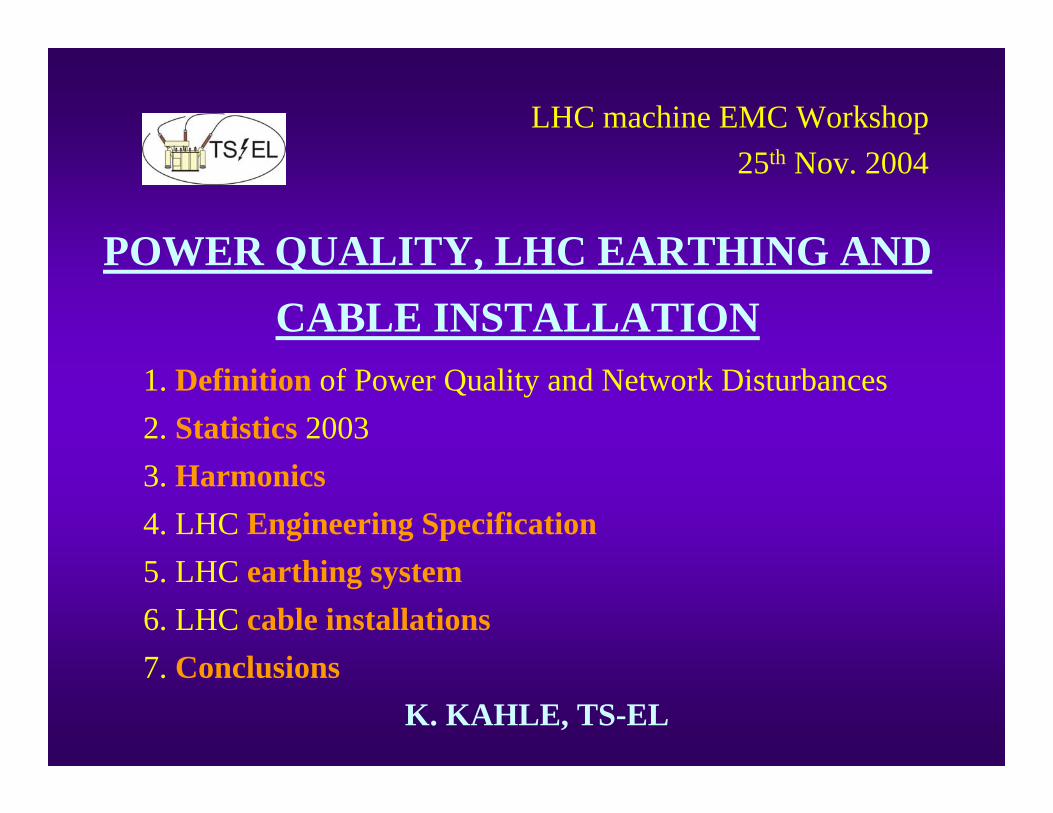
POWER QUALITY, LHC EARTHING AND CABLE INSTALLATION
K. KAHLE, TS-EL
LHC machine EMC Workshop 25th Nov. 2004
1. Definition of Power Quality and Network Disturbances2. Statistics 20033. Harmonics4. LHC Engineering Specification5. LHC earthing system6. LHC cable installations7. Conclusions
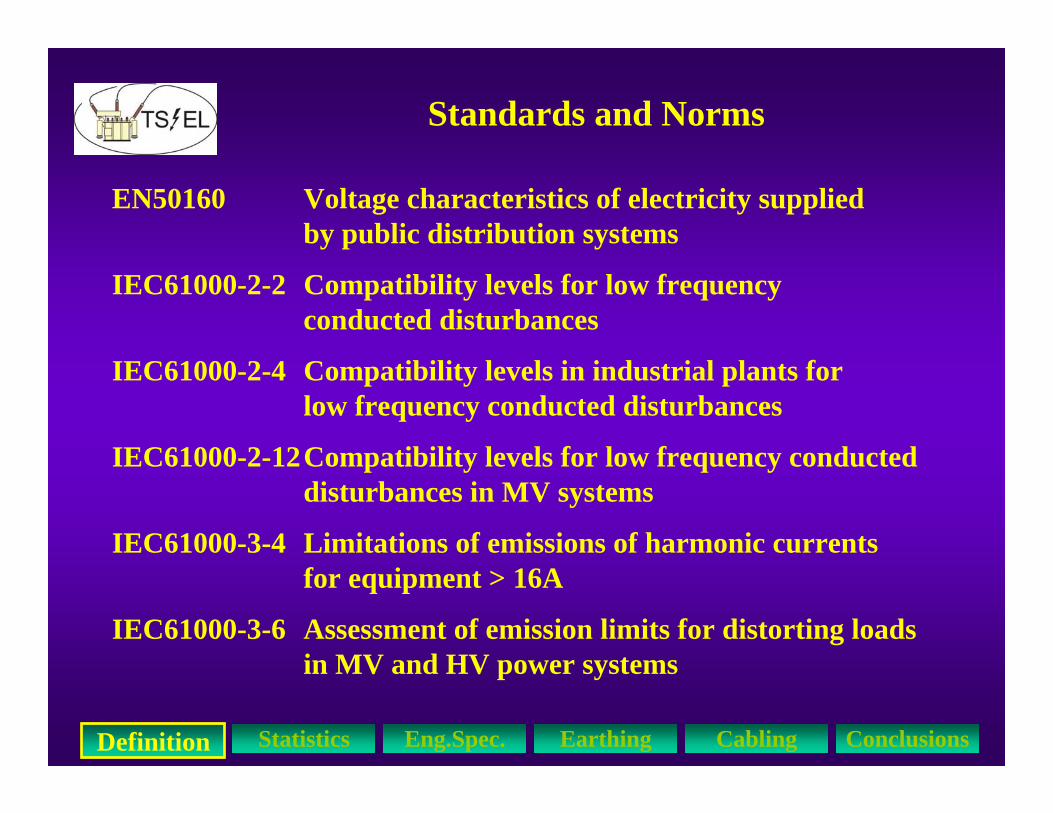
Standards and Norms
EN50160 Voltage characteristics of electricity supplied by public distribution systems
IEC61000-2-2 Compatibility levels for low frequency conducted disturbances
IEC61000-2-4 Compatibility levels in industrial plants for low frequency conducted disturbances
IEC61000-2-12Compatibility levels for low frequency conducted disturbances in MV systems
IEC61000-3-4 Limitations of emissions of harmonic currents for equipment > 16A
IEC61000-3-6 Assessment of emission limits for distorting loads in MV and HV power systems
Definition Statistics Eng.Spec. Earthing Cabling Conclusions
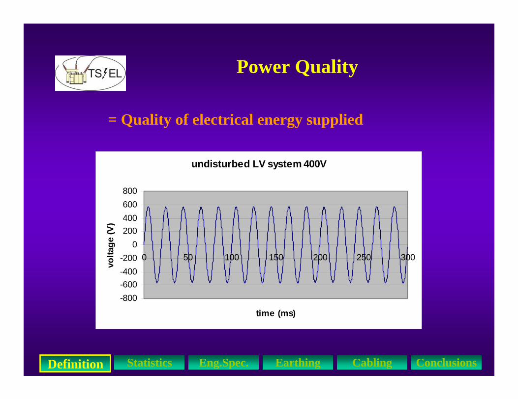
Power Quality
= Quality of electrical energy supplied
Definition Statistics Eng.Spec. Earthing Cabling Conclusions
undisturbed LV system 400V
-800-600-400-200
0200400600800
0 50 100 150 200 250 300
time (ms)
volta
ge (V
)
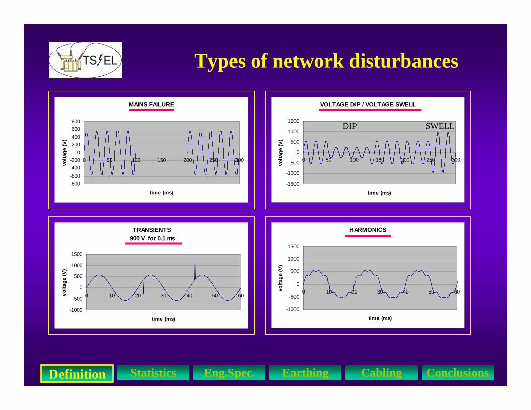
VOLTAGE DIP / VOLTAGE SWELL
-1500
-1000
-500
0
500
1000
1500
0 50 100 150 200 250 300
time (ms)
volta
ge (V
)
MAINS FAILURE
-800-600-400-200
0200400600800
0 50 100 150 200 250 300
time (ms)
volta
ge (V
)
HARMONICS
-1000
-500
0
500
1000
1500
0 10 20 30 40 50 60
time (ms)
volta
ge (V
)
Types of network disturbances
TRANSIENTS 900 V for 0.1 ms
-1000
-500
0
500
1000
1500
0 10 20 30 40 50 60
time (ms)
volta
ge (V
)
DIP SWELL
Definition Statistics Eng.Spec. Earthing Cabling Conclusions

VOLTAGE DIP / VOLTAGE SWELL
-1500
-1000
-500
0
500
1000
1500
0 50 100 150 200 250 300
time (ms)
volta
ge (V
)
HARMONICS
-1000
-500
0
500
1000
1500
0 10 20 30 40 50 60
time (ms)
volta
ge (V
)
Types of network disturbances
TRANSIENTS 900 V for 0.1 ms
-1000
-500
0
500
1000
1500
0 10 20 30 40 50 60
time (ms)
volta
ge (V
)
DIP SWELL
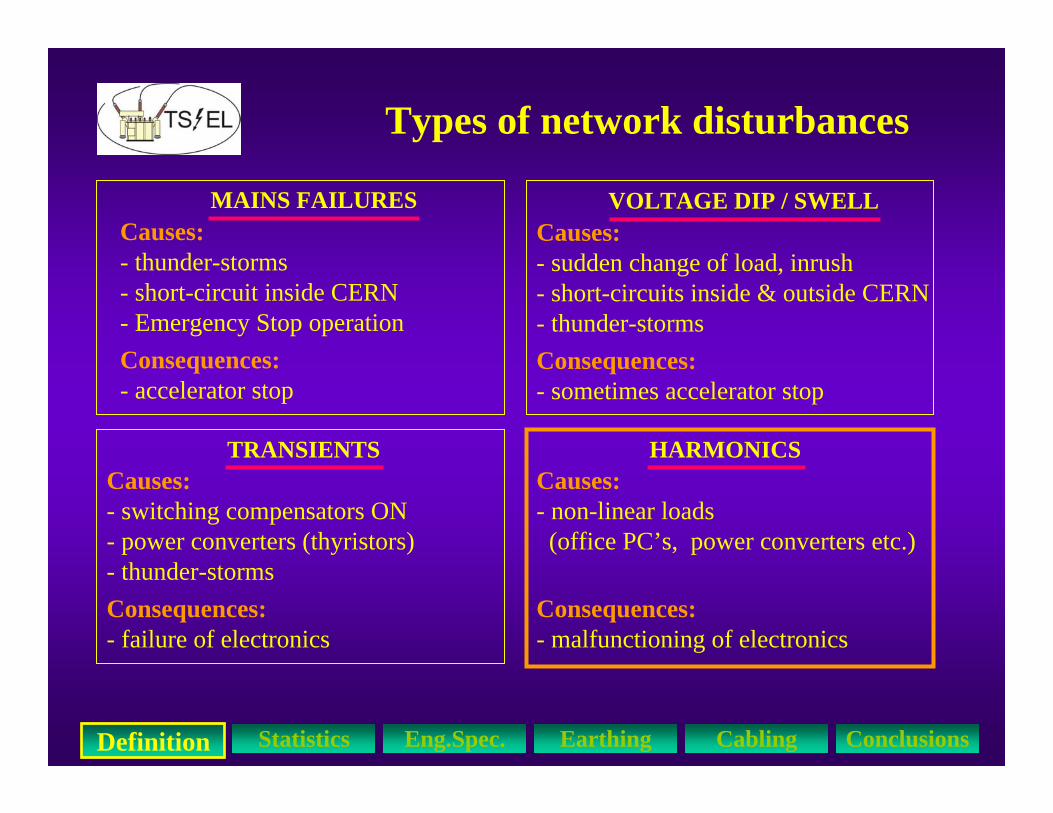
MAINS FAILURESCauses:- thunder-storms-short-circuit inside CERN- Emergency Stop operationConsequences:- accelerator stop
Definition Statistics Eng.Spec. Earthing Cabling Conclusions

HARMONICS
-1000
-500
0
500
1000
1500
0 10 20 30 40 50 60
time (ms)
volta
ge (V
)
Types of network disturbances
TRANSIENTS 900 V for 0.1 ms
-1000
-500
0
500
1000
1500
0 10 20 30 40 50 60
time (ms)
volta
ge (V
)
MAINS FAILURESCauses:- thunder-storms- short-circuit inside CERN- Emergency Stop operationConsequences:- accelerator stop
Causes:- sudden change of load, inrush- short-circuits inside & outside CERN- thunder-storms
VOLTAGE DIP / SWELL
Consequences:- sometimes accelerator stop
Definition Statistics Eng.Spec. Earthing Cabling Conclusions

HARMONICS
-1000
-500
0
500
1000
1500
0 10 20 30 40 50 60
time (ms)
volta
ge (V
)
Types of network disturbances
MAINS FAILURESCauses:- thunder-storms- short-circuit inside CERN- Emergency Stop operationConsequences:- accelerator stop
Causes:- sudden change of load, inrush- short-circuits inside & outside CERN- thunder-storms
VOLTAGE DIP / SWELL
Consequences:- sometimes accelerator stop
TRANSIENTS
Consequences:- failure of electronics
Causes:- switching compensators ON- power converters (thyristors)- thunder-storms
Definition Statistics Eng.Spec. Earthing Cabling Conclusions
Types of network disturbances
MAINS FAILURESCauses:- thunder-storms- short-circuit inside CERN- Emergency Stop operationConsequences:- accelerator stop
Causes:- sudden change of load, inrush- short-circuits inside & outside CERN- thunder-storms
VOLTAGE DIP / SWELL
Consequences:- sometimes accelerator stop
TRANSIENTS
Consequences:- failure of electronics
Causes:- switching compensators ON- power converters (thyristors)- thunder-storms
HARMONICSCauses:- non-linear loads (office PC’s, power converters etc.)
Consequences:- malfunctioning of electronics
Definition Statistics Eng.Spec. Earthing Cabling Conclusions
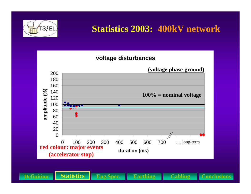
Statistics 2003: 400kV network
voltage disturbances
020406080
100120140160180200
0 100 200 300 400 500 600 700 800 900 1000duration (ms)
ampl
itude
(%)
100% = nominal voltage
red colour: major events(accelerator stop)
…. long-term
StatisticsDefinition Eng.Spec. Earthing Cabling Conclusions
(voltage phase-ground)

Statistics 2003: 18kV network
voltage disturbances
020406080
100120140160180200
0 100 200 300 400 500 600 700 800 900 1000duration (ms)
ampl
itude
(%)
100% = nominal voltage
red colour: major events(accelerator stop)
…. long-term
StatisticsDefinition Eng.Spec. Earthing Cabling Conclusions
(voltage phase-ground)
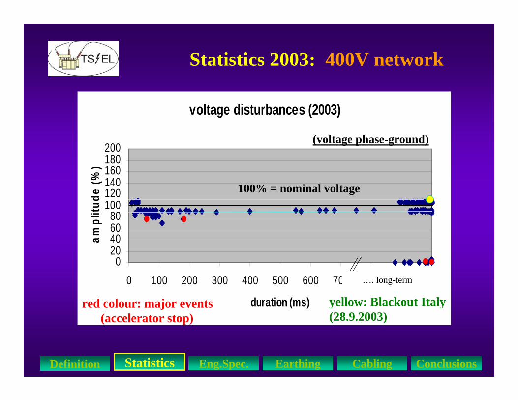
Statistics 2003: 400V network
voltage disturbances (2003)
020406080
100120140160180200
0 100 200 300 400 500 600 700 800 900 1000
duration (ms)
ampl
itude
(%)
100% = nominal voltage
red colour: major events(accelerator stop)
yellow: Blackout Italy(28.9.2003)
…. long-term
StatisticsDefinition Eng.Spec. Earthing Cabling Conclusions
(voltage phase-ground)

Worst-case Undervoltages 0.4kV (2003)
StatisticsDefinition Eng.Spec. Earthing Cabling Conclusions
thunder-stormStation ERD1/8R70 ms- 28 %
thunder-stormBooster SVC110 ms- 30 %
thunder-stormBuildg. 2260, PA2130 ms- 32 %
thunder-stormStation ERD1/8R110 ms- 34 %
short circuit 18 kVBuildg. 2660, PA6180 ms- 71 %
CauseLocationDurationDip
(voltages phase-ground)

Worst-case Overvoltages 0.4kV (2003)
StatisticsDefinition Eng.Spec. Earthing Cabling Conclusions
(voltages phase-ground)
unknownEAD345/PA210 ms+ 13 %
unknownEYS01/PA650 ms+ 16 %
unknownEYS01/PA650 ms+ 18 %
unknownESD1/BK630 ms+ 20 %
unknownESD1/BK630 ms+ 25 %
CauseLocationDurationSwell
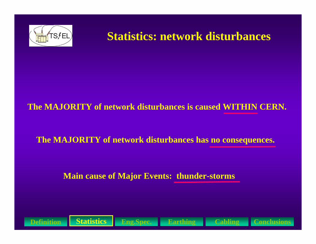
Statistics: network disturbances
The MAJORITY of network disturbances is caused WITHIN CERN.
The MAJORITY of network disturbances has no consequences.
Main cause of Major Events: thunder-storms
StatisticsDefinition Eng.Spec. Earthing Cabling Conclusions
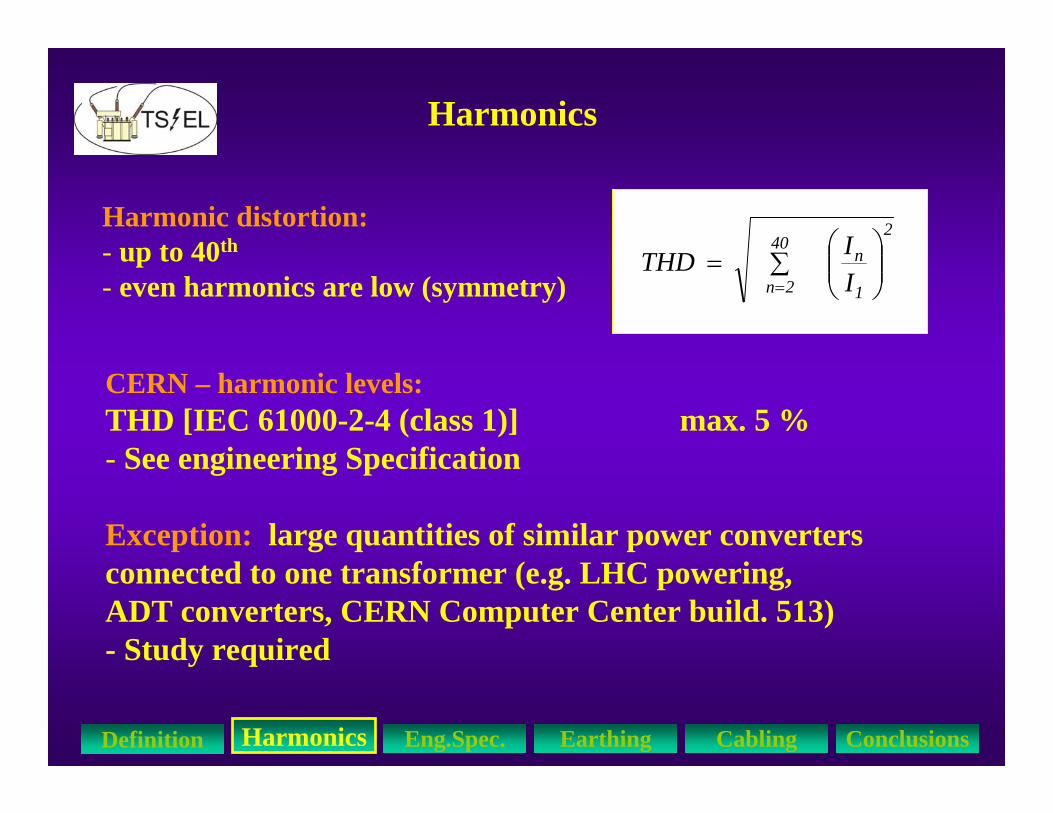
Harmonics
Harmonic distortion:- up to 40th
- even harmonics are low (symmetry)
CERN – harmonic levels: THD [IEC 61000-2-4 (class 1)] max. 5 %- See engineering Specification
Exception: large quantities of similar power convertersconnected to one transformer (e.g. LHC powering, ADT converters, CERN Computer Center build. 513)- Study required
∑ ⎟⎟⎠
⎞⎜⎜⎝
⎛=
=
40
2n 1
n2
IITHD
HarmonicsDefinition Eng.Spec. Earthing Cabling Conclusions

Harmonics
Harmonic emission (non-linear loads):- 6-pulse thyr. power converters: 5, 7, 11, 13th
- 12-pulse thyr. power converters: 11, 13, 23, 25th
- single-phase PC’s: 3, 5, 7th
(If 3rd harmonics: Neutral current can exceed phase current!)
Remedies: - Limit harmonic emission of load (IEC61000-3-2 and 3-4)- 12pulse instead of 6pulse- reduce network impedance (cables, special transformer)- harmonic filters (Static Var Compensator 18kV)- transformers: earthed screen between HV/LV winding - separate machine and general services !
HarmonicsDefinition Eng.Spec. Earthing Cabling Conclusions

LHC Engineering Specification
Nominal voltage 400/230 VMaximum operating variations +/-10 %
Nominal frequency 50 HzMaximum variations +/-0.5 Hz
Total Harmonic Distortion, THD 5 %
Voltage unbalance 2 %
Eng. Spec. Definition Statistics Earthing Cabling Conclusions

LHC Engineering Specification
Transient voltage disturbances:
Peak mains surges 1200 V for 0.2 ms
Mains over voltage, typical value 50% of Un for 10 ms
Voltage drops 50 % of Un, typically 100 ms
Eng. Spec. Definition Statistics Earthing Cabling Conclusions
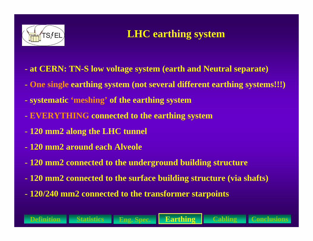
LHC earthing system
EarthingDefinition Statistics Eng. Spec. Cabling Conclusions
- at CERN: TN-S low voltage system (earth and Neutral separate)
- One single earthing system (not several different earthing systems!!!)
- systematic ‘meshing’ of the earthing system
- EVERYTHING connected to the earthing system
- 120 mm2 along the LHC tunnel
- 120 mm2 around each Alveole
- 120 mm2 connected to the underground building structure
- 120 mm2 connected to the surface building structure (via shafts)
- 120/240 mm2 connected to the transformer starpoints

LHC earthing system (tunnel)
1)
2)
3)
TI2, TI8, String 2
EarthingDefinition Statistics Eng. Spec. Cabling Conclusions
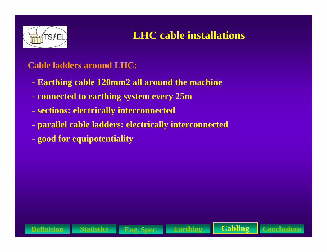
LHC cable installations
Cable ladders around LHC:
- Earthing cable 120mm2 all around the machine- connected to earthing system every 25m- sections: electrically interconnected - parallel cable ladders: electrically interconnected- good for equipotentiality
CablingDefinition Statistics Eng. Spec. Earthing Conclusions
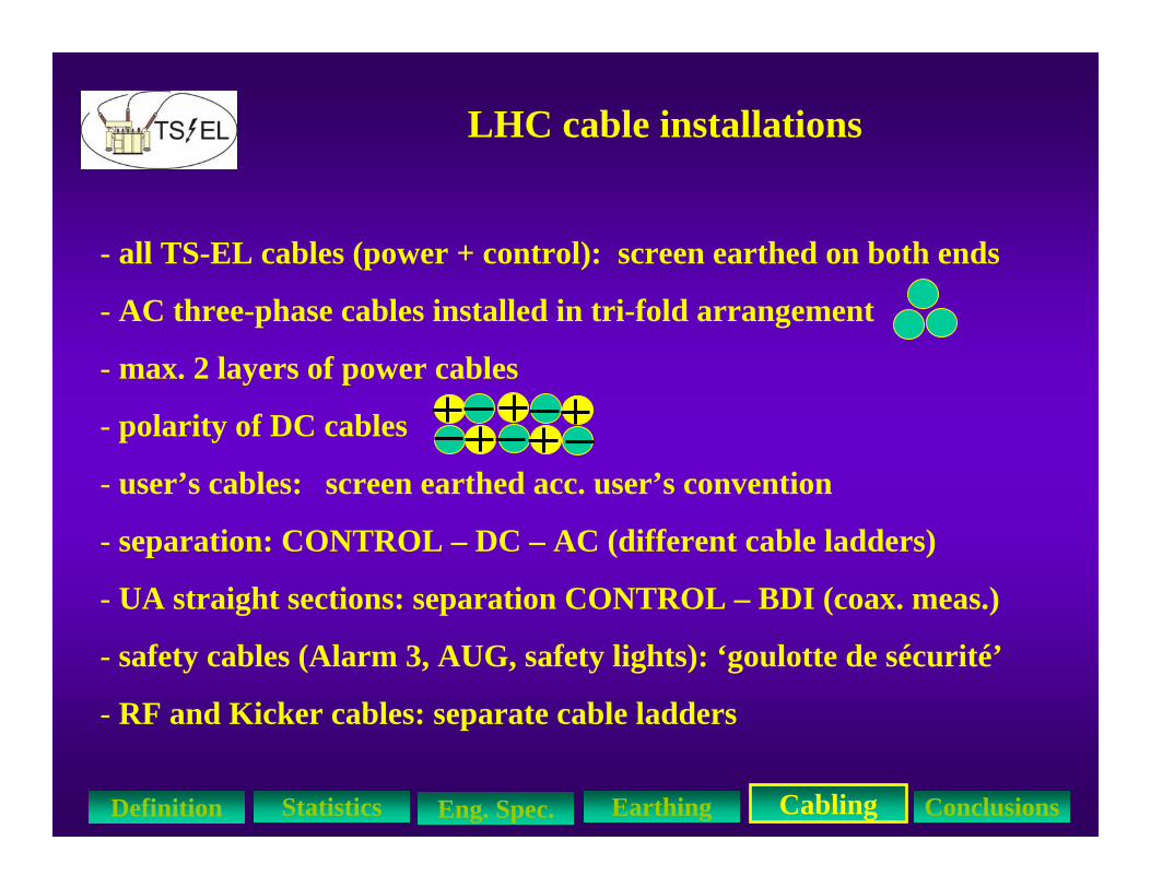
LHC cable installations
- all TS-EL cables (power + control): screen earthed on both ends
- AC three-phase cables installed in tri-fold arrangement
- max. 2 layers of power cables
- polarity of DC cables
- user’s cables: screen earthed acc. user’s convention
- separation: CONTROL – DC – AC (different cable ladders)
- UA straight sections: separation CONTROL – BDI (coax. meas.)
- safety cables (Alarm 3, AUG, safety lights): ‘goulotte de sécurité’
- RF and Kicker cables: separate cable ladders
CablingDefinition Statistics Eng. Spec. Earthing Conclusions
Cable screens
General rule: earthing of cable screens on both sides !
- Power cables HV, LV- HF and LF coax. cables- measurement cables- signal cables
Exception, if 5 conditions are fulfilled simultaneously:-See Alain CHAROY - e.g. Cryo temperature measurement CERNOX- e.g. Huba Piezo Gauge
CablingDefinition Statistics Eng. Spec. Earthing Conclusions
Transient network disturbances:
Conclusions 1/3
ConclusionDefinition Statistics Eng. Spec. Earthing Cabling
* MAJORITY of network disturbances is caused WITHIN CERN
* MAJORITY has no consequences
* Main cause of Major Events: thunder-storms
* To assure the functioning of equipment through disturbances, definition of tolerance levels for user’s equipment:
LHC Engineering Spec. EDMS113154 (28.07.2000) “Main Parameters of the LHC 400/230V Distribution System”
Earthing System:* Equipotentiality
* as many interconnections as possible (mesh)
* as many loops as possible (mesh)
* all buildings interconnected
* one single earthing system for EVERYTHING
* connected to the building structure
* connected to all metallic parts (rails, racks, platforms)
* connected to all transformer starpoints
* Earth connections of equipment as short as possible
ConclusionsDefinition Measurem. Statistics ReliabilitySimulation
Conclusions 2/3
* Separation of CONTROL – AC – DC cables
* Screen earthed on both ends
* AC 3phase cables in tri-fold
Cabling:
ConclusionsDefinition Measurem. Statistics ReliabilitySimulation
Conclusions 3/3

ConclusionsDefinition Measurem. Statistics ReliabilitySimulation
Questions ?
Thank you.
![Untitled-1 [] · (1) Cable Gland &Accessories (2) Earthing Accessories (3) Cable Lugs (4) Conduit Fittings. This -industry is renowned and highly reputed for its quality products](https://static.fdocuments.us/doc/165x107/5f959bb7511a9e0491741494/untitled-1-1-cable-gland-accessories-2-earthing-accessories-3-cable.jpg)