Power products - brodinger.atbrodinger.at/pdf/DIESEL-01_Stromerzeuger_Uebersicht.pdf · TELYS...
8
Subsidiaries ARGENTINA SDMO ARGENTINA S.A. TEL. +54 11 48363511 - FAX +54 11 48363516 BELGIUM SDMO NV/SA TEL. +32 3 646 04 15 - FAX +32 3 646 06 25 BRAZIL SDMO DO BRAZIL TEL. +55 (11)4390 8434 - FAX +55 (11)4390 8434 SPAIN SDMO INDUSTRIES IBERICA TEL. +34 902 30 56 56 - FAX +34 93 580 31 36 UNITED STATES SDMO GENERATING SETS TEL. +1 305 863 00 12 - FAX +1 305 863 97 81 UNITED KINGDOM SDMO ENERGY LTD TEL. +44 (0)1932 345 777 - FAX +44 (0)1932 350 033 NIGERIA SDMO LAGOS TEL +234 (0)1 776 95 95 - FAX + 33 (0)1 72 27 55 62 Offices ALGERIA SDMO ALGER TEL. +213 21 92 55 84 - FAX +213 21 92 47 76 DUBAI SDMO MIDDLE EAST TEL. + 971 50 294 96 94 - FAX +33 1 722 755 75 SDMO Industries - 12 bis rue de la villeneuve CS 92 848 - 29 228 Brest Cedex 2 - France Tel. +33 (0)2 98 41 41 41 - Fax +33 (0)2 98 41 63 07 www.sdmo.com Photo credit: SDMO - Guillaume Team 4668-10.06.L Power products ENGLISH PPRINT/GB-2007/1 50HZ 60HZ 7.5kVA - 630kVA 11kWe - 550kWe ��������������� ����������������������
Transcript of Power products - brodinger.atbrodinger.at/pdf/DIESEL-01_Stromerzeuger_Uebersicht.pdf · TELYS...
Subsidiaries
ARGENTINASDMO ARGENTINA S.A.
TEL. +54 11 48363511 - FAX +54 11 48363516
BELGIUMSDMO NV/SA
TEL. +32 3 646 04 15 - FAX +32 3 646 06 25
BRAZILSDMO DO BRAZIL
TEL. +55 (11)4390 8434 - FAX +55 (11)4390 8434
SPAINSDMO INDUSTRIES IBERICA
TEL. +34 902 30 56 56 - FAX +34 93 580 31 36
UNITED STATES SDMO GENERATING SETS
TEL. +1 305 863 00 12 - FAX +1 305 863 97 81
UNITED KINGDOMSDMO ENERGY LTD
TEL. +44 (0)1932 345 777 - FAX +44 (0)1932 350 033
NIGERIASDMO LAGOS
TEL +234 (0)1 776 95 95 - FAX + 33 (0)1 72 27 55 62
Offices
ALGERIASDMO ALGER
TEL. +213 21 92 55 84 - FAX +213 21 92 47 76
DUBAISDMO MIDDLE EAST
TEL. + 971 50 294 96 94 - FAX +33 1 722 755 75
SDMO Industries - 12 bis rue de la villeneuveCS 92 848 - 29 228 Brest Cedex 2 - France
Tel. +33 (0)2 98 41 41 41 - Fax +33 (0)2 98 41 63 07www.sdmo.com
Pho
to c
red
it: S
DM
O -
Gu
illau
me
Team
4668
-10.
06.L Po
wer p
rodu
cts
ENGLISH
PPRINT/GB-2007/1
50HZ 60HZ7.5kVA - 630kVA11kWe - 550kWe
�������������������������������������
SDMO is recognised as one of the best manufacturers of gene ra t ing sets in the world. SDMO has channelled all its energy into designing a range which is both highly-competitive and high-performance, the largest range available on the market. As a response to the increasingly precise nature of your energy requirements, which relate directly to the special traits of your particular industry, SDMO is devoting the majority of its resources to the continuous improvement of its range and services.
The result of a strategy focussed on a single industry: our exacting professionalism provides you with a reliable source of energy, complying with the strictest of standards. The pioneering mindset of their teams, and the mastery and flexibility of their production methods mean that SDMO is constantly innovating. The proximity of their distribution network and dynamism of their customer services policy enable SDMO to be a powerful force and provide the basis of the company's values.
SDMO, the source of energy for your comfort and safety. SDMO, providing the energy that links mankind.
PPRINT/GB-2007/1
50HZ 60HZ7.5kVA - 630kVA11kWe - 550kWe
A powerful response whatever the energy required
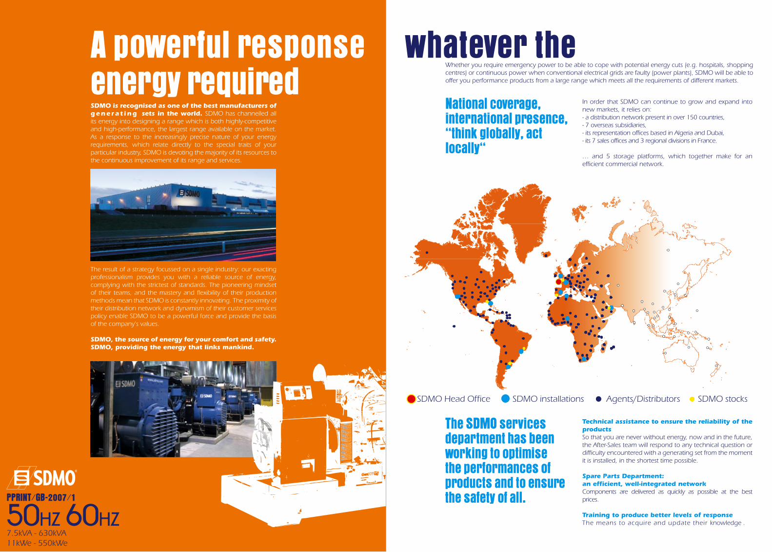
Whether you require emergency power to be able to cope with potential energy cuts (e.g. hospitals, shopping centres) or continuous power when conventional electrical grids are faulty (power plants), SDMO will be able to offer you performance products from a large range which meets all the requirements of different markets.
National coverage, international presence, ‘‘think globally, act locally‘‘
In order that SDMO can continue to grow and expand into new markets, it relies on:- a distribution network present in over 150 countries,- 7 overseas subsidiaries,- its representation offices based in Algeria and Dubai,- its 7 sales offices and 3 regional divisions in France.
… and 5 storage platforms, which together make for an efficient commercial network.
Technical assistance to ensure the reliability of the productsSo that you are never without energy, now and in the future, the After-Sales team will respond to any technical question or difficulty encountered with a generating set from the moment it is installed, in the shortest time possible.
Spare Parts Department: an efficient, well-integrated networkComponents are delivered as quickly as possible at the best prices.
Training to produce better levels of responseThe means to acquire and update their knowledge .
��������������������������������������������������������������������������������������������
The SDMO services department has been working to optimise the performances of products and to ensure the safety of all.
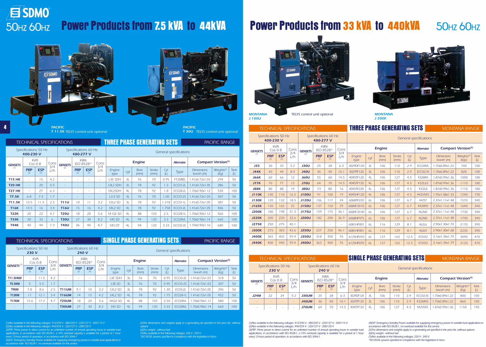
Power Products from 7.5 kVA to 44kVA
PACIFICT 11.5K
PACIFIC T 30U
TECHNICAL SPECIFICATIONS PACIFIC RANGE
(1)Also available in the following voltages: 415/240 V - 380/220 V - 220/127 V - 200/115 V(2)Also available in the following voltages: 440/254 V - 220/127 V - 208/120 V (3)PRP: Prime power in direct current for an unlimited number of annual operating hours in variable load applications, in accordance with ISO 8528-1, a 10% overload capacity is available for a period of 1 hour every 12-hour period of operation, in accordance with ISO 3046-1(4)ESP: Emergency Standby Power available for supplying emergency power in variable load applications in accordance with ISO 8528-1, no overload available for this service.
(5)The dimensions and weights apply to a generating set specified in the price list, without options
(6)Dry weight - without fuel (7)Also available in the following voltages: 220 V - 240 V *ISO 8528: powers specified in compliance with the legislation in force
Power Products from 33 kVA to 440kVA
MONTANA J 100U
MONTANA J 200K
THREE PHASE GENERATING SETSSpecifications 50 Hz
400-230 VSpecifications 60 Hz
480-277 VGeneral specifications
GENSETS
(1)
kVACos 0.8 Cons
3/4 L/h
GENSETS
(2)
kWeISO 8528* Cons
3/4 L/h
Engine Alternator Compact Version(5)
PRP (3)
ESP(4)
PRP (3)
ESP(4)
Engine type cyl Bore
(mm)Stroke(mm)
Cyl(L) Type Dimensions
lxwxh (m)Weights(6)
(kg)Tank (L)
T15 HK - 15 4.2 - - - - L3E SDH 3L 76 70 0.95 FT2MBS 1.41x0.72x1.03 294 50
T20 HK - 20 5.5 - - - - S3L2 SDH 3L 78 92 1.3 ECO3-2L 1.41x0.72x1.05 386 50
T27 HK - 27 6.3 - - - - S4L2SDH 4L 78 92 1.8 ECO28-2L 1.70x0.90x1.12 530 100
T7.5K 6.8 7.5 1.7 - - - - L3 E SD 3L 76 70 1.00 ECO3-2S 1.41x0.72x1.03 307 50
T11.5K 10.5 11.5 2.5 T11U 10 11 3.2 S3L2 SD 3L 78 92 1.318 ECO3-1L 1.41x0.72x1.05 387 50
T16K 14.5 16 3.4 T16U 15 16 4.2 S4L2 SD 4L 78 92 1.758 ECO3-2L 1.41x0.72x1.05 406 50
T22K 20 22 4.7 T20U 18 20 5.6 S4 Q2 SD 4L 88 103 2.5 ECO28-1L 1.70x0.90x1.12 560 100
T33K 30 33 6 T30U 27 30 8.2 S4S SD 4L 94 120 3.3 ECO28VL 1.70x0.90x1.14 660 100
T44K 40 44 7.3 T40U 36 40 8.7 S4S DT 4L 94 120 3.33 ECO32-3S 1.70x0.90x1.16 680 100
4
TECHNICAL SPECIFICATIONS PACIFIC RANGESINGLE PHASE GENERATING SETSSpecifications 50 Hz
230 VSpecifications 60 Hz
240 VGeneral specifications
GENSETS (7)
kVACos 0.8 Cons
3/4 L/h
GENSETS
kWeISO 8528* Cons
3/4 L/h
Engine Alternator Compact Version(5)
PRP (3)
ESP(4)
PRP (3)
ESP(4)
Engine type cyl Bore
(mm)Stroke(mm)
Cyl(L) Type Dimensions
lxwxh (m)Weights(6)
(kg)Tank (L)
T11.5HKM - 11.5 4.2 - - - - L3E SDH 3L 76 70 0.95 ECO3-2L 1.41x0.72x1.03 318 50
T5.5KM 5 5.5 1.7 - - - - L3E SD 3L 76 70 0.95 ECO3-2S 1.41x0.72x1.03 307 50
T9KM 7.8 8.6 2.5 T11UM 9.1 10 3.2 S3L2 SD 3L 78 92 1.30 ECO3-2L 1.41x0.72x1.05 396 50
T12KM 11 12.1 3.4 T16UM 14 15 4.2 S4L2 SD 4L 78 92 1.75 ECO28-1L 1.41x0.72x1.05 452 50
T17KM 15.6 17.2 4.7 T20UM 18 20 5.6 S4Q2 SD 4L 88 103 2.50 ECO28VL 1.70x0.90x1.12 580 100
- - - - T30UM 27 30 8.2 S4S SD 4L 94 120 3.33 ECO28VL 1.70x0.90x1.14 660 100
TECHNICAL SPECIFICATIONS MONTANA RANGETHREE PHASE GENERATING SETSSpecifications 50 Hz
400-230 VSpecifications 60 Hz
480-277 VGeneral specifications
GENSETS
(1)
kVACos 0.8 Cons
3/4 L/h
GENSETS(2)
kWeISO 8528* Cons
3/4 L/h
Engine Alternator Compact Version(5)
PRP (3)
ESP(4)
PRP (3)
ESP(4)
Engine type cyl Bore
(mm)Stroke(mm)
Cyl(L) Type Dimension
lxwxh (m)Weights(6)
(kgs)Tank (L)
J33 30 33 5.2 J30U 25 28 6.3 3029DF120 3L 106 110 2.9 ECO28VL 1.70x0.89x1.22 740 100
J44K 40 44 8.4 J40U 36 40 10.1 3029TF120 3L 106 110 2.9 ECO32-3S 1.70x0.89x1.22 820 100
J66K 60 66 12 J60U 55 60 14.5 4045TF120 4L 106 127 4.5 432M45 1.87x0.99x1.36 1000 180
J77K 70 77 12 J70U 64 70 14.5 4045TF120 4L 106 127 4.5 432L65 1.87x0.99x1.36 1110 180
J88K 80 88 14 J80U 73 80 16 4045TF220 4L 106 127 4.5 432L8 1.87x0.99x1.36 1110 180
J110K 100 110 16.5 J100U 91 100 19 4045HF120 4L 106 127 4.5 442VS45 1.95x1.08x1.33 1240 190
J130K 120 132 18.5 J120U 106 117 24 6068TF220 6L 106 127 6.7 442S7 2.37x1.11x1.48 1570 340
J165K 150 165 25 J150U 137 150 29 6068HF120-153 6L 106 127 6.7 442M95 2.37x1.11x1.48 1640 340
J200K 180 198 31.3 J175U 159 175 36.1 6068HF120-183 6L 106 127 6.7 462M3 2.37x1.11x1.48 1730 340
J220K 200 220 32.6 J200U 182 200 36.9 6068HF475 6L 106 127 6.7 462M5 2.37x1.11x1.48 1790 340
J275K 250 275 40.1 - - - - 6081HF001 6L 116 129 8.1 462L6 2.90x1.30x1.70 2170 390
J300K 275 303 42.6 J250U 227 250 46.1 6081HF001 6L 116 129 8.1 462L9 2.90x1.30x1.68 2235 390
J400K 365 402 59.4 J350U 318 350 76 6125HF070 6L 127 165 12.5 472VS2 3.16x1.34x1.79 3090 470
J440K 400 440 59.4 J400U 363 400 76 6125HF070 6L 127 165 12.5 472VS3 3.16x1.34x1.79 3120 470
TECHNICAL SPECIFICATIONS MONTANA RANGESINGLE PHASE GENERATING SETSSpecifications 50 Hz
230 VSpecifications 60 Hz
240 VGeneral specifications
GENSETS
(7)
kVACos 0.8 Cons
3/4 L/h
GENSETSkWe
ISO 8528* Cons 3/4 L/h
Engine Alternator Compact Version(5)
PRP (3)
ESP(4)
PRP (3)
ESP(4)
Engine type cyl Bore
(mm)Stroke(mm)
Cyl(L) Type Dimensions
lxwxh (m)Weights(6)
(kg)Tank (L)
J24M 22 24 5.2 J30UM 25 28 6.3 3029DF120 3L 106 110 2.9 ECO32-3S 1.70x0.89x1.22 800 100
- - - - J40UM 36 40 10.1 3029TF120 3L 106 110 2.9 432M45 1.70x0.89x1.22 860 100
- - - - J70UM 64 70 14.5 4045TF120 4L 106 127 4.5 442VS45 1.87x0.99x1.36 1150 190
(1)Also available in the following voltages: 415/240 V - 380/220 V - 220/127 V - 200/115 V(2)Also available in the following voltages: 440/254 V - 220/127 V - 208/120 V (3)PRP: Prime power in direct current for an unlimited number of annual operating hours in variable load applications, in accordance with ISO 8528-1, a 10% overload capacity is available for a period of 1 hour every 12-hour period of operation, in accordance with ISO 3046-1
(4)ESP: Emergency Standby Power available for supplying emergency power in variable load applications in accordance with ISO 8528-1, no overload available for this service(5)The dimensions and weights apply to a generating set specified in the price list, without options(6)Dry weight - without fuel (7)Also available in the following voltages: 220 V - 240 V *ISO 8528: powers specified in compliance with the legislation in force
50HZ 60HZ 50HZ 60HZ
TELYS control unit optional
TELYS control unit optional TELYS control unit optional
Basic and options
PACIFIC MONTANA
ATLANTICT11U/11.5/15H/20HT5.5/7.5/ 9/ 11.5
T12/16/17T20U/22
T27H/30U/33T40U/44
J24MJ30U/33J40U/44
J60U/66/70U/77J80U/88
J100U/110
J120U/130J150U/165J175U/200
J200U/220J250U/275
J300
J350J400J440
4 stroke water-cooled diesel engine • • • • • • • • •Mechanical adjustment • • • • • • • x x
Electronic adjustment x EN 01(1) EN 01 EN 01 EN 01 EN 01 EN 01 • •Standard air filter • • • • • • • • •
Air filter with interchangeable cartridge x EN 02(2) EN 02 EN 02 EN 02 EN 02 EN 02 EN 02 EN 02220/240 V preheating resistor EN 20 EN 20 EN 20 EN 20 EN 20 EN 20 EN 20 EN 20 EN 20
Control and interface unit (CIU) x x x x x x x x EN 22(6)
Single bearing alternator IP 23, T° class =H, insulation class H • • • • • • • • •Anti condensation resistor x x x x AL 01 AL 01 AL 01 AL 01 AL 01
Reinforced insulation x x x x AL 05 AL 05 AL 05 AL 05 AL 05Synchronizing CT coupling + 3 function regulator x x x x x o(5) o o o
AREP excitation x x x x AL 11 AL 11 AL11 AL 11 AL11PMG + Regulator x x x x AL 12 AL 12 AL 12 AL 12 AL 12
CE compliance of the control unit • • • • • • • • •Protective grille for hot parts CEL 02 CEL 02 CEL 02 CEL 02 CEL 02 CEL 02 CEL 02 CEL 02 CEL 02
CSA NRTL/C compliance CEL 03 CEL 03 CEL 03 CEL 03 CEL 03 CEL 03 CEL 03 CEL 03 CEL 03Power circuit breaker • • • • • • • • •
Mechanically welded chassis with antivibration suspension • • • • • • • • •Supplied in colour RAL 9005/5007 (black/blue) delivered in shrink-wrap film • • • • • • • • •
Supplied with oil and coolant -30°C • • • • • • • • •Oil drain tap + diesel or gas pipe • • • • • • • • •
Oil drainage pump EN 04 EN 04 EN 04 EN 04 EN 04 EN 04 EN 04 EN 05 EN 059 dB(A) silencer supplied separately • • • • • • • • •
9 dB(A) silencer not supplied EN 07 EN 07 EN 07 EN 07 EN 07 EN 07 EN 07 EN 07 EN 07Adaptable 9 dB(A) silencer (not compatible with CEL 02) EN 12 EN 12 EN 12 EN 12 EN 12 EN 12 x x x
29 dB(A) silencer supplied separately EN 08 EN 08 EN 08 EN 08 EN 08 EN 08 EN 08 EN 08 EN 0840 dB(A) silencer supplied separately EN 09 EN 09 EN 09 EN 09 EN 09 EN 09 EN 09 EN 09 EN 09
40 cm extension piece EN 13 EN 13 EN 13 EN 13 EN 13 EN 13 x x xCompensator with brackets or pipe EN 10 EN 10 EN 10 EN 10 EN 10 EN 10 EN 10 EN 10 EN 10
Manifold protective grille (mandatory for CE) CEL 02 CEL 02 CEL 02 CEL 02 CEL 02 CEL 02 CEL 02 CEL 02 CEL 02Radiator for max wiring harness T° 50°C with drain tap (depending on model) • • • • • • • • •
Supplied without coolant FD 11 FD 11 FD 11 FD 11 FD 11 FD 11 FD 11 FD 11 FD 11Protective grille for fan and rotating parts • • • • • • • • •Radiator wiring harness protective grille EN 14 EN 14 EN 14 EN 14 EN 14 EN 14 EN 14 EN 14 EN 14
Charging alternator and starter 12V 12V 12V 12V 12V 12V 12V 24V 24V1(3)
Batteries with cables and battery mounting • • • • • • • • •No battery or battery mounting (cables are supplied) EN 15 EN 15 EN 15 EN 15 EN 15 EN 15 EN 15 EN 15 EN 15
Battery isolating switch EN 16 EN 16 EN 16 EN 16 EN 16 EN 16 EN 16 EN 16 EN 16Tank integrated into the chassis • • • • • • • • •
High autonomy double wall chassis FD 02 FD 02 FD 02 FD 02 FD 02 FD 02 FD 02 FD 02 FD 02Diesel outlet not connected (no tank) FD 01 FD 01 FD 01 FD 01 FD 01 FD 01 FD 01 FD 01 FD 01Automatic power supply kit for chassis tank FD 15 FD 15 FD 15 FD 15 FD 15 FD 15 FD 15 FD 15 FD 15Automatic power supply for separate tank FD 08 FD 08 FD 08 FD 08 FD 08 FD 08 FD 08 FD 08 FD 08
1 or 2 pump automatic kit x x x FD 09 FD 09 FD 09 FD 09 FD 09 oFluid recovery tank • • • • • x x x x
Bulk tank on DT x x x x x FD 04 FD 04 FD 04 FD 04Diesel separator pre-filter FD 05 FD 05 FD 05 FD 05 FD 05 FD 05 FD 05 FD 05 FD 05
Separate tank on 500 L tank FD 06 FD 06 FD 06 FD 06 FD 06 FD 06 FD 06 FD 06 FD 06Separate tank on 1000 L tank x x x x x FD 07 FD 07 FD 07 FD 07
Bulk tank level alarm for separate tank (5) FD 14 FD 14 FD 14 FD 14 FD 14 FD 14 FD 14 FD 14 FD 14User manual and commissioning guide (Paper version) - French, English or Spanish • • • • • • • • •User manual and commissioning guide (Paper version) - French, English or Spanish(4) AD 21(4) AD 21(4) AD 21(4) AD 21(4) AD 21(4) AD 21(4) AD 21(4) AD 21(4) AD 21(4)
User manual and commissioning guide (CD version) - French, English or Spanish AD 22 AD 22 AD 22 AD 22 AD 22 AD 22 AD 22 AD 22 AD 22Engine parts catalogue (paper version) - English AD 31 AD 31 AD 31 AD 31 AD 31 AD 31 AD 31 AD 31 AD 31
Engine parts catalogue (CD version) - English AD 32 AD 32 AD 32 AD 32 AD 32 AD 32 AD 32 AD 32 AD 32Engine repair and workshop manual (paper version) - English AD 41 AD 41 AD 41 AD 41 AD 41 AD 41 AD 41 AD 41 AD 41
Engine repair and workshop manual (CD version) - English AD 42 AD 42 AD 42 AD 42 AD 42 AD 42 AD 42 AD 42 AD 42Standard tool kit AD 05 AD 05 AD 05 AD 05 AD 05 AD 05 AD 05 AD 05 AD 05
Standard tool chest AD 06 AD 06 AD 06 AD 06 AD 06 AD 06 AD 06 AD 06 AD 06 GENSERVICE 500 spare parts SP 01 SP 01 SP 01 SP 01 SP 01 SP 01 SP 01 SP 01 SP 01
GENSERVICE 1000 spare parts SP 02 SP 02 SP 02 SP 02 SP 02 SP 02 SP 02 SP 02 SP 02
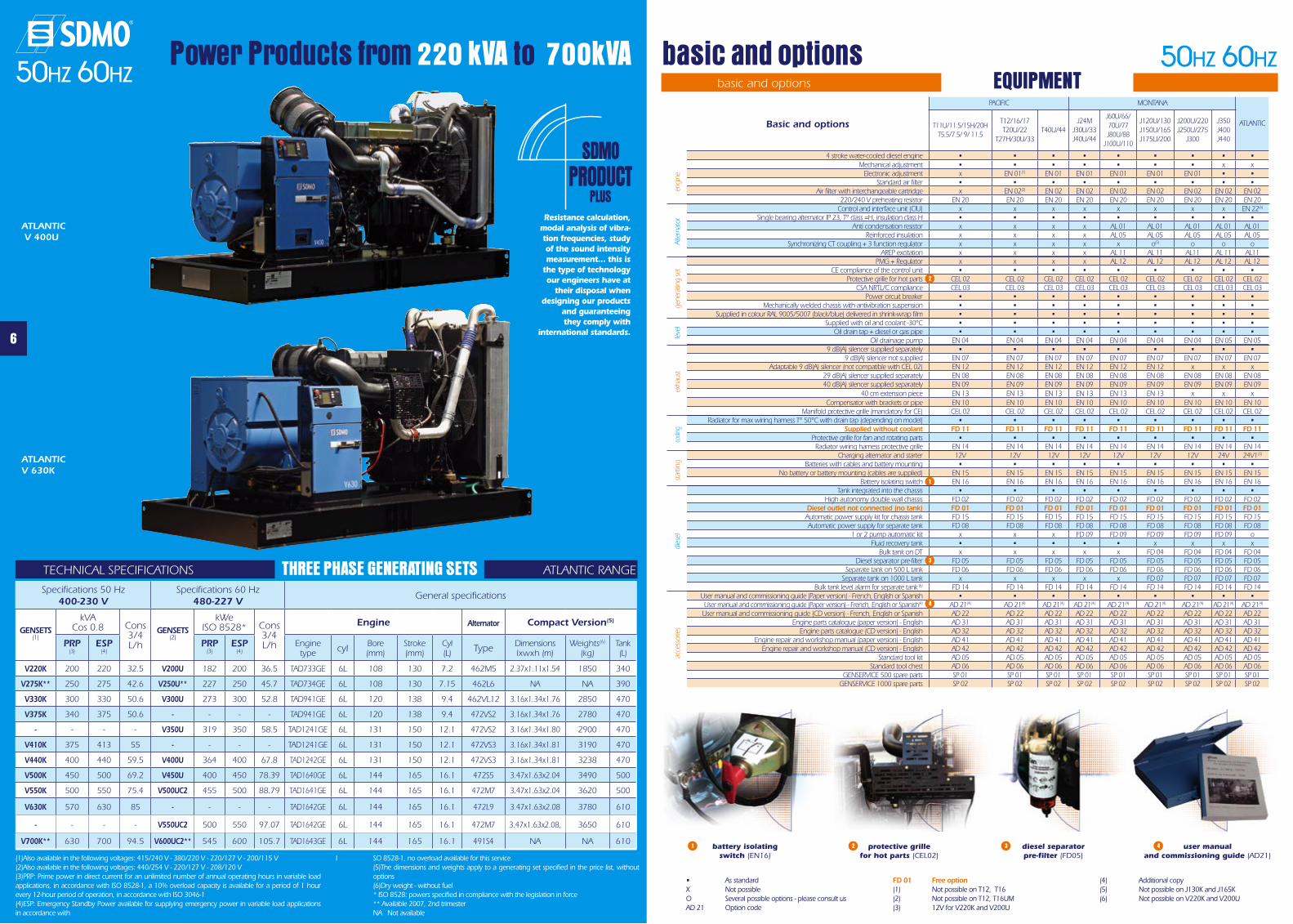
Power Products from 220 kVA to 700kVA
6
basic and options
ATLANTIC V 400U
ATLANTIC V 630K
basic and options EQUIPMENT
• As standardX Not possibleO Several possible options - please consult usAD 21 Option code
FD 01 Free option(1) Not possible on T12, T16(2) Not possible on T12, T16UM(3) 12V for V220K and V200U
(4) Additional copy(5) Not possible on J130K and J165K(6) Not possible on V220K and V200U
engi
neAl
tern
ator
gene
ratin
g se
tle
vel
exha
ust
cooli
ngst
artin
g
battery isolating switch (EN16)
protective grillefor hot parts (CEL02)
diesel separatorpre-filter (FD05)
user manualand commissioning guide (AD21)
1
1
(1)Also available in the following voltages: 415/240 V - 380/220 V - 220/127 V - 200/115 V(2)Also available in the following voltages: 440/254 V - 220/127 V - 208/120 V(3)PRP: Prime power in direct current for an unlimited number of annual operating hours in variable load applications, in accordance with ISO 8528-1, a 10% overload capacity is available for a period of 1 hour every 12-hour period of operation, in accordance with ISO 3046-1(4)ESP: Emergency Standby Power available for supplying emergency power in variable load applications in accordance with
I SO 8528-1, no overload available for this service. (5)The dimensions and weights apply to a generating set specified in the price list, without
options (6)Dry weight - without fuel * ISO 8528: powers specified in compliance with the legislation in force ** Available 2007, 2nd trimester NA Not available
TECHNICAL SPECIFICATIONS ATLANTIC RANGETHREE PHASE GENERATING SETSSpecifications 50 Hz
400-230 VSpecifications 60 Hz
480-227 VGeneral specifications
GENSETS
(1)
kVACos 0.8 Cons
3/4 L/h
GENSETS
(2)
kWeISO 8528* Cons
3/4 L/h
Engine Alternator Compact Version(5)
PRP (3)
ESP(4)
PRP (3)
ESP(4)
Engine type cyl Bore
(mm)Stroke(mm)
Cyl(L) Type Dimensions
lxwxh (m)Weights(6)
(kg)Tank (L)
V220K 200 220 32.5 V200U 182 200 36.5 TAD733GE 6L 108 130 7.2 462M5 2.37x1.11x1.54 1850 340
V275K** 250 275 42.6 V250U** 227 250 45.7 TAD734GE 6L 108 130 7.15 462L6 NA NA 390
V330K 300 330 50.6 V300U 273 300 52.8 TAD941GE 6L 120 138 9.4 462VL12 3.16x1.34x1.76 2850 470
V375K 340 375 50.6 - - - - TAD941GE 6L 120 138 9.4 472VS2 3.16x1.34x1.76 2780 470
- - - - V350U 319 350 58.5 TAD1241GE 6L 131 150 12.1 472VS2 3.16x1.34x1.80 2900 470
V410K 375 413 55 - - - - TAD1241GE 6L 131 150 12.1 472VS3 3.16x1.34x1.81 3190 470
V440K 400 440 59.5 V400U 364 400 67.8 TAD1242GE 6L 131 150 12.1 472VS3 3.16x1.34x1.81 3238 470
V500K 450 500 69.2 V450U 400 450 78.39 TAD1640GE 6L 144 165 16.1 472S5 3.47x1.63x2.04 3490 500
V550K 500 550 75.4 V500UC2 455 500 88.79 TAD1641GE 6L 144 165 16.1 472M7 3.47x1.63x2.04 3620 500
V630K 570 630 85 - - - - TAD1642GE 6L 144 165 16.1 472L9 3.47x1.63x2.08 3780 610
- - - - V550UC2 500 550 97.07 TAD1642GE 6L 144 165 16.1 472M7 3.47x1.63x2.08, 3650 610
V700K** 630 700 94.5 V600UC2** 545 600 105.7 TAD1643GE 6L 144 165 16.1 491S4 NA NA 610
dies
elac
cess
orie
s
2 3 4
3
2
SDMOPRODUCT
PLUSResistance calculation,
modal analysis of vibra-tion frequencies, study of the sound intensity measurement… this is
the type of technology our engineers have at
their disposal when designing our products
and guaranteeing they comply with
international standards.
4
50HZ 60HZ50HZ 60HZ
50HZ 60HZ
8
M128 ENCLOSUREM126 ENCLOSURE
M129 ENCLOSURE
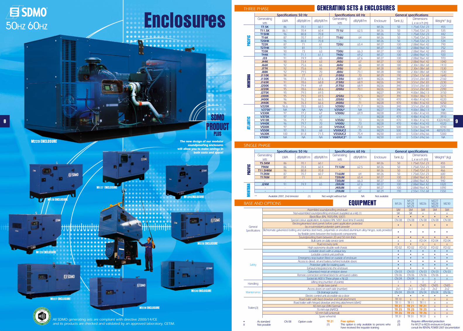
EnclosuresTHREE PHASE
BASE AND OPTIONS
SINGLE PHASE
All SDMO generating sets are compliant with directive 2000/14/CE and its products are checked and validated by an approved laboratory, CETIM.
GENERATING SETS & ENCLOSURES
EQUIPMENT
Specifications 50 Hz Specifications 60 Hz General specificationsGenerating
setsLWA dB(A)@1m dB(A)@7m
Generating sets
dB(A)@7m Enclosure Tank (L)DimensionsL x w x h (m)
Weight(1) (kg)
T7.5K 86 70.1 60.1 - - M126 50 1.75x0.72x1.23 455T11.5K 86.1 70.4 60.4 T11U 62.5 M126 50 1.75x0.72x1.23 535T15HK 96 80.8 70.8 - - M126 50 1.75x0.72x1.23 442T16K 87 70.7 60.7 T16U 64 M126 50 1.75x0.72x1.23 554
T20HK 96 80.8 70.8 - - M126 50 1.75x0.72x1.23 534T22K 87 71 61 T20U 65.4 M127 100 2.08x0.96x1.42 790
T27HK 97 81 71 - - M127 100 2.08x0.96x1.42 752T33K 90 73 63 T30U 66.3 M127 100 2.08x0.96x1.42 890T44K 91 71.1 61.1 T40U 69.2 M127 100 2.08x0.96x1.42 920J33 91 74.9 65 J30U 67.6 M127 100 2.08x0.96x1.42 970
J44K 90 73.4 63 J40U 67 M127 100 2.08x0.96x1.42 1040J66K 92 75.6 66 J60U 66 M128 180 2.30x1.08x1.68 1410J77K 92 75.6 66 J70U 67 M128 180 2.30x1.08x1.68 1530J88K 92 79.5 70 J80U 73.1 M128 180 2.30x1.08x1.68 1530J110K 94 77 67 J100U 70 M129 190 2.55x1.17x1.68 1640J130K 96 77.6 67.6 J120U 68.9 M226 340 3.51x1.20x1.83 2160J165K 91 78.6 68.8 J150U 68.9 M226 340 3.51x1.20x1.83 2230J200K 95 79.4 69 J175U 68.9 M226 340 3.51x1.20x1.83 2320J220K 95 78.6 68.6 J200U 70.1 M226 340 3.51x1.20x1.83 2390J275K 95 79.5 69.5 - - M227 390 4.00x1.38x2.13 3150J300K 95 79.5 69.5 J250U 72.5 M227 390 4.00x1.38x2.13 3215J400K 96 76.2 66.5 J350U 71 M228 470 4.48x1.41x2.43 4220J440K 96 76.3 66.6 J400U 71 M228 470 4.48x1.41x2.43 4250V220K 96.6 78.5 68.5 V200U 71.7 M226 340 3.51x1.20x1.83 2490
V275K* NA NA NA V250U* NA M227 390 4.00x1.38x2.13 NAV330K 97 77.2 67 V300U 69.9 M228 470 4.48x1.41x2.43 3980V375K 97 77.2 67 - - M228 470 4.48x1.41x2.43 3910V410K 96 79.7 70 V350U 73 M228 470 4.48x1.41x2.43 4320/4020V440K 96 79.7 70 V400U 73 M228 470 4.48x1.41x2.43 4320V500K 97 77.6 68 V450UC 73.8 M229 500 5.03x1.56x2.44 4740V550K 97 78.1 68 V500UC2 75 M229 500 5.03x1.56x2.44 4870/5170V630K 100 81.8 71.5 V550UC2 75.4 M230 610 5.03x1.69x2.66 5300V700K* NA NA NA V600UC2* NA M230 610 5.03x1.69x2.66 NA
PACI
FIC
MON
TANA
ATLA
NTIC
Specifications 50 Hz Specifications 60 Hz General specificationsGenerating
setsLWA dB(A)@1m dB(A)@7m
Generating sets
dB(A)@7m Enclosure Tank (L)DimensionsL x w x h (m)
Weight(1) (kg)
T5.5KM 86 70.1 60.1 - - M126 50 1.75x0.72x1.23 455T9KM 86 70.4 60.4 T11UM 62.5 M126 50 1.75x0.72x1.23 544
T11.5HKM 96 80.8 70.8 - - M126 50 1.75x0.72x1.23 466T12KM 87 70.7 60.7 T16UM 64 M126 50 1.75x0.72x1.23 600T17KM 87 71 61 T20UM 65.4 M127 100 2.08x0.96x1.42 810
- - - - T30UM 66.3 M127 100 2.08x0.96x1.42 940 J24M 91 74.9 65 J30UM 67.6 M127 100 2.08x0.96x1.42 1020
- - - - J40UM 67 M127 100 2.08x0.96x1.42 1090 - - - - J70UM 67 M129 190 2.55x1.17x1.68 1550
PACI
FIC
MON
TANA
M126M127M128M129
M226M227M228M229
M230
General Specifications
Assembled soundproofing enclosure SiM SiM SiM SiM SiMNon-assembled soundproofing enclosure (supplied as a kit) (1) SiK SiK x x x
Black/Blue (RAL 9005/RAL 5007) • • • • •Special colour application, to replace RAL 5007 (lead time 8 weeks) CN 08 CN 08 CN 08 CN 08 CN 08Electrogalvanised steel panels before paint application protected
by a rust-resistant polyester paint powder • • • • •
Bichromate galvanized bolting and stainless steel rivets, polyamide or anodised aluminium alloy hinges, seals provided by flexible joints between the bodywork components
• • • • •
Soundproofing foam between 20 and 50 mm thick • • • • •Bulk tank on daily service tank x x FD 04 FD 04 FD 04
Fluid recovery tank • • x x xHigh autonomy double wall chassis FD 02 FD 02 FD 02 FD 02 FD 02
Safety
Lockable doors with a unique key • • • • •Lockable control unit porthole • • • • •
Emergency stop button fitted on outside of enclosure • • • • •Access to diesel, oil and battery behind lockable doors • • • • •
Protective grille for rotating parts • • • • •Exhaust integrated into the enclosure • • • • •Galvanised metal air emission sleeve CN 03 CN 03 CN 03 CN 03 CN 03
Remote connection terminal block for armoured cables CN 06 CN 06 CN 06 CN 06 xSocket kit (400 V Three phase + N) (2) CN 04 CN 04 x x x
Handling Lifting ring (number of points) 1 1 1 2Single base panel x x CN05 CN05 CN05
MaintenanceAccess doors on each side (number) 2+1 2+1 2+2 2+2 2+2
Oil drainage pump EN 04 EN 04 EN 04 EN 04 EN 06Electric control unit accessible via a door • • • • •
Trailers(3)
Road trailer with fixed drawbar and ball attachment TR 10 x x x xRoad trailer with hinged drawbar and ring attachment 68x42 TR 11 TR 11 TR 11 x x
40 mm eye (DIN German) TR 21 TR 21 TR 21 x x76 mm eye (NATO) TR 25 TR 25 TR 25 x x
50 mm ball (universal) TR 26 TR 26 TR 26 x xSpare wheel kit TR 31 TR 31 TR 31 x x
• As standardX Not possible
CN 08 Option code
M229 ENCLOSURE
M127 ENCLOSURE
M226 ENCLOSURE
M227 ENCLOSURE
SDMOPRODUCT
PLUSThe new design of our modular
soundproofing enclosures will allow you to make savings in
both costs and space!
9
TR 21 Free option(1) This option is only available to persons who
have received the requisite training
(2) Requires differential protection(3) For M127 to M226 enclosures in Europe, consult the RENTAL POWER 2007 documentation
M228 ENCLOSURE
M230 ENCLOSURE
** Available 2007, 2nd trimester (1) Net weight without fuel NA Not available
10
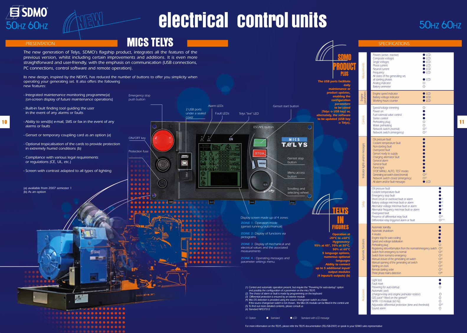
electrical control units The new generation of Telys, SDMO's flagship product, integrates all the features of the previous version, whilst including certain improvements and additions. It is even more straightforward and user-friendly, with the emphasis on communication (USB connections, PC connections, control software and remote operation).
Its new design, inspired by the NEXYS, has reduced the number of buttons to offer you simplicity when operating your generating set. It also offers the following new features:
- Integrated maintenance monitoring programme(a) (on-screen display of future maintenance operations)
- Built-in fault finding tool guiding the user in the event of any alarms or faults
- Ability to send(b) e-mail, SMS or fax in the event of any alarms or faults
- Genset or temporary coupling card as an option (a)
- Optional tropicalisation of the cards to provide protection in extremely humid conditions (b)
- Compliance with various legal requirements or regulations (CE, UL, etc.)
- Screen with contrast adapted to all types of lighting
(a) available from 2007 semester 1(b) As an option
PRESENTATION MICS TELYSSDMO
PRODUCTPLUS
The USB ports facilitate daily
maintenance or product updates,
enabling the configuration
parameters to be saved
(Telys -> USB key) or, alternately, the software to be updated (USB key
-> Telys).
Alarm LEDs
Fault LEDs Telys "live" LED
Genset start button
Genset stop button
Menu access button
ESCAPE button
Scrolling and selecting wheel
ZONE 1: Operation mode (genset running/auto/manual)
ZONE 2: Display of functions via pictograms
ZONE 3: Display of mechanical and electrical values and the associated measurements
ZONE 4 : Operating messages and parameter settings menu
Display screen made up of 4 zones:
Protection fuse
ON/OFF key
Emergency stop push button
2 USB ports under a sealed cover
11
O Option ● Standard ● LCD Standard with LCD message
(1) Control and automatic operation present, but require the "Prewiring for auto-startup" option and possibly the configuration of a parameter on the mics TELYS
(2) The choice of alarm or fault is made by programming on the keyboard (3) Differential protection is ensured by an exterior module(4) Mics DS detection is provided using the source changeover switch as a base.
If the source changeover switch is not chosen, the Mics DS module can be fitted in the control unit(5) To find out more detailed contents, please consult us(6) Standard NFE37312
50HZ 60HZ 50HZ 60HZ
For more information on the TELYS, please refer the TELYS documentation (TEL/GB-2007) or speak to your SDMO sales representative
TELYSIN
FIGURESOperation at
-20°C to +60°CHygrometry:
95% at 45°, 70% at 50°C, 50% at 60°C
5 language options, numerous optional
languagesAbility to connect
up to 5 additional input/ output modules
(4 inputs/6 outputs) (b)
SPECIFICATIONS
Safe
tyAu
tom
atic
func
tions
Acce
ssor
ies
Oil pressure fault ● Coolant temperature fault ● Emergency stop fault ● Short circuit or overload fault or alarm ●(2)
Battery voltage min/max fault or alarm ●(2)
Alternator voltage min/max fault or alarm ●(2)
Alternator frequency min/max fault or alarm ●(2)
Overspeed fault ● Presence of differential relay fault O(3)
Differential relay triggered alarm or fault O(2=3)
Automatic standby ● Automatic shutdown ● 4 modes ● Engine stop for auto cooling ● Speed and voltage stabilisation ● Preheating plug O Registering retro-information from the normal/emergency switch O(1)
Switch from emergency to normal O(1)
Switch from normal to emergency O(1)
Manual closure of the generating set switch O(1)
Manual opening of the generating set switch O(1)
Starting on clock O(1)
Remote starting order O(1)
Three phase mains detection O(4)
Light test ● Fault reset ● Prewiring for auto-startup O Automatic pack (charger+relay and engine preheater resistor) O GES pack(5) fitted on the genset(6) O NFPA 110 module (60 Hz) O Adjustable differential protection (time and threshold) O(2)
Sound alarm O
Engi
ne
para
met
ers
Mea
sure
men
tsIn
dica
tor l
ight
s and
/or m
essa
ges
Powers (active, reactive) ● LCD Composite voltages ● LCD Single voltages ● LCD Phase current ● LCD Neutral current ● LCD Frequency ● LCD All states of the generating set, all starting phases ● LCD Analog indicator O Battery ammeter O Engine speed indicator ● LCD Battery voltage indicator ● LCD Working hours counter ● LCD Speed/voltage trimming O Power on ● Fuel solenoid valve control ● Starter control ● Preheating plug O Water preheating O Network switch (normal) O(1) Network switch (emergency) O(1)
Oil pressure fault ● Coolant temperature fault ● Non-starting fault ● Overspeed fault ● Genset ready to supply ● Charging alternator fault ● General alarm ● General fault ● Panel light ● STOP, MANU, AUTO, TEST modes ● Generating set switch closed (normal) O(1)
Network switch closed (emergency) O(1)
All alarm and/or fault messages ● LCD
Cont
rols
12
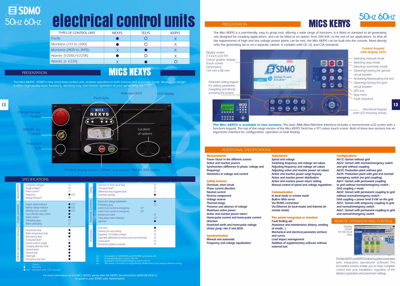
The Mics KERYS is a user-friendly, easy to grasp tool, offering a wide range of functions. It is fitted as standard to all generating sets designed for coupling applications, and can be fitted as an option, from 200 kVA, to the rest of our applications. So that all the requirements of high and low voltage power plants can be met, the Mics KERYS can be built into the console, fitted directly onto the generating set or on a separate cabinet. It complies with CE, UL and CSA standards.
Display screen7.4 inch LCD TFTColour graphic displayTouch screenDimensions: 154 mm x 86 mm
The Mics KERYS is available in two versions. The basic MMI (Man/Machine Interface) includes a monochrome LCD screen with a functions keypad. The top of the range version of the Mics KERYS Tactil has a TFT colour touch screen. Both of these two versions has an ergonomic interface for configuration, operation or fault finding.
* For more information, please refer to the Mics KERYS documentation or speak to your SDMO sales representative.
PRESENTATION MICS KERYS
ADDITIONAL SPECIFICATIONS
Control keypadwith display LEDs
Selecting manual modeSelecting stop modeSelecting automatic modeOpening/closing the genset circuit breakerActivating/deactivating the testOpening/closing the grid circuit breakerLED testStop hornFault clearance
Directional keypadwith LED showing activity
Parameter setting keypadFor setting parameters, navigating and directly accessing the screens
MeasurementsPower factor in the different screensActive and reactive powersSynchronism (difference in phase, voltage and frequency)Harmonics in voltage and current
Safety featuresOverload, short circuitPhase current directionNeutral currentReverse componentVoltage reserveThermal imagePresence and absence of voltageMaximum active powerActive and reactive power returnHomo-polar current and homo-polar current directionRestricted earth and homo-polar voltageVector jump, min Z and df/dt
SynchronisationManual and automaticFrequency and voltage equalisation
AdjustmentSpeed and voltageSwitching frequency and voltage set valuesAdjusting frequency and voltage set valuesAdjusting active and reactive power set valuesActive and reactive power surge keywayActive and reactive power distributionActive and reactive power return settingManual control of speed and voltage regulations
CommunicationIn local mode or remote modeBuilt-in Web serverVia RS485 connectionVia Ethernet (in local mode) and Internet (in remote mode)
Plus points integrated as standardFault finding aidAssistance and maintenance (history, sending of emails...)Mechanical and electrical parameter archives and curvesLoad impact managementAddition of supplementary software without external tool
ConfigurationsA612: Genset without gridA622: Genset with normal/emergency switch and grid without couplingA633: Production plant without gridA634: Production plant with grid and normal/emergency switch (no grid coupling)A641: Genset with permanent coupling to grid without normal/emergency switch - Grid coupling + resaleA642: Genset with permanent coupling to grid without normal/emergency switch - Grid coupling + power level 0 kW on the gridA651: Genset with temporary coupling to grid and normal/emergency switchA661: Genset with permanent coupling to grid and normal/emergency switch
The Mics KERYS and KERYS Tactil are supplied as standard with integrated operational software. The 60 resident screens enable you to have complete control over your installation, regardless of the distance (operation and parameter setting).
Display screen
for electrical data
REMOTE OPERATION AND CONTROL
13
electrical control units En
gine
par
amet
ers
The Mics NEXYS, SDMO's new entry-level control unit, enables operation in both manual and automatic mode. Modular in design, it offers high-quality basic functions, allowing easy and reliable operation of your generating set.
Emergency stop button
ON/OFF key switch
Protection fuse
O Option ● Standard ● LCD Standard with LCD message
Scrolling display button / Genset stop button / Genset start button
LCD displayIndicator LEDS
Panel light
Location of options
For more information on the MICS NEXYS, please refer the NEXYS documentation (NEX/GB-2006/1) or speak to your SDMO sales representative
PRESENTATION MICS NEXYS
SPECIFICATIONS
Mea
sure
men
tsIn
dica
tor l
ight
s and
/or m
essa
ges
Composite voltages(1) O Single voltages(1) O Phase current(1) O Frequency ● LCD Analog indicator(1) O Engine speed indicator ● LCD Battery voltage indicator ● LCD Working hours counter ● LCD Fuel solenoid valve control ● Starter control ● Preheating plug O Water preheating O Oil pressure fault ● Water temperature fault ● Non-starting fault ● Overspeed fault(1) O Genset ready to supply ● Charging alternator fault ● General alarm ● General fault ● Panel light ● Emergency stop fault ●
Safe
tyAu
tom
atic
func
tions
Acce
ssor
ies
Overload or short circuit fault O Overspeed fault(1) O Differential relay triggered fault O Automatic standby ●
Speed and voltage stabilisation ●
Preheating plug O Switch from normal to emergency O(2)
Switch from normal to emergency O(2)
Remote start order O Three phase mains detection O(3)
Light test ●
Fault reset ●
Prewiring for auto-startup O Regulated 12V battery charger O Adjustable differential protection (time and threshold) O Sound alarm O Permanent isolation controller O
(1) As standard on MONTANA and ATLANTIC generating sets (2) If normal/emergency switch with TSI (3) Standard in the normal/emergency switch with TSI (4) The choice is reviewed via programming. Modification of the voltage reference wiring
50HZ 60HZ50HZ 60HZ
TYPES OF CONTROL UNIT NEXYS TELYS KERYS
Pacific
Montana (J33 to J300)
Montana (J400 to J440)
Atlantic (V200U-V220K)
Atlantic (> V220)
X
X
XX
X
X
14
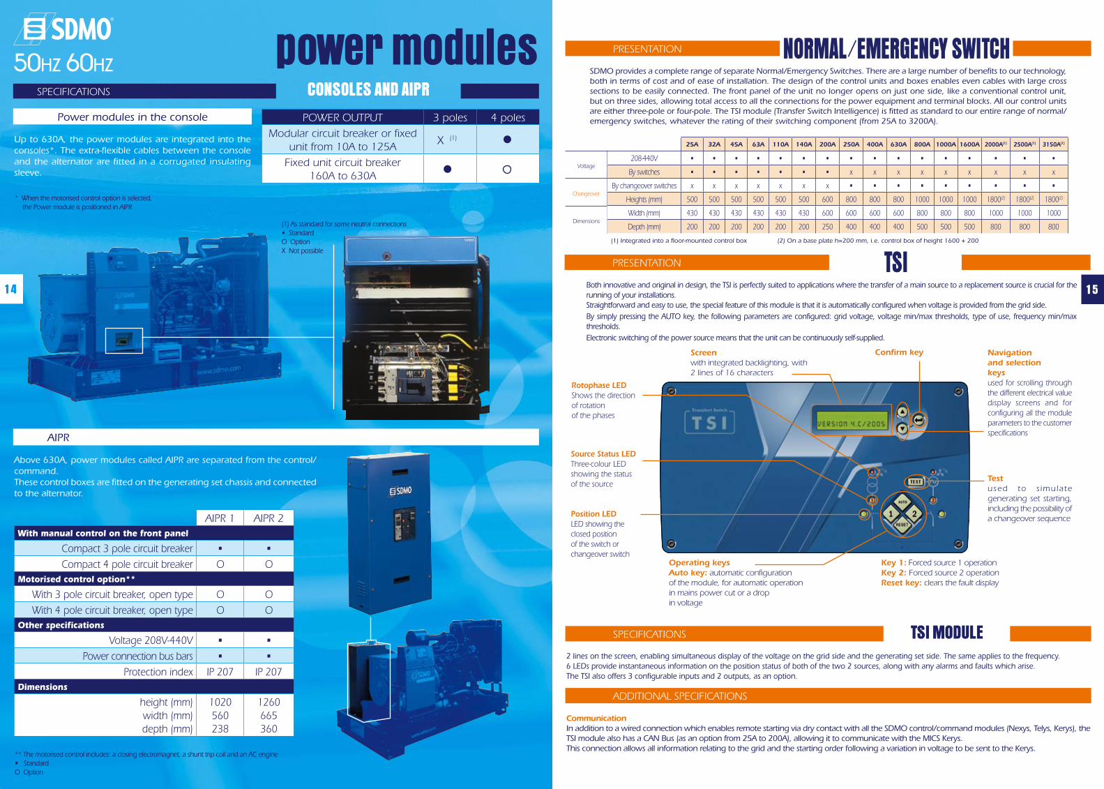
SDMO provides a complete range of separate Normal/Emergency Switches. There are a large number of benefits to our technology, both in terms of cost and of ease of installation. The design of the control units and boxes enables even cables with large cross sections to be easily connected. The front panel of the unit no longer opens on just one side, like a conventional control unit, but on three sides, allowing total access to all the connections for the power equipment and terminal blocks. All our control units are either three-pole or four-pole. The TSI module (Transfer Switch Intelligence) is fitted as standard to our entire range of normal/emergency switches, whatever the rating of their switching component (from 25A to 3200A).
PRESENTATION
25A 32A 45A 63A 110A 140A 200A 250A 400A 630A 800A 1000A 1600A 2000A(1) 2500A(1) 3150A(1)
208-440V • • • • • • • • • • • • • • • •
By switches • • • • • • • x x x x x x x x x
By changeover switches x x x x x x x • • • • • • • • •
Heights (mm) 500 500 500 500 500 500 600 800 800 800 1000 1000 1000 1800(2) 1800(2) 1800(2)
Width (mm) 430 430 430 430 430 430 600 600 600 600 800 800 800 1000 1000 1000
Depth (mm) 200 200 200 200 200 200 250 400 400 400 500 500 500 800 800 800
Voltage
Changeover
Dimensions
(1) Integrated into a floor-mounted control box (2) On a base plate h=200 mm, i.e. control box of height 1600 + 200
Both innovative and original in design, the TSI is perfectly suited to applications where the transfer of a main source to a replacement source is crucial for the running of your installations.Straightforward and easy to use, the special feature of this module is that it is automatically configured when voltage is provided from the grid side. By simply pressing the AUTO key, the following parameters are configured: grid voltage, voltage min/max thresholds, type of use, frequency min/max thresholds.Electronic switching of the power source means that the unit can be continuously self-supplied.
PRESENTATION TSI
Rotophase LED Shows the direction of rotation of the phases
Source Status LED Three-colour LED showing the status of the source
Position LEDLED showing the closed position of the switch or changeover switch
Screen with integrated backlighting, with 2 lines of 16 characters
Confirm key Navigationand selection keysused for scrolling through the different electrical value display screens and for configuring all the module parameters to the customer specifications
Testused to s imulate generating set starting, including the possibility of a changeover sequence
Operating keysAuto key: automatic configurationof the module, for automatic operationin mains power cut or a drop in voltage
Key 1: Forced source 1 operationKey 2: Forced source 2 operationReset key: clears the fault display
2 lines on the screen, enabling simultaneous display of the voltage on the grid side and the generating set side. The same applies to the frequency.6 LEDs provide instantaneous information on the position status of both of the two 2 sources, along with any alarms and faults which arise.The TSI also offers 3 configurable inputs and 2 outputs, as an option.
15
SPECIFICATIONS TSI MODULE
ADDITIONAL SPECIFICATIONS
CommunicationIn addition to a wired connection which enables remote starting via dry contact with all the SDMO control/command modules (Nexys, Telys, Kerys), the TSI module also has a CAN Bus (as an option from 25A to 200A), allowing it to communicate with the MICS Kerys.This connection allows all information relating to the grid and the starting order following a variation in voltage to be sent to the Kerys.
SPECIFICATIONS CONSOLES AND AIPR
Up to 630A, the power modules are integrated into the consoles*. The extra-flexible cables between the console and the alternator are fitted in a corrugated insulating sleeve.
Power modules in the console
(1) As standard for some neutral connections• Standard O Option X Not possible
POWER OUTPUT 3 poles 4 poles
Modular circuit breaker or fixed unit from 10A to 125A
(1)
Fixed unit circuit breaker 160A to 630A
Above 630A, power modules called AIPR are separated from the control/command. These control boxes are fitted on the generating set chassis and connected to the alternator.
AIPR
** The motorised control includes: a closing electromagnet, a shunt trip coil and an AC engine• Standard O Option
AIPR 1 AIPR 2With manual control on the front panel
Compact 3 pole circuit breaker • •
Compact 4 pole circuit breaker O OMotorised control option**
With 3 pole circuit breaker, open type O O
With 4 pole circuit breaker, open type O OOther specifications
Voltage 208V-440V • •
Power connection bus bars • •
Protection index IP 207 IP 207Dimensions
height (mm)width (mm)depth (mm)
1020560238
1260665360
power modules50HZ 60HZ
* When the motorised control option is selected, the Power module is positioned in AIPR
X
NORMAL/EMERGENCY SWITCH