POWER (power optimization for wireless energy requirements ...
23
Journal of Power Sources xxx (2005) xxx–xxx POWER (power optimization for wireless energy requirements): A MATLAB based algorithm for design of hybrid energy systems K.A. Cook a , F. Albano b , P.E. Nevius c , A.M. Sastry a,b,c,∗ a Department of Biomedical Engineering, University of Michigan, Ann Arbor, MI 48105, USA b Department of Material Science Engineering, University of Michigan, Ann Arbor, MI 48105, USA c Department of Mechanical Engineering, University of Michigan, Ann Arbor, MI 48105, USA Received 12 July 2005; received in revised form 12 October 2005; accepted 17 October 2005 Abstract We have expanded and implemented an algorithm for selecting power supplies into a turnkey MATLAB code, “POWER” (power optimization for wireless energy requirements). Our algorithm uses three approaches to system design, specifying either: (1) a single, aggregate power profile; (2) a power system designed to satisfy several power ranges (micro-, milli- and Watt); or (3) a power system designed to be housed within specified spaces within the system. POWER was verified by conducting two case studies on hearing prosthetics: the TICA (LZ 3001) (Baumann group at the T¨ ubingen University) and Amadeus cochlear implant (CI) (WIMS-ERC at the University of Michigan) based on a volume constraint of 2 cm 3 . The most suitable solution identified by POWER for the TICA device came from Approach 1, wherein one secondary cell provided 26,000 cycles of 16 h operation. POWER identified Approach 2 as the solution for the WIMS-ERC Amadeus CI, which consisted of 1 cell for the microWatt power range and 1 cell for the milliWatt range (4.43 cm 3 , ∼55% higher than the target volume), and provided 3280 cycles of 16 h operation (including re-charge of the batteries). Future work will be focused on continuously improving our present tool. © 2005 Elsevier B.V. All rights reserved. Keywords: MEMS; Batteries; Hybrid; Algorithm; Cochlear; Implant 1. Introduction Recently, we introduced an algorithm [1] to design hybrid battery systems for multi-component, wireless microelectron- ics. Proof of concept was established using the Wireless Inte- grated Microsystems Engineering Research Center (WIMS- ERC) Environmental Monitor Testbed (EMT) at the University of Michigan. Use of our algorithm resulted in significant reduc- tion in both mass and volume of power supplies, over trial-and- error selection of batteries. For the WIMS-ERC EMT testbed, we designed a power supply weighing 32 mg, comprised of thin- film lithium-free [2] and prismatic lithium polymer secondary cells; these were, respectively, the Ultralife UBC422030/PCM and UBC641730/PCM [3]. Our methodology [1] constrained operating temperature, energy/power density, and specific energy/power; we further ∗ Corresponding author. E-mail address: [email protected] (A.M. Sastry). allowed requirements/constraints on rechargeability, mass, vol- ume, and lifetime in selection of appropriate battery electro- chemistries and configurations (i.e. parallel, series, or combi- nations thereof). Our algorithm separately evaluated results of three approaches to system design, specifying either: (1) a single, aggregate power profile; (2) a power system designed to satisfy several power ranges (micro-, milli- and Watt); or (3) a power system designed to be housed within specified spaces within the system, with device constraints on volume and surface area. In this paper, we describe the expansion and implementation of our algorithm into a turnkey MATLAB [4] code. We set out the following objectives in this work, to expand our original algorithm to its present realization: (1) to implement simple models to account for capacity fade as a function of discharge current and cycling, using our own, and manufacturer-generated data on primary coin cells; (2) to implement an algorithm for binning device voltage and current requirements within the micro-, milli- and Watt power ranges, along with expressions for calculating tar- 0378-7753/$ – see front matter © 2005 Elsevier B.V. All rights reserved. doi:10.1016/j.jpowsour.2005.10.062 POWER-7497; No. of Pages 23
Transcript of POWER (power optimization for wireless energy requirements ...

Journal of Power Sources xxx (2005) xxx–xxx
POWER (power optimization for wireless energy requirements): AMATLAB based algorithm for design of hybrid energy systems
K.A. Cooka, F. Albanob, P.E. Neviusc, A.M. Sastrya,b,c,∗a Department of Biomedical Engineering, University of Michigan, Ann Arbor, MI 48105, USA
b Department of Material Science Engineering, University of Michigan, Ann Arbor, MI 48105, USAc Department of Mechanical Engineering, University of Michigan, Ann Arbor, MI 48105, USA
Received 12 July 2005; received in revised form 12 October 2005; accepted 17 October 2005
Abstract
We have expanded and implemented an algorithm for selecting power supplies into a turnkey MATLAB code, “POWER” (power optimizationfor wireless energy requirements). Our algorithm uses three approaches to system design, specifying either: (1) a single, aggregate power profile;(2) a power system designed to satisfy several power ranges (micro-, milli- and Watt); or (3) a power system designed to be housed within specifieds group at theT cmm cycles of1 att powerr ludingr©
K
1
bigEotewfica
e
, vol-tro-mbi-lts ofingle,atisfywerin thea.ationt
nal
e aswn,s;andatttar-
0d
paces within the system. POWER was verified by conducting two case studies on hearing prosthetics: the TICA (LZ 3001) (Baumannubingen University) and Amadeus cochlear implant (CI) (WIMS-ERC at the University of Michigan) based on a volume constraint of 23. Theost suitable solution identified by POWER for the TICA device came from Approach 1, wherein one secondary cell provided 26,0006 h operation. POWER identified Approach 2 as the solution for the WIMS-ERC Amadeus CI, which consisted of 1 cell for the microWange and 1 cell for the milliWatt range (4.43 cm3, ∼55% higher than the target volume), and provided 3280 cycles of 16 h operation (ince-charge of the batteries). Future work will be focused on continuously improving our present tool.
2005 Elsevier B.V. All rights reserved.
eywords: MEMS; Batteries; Hybrid; Algorithm; Cochlear; Implant
. Introduction
Recently, we introduced an algorithm[1] to design hybridattery systems for multi-component, wireless microelectron-
cs. Proof of concept was established using the Wireless Inte-rated Microsystems Engineering Research Center (WIMS-RC) Environmental Monitor Testbed (EMT) at the Universityf Michigan. Use of our algorithm resulted in significant reduc-
ion in both mass and volume of power supplies, over trial-and-rror selection of batteries. For the WIMS-ERC EMT testbed,e designed a power supply weighing 32 mg, comprised of thin-lm lithium-free [2] and prismatic lithium polymer secondaryells; these were, respectively, the Ultralife UBC422030/PCMnd UBC641730/PCM[3].
Our methodology[1] constrained operating temperature,nergy/power density, and specific energy/power; we further
∗ Corresponding author.E-mail address: [email protected] (A.M. Sastry).
allowed requirements/constraints on rechargeability, massume, and lifetime in selection of appropriate battery elecchemistries and configurations (i.e. parallel, series, or conations thereof). Our algorithm separately evaluated resuthree approaches to system design, specifying either: (1) a saggregate power profile; (2) a power system designed to sseveral power ranges (micro-, milli- and Watt); or (3) a posystem designed to be housed within specified spaces withsystem, with device constraints on volume and surface are
In this paper, we describe the expansion and implementof our algorithm into a turnkey MATLAB[4] code. We set outhe following objectives in this work, to expand our origialgorithm to its present realization:
(1) to implement simple models to account for capacity fada function of discharge current and cycling, using our oand manufacturer-generated data on primary coin cell
(2) to implement an algorithm for binning device voltagecurrent requirements within the micro-, milli- and Wpower ranges, along with expressions for calculating
378-7753/$ – see front matter © 2005 Elsevier B.V. All rights reserved.oi:10.1016/j.jpowsour.2005.10.062
POWER-7497; No. of Pages 23
2 K.A. Cook et al. / Journal of Power Sources xxx (2005) xxx–xxx
Nomenclature
Alphabeta number of cell configurations (integer number)b voltage (V)c cycle (integer number)e energy (Wh)I current (A)L lifetime (cycles)M mass (kg)N number of cells (integer number)P percent capacity fade (normalized number in the
interval [0,1])p power (W)t time (s)V volume (L)w weighted power (W)X total capacity (Ah)
Greek symbolsχ capacity (Ah) at a given time increment
Superscripts and subscriptsc cyclectr counterctr com counteri indexloc power sitep primaryr rth cells secondarysys systemtotal summation∼ specific property (kg−1)ˆ density (L−1)
get micro-, milli- and Watt mass, volume and area targetvalues, based on user-defined battery numbers;
(3) to implement criteria in the algorithm to limit voltage andcurrent of power sites; and finally,
(4) to implement a discretization scheme for user-input currenprofiles.
This new code, “POWER” (power optimization for wire-less energy requirements), employs a graphical user interfac(GUI) to allow step-by-step input of system data by the user.To verify our implementation, we conducted two case stud-ies in power selection. The first was a re-examination of workdone at Tubingen University[5–8] in a fully implantable hear-ing prosthesis designed to mechanically stimulate the tympanimembrane, the Totally Implantable Communication Assistance(TICA) [5–8]. The second case study comprised design of apower system for a novel cochlear implant, the Amadeus, developed at the University of Michigan’s WIMS-ERC[9–11].
2. Background
2.1. Cell capacity
Theoretical cell capacity is determined as the ratio of the sumof the electrochemical equivalent of the active materials, andthe total number of electrons involved in the reaction. Capacityfade, i.e. loss of discharge capacity when the battery is inactive(“calendar life” loss) or in use (“cycle life” loss), can sub-stantially reduce performance[12]. This phenomenon has beenextensively studied in primary and secondary lithium-silver-vanadium-oxide, lithium-manganese dioxide, lithium-thionyl,zinc-silver oxide; and lithium, lithium-ion, lithium polymer,and zinc silver nickel metal hydride cells, respectively, by thebiomedical device[13–15], defense[16], computer[17], hybridand electrical vehicle[18,19], and cellular phone[20] indus-tries. It can be reversible, in which case it is commonly referredto as self-discharge. Industrially, battery capacity lost in an open-circuit, i.e. where no load is attached to the battery, is also calledlocal action[12,21–23].
Capacity fade is more pronounced at high rates of discharge[24–27], and is further affected by depth of discharge (DOD)[28,29], number of cycles[30–32], materials used (e.g. chemi-cally co-precipitated calcium zincate as an active material in zincelectrodes[33] and Si3-xFexN4 compound as a possible anodefor rechargeable lithium batteries[34]), and/or use of additives( sm nics r-aa eries[ s ono ium-i -a
2c
spe-coi n-sf si-c ERd owerr
TC ndaryc
LMH
t
e
c
-
e.g. metallic bismuth in zinc electrodes[33], and amorphouanganese oxides[35] and ketjen black dispersed in orga
olvents used in lithium-ion cells[36]). High operating tempetures (e.g. for lithium and lithium-ion cells[12,17,30,37,38])nd high storage temperatures (e.g. for lithium-ion batt
29,38,39]) can also exacerbate capacity fade. Restrictionperating and storage temperatures have limited use of lith
on cells in self-heating portable electronics[17], under moderte and high discharge currents.
.2. Specific energy/power, power/energy density and rateharacterization
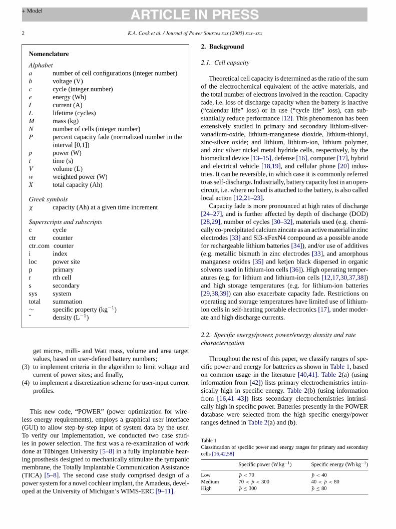
Throughout the rest of this paper, we classify ranges ofific power and energy for batteries as shown inTable 1, basedn common usage in the literature[40,41]. Table 2(a) (using
nformation from[42]) lists primary electrochemistries intriically high in specific energy.Table 2(b) (using informationrom [16,41–43]) lists secondary electrochemistries intrinally high in specific power. Batteries presently in the POWatabase were selected from the high specific energy/panges defined inTable 2(a) and (b).
able 1lassification of specific power and energy ranges for primary and secoells[16,42,58]
Specific power (W kg−1) Specific energy (Wh kg−1)
ow p < 70 p < 40edium 70< p < 300 40< p < 80igh p ≤ 300 p ≤ 80

K.A. Cook et al. / Journal of Power Sources xxx (2005) xxx–xxx 3
Table 2Primary and secondary electrochemistries intrinsically high in specific energy
Anode Cathode Electrolyte Nominalvoltage (V)
Cell type Specific energy(Wh kg−1)
Energy density(Wh L−1)
Specific power(W kg−1)
Operatingtemperature (◦C)
(a) Primary cellsHigh specific energy and medium specific power
Li So2 Organic solvent 3.0 Cylindrical 260 415 90 −55–70Li MnO2 Organic solvent 3.0 Button 230 545 65 −20–55
High specific energy and low specific powerZn O2 (air) KOH (aqueous) 1.5 Prismatic 370 1300 8 0–50Zn O2 (air) KOH (aqueous) 1.5 Cylindrical 300 800 8 0–50Zn MnO2 KOH (aqueous) 1.5 Cylindrical 100 195 50 −60–85Zn HgO KOH or NaOH
(aqueous)1.35 Button 100 470 10.5 0–55
(b) Secondary cellsHigh specific power and low/medium specific energy
Pb PbO2 H2SO4 (aqueous) 2.0 SLI (starting lighting andignition) prismatic
35 70 1600 (10 s) to800 kW(0.1 s)5
−40–55
MH NiOOH KOH (aqueous) 1.2 Button, cylindrical, andprismatic
75 240 2000–22002 −20–50
Zn NiOOH KOH (aqueous) 1.65 Cylindrical, prismaticsealed and vented
50–60 80–120 300 −10–50
High specific power and high specific energyZn MnO2 KOH (aqueous) 1.5 Cylindrical 85 250 150 −20–40C LiCoO2 Organic solvent 4.0 Cylindrical and prismatic 150 400 6503 −20–50Zn AgO KOH (aqueous) 1.5 Prismatic 105 180 6004 −20–60
Data taken from[16,42,58].
2.3. Strategies employed previously, and present approach
Most power supplies for microelectronic devices are pre-scribed after design is nearly complete. Power supplies are thusfrequently an afterthought: of the microelectronic devices listedin Table 3 [44–49]only one was operated and tested with abattery[45]. All others used external power supplies.
The devices inTable 3 require power in the milliWattrange (0.3–25 mW) and voltages >3.3 V. Indeed, though notevenly-spaced in terms of order-of-magnitude, the ranges ofmicro-, milli- and Watt power arise commonly in wirelesselectronics due to the intrinsic demands of their subcompo-nents. Dynamic power switching, ubiquitous in wireless devices,requires power in the milliWatt range[1], and is requiredfor device activation, volume fluctuation, wireless data trans-mittal/reception, computation, heating/cooling, actuation, andalarms (Tables 3 and 4). Innovations in the field have resultedin reductions in supply voltage and increases switching fre-quency [50–52], which in turn have resulted in reductionsin milli- and Watt power range consumption. In the milli-Watt range, for example, improvements in adiabatic differentialswitch logic and gate resizing for very large scale integrated(VSLI) circuits have reduced power demands by 26% and2.8–27.9%, respectively[50,53,54]. In the Watt range, improve-ment of parallel Huffman decoders, and improvements in firstlevel filtering caches used for modem microprocessors haverI ntlyc cloc
speed, and energy delay[1,55]. Thus, further reductions ofpower in these established ranges will require examination oftradeoffs.
Sample intrinsic specific power/energy, and energy/powerdensities (which can presently supply power in these rangesat needed rates of discharge) are listed inAppendix A. Mostelectrochemistries provide nearly constant capacity values fordischarge rates within a 35% range, so that binning of poweraccording to power ranges of smaller steps (e.g. every 10�W)is excessively computationally intensive. Furthermore, powerconsumption of complimentary metal oxide materials (CMOS)devices, primarily a component of dynamic switching power, isa function of the intrinsic material properties of CMOS materi-als, namely capacitance due to charge/discharge switching[1].Thus, the presently-used electrochemistries appear sufficientlyrobust at this time to power the likely demands of microcircuits,in the near term.
3. Methods
3.1. General methodology and definitions of terms
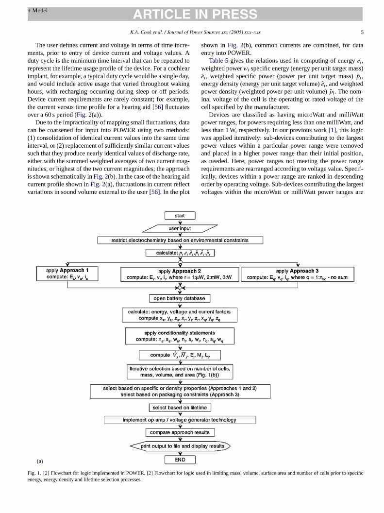
A flowchart for our algorithm is given inFig. 1(a) and (b);it is modified to reflect changes from our first work using thisapproach[1]. The user provides target values for mass, volume,a powerb sec-o ucedt
educed power demands by 50 and 58%, respectively[54,55].t must be noted, however, that power reduction frequeomes at the expense of speed of execution, bandwidth,
knd surface area, operational temperature, numbers ofundle locations, number of cycles, selection of primary orndary cells, and mass or volume optimization. We have red
he number of user inputs in comparison to our past work[1],

4 K.A. Cook et al. / Journal of Power Sources xxx (2005) xxx–xxx
Table 3Typical discharge current requirements for microelectronics[44–49]
Microelectronic device Technology Size Power–current–voltagerequirements
Power source
Micro magnetic sensor Mineral insulated (Ml) sensorconstructed using CMOS ICmultivibrator circuit
Wirediameter = 30�m,length = 2 mm
0.5–5 mW (pulsecurrent = 30 mA)
External power supply
Colpitts transmitter Five-turn dielectric suspendedinductor was fabricated using adissolved wafer process
Colpitts oscillatortransmitter(5 mm× 5 mm area)each coil is 25�mwide, 5�m thick
100�A with drivingvoltage = 3.0 V
Operated with 3 Vbattery
Si-based micro-machinedgas sensor
Sensor array was fabricated using apost-process micro-machiningtechnique of standard CMOS process
Thickness = 1.2�m,activearea = 80�m× 80�m
9 mW of drive powerwith 2.0 V drivevoltage
External power supply
Amperometric potentiostat Potentiostat uses an ADC circuit thatallos the direct conversion ofelectrode current in nanoampererange to low-voltage CMOS levelsusing four operational applifiers
Volume < 3 cm3 0.65 mW, 260�A and2.5 V
3 V lithium coin cellsuggested
Electrothermal actuator MEMS polysilicon surfacemicromachined electroactuator usesresistive Joule heating to generateexpansion and movement
462.5�m× 15�m× 129.5�m∼7–25 mW Externalprogrammable powersupply
Three-axial force sensor Si-based three-axial force sensor tobe used in a flexible smart interfacefor biomechanical measurements
2.3 mm× 2.3 mm× 1.3 mmsensors haveimplantedpiezoresistors that are6�m× 30�m
10–1 mW inputvoltage = 3.3 V
External power supply
wherein users were required to specify target values for the massand volume for each power range. Instead, these values are calcu-lated based on the maximum number of cells for each approachspecified by the user. Specifically, the target volume,Vi , andmass,Mi , for each power range are computed from the expres-sions
Vi = Ni
NtotalVsys i =
1 for microWatt power range
2 for milliWatt power range
3 for Watt power range
(1)
and
Mi = Ni
NtotalMsys i =
1 for microWatt power range
2 for milliWatt power range
3 for Watt power range
(2)
whereNi (i = 1, 2, and 3) is the target number of cells for themicro-, milli- and Watt power ranges, respectively,Ntotal is thetotal number of cells,Vsys is the total volume andMsys is thetotal mass of the desired power supply.
Table 4Typical discharge current requirements for common commercial electronics[42]
Device Current drain (mA)
Cassette recorders 70–130 (low) 90–150 (medium) 100–200 (high)Disk players 100–350Calculators (LCD) <1Cameras 800–1600 (photo flash) 200–300 (autowind) 500–1600 (digital cameras)Cellular phones 300–800Camcorders 700–1000Computers 400–800 (palm held) 500–1500 (note book) 800–1000 (laptop)Fluorescent lamp 500–1000Flashlight 100–700Memory 0.001Remote control 10–60Radios: 9 V battery 8–12 (low volume) 10–15 (medium volume) 15–45 (high volume)R )WSMT
adios: cylindrical battery 10–20 (low volume)alkmanmoke detector 0.010–0.015 (background)otorized toysV: portable
20–30 (medium volume) 30–100 (high volume200–300
10–35 (alarm)600–1500400–700
K.A. Cook et al. / Journal of Power Sources xxx (2005) xxx–xxx 5
The user defines current and voltage in terms of time incre-ments, prior to entry of device current and voltage values. Aduty cycle is the minimum time interval that can be repeated torepresent the lifetime usage profile of the device. For a cochlearimplant, for example, a typical duty cycle would be a single day,and would include active usage that varied throughout wakinghours, with recharging occurring during sleep or off periods.Device current requirements are rarely constant; for example,the current versus time profile for a hearing aid[56] fluctuatesover a 60 s period (Fig. 2(a)).
Due to the impracticality of mapping small fluctuations, datacan be coarsened for input into POWER using two methods:(1) consolidation of identical current values into the same timeinterval, or (2) replacement of sufficiently similar current valuessuch that they produce nearly identical values of discharge rate,either with the summed weighted averages of two current mag-nitudes, or highest of the two current magnitudes; the approachis shown schematically inFig. 2(b). In the case of the hearing aidcurrent profile shown inFig. 2(a), fluctuations in current reflectvariations in sound volume external to the user[56]. In the plot
shown inFig. 2(b), common currents are combined, for dataentry into POWER.
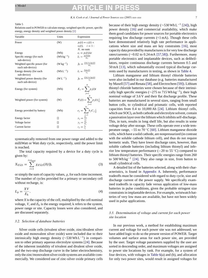
Table 5gives the relations used in computing of energyei,weighted powerwi specific energy (energy per unit target mass)ei, weighted specific power (power per unit target mass) ˜pi,energy density (energy per unit target volume) ˆei, and weightedpower density (weighted power per unit volume) ˆpi. The nom-inal voltage of the cell is the operating or rated voltage of thecell specified by the manufacturer.
Devices are classified as having microWatt and milliWattpower ranges, for powers requiring less than one milliWatt, andless than 1 W, respectively. In our previous work[1], this logicwas applied iteratively: sub-devices contributing to the largestpower values within a particular power range were removedand placed in a higher power range than their initial position,as needed. Here, power ranges not meeting the power rangerequirements are rearranged according to voltage value. Specif-ically, devices within a power range are ranked in descendingorder by operating voltage. Sub-devices contributing the largestvoltages within the microWatt or milliWatt power ranges are
Fe
ig. 1. [2] Flowchart for logic implemented in POWER.[2] Flowchart for logic usnergy, energy density and lifetime selection processes.
ed in limiting mass, volume, surface area and number of cells prior to specific

6 K.A. Cook et al. / Journal of Power Sources xxx (2005) xxx–xxx
Fig. 1. (Continued).
Fig. 2. (a) Current vs. time data for ‘Digital Aid X’ hearing aid tested by Denis Carpenter of Rayovac[56]. (b) Data after data coarsening, for input into POWER.
K.A. Cook et al. / Journal of Power Sources xxx (2005) xxx–xxx 7
Table 5Relations used in POWER to calculate energy, weighted specific power, specificenergy, energy density and weighted power density[1]
Variable Units Expression
Power (W) pi(t) = ci(t) ×vi(t), i = 1 :N, no sum
Energy (Wh) ei = pi(t)�t
Specific energy (for eachsub-device)
(Wh kg−1) ei = pi(t)�tmx
Weighted specific power (foreach sub-device)
(W kg−1) pi = (�t/tT )pi(t)mx
Energy density (for eachsub-device)
(Wh L−1) ei = �tpi(t)vx
Weighted power density (foreach sub-device)
(W L−1) pi = (�t/tT )pi(t)vx
Energy (for system) (Wh) Ex =N∑
j=1
pj(t)t
Weighted power (for system) (W) Px(t) =N∑
j=1
pj(t) ttT
Energy provided by battery (Wh) ej =tT∑
j=1
bjCjttT
Energy factor [] xj = Exej
Voltage factor [] yj = Vxbj
Current factor [] zj = ixij
systematically removed from one power range and added to thmilliWatt or Watt duty cycle, respectively, until the power limitis reached.
The total capacity required by a device for a duty cycle isgiven by:
XE521 =t=ttotal∑t=1
χE521(I(t)), (3)
or simply the sum of capacity values,χ, for each time increment.The number of cycles provided for a primary or secondary cellwithout recharge, is:
Lp = XV
Ek, (4)
whereX is the capacity of the cell, multiplied by the cell nominalvoltage,V, andEk is the energy required; k refers to the system,power range or site. Capacity losses were also considered, anare discussed separately.
3.2. Selection of database batteries
Silver oxide cells (trivalent silver oxide, zinc/divalent silveroxide and monovalent silver oxide) were included due to theirintrinsically high energy density (∼530 Wh L−1) in compari-son to other primary aqueous electrolyte systems[24]. Becauseo de,a istryo comm ells
because of their high energy density (∼530 Wh L−1 [24]), highpower density[16] and commercial availability, which makethem good candidates for power sources for portable electronicsrequiring low discharge currents (<1 mA). Though these cellshave demonstrated relatively high rate performance in appli-cations where size and mass are key constraints[16], mostcapacity data provided by manufactures is for very low dischargerates/currents (∼0.02 to 0.24 mA[57,58]). Furthermore, manyportable electronics and implantable devices, such as defibril-lators, require continuous discharge currents between 0.5 and50 mA [13], which substantially exceed typical discharge cur-rents used by manufacturers in testing, as shown inTable 4.
Lithium manganese and lithium thionyl chloride batterieswere also included in our database (e.g. batteries manufacturedby Maxell[57] and Renata[58], and Electrochem[59]). Lithiumthionyl chloride batteries were chosen because of their intrinsi-cally high specific energies (∼275 to 715 Wh kg−1), their highnominal voltage of 3.6 V and their flat discharge profile. Thesebatteries are manufactured in several sizes, ranging from smallbutton cells, to cylindrical and prismatic cells, with reportedcapacities from 0.4 to 10,000 Ah[24]. Lithium thionyl cells,which use SOCl2 as both cathode and electrolyte solvent, containa passivation layer over the lithium which inhibits self-discharge.This, in turn, results in long shelf life, but also results in somevoltage delay after storage. These cells operate over a wide tem-p ◦ ec ntrastw uireh , thans fe-r ol 260t tos
har-a et andd am-i assb sizec bat-t idelyu
3s
umc d; weh argetv videdb er ares ignedt m off nf for
f the inherent instability of trivalent and divalent silver oxind the two-step discharge curve in the latter electrochemnly the zinc/monovalent silver oxide systems are availableercially. We considered use of zinc-silver oxide primary c
e
d
,-
erature range,−55 to 70 C [60]. Lithium manganese dioxidells, which have a solid cathode, are nonpressurized (in coith the soluble cathode lithium cell), and thus do not reqermetic seals. They have lower discharge rates, howeveroluble cathode batteries (including lithium thionyl) and inior low temperature performance (−20 to 55◦C) compared tithium thionyl batteries. Their specific energies range fromo 500 Wh kg−1 [24]. They also range in size, from buttonmall cylindrical cells.
A detailed list of the batteries selected, along with their ccteristics, is found inAppendix A. Inherently, performanc
radeoffs must be considered with regard to duty cycle, sizeischarge current of the power supply. We specifically ex
ned tradeoffs in capacity fade versus application of low-matteries in pulse conditions, given the probable stringentonstraints in implantable devices. For example, wristwatcheries of very low mass are available, but have not been wsed in pulse applications.
.3. Determination of voltage and current for each powerite location
In our previous work, a method for establishing maximurrent and voltage for each power site was not addresseave added logic to do so the present version of POWER. Tolumes and surface areas for each power site, are proy the user. Target voltage parameters supplied by the usorted in descending order, and maximum voltages are asso power site locations by rank. For example, for a systeour devices, with voltages inTable 6(a) and (b), and allocatioor only two power sites, would result in assigned voltages

8 K.A. Cook et al. / Journal of Power Sources xxx (2005) xxx–xxx
Table 6Sample system of four devices with varying voltages, used to demonstrate allocation of voltage values for power site locations; and the resulting assignment ofvoltage values for two power site locations, based on the system defined
Device Voltage (V) Current (mA)
Device #1 15.0 0.001Device #2 3.0 2.0Device #3 5.2 1000Device #4 6.0 0.25
Power bundle site Volume (cm3) Surface area (cm2) Voltage (V) Current (mA)
1 12.0 60.0 15 7502 5.0 20.0 6.0 250
power sites 1 and 2, of 15 and 6.0 V, respectively. The energyEi required by each site is simply the volume fraction of the sitemultiplied by the total energy of the system. The weighted powerrequired for each site,Pi, is similarly the area fraction of the sitemultiplied by the total system power. The current for each powersite is obtained by multiplying area fraction of the site by themaximum current at that site. Thus, the current for each powersite inTable 6would be 0.75 and 0.25 A for sites having areasof 60 and 20 cm2, respectively (Table 6). The surface area foreach cell in the database refers to the total surface of the cell,and not one specific side or face.
3.4. Estimation of capacity fade, for primary andsecondary cells
Capacity fade as a function of both discharge current andcycle number was estimated, where possible, using expressionsrelating capacity fade as a function of cycle from online batterymanufacturer data[3,22,56–59,61]. Data used for the empiricalregression lines were inclusive of our experimental data andvalues obtained from the manufacturer[3,22,56–59,61]. At leastfour data points (e.g. capacity value as a function of current) wereused in each plot.
For example, capacity for an Energizer 521 cell was deter-mined via curve-fit of manufacturer-reported data[61] to be:
χ
wr (limi tor rren[ tablef e asa ands
sec-o an be ertaic
P
The total capacity a cell can provide, including all rechargecycles, is thus:
XR =c=total cycles∑
c=1
PcX(t) (7)
This capacity was used by our algorithm to determine the totalnumber of cycles a particular cell can provide for a specific dutycycle, as:
LS = XR
Ek. (8)
The capacity value computed for non-rechargeable systems wasused for the energy factor calculation. Cycle time and recharg-ing of cells is incorporated into POWER via Eqs.(6)–(8) foraccurate determination of battery solutions’ cycle life. Capac-ity, X(t), is first computed as a function of discharge current overtime, per Eq.(3); total capacity as a function of cycle number isthen computed via Eq.(7). Pc drops monotonically with cyclenumber; available capacity thus also drops monotonically withincreasing cycle number.
We also generated our own data on primary (i.e. non-chargeable cells) silver oxide cells to estimate capacity fade.Cells were discharged at currents one and two orders of magni-t rrents,f ctron-i eedoS t dis-c md e. Inc minald a solu-t
a rrenta uousr ltagew than1 d inF d the
E521 = −2.45 ln(I(t)) + 3.26, (5)
hereI is the discharge current for time incrementt. Similarelations were generated for all cases using polynomialsted to third order), logarithmic or power decay functionseflect the decay of capacity with increased discharge cu24–27]. Correlation factors of >0.80 were deemed accepor implementation. This method of computing capacity fad
function of discharge current was used for both primaryecondary cells.
Capacity fade as a function of cycle was used only forndary cells. Percent capacity fade as a function of cycle cxpressed as the ratio of capacity provided by a cell at a cycle by the maximum capacity the cell can provide, per
c = X(ci)
X(c1). (6)
-
t
en
ude above the manufacturer-recommended discharge cuor two reasons. First, many household appliances and elecs (detailed inTable 4) require discharge currents that excperational values provided by many manufacturers[57,58,61].econd, our algorithm requires additional batteries to meeharge currents (current factor,xi) that exceed the maximuischarge current allowed for each battery in the databasases where manufacture data are provided for small noischarge currents, additional batteries are suggested as
ion, to account for losses due to high rate operation.Silver oxide primary cells (Table 7) were tested to inform
simple model for the relationship between discharge cund capacity. All cells were subjected to constant continesistance discharges, wherein the initial open-circuit voas approximately 1.55 V and then end voltage was less.0 V. A schematic of the experimental setup is illustrateig. 3. Voltage per second was recorded for each cell, an

K.A. Cook et al. / Journal of Power Sources xxx (2005) xxx–xxx 9
Table 7Characteristics of silver oxide cells tested
Manufacturer Part number Diameter (mm) Height (mm) Mass (g) Resistances tested (k�)
Energizer 337 4.80 1.65 0.13 1.25, 1.50, 1.875Duracell D379 5.79 2.15 0.23 1.25, 1.50, 1.875Maxell SR516SW 5.80 1.65 0.20 1.25, 1.50, 1.875Maxell SR616SW 6.80 1.65 0.30 1.25, 1.50, 1.875Renata 337 4.80 1.65 0.12 100,6.8, 1.0,0.55Renata 377 6.80 2.66 0.40 0.55, 1.0,2.5, 6.8, 100Renata 364 6.80 2.15 0.32 0.55, 1.0,2.5Renata 317 5.80 1.65 0.18 0.55, 1.0,2.5,6.8Renata 319 5.80 2.70 0.29 0.55, 1.0,2.5, 6.8Renata 321 6.80 1.65 0.25 0.55, 1.0,2.5,6.8
discharge current:
I(t) = b(t)
R(9)
was determined from the quotient of voltage per unit time,b(t)and resistance,R. The average capacity for each cell was com-puted as the product of the average current,Iavg and total timeof operation:
Cavg = Iavg × ttotal (10)
from an initial voltage of 1.55 V to a cutoff voltage of 1.2 V.Cells were tested at various resistances, to allow curve-fit of aplot of capacity versus discharge current.
3.5. Case studies: fully implantable hearing prosthesis
We selected two fully implantable hearing prostheses as casestudies. The first was a mechanical stimulator for the tym-panic membrane, the TICA (LZ 3001) device[5–8], designedby researchers at Tubingen University. Specifications on thedevice’s power profile are listed inTable 8.
The second testbed was the WIMS-ERC Amadeus CochlearImplant [9–11,62,63], developed by researchers at the Univer-sity of Michigan. Specifications on the device’s power profileare listed inTable 9.
3
urat ting
typographical errors in our original work[1], these values areshown asTable 10(a) and (b). Cells can be placed in combina-tions of series and/or parallel according to energy (x), voltage(y) and current (z) factors (Table 10(a) and (b)). Factors (equa-tions contained in our previous work[1]): x, y andz are ratios ofsystem requirements (energy, voltage and current, respectively)to nominal cell values. Variables,n ands represent the system-required total number of cells, and number of cells in series,respectively. Cells can be placed in parallel to meet dischargecurrent and energy requirements, thus,w and u represent thetotal numbers of cells placed in parallel, and required to meetenergy requirements, respectively.
Factors greater than 1 require additional cells to satisfyenergy, voltage and discharge system requirements. For exam-ple, for ay of 2, two cells, in parallel, are required to meet thesystem voltage requirement.Table 10(a) and (b) are circuit dia-grams illustrating combinations of cells in series and/or parallel.In some cases, additional cells necessary to meet energy require-ments simultaneously result in satisfaction of discharge currentrequirements, e.g.z = 5,y = 3 andx = 2 (Table 10(b)).Table 10(a)and (b) also contain circuit diagrams illustrating cells in seriesand/or parallel associated with various combinations ofx, y andz values.
After batteries were configured in series or parallel arrange-ments according to the three approaches, mass, volume, surfacearea, and number of cells in the configuration were exam-ie ps( aintso a and
istan
.6. Conditionality statements
Conditionality statements were used to determine configion of the cells (series, parallel or a combination). Correc
Fig. 3. Experimental setup for res
-
ned. This portion of the algorithm is circled inFig. 1(a), andxpanded with additional detail inFig. 1(b). These iterative steFig. 1(b)) were implemented to enforce user-defined constrn maximum number of cells per configuration, surface are
ce testing of primary silver oxide cells.

10 K.A. Cook et al. / Journal of Power Sources xxx (2005) xxx–xxx
Table 8Input parameters for the Tubingen TICA (LZ3001)[5–8] tympanic membrane mechanical stimulator
Electronic components Input current (mA) Input voltage (V) Time interval (s)
Tubingen University—TICA implant—16 h operationMicrophone 0.05 1.25 60Signal processor 0.4–0.6 1.25 60Amplifiers 0.4 1.25 60Memory (monitoring) 0.1a 1.25 60Signal receiving circuit 0.1 1.25 60
Total time 16 h
Number of cycles 960 Number of power bundles 2Surface area of each bundle site 1.0 cm2 Volume of each power bundle 1.0 cm3
Total area 2.0 cm2 Total volume 2.0 cm3
a Value corrected from original reference.
mass (mass prioritization) or volume (volume prioritization),and also to compute the best solutions available, even if they didnot meet user requirements.
Table 1(b) schematically shows the methodology by whichbattery solutions determined based on user-supplied mass orvolume prioritization. Specifically, if the number of battery solu-tions in the database meeting the mass or volume requirements,Nctr, specified by the user is greater than 10, then the number ofbatteries meeting the minimum requirement for number of cellsin the battery solution is determined. So, battery solutions that donot meet the mass or volume requirements are eliminated fromthe pool of solutions that advance to the next step of analysis.However, if insufficient solutions (Nctr = 10) meet the mass orvolume requirements, solutions that otherwise would have beeneliminated are allowed to advance to the next stages of analysis.
Specifically, the number of configurations within eachapproach that satisfy the mass (mass prioritization) or vol-ume (volume prioritization) target values are counted (Nctr,r forApproach 1,Nctr,i wherei = 1, 2 and 3 for micro-, milli- and Wattpower ranges; andNctr,s, wheres = 1:n loc). If Nctr,i is less than10, a new target mass or volume is determined from the productof minimum mass/volume of all battery configurations and 1.25.For numbers of configurations that do not adhere to the maxi-mum number of cells, nctr, less than 10, new target values forthe maximum number of cells are determined by multiplying theminimum mass/volume of all configurations by 1.25. The codei ts an1 . Thn lumea
Nnctr comis less than 5, both mass/volume and maximum numberof cells targets values are multiplied by 1.10 and iterated. Thenumber of cell configurations meeting the surface area, actr, ischecked and iterated in a similar manner, however, only two cellconfigurations must meet the surface area requirement (Fig 1(a)and (b)).
3.7. Cost analysis
Although not used as a constraint, we did examine the costof each power solution generated for the test cases. All specifi-cations for batteries included in the database were readily foundonline. In some cases, purchase of a large number of cells wasrequired to reduce cost per piece.Appendix Aincludes batterycell characteristics, e.g. mass, volume, total surface area, elec-trochemistry, shape and cost for purchases on a per piece basis.
4. Results
4.1. Experimental characterization of capacity fade
Primary silver oxide cells exhibited flat voltage dischargecurves and operated at a nominal voltage of 1.55 V, as expected.An example of a discharge at a current of 0.8 mA is shown inFig. 4 (Maxell 516), with a corresponding plot of curve-fits forcapacity as a function of various discharge current shown inF tin-u r timew acitya luded
TI t
E l (s)
W
terates until at least 10 cells meet the mass/volume targe0 meet the number of cells per configuration requirementsumber of cells that meet both requirements for mass/vond number of cells per configuration is determined,Nnctr com. If
able 9nput parameters for the WIMS-ERC Amadeus[9–11,62,63]cochlear implan
lectronic components Input current (mA)
IMS-ERC—Amadeus Cl—16 h operationElectrodes 4.10Microcircuits 0.08
Number of cycles 960Surface area of each bundle site 1.0 cm2
Total area 2.0 cm2
deig. 5. A number of silver oxide cells were subjected to conous constant resistance loads; in each case, voltage oveas recorded. An expression for the line best fitting the caps a function of discharge current was determined and inc
Input voltage (V) Time interva
3.00 603.00 60
Total time 16 h
Number of power bundles 2Volume of each power bundle 1.0 cm3
Total volume 2.0 cm3

K.A. Cook et al. / Journal of Power Sources xxx (2005) xxx–xxx 11
Table 10Revised conditionality statements
(a) Condition Expression Examples and circuit diagram x y z nj sj Wj andUj
z < x < y
nj = yz + |x − z|, sj = y,Wj = z, uj = x
2 3 1 4 3 1 and 2
3 5 2 11 5 2 and 3
x = y > z 2 2 1 3 2 1 and 2
3 3 2 7 3 2 and 3
y < z < x andy �= 1 4 2 3 7 2 3 and 4
z < y < x 3 2 1 4 2 1 and 3
5 3 2 9 3 2 and 5
y = z < x andy �= 1 4 2 2 6 2 2 and 4
y = z < x andy = 1 nj = yz + |x − z|, sj = y,Wj = 0, uj = x
3 1 1 3 1 0 and 3
y < z < x andy = 1 3 1 2 3 1 0 and 3
(b) Condition Expression Examples and circuit diagram x y z nj sj Wj
x = y = z
nj = yz, sj = y, Wj = z
1 1 1 1 0 0
2 2 2 4 2 2
4 4 4 16 4 4
x < y < z 1 2 3 6 2 3
2 3 5 15 3 5
y < x < z 2 1 3 3 1 3
3 2 5 10 2 5
x < z < y 1 3 2 6 3 2
1 5 3 15 5 3
x = y < z 1 1 2 2 1 2
2 2 3 6 2 3

12 K.A. Cook et al. / Journal of Power Sources xxx (2005) xxx–xxx
Table 10 (Continued )
(a) Condition Expression Examples and circuit diagram x y z nj sj Wj andUj
x = z < y 1 2 1 2 1 2
2 4 2 8 4 2
x = z > y 2 1 2 2 1 2
3 2 3 6 2 3
y = z > x 1 2 2 4 2 2
2 4 4 16 4 4
Fig. 4. Voltage vs. time curve obtained from constant resistance testing of aMaxell 516SW silver oxide cell.
Fig. 5. Sample empirical fit of capacity as a function of discharge current forthe Maxell 516SW silver oxide cell.
in our code.Table 11(a) and (b) provide the expression foundfor each battery tested.
4.2. TICA (LZ 3001) device: 16-h duty cycle
Results for the 16-h operation of the TICA (LZ 3001) deviceare shown inTable 12. The first of the two tables show the bestsecondary power solutions. Identical results were obtained forthe mass and volume prioritization. Application of Approach1 resulted in a system comprised of a single cell, the QuallionQL0170E, with a mass of 6.0 g and a volume of 2.62 cm3. Thelifetimes, in terms of cycle number, were calculated to be∼28and 25,800, for use of the cell as a primary and secondary source,respectively.
Application of Approach 2 resulted in selection of twoQuallion-QL0170E cells (6.0 g and 2.62 cm3 per cell), one forthe micro power range and one for the milli power range, result-ing in a total system size of 12 g and 5.24 cm3. The lifetimes, interms of cycle number, for both micro- and milliWatt powerranges were 53,700 and 49,600, respectively, when rechargecycles were included.
Using Approach 3, two Quallion-QL0170E cells wereselected (6.0 g and 2.62 cm3), one for each power site, resultingin a total mass and volume of 12 g and 5.24 cm3. The lifetimes,in terms of cycle number, were both 51,640 for each powers ndarys threeA ed fort
m tod OneR ta 377c owers vol-u ltedi cellD lectedf neR riori-
ite, assuming recharge, i.e. use of the batteries as secoources. When volume was selected as the priority, all thepproaches provided the same results as those determin
he mass priority case.For comparative purposes, we also used our algorith
etermine the best systems for primary power supplies.enata 380 cell was selected for Approach 1 and two Renaells were selected for Approach 3, one in each available pite. Identical solutions were obtained for both mass andme prioritization. For Approach 2, mass prioritization resu
n selection of a lighter cell for the microWatt range (Dura377, mass equal to 0.4 g); a Renata 380 (1.2 g) cell was se
or volume prioritization. For the milliWatt power range, oenata 380 cell was selected for both mass and volume p

K.A. Cook et al. / Journal of Power Sources xxx (2005) xxx–xxx 13
Table 11Empirically-determined capacity vs. discharge current, for several silver oxide cells tested
Manufacturer Part number Resistance (k�) Capacity (mAh) Current (mA) Expression
(a)
Energizer 3371.25 1.01 1.13 Capacity = 2870l2
− 8.9l + 0.008,R2 = 0.99
1.50 1.99 0.951.88 2.17 0.78
Maxell SR516SW1.25 5.00 1.18 Capacity = 4228l2
− 10.77l + 0.012,R2 = 0.99
1.50 5.00 0.98188 6.00 0.79
Maxell SR616SW1.25 6.78 1.18 Capacity = 3854l2
− 11.84l + 0.015R2 = 0.99
1.50 6.96 0.991.88 8.45 0.80
Duracell D3791.25 0.13 1.03 Capacity = 14200l2
− 28.37l + 0.015,R2 = 0.99
1.50 1.10 0.891.88 1.26 0.71
Renata 3150.55 7.83 2.63 Capacity = 1359l2
− 8.28l + 0.02,R2 = 0.96
1.00 9.72 1.472.50 16.9 0.60
Renata 317
0.55 1.58 2.46Capacity =−0.002ln(l) − 0.009,R2 = 0.99
1.00 2.37 1.432.50 3.64 0.606.80 6.15 0.22
(b)
Renata319 0.55 2.68 2.53 Capacity =−0.004 ln(l)
− 0.02,R2 = 0.991.00 4.48 1.44
Renata321 0.55 1.18 2.53
Capacity = 0.0001l−05,R2 = 0.97
1.00 1.28 1.432.50 3.22 0.60
Renata337 0.55 1.89 2.52 Capacity = 1398l2
− 6l + 0.008,R2 = 1.0
1.00 2.54 1.366.80 6.83 0.22
Renata364 0.55 0.33 2.58
Capacity = 10−6l−09,R2 = 0.97
1.00 0.49 1.452.50 0.62 0.60
Renata
377 0.55 1.78 2.60
Capacity = 0.02e−995,R2 = 0.95
1.00 4.59 1.432.00 1.23 0.756.80 12.90 0.23
Renata397 0.55 14.0 2.63
Capacity = 0.032e−328,R2 = 0.99
1.00 18.50 1.482.50 26.90 0.61
tization. The cycle life resulting from application of Approach1 was 5.08; each cycle was 16 h in length, resulting in a totallife of just over 3 days. The solution resulting from applicationof Approach 2 for the microWatt range, provided 3110 cyclesof 16 h (∼5.66 years) for mass prioritization and 10,200 cyclesof 16 h (∼ 22 years) for volume prioritization. For the milliWattpower range, a lifetime of 9.78 cycles (∼6.7 days) was computedfor both mass and volume prioritization. Approach 3 provided alifetime of approximately 4.4 cycles for both prioritizations.
4.3. WIMS-ERC Amadeus CI: 16-h operation
Results for a 16-h duty cycle for the Amadeus CI are given inTable 13(secondary cells). When mass was prioritized, applica-
tion of Approach 1 provided a solution consisting of a single cell,the Quallion QL0170E, of size 6.0 g and 2.62 cm3. The num-ber of cycles predicted was 3.51, without recharge and 3210,with recharge. Application of Approach 2 resulted in selec-tion of two cells, one Quallion-QL0100E cell (with a mass of4.0 g and volume of 1.81 cm3) for the microWatt range, and oneQuallion-QL0170E cell (with a mass of 6.0 g and volume of2.62 cm3) for the milliWatt range; the total mass and volume ofthe system were 10 g and 4.43 cm3, respectively. The calculatedlifetime for the battery selected in the microWatt range was 105cycles as a primary source, and 96,400 as a secondary source.Application of Approach 3 resulted in selection of two Ultralife-UBC641730 cells, one for each power site, resulting in a totalmass and volume of 9.0 g and 4.46 cm3. In this last case, we cal-

14 K.A. Cook et al. / Journal of Power Sources xxx (2005) xxx–xxx
Table 12Binning of devices
Range Device Power (mW) Voltage (V)
(a): Binning of devices into micro and milliWatt power ranges, before anyre-arrangement
Microwatt1 0.006 1.52 0.950 2.03 0.750 7.0
Total 1.71
Milliwatt4 1.5 15.05 2.5 16.0
Total 4.0
(b): Initial binning of devices within power ranges for a sample systemaccording to power value
Microwatt1 0.006 1.53 0.750 7.0
Total 0.756
Milliwatt4 1.50 15.05 2.50 16.02 0.95 2.0
Total 4.95
(c): Final binning of devices within power ranges, for a sample system,according to voltage value
Microwatt1 0.006 1.52 0.950 2.0
Total 0.956
Milliwatt4 1.50 15.05 2.50 16.03 0.750 7.0
Total 4.75
culated a lifetime of 7.34 cycles without recharge, and 3200 withrecharge.
When primary cells were examined for both mass and volumeprioritization computations, the same batteries were selectedwith application of Approaches 1 and 3. Three cells (Renata380) were selected for Approach 1 and six cells (Renata 377)were selected for Approach 3, i.e. three per power bundle. ForApproach 2 in the microWatt range, one Renata CR2032 (2.8 g)cell was selected in the case of mass prioritization and a RenataCN2450N (5.9 g) cell was selected for volume prioritization. Forthe milliWatt power range, three Renata 380 cells were selected.The cycle lifetime provided by Approach 1 was 1.9 cycles of16 h each (∼1.5 days). The system designed by application ofApproach 2 for the microWatt range, provided 173,000 cyclesfor mass prioritization and 712,000 cycles for volume priori-tization. For the milliWatt power range, calculated lifetime as1.9 cycles (∼1.5 day) for both mass and volume prioritization.Approach 3 provided a cycle lifetime of 1.65 cycles (∼1 day)for both prioritizations.
5. Discussion
We have implemented an algorithm into a turnkey batteryselection code, POWER, that can be used to design power supplysystems for a wide range of wireless devices. Our extensiono citya n ofc ed onv asedo
Table 13Solutions generated by POWER for the TICA prosthesis implant (secondary b
Manufacturer Part No. Total No. No. of cyclesbattery re-char
Tubingen TICA—mass priority—16 h of operationApproach 1 Quallion QL0170E 1 28.10
Approach 2Micro Quallion QL0170E 1 58.60Milli Quallion QL0170E 1 54.10Totals 2
Approach 3Site 1 Quallion QL0170E 1 56.30Site 2 Quallion QL0170E 1 56.30Totals 2
Tubingen TICA—volume priority—16 h of operationApproach 1 Quallion QL0170E 1 28.10
Approach 2Micro Quallion QL0170E 1 58.60Milli Quallion QL0170E 1 54.10Totals 2
Approach 3Site 1 Quallion QL0170E 1 56.30Site 2 Quallion QL0170E 1 56.30Totals 2
f our original algorithm [] includes consideration of capas a function of discharge current, capacity as a functioycle number, assembly of devices within power ranges basoltage rather than power, and battery number limitation bn user input and rechargeability.
atteries)
(noge)
No. of cycles (batteryre-charge)
Total mass (g) Total volume (cm3)
25800 6.00 2.62
53700 6.00 2.6249600 6.00 2.62
12.00 5.24
51600 6.00 2.6251600 6.00 2.62
12.00 5.24
25800 6.00 2.62
53700 6.00 2.6249600 6.00 2.62
12.00 5.24
51600 6.00 2.6251600 6.00 2.62
12.00 5.24

K.A. Cook et al. / Journal of Power Sources xxx (2005) xxx–xxx 15
5.1. Batteries selected and their efficiency in the casesexamined
The flat discharge curves of the zinc/monovalent systemsmake them ideal for nearly constant voltage electronic appli-cations such as watches, calculators, hearing aids and cameras;typical capacities that range from 5 to 250 mAh[24]. Thesecells also have demonstrated long storage life, retaining morethan 95% of their initial capacity after a one year at room tem-perature. They also exhibit good low temperature performance,and deliver approximately 70% of their capacity at 0◦C and35% at−20◦C. Their optimal performance temperature rangeis from 0 to 55◦C [24]. The open-circuit, nominal and cut-off voltages of zinc-silver oxide cells are 1.5–1.6 V, 1.5 and1.0 V, respectively[16]. The TICA and Amadeus have maxi-mum discharge current and voltage values of 1.25 and 4.18 mA,3.0 and 1.25 V, respectively. The discharge currents requiredby these devices are smaller than majority of the devices listedin Table 4. However, the desired battery cycle lifetimes for theTICA and Amadeus are much longer than desired for majority ofthe devices listed inTable 4. Thus, in comparison to many othercommon electronics, our devices require batteries that are highin energy density and specific energy and much less demandingin regards to power density and specific power.
5.2. Key difference in power requirements for implanteda
torsd ulsep arger up ts CAa e vau h non
ed ot tingli g,2 ss,v es—Qc ass,v vi-r ,w divis icrom ist-i Ml nc on int aust owep highp highe tiono
Both the WIMS-ERC cochlear and EMT call for use ofeither lithium or lithium-ion electrochemistries because they fallwithin the high specific power and high specific energy powerrange for secondary batteries (Table 2(b)). However, complica-tions associated with the cycling behavior of secondary cellsmay make their application in implantable systems problem-atic. Some workers (e.g.[8]) have identified several areas ofrisk for the use of lithium-ion, lithium polymer, nickel cadmiumand nickel metal hydride; similar problems are associated withlithium iodine cells used in cardiac pacemakers[8]:
1. Cell packaging leaks can result in loss of electrolyte, resultingin corrosion damage of electronics. All cell seals must adhereto the standard MIL STD 883D.
2. Outgassing of oxygen and hydrogen at high rates of dis-charge, cycling over an extended periods, or charge reversalfor certain arrangements of cells, can all lead to pressurebuildup and unavoidable deformation of cell housings inthese necessarily sealed systems.
3. High discharge rates and cycling for extended periods of timecan result in elevated temperatures that can lead to heatingof the external housing of the cell, implant and surroundingtissue.
Capacity fade and cell swelling in lithium primary cells dueto chemical reaction of the electrodes with the electrolyte and thep dp an-g hens m-ionc andA ) andv w-e tion,h ice,w icet sce-n n ofA
rateda , then ctor,i ptioni is sos udeh e as af hereA tteryr d byt idedb
oper-a b-l heat,i issi-p er nd
nd explanted or other systems
Presently, biomedical implants such as neurostimularug pumps and implantable defibrillators require high power and long battery life, wherein steady current dischange could be 0.5–50 mA, and pulse discharge could beeveral hundred mA[13]. The devices examined here, the TInd Amadeus, have maximum discharge current and voltages of 1.25 and 4.18 mA, 3.0 and 1.25 V, respectively, witoted spikes in the current profile.
Approach 1, a homogeneous power supply system bashe aggregate system profile, provided the best and, interesdentical solutions for both the TICA[5–8]and Amadeus (6.0.62 cm3, 1 cell [9–11]) implants in terms of smallest maolume and number of cells amongst the three approachuallion QL0170E, lithium polymer cell (6.0 g, 2.62 cm3, 1ell). The optimal solution using the same criteria of molume and number of cells, found for the WIMS-ERC enonmental monitor testbed from our previous work[1], howeveras obtained from Approach 2, power selection based onion of the power requirements based on power ranges of milli- and Watt power. In this work, a hybrid solution cons
ng of a thin-film lithium-free cell, 2 Ultralife UBC64130/PCithium-ion cells and 5 Ultralife UBC422030/PCM lithium-ioells were selected. Approach 1 provides the best solutierms of mass and volume for the implantable system bechere are no current, voltage or power spikes/pulses in the profile, thus eliminating the gains associated with the use ofower density and specific power materials for pulses andnergy density and specific energy materials for the flat porf the power curve.
,
o
l-
ny,
a
--,
er
s
assivation layer have led workers (e.g.[13]) to propose hybririmary battery systems of lithium iodine and lithium manese dioxide cells, to power implantable defibrillators. Wecondary cells were examined for our testbed cases, lithiuells were chosen for both the Amadeus and TICA devicespproach 1 provided the best results for mass (6.0 and 6.0 golume (2.62 and 2.62 cm3) for both cases, respectively. Hover, if lifetime is the foremost consideration in battery selecybrid solutions clearly offer the best result for TICA devherein battery cycle life for Approaches 2 and 3 were tw
he number of cycles (for both non-recharge and re-chargearios) calculated for the system resulting from applicatiopproach 1.This is not the case for the Amadeus device, which is ope
t a higher discharge current than the TICA device. Hereumber of duty cycles calculated, when recharging is a fa
s essentially the same for all approaches. The only exces for the microWatt range, wherein the discharge currentmall (80�A) that the number of cycles is an order of magnitigher than for the other cases. The impact of capacity fad
unction of cycle is seen in the solution for the Amadeus, wpproach 3 provides more duty cycles before requiring ba
echarge. However, the over number of duty cycles providehe configuration of two cells is nearly equal to those provy Approach 1.
We have considered the use of voltage regulators andtional amplifier to adjust for voltage in POWER. A pro
ematic effect of these components is the generation ofn implantable applications: in general, tissue can only date temperature gradients of less than 2◦C in the temperaturange of 37–41◦C [63]. Self-heating of voltage regulators a

16 K.A. Cook et al. / Journal of Power Sources xxx (2005) xxx–xxx
operational amplifiers does not entirely prohibit their use inimplantable devices, but does merit further investigation on thelimits of their usage.
5.3. Lifetime of power designs for applications studied
There are a number of valid reasons to select primary, versussecondary systems, for implantable applications, even if lifetimeis somewhat reduced. Chiefly, recharge of secondary systemsexposes the patient to potentially high currents, and introducesother possible system failures. As described in Sections4.2 and4.3, the best primary systems had significantly reduced lifetimeover the best secondary systems examined here (i.e. 28/25,800and 1.65/3210 battery cycles, for primary/secondary systems,respectively, for the TICA (3001) and WIMS-ERC when sub-jected to 16 h of operation). But the continuous developmentof new primary power sources, along with diminishing powerdemands in microcircuitry, may ultimately make primary sys-tems more attractive.
For the longer lifetime, hybrid secondary systems, a weak-link lifetime was reported, i.e. the lifetime of the shortest livedpower supply was reported as the system lifetime. This maybe rather overly conservative, since loss of low- or midrangepower might be reasonably compensated for by on-board cir-cuitry shunting to the high power system. In any event, a logicaland necessary step in hybrid systems is to develop a protocolf er, st rvind
ac-i ns.I loss( rallyc riese -l for1 s,t hasn veri ten-i tteryc stui lifet
ighe r syst caseo an3d idest tteryl them ach2 assa yclel profi
[TICA] and 0.24–12.3 mW [Amadeus]) to the WIMS-ERC-EMT (18�W to 3.69 W), the key design factor for the fullyimplantable system is battery cycle lifetime. Approaches 2 and3 provide higher battery cycle lives because the power require-ments are divided amongst power ranges (Approach 2) or powersites (Approach 3). These implantable devices have dischargecurrent requirements that are small in comparison to manyelectronic appliances, which generally require several hundredmilliWatts for operation (Table 4).
5.4. Effect of capacity loss profiles on selection of powerelements
Though generally, a nonlinear relationship between capac-ity and discharge current is expected[64,42]. Some work hasbeen done to interrogate this relationship in specific systems;for example, nonlinear degradation of capacity as a functionof discharge current in zinc-silver oxide cells appears to resultfrom reduced theoretical voltage and side reactions[65]. How-ever, at present, there is insufficient support from a broad rangeof electrochemical studies to support use of a single model.
Thus, in this present work, we considered polynomial, log-arithmic and exponential fits to best fit experimental data,obtained from our experiments and manufacturers’ publisheddata. The expressions are applicable within specific dischargeranges noted inTable 11, and we state emphatically that theser avioro
rrenta eene rger xam-po cano 5 k( fora limi-n ac .e. 100c
aluest y ver-s andu ty,a als ver-s acityi ercialc thusc
yclen ate ofb cityp com-p heret d tos
or warning systems on essential and nonessential powhat continuous diagnostics can be run in these life-preseevices.
We also examined limitations on lifetime due to capty losses, which in turn are linked to operating condition batteries, the level of acceptable irreversible capacityICL) greater than 20% over a 1–2 year period is geneonsidered tolerable in portable electronic device batte.g. personal computers and cellular phones[12], but a satel
ite battery must often retain 80% of its initial capacity8 years or more[12]. In the case of implantable system
he rate of battery capacity fade as a function of cycleot, to our knowledge, been previously examined. Howe
mplantable devices that prevent and/or limit life threang physical malfunction require higher standards for baapacity fade than devices, such as the ones we haveed here, where failure of the devices is not necessarilyhreatening.
Low discharge currents allow for optimal capacity from hnergy density cells. Approaches 2 and 3 provided superio
ems for the implantable devices, in terms of cycle life. In thef the TICA device, systems designed using Approaches 2required more cells, two QL0170E cells, resulting in∼50,000uty cycles (including re-charge cycles). Approach 2 prov
he best solution for the Amadeus device in terms of baifetime (∼96,400 cycles for microWatt and 3280 cycles for
illiWatt power ranges, respectively). So, although Approdoes not provide the optimal solution in terms of the m
nd volume for the implantable systems, gains in battery cife can be achieved with this technique. Since the powerles for both implants were small in comparison (65–750�W
og
,
,
d-
-
d
-
elationships are not meant to be used to extrapolate behutside of the bounds directly tested.
Consideration of capacity as a function of discharge cullowed for inclusion of batteries that would have otherwise bliminated, if only high capacity values at very low dischaates provided by manufacturers were considered. For ele, Energizer suggests a nominal battery load of 100 k� forperation of cell 337[61]; we demonstrated that these cellsperate at loads up to several magnitudes lower, e.g. 1.2�
Table 11(a) and (b)). Thus, this battery can be consideredpplications where it would have otherwise either been eated (from selection based on a 100 k� requirement), or inase wherein a larger number of batteries was suggested, iells, to meet a higher load.
Batteries were tested at lower discharge resistance vhan suggested by the manufacturer, to determine capacitus discharge currents, at high currents. Cell fabricationse of additives[66,67] both play key roles in cell capacis shown by the data inTable 11; cells having nearly identichape can exhibit very different capacities, e.g. Energizerus Renata 337 cells. Other important factors affecting capnclude storage time and temperature; as with any commell, these conditions cannot be fully known a priori, andannot presently be modeled.
Consideration of capacity fade as a function of both cumber and discharge current can provide a better estimattery cycle life. POWER calculates the fraction of caparovided by a cell with each cycle. These values are used toute the number of battery cycles provided per recharge, w
he battery configuration identified by POWER is expecteatisfy at least one duty cycle before recharge.

K.A. Cook et al. / Journal of Power Sources xxx (2005) xxx–xxx 17
5.5. Power range device allocations
Currently, POWER transfers devices to higher power rangesin order of descending voltage value, until the power rangerequirements are satisfied. POWER, does not, however, gothrough each combination of devices within a power rangeto determine which configurations result in the minimal num-ber, mass and volume of batteries; thus, though the solution isimproved over the original algorithm, it is not necessarily theoptimal one. In our prior work[1], power ranges were arrangedby first assigning portions of each device power profile intoappropriate power ranges, e.g. portions less than or equal to1 mW were assigned to the microWatt range, those greater thanor equal to 1 mW and less than one Watt were allocated to themilliWatt power range. Portions greater than one Watt wereassigned to the Watt power range. Arrangement of devices withinpower ranges according to voltage is effective because binningdevices with voltage requirements reduces the number of batter-ies placed in series or the number of op-amps/voltage generatorsneeded.
5.6. Power site considerations
The current method of assignment based on descendingranking of values led to some moderate system overdesign.F ltagr r sitel ofv 16 Vw m offi w-
ever, the number of batteries placed in series to accommodatethe voltage requirement could be reduced by placing both the 17and 16 V devices on one site, and the remaining three deviceson the other. Clearly, one site could be allocated to high voltageapplications and the other could be dedicated to lower voltageapplication.
Also, the current assigned to each power site by POWER isthe product of the surface area ratio (surface area of individualsite to the sum of site areas) and maximum required current. Ifthe resulting current is less than current requirements of devicessurrounding the site, additional power programming is requiredto combine current contributions from multiple sites. Obviously,this eliminates the benefits of a ‘stand-alone’ system. In the casesexamined here, the solutions provided by Approach 3 were quiteclose (in number of cells, mass and volume) to those recom-mended by Approaches 1 and 2. However, this was not the casefor the WIMS-ERC-EMT system, where values of mass and vol-ume were in close range of Approaches 1 and 2, but the numberof cells was 3.6 and 8.1 times those for Approaches 1 and 2.
5.7. Masses and volumes of power bundles
Since most manufacturers select power supplies post facto,Approach 3 provides a means for designing to meet specificsurface area and volume constraints. The surface area used inP f sur-f urfacea pris-m aces.T t thea
TS ndar
o.b
W
W
or example, suppose a system of five devices having voequirements of 17, 16, 3, 1.5 and 1.2 V required two poweocations (Table 12(a)–(c)). According to the current methodoltage assignment, a 17 V would be assigned to site 1 andould be assigned to site 2, which would require a minimuve lithium-ion cells for site 1, and five cells for site 2. Ho
able 14olutions generated by POWER for the Amadeus cochlear implant (seco
Manufacturer Part No. Total N
IMS—Amadeus (2005)—Cl—mass priority—16 h of operationApproach 1 Quallion QL0170E 1
Approach 2Micro Quallion QL0100E 1Milli Quallion QL0170E 1Totals 2
Approach 3Site 1 Ultralife UBC641730/PCM/UMC005 1Site 2 Ultralife UBC641730/PCM/UMC005 1Totals 2
IMS—Amadeus (2005)—Cl—volume priority—16 h of operationApproach 1 Quallion QL0170E 1
Approach 2Micro Quallion QL0100E 1Milli Quallion QL0170E 1Totals 2
Approach 3Site 1 Ultralife UBC641730/PCM/UMC005 1Site 2 Ultralife UBC641730/PCM/UMC005 1Totals 2
eOWER, however, is quite conservative, in that the value oace area recorded in the POWER database is the entire srea of the battery. Specifically, if the cell is a rectangularatic cell, the surface area is the sum of the area of all six fhis could lead to elimination of some cells that may meerea constraints on one side.
y batteries)
No. of cycles (noattery re-charge)
No. of cycles(battery re-charge)
Total mass (g) Total volume(cm3)
3.51 3210 6.00 2.62
105.00 96400 4.00 1.813.57 3280 6.00 2.62
10.00 4.43
7.34 3220 4.50 2.237.34 3220 4.50 2.23
9.00 4.46
3.51 3210 6.00 2.62
105.00 96400 4.00 1.813.57 3280 6.00 2.62
10.00 4.43
7.34 3220 4.50 2.237.34 3220 4.50 2.23
9.00 4.46

18 K.A. Cook et al. / Journal of Power Sources xxx (2005) xxx–xxx
Table 15Commercial biomedical devices[68–74]
Implantable device Medical condition Description of device Location of device Battery type Batterylifetime
Device volume (cc)and mass (g)
Cardiac pacemaker[64]
Conduction disorders(bradycardia); heartfailure
Three parts: pulsegenerator, one or twopacing leads and aprogrammer
Pacemaker: implanted underthe skin in upper chest,attached to one or two leads,which are placed next to or inthe heart muscle
Lithium iodine(primary)
2–10 years Pulse generator:8–16.6 cc, 18–37 g,leads: 46–58 cm
Cardiac defibrillator[42]
Ventricular and atrialtachyarrhythmi a andfibrillation
Three parts:defibrillator, one ortwo pacing leads anda programmer
Defibrillator: implanted underthe skin in the upper chestand is attached to one or twoleads, which are placed nextto or in the heart muscle
Lithium iodine(primary)
5 years Defibrillator:34–65 cc, 70–118 g,leads: 65–110 cm
Muscle stimulators[65]
Urinary and faecalincontinence;gastroparesis
Five parts:neurostimulator,programmer, anextension, a lead, andcontrol magnets
Neurostimulator: implantedsubcutaneously in theabdomen; lead placedadjacent to sacral nerve andattached to neurostimulatorwith extension
Lithium iodine(primary)
6–9 years Stimulator: 34 cc/42 g
Neurologicalstimulators[66]
Tremor (e.g. due toParkinson’s disease);pain management(lower leg and back)
Fully implantedsystem:neurostimulator, lead,extension,programmer, patientprogrammer, controlmagnet
Battery: implanted or wornexternally; neurostimulator:placed under skin in abdomenor chest cavity forParkinson’s; lead: placed nearspine for pain and in brain forParkinson’s, extensionconnects lead and thestimulator. If external systemis used, antenna must beplaced on skin with adhesivepatch to receive stimulation.
Externalsystem: 9 V,internal:lithium iodine(primary)
4–6 weeks(9 years)
Pulse generator:8–16.6 cc, 18–37 gleads: 46–58 cm
Cochlear implants Hearing disorders Consist internal andexternal components
Internal components: implantpackage implanted intemporal bone behind the earand electrode array isintroduced into inner ear(cochlear and labyrinth);external components:microphone, speechprocessor, and external cable[67]
AA batteriesor specializedlithium-ionbatteries
3–5 days Depends onmanufacturer
Monitoring devices Syncope; seizures Consist of electrodeson the surface thatsense the heartselectrical activity[68]
Recorder: placed in upperchest cavity; activator placedover heart after seizure tosave response information
Primary 1 year 8.8 cc
Drug pumps Pain caused by:cancer and itstreatments, injuries,diabetes;(external/internalpumps), - spasticity(intrathecal baclofenpumps)
Drug delivery systemto treat pain:implantable pump,intrathecal catheter,external programmer[69]
Pump: placed in abdominalsubcutaneous pocket;catheter: inserted intointrathecal space of spine,and tunneled under skin andconnected to the pump
Primary 3 years 10–80 cc
Left ventricular assistdevices
Heart failure; bridgeto transport orrecovery
Three components:pump, tube and powerpack
Pump device is implantedinto the upper part of theabdominal wall; tube fromthe pump fits into the leftventricle, and another tubeextends outside of the bodyand is attached to a smallbattery pack worn on ashoulder holster[70]
AC outlet ortwo 12 Vsecondarybatteries
5–6 h 119.025 cc, 280.66 g

K.A. Cook et al. / Journal of Power Sources xxx (2005) xxx–xxx 19
5.8. Extension of mass, volume and area target values
The code currently examines a minimum of 10 cells, e.g.if only one power solution meets the mass target set by theuser, an additional nine power configurations are examined toassure that the configuration also best meet the cell number, arealand specific energy requirements. The advantage of finding theminimum values of solution to meet target values of mass andvolume (10 cells), minimum number of cells (5 cells) and sur-face area requirements (2 cells) so that the algorithm does notconverge to a solution in one iteration. Thus, some battery con-figurations that meet the immediate mass or volume target donot necessarily provide the best specific energy or energy den-sity requirements. As the number of batteries in the databaseincreases, the need for increasing the target values in orderto have several available solutions should diminish. Selectingfrom among the 189 primary and 60 secondary cells in the bat-tery database (Appendix A), only 1 cell configuration met thevolume constraint and number of cells constraint (2 cm3 and 1cell) for the Amadeus, the UltralifeUBC322030. However, thesolution actually provided by POWER, the Quallion QL0170,though slightly higher in volume (2.6 cm3) provides a higherenergy density, of 268 Wh L−1, than does the Ultralife cell,223 Wh L−1.
Use of the total surface area of the cell does appear toeliminate batteries that may be feasible solutions if assem-b tionp ion,Q of1 l am reas tar-g no den-s ,01 -l w-e t thea ,3 ofl 730a es that
5
istryt iumc
plan(s hleai ri-c 2,t ume
provided a higher number of cycles than Approach 1, with andwithout recharge. It can be seen inTables 13 and 14that inall cases, there obviously significant increase in the number ofcycles when rechargeability is included, but also at low dischargecurrent, for the microWatt power range.
Because the CI operates at a higher voltage than the TICAdevice (3.0 V versus 1.25 V), the number of cells required for theformer case, for all Approaches. Although Approach 3 presentsthe smallest mass and volume for all approaches, it requires thehighest number of cells (six cells in two bundles); its inherentlygreater complexity makes it somewhat less appealing than theother approaches. The lifetime for all primary solutions waslimited to two cycles.
5.10. Cost analysis
From Appendix A, we see that on average, primary cellsmeeting the design constraints of the testbed are less expensivethan secondary cells. Further, most primary cells listed in thedatabase could be purchased readily online, while the secondarycells were often sold by whole sellers, who required purchaseof several hundred cells.
6. Conclusions
ewt tionw sec-o 0E( r-g ionc d tor ts forr there-f 00 ho time1 gnedi
na ne ofA ual-l ntso cro-p nge( ouldb e.A age(
tudya ellsd tageso s dont cells,a
led on a certain face or side. For example, the solurovided by POWER for the Amadeus, was the QuallL0170 lithium polymer cell, with a total surface area2.41 cm2. The target area was multiplied by 1.25 untiinimum of three cells met the new target surface a
ince none of the battery configurations met the originalet area constraint (1.0 cm2). This resulted in identificatiof three that met the volume, number of cells, energyity and new area constraints: the QuallionQL0110V (1 cell.0026 L, 153.62 Wh L−1 and 12.41 cm2), Quallion QL0100E
cell, 0.0018 L, 223.07 Wh L−1 and 9.34 cm2) and Qualion QL0170E (1 cell, 0.0026 L, 268.38 and 0.0026 L). Hover, a cell that was smaller in volume that did not meerea constraint was the UltralifeUBC641730 (1 cell, 0.0022 L30.41 Wh L−1 and 15.08 cm3). Because the surface area
argest face of the QL0110, QL0100, QL0170 and UBC641re 3.28, 1.248, 3.28 and 5.58 cm2, respectively, none met thurface area target, but all were closer to the target valueshe total surface area of the entire cell.
.9. Use of secondary versus primary cells
Among the primary cells, the most common electrochemhat our algorithm selected was the zinc-silver oxide; lithells were selected only for the microWatt power range.
Secondary cells selected by POWER for the cochlear im16-h operation) weigh less (<5 g, perTables 13 and 14) thanome power systems currently used by commercial cocmplants (Table 15 [68–74]), such as a 23 g alkaline cylindal cell (Energizer 391-AA[61]). As expected, Approachhrough at a penalty of slight increases in mass and vol
,
n
t
r
,
Based on the volume constraints (2 cm3) specified by thorkers at Tubingen university in Baumann group[5–8] for
he TICA (LZ 3001) device, the most suitable power soluould be the one identified by POWER for Approach 1,ndary cells. Consisting of just 1 cell type Quallion QL0172.62 cm3), this solution had a volume∼24% higher than the taet value, 2 cm3. As far as the lifetime is concerned, this solutan provide power for 28 cycles of 16 h each, without neeecharge (448 h, i.e. 18.6 days). Our algorithm also accounechargeability and capacity fade as cells are recharged;ore, the actual lifetime of 26,000 cycles of 16 h, i.e. 416,0r∼48 years of continuous use. This solution provides a life0 times longer than the Ni–Cd battery pack that was desi
n 1998[6,8] for the TICA device.For the WIMS-ERC Amadeus CI[9–11], the best solutio
mong the power sources our code identified was the opproach 2, secondary cells. Specifically, a cell type Q
ion QL0100E was selected to fulfill the power requiremef the microWatt range sub-devices (microcircuits and mirocessors) and a Quallion QL0170E cell for the milliWatt raelectrode array). The calculated lifetime of this system we 3280 cycles, corresponding to∼6.7 years of continuous usccounting for system shutdown during 8 of 24 h of us
sleep), the actual lifetime becomes∼10 years.The primary power solutions presented in the current s
llowed only a few days’ operation. Even so, primary ceserve further investigation as they present some advanver secondary power sources. Specifically, primary cellot rely on patient compliance to operate the implant[75]. Fur-
her, primary cells exhibit less outgassing than secondarynd thus pose fewer safety concerns in that area[17,18].

20 K.A. Cook et al. / Journal of Power Sources xxx (2005) xxx–xxx
Employing a larger volume battery may be a tradeoff thatwould allow higher reliability and safety. For a volume of∼6 cm3 (corresponding to 200 Renata 337 cells), a lifetime ofmore than 2 years can be achieved (∼500 cycles of 16 h). How-ever, incorporation of 200 cells would certainly increase theprobability of failure, which should be weighed in selection ofthe final design.
7. Future Work
7.1. Evolution of POWER
Currently the POWER battery database of consists of 189primary and 60 secondary cells. Additional batteries and othertypes of power supplies should certainly be included, to contin-uously take advantage of design innovations.
POWER currently calculates recharge cycles by assumingthat the cells are only recharged after at least one duty cycle,at 100% depth of discharge. However, batteries often providebetter cycle life when they are recharged at higher levels ofDOD. Thus, consideration of depth of discharge would poten-tially allow for less overdesign, and also allow for inclusionof power scavenging, wherein batteries could be charge duringperiods of low operation or sleep mode, increasing the numberof cycles provided by the system.
7
tablp rillat ss ot eralla vol-uu xidec s ofd ce-m
Most pacemakers consist of a pulse generator, pacing leads,and a controller. The pulse generator and controller have inter-mittent power profiles, which allow for longer battery lifetimesthan continuously-discharged devices. However, the solid elec-trolytes used in lithium technologies may prevent their use incochlear implants, due to required high discharge currents neces-sitated by the high internal resistance in such cells.
These devices, along with more recent devices employingtelemetry for physiological monitoring, often outside the clini-cal setting, have created a need for increased discharge current,although not necessarily greater energy capacity[14]. A num-ber of potential power sources have been examined for suchapplications, including biogalvanic cells[14]. Nuclear batteriessuch as those using plutonium 238 as a fuel[14] have also beenproposed. However, the extreme toxicity of these materials[14]may preclude their use, even under seal.
Other new elements to consider in novel power suppliesinclude containment of potentially harmful outgas by-products,containment of toxic active materials, implementation ofspecialized power management software, development ofcircuitry to monitor charge and tight control of discharge toprevent overheating, overcharge and charge reversal in cells.Operationally, change in temperature and volume during opera-tion, and heat generation, must also be considered. Future workwill include these, and other considerations, in continuouslyimproving our present tool.
owers beenp akesi user,a ity, top cor-p s andv owers
A
M
R
.2. New applications
Several workers have proposed the use of hybrid implanower systems for neurostimulators, drug pumps and defib
ors (all of which generally have power requirements in excehose required for pace makers) to combat problems genssociated with implantable batteries: lifetime, swelling (me change), self-heating and capacity fade[13]. Defibrillatorsse lithium-silver oxovanadium and lithium-manganese-dioells for power, which are operable at relatively high rateischarge[13]. Lithium iodine cells are commonly used in paakers[13,14].
anufacturer Part No.
enata
CR1927CR1025CR1216CR1220CR1225CR1616CR1620CR1632CR2016CR2025CR2032CR2320CR2325CR2430CR2440NCR2477N
e-fy
A systematic approach to selection and design of pystems for microelectronics has not, to our knowledge,reviously reported. The novelty of our procedure is that it t
nto account mass and volume design constraints set by thend user specific energy/power and energy and power densrovide concrete solutions. POWER is useful because it inorates all of the steps in power selection based on masolume, and provides a rational means for comparison of pystems.
ppendix A
[22,56–59,61]
Capacity (mAh);Xi(I)
XCR927= 7.92l2 − 10.97l + 34.4,R2 = 0.95XCR1025=−281.77l2 − 22.46l + 31.8,R2 = 1.0XCR1216= 68.86l2 − 39.5l + 26.6,R2 = 0.91XCR122=−69.75l2 − 1.93l + 38.2,R2 = 0.97XCR1225= 4.17l2 − 8.94l + 48.9,R2 = 0.97XCR1616=−7.12l2 − 2.33l + 50.2,R2 = 0.86XCR1620= 6.51l2 − 14.7l + 69.1,R2 = 0.93XCR1632=−1114.6l3 + 489.4l2 − 69.5l + 128.3,R2 = 1.0XCR2016=−41.97l2 − 0.40l + 82.2,R2 = 0.99XCR2025=−1632.7l3 + 765.5l2 − 101.0l + 173.9,R2 = 0.99XCR2032=−814.9l3 + 468.4l2 − 85.1l+240.1,R2 = 0.99XCR2320= 8.05l2 − 12.0l + 152.3,R2 = 0.98XCR2325=−685.68l3 + 320.2l2 − 46.0l + 192.7,R2 = 0.96XCR2430=−2.61l2 − 0.17l + 285.6,R2 = 1.0XCR2440N=−9.95l3 + 14.5l2 − 7.9l + 542.2,R2 = 1.0XCR2477N=−5.01l2 − 0.62l + 956.0,R2 = 0.99

K.A. Cook et al. / Journal of Power Sources xxx (2005) xxx–xxx 21
Manufacturer Part No. Capacity (mAh);Xi(I)
Electrochem
4301 X4301=−0.045l2 + 0.32l + 5280.7,R2 = 1.044230 X44230= 1.28l2 − 40.3l + 1775.6,R2 = 1.03B960 X3B960=−1.14l2+1.08l + 792.0,R2 = 1.03B880 X3B880= 9.28l2 - 62.7l + 1006.2,R2 = 1.03B940 X3B940=−0.156l2 − 1.09l + 1900.1,R2 = 1.04006 X4006= 60.61l2 − 56.4l + 63.0,R2 = 1.04030 X4030=−26.0 ln(l) + 534.2,R2 = 0.894161 X4161= 0.185l2 − 4.3l + 824.1,R2 = 1.04260 X4260= 0.128l2 − 13.2l + 5619,R2 = 1.04204 X4204= 0.014l2 − 1.4l + 1622.8,R2 = 1.0
Capacity [Ah]
Energizer
521 X521=−2.45 ln(l) + 3.3,R2 = 0.96528 X528= 3.67l2 − 11.3l + 9.0,R2 = 1.0539 X539= 11.02l2 − 3.48l + 0.29,R2 = 0.98E91 XE91= 0.42e−0.47·l, R2 = 0.92E92 XE92=−0.17 ln(l) + 0.012,R2 = 0.94
Manufacturer Capacity (Ah)Xi and capacity ratio []Pc,j
Panasonic XCGR17500=−0.05l + 0.84;R2 = 1Pc,CGR17500= 4× 10⁻⁷c2 − 4× 10⁻⁴c + 0.98;R2 = 0.98
Panasonic XCGR18650HG= +0008l2 − 0.86l + 1.84;R2 = 1Pc,CGR18650HG= 4× 10⁻⁷c2 − 4× 10⁻⁴c + 0.98;R2 = 0.98
Panasonic XCGR18650A= +0.001l2 − 0.02l + 1.98;R2 = 1Pc,CGR18650A= 4× 10⁻⁷c2 − 4× 10⁻⁴c + 0.98;R2 = 0.98
Panasonic XCGR18650C=−0004l2 − 0.012l + 2.17;R2 = 110−
P 18l2 + 0.14l + 0.7;R2 = 110−7c2 − 5× 10⁻⁴c + 0.98;R2 = 0.97
P l2 + 0.09l + 0.93;R2 = 15× 10−9c2 − 2× 10⁻⁴c + 0.99;R2 = 0.98
P .0084l2 − 0.015l + 1.053;R2 = 1× 10⁻⁸c2 − 4× 10⁻⁴c + 0.98;R2 = 0.98
P .013l2 − 0.01l + 1.94;R2 = 1× 10⁻⁸c2 − 4× 10⁻⁴c + 0.98;R2 = 0.98
Q − 0.0134c + 100;R2 = 0.99700l, QL0110V, QL0900V, QL0100E, QL0170E, QL0320E, QL010KA, QL015KA
U 3.34l2 − 35l + 149.25;R2 = 1.72e−00004·l ; R2 = 0.98
U 0l2 − 35l + 199;R2 = 1.78e−00004·l ; R2 = 0.98
U 7l2 − 33.7l + 604;R2 = 0.99.057l + 96.63;R2 = 0.99
B er Approximate costq = quantity
L 730/PCM/UMC005 q = 1, $12.07q = 12, $11.110q = 24, $10.41q = 48, $9.720
L 475/PCM/UBC001 q = 1, $17.390q = 12, $16.01q = 24, $15.010q = 48, $14.000
L 030/PCM/UBC006 q = 1, $12.350q = 12, $11.380q = 24, $10.66q = 48, $9.950
Pc,CGR18650C= 4×anasonic XCGA523436=−0.
Pc,CGR18650C= 4×anasonic XCGA523450A= 0.1
Pc,CGR523450A=−anasonic XCGA633450A=−0
Pc,CGA633450A= 6
anasonic XCGA103450A=−0Pc,CGA633450A= 6
uallion Pc,i = 5× 10⁻⁶c2
i = QL0003l, QL0
ltralife XUBC422030=−33Pc,UBC422030= 96
ltralife XUBC641730=−25Pc,UBC641730= 96
ltralife XUBC383450= 11.7Pc,UBC36106102= 0
attery type Part numb
ithium polymer rechargeable UBC641
ithium polymer rechargeable UBC433
ithium polymer rechargeable UBC502
7c2 − 4× 10⁻⁴c + 0.98;R2 = 0.98

22 K.A. Cook et al. / Journal of Power Sources xxx (2005) xxx–xxx
Battery type Part number Approximate costq = quantity
Lithium polymer rechargeable UBC322030/PCM/UBC008 q = 1, $10.930q = 12, $10.06q = 24, $9.430q = 48, $8.80
References
[1] K.A. Cook, A.M. Sastry, An algorithm for selection and design of hybridpower supplies for MEMS with a case study of a micro-gas chromato-graph system, J. Power Sources 140 (2005) 181–202.
[2] B.J. Neudecker, N.J. Dudney, J.B. Bates, Lithium-free thin-film bat-tery with insitu plated Li anode, J. Electrochem. Soc. 147 (2) (2000)517–523.
[3] http://www.ulbi.com, accessed June2005.[4] http://www.mathworks.com/products/, accessed June 2005.[5] H.P. Zenner, TICA totally implantable system for treatment of high-
frequency sensorineural hearing loss, Ear Nose Throat J. 79 (10) (2000)770–776.
[6] H. Leysieffer, J.W. Baumann, R. Mayer, D. Muller, T. Schon, A. Volz,H.P. Zenner, A completely implantable hearing aid for sensorineu-ral hearing loss: TICA (R) LZ 30/01, Hno 46 (10) (1998) 853–863.
[7] H.P. Zenner, H. Leysieffer, Total implantation of the implex TICA hear-ing amplifier implant for high-frequency sensorineural hearing loss—theTubingen University experience, Otolaryngol. Clin. North Am. 34 (2)(2001) 417–447.
[8] J.W. Baumann, H. Leysieffer, Basics of energy supply to completelyimplantable hearing aids for sensorineural hearing loss, Hno 46 (2)(1998) 121–128.
[9] B.Y. Arcand, P.T. Bhatti, N.V. Butala, J. Wang, C.R. Friedrich, K.D.Wise, Active positioning device for a perimodiolar cochlear electrodearray, Microsyst. Technol. 10 (2004) 478–483.
[10] T.E. Bell, K.D. Wise, D.J. Anderson, A flexible electrode array for acochlear prosthesis, Sens. Actuators A 66 (1998) 63–69.
[11] M. Ghovanloo, K. Najafi, A compact large voltage-compliance highicros-
wer
for97–9
Tech
,Appl.
ased7–82ook
etal001)
tal–144an,ableower
esse
[23] http://www.calpoly.edu/∼cm/studpage/eking/definitions.htm, accessedJune 2005.
[24] R.B. Wright, J.P. Christophersen, C.G. Motloch, J.R. Belt, C.D. Ho, V.S.Battaglia, J.A. Barnes, T.Q. Duong, R.A. Sutula, Power fade resultingfrom cycle-life testing of advanced technology development programlithium-ion batteries, J. Power Sources 119–121 (2003) 865–869.
[25] H.T. Liu, X. Xia, Z.P. Guo, A novel silver oxide electrode and its charge-discharge performance, J. Appl. Electrochem. 32 (2002) 275–279.
[26] J.A. Jeevarajan, A.F. Rakotondrainibe, A.J. Appleby, F.E. Little, Per-formance evaluation and materials characterization of some commercialbatteries, in: Proceedings of the 193rd ECS Meeting, San Diego, 7 May,1998, pp. 363–368.
[27] J.P. Fellner, G.J. Loeber, S.S. Sandu, Testing of lithium-ion 18650 cellsand characterizing/prediction cell performance, J. Power Sources 81–82(1999) 867–871.
[28] K. Takahashi, M. Saitoh, N. Asakura, T. Hibino, M. Sano, M. Fujita,K. Kifune, Electrochemical properties of lithium manganese oxides withdifferent surface areas for lithium-ion batteries, J. Power Sources 136(2004) 115–121.
[29] T. Osaka, S. Nakade, M. Rajamaki, T. Momm, Influence of capacityfading on commercial lithium-ion battery impedance, J. Power Sources119–121 (2003) 929–933.
[30] J.R. Belt, C.D. Ho, T.J. Miller, M.A. Habib, T.Q. Duong, The effectof temperature on capacity and power in cycled lithium-ion batteries, J.Power Sources 142 (2005) 354–360.
[31] M. Saft, G. Chagnon, T. Faugeras, G. Sarre, P. Morhet, Saft lithium-ion energy and power storage technology, J. Power Sources 80 (1999)180–189.
[32] L.S. Kanevskii, V.S. Dubasova, Degradation of lithium-ion batteries andhow to fight it: a review, Russ. J. Electrochem. 41 (1) (2005) 1–16.
[33] C. Zhang, J.M. Wang, L. Zhang, J.Q. Zhang, C.N. Cao, Study of theElec-
[ un,pacityom-
[ ncees for–278.
[ ertiesditive
[ lable
[ ch,Li-
9–121
[ e ofurces
[ AFT,
[ aves,ppli-
[ Hill,
output-impedance programmable current source for implantable mtimulators, IEEE Transact. Biomed. Eng. 52 (1) (2005) 97–105.
[12] R. Spotnitz, Simulation of capacity fade in lithium-ion batteries, J. PoSources 113 (2003) 72–80.
[13] J. Drews, G. Fehrmann, R. Staub, R. Wolf, Primary batteriesimplantable pacemakers and defibrillators, J. Power Sources(2001) 747–749.
[14] W. Greatbatch, Implantable power-sources: a review, J. Med. Eng.nol. 8 (2) (1984) 56–63.
[15] http://www.bbriefings.com/pdf/753/mdev02p soykan.pdf, O. SoykanPower sources for implantable medical devices, Dev. Technol.Electron. (2002), accessed 30 June 2005.
[16] A.P. Karpinski, S.J. Russell, J.R. Serenyi, J.P. Murphy, Silver bbatteries for high power applications, J. Power Sources 91 (2000) 7
[17] H. Maleki, A.K. Shamsuri, Thermal analysis and modeling of a notebcomputer battery, J. Power Sources 115 (2003) 131–136.
[18] X.G. Yang, B.Y. Liaw, Charge performance of a commercial nickel mhydride traction battery system, J. Electrochem. Soc. 148 (9) (2A1023–A1028.
[19] U. Kohler, J. Kumpers, M. Ullrich, High performance nickel-mehydride and lithium-ion batteries, J. Power Sources 105 (2002) 139
[20] E.A. Cuellar, M.E. Manna, R.D. Wise, A.B. Gavrilov, M.J. BastiR.M. Brey, J. DeMatteis, Ultralife’s polymer electrolyte rechargelithium-ion batteries for use in the mobile electronics industry, J. PSources 96 (2001) 184–198.
[21] http://www.intellefleet.com/index.php?ShowPage=Glossary, accJune 2005.
[22] http://www.ebuybatteries.com/batteryknowledge/batteryglossary.asp,accessed June 2005.
8
-
.
.
d
performance of secondary alkaline pasted zinc electrodes, J. Appl.trochem. 31 (2001) 1049–1054.
34] C.-H. Doh, N. Kalaiselvi, C.-W. Park, B.S. Jin, S.-I. Moon, M.-S. YSynthesis and electrochemical characterization of novel high caSi3−xFexN4 anode for rechargeable lithium batteries, Electrochem. Cmun. 6 (2004) 965–968.
35] J. Yang, T.B. Atwater, J.J. Xu, Improved cycling performaof bismuth-modified amorphous manganese oxides as cathodrechargeable lithium batteries, J. Power Sources 1339 (2005) 274
36] S. Kuroda, N. Tobori, M. Sakura, Y. Sato, Charge–discharge propof a cathode prepared with ketjen black as the electro-conductive adin lithium-ion batteries, J. Power Sources (2003) 924–928.
37] B.A. Johnson, R.E. White, Characterization of commercially availithium-ion batteries, J. Power sources 70 (1998) 48–54.
38] B. Markovsky, A. Rodkin, Y.S. Cohen, O. Palchik, E. Levi, D. AurbaA.-J. Kim, M. Schmitt, The study of capacity fading processes ofion batteries: major factors that play a role, J. Power Sources 11(2003) 504–510.
39] K. Araki, N. Sato, Chemical transformation of the electrode surfacLithium-Ion battery after storing at high temperature, J. Power So124 (2003) 124–132.
40] M. Broussely, Recent developments on Lithium-ion batteries at SJ. Power Sources 81–82 (1999) 140–143.
41] R. Gitzendanner, F. Puglia, C. Martin, D. Carmen, E. Jones, S. EHigh power and high energy lithium-ion batteries for under-water acations, J. Power Sources 136 (2004) 416–418.
42] D. Linden, T.B. Reddy, Handbook of Batteries, third ed., McGraw-New York, 2002.

K.A. Cook et al. / Journal of Power Sources xxx (2005) xxx–xxx 23
[43] M. Klein, M. Eskra, R. Plivelich, A.J. Salkind, J. Ockerman, Perfor-mance and electrochemical characterization studies of advanced high-power bipolar nickel/metal hydride batteries, J. Power Sources 136(2004) 317–321.
[44] T. Kanno, K. Mohri, T. Yagi, T. Uchiyama, L.P. Shen, Amorphous wireMI micro sensor using C-MOS IC multivibrator, IEEE Trans. Magn. 33(5) (1997) 3358–3360.
[45] B. Ziaie, K. Najafi, A generic micromachined silicon platform for high-performance RF passive components, J. Micromech. Microeng.: Struct.,Devices, Systemsdkjdot 10 (2000) 365–371.
[46] Y. Mo, Y. Okawa, K. Inoue, K. Natukawa, Low-voltage and low-poweroptimization of micro-heater and its on-chip drive circuitry for gas sensorarray, Sens. Actuators A 100 (2002) 94–101.
[47] M.D. Steinberg, C.R. Lowe, A micropower amperometric potentiostat,Sens. Actuators B 97 (2004) 284–289.
[48] E.S. Kolesar, W.E. Odom, J.A. Jayachandran, M.D. Ruff, S.Y. Ko, J.T.Howard, P.B. Allen, J.M. Wilken, N.C. Boydston, J.E. Bosch, R.J. Wilks,J.B. McAllister, Design and performance of an electrothermal MEMSmicroengine capable of bi-directional motion, Thin Solid Films 447–448(2004) 481–488.
[49] L. Beccai, S. Roccella, A. Arena, F. Valvo, P. Valdastri, A. Menciassi,M.C. Carrozza, P. Dario, Design and fabrication of a hybrid siliconthree-axial force sensor for biomechanical applications, Sens. ActuatorsA 120 (2) (2005) 370–382.
[50] Y. Zhang, H.H. Chen, J.B. Kuo, 0.8 V CMOS adiabatic differentialswitch logic circuit using bootstrap technique for low-voltage low-powerVLSI, Electron. Lett. 38 (24) (2002) 1497–1499.
[51] R.G. Carvajal, J. Galan, J. Ramirez-Angulo, A. Torralba, Low-powerlow-voltage differential class-AB OTAs for SC circuits, Electron. Lett.38 (22) (2002) 1304–1305.
[52] G. Gramegna, P. O’Connor, P. Rehak, S. Hart, CMOS preamplifier forA 390
[ rative. 24
[ ron.
[ ces000)
[
[57] http://www.maxell.co.jp/e/products/industrial/battery/index.html,accessed December 2004.
[58] http://www.renata.com/content/3vlithium/overview.php, accessedDecember 2004.
[59] http://www.greatbatch.com/eps/products/ps/lowrate/default.asp, accessedDecember 2004.
[60] M. Jain, G. Nagasubramanian, R.G. Jungst, J.W. Weidner, Analysis of alithium/thionyl chloride battery under moderate-rate discharge, J. Elec-trochem. Soc. 146 (11) (1999) 4023–4030.
[61] http://www.energizer.com, accessed June 2005.[62] K.D. Wise, D.J. Anderson, J.F. Hetke, D.R. Kipke, K. Najafi, Wire-
less implantable microsystems: high-density electronic interfaces to thenervous system, in: Proceedings of the IEEE, vol. 92 (1), 2004, pp.76–97.
[63] P. Bhatti, K.D. Wise, Personal conversation (2004).[64] http://www.maxell.com, accessed August 2005.[65] H.T. Liu, X. Xi, Z.P. Guo, A novel silver oxide electrode and its charge-
discharge performance, J. Appl. Electrochem. 32 (2002) 275–279.[66] A.P. Karpinski, S.J. Russell, J.R. Serenyi, J.P. Murphy, Silver based
batteries for high power applications, J. Power Sources 91 (2000) 77–82.[67] D.F. Smith, G.R. Graybill, R.K. Grubbs, J.A. Gucinski, New develop-
ments in very high rate silver oxide electrodes, J. Power Sources 65(1997) 47–52.
[68] http://www.sjm.com/resources/learnmoreabout.aspx?section=ImplantableCardioverterDefibrillatorSystem, accessed June 2005.
[69] http://www.medtronic.com/neuro/interstim/2products.html, accessed July2005.
[70] http://www.medtronic.com/neuro/paintherapies/paintreatmentladder/neurostimulation/neuroneurostimulation.html#rechargeable, accessedJuly 2005.
[71] http://www.medel.com/ENG/US/20Products/000productsoverview.asp,
[ onic/ge=
[
[ ssed
[ ro-and
480.
low-capacitance detectors, Nuclear Instrum. Methods Phys. Res.(1997) 241–250.
53] P. Girard, C. Landrault, P. Pravossoudovitch, D. Severac, A non-itegate resizing algorithm for reduction in power consumption, VLSI J(1997) 37–52.
54] C.-H. Lin, C.W. Jen, Low power parallel Huffman decoding, ElectLett. 34 (3) (1998) 240–241.
55] J. Kin, M. Gupta, W.H. Mangione-Smith, Filtering Memory Referento Increase Energy Efficiency, IEEE Transact. Comput. 49 (1) (21–15.
56] http://www.rayovac.com/products/hearing/loudnclear/consumerinfo.shtml, accessed November 2004.
accessed July 2005.72] http://www.medtronic.com/servlet/ContentServer?pagename=Medtr
Website/StageArticle&ConditionName=Seizures+and+Fainting&StaManagement&Article=seizfaintart procedure, accessed July 2005.
73] http://www.medtronic.com/neuro/paintherapies/paintreatmentladder/drug infusion/pumpspumpsel/drugpumpsprog pumps.html#introduction, July 2005.
74] http://www.ihc.com/xp/ihc/lds/aboutus/news/article23.xml, acceJune 2005.
75] A.J. Maniglia, G. Murray, J.E. Arnold, W.H. Ko, Bioelectronic micphone options for a totally implantable hearing device for partialtotal hearing loss, Otolaryngol. Clin. North Am. 34 (2) (2001) 469–