Power Point Presentation on "The Construction of Tunnels"
41
TUNNEL CONSTRUCTION (CONSTRUCTION ENGINEERING) Submitted By: RABIU WASIU ADESOYE. Department of Civil Engineering University of Ibadan. Department of Civil Engineering, Faculty of Technology, University of Ibadan. Lecturer in Charge: Engr. (Mrs.) J. O. Oladejo August, 2011
description
It contains the types of tunnels and materials for construction.
Transcript of Power Point Presentation on "The Construction of Tunnels"

TUNNEL CONSTRUCTION(CONSTRUCTION ENGINEERING)
Submitted By:RABIU WASIU ADESOYE.Department of Civil EngineeringUniversity of Ibadan.
Department of Civil Engineering,Faculty of Technology,
University of Ibadan.
Lecturer in Charge:Engr. (Mrs.) J. O. Oladejo
August, 2011

INTRODUCTION
A Road Tunnel is defined as enclosed roadways with vehicle access that is restricted to portals regardless of type of the structure or method of construction1.
USESTunnels are used for highwaytraffic, railroads, and subways; to transport water, sewage, oil, and gas; to divert rivers around dam sites while the dam is being built; and for military and civil-defense purposes.
DEFINITIONS
Plate 1: 50 km Channel Tunnel between UK and France under Construction.
Source: Pierre Jean Pompee, Channel Tunnel Construction

MAJOR TUNNELS OF THE WORLDNAME OF TUNNEL LOCATION LENGTH OF
TUNNELUSE OF TUNNEL
Laerdal Tunnel Norway 24.5 km Vehicular
Saint Gotthard Switzerland 16.3 km Vehicular
Arlberg Austria 14.0 km Vehicular
Seikan Japan 54.0 km Railroad
Channel Tunnel UK - France 50 km Railroad
Qinling (1 & 2) China 19 km Railroad

DESIGN CRITERIA

There are three shapes of highway tunnels:
1. Circular Tunnels
2. Rectangular Tunnels
3. Horseshoe/ Curvilinear Tunnels.
The shape of the tunnel depends on the mode of construction and the ground conditions.
Circular Tunnels, for instance are usually constructed using either Tunnel Boring Machine Method (TBM) or by Drill and Blast Method.
Rectangular Tunnels are usually constructed by the Cut and Cover method, by the immersed method, or by the jacked box tunneling.
Horseshoe Configuration Tunnels are usually constructed by the drill and blast in method, or the Sequential Excavation Method (SEM), also known as the New Austrian Tunneling Method (NATM)
SHAPES

The Road Tunnel should be designed in accordance with the respective manual for Geometric Design, e.g. the AASHTO Geometric Code, Nigerian Highway Manual etc.
The width and size of the road should be designed to cater for all kinds of vehicles in the Geometric Code, according to the class of highway it represents (i.e. Federal or State Highway).
The Alignment of the Tunnel must be consistent with the alignment of the roadway leading to it.
The Alignment must consider factors like the sight distances, minimum turning radius and design speeds in its design.
Except for maintenance reasons, two way roads should be discouraged in a single tube of tunnel, for safety reasons.
Pedestrian and Cyclist use of tunnels should be discouraged except a special passage is designed for them.
ALIGNMENTS

TUNNELLING DESIGNMETHODOLOGIES
The processes involved in the design of a tunnel are defined as follows:
i. Define the functional requirements, including the design life and durability requirements.
ii.Carry out the necessary geologic, geotechnical and geohydrological investigations and analyses.
iii.Conduct environmental, cultural and institutional studies to access how they impact the design and construction of the tunnel.
iv.Perform tunnel type studies to determine the most appropriate method of tunnel construction.

v. Establish the design criteria and perform the design of the various tunnel elements. The initial and final support systems and the lining should be designed, considering the ground conditions and the proposed method of construction.
vi. Establish tunnel Alignment, Profile and Cross Section.
vii. Determine potential modes of failure.
viii. Prepare project documents including construction plans, specifications, schedules, estimates, and Geotechnical Baseline Reports (G.B.R)
TUNNELLING DESIGNMETHODOLOGIES

Geological Profile and Description of Works for Channel Tunnel between UK and France. Tunnel slope is between 0.2% and 1.1%, often found at 0.6% at
U.K Side, and 1.1% at the France side.
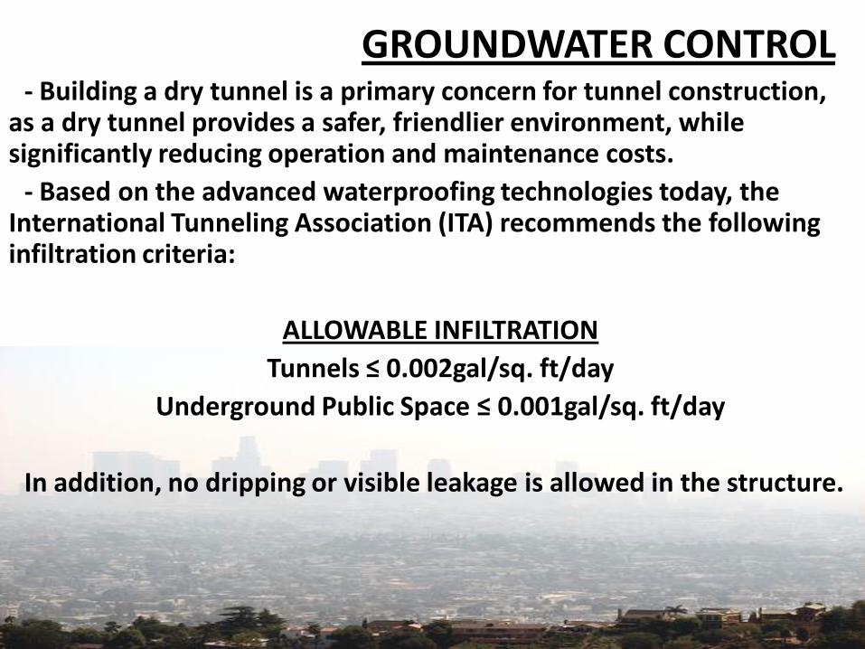
- Building a dry tunnel is a primary concern for tunnel construction, as a dry tunnel provides a safer, friendlier environment, while significantly reducing operation and maintenance costs.
- Based on the advanced waterproofing technologies today, the International Tunneling Association (ITA) recommends the following infiltration criteria:
ALLOWABLE INFILTRATION
Tunnels ≤ 0.002gal/sq. ft/day
Underground Public Space ≤ 0.001gal/sq. ft/day
In addition, no dripping or visible leakage is allowed in the structure.
GROUNDWATER CONTROL

There are two basic types of waterproofing systems: drained (open) and undrained (closed).
Open waterproofing system allows groundwater inflow into the tunnel drainage system. The tunnel vault area is equipped with a waterproofing system that forms an umbrella-like protection that drains seeping water into a prepared drainage system located at the bottom of the tunnel sidewalls and in the tunnel invert. It is usually used in rock tunnels where infiltration rates are usually low.
Closed Waterproofing system extend around the entire tunnel perimeter, and thus exclude water from entering into the tunnel drainage. The linings are thus designed to cater for hydrostatic pressure. It is used in permeable soils where groundwater discharge into the tunnel would be significant, and its discharge would lower the water table and probably cause settlements.
GROUNDWATER CONTROL

INVESTIGATIONSSeveral investigations are required at the preliminary, design
and construction phases of a tunnel project. The processes are highlighted below:
• Collection and Review of Available Information for a general knowledge of the area (Existing Topographical, hydrological, Geological, Geotechnical, Seismic, Environmental, Zoning etc)
• Topographic and Aerial Photographs
• Reconnaissance and Preliminary Surveys
• Water Well Logs
• Flood Insurance Maps
• Hydrographic Surveys
• Utility Surveys (especially in cities)
• Identification of Underground Structures and Obstacles

•Structure Preconstruction Survey•Geologic Mapping•Subsurface Investigations•Test Borings and Sampling•Sampling - Overburden Soils•Sampling – Rock Core•Soil and Rock Identification and Classification•In - situ Tests•Geophysical Tests•Seismic Wave Propagation•Laboratory Tests•Groundwater Investigation•Pumping Tests
TUNNELLING CONSTRUCTION METHODOLOGIES

TUNNELLING CONSTRUCTION METHODOLOGIES
(a) Cut and Cover System.
(b) Pipe Jacking System (Micro Tunneling).
(c) Shield Tunneling (TBM).
(d) New Austrian Tunneling Method (NATM).
(e) Immersed-Tube Tunneling System.

CUT AND COVER METHOD
Sequence of Construction (Stages 1 to 3)

CUT AND COVER METHOD
Sequence of Construction (Stages 4 to 6)

Advantages:
• Economy for shallow depths (4 - 10 m) and for shorter applications.
• Un-sophisticated labor and equipment required.
• Adaptability to different conditions.
• Simple structural & geotechnical analyses required.
• Safe environment (ventilation and fire hazard).
Disadvantages:
• Possible disturbances to existing facilities.
• Practical limitations of depth.
• Unsuitability under buildings or water.
CUT AND COVER METHOD

• Grouting is the process of filling gaps using mortar.
• In Tunnel Construction, gaps in the soil needs to be filled using mortar to prevent the collapse or sinking of the ground and the tunnel.
• The process of soil grouting is shown below:
SOIL GROUTING

Soil Grouting Techniques
Jet Grouting: Soil Replacement Process

Soil Grouting Techniques
Slurry Wall Concept

(b) Pipe Jacking System (Micro Tunneling)
Schematic Representation

23
Preparation ofDriving Shaft
Jacking PipesUsing Hydraulic Jacks
Tunnel Construction
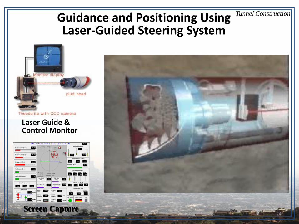
24
Guidance and Positioning UsingLaser-Guided Steering System
Laser Guide &Control Monitor
Screen Capture
Tunnel Construction

25
MTBM Break Through
Extraction of MTBM
Tunnel Construction
26
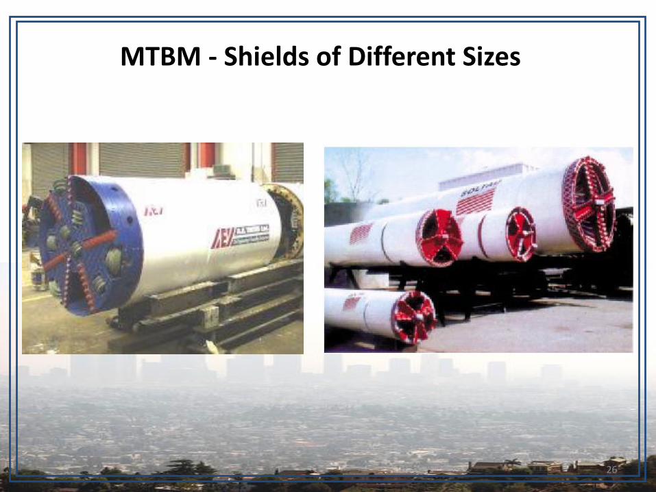
MTBM - Shields of Different Sizes

27
MTBM - Different Shapes of Cutting Heads
Dirt cutter head(clay and silty sand)
Sand shelves
Carbide cutter head(soft to medium hard rock)

28
Pipe Jacking System (Micro Tunneling)
Advantages:• Suitability for almost all types of soil.
• Large depths with unlimited lengths of drive.
• High levels of accuracy and safety.
• Wide choice of pipe and joint materials.
• High construction rates.
• Reduced manpower requirements.
• Reduced environmental disturbance.
Disadvantages:• Sophisticated equipment and highly skilled labor.
• Inability to make rapid changes in line or level.
• Very expensive corrective actions, if required.

29
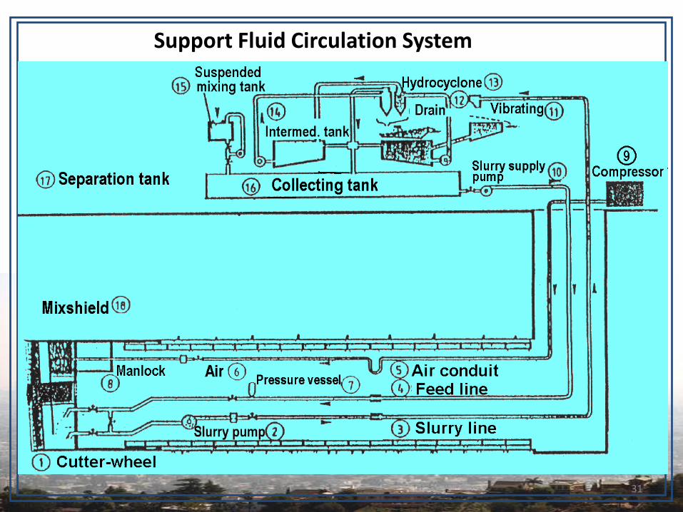
(c) Shield Tunneling (TBM)
Cutter Head Tunnel Tube

31
Support Fluid Circulation System

32
Construction Sequence

33
Shield Tunneling (TBM)
Advantages:• Suitability for almost all types of soil.
• Suitability for wide tunnels (highway, railway, etc.).
• Large depths ( > 10 m), with unlimited lengths of drive.
• Reducing environmental disturbance and utilities diversions.
Disadvantages:• Sophisticated equipment and highly skilled labor.
• Inability to make rapid changes in line or level.
• Very expensive corrective actions, if required.
• Difficult structural and geotechnical analyses reqd.
34
ConstructionSequence
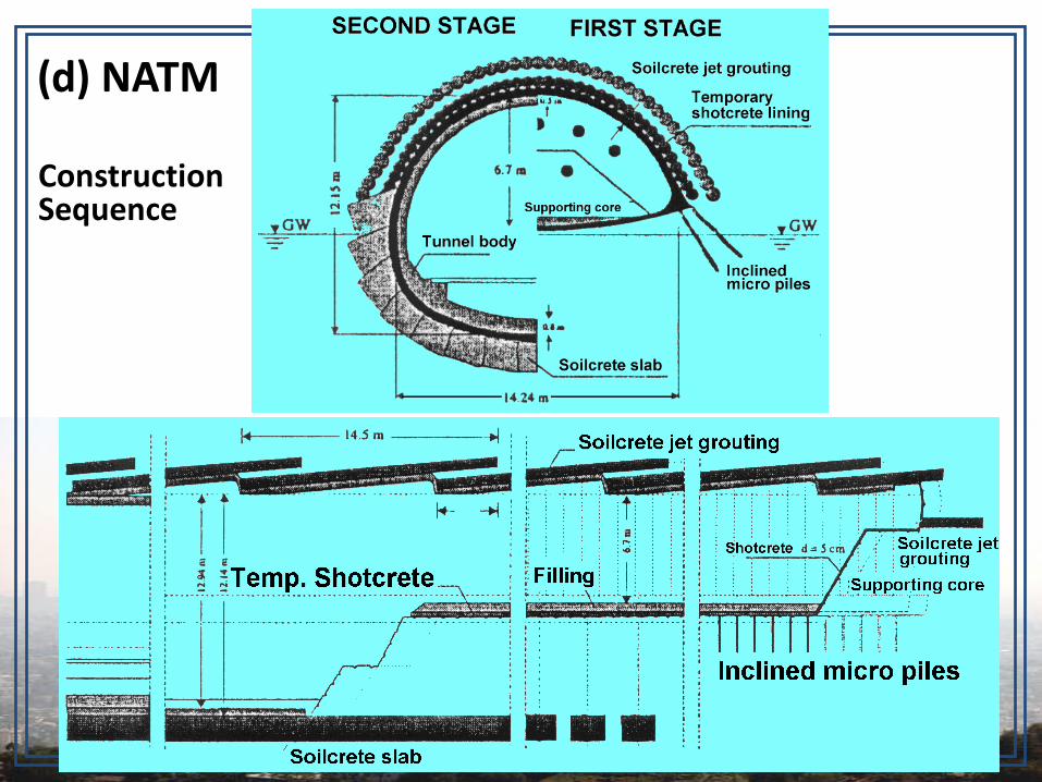
(d) NATM

35
New Austrian Tunneling MethodAdvantages:
• Best alternative for non-circular roadway tunnels.
• Suitability for almost all stable to strong ground types, including rock.
• Suitability for a variety of soil conditions.
• Small thickness of tunnel lining, reducing the amount of excavation.
• Economy and speed of construction.
Disadvantages:• Highly skilled workers and expert engineers.
• Safety measures for shotcrete application.
• Ground water freezing and/or soil strengthening (in case of water-bearing cohesion-less soil).
36
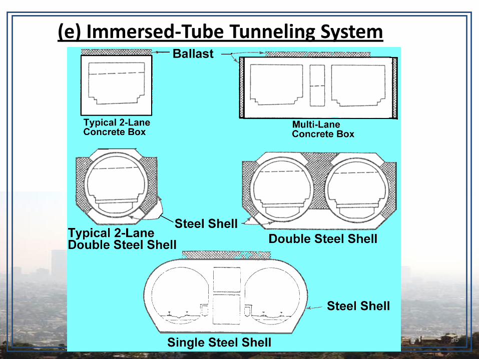
(e) Immersed-Tube Tunneling System

37
(e) Immersed-Tube Tunneling System
Construction Sequence:
1. Dredging the trench in river or sea bottom.
2. Prefabrication of tunnel sections, and sealing ends with bulkheads.
3. Floating the sections to the tunnel trench.
4. Lowering the sections to seabed.
5. Joining the sections together underwater.
6. Removing the temporary bulkheads.
7. Backfilling the trench.
38
Immersed-Tube Tunneling System
Advantages:• Economy (most economical alternative for any type
of underwater tunnel crossing).
• High construction rates (particularly for steel tube tunnels).
• Wide variety of different conditions.
Disadvantages:• Casting basin (for concrete box tunnels).
• Highly skilled and experienced workers.
• Safety measures for underwater construction.

Other Necessary Features
• Lighting
• Aeration and Ventilation

References
• American Association of State Highway & Transportation Officials Technical Committee for Tunnels (T – 20).
• Taylor and Francis Group, Handbook of Highway Engineering, 2006.
• Design Highway Manual, Federal Republic of Nigeria, 2006
• Jean Pierre Pompee, Channels Tunnel Construction.

Thank you