POWER OPTIMIZATION FOR EMBEDDED SYSTEM … Optimization...POWER OPTIMIZATION FOR EMBEDDED SYSTEM...
14
POWER OPTIMIZATION FOR EMBEDDED SYSTEM IDLE TIME IN THE PRESENCE OF PERIODIC INTERRUPT SERVICES Gang Zeng, Hiroyuki Tomiyama, and Hiroaki Takada Graduate School of Information Science, Nagoya University, Furo-cho, Chikusa-ku, Nagoya 464-8603, Japan Abstract: Generally, there are periodic interrupt services in the real-time embedded systems even when the system is in the idle state such as the periodic clock tick interrupts. To minimize the idle power, power management therefore should consider the effect of periodic interrupt services. In this paper, we deal with this problem considering two scenarios. In case the periodic interrupt cannot be disabled, we first model the power consumption and then propose static and dynamic approaches for the optimal frequency selection to save idle power. On the other hand, in case the periodic interrupt can be disabled, we propose an approach to delay the interrupt service until the next task is released so that the processor can stay in low power mode for longer time. The proposed approaches are implemented in a real-time OS and its effectiveness has been validated by theoretical calculations and actually measurements on an embedded processor. Key words: dynamic power management; dynamic voltage/frequency scaling; real-time embedded systems 1. INTRODUCTION Energy consumption has become one of the major concerns in today’s embedded system design especially for battery-powered devices. For the sake of dependability, in real-time systems the utilization of processor is less than 100% even if all tasks run at WCET (worse case execution time). Moreover, workload of each task may vary from time to time, which results in the less average execution time than the WCET. All these factors lead to the system idle state in which there are no tasks needed to be scheduled. It Volume 231, Embedded System Design: Topics, Techniques and Trends, eds. A. Rettberg, Zanella, M., Dömer, R., Gerstlauer, A., Rammig, F., (Boston: Springer), pp. 241–254. Zeng, G., Tomiyama, H., Takada, H, 2007, in IFIP International Federation for Information Processing,
Transcript of POWER OPTIMIZATION FOR EMBEDDED SYSTEM … Optimization...POWER OPTIMIZATION FOR EMBEDDED SYSTEM...

POWER OPTIMIZATION FOR EMBEDDED SYSTEM IDLE TIME IN THE PRESENCE OF PERIODIC INTERRUPT SERVICES
Gang Zeng, Hiroyuki Tomiyama, and Hiroaki Takada Graduate School of Information Science, Nagoya University, Furo-cho, Chikusa-ku, Nagoya 464-8603, Japan
Abstract: Generally, there are periodic interrupt services in the real-time embedded systems even when the system is in the idle state such as the periodic clock tick interrupts. To minimize the idle power, power management therefore should consider the effect of periodic interrupt services. In this paper, we deal with this problem considering two scenarios. In case the periodic interrupt cannot be disabled, we first model the power consumption and then propose static and dynamic approaches for the optimal frequency selection to save idle power. On the other hand, in case the periodic interrupt can be disabled, we propose an approach to delay the interrupt service until the next task is released so that the processor can stay in low power mode for longer time. The proposed approaches are implemented in a real-time OS and its effectiveness has been validated by theoretical calculations and actually measurements on an embedded processor.
Key words: dynamic power management; dynamic voltage/frequency scaling; real-time embedded systems
1. INTRODUCTION
Energy consumption has become one of the major concerns in today’s embedded system design especially for battery-powered devices. For the sake of dependability, in real-time systems the utilization of processor is less than 100% even if all tasks run at WCET (worse case execution time). Moreover, workload of each task may vary from time to time, which results in the less average execution time than the WCET. All these factors lead to the system idle state in which there are no tasks needed to be scheduled. It
Volume 231, Embedded System Design: Topics, Techniques and Trends, eds. A. Rettberg, Zanella, M., Dömer, R., Gerstlauer, A., Rammig, F., (Boston: Springer), pp. 241–254.
Zeng, G., Tomiyama, H., Takada, H, 2007, in IFIP International Federation for Information Processing,

Gang Zeng, Hiroyuki Tomiyama, Hiroaki Takada
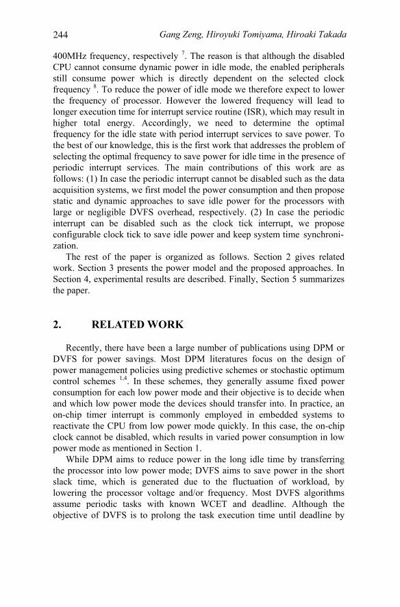
should be noted that even in the idle state, most real-time OS maintains a periodic clock interrupt to synchronize the system and trace the clock events. For example the uc/OS-II, eCOS, and Linux need a 10ms clock interrupt to generate the system clock. Besides the period clock tick, some interrupt-driven embedded systems such as data acquisition systems also need periodic interrupts to activate the CPU from low power mode for data processing. To reduce the power of the idle state, a common approach is to transfer the processor into a low power mode. Generally, a processor can provide multiple low power modes to deal with different system states. To take advantages of these power control mechanisms, dynamic power management (DPM) tries to assign the optimal low power mode according to the predicted duration of the system idle state. As an example, Figure 1 shows the power mode transition graph for two typical embedded processors in high-end and low-end applications, respectively. Two observations can be derived from Fig. 1 as follows: (1) Although different processors may have different names of low power modes, they utilize similar techniques for power control by disabling either CPU clock or both CPU and peripheral clocks. (2) The power mode transitions consume both time and power overhead which are dependent on the specified low power mode and the complexity of processors.
Run Mode
SleepMode Idle Mode
10 us
90 us
160 m
s
10 us
90 us
Prun = 400 mW
Pidle = 50 mWPsleep = 0.16 mW
Normal Mode
StopMode
Wait Mode
10 us
0.21mJ80 u
s 0.4
8 mJ
2 us2 us
Pnormal = 7 - 30 mW(1.25MHz - 20MHz)
Pwait = 3.6 - 3.9 mW(1.25MHz - 20MHz)Pstop = 0.03 mW
(a) SA-1100 (b) M16C
Figure 1. Power mode transition for (a) Intel’s StrongARM SA-1100 processor 1 (b) Renesas’s M16C processor.
While the SA-1100 with integrated 32-bit RISC core targets for high performance low power application, the M16C 11 with integrated 16-bit CISC core, on-chip ROM and RAM aims at low-end and low power application. The SA-1100 processor provides three operation modes with different power consumption levels, i.e., Run, Idle, and Sleep modes. The Run mode is the normal operating mode with full functionalities and high power consumption. In contrast, the Idle and Sleep modes are low power modes with stopped CPU clock. Idle mode stops the CPU core clock but enables all peripherals clock thus on- or off-chip interrupt service requests
242

Power Optimization for Embedded System Idle Time can quickly reactivate the CPU. On the other hand, Sleep mode stops both CPU and peripherals clock thus only hardware reset or special event can wakeup the CPU, which requires long transition time whenever entering or exiting the Sleep mode. Similarly, the M16C also provides three power modes which have similar functionalities to that of the SA-1100 but with different names. However, the time and power overhead of M16C for power mode transition is much less than that of SA-1100. This small transition overhead of M16C is benefited from its simple and single-chip architecture. Actually, only one instruction is needed to transfer the processor into wait mode.
Although the Sleep mode of SA-1100 has the lowest power consumption, it is not suitable for the application considered in this paper. The reasons are that (1) the transition time overhead for returning to run mode is too large to be used in the application with short period of interrupt services; (2) the normal interrupt service requests related to on-chip clock cannot work properly in the Sleep mode. Therefore, the feasible low power mode that can be used for power management of idle time with periodic interrupt services is the idle mode.
In addition to DPM, another effective technique for power saving is dynamic voltage/frequency scaling (DVFS), because the power consumption of CMOS circuits is proportional to its clock frequency and its voltage square. The DVFS tries to change the clock frequency and its corresponding supply voltage dynamically to the lowest possible level while meeting the task’s deadline constraint. Commonly, the voltage and frequency scaling are accomplished by controlling a DC-DC converter and PLL (phase lock loop) circuit, respectively. Although many high-end processors have equipped with the DVFS capabilities, few low-end processors can dynamically change their supply voltages such as the M16C. In contrast, most low-end processors can still change its clock frequency by setting the divider registers. As a result, the time overhead for frequency change is much less for a simple processor using divider register than a complex processor using PLL. For example, the M16C requires negligible time for frequency change. In contrast, many commercial high-performance processors require the transition time ranging from 189us to 3.3ms for voltage and frequency scaling 10. For simplicity, we refer to DVFS in the following whenever voltage and frequency or only frequency is changed during execution.
The motivation for this work stems from the fact that the power consumption of processor in idle mode is not fixed but dependent on the selected clock frequency before entering the idle mode 7. In general, the higher frequency, the more power is consumed in idle mode. For example, the PXA225 processor (an upgraded product of SA-1100 series) consumes 45mW-121mW power in idle mode which corresponds to 100MHz -
243
Gang Zeng, Hiroyuki Tomiyama, Hiroaki Takada
400MHz frequency, respectively 7. The reason is that although the disabled CPU cannot consume dynamic power in idle mode, the enabled peripherals still consume power which is directly dependent on the selected clock frequency 8. To reduce the power of idle mode we therefore expect to lower the frequency of processor. However the lowered frequency will lead to longer execution time for interrupt service routine (ISR), which may result in higher total energy. Accordingly, we need to determine the optimal frequency for the idle state with period interrupt services to save power. To the best of our knowledge, this is the first work that addresses the problem of selecting the optimal frequency to save power for idle time in the presence of periodic interrupt services. The main contributions of this work are as follows: (1) In case the periodic interrupt cannot be disabled such as the data acquisition systems, we first model the power consumption and then propose static and dynamic approaches to save idle power for the processors with large or negligible DVFS overhead, respectively. (2) In case the periodic interrupt can be disabled such as the clock tick interrupt, we propose
The rest of the paper is organized as follows. Section 2 gives related work. Section 3 presents the power model and the proposed approaches. In Section 4, experimental results are described. Finally, Section 5 summarizes the paper.
2. RELATED WORK
Recently, there have been a large number of publications using DPM or DVFS for power savings. Most DPM literatures focus on the design of power management policies using predictive schemes or stochastic optimum control schemes 1,4. In these schemes, they generally assume fixed power consumption for each low power mode and their objective is to decide when and which low power mode the devices should transfer into. In practice, an on-chip timer interrupt is commonly employed in embedded systems to reactivate the CPU from low power mode quickly. In this case, the on-chip clock cannot be disabled, which results in varied power consumption in low power mode as mentioned in Section 1.
While DPM aims to reduce power in the long idle time by transferring the processor into low power mode; DVFS aims to save power in the short slack time, which is generated due to the fluctuation of workload, by lowering the processor voltage and/or frequency. Most DVFS algorithms assume periodic tasks with known WCET and deadline. Although the objective of DVFS is to prolong the task execution time until deadline by
244
configurable clock tick to save idle power and keep system time synchroni- zation.
Power Optimization for Embedded System Idle Time lowering the CPU’s voltage and frequency, the slack time cannot be reclaimed completely. This is because the generated slack time can only be reclaimed when there are ready tasks that can be scheduled immediately. Moreover, the discrete frequency levels makes DVFS cannot utilize the generated slack time completely. All these factors result in idle time even in the DVFS enabled systems. However, most DVFS literatures ignore the idle time process by simply assuming a low power mode with zero power 2,3 or fixed power consumption 10 in idle time. As shown in Section 1, even in low power mode, the power consumption is neither zero nor fixed value, which is dependent on the on-chip clock frequency. Moreover the required time for power mode transition may be too long to be applicable for short idle time, which results in no power reduction in this case.
Recently, a variable scheduling timeouts method is proposed for power savings in Linux systems by eliminating the useless tick interrupts during system idle time 9. However a problem needed to be considered in real-time systems is how to keep the system clock synchronization caused by tick timer reprogramming.
3. POWER MODEL AND APPROACHES
For general low power embedded processors, we assume that the
We deal with the power saving problem of idle state in two different cases. While in case one the periodic interrupt cannot be disabled such as the data acquisition system, in case two the interrupt can be disabled for a specified duration such as the clock tick interrupt.
3.1 Case one: the periodic interrupt cannot be disabled
Before modeling the power consumption of idle state with periodic interrupt services, we give the following notations. • M: selected system speed, i.e., 1/M full speed • Tp (us): period of interrupt service
245
processor can provide multiple low power modes and alterable voltage/ frequency for power control. To simply the calculation, we assume that the time and power overhead for power mode transition and voltage/ frequency scaling are fixed. As discussed earlier, for power managementof idle state with periodic interrupt services, only the low power modewith enabled peripherals clock is considered. We assume that an idle taskis employed to implement the proposed power management in RTOS. Theidle task is scheduled to run when system enters the idle state in wnich notasks need to be scheduled in the ready queue.

Gang Zeng, Hiroyuki Tomiyama, Hiroaki Takada
• Th (us): execution time of interrupt service routine at full speed • Ts (us): execution time for low power mode setting in idle task at full
speed • Tp (us): time overhead for power mode transition • Ip (mA): average current during power mode transition • Tv (us): time overhead for dynamic voltage/frequency scaling • Iv (mA): average current during voltage/frequency scaling • Irm (mA): the run mode average current at 1/M full speed • Iim (mA): the idle mode average current at 1/M full speed • Vm (V): the corresponding voltage for 1/M full speed setting
Considering the fact that different scale processors may have different DVFS overhead as discussed in Section 1, we propose static and dynamic approaches for processors with large or negligible DVFS overhead, respectively.
Figure 2. Processing procedure for idle state power management.
If the processor has large DVFS time overhead, a static approach is adopted, i.e., only once DVFS setting at the beginning of idle state for any
time to enter idle state, it first sets the optimal speed for power savings and then enters low power mode. Otherwise, it only sets and enters the low power mode and without any speed change when the idle task is reactivated from low power mode by interrupt. The above processing procedure for idle
procedure, the average current and power of idle state with periodic interrupt services can be calculated by the following equations:
p
ppimpshprmshidle T
ITITMTTTIMTTI
⋅+⋅−⋅+−+⋅⋅+=
))(()( (1)
midleidle VIPower ⋅= (2)
246
continuous idle time. Specifically, the program in idle task takes corres- ponding actions according to the current system state, if it is the first
power management is illustrated in Fig. 2. Based on the above notations and

Power Optimization for Embedded System Idle Time
Therefore, if the period of interrupt and the execution time for power mode setting are known and fixed, time and power overhead for power mode transition, the average current with different speed settings for run and idle mode can be obtained from processor data manual or actual measurements, the average current of idle state will be a function of the selected speed M and the execution time of interrupt service Th. According to this function, the power optimization problem can be formulated as: for a specified processor and application with known Th, Ts, Tp, Ip, Irm, and Iim, finds the optimal M such that the average idle current is minimal. Because the relation between Iidle and M is linear, and the selectable speeds are limited, we can calculate all curves of Iidle-Th with all possible speed selections, and then the one that has the minimal average current will be the optimal speed setting.
If the processor has negligible DVFS time overhead, a dynamic approach may save more power at the expense of two DVFS settings for each interrupt process. The procedure is that the full speed is set at the beginning of each interrupt service, and the slowest speed is set before entering the low power mode each time. Its objective is to save more power by keeping the processor in low power mode with the minimal power consumption for longer time. In this case, the average idle current can be calculated by the following equation:
p
vvppinvtshprshidle T
ITITITTTTTITTI
⋅+⋅+⋅−−+−+⋅+=
2)2)(()( 1 (3)
where Ir1 represents the current of full speed running, and Iin represents the current of the slowest speed in idle mode. Note that this approach is not realistic for some complex processors with large DVFS overhead. For example, Intel’s PXA225 requires 500us for each DVFS scaling 7; obviously in this case, the dynamic approach is not applicable for the interrupt service with 1 ms period.
3.2 Case two: the periodic interrupt can be disabled for a specified duration
We assume periodic tasks with known WCET and deadline in embedded systems, and we only discuss how to disable clock tick interrupt by using a configurable clock tick in order to save more power during idle state. Under the above assumptions, whenever system detects the beginning of an idle state, it also knows the nearest releasing time of a periodic task. In this case, the duration of the idle state is known, we therefore can disable the clock tick for this known idle time and transfer the processor into low power mode to save power. Note that this approach is different from general DPM in that
247
Gang Zeng, Hiroyuki Tomiyama, Hiroaki Takada
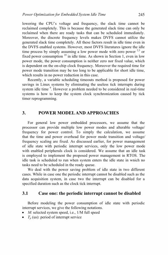
while general DPM makes decision for power mode transition based on the predicted duration of idle time; this approach is with known duration of idle time. Therefore the decision for power mode transition in this approach is straightforward.
Tick Interrupt Disabled
Counted Clock
Timer 1: Clock Tick Timer
Timer 2: Wake up Timer
Timer 1 overflow signal
Wake up InterruptEnabled
Timer setting procedure:When system enters the idle state
1. Set the count value of Timer 2 as the known duration of idle state2. Disable Timer 1 interrupt3. Start Timer 24. Enter low power mode
When system returns to normal mode by Timer 2 interrupt1. Update the system tick by adding the loss clock ticks to current clock ticks2. STOP Timer 23. Enable Timer 1 interrupt
(a) (b)
Figure 3. Configurable clock tick and timer setting procedure.
When the clock tick interrupt is disabled during idle state, a problem that should be considered is how to trace the original clock tick to keep system
used to count the lost ticks during idle time when the tick interrupt is disabled. Because the original tick timer is never stopped and restarted except disabling its interrupt requests, the system time synchronization can be guaranteed easily. However, this approach is hardware-dependent since a wire connection between the output of timer 1 and the input of timer 2 is
wakeup interrupt prior to the release of next task should be set to the known
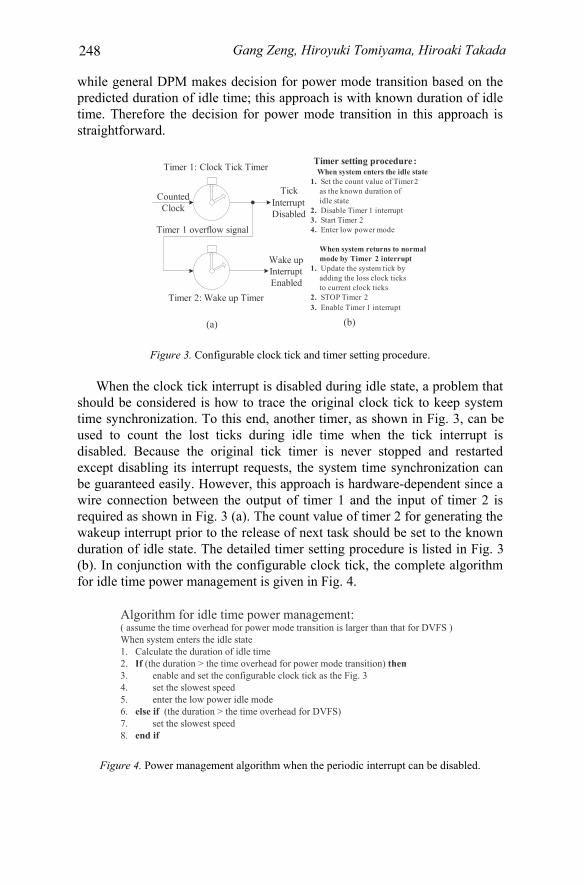
(b). In conjunction with the configurable clock tick, the complete algorithm
Algorithm for idle time power management:( assume the time overhead for power mode transition is larger than that for DVFS )When system enters the idle state1. Calculate the duration of idle time2. If (the duration > the time overhead for power mode transition) then3. enable and set the configurable clock tick as the Fig. 34. set the slowest speed5. enter the low power idle mode6. else if (the duration > the time overhead for DVFS)7. set the slowest speed8. end if
Figure 4. Power management algorithm when the periodic interrupt can be disabled.
248
time synchronization. To this end, another timer, as shown in Fig. 3, can be
required as shown in Fig. 3 (a). The count value of timer 2 for generating the
duration of idle state. The detailed timer setting procedure is listed in Fig. 3
for idle time power management is given in Fig. 4.

Power Optimization for Embedded System Idle Time 4. EVALUATION AND EXPERIMENTAL RESULTS
4.1 Experiment setup and measurement environment
To validate and evaluate the proposed approach, we select the OAKS16-mini board with a M16C (M30262F8GP) embedded processor to implement the approach. Although the processor cannot change its supply voltage, it provides three power modes and can quickly change its clock frequencies by setting the divider registers. We measure the processor current by inserting a digital multimeter between the power supply and the power pin of the processor. An oscilloscope is utilized to observe the voltage waveform of the shunt resistor which is inserted between the power supply and the power pin of the processor. The time and power overhead for power mode transition are estimated by using the captured voltage waveform. Note that the above experiments are performed separately so that the current measurements are carried out with removed shunt resistor. The measured power results and estimated power mode transition overhead are given in Fig.1.
Our approach has been implemented in a RTOS called TOPPERS/JSP kernel 5 which is an open source RTOS in consistent with the ITRON 6 standard. The TOPPERS RTOS targets for real-time applications with limited resource requirement. A configurable clock tick is implemented in OS with default 1 ms interrupt period. The normal execution time of the timer handler for system time updating is about 12 us at 20MHz.
4.2 Evaluation of the proposed approach when the periodic interrupts cannot be disabled
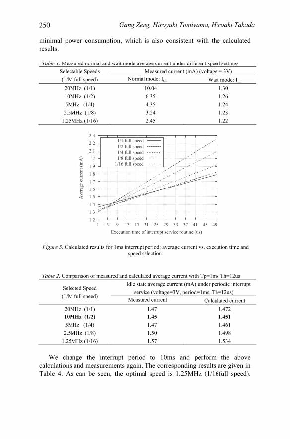
Table. 1 summaries the measured normal and wait mode average current under different speed settings. Note that all these measurements are performed by executing a busy loop and the results for wait mode is measured with clock enable but without any interrupt services.
Based on these measured parameters, and Eq. (1), we can obtain the
figure, it is clear that the optimal speed selection for minimal power consumption is determined by the execution time of ISR. As for the 12us interrupt service in this experiment, the optimal speed is 10MHz (1/2 full speed). The calculated and measured results are denoted in Table 2, respectively, where the minimal measured current is consistent with the theoretical calculated results. We modify the ISR and reduce the execution time of ISR to 7us, and perform the above experiments again. As can be seen from the results given in Table 3, 5MHz (1/4 full speed) can achieve the
249
following current vs. execution time and speed curves in Fig. 5. From this
Gang Zeng, Hiroyuki Tomiyama, Hiroaki Takada
minimal power consumption, which is also consistent with the calculated results.
Table 1. Measured normal and wait mode average current under different speed settings Measured current (mA) (voltage = 3V) Selectable Speeds
(1/M full speed) Normal mode: Irm Wait mode: Iim 20MHz (1/1) 10.04 1.30 10MHz (1/2) 6.35 1.26 5MHz (1/4) 4.35 1.24 2.5MHz (1/8) 3.24 1.23
1.25MHz (1/16) 2.45 1.22
1.21.31.41.51.61.71.81.9
22.12.22.3
1 5 9 13 17 21 25 29 33 37 41 45 49
Ave
rage
cur
rent
(mA
)
Execution time of interrupt service routine (us)
1/1 full speed1/2 full speed1/4 full speed1/8 full speed
1/16 full speed
Figure 5. Calculated results for 1ms interrupt period: average current vs. execution time and speed selection.
Table 2. Comparison of measured and calculated average current with Tp=1ms Th=12us Idle state average current (mA) under periodic interrupt
service (voltage=3V, period=1ms, Th=12us) Selected Speed (1/M full speed) Measured current Calculated current
20MHz (1/1) 1.47 1.472 10MHz (1/2) 1.45 1.451 5MHz (1/4) 1.47 1.461 2.5MHz (1/8) 1.50 1.498
1.25MHz (1/16) 1.57 1.534
We change the interrupt period to 10ms and perform the above calculations and measurements again. The corresponding results are given in Table 4. As can be seen, the optimal speed is 1.25MHz (1/16full speed).
250

Power Optimization for Embedded System Idle Time When we further prolong the interrupt period to 100ms, the results show that the slowest speed will achieve the minimal power consumption in spite of the variation of execution time. The reason is that for longer interrupt period, most of time the processor stays in low power mode, thus, the average power is dominated by the power of long idle state but not the power of short execution state.
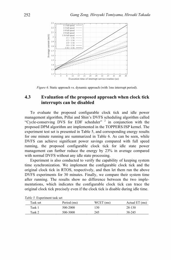
Experiments are also conducted to validate the proposed dynamic approach especially for the M16C with negligible DVFS overhead. In these experiments, the varied speeds are set at the beginning of ISR, and the slowest speed (1/16 full speed) is set in the idle task before entering the low power mode. The calculated results using Eq. (3) and assuming negligible
dynamic approaches are shown, respectively. As can be seen, the full speed setting for ISR plus the slowest speed setting (1/16) for low power mode outperforms other speed combinations in dynamic approach, and all speed settings in static approach. Meanwhile, the actually measured result for this case shows average current 1.39 mA which is the minimal current compared with the measured results for static approach in Table 2. The results indicate that the dynamic approach can further reduce the average power by 4.3% than the optimal static approach, and achieves the maximal 11% reduction in average power than the approach without frequency selection for idle state.
Table 3. Comparison of measured and calculated average current with Tp=1ms Th=7us Idle state average current (mA) under periodic interrupt
service (voltage = 3V, period = 1ms, Th = 7us) Selected Speed (1/M full speed) Measured current Calculated current
20MHz (1/1) 1.40 1.419 10MHz (1/2) 1.38 1.389 5MHz (1/4) 1.37 1.385 2.5MHz (1/8) 1.38 1.401
1.25MHz (1/16) 1.42 1.416
Table 4. Comparison of measured and calculated average current with Tp=10ms Th=12us Idle state average current (mA) under periodic interrupt
service (voltage=3V, period=10ms, Th=12us) Selected Speed (1/M full speed) Measured current Calculated current
20MHz (1/1) 1.32 1.317 10MHz (1/2) 1.28 1.279 5MHz (1/4) 1.25 1.262 2.5MHz (1/8) 1.24 1.256
1.25MHz (1/16) 1.24 1.251
251
DVFS overhead are depicted in Fig. 6 where the curves for static and
Gang Zeng, Hiroyuki Tomiyama, Hiroaki Takada
1.2
1.3
1.4
1.5
1.6
1.7
1.8
1.9
2
2.1
2.2
2.3
1 5 9 13 17 21 25 29 33 37 41 45 49
Ave
rage
cur
rent
(mA
)
Execution time of interrupt service routine (us)
1/1 full speed1/2 full speed1/4 full speed1/8 full speed
1/16 full speed1/1 + 1/161/2 + 1/161/4 + 1/161/8 + 1/16
1/16 + 1/16
Figure 6. Static approach vs. dynamic approach (with 1ms interrupt period).
4.3 Evaluation of the proposed approach when clock tick interrupts can be disabled
To evaluate the proposed configurable clock tick and idle power management algorithm, Pillai and Shin’s DVFS scheduling algorithm called “Cycle-conserving DVS for EDF scheduler” 2 in conjunction with the proposed DPM algorithm are implemented in the TOPPERS/JSP kernel. The experiment test set is presented in Table 5, and corresponding energy results for one minute running are summarized in Table 6. As can be seen, while DVFS can achieve significant power savings compared with full speed running, the proposed configurable clock tick for idle state power management can further reduce the energy by 23% in average compared with normal DVFS without any idle state processing.
Experiment is also conducted to verify the capability of keeping system time synchronization. We implement the configurable clock tick and the original clock tick in RTOS, respectively, and then let them run the above DVFS experiments for 30 minutes. Finally, we compare their system time
original clock tick precisely even if the clock tick is disable during idle time.
Table 5. Experiment task set Task set Period (ms) WCET (ms) Actual ET (ms) Task 1 500-2000 130 28-130 Task 2 500-3000 245 38-245
252
after running. The results show no difference between the two imple- mentations, which indicates the configurable clock tick can trace the

Power Optimization for Embedded System Idle Time Table 6. Evaluation of power savings for combined DVFS and power management of idle state
Dynamic EDF DVFS with different idle state
process
P1: 500 ms P2: 500 ms
P1: 500 ms P2: 900 ms
P1: 1000 ms P2: 1500 ms
P1: 2000 ms P2: 3000 ms
No DVFS (full speed)
TE: 1807 mJ NR: 1
TE: 1807 mJ NR: 1
TE: 1807 mJ NR: 1
TE: 1807 mJ NR: 1
DVFS without idle state process
TE: 1594 mJ NR: 0.88
TE: 1288 mJ NR: 0.71
TE: 897 mJ NR: 0.50
TE: 468 mJ NR: 0.26
DVFS setting the lowest speed and entering wait
mode
TE: 944 mJ NR: 0.52
TE: 773 mJ NR: 0.43
TE: 553 mJ NR: 0.31
TE: 282 mJ NR: 0.16
Note: P: task period (ms); TE: Total Energy (mJ); NR: Normalized result
5. CONCLUSION
Even in a DVFS enabled embedded system, there must exist idle time. Moreover, a periodic interrupt services may be required in the system idle time. As a common approach, the processor can be transferred into the low power mode during idle time, its power consumption however is neither zero nor fixed which is dependent on the selected clock frequency. In this work we present different approaches for idle time power management in the presence of periodic interrupt services. In case the periodic interrupt cannot be disabled, we model the power consumption and propose static and dynamic methods to achieve minimal power consumption for the processors with large or negligible DVFS overhead, respectively. In case the periodic interrupt can be disabled such as the periodic clock tick interrupt, we proposed a configurable clock tick to save power by keeping the processor in low power mode for longer time. We implement the proposed approaches in a RTOS and a frequency scaleable embedded processor. The measured results show that the maximal 11% power can be reduced in the first case, and average 23% power can be further reduced in the second case compared with DVFS without any idle processing.
ACKNOWLEDGMENTS
This work is supported by the Core Research for Evolutional Science and Technology (CREST) project from Japan Science and Technology Agency.
253
Gang Zeng, Hiroyuki Tomiyama, Hiroaki Takada
REFERENCES
1. L. Benini, A. Bogliolo, and G. D. Micheli, A survey of design techniques for system-level dynamic power management, IEEE Trans. on Very Large Scale Integration Systems
2. P. Pillai and K. G. Shin, Real-time dynamic voltage scaling for low-power embedded operating systems, Proc. ACM Symposium Operating Systems Principles, pp.89-102, 2001.
3. W. Kim, D. Shin, H. Yun, J. Kim, and S. L. Min, Performance comparison of dynamic voltage scaling algorithms for hard real-time systems, Proc. IEEE Real-Time and
4. Z. Ren, B. H. Krogh, and R. Marculescu, Hierarchical adaptive dynamic power management, IEEE Trans. on Computers, Vol. 54, No. 4, pp. 409-420, April 2005.
5. TOPPERS Project; http://www.toppers.jp/ 6. ITRON Project; http://www.sakamura-lab.org /TRON/ITRON/ 7. Intel, Application Note, PXA255 and PXA26x applications processors power
consumption during power-up, sleep, and idle, April, 2003. 8. Texas Instruments, Application Report, SPRA164, Calculation of TMS320LC54x power
dissipation, June 1997. 9. Variable scheduling timeouts (VST) project page; http://tree.celinuxforum.org/
CelfPubWiki/VariableSchedulingTimeouts 10. D. Shin and J. Kim, Intra-task voltage scheduling on DVS-enabled hard real-time
systems, IEEE Trans. Computer-Aided Design of Integrated Circuits and Systems,
11. Renesas Corp; http://www.renesas.com/fmwk.jsp?cnt=m16c_family_landing.jsp&fp= /products/ mpumcu/m16c_family/
254
(VLSI), Vol. 8, No. 3, pp. 299-316, June 2000.
Embedded Technology and Applications Symposium (RTAS), pp. 219-228, 2002.
Vol. 24, No. 10, pp. 1530-1549, Oct. 2005.