Power Modeling and Power Management Framework Dexin Li December 2002.
26
Power Modeling and Power Management Framework Dexin Li December 2002
-
date post
21-Dec-2015 -
Category
Documents
-
view
221 -
download
0
Transcript of Power Modeling and Power Management Framework Dexin Li December 2002.
Power Modeling and Power Management Framework
Dexin Li
December 2002
Outline
• Background
• Power management architecture
• Component-level power modeling
• System-level power simulation
• Energy optimization
• Preliminary results

Background
• Challenges on power management in complex embedded systems– Interaction and cooperation among multiple components – Existence of inter-component dependencies– Complicated local mode transitions for a global mode change– High cost for a global mode change
• Scope of the work– Purpose a software architecture dealing with power management
complexity – Model components and component modes with dependency– Generate feasible sequence of mode transitions– Optimize the energy for the cost of mode changes

Power Management Architecture
• Separation of policy-maker and component details– Modular, retargetable, – Lessen the burden of policy-maker
• Hierarchical component model– Capable of handling complex systems
• Modeling of inter-component dependency– Enabling complicated mode transition optimization
• Online or offline power simulation– Helpful in obtaining feasible mode transitions and
optimizing system energy
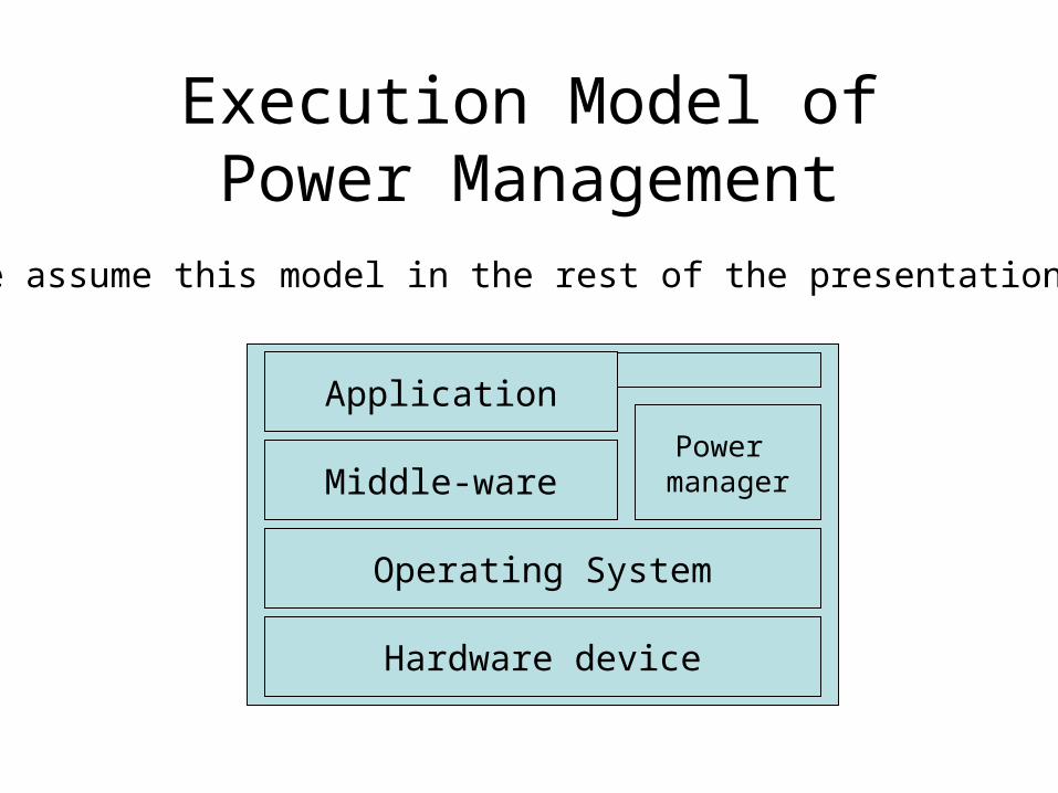
Execution Model of Power Management
Hardware device
Operating System
Middle-ware
Application
Power manager
We assume this model in the rest of the presentation.
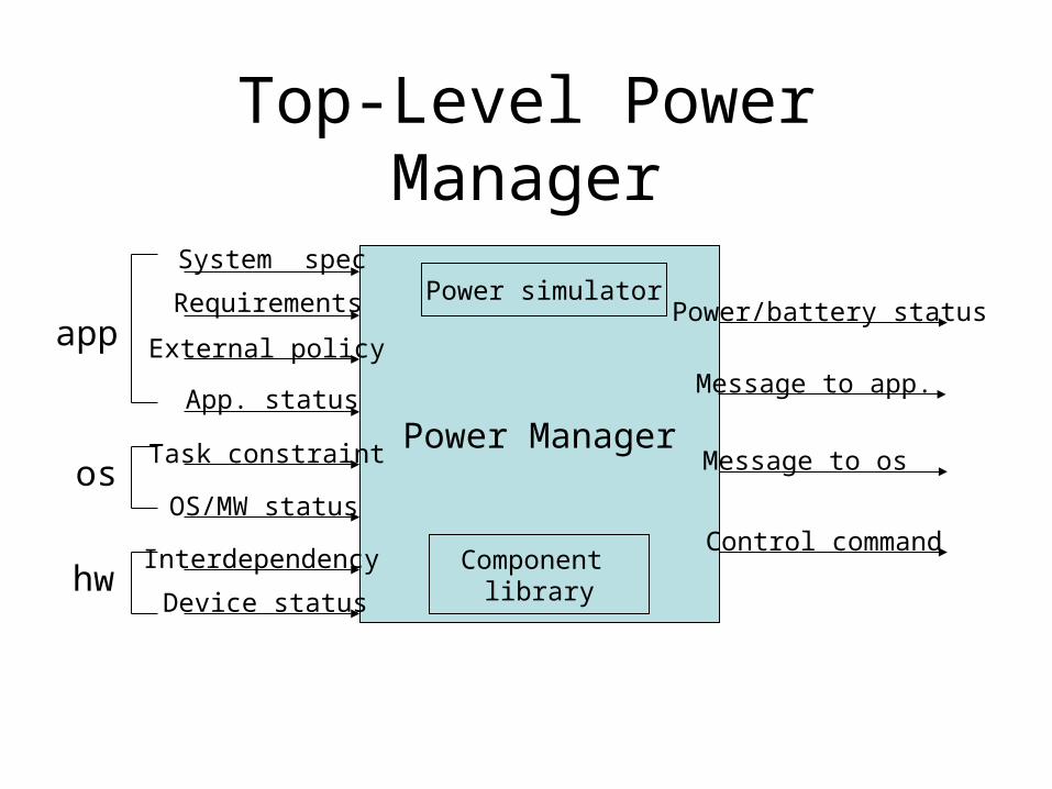
Top-Level Power Manager
Power Manager
Requirements
Device status
OS/MW status
System spec
Component library
Power simulator
External policy
App. status
Interdependency
Task constraint
Power/battery status
Control command
app
os
hw
Message to app.
Message to os
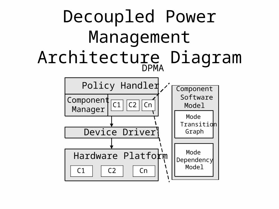
Decoupled Power Management Architecture Diagram
Policy Handler
C1 C2 Cn
Device Driver
C1 C2 Cn
Hardware Platform
ModeTransition
Graph
ModeDependency
Model
DPMA
ComponentSoftware
ModelComponent
Manager

Policy Handler
• Responsibilities– monitor system status– Make system-level power management policies– Send mode change commands
• System interaction – Accept service requests from applications– Accept system requirement or environment input from
middle-ware– Obtain system status from middle-ware or OS– Send mode change commands to Component Manager
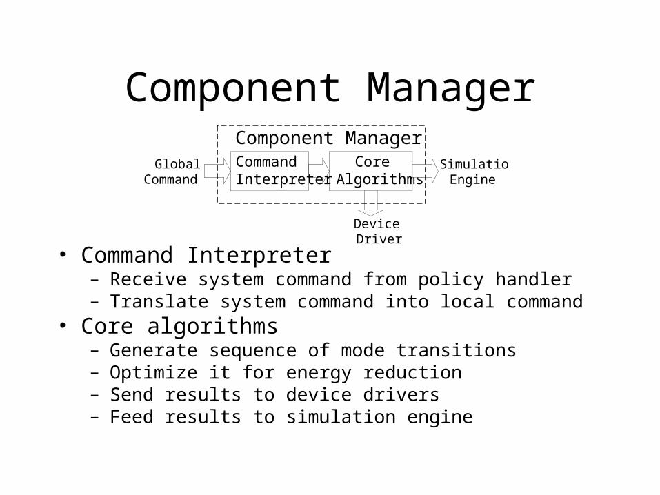
Component Manager
• Command Interpreter– Receive system command from policy handler– Translate system command into local command
• Core algorithms– Generate sequence of mode transitions– Optimize it for energy reduction– Send results to device drivers– Feed results to simulation engine
CommandInterpreter
CoreAlgorithms
GlobalCommand
DeviceDriver
SimulationEngine
Component Manager
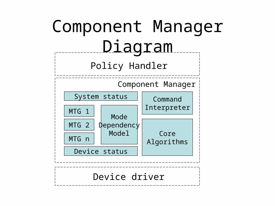
Component Manager Diagram
MTG 1
MTG 2
MTG n
ModeDependency
Model
Device status
System status CommandInterpreter
CoreAlgorithms
Policy Handler
Device driver
Component Manager

Component Modeling Example: Power Amplifier
Device status
System status
Command Interpreter
All-pair-shortest-path Algo.(Floyd-Warshall)
Component manager for PA
off sb
tx
rxf1: fsm_lb
off sb
tx
rxf2: fsm_hb
off on
f3: temp_lb
off on
f4: temp_hb
F1.sb->f2.offF1.tx->f2.offF1.rx->f2.offF2.sb->f1.offF2.tx->f1.offF2.rx->f1.offF1.sb->f3.onF1.tx->f3.onF1.rx->f3.onF2.sb->f4.onF2.tx->f4.onF2.rx->f4.on
Dependency model

Component Manager Example: Power Amplifier
off sb
tx
rxf1: fsm_lb
off sb
tx
rxf2: fsm_hb
Current state: low band transmit
System command: change to high band receive
State transition sequence:f1.tx -> f1.sb -> f1.offf2.off -> f2.sb -> f2.rxf4.off -> f4.on
off on
f4: temp_hb
Optimized for energy reduction:f1.tx -> f1.sb -> f1.offf4.off -> f4.onf2.off -> f2.sb -> f2.rx
Energy:3.88J
Energy:1.88J

System-level Mode Simulation
• Responsibility– Receive sequence of mode transitions – Simulate mode transitions– Parallelize possible mode transitions– Obtain time and energy information– Send the information back to Policy Handler
• Requirement– Detailed timing information for synchronization– Hierarchical component management– Parallelism among different components– Interface to other power management units
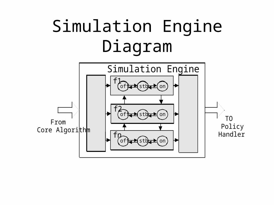
Simulation Engine Diagram
Controller
Monitor
Simulation Engine
off stb onf1
off stb on
off stb on
f2
fn
FromCore Algorithm
TOPolicy
Handler

Energy Optimization
• Objective– Optimize energy consumption for mode changes
• Techniques– Shortest-path algorithm to optimize for one mode
change on one component
– Topological sorting to power up high power component as late as possible
– Mode simulation to parallelize certain mode changes
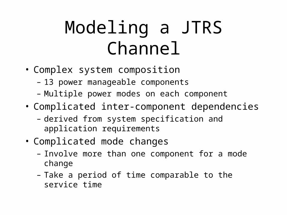
Modeling a JTRS Channel
• Complex system composition– 13 power manageable components
– Multiple power modes on each component
• Complicated inter-component dependencies – derived from system specification and application
requirements
• Complicated mode changes– Involve more than one component for a mode change
– Take a period of time comparable to the service time

Experimental Results
• Test cases:– Case 1: all power-up– Case 2: two modes: on and off– Case 3: 5 system modes without
our model– Case 4: 5 system modes with our
modes
• Results:– Saves 50%-80% energy when
service time is comparable to overhead time
– Saves 20%+ energy when service time is 1000x larger than overhead time

Conclusion
• A new software architecture supporting efficient power management in complex systems
• Component power model enabling power management in complex systems with dependency
• Multiple optimization techniques reducing energy cost for global mode changes
• System-level simulation providing optimized component-level details to global policy-maker

End Slide

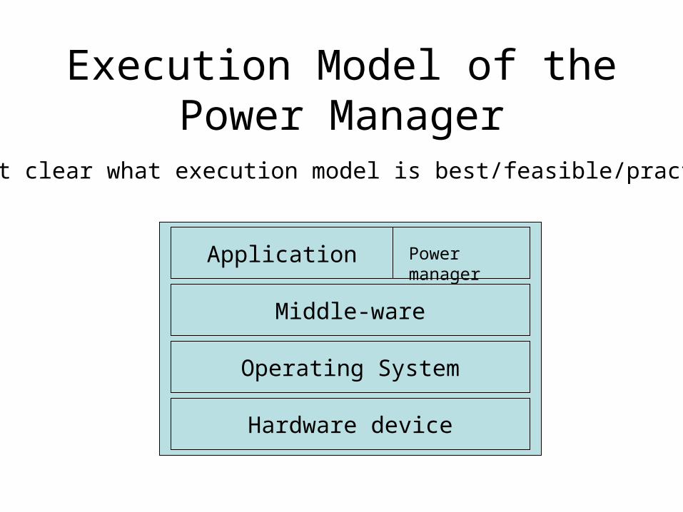
Execution Model of the Power Manager
Not clear what execution model is best/feasible/practical…
Hardware device
Operating System
Middle-ware
Application
Power manager

Device Broker
MTG 1
MTG 2
MTG n
ModeDependency
Model
Device status
System status Commandreceiver/
interpreter
Broker core
System power manager
Device driver

Mode Transition Graph
off stb
tx
rx

Execution Model of the Power Manager
Not clear what execution model is best/feasible/practical...
Hardware device
Operating System
Middle-ware
Application
Power manager

Execution Model of the Power Manager
Not clear what execution model is best/feasible/practical…
Hardware device
Operating System
Middle-ware
Application
Power manager
Execution Model of the Power Manager
Not clear what execution model is best/feasible/practical…
Hardware device
Operating System
Middle-ware
Application Power manager

More Detailed Power Manager Composition
Power Manager (core)Component
librarySimulation
Engine
Sys. specificationApp. Requirements
App/task ConstraintsPower management policy
Device driver
Device model
Device broker I
Device status
Device driver
Device model
Device broker II
Device status
Sys/app status