Power Metal Strip® Resistors - Vishay | Login
65
POWER METAL STRIP ® RESISTORS VISHAY Notes: 1. To navigate: a) Click on the Vishay logo on any datasheet to go to the Contents page for that section. Click on the Vishay logo on any Contents page to go to the main Table of Contents page. b) Click on the products within the Table of Contents to go directly to the datasheet. c) Use the scroll or page up/page down functions. d) Use the Adobe ® Acrobat ® page function in the browser bar. 2. To search the text of the catalog use the Adobe ® Acrobat ® search function. VSE-DB0089-0804 INTERACTIVE VISHAY INTERTECHNOLOGY, INC. data book Discrete Semiconductors and Passive Components One of the World’s Largest Manufacturers of
Transcript of Power Metal Strip® Resistors - Vishay | Login

POWER METAL STRIP® RESISTORS vishay
Notes:1. To navigate: a) Click on the vishay logo on any datasheet to go to the Contents page for that section. Click on the vishay logo on any Contents page to go to the main Table of Contents page. b) Click on the products within the Table of Contents to go directly to the datasheet. c) Use the scroll or page up/page down functions. d) Use the adobe® acrobat® page function in the browser bar.
2. To search the text of the catalog use the adobe® acrobat® search function.
vse-db0089-0804
INTERACTIVEv i s h a y i N T e R T e C h N O L O G y , i N C .
data book
Discrete Semiconductors and Passive ComponentsOne of the World’s Largest Manufacturers of

V I S H AY I N T E R T E C H N O L O G Y, I N C .
w w w . v i s h a y . c o m
DA
TA
BO
OK
power metal strip® resistors

semiCoNDUCtors
passive CompoNeNts
PR
OD
uC
T L
IST
ING
S
reCtifiers Schottky (single, dual) Standard, Fast, and ultra-Fast Recovery (single, dual) Bridge Superectifier®
Sinterglass Avalanche Diodes
HigH-power DioDes aND tHyristors High-Power Fast-Recovery Diodes Phase-Control Thyristors Fast Thyristors
small-sigNal DioDes Schottky and Switching (single, dual) Tuner/Capacitance (single, dual) Bandswitching PIN
ZeNer aND sUppressor DioDes Zener (single, dual) TVS (TRANSZORB®, Automotive, ESD, Arrays)
fets Low-Voltage TrenchFET® Power MOSFETs High-Voltage TrenchFET® Power MOSFETs High-Voltage Planar MOSFETs JFETs
rf traNsistors Bipolar Transistors (AF and RF) Dual Gate MOSFETs MOSMICs®
optoeleCtroNiCs IR Emitters and Detectors, and IR Receiver Modules Optocouplers and Solid-State Relays Optical Sensors LEDs and 7-Segment Displays Infrared Data Transceiver Modules Custom Products
iCs Power ICs Analog Switches RF Transceivers and Receiver Modules ICs for Optoelectronics
moDUles aND assemblies Automotive Modules and Assemblies Power Modules (contain power diodes, thyristors, MOSFETs, IGBTs) DC/DC Converters
resistive proDUCts Foil Resistors Film Resistors Metal Film Resistors Thin Film Resistors Thick Film Resistors Metal Oxide Film Resistors Carbon Film Resistors Wirewound Resistors Power Metal Strip® Resistors Chip Fuses Variable Resistors Cermet Variable Resistors Wirewound Variable Resistors Conductive Plastic Variable Resistors Networks/Arrays Non-Linear Resistors NTC Thermistors PTC Thermistors Varistors
magNetiCs Inductors Transformers
CapaCitors Tantalum Capacitors Molded Chip Tantalum Capacitors Coated Chip Tantalum Capacitors Solid Through-Hole Tantalum Capacitors Wet Tantalum Capacitors Ceramic Capacitors Multilayer Chip Capacitors Disc Capacitors Film Capacitors Power Capacitors Heavy-Current Capacitors Aluminum Capacitors Silicon RF Capacitors
straiN gage traNsDUCers aND stress aNalysis systems PhotoStress®
Strain Gages Load Cells Force Transducers Instruments Weighing Systems Specialized Strain Gage Systems

Power Metal Strip® Resistors
Vishay Dale Electronics, Inc.
1122 23rd StreetColumbus, NE 68601
U.S.A.Phone: +1 402 564 3131
Fax: +1 402 563 6296www.vishay.com
Vishay Electronic GmbH
Geheimrat-Rosenthal Strasse 100D-95100 Selb
GermanyPhone: +49 9287 710Fax: +49 9287 70435
www.vishay.com
NOTICE
Specifications of the products displayed herein are subject to change without notice. Vishay Intertechnology, Inc.,or anyone on its behalf, assumes no responsibility or liability for any errors or inaccuracies.
Information contained herein is intended to provide a product description only. No license, express or implied, byestoppel or otherwise, to any intellectual property rights is granted by this document. Except as provided inVishay's terms and conditions of sale for such products, Vishay assumes no liability whatsoever, and disclaims anyexpress or implied warranty, relating to sale and/or use of Vishay products including liability or warranties relating tofitness for a particular purpose, merchantability, or infringement of any patent, copyright, or other intellectualproperty right.
The products shown herein are not designed for use in medical, life-saving, or life-sustaining applications.Customers using or selling these products for use in such applications do so at their own risk and agree to fullyindemnify Vishay for any damages resulting from such improper use or sale.

www.vishay.comRevision: 23-Jan-08 1
Table of ContentsVishay Dale
Power Metal Strip® Resistors
Technical Information ................................................................................................................................................ 2
SURFACE MOUNT RESISTORSWSL Power Metal Strip® Resistors, Low Value (down to 0.001 Ω), Surface Mount ....................... 6
WSL...18 High Power Power Metal Strip® Resistors, High Power (2 x Standard WSL), Low Value (down to 0.001 Ω),Surface Mount ........................................................................................................................ 8
WSLP1206 Power Metal Strip® Resistors, Very High Power (1 W), Low Value (down to 0.001 Ω),Surface Mount ........................................................................................................................ 10
WSLS2512, 0.5 % Improved Stability (0.5 %), Power Metal Strip® Resistors, Low Value (0.01 Ω to 0.1 Ω),Surface Mount ........................................................................................................................ 12
WSLT2512 Power Metal Strip® Resistors, High Temperature (275 °C), Low Value (down to 0.001 Ω),Surface Mount ........................................................................................................................ 14
WSL3921 and WSL5931 Power Metal Strip® Resistors, Low Value (down to 0.0002 Ω), Surface Mount ..................... 16
WSLT3921 and Power Metal Strip® Resistors, High Temperature (275 °C), Low Value (down to 0.001 Ω),WSLT5931 Surface Mount ........................................................................................................................ 18
WSK Power Metal Strip® Resistors, Low Value (down to 0.001 Ω), Surface Mount, 4-Terminal .... 20
WSL3637 Power Metal Strip® Resistors, Low Value (down to 0.001 Ω), Surface Mount, 4-Terminal .... 22
WSL2726 Power Metal Strip® Resistors, Low Value, High Power, Surface Mount ................................ 24
WSL4026 Power Metal Strip® Resistors, Low Value, High Power, Surface Mount ................................ 26
WSH2818 Power Metal Strip® Resistors, High Power (5 W), Low Value (down to 0.001 Ω),Surface Mount ........................................................................................................................ 28
WSR Power Metal Strip® Resistors, Low Value (down to 0.001 Ω), Surface Mount ....................... 30
WSR High Power Power Metal Strip® Resistors, High Power (5 W), Low Value (down to 0.001 Ω),Surface Mount ........................................................................................................................ 32
WSR2...3 Power Metal Strip® Resistors, Low Value, Surface Mount .................................................... 34
WSE Power Metal Strip® Resistors (Extended Resistance) Surface Mount ................................... 36
WSL....E Power Metal Strip® Flip Chip (Extended Resistance) Patents Pending ................................. 38
SPECIAL RESISTORSWSMS5515 Power Metal Strip® Resistors, Meter Shunt Resistor, Very Low Value (down to 0.00016 Ω) 42
WSBS8518 Power Metal Strip® Resistors, Battery Shunt Resistor, Very Low Value (100 µΩ and 125 µΩ) 44
LEADED RESISTORSLVR Wirewound Resistors, Precision Power, Low Value, Commercial, Military,
MIL-PRF-49465 Type RLV, Axial Lead .................................................................................. 48
SR Wirewound Resistors, Open Air, Current Sense, Low Value ................................................. 50
CPCL Wirewound Resistors, Commercial Power, Vertical Mount .................................................... 52
CPL Wirewound Resistors, Commercial Power, Axial Lead, Low Value ....................................... 54
CPSL Wirewound Resistors, Commercial Power, Four Terminal, Low Value .................................. 56

www.vishay.com For technical questions, contact: [email protected] Document Number: 301372 Revision: 04-Jul-07
Technical InformationVishay Dale
VERY LOW OHMIC VALUE
To maximize energy conversion efficiency and minimizepower consumption, current sense resistors should be of thelowest resistance value possible (typically below 25 mΩ).The single Power Metal Strip resistor can achieve the samelow ohmic values for which four to six conventional cermetchips or two or more conventional thin film chips arerequired.
TIGHT TOLERANCE (1 % STANDARD, 0.5 % AVAILABLE)
For maximizing the sensing performance and saving energy,the tolerance of the sense resistor must be ± 1 % or tighter.1 % tolerance allows designers to use a narrow resistancewindow when specifying sensing voltages. Anotheradvantage of 1 % or better tolerance is reduced responsetime to switching currents. The chart to the left shows that ittakes a compareable thick film resistor almost three timeslonger than the Power Metal Strip to stabilize it’s sensingvoltage.
HIGH TEMPERATURE CAPABILITY (UP TO + 275 °C)
When used in industrial and automotive applications,components may be exposed to high temperatures. Thecurrent sensing resistor must be capable of operating in hightemperature conditions with a minimal reduction (derating) ofrated power. The Vishay Dale WSL (maximum of 275 °C)type resistors will withstand high temperatures much betterthan cermet chips. The chart to the right provides a hightemperature comparison of these device types.
Multiple Chip Single Power Metal Strip
50
0
100150200250300350
400
0 - 100
0 - 400
Power Metal Strip
Thick Film
Switching Current mA
So
urc
e Vo
ltag
eS
tab
iliza
tio
n T
ime
(Ave
rag
e)(µ
s)
370
94
33
131
102030405060708090
100
0 25 50 75 100 125 150 175 200 225 250 27570
Thick Film
WSL
WSLT and WSR
Power Metal StripHigh-Temperature Capability
Temperature °C
% P
ow
er

Document Number: 30137 For technical questions, contact: [email protected] www.vishay.comRevision: 04-Jul-07 3
Technical InformationVishay Dale
LOW TEMPERATURE COEFFICIENT OF RESISTANCE (TCR) (DOWN TO 30 PPM/°C)
The low TCR of Vishay Power Metal Strip resistorsminimizes the resistance change caused by self heating andhigh temperature environments.
This chart illustrates voltage of a 30 ppm/°C Vishay PowerMetal Strip® resistors compared to a typical 100 ppm/°Cmetal strip and 700 ppm/°C thick film chip.
Dissimilar metals, in contact with each other, produces asmall voltage. This voltage varies with temperature and istherefore called a “Thermal EMF”, or “thermocouple effect”.The rate of change of voltage with temperature from anintermetallic junction is a function of the metallic combinationand the polarity of the voltage produced.Virtually all resistors have intermetallic combinations and it ispresumed will eventually be connected to copper as a finalintermetallic junction (circuit trace). Hence, copper is typicalreference metal.
Thermal EMF is an important consideration in low valueresistors used in DC circuits. Thermal EMF can be largeenough, when compared to the expected signal, that it canresult in large sensing error. Vishay’s Power Metal Stripcurrent sensing resistors utilize resistance materials thathave low Thermal EMF characteristics (below µV/°C).
TERMINAL CONSTRUCTION
At resistance levels down to 1 mΩ and tolerance of 1 % orlarger, a two-terminal construction is typically acceptable.Where better accuracy is required, Vishay recommends the
use of the four-terminal WSK2512 or WSL3637. Thefour-terminal construction reduces terminal resistance,copper terminal TCR, and solder joint TCR.
0.005 V
0.010 V
Temperature
Sw
itch
ing
Vo
ltag
e at
400
mA
0.015 V
0.020 V
0.025 V
25 °C 75 °C50 °C
Thick Film
TypiclaMetal Strip
Vishay PowerMetal Strip
LOW THERMAL EMF (BELOW 1 µV/°C)METAL ALLOY THERMAL EMF VS. COPPER µV/°C
Evanohm + 2
Cupron - 45
Manganin - 3
Zeranin - 1.3
Nickel - 22
Gold + 0.2
Silver - 0.2
Aluminum - 4
(-)V
(+)
(-)V
(+)
±V
(+)(-)
(+)(-)
V = Voltage Drop(no thermal EMF effect)
V = Voltage Drop(with thermal EMF effect)
±V(±V)
E1
E1
I1
I1
E2
E2
I2 I2
(E1 and E2 Voltage Connections, I1 and I2 Current Connections)

www.vishay.com For technical questions, contact: [email protected] Document Number: 301374 Revision: 04-Jul-07
Technical InformationVishay Dale
HIGH CURRENT CAPABILITY (MORE THAN 125 A)
The maximum DC load current required by today’sapplication is in excess of 70 A. Vishay’s Power Metal Stripcurrent sensing resistors utilize solid metal resistance
elements which are capable of handling the highest loadcurrents.
MULTIPLE PACKAGE SIZE (0603 TO 5913)
Vishay’s Power Metal Strip resistors are available in morethan 10 package sizes. Multiple package sizes give thecustomer the ability to minimize PCB space by utilizing asmaller component or lessen resistor temperature by utilizinga larger component for their current sense applications.
HIGH POWER DENSITY (UP TP 120 W/IN2)
Vishay’s Power Metal Strip resistors have envolved to “HighPower“ WSL...-18, WSLP1206, WSR3, WSR5 andWSH2818 type resistors. With the higher power capacity ofstandard WSL and WSR2 type resistor series, theWSL...-18, WSLP1206, WSR3 and WSH2818 series areintended for high power, current sensing applications.Specially selected materials permit these high power ratings
of up to 5 W. The WSL...-18, WSLP1206, WSR3, WSR5 andWSH2818 resistors offer a high power-to-package size ratiowhile maintaining superior electrical characteristics. Thesehigh power ratings enable designers to use smaller PCBs,which in turn increases manufactoring speed and reducesraw material costs.
high low
Multiple Package Sizes (0603 to 5931)
Board Space ConsumptionP
ow
er D
issi
pat
ion
(W
)
5931
4527 (5 W)
4527 (3 W)
4527 (2 W)
36373921
2818 (5 W)28162515
2515
2010
1206
0805
0603
0
15
30
45
60
75
90
100
110
120
130
0.25 0.5 1 2 3 50.125
Case Size in W
Po
wer
Den
sity
(W
/sq
in)
WS
L060
3
WS
L050
5
WS
L120
6
WS
L080
5-18
WS
L251
2 WS
L201
0-18
WS
R2
WS
L251
2-18
WS
LO12
06
WS
R3
WS
R5
WS
H28
18
WS
L201
0
WS
L120
6-18

Contents
WSL ..................................... 6
WSL...18 High Power ........... 8
WSLP1206 ........................... 10
WSLS2515, 0.5 % ................ 12
WSLT2512 ........................... 14
WSL3921and WSL5931 ....................... 16
WSLT3921and WSLT5931 ..................... 18
WSK ..................................... 20
WSL3637 ............................. 22
WSL2726 .............................. 24
WSL4026 .............................. 26
WSH2818 ............................. 28
WSR ..................................... 30
WSR High Power .................. 32
WSR2...3 .............................. 34
WSE ..................................... 36
WSL...E ................................ 38
Power Metal Strip® Resistors
Surface Mount

Power Metal Strip® Resistors,Low Value (down to 0.001 Ω), Surface Mount
www.vishay.com For technical questions, contact: [email protected] Document Number: 301006 Revision: 21-Jan-08
WSLVishay Dale
FEATURES• Ideal for all types of current sensing, voltage
division and pulse applications includingswitching and linear power supplies,instruments, power amplifiers
• Proprietary processing technique producesextremely low resistance values (down to0.001 Ω)
• All welded construction• Solid metal Nickel-Chrome or Manganese-Copper alloy
resistive element with low TCR (< 20 ppm/°C)• Solderable terminations• Very low inductance 0.5 nH to 5 nH • Excellent frequency response to 50 MHz• Low thermal EMF (< 3 µV/°C)• Lead (Pb)-free version is RoHS compliant
Notes(1) For values above 0.1 Ω derate linearly to 80 % rated power at 0.5 Ω• Part Marking: DALE, Value, Tolerance: due to resistor size limitations some resistors will be marked with only the resistance value
* Pb containing terminations are not RoHS compliant, exemptions may apply
Available
Pb-free
RoHS*COMPLIANT
e3
STANDARD ELECTRICAL SPECIFICATIONS
GLOBAL MODEL
POWER RATING P70 °C
W
RESISTANCE RANGE Ω
WEIGHT(typical)
g/1000 pieces± 0.5 % ± 1.0 %WSL0603 0.1 0.015 - 0.1 0.015 - 0.1 1.9WSL0805 0.125 0.01 - 0.2 0.01 - 0.2 4.8WSL1206 0.25 0.006 - 0.2 0.001 - 0.2 16.2WSL2010 0.5 0.004 - 0.5 0.001 - 0.5 38.9WSL2512 1.0 (1) 0.003 - 0.5 0.001 - 0.5 63.6WSL2816 2.0 0.01 - 0.1 0.01 - 0.1 118
TECHNICAL SPECIFICATIONSPARAMETER UNIT WSL RESISTOR CHARACTERISTICS
Temperature Coefficient ppm/°C ± 275 for 1 mΩ to 2.9 mΩ, ± 150 for 3 mΩ to 4.9 mΩ± 110 for 5 mΩ to 6.9 mΩ, ± 75 for 7 mΩ to 0.5 Ω
Operating Temperature Range °C - 65 to + 170Maximum Working Voltage V (P x R)1/2
GLOBAL MODE VALUE TOLERANCE CODE PACKAGING SPECIAL WSL0603WSL0805WSL1206WSL2010WSL2512WSL2816
L = mΩ* D = ± 0.5 % EA = Lead (Pb)-free, tape/reel (Dash Number)R = Decimal F = ± 1.0 % EK = Lead (Pb)-free, bulk (up to 2 digits)
5L000 = 0.005 Ω J = ± 5.0 % From 1 - 99 as R0100 = 0.01 Ω applicable
GLOBAL PART NUMBER INFORMATIONNEW GLOBAL PART NUMBERING: WSL25124L000FTA (PREFFERRED PART NUMBERING FORMAT)
W S L 2 5 1 2 4 L 0 0 0 F T A
HISTORICAL PART NUMBER EXAMPLE: WSL2512 0.004 Ω 1 % R86 (WILL CONTINUE TO BE ACCEPTED)
WSL2512 0.004 Ω 1 % R86
HISTORICAL MODEL RESISTANCE VALUE TOLERANCE PACKAGINGCODE
* use “L” for resistancevalues < 0.01 Ω
TA = Tin/lead, tape/reel (R86)TG = Tin/lead, tape/reel (RT1)
BA = Tin/lead, bulk (B43)

Document Number: 30100 For technical questions, contact: [email protected] www.vishay.comRevision: 21-Jan-08 7
WSLPower Metal Strip® Resistors,
Low Value (down to 0.001 Ω), Surface MountVishay Dale
DIMENSIONS
Note• Embossed carrier tape per EIA-481-1A
L
I
T
W
H
b
a
70Derating
120
100
80
60
40
20
0- 65 - 50 - 25 0 25 50 75 100 125 150 170
Ambient Temperature in °C
Rat
ed P
ow
er in
%
MODEL DIMENSIONS in inches [millimeters]
RESISTANCERANGE Ω
L W H T
WSL0603 0.015 - 0.10.060 ± 0.010[1.52 ± 0.254]
0.030 ± 0.010[0.76 ± 0.254]
0.013 ± 0.005[0.330 ± 0.127]
0.015 ± 0.010[0.381 ± 0.254]
WSL0805 0.01 - 0.20.080 ± 0.010[2.03 ± 0.254]
0.050 ± 0.010[1.27 ± 0.254]
0.013 ± 0.005[0.330 ± 0.127]
0.015 ± 0.010[0.381 ± 0.254]
WSL1206 0.002 - 0.20.126 ± 0.010[3.20 ± 0.254]
0.063 ± 0.010[1.60 ± 0.254]
0.025 ± 0.010[0.635 ± 0.254]
0.020 ± 0.010[0.508 ± 0.254]
WSL20100.001 - 0.0069
0.200 ± 0.010[5.08 ± 0.254]
0.100 ± 0.010[2.54 ± 0.254]
0.025 ± 0.010[0.635 ± 0.254]
0.058 ± 0.010[1.47 ± 0.254]
0.007 - 0.50.200 ± 0.010[5.08 ± 0.254]
0.100 ± 0.010[2.54 ± 0.254]
0.025 ± 0.010[0.635 ± 0.254]
0.020 ± 0.010[0.508 ± 0.254]
WSL2512
0.001 - 0.00490.250 ± 0.010[6.35 ± 0.254]
0.125 ± 0.010[3.18 ± 0.254]
0.025 ± 0.010[0.635 ± 0.254]
0.087 ± 0.010[2.21 ± 0.254]
0.005 - 0.00690.250 ± 0.010[6.35 ± 0.254]
0.125 ± 0.010[3.18 ± 0.254]
0.025 ± 0.010[0.635 ± 0.254]
0.047 ± 0.010[1.19 ± 0.254]
0.007 - 0.50.250 ± 0.010[6.35 ± 0.254]
0.125 ± 0.010[3.18 ± 0.254]
0.025 ± 0.010[0.635 ± 0.254]
0.030 ± 0.010[0.762 ± 0.254]
WSL2816 0.01 - 0.10.280 ± 0.010[7.1 ± 0.254]
0.165 ± 0.010[4.2 ± 0.254]
0.025 ± 0.010[0.635 ± 0.254]
0.062 ± 0.010[1.57 ± 0.254]
MODEL SOLDER PAD DIMENSIONS in inches [millimeters]
RESISTANCE RANGE Ω
a b l
WSL0603 0.015 - 0.1 0.040 [1.01] 0.040 [1.01] 0.020 [0.50]WSL0805 0.01 - 0.2 0.040 [1.02] 0.050 [1.27] 0.020 [0.50]WSL1206 0.002 - 0.2 0.050 [1.27] 0.070[1.78] 0.055 [1.40]
WSL20100.001 - 0.0069 0.093 [2.36] 0.120 [3.05] 0.055 [1.40]
0.007 - 0.5 0.055 [1.40] 0.120 [3.05] 0.130 [3.30]
WSL25120.001 - 0.0049 0.120 [3.05] 0.145 [3.68] 0.050 [1.27]0.005 - 0.0069 0.083 [2.11] 0.145 [3.68] 0.125 [3.18]
0.007 - 0.5 0.065 [1.65] 0.145 [3.68] 0.160 [4.06]WSL2816 0.01 - 0.1 0.130 [3.3] 0.190 [4.8] 0.040 [1.00]
PERFORMANCETEST CONDITIONS OF TEST TEST LIMITSThermal Shock - 55 °C to + 150 °C, 1000 cycles, 15 min at each extreme ± (0.5 % + 0.0005 Ω) ΔRShort Time Overload 5 x rated power for 5 s ± (0.5 % + 0.0005 Ω) ΔRLow Temperature Operation - 65 °C for 24 h ± (0.5 % + 0.0005 Ω) ΔRHigh Temperature Exposure 1000 h at + 170 °C ± (1.0 % + 0.0005 Ω) ΔRBias Humidity + 85 °C, 85 % RH, 10 % Bias, 1000 h ± (0.5 % + 0.0005 Ω) ΔRMechanical Shock 100 g’s for 6 ms, 5 pulses ± (0.5 % + 0.0005 Ω) ΔRVibration Frequency varied 10 to 2000 Hz in 1 min, 3 directions, 12 h ± (0.5 % + 0.0005 Ω) ΔRLoad Life 1000 h at rated power, + 70 °C, 1.5 h “ON”, 0.5 h “OFF” ± (1.0 % + 0.0005 Ω) ΔRResistance to Solder Heat + 260 °C Solder, 10 - 12 s dwell, 25 mm/s emergence ± (0.5 % + 0.0005 Ω) ΔRMoisture Resistance MIL-STD-202, Method 106, 0 % power, 7a and 7b not required ± (0.5 % + 0.0005 Ω) ΔR
PACKAGING
MODELREEL
TAPE WIDTH DIAMETER PIECES/REEL CODEWSL0603 8 mm/Punched Paper 178 mm/7" 5000 EAWSL0805 8 mm/Punched Paper 178 mm/7" 5000 EAWSL1206 8 mm/Embossed Plastic 178 mm/7" 4000 EAWSL2010 12 mm/Embossed Plastic 178 mm/7" 4000 EAWSL2512 12 mm/Embossed Plastic 178 mm/7" 2000 EAWSL2816 16 mm/Embossed Plastic 330 mm/13" 5000 EA

Power Metal Strip® Resistors, High Power (2 x Standard WSL),Low Value (down to 0.001 Ω), Surface Mount
www.vishay.com For technical questions, contact: [email protected] Document Number: 310578 Revision: 21-Jan-08
WSL...18 High PowerVishay Dale
FEATURES• Ideal for all types of current sensing, voltage
division and pulse applications includingswitching and linear power supplies,instruments, power amplifiers
• Proprietary processing technique producesextremely low resistance values (down to0.001 Ω)
• Specially selected and stabilized materialsallow for high power ratings (2 x standard WSL rating)
• All welded construction• Solid metal Nickel-Chrome or Manganese-Copper alloy
resistive element with low TCR (< 20 ppm/°C)• Solderable terminations• Very low inductance 0.5 nH to 5 nH• Excellent frequency response to 50 MHz• Low thermal EMF (< 3 µV/°C)• Lead (Pb)-free version is RoHS compliant
Note• Part Marking: DALE, Value, Tolerance: due to resistor size limitations some resistors will be marked with only the resistance value
* Pb containing terminations are not RoHS compliant, exemptions may apply
Available
Pb-free
RoHS*COMPLIANT
e3
STANDARD ELECTRICAL SPECIFICATIONS
GLOBALMODEL
POWER RATINGP70 °C
W
RESISTANCE RANGE Ω
WEIGHT(typical)
g/1000 pieces± 0.5 % ± 1.0 %WSL0603...18 0.20 0.015 - 0.1 0.015 - 0.1 1.9WSL0805...18 0.25 0.01 - 0.2 0.01 - 0.2 4.8WSL1206...18 0.5 0.006 - 0.2 0.001 - 0.2 16.2WSL2010...18 1.0 0.004 - 0.5 0.001 - 0.5 38.9WSL2512...18 2.0 0.003 - 0.01 0.001 - 0.01 63.6
TECHNICAL SPECIFICATIONSPARAMETER UNIT WSL RESISTOR CHARACTERISTICS
Temperature Coefficient ppm/°C± 275 for 1 mΩ to 2.9 mΩ, ± 150 for 3 mΩ to 4.9 mΩ
± 110 for 5 mΩ to 6.9 mΩ, ± 75 for 7 mΩ to 0.5 ΩOperating Temperature Range °C - 65 to + 170Maximum Working Voltage V (P x R)1/2
GLOBAL MODEL VALUE TOLERANCE CODE PACKAGING SPECIAL WSL0603WSL0805WSL1206WSL2010WSL2512
L = mΩ* D = ± 0.5 % EA = Lead (Pb)-free, tape/reel 18 = “High Power”R = Decima l F = ± 1.0 % EK = Lead (Pb)-free, bulk option
5L000 = 0.005 Ω J = ± 5.0 % R0100 = 0.01 Ω
GLOBAL PA RT NUMBER INFORMA TION NEW GLOBAL PART NUMBERING: WSL25124L000FTA18 (PREFERRED PART NUMBERING FORMAT)
W S L 2 5 1 2 4 L 0 0 0 F T A 1 8
HISTORICAL PART NUMBER EXAMPLE: WSL2512-18 0.004 Ω 1 % R86 (WILL CONTINUE TO BE ACCEPTED)
WSL2512-18 0.004 Ω 1 % R86
HISTORICAL MODEL RESISTANCE VALUE TOLERANCE PACKAGINGCODE
* use “L” for resistancevalues < 0.01 Ω
TA = Tin/lead, tape/reel (R86)TG = Tin/lead, tape/reel (RT1)
BA = Tin/lead, bulk (B43)

Document Number: 31057 For technical questions, contact: [email protected] www.vishay.comRevision: 21-Jan-08 9
WSL...18 High PowerPower Metal Strip® Resistors, High Power (2 x Standard WSL),
Low Value (down to 0.001 Ω), Surface MountVishay Dale
DIMENSIONS
Note• Embossed carrier tape per EIA-481-1A
L
I
T
W
H
b
a
70Derating
120
100
80
60
40
20
0- 65 - 50 - 25 0 25 50 75 100 125 150 170
Ambient Temperature in °C
Rat
ed P
ow
er in
%
MODEL DIMENSIONS in inches [millimeters]
RESISTANCERANGE Ω
L W H T
WSL0603-18 0.015 - 0.1 0.060 ± 0.010[1.52 ± 0.254]
0.030 ± 0.010[0.76 ± 0.254]
0.015 ± 0.005[0.38 ± 0.127]
0.015 ± 0.010[0.38 ± 0.254]
WSL0805-18 0.01 - 0.2 0.080 ± 0.010[2.03 ± 0.254]
0.050 ± 0.010[1.27 ± 0.254]
0.013 ± 0.005[0.330 ± 0.127]
0.015 ± 0.010[0.381 ± 0.254]
WSL1206-18 0.002 - 0.2 0.126 ± 0.010[3.20 ± 0.254]
0.063 ± 0.010[1.60 ± 0.254]
0.025 ± 0.010[0.635 ± 0.254]
0.020 ± 0.010[0.508 ± 0.254]
WSL2010-18
0.001 - 0.0069
0.200 ± 0.010[5.08 ± 0.254]
0.100 ± 0.010[2.54 ± 0.254]
0.025 ± 0.010[0.635 ± 0.254]
0.058 ± 0.010[1.47 ± 0.254]
0.007 - 0.5 0.200 ± 0.010[5.08 ± 0.254]
0.100 ± 0.010[2.54 ± 0.254]
0.025 ± 0.010[0.635 ± 0.254]
0.020 ± 0.010[0.508 ± 0.254]
WSL2512-18
0.001 - 0.0049
0.250 ± 0.010[6.35 ± 0.254]
0.125 ± 0.010[3.18 ± 0.254]
0.025 ± 0.010[0.635 ± 0.254]
0.087 ± 0.010[2.21 ± 0.254]
0.005 - 0.0069
0.250 ± 0.010[6.35 ± 0.254]
0.125 ± 0.010[3.18 ± 0.254]
0.025 ± 0.010[0.635 ± 0.254]
0.047 ± 0.010[1.19 ± 0.254]
0.007 - 0.01 0.250 ± 0.010[6.35 ± 0.254]
0.125 ± 0.010[3.18 ± 0.254]
0.025 ± 0.010[0.635 ± 0.254]
0.030 ± 0.010[0.762 ± 0.254]
MODEL SOLDER PAD DIMENSIONS in inches [millimeters]
RESISTANCE RANGE Ω a b l
WSL0603-18 0.015 - 0.1 0.040 [1.01] 0.040 [1.01] 0.020 [0.50]
WSL0805-18 0.01 - 0.2 0.040 [1.02] 0.050 [1.27] 0.020 [0.50]
WSL1206-18 0.002 - 0.2 0.050 [1.27] 0.070 [1.78] 0.055 [1.40]
WSL2010-180.001 - 0.0069 0.093 [2.36] 0.120 [3.05] 0.055 [1.40]
0.007 - 0.5 0.055 [1.40] 0.120 [3.05] 0.130 [3.30]
WSL2512-18
0.001 - 0.0049 0.120 [3.05] 0.145 [3.68] 0.050 [1.27]
0.005 - 0.0069 0.083 [2.11] 0.145 [3.68] 0.125 [3.18]
0.007 - 0.01 0.065 [1.65] 0.145 [3.68] 0.160 [4.06]
PERFORMANCETEST CONDITIONS OF TEST TEST LIMITSThermal Shock - 55 °C to + 150 °C, 1000 cycles, 15 min at each extreme ± (0.5 % + 0.0005 Ω) ΔRShort Time Overload 5 x rated power for 5 s ± (0.5 % + 0.0005 Ω) ΔRLow Temperature Storage - 65 °C for 24 h ± (0.5 % + 0.0005 Ω) ΔRHigh Temperature Exposure 1000 h at + 170 °C ± (1.0 % + 0.0005 Ω) ΔRBias Humidity + 85 °C, 85 % RH, 10 % Bias, 1000 h ± (0.5 % + 0.0005 Ω) ΔRMechanical Shock 100 g’s for 6 ms, 5 pulses ± (0.5 % + 0.0005 Ω) ΔRVibration Frequency varied 10 to 2000 Hz in 1 min, 3 directions, 12 h ± (0.5 % + 0.0005 Ω) ΔRLoad Life 1000 h at rated power, + 70 °C, 1.5 h “ON”, 0.5 h “OFF” ± (1.0 % + 0.0005 Ω) ΔRResistance to Solder Heat + 260 °C Solder, 10 - 12 s dwell, 25 mm/s emergence ± (0.5 % + 0.0005 Ω) ΔRMoisture Resistance MIL-STD-202, Method 106, 0 % power, 7a and 7b not required ± (0.5 % + 0.0005 Ω) ΔR
PACKAGING
MODELREEL
TAPE WIDTH DIAMETER PIECES/REEL CODE
WSL0603-18 8 mm/Punched Paper 178 mm/7" 5000 EA
WSL0805-18 8 mm/Punched Paper 178 mm/7" 5000 EA
WSL1206-18 8 mm/Embossed Plastic 178 mm/7" 4000 EA
WSL2010-18 12 mm/Embossed Plastic 178 mm/7" 4000 EA
WSL2512-18 12 mm/Embossed Plastic 178 mm/7" 2000 EA

Power Metal Strip® Resistors, Very High Power (1 W)Low Value (down to 0.001 Ω), Surface Mount
WSLP1206Vishay Dale
www.vishay.com For technical questions, contact: [email protected] Document Number: 3012210 Revision: 21-Jan-08
`
FEATURES• Very high power to foot print size ratio
(1 W in 1206 package)
• Ideal for all types of current sensing and pulseapplications including switching and linear powersupplies, instruments, power amplifiers andshunts
• Proprietary processing technique produces extremely lowresistance values (down to 0.001 Ω)
• All welded construction
• Solid metal Nickel-Chrome or Manganese-Copper alloyresistive element with low TCR (< 20 ppm/°C)
• Very low inductance 0.5 nH to 5 nH
• Excellent frequency response to 50 MHz
• Low thermal EMF (< 3 µV/°C)
Note
• Part Marking: Value
RoHSCOMPLIANT
Pb-free
e3
STANDARD ELECTRICAL SPECIFICATIONS
GLOBAL MODELPOWER RATING
P70 °CW
RESISTANCE RANGEΩ
WEIGHT(typical)
g/1000 pieces± 0.5 % ± 1.0 %
WSLP1206 1.0 0.01 - 0.05 0.001 - 0.05 16.2
TECHNICAL SPECIFICATIONSPARAMETER UNIT WSLP1206
Temperature Coefficient ppm/°C ± 75
Operating Temperature Range °C - 65 to + 170
Maximum Working Voltage V (P × R)1/2
GLOBAL PART NUMBER INFORMATION
NEW GLOBAL PART NUMBERING: WSLP1206R0100FEA
GLOBAL MODEL RESISTANCE VALUE TOLERANCE CODE PACKAGING CODE SPECIAL
WSLP1206 L = mΩ*R = Decimal
4L000 = 0.004 ΩR0100 = 0.01 Ω
* use “L” for resistance values < 0.01 Ω
D = ± 0.5 %F = ± 1.0 %
EA = Lead (Pb)-free, tape/reelEK = Lead (Pb)-free, bulk
Reserved forfuture specials
S L P 1 2 0 6 R 0W 1 0 0 F E A

WSLP1206Power Metal Strip® Resistors, Very High Power (1 W)
Low Value (down to 0.001 Ω), Surface MountVishay Dale
Document Number: 30122 For technical questions, contact: [email protected] www.vishay.comRevision: 21-Jan-08 11
DIMENSIONS
Note
• Embossed Carrier Tape per EIA-481-2
LT
W
H
l b
a
MODELDIMENSIONS in inches [millimeters]
L W H T
WSLP12060126 ± 0.010 0.063 ± 0.010 0.025 ± 0.010 0.020 ± 0.010
[3.20 ± 0.254] [1.60 ± 0.254] [0.635 ± 0.254] [0.508 ± 0.254]
MODELSOLDER PAD DIMENSIONS in inches [millimeters]
a b l
WSLP12060.062 0.070 0.030
[1.57] [1.78] [0.76]
Derating
120
100
80
60
40
20
0 - 65
Ambient Temperature in °C
Rat
ed P
ow
er in
%
70
- 50 - 25 75 0 150 100 170 125 25 50
PERFORMANCETEST CONDITIONS OF TEST TEST LIMITS
Thermal Shock - 55 °C to + 150 °C, 1000 cycles, 15 min at each extreme ± (0.5 % + 0.0005 Ω) ΔRLow Temperature Operation - 65 °C for 45 min ± (0.5 % + 0.0005 Ω) ΔRHigh Temperature Exposure 1000 h at + 170 °C ± (1.0 % + 0.0005 Ω) ΔRBias Humidity + 85 °C, 85 % RH, 10 % Bias, 1000 h ± (0.5 % + 0.0005 Ω) ΔRMechanical Shock 100 g’s for 6 ms, 5 pulses ± (0.5 % + 0.0005 Ω) ΔRVibration Frequency varied 10 to 2000 Hz in 1 min, 3 directions, 12 h ± (0.5 % + 0.0005 Ω) ΔRLoad Life 1000 h at 70 °C, 1.5 h “ON”, 0.5 h “OFF” ± (1.0 % + 0.0005 Ω) ΔRResistance to Solder Heat + 260 °C Solder, 10 - 12 s dwell, 25 mm/s emergence ± (0.5 % + 0.0005 Ω) ΔRMoisture Resistance MIL-STD-202, Method 106, 0 % power, 7b not required ± (0.5 % + 0.0005 Ω) ΔR
PACKAGING
MODELREEL
TAPE WIDTH DIAMETER PIECES/REEL CODEWSLP1206 8 mm/Embossed Plastic 178 mm/7" 4000 EA

Improved Stability (0.5 %), Power Metal Strip® ResistorsLow Value (0.01 Ω to 0.1 Ω), Surface Mount
WSLS2512, 0.5 % StabilityVishay Dale
www.vishay.com For technical questions, contact: [email protected] Document Number: 3012312 Revision: 04-Mar-08
FEATURES• Current sensing in high-temperature (+ 125 °C)
applications
• Greater stability with maximum resistancechange of 0.5 % through a 2000 h workload
• Ideal for all types of current sensing, voltage division and pulse applications including switching and linear power supplies, instruments, power amplifiers and shunts
• Proprietary processing technique produces extremely lowresistance values (0.01 Ω to 0.1 Ω)
• Durable with all welded construction• Solid metal Nickel-Chrome resistive element with low TCR
(< 20 ppm/°C)
• Lead (Pb)-free construction is RoHS compliant
• Very low inductance 0.5 nH to 2 nH• Excellent frequency response to 50 MHz
• Low thermal EMF (< 3 µV/°C)
Note
• Part Marking: Value, Tolerance Code
STANDARD ELECTRICAL SPECIFICATIONS
GLOBAL MODELPOWER RATING
P70 °CW
RESISTANCE RANGEΩ WEIGHT
(typical)g/1000 pieces± 1.0 %
WSLS2512 1.0 0.01 - 0.1 63.6
TECHNICAL SPECIFICATIONS
PARAMETER UNIT WSLS2512 RESISTOR CHARACTERISTICS
Temperature Coefficient ppm/°C ± 75
Operating Temperature Range °C - 65 to + 170
Maximum Working Voltage V (P × R)1/2
GLOBAL PART NUMBER INFORMATION
New Global Part Numbering: WSLS2512R0100FEA
GLOBAL MODEL RESISTANCE VALUE TOLERANCE CODE PACKAGING CODE SPECIAL
WSLS2512 R = DecimalR0100 = 0.01 Ω
F = ± 1.0 % EA = Lead (Pb)-free, tape/reelEK = Lead (Pb)-free, bulk
(Dash Number)(up to 2 digits)From 1 - 99 as
applicable
S L S 2 5 1 2 R 0W 1 0 0 F E A

WSLS2512, 0.5 % StabilityImproved Stability (0.5 %), Power Metal Strip® Resistors
Low Value (0.01 Ω to 0.1 Ω), Surface MountVishay Dale
Document Number: 30123 For technical questions, contact: [email protected] www.vishay.comRevision: 04-Mar-08 13
DIMENSIONS
Note
• Embossed Carrier Tape per EIA-481-2
L T
W
H
l b
a
MODELDIMENSIONS in inches [millimeters]
L W H T
WSLS25120.250 ± 0.010 0.125 ± 0.010 0.025 ± 0.010 0.030 ± 0.010
[6.35 ± 0.254] [3.18 ± 0.254] [0.635 ± 0.254] [0.762 ± 0.254]
MODELSOLDER PAD DIMENSIONS in inches [millimeters]
a b l
WSLS25120.065 0.145 0.160
[1.65] [3.68] [4.06]
Derating
120
100
80
60
40
20
0- 65
Ambient Temperature in °C
Rat
ed P
ow
er in
%
70
- 50 - 25 750 150100 17012525 50
PERFORMANCETEST CONDITIONS OF TEST TEST LIMITS
Thermal Shock - 55 °C to + 150 °C, 1000 cycles, 15 min at each extreme ± (0.5 % + 0.0005 Ω) ΔRShort Time Overload 5 x rated power for 5 s ± (0.5 % + 0.0005 Ω) ΔRLow Temperature Operation - 65 °C for 45 min ± (0.5 % + 0.0005 Ω) ΔRHigh Temperature Exposure 1000 h at + 170 °C ± (1.0 % + 0.0005 Ω) ΔRBias Humidity + 85 °C, 85 % RH, 10 % Bias, 1000 h ± (0.5 % + 0.0005 Ω) ΔRMechanical Shock 100 g’s for 6 ms, 5 pulses ± (0.5 % + 0.0005 Ω) ΔRVibration Frequency varied 10 to 2000 Hz in 1 min, 3 directions, 12 h ± (0.5 % + 0.0005 Ω) ΔRLoad Life 2000 h at 70 °C, 1.5 h “ON”, 0.5 h “OFF” ± 0.5 % ΔRResistance to Solder Heat + 260 °C Solder, 10 - 12 s dwell, 25 mm/s emergence ± (0.5 % + 0.0005 Ω) ΔRMoisture Resistance MIL-STD-202, Method 106, 0 % power, 7b not required ± (0.5 % + 0.0005 Ω) ΔR
PACKAGING
MODELREEL
TAPE WIDTH DIAMETER PIECES/REEL CODEWSLS2512 12 mm/Embossed Plastic 178 mm/7" 2000 EA

Power Metal Strip® Resistors, High Temperature (275 °C)Low Value (down to 0.01 Ω), Surface Mount
WSLT2512Vishay Dale
www.vishay.com For technical questions, contact: [email protected] Document Number: 3012114 Revision: 20-Jun-06
FEATURES• Ideal for all types of current sensing, voltage
division and pulse applications includingswitching and linear power supplies, instrumentsand power amplifiers
• Proprietary processing technique producesextremely low resistance values
• Specially selected and stabilized materials allow for hightemperature derating (to + 275 °C)
• All welded construction
• Solid metal Nickel-Chrome alloy resistive element with lowTCR (< 20 ppm/°C)
• Very low inductance (< 5 nH)
• Excellent frequency response to 50 MHz
• Low thermal EMF (< 3 µV/°C)
Note• Part Marking: DALE, Value, Tolerance Code
RoHSCOMPLIANT
Pb-free
e3
STANDARD ELECTRICAL SPECIFICATIONS
GLOBAL MODELPOWER RATING
P70 °CW
RESISTANCE RANGEΩ
WEIGHT(Typical)
g/1000 pieces± 0.5 % ± 1.0 %
WSLT2512 1.0 0.01 - 0.50 0.01 - 0.50 63.6
TECHNICAL SPECIFICATIONSPARAMETER UNIT WSLT2512
Temperature Coefficient ppm/°C ± 75
Inductance nH < 5
Operating Temperature Range °C - 65 to + 275
Maximum Continuous Current A (P/R)1/2
GLOBAL PART NUMBER INFORMATION
NEW GLOBAL PART NUMBERING: WSLT2512R0100FEA
GLOBAL MODEL RESISTANCE VALUE TOLERANCE CODE PACKAGING CODE SPECIAL
WSLT2512 L = mΩ*R = Decimal
4L000 = 0.004 ΩR0100 = 0.01 Ω
* use “L” for resistance values < 0.01 Ω
D = ± 0.5 %F = ± 1.0 %
EA = Lead (Pb)-free, tape/reelEK = Lead (Pb)-free, bulk
Reserved forfuture specials
S L T 2 5 1 2 R 0W 1 0 0 F E A

WSLT2512Power Metal Strip® Resistors, High Temperature (275 °C)
Low Value (down to 0.01 Ω), Surface MountVishay Dale
Document Number: 30121 For technical questions, contact: [email protected] www.vishay.comRevision: 20-Jun-06 15
DIMENSIONS
Note
• Embossed Carrier Tape per EIA-481-2
LT
W
H
l b
a
MODELDIMENSIONS in inches [millimeters]
L W H T
WSLT25120.250 ± 0.010 0.125 ± 0.010 0.025 ± 0.010 0.030 ± 0.010
[6.35 ± 0.254] [3.18 ± 0.254] [0.635 ± 0.254] [0.762 ± 0.254]
MODELSOLDER PAD DIMENSIONS in inches [millimeters]
a b l
WSLT25120.083 0.145 0.160
[1.65] [3.68] [4.06]
Derating
120
100
80
60
40
20
0 - 65
Ambient Temperature in °C
Rat
ed P
ow
er in
%
70
- 25 25 75 125 225 175 275
PERFORMANCETEST CONDITIONS OF TEST TEST LIMITS
Thermal Shock - 55 °C to + 150 °C, 1000 cycles, 15 min at each extreme ± 0.5 % ΔRShort Time Overload 5 × rated power for 5 s ± 0.5 % ΔRLow Temperature Operation - 65 °C for 45 min ± 0.5 % ΔRHigh Temperature Exposure 1000 h at + 275 °C ± 1.0 % ΔRBias Humidity + 85 °C, 85 % RH, 10 % Bias, 1000 h ± 0.5 % ΔRMechanical Shock 100 g’s for 6 ms, 5 pulses ± 0.5 % ΔRVibration Frequency varied 10 to 2000 Hz in 1 min, 3 directions, 12 h ± 0.5 % ΔRLoad Life at 70 °C 1000 h, 1.5 h “ON”, 0.5 h “OFF” ± 1.0 % ΔRLoad Life at 150 °C 1000 h, 1.5 h “ON”, 0.5 h “OFF” ± 1.0 % ΔRResistance to Solder Heat 260 °C Solder, 10 - 12 s dwell, 25 mm/s emergence ± 0.5 % ΔRMoisture Resistance MIL-STD-202, Method 106, 0 % power, 7b not required ± 1.0 % ΔR
PACKAGING
MODELREEL
TAPE WIDTH DIAMETER PIECES/REEL CODEWSLT2512 12 mm/Embossed Plastic 178 mm/7" 2000 EA

Power Metal Strip® Resistors,Low Value (down to 0.0002 Ω), Surface Mount
www.vishay.com For technical questions, contact: [email protected] Document Number: 3011016 Revision: 29-Mar-07
WSL3921 and WSL5931Vishay Dale
FEATURES• Ideal for all types of current sensing, voltage
division and pulse applications includingswitching and linear power supplies,instruments, power amplifiers
• Proprietary processing technique produces extremely lowresistance values, down to 0.0002 Ω
• All welded construction
• Solid metal Iron-Chrome or Manganese-Copper alloyresistive element with low TCR (< 20 ppm/°C)
• Very low inductance 0.5 nH to 5 nH
• Excellent frequency response to 50 MHz
• Low thermal EMF (< 3 µV/°C)
• 100 % lead (Pb)-free and RoHS compliant
Note
• Part Marking: no part marking on these parts
RoHSCOMPLIANT
STANDARD ELECTRICAL SPECIFICATIONS
GLOBAL MODEL
POWER RATINGP70 °C
W
TOLERANCE%
RESISTANCE VALUESAVAILABLE
mΩ
WEIGHT(typical)
g/1000 pieces
WSL3921 3.0 1.0 and 5.0 0.3, 0.5, 1, 2, 3, 4 281
WSL5931 5.0 1.0 and 5.0 0.2, 0.3, 0.5, 1, 2, 3 398
TECHNICAL SPECIFICATIONS
PARAMETER UNIT WSL RESISTOR CHARACTERISTICS
Temperature Coefficient ppm/°C ± 225 for 0.2 mΩ, ± 175 for 0.3 mΩ and 0.5 mΩ, ± 75 for 1 mΩ to 4 mΩ
Operating Temperature Range °C - 65 to + 170
Maximum Working Voltage V (P x R)1/2
GLOBAL MODEL SPECIAL WSL3921 L = mΩ F = ± 1.0 % EA = Lead (Pb)-free, tape/reel (Dash Number)WSL5931 L5000 = 0.0005 Ω J = ± 5.0 % EK = Lead (Pb)-free, bulk (up to 2 digits)
From 1 - 99 as applicable
GLOBAL PART NUMBER INFORMATION
W S L 3 9 2 1 L 5 0 0 0 F E A
RESISTANCE VALUE
TOLERANCE CODE PACKAGING CODE
GLOBAL PART NUMBERING: WSL3921L5000FEA

Document Number: 30110 For technical questions, contact: [email protected] www.vishay.comRevision: 29-Mar-07 17
WSL3921 and WSL5931Power Metal Strip® Resistors,
Low Value (down to 0.0002 Ω), Surface MountVishay Dale
DIMENSIONS
Note• Embossed carrier tape per EIA-481-1A
H
L
T
W
D
I
d
b
70Derating
120
100
80
60
40
20
01751501251007550250- 25- 50- 65
Ambient Temperature in °C
Rat
ed P
ow
er in
%
MODEL DIMENSIONS in inches [millimeters]
L W H T
WSL3921 0.394 ± 0.010
0.205 ± 0.010[5.20 ± 0.254]
0.020[0.5]
0.080 ± 0.010[2.00 ± 0.254]
WSL5931 0.591 ± 0.010
0.305 ± 0.010[7.75 ± 0.254]
0.020[0.5]
0.157 ± 0.010[4.00 ± 0.254]
MODEL SOLDER PAD DIMENSIONS in inches [millimeters]
d b l
WSL3921 0.106 ± 0.010[2.70 ± 0.254]
0.244 ± 0.010[6.20 ± 0.254]
0.220 ± 0.005[5.60 ± 0.13]
WSL5931 0.205 ± 0.010[5.20 ± 0.254]
0.344 ± 0.010[8.75 ± 0.254]
0.220 ± 0.005[5.60 ± 0.13]
GLOBAL MODEL
RESISTANCE VALUE
“D”THICKNESS
ELEMENTMATERIAL
WSL3921 0.3 0.0510 Mn-Cu
WSL3921 0.5 0.0300 Mn-Cu
WSL3921 1.0 0.0150 Mn-Cu
WSL3921 2.0 0.0270 Fe-Cr
WSL3921 3.0 0.0170 Fe-Cr
WSL3921 4.0 0.0130 Fe-Cr
WSL5931 0.2 0.0485 Mn-Cu
WSL5931 0.3 0.0300 Mn-Cu
WSL5931 0.5 0.0180 Mn-Cu
WSL5931 1.0 0.0330 Fe-Cr
WSL5931 2.0 0.0155 Fe-Cr
WSL5931 3.0 0.0105 Fe-Cr
PERFORMANCETEST CONDITIONS OF TEST TEST LIMITS
Thermal Shock - 55 °C to + 150 °C, 1000 cycles, 15 min at each extreme ± (1.0 % + 0.0005 Ω) ΔRShort Time Overload 5 x rated power for 5 s ± (0.5 % + 0.0005 Ω) ΔRLow Temperature Storage - 65 °C for 45 min ± (0.5 % + 0.0005 Ω) ΔRHigh Temperature Exposure 1000 h at + 175 °C ± (1.0 % + 0.0005 Ω) ΔRBias Humidity + 85 °C, 85 % RH, 10 % Bias, 1000 h ± (0.5 % + 0.0005 Ω) ΔRMechanical Shock 100 g’s for 6 ms, 5 pulses ± (0.5 % + 0.0005 Ω) ΔRVibration Frequency varied 10 to 2000 Hz in 1 min, 3 directions, 12 h ± (0.5 % + 0.0005 Ω) ΔRLoad Life 1000 h at + 70 °C, 1.5 h “ON”, 0.5 h “OFF” ± (1.0 % + 0.0005 Ω) ΔRResistance to Solder Heat + 260 °C Solder, 10 - 12 s dwell, 25 mm/s emergence ± (0.5 % + 0.0005 Ω) ΔRMoisture Resistance MIL-STD-202, Method 106, 0 % power, 7a and 7b not required ± (0.5 % + 0.0005 Ω) ΔR
PACKAGING
MODELREEL
TAPE WIDTH DIAMETER PIECES/REEL CODE
WSL3921 16 mm/Embossed Plastic 330 mm/13" 3000 EA
WSL5931 16 mm/Embossed Plastic 330 mm/13" 1500 EA

Power Metal Strip® Resistors, High Temperature (275 °C)Low Value (down to 0.001 Ω), Surface Mount
www.vishay.com For technical questions, contact: [email protected] Document Number: 3013618 Revision: 03-Dec-07
WSLT3921 and WSLT5931Vishay Dale
FEATURES• Ideal for all types of current sensing, voltage
division and pulse applications includingswitching and linear power supplies, instrumentsand power amplifiers
• Proprietary processing technique produces extremely lowresistance values, down to 0.001 Ω
• Specially selceted and stabilized materials allow for hightemperature derating (to + 275 °C)
• All welded construction
• Solid metal nickel-chrome alloy resistive element with lowTCR (< 20 ppm/°C)
• Very low inductance (< 5 ηH)
• Excellent frequency response to 50 MHz
• Low thermal EMF (< 3 µV/°C)
Note
• Part Marking: no part marking on these parts
RoHSCOMPLIANT
STANDARD ELECTRICAL SPECIFICATIONS
GLOBAL MODEL
POWER RATINGP70 °C
TOLERANCE%
RESISTANCE VALUESAVAILABLE
mΩ
WEIGHT(typical)
g/1000 pieces
WSLT3921 3.0 1.0 and 5.0 2, 3, 4 281
WSLT5931 5.0 1.0 and 5.0 1, 2, 3 398
TECHNICAL SPECIFICATIONS
PARAMETER UNIT WSLT3921 AND WSLT5931
Temperature Coefficient ppm/°C ± 75
Operating Temperature Range °C - 65 to + 275
Maximum Working Voltage A (P/R)1/2
GLOBAL PART NUMBER INFORMATIONGLOBAL PART NUMBERING: WSLT39212L000FEA
GLOBAL MODEL RESISTANCE VALUE TOLERANCE CODE PACKAGING CODE SPECIAL
WSLT3921WSLT5931
L = mΩ2L000 = 0.002 Ω
F = ± 1.0 %J = ± 5.0 %
EA = Lead (Pb)-free, tape/reelEK = Lead (Pb)-free, bulk
Reserved for future specials
W S L T 3 9 2 1 2 L 0 0 0 F E A

Document Number: 30136 For technical questions, contact: [email protected] www.vishay.comRevision: 03-Dec-07 19
WSLT3921 and WSLT5931Power Metal Strip® Resistors, High Temperature (275 °C)
Low Value (down to 0.001 Ω), Surface MountVishay Dale
DIMENSIONS
Note• Embossed carrier tape per EIA-481-2
H
L
T
W
D
I
d
b
70Derating
20
0
40
60
80
100
120
- 65
Ambient Temperature in °C
Rat
ed P
ow
er in
%
- 25 25 75 125 175 225 275
MODEL DIMENSIONS in inches [millimeters]
L W H T
WSLT3921 0.394 ± 0.010[10.0 ± 0.254]
0.205 ± 0.010[5.20 ± 0.254]
0.020[0.5]
0.080 ± 0.010[2.00 ± 0.254]
WSLT5931 0.591 ± 0.010[15.0 ± 0.254]
0.305 ± 0.010[7.75 ± 0.254]
0.020 ± 0.010
[0.5]
0.157 ± 0.010[4.00 ± 0.254]
MODEL
SOLDER PAD DIMENSIONS in inches [millimeters]
d b L
WSLT3921 0.106 ± 0.010[2.70 ± 0.254]
0.244 ± 0.010[6.20 ± 0.254]
0.220 ± 0.005[5.60 ± 0.13]
WSLT5931 0.205 ± 0.010[5.20 ± 0.254]
0.344 ± 0.010[8.75 ± 0.254]
0.220 ± 0.005[5.60 ± 0.13]
GLOBAL MODEL
RESISTANCE VALUE
mΩ
“D”THICKNESS
ELEMENTMATERIAL
WSLT3921 2.0 0.0270 Fe-Cr
WSLT3921 3.0 0.0170 Fe-Cr
WSLT3921 4.0 0.0130 Fe-Cr
WSLT5931 1.0 0.0330 Fe-Cr
WSLT5931 2.0 0.0155 Fe-Cr
WSLT5931 3.0 0.0105 Fe-Cr
PERFORMANCETEST CONDITIONS OF TEST TEST LIMITS
Thermal Shock - 55 °C to + 150 °C, 1000 cycles, 15 min at each extreme ± (1.0 % + 0.0005 Ω) ΔRShort Time Overload 5 x rated power for 5 s ± (0.5 % + 0.0005 Ω) ΔRLow Temperature Storage - 65 °C for 45 min ± (0.5 % + 0.0005 Ω) ΔRHigh Temperature Exposure 1000 h at + 275 °C ± (1.0 % + 0.0005 Ω) ΔRBias Humidity + 85 °C, 85 % RH, 10 % Bias, 1000 h ± (0.5 % + 0.0005 Ω) ΔRMechanical Shock 100 g’s for 6 ms, 5 pulses ± (0.5 % + 0.0005 Ω) ΔRVibration Frequency varied 10 to 2000 Hz in 1 min, 3 directions, 12 h ± (0.5 % + 0.0005 Ω) ΔRLoad Life 1000 h at 70 °C, 1.5 h “ON”, 0.5 h “OFF” ± (1.0 % + 0.0005 Ω) ΔRResistance to Solder Heat 260 °C Solder, 10 - 12 s dwell, 25 mm/s emergence ± (0.5 % + 0.0005 Ω) ΔRMoisture Resistance MIL-STD-202, Method 106, 0 % power, 7a and 7b not required ± (0.5 % + 0.0005 Ω) ΔR
PACKAGING
MODELREEL
TAPE WIDTH DIAMETER PIECES/REEL CODE
WSLT3921 16 mm/embossed plastic 330 mm/13" 3000 EA
WSLT5931 16 mm/embossed plastic 330 mm/13" 1500 EA

Power Metal Strip® Resistors,Low Value (down to 0.001 Ω), Surface Mount, 4-Terminal
www.vishay.com For technical questions, contact: [email protected] Document Number: 3010820 Revision: 26-Mar-07
WSKVishay Dale
FEATURES• 4-Terminal design allows for 1 % tolerance down
to 0.001 Ω and 0.5 % tolerance down to 0.003 Ω• Ideal for all types of precision current sensing,
voltage division and pulse applicationsincluding switching and linear power supplies,instruments, power amplifiers
• Proprietary processing technique producesextremely low resistance values (down to 0.001 Ω)
• All welded construction• Solid metal Nickel-Chrome or Manganese-Copper alloy
resistive element with low TCR (< 20 ppm/°C)• Solderable terminations• Very low inductance 0.5 nH to 5 nH• Excellent frequency response to 50 MHz• Lead (Pb)-free version is RoHS compliant
Note• Part Marking: DALE, Value, Tolerance; due to resistor size limitations some resistance values will be marked with only the resistance value
* Pb containing terminations are not RoHS compliant, exemptions may apply
Available
Pb-free
RoHS*COMPLIANT
e3
STANDARD ELECTRICAL SPECIFICATIONS
GLOBALMODEL
POWER RATINGP70 °C
W
RESISTANCE RANGEΩ
± 0.5 % ± 1.0 %
WSK2512 1.0 0.003 - 0.025 0.001 - 0.025
TECHNICAL SPECIFICATIONSPARAMETER UNIT WSK2512
Temperature Coefficient ppm/°C0.001 Ω - 0.0029 Ω = ± 2500.003 Ω - 0.0049 Ω = ± 750.005 Ω - 0.025 Ω = ± 35
Operating Temperature Range °C - 65 to + 170
Maximum Working Voltage V (P x R)1/2
Weight/1000 pieces g 63.6
GLOBAL PART NUMBER INFORMATIONNEW GLOBAL PART NUMBERING: WSK25125L000FTA (PREFERRED PART NUMBERING FORMAT)
GLOBAL MODEL RESISTANCE VALUE TOLERANCE CODE PACKAGING CODE SPECIAL
WSK2512 L = mΩ*R = Decimal
5L000 = 0.005 ΩR0100 = 0.01 Ω
* use “L” for resistance values < 0.01 Ω
D = ± 0.5 %F = ± 1.0 %
EA = Lead (Pb)-free, tape/reelEK = Lead (Pb)-free, bulk
TA = Tin/lead, tape/reel (R86)BA = Tin/lead, bulk (B43)
(Dash Number)(up to 2 digits)From 1 - 99 as
applicable
HISTORICAL PART NUMBERING: WSK2512 0.005 Ω 1 % R86 (WILL CONTINUE TO BE ACCEPTED)
WSK2512 0.005 Ω 1 % R86
HISTORICAL MODEL RESISTANCE VALUE TOLERANCE CODE PACKAGING
K 2 5 1 5 L 02W S T0 F A0

Document Number: 30108 For technical questions, contact: [email protected] www.vishay.comRevision: 26-Mar-07 21
WSKPower Metal Strip® Resistors,
Low Value (down to 0.001 Ω), Surface Mount, 4-TerminalVishay Dale
DIMENSIONS
Note
• Embossed carrier tape per EIA-481-1A
L W
H
T A B
l
a e
b d c
MODELDIMENSIONS in inches [millimeters]
RESISTANCE RANGE Ω L W H T A B
WSK25120.001 - 0.0049
0.250 ± 0.010[6.35 ± 0.254]
0.125 ± 0.010[3.18 ± 0.254]
0.025 ± 0.010[0.635 ± 0.254]
0.087 ± 0.010[2.21 ± 0.254]
0.030 ± 0.010[0.762 ± 0.254]
0.020 ± 0.010[0.508 ± 0.254]
0.005 - 0.0250.250 ± 0.010[6.35 ± 0.254]
0.125 ± 0.010[3.18 ± 0.254]
0.025 ± 0.010[0.635 ± 0.254]
0.047 ± 0.010[1.19 ± 0.254]
0.030 ± 0.010[0.762 ± 0.254]
0.020 ± 0.010[0.508 ± 0.254]
MODELSOLDER PAD DIMENSIONS in inches [millimeters]
a b c d e I
WSK2512 0.125 [3.18] 0.130 [3.30] 0.030 [0.76] 0.020 [0.51] 0.055 [1.40] 0.065 [1.65]
70
0
Derating- 65 - 55 - 25 0 25 50 75 100 125 150 170
Ambient Temperature °C
20
40
60
80
100
120
Rat
ed P
ow
er in
%
PERFORMANCETEST CONDITIONS OF TEST TEST LIMITSThermal Shock - 55 °C to + 150 °C, 1000 cycles, 15 min at each extreme ± (0.5 % + 0.0005 Ω) ΔRShort Time Overload 5 x power for 5 s ± (0.5 % + 0.0005 Ω) ΔRLow Temperature Storage - 65 °C for 24 h ± (0.5 % + 0.0005 Ω) ΔRHigh Temperature Exposure 1000 h at + 170 °C ± (1.0 % + 0.0005 Ω) ΔRBias Humidity + 85 °C, 85 % RH, 10 % Bias, 1000 h ± (0.5 % + 0.0005 Ω) ΔRMechanical Shock 100 g’s for 6 ms, 5 pulses ± (0.5 % + 0.0005 Ω) ΔRVibration Frequency varied 10 to 2000 Hz in 1 min, 3 directions, 12 h ± (0.5 % + 0.0005 Ω) ΔRLoad Life 1000 h at rated power, + 70 °C, 1.5 h “ON”, 0.5 h “OFF” ± (1.0 % + 0.0005 Ω) ΔRResistance to Solder Heat + 260 °C Solder, 10 - 12 s dwell, 25 mm/s emergence ± (0.5 % + 0.0005 Ω) ΔRMoisture Resistance MIL-STD-202 Method 106, 0 % power, 7a and 7b not required ± (0.5 % + 0.0005 Ω) ΔR
PACKAGING
MODELREEL
TAPE WIDTH DIAMETER RIECES/REEL CODEWSK2512 12 mm/Embossed Plastic 178 mm/7" 2000 R86

Power Metal Strip® Resistors, Low Value (down to 0.001 Ω),Surface Mount, 4-Terminal
www.vishay.com For technical questions, contact: [email protected] Document Number: 3009922 Revision: 26-Mar-07
WSL3637Vishay Dale
FEATURES• 4-Terminal design allows for 0.5 % resistance
tolerance down to 0.003 Ω• Ideal for all types of current sensing, voltage
division and pulse applications includingswitching and linear power supplies,instruments and power amplifiers
• Proprietary processing technique producesextremely low resistance values (down to0.001 Ω)
• All welded construction• Solid metal Nickel-Chrome alloy resistive element with low
TCR ( < 20 ppm/°C)• Solderable terminations• Low thermal EMF (< 3 µV/°C)• Very low inductance, 0.5 nH to 5 nH• Excellent frequency response to 50 MHz• Lead (Pb)-free version is RoHS compliant
* Pb containing terminations are not RoHS compliant, exemptions may apply
Available
Pb-free
RoHS*COMPLIANT
e3
STANDARD ELECTRICAL SPECIFICATIONS
GLOBAL MODEL
POWER RATINGP70 °C
W
TOLERANCE%
RESISTANCE RANGE Ω
WSL3637 3.0 0.5 and 1.0 0.001 - 0.01
TECHNICAL SPECIFICATIONSPARAMETER UNIT WSL3637
Temperature Coefficient ppm/°C 0.001 Ω - 0.0029 Ω = ± 750.003 Ω - 0.010 Ω = ± 50
Operating Temperature Range °C - 65 to + 170
Maximum Working Voltage V (P x R)1/2
Weight/1000 pieces g 274.3
GLOBAL PART NUMBER INFORMATION
WSL3637 0.005 Ω 1 % R86
HISTORICAL MODEL RESISTANCE VALUE TOLERANCE CODE PACKAGING
GLOBAL MODEL VALUE TOLERANCE PACKAGING SPECIALWSL3637 D = ± 0.5 % EA = Lead (Pb)-free, tape/reel (Dash Number)
R = Decimal F = ± 1.0 % EK = Lead (Pb)-free, bulk (up to 2 digits)TA = Tin/lead, tape/reel (R86) From 1 - 99 as
BA = Tin/lead, bulk (B43) applicable
W S L 3 6 3 7 5 L 0 0 0 F T A
L = mΩ*
5L000 = 0.005 ΩR0100 = 0.01 Ω
* use ”L” forresistance
values < 0.01 Ω
NEW GLOBAL PART NUMBERING: WSL36375L000FTA (PREFERRED PART NUMBERING FORMAT)
HISTORICAL PART NUMBER EXAMPLE: WSL3637 0.005 Ω 1 % R86 (WILL CONTINUE TO BE ACCEPTED)

Document Number: 30099 For technical questions, contact: [email protected] www.vishay.comRevision: 26-Mar-07 23
WSL3637Power Metal Strip® Resistors, Low Value (down to 0.001 Ω),
Surface Mount, 4-TerminalVishay Dale
DIMENSIONS
Note• Embossed carrier tape per EIA-481-2
A
c
B W
LT
H
I
d
b a
MODEL DIMENSIONS in inches [millimeters]
RESISTANCE RANGE Ω W L H T A B
WSL36370.002 - 0.01 0.370 ± 0.010
[9.40 ± 0.254]0.360 ± 0.010[9.14 ± 0.254]
0.025 ± 0.010[0.635 ± 0.254]
0.086 ± 0.010[2.18 ± 0.254]
0.061 ± 0.010[1.55 ± 0.254]
0.032 ± 0.010[0.813 ± 0.254]
0.001 - 0.0019 0.370 ± 0.010[9.40 ± 0.254]
0.360 ± 0.010[9.14 ± 0.254]
0.025 ± 0.010[0.635 ± 0.254]
0.138 ± 0.010[3.51 ± 0.254]
0.061 ± 0.010[1.55 ± 0.254]
0.032 ± 0.010[0.813 ± 0.254]
MODEL SOLDER PAD DIMENSIONS in inches [millimeters]
RESISTANCE RANGEΩ a b c d l
WSL36370.002 - 0.01 0.116 [2.95] 0.390 [9.91] 0.066 [1.68] 0.024 [0.610] 0.178 [4.52]
0.001 - 0.0019 0.168 [4.27] 0.390 [9.91] 0.066 [1.66] 0.024 [0.610] 0.074 [1.88]
- 65 - 55 - 25 0 25 50 75 100 125 150 170
120
100
80
60
40
20
0
70Derating Ambient Temperature in °C
Rat
ed P
ow
er in
%
PERFORMANCETEST CONDITIONS OF TEST TEST LIMITS
Thermal Shock - 55 °C to + 150 °C, 1000 cycles, 15 min at each extreme ± (0.5 % + 0.0005 Ω) ΔRShort Time Overload 5 x Rated Power for 5 s ± (0.5 % + 0.0005 Ω) ΔRLow Temperature Storage - 65 °C for 24 h ± (0.5 % + 0.0005 Ω) ΔRHigh Temperature Exposure 1000 h at + 170 °C ± (1.0 % + 0.0005 Ω) ΔRBias Humidity + 85 °C, 85 % RH, 10 % Bias, 1000 h ± (0.5 % + 0.0005 Ω) ΔRMechanical Shock 100 g’s for 6 ms, 5 pulses ± (0.5 % + 0.0005 Ω) ΔRVibration Frequency varied 10 to 2000 Hz in 1 min, 3 directions, 12 h ± (0.5 % + 0.0005 Ω) ΔRLoad Life 1000 h at rated power, + 70 °C, 1.5 h “ON”, 0.5 h “OFF” ± (1.0 % + 0.0005 Ω) ΔRSolder Heat + 260 °C Solder, 10 - 12 s dwell, 25 mm/s emergence ± (0.5 % + 0.0005 Ω) ΔRMoisture Resistance MIL-STD-202, Method 106, 0 % power, 7a and 7b not required ± (0.5 % + 0.0005 Ω) ΔR
PACKAGING
MODELREEL
TAPE WIDTH DIAMETER PIECES/REEL CODE
WSL3637 16 mm/Embossed Plastic 330 mm/13" 4000 EA

Power Metal Strip® Resistors, Low Value,High Power, Surface Mount
www.vishay.com For technical questions, contact: [email protected] Document Number: 3013124 Revision: 19-Oct-07
WSL2726Vishay Dale
FEATURES• High power to foot print size ratio
• Ideal for all types of current sensing, voltagedivision and pulse applications includingswitching and linear power supplies, instruments,power amplifiers and shunts
• Proprietary processing technique produces extremely lowresistance values down to 0.0005 Ω
• All welded construction
• Solid metal Iron-Chrome or Manganese-Copper alloyresistive element with low TCR (< 20 ppm/°C)
• Very low inductance 0.5 nH to 5 nH
• Excellent frequency response to 50 MHz
• Low thermal EMF (< 3 µV/°C)
Notes• Power rating depends on the max. temp. at the solder point, component placement density and the substrate material• Part Marking: Model, Value, Tolerance, Date Code
RoHSCOMPLIANT
STANDARD ELECTRICAL SPECIFICATIONS
GLOBAL MODEL
POWER RATINGP70 °C
W
TOLERANCE%
RESISTANCE VALUEAVAILABLE
mΩ
WEIGHT(Typical)
g/1000 pieces
WSL2726 3.0 1.0 0.5, 2, 3, 5 420
TECHNICAL SPECIFICATIONS
PARAMETER UNIT WSL RESISTOR CHARACTERISTICS
Temperature Coefficient ppm/°C ± 75 over temperature of + 20 °C to + 60 °C
Operating Temperature Range °C - 65 to + 170
Maximum Working Voltage V (P x R)1/2
GLOBAL PART NUMBER INFORMATIONGLOBAL PART NUMBERING: WSL2726L5000FEA
GLOBAL MODEL RESISTANCE VALUE TOLERANCE CODE PACKAGING CODE SPECIAL
WSL2726 L = mΩL5000 = 0.0005 Ω2L000 = 0.002 Ω3L000 = 0.003 Ω5L000 = 0.005 Ω
F = ± 1.0 % EA = Lead (Pb)-free, tape/reelEK = Lead (Pb)-free, bulk
(Dash number)(up to 2 digits)From 1 - 99 as
applicable
W 6272LS L 5 0 0 0 F E A

Document Number: 30131 For technical questions, contact: [email protected] www.vishay.comRevision: 19-Oct-07 25
WSL2726Power Metal Strip® Resistors, Low Value,
High Power, Surface MountVishay Dale
DIMENSIONS
Note• Embossed Carrier Tape per EIA-481-2
MODEL DIMENSIONS in inches [millimeters]
L W H R S T U
WSL2726 0.272 ± 0.008[6.9 ± 0.2]
0.260 + 0.012/- 0.008[6.6 + 0.3/- 0.2]
0.117 ± 0.008[3.0 ± 0.2]
0.039 ± 0.004[1.0 ± 0.1]
0.028 ± 0.004[0.7 ± 0.1]
0.016 ± 0.002[0.4 ± 0.05]
0.078 ± 0.004[2.0 ± 0.1]
MODEL
SOLDER PAD DIMENSIONSin inches [millimeters]
a b c d w
WSL27260.220[5.6]
0.096[2.44]
0.035[0.89]
0.035[0.89]
0.290[7.4]
W L
S
R
d
a
b
bw
T
U
c
H
70Derating
120
100
80
60
40
20
0- 65 - 50 - 25 0 25 50 75 100 125 150 170
Ambient Temperature in °C
Rat
ed P
ow
er in
%
PERFORMANCETEST CONDITIONS OF TEST TEST LIMITS
Thermal Shock - 55 °C to + 150 °C, 1000 cycles, 15 min at each extreme ± (0.5 % + 0.0005 Ω) ΔR
Short Time Overload 5 x rated power for 5 s for WSL2512 size and smaller ± (0.5 % + 0.0005 Ω) ΔR
Low Temperature Operation - 65 °C for 45 min ± (0.5 % + 0.0005 Ω) ΔR
High Temperature Exposure 1000 h at + 170 °C ± (1.0 % + 0.0005 Ω) ΔR
Bias Humidity + 85 °C, 85 % RH, 10 % Bias, 1000 h ± (0.5 % + 0.0005 Ω) ΔR
Mechanical Shock 100 g’s for 6 ms, 5 pulses ± (0.5 % + 0.0005 Ω) ΔR
Vibration Frequency varied 10 to 2000 Hz in 1 min, 3 directions, 12 h ± (0.5 % + 0.0005 Ω) ΔR
Load Life 1000 h at + 70 °C, 1.5 h “ON”, 0.5 h “OFF” ± (1.0 % + 0.0005 Ω) ΔR
Resistance to Solder Heat + 260 °C Solder, 10 - 12 s dwell, 25 mm/s emergence ± (0.5 % + 0.0005 Ω) ΔR
Moisture Resistance MIL-STD-202, Method 106, 0 % power, 7b not required ± (0.5 % + 0.0005 Ω) ΔR
PACKAGING
MODELREEL
TAPE WIDTH DIAMETER PIECES/REEL CODE
WSL2726 16 mm/Embossed Plastic 330 mm/13" 1500 EA

Power Metal Strip® Resistors, Low Value,High Power, Surface Mount
www.vishay.com For technical questions, contact: [email protected] Document Number: 3013226 Revision: 13-Nov-07
WSL4026Vishay Dale
FEATURES• High power to foot print size ratio
• Ideal for all types of current sensing, voltagedivision and pulse applications includingswitching and linear power supplies, instruments,power amplifiers and shunts
• Proprietary processing technique produces extremely lowresistance values down to 0.0005 Ω
• All welded construction
• Solid metal Iron-Chrome or Manganese-Copper alloyresistive element with low TCR (< 20 ppm/°C)
• Very low inductance 0.5 nH to 5 nH
• Excellent frequency response to 50 MHz
• Low thermal EMF (< 3 µV/°C)
Notes• Power rating depends on the max. temp. at the solder point, component placement density and the substrate material• Part Marking: Model, Value, Tolerance, Date Code
RoHSCOMPLIANT
STANDARD ELECTRICAL SPECIFICATIONS
GLOBAL MODEL
POWER RATINGP70 °C
W
TOLERANCE%
RESISTANCE VALUEAVAILABLE
mΩ
WEIGHT(Typical)
g/1000 pieces
WSL4026 3.0 1.0 0.5, 2, 3, 5 420
TECHNICAL SPECIFICATIONS
PARAMETER UNIT WSL RESISTOR CHARACTERISTICS
Temperature Coefficient ppm/°C ± 75 over temperature of + 20 °C to + 60 °C
Operating Temperature Range °C - 65 to + 170
Maximum Working Voltage V (P x R)1/2
GLOBAL PART NUMBER INFORMATIONGLOBAL PART NUMBERING: WSL4026L5000FEA
GLOBAL MODEL RESISTANCE VALUE TOLERANCE CODE PACKAGING CODE SPECIAL
WSL4026 L = mΩL5000 = 0.0005 Ω2L000 = 0.002 Ω3L000 = 0.003 Ω5L000 = 0.005 Ω
F = ± 1.0 % EA = Lead (Pb)-free, tape/reelEK = Lead (Pb)-free, bulk
(Dash number)(up to 2 digits)From 1 - 99 as
applicable
W 6204LS L 5 0 0 0 F E A

Document Number: 30132 For technical questions, contact: [email protected] www.vishay.comRevision: 13-Nov-07 27
WSL4026Power Metal Strip® Resistors, Low Value,
High Power, Surface MountVishay Dale
DIMENSIONS
Note
• Embossed Carrier Tape per EIA-481-2
MODEL DIMENSIONS in inches [millimeters]
L W H R S T U
WSL4026 0.400 ± 0.008[10.1 ± 0.2]
0.260 + 0.012/- 0.008[6.6 + 0.3/- 0.2]
0.117 ± 0.008[3.0 ± 0.2]
0.039 ± 0.004[1.0 ± 0.1]
0.028 ± 0.004[0.7 ± 0.1]
0.016 ± 0.002[0.4 ± 0.05]
0.078 ± 0.004[2.0 ± 0.1]
MODEL
SOLDER PAD DIMENSIONSin inches [millimeters]
a b c d w
WSL40260.220[5.6]
0.096[2.44]
0.035[0.89]
0.035[0.89]
0.420[10.6]
W L
S
R
d
a
b
bw
T
U
c
H
70Derating
120
100
80
60
40
20
0- 65 - 50 - 25 0 25 50 75 100 125 150 170
Ambient Temperature in °C
Rat
ed P
ow
er in
%
PERFORMANCETEST CONDITIONS OF TEST TEST LIMITS
Thermal Shock - 55 °C to + 150 °C, 1000 cycles, 15 min at each extreme ± (0.5 % + 0.0005 Ω) ΔR
Short Time Overload 5 x rated power for 5 s for WSL2512 size and smaller ± (0.5 % + 0.0005 Ω) ΔR
Low Temperature Operation - 65 °C for 45 min ± (0.5 % + 0.0005 Ω) ΔR
High Temperature Exposure 1000 h at + 170 °C ± (1.0 % + 0.0005 Ω) ΔR
Bias Humidity + 85 °C, 85 % RH, 10 % Bias, 1000 h ± (0.5 % + 0.0005 Ω) ΔR
Mechanical Shock 100 g’s for 6 ms, 5 pulses ± (0.5 % + 0.0005 Ω) ΔR
Vibration Frequency varied 10 to 2000 Hz in 1 min, 3 directions, 12 h ± (0.5 % + 0.0005 Ω) ΔR
Load Life 1000 h at + 70 °C, 1.5 h “ON”, 0.5 h “OFF” ± (1.0 % + 0.0005 Ω) ΔR
Resistance to Solder Heat + 260 °C Solder, 10 - 12 s dwell, 25 mm/s emergence ± (0.5 % + 0.0005 Ω) ΔR
Moisture Resistance MIL-STD-202, Method 106, 0 % power, 7b not required ± (0.5 % + 0.0005 Ω) ΔR
PACKAGING
MODELREEL
TAPE WIDTH DIAMETER PIECES/REEL CODE
WSL4026 16 mm/Embossed Plastic 330 mm/13" 1500 EA
Power Metal Strip® Resistors, High Power (5 W)Low Value (down to 0.001 Ω), Surface Mount
www.vishay.com For technical questions, contact: [email protected] Document Number: 3012028 Revision: 20-Apr-06
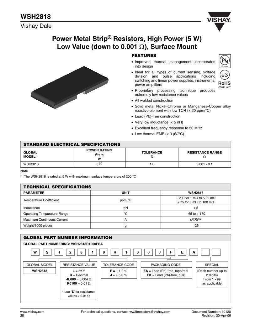
WSH2818Vishay Dale
FEATURES• Improved thermal management incorporated
into design
• Ideal for all types of current sensing, voltagedivision and pulse applications includingswitching and linear power supplies, instruments,power amplifiers
• Proprietary processing technique producesextremely low resistance values
• All welded construction
• Solid metal Nickel-Chrome or Manganese-Copper alloyresistive element with low TCR (< 20 ppm/°C)
• Lead (Pb)-free construction
• Very low inductance (< 5 nH)
• Excellent frequency response to 50 MHz
• Low thermal EMF (< 3 µV/°C)
Note(1) The WSH2818 is rated at 5 W with maximum surface temperature of 200 °C
RoHSCOMPLIANT
Pb-free
e3
STANDARD ELECTRICAL SPECIFICATIONS
GLOBAL MODEL
POWER RATINGP70 °C
W
TOLERANCE%
RESISTANCE RANGE Ω
WSH2818 5 (1) 1.0 0.001 - 0.1
TECHNICAL SPECIFICATIONSPARAMETER UNIT WSH2818
Temperature Coefficient ppm/°C± 200 for 1 mΩ to 5.99 mΩ± 75 for 6 mΩ to 100 mΩ
Inductance ηH < 5
Operating Temperature Range °C - 65 to + 170
Maximum Continuous Current A (P/R)1/2
Weight/1000 pieces g 126
GLOBAL PART NUMBER INFORMATIONGLOBAL PART NUMBERING: WSH2818R1000FEA
GLOBAL MODEL RESISTANCE VALUE TOLERANCE CODE PACKAGING CODE SPECIAL
WSH2818 L = mΩ*R = Decimal
4L000 = 0.004 ΩR0100 = 0.01 Ω
* use “L” for resistance values < 0.01 Ω
F = ± 1.0 %J = ± 5.0 %
EA = Lead (Pb)-free, tape/reelEK = Lead (Pb)-free, bulk
(Dash number up to 2 digits)
From 1 - 99 as applicable
W 8182HS R 1 0 0 0 F E A

Document Number: 30120 For technical questions, contact: [email protected] www.vishay.comRevision: 20-Apr-06 29
WSH2818Power Metal Strip® Resistors, High Power (5 W)
Low Value (down to 0.001 Ω), Surface MountVishay Dale
DIMENSIONS
Note• Embossed carrier tape per EIA-481-2
L
W
T
H
ba
a
c
MODEL
DIMENSIONS in inches [millimeters]
RESISTANCERANGE
ΩL W H T
WSH2818
0.006 - 0.10.280 ± 0.010[7.1 ± 0.25]
0.180 ± 0.010[4.6 ± 0.25]
0.032 ± 0.010[0.813 ± 0.25]
0.125 ± 0.010[3.18 ± 0.25]
0.001 - 0.00590.280 ± 0.010[7.1 ± 0.25]
0.180 ± 0.010[4.6 ± 0.25]
0.045 ± 0.010[1.143 ± 0.25]
0.125 ± 0.010[3.18 ± 0.25]
MODEL SOLDER PAD DIMENSIONS in inches [millimeters]
a b C
WSH28180.138[3.5]
0.200[5.1]
0.024[0.61]
70Derating
120
100
80
60
40
20
0- 65 - 50 - 25 0 25 50 75 100 125 150 170
Ambient Temperature in °C
Rat
ed P
ow
er in
%
PERFORMANCETEST CONDITIONS OF TEST TEST LIMITS
Thermal Shock - 55 °C to + 150 °C, 1000 cycles, 15 min at each extreme ± 0.5 % ΔR
Short Time Overload 4 x rated power for 5 s ± 1.0 % ΔR
Low Temperature Operation - 65 °C for 45 min ± 0.5 % ΔR
High Temperature Exposure 1000 h at + 170 °C ± 1.0 % ΔR
Bias Humidity + 85 °C, 85 % RH, 10 % Bias, 1000 h ± 0.5 % ΔR
Mechanical Shock 100 g’s for 6 ms, 5 pulses ± 0.5 % ΔR
Vibration Frequency varied 10 to 2000 Hz in 1 min, 3 directions, 12 h ± 0.5 % ΔR
Load Life 1000 h at + 70 °C, 1.5 h “ON”, 0.5 h “OFF” ± 1.0 % ΔR
Resistance to Solder Heat + 260 °C Solder, 10 - 12 s dwell, 25 mm/s emergence ± 0.5 % ΔR
Moisture Resistance MIL-STD-202, Method 106, 0 % power, 7b not required ± 0.5 % ΔR
PACKAGING
MODELREEL
TAPE WIDTH DIAMETER PIECES/REEL CODE
WSH2818 16 mm/Embossed Plastic 330 mm/13" 3500 EA

Power Metal Strip® Resistors,Low Value (down to 0.001 Ω), Surface Mount
www.vishay.com For technical questions, contact: [email protected] Document Number: 3010130 Revision: 26-Mar-07
WSRVishay Dale
FEATURES• Molded high temperature encapsulation
• Ideal for all types of current sensing, voltagedivision and pulse applications includingswitching and linear power supplies,instruments, power amplifiers
• Proprietary processing technique producesextremely low resistance values (down to0.001 Ω)
• All welded construction• Solid metal Nickel-Chrome or Manganese-Copper alloy
resistive element with low TCR (< 20 ppm/°C)• Solderable terminations• Very low inductance 0.5 nH to 5 nH• Excellent frequency response to 50 MHz• Low thermal EMF (< 3 µV/°C)• Lead (Pb)-free version is RoHS compliant
Note(1) The WSR3 requires a minimum of 1050 sq. mil. circuit traces connecting to the recommended solder pad• Part Marking: DALE, Model, Value, Tolerance, Date Code
* Pb containing terminations are not RoHS compliant, exemptions may apply
Available
Pb-free
RoHS* COMPLIANT
e2
STANDARD ELECTRICAL SPECIFICATIONS
GLOBALMODEL
SIZEPOWER RATING
P70 °C
W
RESISTANCE RANGE Ω
± 0.5 % ± 1.0 %WSR2 4527 2.0 0.01 - 1.0 0.001 - 1.0WSR3 4527 3.0 (1) 0.01 - 0.2 0.001 - 0.2
TECHNICAL SPECIFICATIONSPARAMETER UNIT WSR2 & WSR3
Temperature Coefficient ppm/°C 0.005 Ω - 0.0099 Ω = ± 1100.010 Ω - 1.0 Ω = ± 75
Dielectric Withstanding Voltage VAC > 500Insulation Resistance Ω > 109
Operating Temperature Range °C - 65 to + 275Maximum Working Voltage V (P x R)1/2
Weight/1000 pieces (typical) g 440
GLOBAL MODEL VALUE TOLERANCE PACKAGINGWSR2WSR3
L = mΩ* D = ± 0.5 % EA = Lead (Pb)-free, tape/reelR = Decimal F = ± 1.0 % EK = Lead (Pb)-free, bulk
5L000 = 0.005 Ω J = ± 5.0 % TA = Tin/lead, tape/reel (R86) R0100 = 0.01 Ω BA = Tin/Lead, bulk (B43)
GLOBAL PART NUMBER INFORMATION
WSR2 0.005 Ω 1 % R86
HISTORICAL MODEL RESISTANCE VALUE TOLERANCE CODE PACKAGING
SPECIAL(Dash Number)(up to 2 digits)From 1 - 99 as
applicable
W S R 2 5 L 0 0 0 F T A
* use “L” for resistancevalues < 0.01 Ω
NEW GLOBAL PART NUMBERING: WSR25L000FTA (PREFERRED PART NUMBERING FORMAT)
HISTORICAL PART NUMBER EXAMPLE: WSR2 0.005 Ω 1 % R86 (WILL CONTINUE TO BE ACCEPTED)

WSRPower Metal Strip® Resistors,
Low Value (down to 0.001 Ω), Surface MountVishay Dale
Document Number: 30101 For technical questions, contact: [email protected] www.vishay.comRevision: 26-Mar-07 31
DIMENSIONS
Note
• Embossed Carrier Tape per EIA-481-2
MODEL DIMENSIONS in inches [millimeters]
L H T W W1
WSR2WSR3
0.455 ± 0.032[11.56 ± 0.813]
0.095 ± 0.005[2.41 ± 0.127]
0.100 ± 0.010[2.54 ± 0.254]
0.275 ± 0.005[6.98 ± 0.127]
0.215 ± 0.005[5.46 ± 0.127]
MODEL SOLDER PAD DIMENSIONS in inches [millimeters]
a b l
WSR2WSR3
0.155[3.94]
0.230[5.84]
0.205[5.21]
W
L
T
W1
H
I
a
b
Derating- 65 - 25 25 75 125 175 225 275
Ambient Temperature °C70
0
20
40
60
80
100
120
Rat
ed P
ow
er in
%
PERFORMANCE
TEST CONDITIONS OF TESTTEST LIMITS
WSR2 WSR3
Thermal Shock - 55 °C to + 150 °C, 1000 cycles, 15 min at each extreme ± (0.5 % + 0.0005 Ω) ΔR ± (0.5 % + 0.0005 Ω) ΔR
Short Time OverloadWSR2: 5 x rated power for 5 sWSR3: 4 x rated power for 5 s
± (0.5 % + 0.0005 Ω) ΔR ± (2.0 % + 0.0005 Ω) ΔR
Low Temperature Storage - 65 °C for 24 h ± (0.5 % + 0.0005 Ω) ΔR ± (0.5 % + 0.0005 Ω) ΔRHigh Temperature Exposure
1000 h at + 275 °C ± (1.0 % + 0.0005 Ω) ΔR ± (1.0 % + 0.0005 Ω) ΔR
Bias Humidity + 85 °C, 85 % RH, 10 % Bias, 1000 h ± (0.5 % + 0.0005 Ω) ΔR ± (0.5 % + 0.0005 Ω) ΔRMechanical Shock 100 g’s for 6 ms, 5 pulses ± (0.5 % + 0.0005 Ω) ΔR ± (0.5 % + 0.0005 Ω) ΔRVibration Frequency varied 10 to 2000 Hz in 1 min, 3 directions, 12 h ± (0.5 % + 0.0005 Ω) ΔR ± (0.5 % + 0.0005 Ω) ΔRLoad Life 1000 h at rated power, + 70 °C, 1.5 h “ON”, 0.5 h “OFF” ± (1.0 % + 0.0005 Ω) ΔR ± (2.0 % + 0.0005 Ω) ΔRResistance to Solder Heat
+ 260 °C Solder, 10 - 12 s dwell, 25 mm/s emergence ± (0.5 % + 0.0005 Ω) ΔR ± (0.5 % + 0.0005 Ω) ΔR
Moisture Resistance MIL-STD-202 Method 106, 0 % power, 7a and 7b not required ± (0.5 % + 0.0005 Ω) ΔR ± (0.5 % + 0.0005 Ω) ΔR
PACKAGING
MODELREEL
TAPE WIDTH DIAMETER PIECES/REEL CODE
WSR2 and WSR3 24 mm/Embossed Plastic 330 mm/13" 1500 EA

Power Metal Strip® Resistors, High Power (5 W), Low Value (down to 0.001 Ω), Surface Mount
www.vishay.com For technical questions, contact: [email protected] Document Number: 3105932 Revision: 12-Jul-07
WSR High PowerVishay Dale
FEATURES• Molded high temperature encapsulation• Improved thermal management incorporated
into design• Ideal for all types of current sensing, voltage
division and pulse applications includingswitching and linear power supplies,instrumentation, power amplifiers
• Proprietary processing technique producesextremely low resistance values (down to 0.001 Ω)
• All welded construction• Solid metal Nickel-Chrome or Manganese-Copper alloy
resistive element with low TCR (< 20 ppm/°C)• Solderable terminations• Very low inductance 0.5 nH to 5 nH• Excellent frequency response to 50 MHz• Low thermal EMF (< 3 µV/°C)• Lead (Pb)-free version is RoHS compliant• Integral heat sink not utilized for resistance values less
than 0.0075 Ω
Note(1) The WSR5 is rated at 5 W with terminal temperature maintained ≤ 120 °C• Part Marking: DALE, Model, Value, Tolerance, Date Code
* Pb containing terminations are not RoHS compliant, exemptions may apply
Available
Pb-free
RoHS* COMPLIANT
e2
STANDARD ELECTRICAL SPECIFICATIONSGLOBALMODEL SIZE POWER RATING
P70 °C WRESISTANCE RANGE Ω
± 0.5 % ± 1 %WSR5 4527 5.0 (1) 0.01 - 0.3 0.001 - 0.3
TECHNICAL SPECIFICATIONSPARAMETER UNIT WSR5
Temperature Coefficient ppm/°C 0.0075 Ω to 0.0099 Ω = ± 1100.01 Ω to 0.3 Ω = ± 75
Dielectric Withstanding Voltage VAC > 500Insulation Resistance Ω > 109
Operating Temperature Range °C - 65 to + 275Maximum Working Voltage V (P x R)1/2
Weight/1000 pieces g 476
GLOBAL MODEL VALUE TOLERANCE PACKAGING SPECIALWSR5 L = mΩ* D = ± 0.5 % EA = Lead (Pb)-free, tape/reel (Dash Number)
R = Decimal F = ± 1.0 % EK = Lead (Pb)-free, bulk (up to 2 digits)5L000 = 0.005 Ω J = ± 5.0 % TA = Tin/lead, tape/reel (R86) From 1 - 99 as R0100 = 0.01 Ω BA = Tin/lead, bulk (B43) applicable
GLOBAL PART NUMBER INFORMATION
WSR5 0.01 Ω 1 % R86
HISTORICAL MODEL RESISTANCE VALUE TOLERANCE CODE PACKAGING
W S R 5 R 0 1 0 0 F T A
* use “L” for resistancevalues < 0.01 Ω
NEW GLOBAL PART NUMBERING: WSR5R0100FTA (PREFERRED PART NUMBERING FORMAT)
HISTORICAL PART NUMBER EXAMPLE: WSR5 0.01 Ω 1 % R86 (WILL CONTINUE TO BE ACCEPTED)
WSR High PowerPower Metal Strip® Resistors, High Power (5 W),
Low Value (down to 0.001 Ω), Surface MountVishay Dale
Document Number: 31059 For technical questions, contact: [email protected] www.vishay.comRevision: 12-Jul-07 33
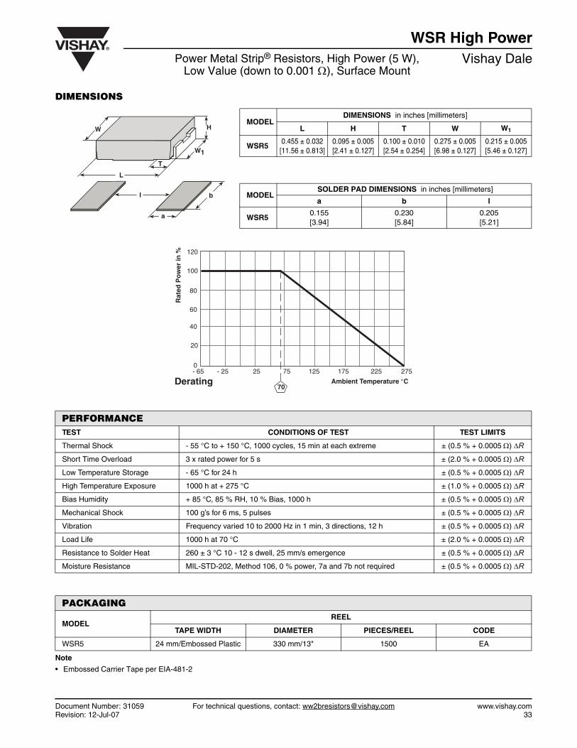
DIMENSIONS
Note
• Embossed Carrier Tape per EIA-481-2
MODEL DIMENSIONS in inches [millimeters]
L H T W W1
WSR50.455 ± 0.032[11.56 ± 0.813]
0.095 ± 0.005[2.41 ± 0.127]
0.100 ± 0.010[2.54 ± 0.254]
0.275 ± 0.005[6.98 ± 0.127]
0.215 ± 0.005[5.46 ± 0.127]
MODEL SOLDER PAD DIMENSIONS in inches [millimeters]
a b l
WSR50.155[3.94]
0.230[5.84]
0.205[5.21]
W H
W1
T
L
I
a
b
Derating- 65 - 25 25 75 125 175 225 275
Ambient Te mperature °C
0
20
40
60
80
100
120
70
Rat
ed P
ow
er in
%
PERFORMANCETEST CONDITIONS OF TEST TEST LIMITS
Thermal Shock - 55 °C to + 150 °C, 1000 cycles, 15 min at each extreme ± (0.5 % + 0.0005 Ω) ΔR
Short Time Overload 3 x rated power for 5 s ± (2.0 % + 0.0005 Ω) ΔR
Low Temperature Storage - 65 °C for 24 h ± (0.5 % + 0.0005 Ω) ΔR
High Temperature Exposure 1000 h at + 275 °C ± (1.0 % + 0.0005 Ω) ΔR
Bias Humidity + 85 °C, 85 % RH, 10 % Bias, 1000 h ± (0.5 % + 0.0005 Ω) ΔR
Mechanical Shock 100 g’s for 6 ms, 5 pulses ± (0.5 % + 0.0005 Ω) ΔR
Vibration Frequency varied 10 to 2000 Hz in 1 min, 3 directions, 12 h ± (0.5 % + 0.0005 Ω) ΔR
Load Life 1000 h at 70 °C ± (2.0 % + 0.0005 Ω) ΔR
Resistance to Solder Heat 260 ± 3 °C 10 - 12 s dwell, 25 mm/s emergence ± (0.5 % + 0.0005 Ω) ΔR
Moisture Resistance MIL-STD-202, Method 106, 0 % power, 7a and 7b not required ± (0.5 % + 0.0005 Ω) ΔR
PACKAGING
MODELREEL
TAPE WIDTH DIAMETER PIECES/REEL CODE
WSR5 24 mm/Embossed Plastic 330 mm/13" 1500 EA

Power Metal Strip® Resistors, Low Value, Surface Mount
www.vishay.com For technical questions, contact: [email protected] Document Number: 3013334 Revision: 19-Oct-07
WSR2...3Vishay Dale
FEATURES
• Ideal for all types of current sensing, voltage division andpulse applications including switching and linear powersupplies, instruments and power amplifiers
• Proprietary processing technique produces extremely lowresistance values down to 0.002 Ω
• All welded construction
• Solid metal Manganese-Copper alloy resistive elementwith low TCR (< 20 ppm/°C)
• Solderable terminations
• Low Thermal EMF (< 3 µV/°C)
• Very low inductance 0.5 ηH to 5 ηH
• Excellent frequency response to 50 MHz
STANDARD ELECTRICAL SPECIFICATIONS
MODELPOWER RATING
P70 °C
W
TOLERANCE%
RESISTANCE RANGEΩ
WSR2-3 3.0 1.0 0.002 to 0.005
TECHNICAL SPECIFICATIONS
PARAMETER UNIT WSR2-3
Temperature Coefficient ppm/°C ± 175
Inductance ηH < 3
Operating Temperature Range °C - 65 to + 170
Maximum Working Voltage V (P x R)1/2
Weight/1000 pieces g 169
GLOBAL PART NUMBER INFORMATIONGLOBAL PART NUMBERING: WSR23L000FEA3
GLOBAL MODEL RESISTANCE VALUE TOLERANCE CODE PACKAGING CODE SPECIAL
WSR2 L = mΩ2L000 = 0.002 Ω5L000 = 0.005 Ω
D = ± 0.5 %F = ± 1.0 %J = ± 5.0 %
EA = Lead (Pb)-free, tape/reelEK = Lead (Pb)-free, bulk
TA = Tin/lead, tape/reel (R86)BA = Tin/lead bulk (B43)
3 for special design with no
mold compound
2RSW 3 L 0 0 0 F E A 3

Document Number: 30133 For technical questions, contact: [email protected] www.vishay.comRevision: 19-Oct-07 35
WSR2...3Power Metal Strip® Resistors, Low Value, Surface Mount Vishay Dale
DIMENSIONS in inches [millimeters]
Note(1) 0.1" x 0.1" area in the center of the resistor will be flat and free of any trim cuts to facilitate pick & place nozzle.
Note• Embossed Carrier Tape per EIA-481-2
MODEL DIMENSIONS SOLDER PAD DIMENSIONS
L W H T a b l
WSR2-3 0.400 ± 0.010[10.16 ± 0.254]
0.215 ± 0.010[5.46 + 0.254]
0.029 ± 0.005[0.737 ± 0.127]
0.075 ± 0.010[1.91 ± 0.254]
0.100[2.540]
0.235[5.969]
0.240[5.080]
H
L
T
W
I
ab
(1)
70Derating
120
100
80
60
40
20
0- 65 - 50 - 25 0 25 50 75 100 125 150 170
Ambient Temperature in °C
Rat
ed P
ow
er in
%
PERFORMANCETEST CONDITIONS OF TEST TEST LIMITS
Thermal Shock - 55 °C to + 150 °C, 1000 cycles, 15 min at each extreme ± (0.5 % + 0.0005 Ω) ΔR
Short Time Overload 5 x rated power for 5 s for WSL2512 size and smaller ± (1.0 % + 0.0005 Ω) ΔR
Low Temperature Operation - 65 °C for 24 h ± (0.5 % + 0.0005 Ω) ΔR
High Temperature Exposure 1000 h at + 170 °C ± (1.0 % + 0.0005 Ω) ΔR
Bias Humidity + 85 °C, 85 % RH, 10 % Bias, 1000 h ± (0.5 % + 0.0005 Ω) ΔR
Mechanical Shock 100 g’s for 6 ms, 5 pulses ± (0.5 % + 0.0005 Ω) ΔR
Vibration Frequency varied 10 to 2000 Hz in 1 min 3 directions, 12 h ± (0.5 % + 0.0005 Ω) ΔR
Load Life 1000 h at 70 °C, 1.5 h “ON”, 0.5 h “OFF” ± (2.0 % + 0.0005 Ω) ΔR
PACKAGING
MODELREEL
TAPE WIDTH DIAMETER PIECES/REEL CODE
WSR2-3 24 mm/Embossed Plastic 330 mm/13" 5000 EA

Power Metal Strip® Resistors (Extended Range)Surface Mount
www.vishay.com For technical questions, contact: [email protected] Document Number: 3010936 Revision: 13-Oct-06
WSEVishay Dale
FEATURES
• 0805 size resistors with 0.25 W power rating
• Smaller footprint than a 1206 resistor (uses 40 % lessboard space)
• Superior overload and pulse handling capability
• SMD alternative for low power leaded wirewound resistors
• Low TCR 15 ppm/°C
• Low noise: < - 40 dB
• Voltage Coefficient: < 0.00001 %/V (< 0.1 ppm/V)
• Very low inductance: < 0.08 µH
STANDARD ELECTRICAL SPECIFICATIONS
MODEL SIZEPOWER RATING
P70 °C
W
LIMITING ELEMENT VOLTAGE
V
TEMPERATURE COEFFICIENT
ppm/K
RESISTANCE RANGEΩ
E-SERIES± 0.1 %, ± 0.25 %, ± 0.5 %, ± 1 %
WSE0805 0805 0.25 (P x R)1/2 15, 25 10 - 10K 96
TECHNICAL SPECIFICATIONSPARAMETER UNIT WSE0805
Dielectric Withstanding Voltage VAC 200
Insulation Resistance Ω > 109
Operating Temperature Range °C - 65 to + 150
Weight/1000 pieces g 5.5
GLOBAL PART NUMBER INFORMATIONGLOBAL PART NUMBERING: WSE08051K500FXEA
GLOBALMODEL
RESISTANCEVALUE
TOLERANCE CODE TCR CODE PACKAGING CODE SPECIAL
WSE0805 R = DecimalK = Thousand100R0 = 100 Ω4K000 = 4 kΩ
B = ± 0.1 %C = ± 0.25 %D = ± 0.5 %F = ± 1.0 %
X = ± 15 ppm/°CE = ± 25 ppm/°C
EA = Lead (Pb)-free, tape/reelEK = Lead (Pb)-free, bulk
TG = Tin/Lead, tape/reel (RT1)BA = Tin/Lead, bulk (B43)
(Dash Number)(up to 2 digits)
from 1 - 99as applicable
E 0 8 0 5 1 K 5 0 0 F EW S X A

WSEPower Metal Strip® Resistors (Extended Range)
Surface MountVishay Dale
Document Number: 30109 For technical questions, contact: [email protected] www.vishay.comRevision: 13-Oct-06 37
DIMENSIONS
Note(1) Land pattern dimensions (G, X, Z) are per IPC-782A
Note
• Embossed Carrier Tape per EIA-481-1A
L
D
W
T
Top Coating
Z
G X
RECOMMENDED LAND PATTERN
MODELDIMENSIONS in inches [millimeters]
D L W T G (1) X (1) Z (1)
WSE08050.015 ± 0.005[0.38 ± 0.13]
0.080 ± 0.005[2.30 ± 0.13]
0.050 ± 0.005[1.27 ± 0.13]
0.025 max[0.64 max]
0.028 ± 0.004[0.70 ± 0.10]
0.050 ± 0.004[1.27 ± 0.10]
0.122 ± 0.004[3.103 ± 0.10]
60
50
40
30
20
10
00.00 0.05 0.10 0.15 0.20 0.25
Power in Watts
Tem
per
atu
re R
ise
in °
C
Temperature Rise
120
100
80
60
40
20
0- 55 - 25 0 25 50 75 100 125 150 175
70 Ambient Temperature in °C
Rat
ed P
ow
er in
%%
Derating
PERFORMANCETEST CONDITIONS OF TEST TEST LIMITS
Thermal Shock - 65 °C to + 150 °C, 100 cycles, 15 min at each extreme ± 0.10 % ΔRShort Time Overload 5 x rated power for 5 s ± 0.10 % ΔRLow Temperature Operation - 65 °C, 0.25 W for 45 min ± 0.05 % ΔRHigh Temperature Exposure 100 h at + 150 °C ± 0.10 % ΔRMoisture Resistance MIL-STD-202, Method 106, 0 % power, 7b not required ± 0.10 % ΔRLoad Life 1000 h at 70 °C, 1.5 h “ON”, 0.5 h “OFF” ± 0.05 % ΔRResistance to Bonding Exposure 260 °C for 10 s ± 0.10 % ΔR
PACKAGING
MODELREEL
TAPE WIDTH DIAMETER PIECES/REEL CODE
WSE0805 8 mm/Punched Paper 178 mm/7" 5000 EA

Power Metal Strip® Flip Chip (Extended Range)Patents Pending
WSL....EVishay Dale
www.vishay.com For technical questions, contact: [email protected] Document Number: 2003338 Revision: 20-Mar-07
FEATURES• SMD alternative for low power leaded wirewound resistors• Excellent stability in different environmental conditions
(< 0.5 % change in resistance)• Superior overload and pulse handling capability as
compared to thin film (as much as 2 x better)• Low TCR, down to ± 15 ppm/K• Low noise: < 0.01 µVrms/V• Voltage coefficient: < 0.00001 %/V (< 0.1 ppm/V)• Very low inductance: < 0.08 µH
Notes• Ask about further value ranges, tighter tolerances and TCR’s• Power rating depends on the max. temperature at the solder point, the component placement density and the substrate material• 4-Digit Marking, according to MIL-PRF-55342 (except as noted in Ordering Information table), on top side(1) Rated voltage: (2) Contact factory using e-mail address at bottom of this page for resistance values available between 0R5 - 10R for 1506 and 0R5 - 100R for
2010 and 2512
Notes(3) Rated voltage: (4) Depending on solder pad dimensions
Note• Embossed Carrier Tape per EIA-481-1.2
STANDARD ELECTRICAL SPECIFICATIONS
GLOBALMODEL
SIZE INCH
POWER RATING
P70 °C
LIMITING ELEMENTVOLTAGE MAX (1)
V≅
TEMPERATURECOEFFICIENT
ppm/K
TOLERANCE%
RESISTANCERANGE (2)
ΩE-SERIES
WSL1506E 1506 0.25 63 15, 25 0.5, 1 0R5 - 10K 96WSL2010E 2010 0.5 100 15, 25 0.5, 1 0R5 - 10K 96WSL2512E 2512 1.0 100 15, 25 0.5, 1 0R5 - 10K 96
TECHNICAL SPECIFICATIONSPARAMETER UNIT WSL1506E WSL2010E WSL2512ERated Dissipation at 70 °C W 0.25 0.5 1.0Limiting Element Voltage (3) V ≅ 63 100 100Insulation Voltage (1 min) Vdc/ac peak 200 200 200Thermal Resistance K/W ≤ 220 (4) ≤ 88 (4) ≤ 65 (4)
Insulation Resistance MΩ > 106
Category Temperature Range °C - 55 to + 150Weight/1000 pieces g 12 25 35
PxR
PxR
PACKAGING
MODELREEL
TAPE WIDTH DIAMETER PIECES/REEL CODEWSL1506E 12 mm/Embossed Plastic 180 mm/7" 4000 EAWSL2010E 12 mm/Embossed Plastic 180 mm/7" 4000 EAWSL2512E 12 mm/Embossed Plastic 180 mm/7" 2000 EA
GLOBAL PA RT NUMBER INFORMA TION
W S L 1 5 0 6 E 1 0 E 0 X E A
WSL1506E E = ± 25 ppm/K X = ± 15 ppm/K
(Dash Number)(up to 2 digits)From 1 - 99 as
applicable
Resistance T olerance ( ± )
0.50.50.5
1.01.01.0
Multiplier
X1X1000
X1 000 000
X1X1000
X1 000 000
Symbol
WXY
DEF
GLOBAL MODEL TOLERANCE CODE SPECIAL RESISTANCE VALUE & TOLERANCE PA CKAGING EA = Lead (Pb)-free, tape/reel
EK = Lead (Pb)-free, bulk
TA = Tape/reel (R86)BA = Bulk (B43)
NEW GLOBAL PART NUMBERING: WSL1506E10E0XEA

Document Number: 20033 For technical questions, contact: [email protected] www.vishay.comRevision: 20-Mar-07 39
WSL....EPower Metal Strip® Flip Chip (Extended Range)
Patents PendingVishay Dale
DIMENSIONS
Pulse Energy Plot:This represents the energy in each of 50 pulses, with a1 second rest between pulses, that it takes to shift theWSL....E resistance ± (0.50 % + 0.01 Ω).
L
T
d
D
W
I
a
b
SIZEINCH
Dimensions in inches [millimeters]
L W Tmax D d
15060.15 ± 0.005[3.81 ± 0.13]
0.062 ± 0.003[1.57 ± 0.08]
0.025[0.64]
0.012 ± 0.003[0.30 ± 0.08]
0.059 ± 0.003[1.50 ± 0.08]
20100.200 ± 0.005[5.08 ± 0.13]
0.100 ± 0.003[2.54 ± 0.08]
0.025[0.64]
0.020 ± 0.003[0.51 ± 0.08]
0.097 ± 0.003[2.46 ± 0.08]
25120.250 ± 0.005[6.35 ± 0.13]
0.126 ± 0.003[3.20 ± 0.08]
0.025[0.64]
0.024 ± 0.003[0.61 ± 0.08]
0.123 ± 0.003[3.12 ± 0.08]
SIZEINCH
Solder Pad Dimensions in inches [millimeters]
a b l
1506 0.015 [0.38] 0.062 [1.57] 0.118 [3.00]
2010 0.023 [0.58] 0.100 [2.54] 0.153 [3.89]
2512 0.027 [0.69] 0.126 [3.20] 0.196 [4.98]
Pulse Energy
1.E+00
1.E+01
1.E+02
1.E+03
1.E+04
1.E+02 1.E+03 1.E+04 1.E+05Time in Microseconds
Pu
lse
En
erg
y in
mJo
ule
s
WSL2512EWSL1506E
WSL2010E
0 0.25 0.50 0.75 1.0
Power in W
WSL1506E WSL2010E
WSL2512E
150
125
100
75
50
25
0
Temperature Rise
Tem
per
atir
e R
ise
in °
C
- 55 - 25 0 25 50 75 100 125 150 175
Ambient Temperature in °C
120
100
80
60
40
20
0
70Derating
Rat
ed P
ow
er in
%
PERFORMANCETEST CONDITIONS OF TEST TEST LIMITSThermal Shock - 55 °C to + 150 °C, 100 cycles, 15 min at each extreme ± (0.20 % + 0.01 Ω)Short Time Overload 5 x rated power for 5 s ± (0.20 % + 0.01 Ω)Low Temperature Storage - 65 °C for 24 h ± (0.20 % + 0.01 Ω)High Temperature Exposure 1000 h at + 150 °C ± (0.50 % + 0.01 Ω)Moisture Resistance MIL-STD-202, Method 106, 0 % power, 7a and 7b not required ± (0.50 % + 0.01 Ω)Load Life 1000 h at rated power, + 70 °C, 1.5 h “ON”, 0.5 h “OFF” ± (0.50 % + 0.01 Ω)Vibration MIL-STD-202, Method 204D ± (0.10 % + 0.01 Ω)Mechanical Shock 100 g’s for 6 ms, 5 pulses ± (0.10 % + 0.01 Ω)Resistance to Soldering Heat + 260 °C Solder, 10 - 12 s dwell, 25 mm/s emergence ± (0.50 % + 0.01 Ω)

www.vishay.com40
Vishay Dale

Contents
WSMS5515 .......................... 42
WSBS8518 ........................... 44
Power Metal Strip® Resistors
Special

Power Metal Strip® Meter Shunt Resistor,Very Low Value (down to 0.00016 Ω)
www.vishay.com For technical questions, contact: [email protected] Document Number: 3013542 Revision: 15-Nov-07
WSMS5515Vishay Dale
FEATURES• High power to resistor size ratio
• 4-Terminal (Kelvin) connection design
• Proprietary processing technique producesextremely low resistance values
• All welded construction
• RoHS compliant, lead (Pb)-free construction
• Very low inductance (< 0.5 nH)
• Excellent frequency response to 50 MHz
• Low thermal EMF (< 3 µV/°C)
RoHSCOMPLIANT
STANDARD ELECTRICAL SPECIFICATIONS
GLOBAL MODEL
POWER RATINGP70 °C
W
TOLERANCE%
RESISTANCE VALUEAVAILABLE
µΩ
WEIGHT(Typical)
g
WSMS5515 3.0 5.0 160, 200, 250, 300, 500 7.8
TECHNICAL SPECIFICATIONS
PARAMETER UNIT RESISTOR CHARACTERISTICS
Temperature Coefficient ppm/°C160 µΩ, 200 µΩ and 250 µΩ = ± 225
300 µΩ and 500 µΩ = ± 175
Operating Temperature Range °C - 65 to + 170
Maximum Current Rating A (P/R)1/2
GLOBAL PART NUMBER INFORMATIONGLOBAL PART NUMBERING: WSMS5515L2500JK (WSMS5515, 0.00025 Ω, ± 5 %)
GLOBAL MODEL RESISTANCE VALUE TOLERANCE CODE PACKAGING CODE SPECIAL
WSMS5515 L = mΩL1600 = 0.00016 ΩL2000 = 0.00020 ΩL2500 = 0.00025 ΩL3000 = 0.00030 ΩL5000 = 0.00050 Ω
J = ± 5.0 % K = Bulk pack (Dash number)(up to 2 digits)From 1 - 99 as
applicable
W 155SMS 5 L 2 5 0 0 J K

Document Number: 30135 For technical questions, contact: [email protected] www.vishay.comRevision: 15-Nov-07 43
WSMS5515Power Metal Strip® Meter Shunt Resistor,
Very Low Value (down to 0.00016 Ω)Vishay Dale
DIMENSIONS in inches
1.441
1.005
0.724
0.4880.079
0.142
0.0790.156
0.142
0.079
2.165 ± 0.0101.5750.295
CALIBRATION CUT
R 0.020 (2)
0.080 x 45° CHAH. (4)
R 0.078 REF. (1)R 0.028 (4)
R 0.020 (2)
Ø 0.244 THRU (2)
0.056
0.138
0.295
0.590
TOLERANCES ON DECIMALSXXX ± 0.005
RESISTANCEVALUE (µΩ)
RESISTORTHICKNESS
(inches)
ELEMENTMATERIAL
160 0.051 Mn-Cu
200 0.051 Mn-Cu
250 0.033 Mn-Cu
300 0.033 Mn-Cu
500 0.059 Fe-Cr70
Derating
120
100
80
60
40
20
0- 65 - 50 - 25 0 25 50 75 100 125 150 170
Ambient Temperature in °C
Rat
ed P
ow
er in
%
PERFORMANCE
TEST CONDITIONS OF TEST TEST LIMITS
Thermal Shock - 55 °C to + 150 °C, 1000 cycles, 15 min at each extreme ± 0.5 % ΔR
Short Time Overload 5 x rated power for 5 s ± 0.5 % ΔR
Low Temperature Operation - 65 °C for 45 min ± 0.5 % ΔR
High Temperature Exposure 1000 h at + 170 °C ± 1.0 % ΔR
Bias Humidity + 85 °C, 85 % RH, 10 % Bias, 1000 h ± 0.5 % ΔR
Mechanical Shock 100 g’s for 6 ms, 5 pulses ± 0.5 % ΔR
Vibration Frequency varied 10 to 2000 Hz in 1 min, 3 directions, 12 h ± 0.5 % ΔR
Load Life 1000 h at + 70 °C, 1.5 h “ON”, 0.5 h “OFF” ± 1.0 % ΔR
Moisture Resistance MIL-STD-202, Method 106, 0 % power, 7b not required ± 0.5 % ΔR

Power Metal Strip® Battery Shunt Resistor,Very Low Value (100 µΩ and 125 µΩ)
www.vishay.com For technical questions, contact: [email protected] Document Number: 3013444 Revision: 01-Feb-08
WSBS8518Vishay Dale
FEATURES• High power to resistor size ratio
• Proprietary processing technique producesextremely low resistance values
• All welded construction
• RoHS compliant, lead (Pb)-free construction
• Very low inductance (< 5 nH)
• Excellent frequency response to 50 MHz
• Low thermal EMF (< 3 µV/°C)
RoHSCOMPLIANT
STANDARD ELECTRICAL SPECIFICATIONS
GLOBAL MODEL
POWER RATINGP70 °C
W
TOLERANCE%
RESISTANCE VALUEµΩ
WEIGHT(Typical)
g
WSBS8518 36 5.0 100, 125 46.3
TECHNICAL SPECIFICATIONS
PARAMETER UNIT RESISTOR CHARACTERISTICS
Temperature Coefficient ppm/°C ± 225
Operating Temperature Range °C - 65 to + 170
Maximum Current Rating A (P/R)1/2
GLOBAL PART NUMBER INFORMATIONGLOBAL PART NUMBERING: WSBS8518L1250JK (WSBS8518, 0.000125 Ω, ± 5 %)
GLOBAL MODEL RESISTANCE VALUE TOLERANCE CODE PACKAGING CODE SPECIAL
WSBS8518 L = mΩL1000 = 0.000100 ΩL1250 = 0.000125 Ω
J = ± 5.0 % K = Bulk pack (Dash number)(up to 2 digits)From 1 - 99 as
applicable
W 158SBS 8 L 1 2 5 0 J K
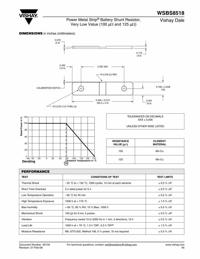
Document Number: 30134 For technical questions, contact: [email protected] www.vishay.comRevision: 01-Feb-08 45
WSBS8518Power Metal Strip® Battery Shunt Resistor,
Very Low Value (100 µΩ and 125 µΩ)Vishay Dale
DIMENSIONS in inches (millimeters)
0.118(3.0)
0.078(2.0)
0.492(12.5)
2.362 (60)
R 0.078 (2) REF.
CALIBRATION NOTCH
Ø 0.276 (7.0) THRU (2)
3.346 ± 0.015(85.0 ± 0.4)
0.708 ± 0.008(18)
0.354(9.0)
TOLERANCES ON DECIMALSXXX ± 0.005
UNLESS OTHER WISE LISTED
RESISTANCEVALUE (µΩ)
ELEMENTMATERIAL
100 Mn-Cu
125 Mn-Cu70
Derating
120
100
80
60
40
20
0- 65 - 50 - 25 0 25 50 75 100 125 150 170
Ambient Temperature in °C
Rat
ed P
ow
er in
%
PERFORMANCE
TEST CONDITIONS OF TEST TEST LIMITS
Thermal Shock - 55 °C to + 150 °C, 1000 cycles, 15 min at each extreme ± 0.5 % ΔR
Short Time Overload 5 x rated power for 5 s ± 0.5 % ΔR
Low Temperature Operation - 65 °C for 45 min ± 0.5 % ΔR
High Temperature Exposure 1000 h at + 170 °C ± 1.0 % ΔR
Bias Humidity + 85 °C, 85 % RH, 10 % Bias, 1000 h ± 0.5 % ΔR
Mechanical Shock 100 g’s for 6 ms, 5 pulses ± 0.5 % ΔR
Vibration Frequency varied 10 to 2000 Hz in 1 min, 3 directions, 12 h ± 0.5 % ΔR
Load Life 1000 h at + 70 °C, 1.5 h “ON”, 0.5 h “OFF” ± 1.0 % ΔR
Moisture Resistance MIL-STD-202, Method 106, 0 % power, 7b not required ± 0.5 % ΔR

www.vishay.com46
Vishay Dale
Contents
LVR ...................................... 48
SR ........................................ 50
CPCL .................................... 52
CPL ...................................... 54
CPSL .................................... 56Power Metal Strip® Resistors
Leaded

Wirewound Resistors, Precision Power, Low Value,Commercial, Military, MIL-PRF-49465 Type RLV, Axial Lead
LVRVishay Dale
www.vishay.com For technical questions, contact: [email protected] Document Number: 3020648 Revision: 07-Jan-08
FEATURES• Ideal for all types of current sensing applications
including switching and linear power supplies,instruments and power amplifiers
• Proprietary processing technique producesextremely low resistance values
• Excellent load life stability• Low temperature coefficient• Low inductance• Cooler operation for high power to size ratio
Notes(1) Resistance is measured 3/8" [9.52 mm] from the body of the resistor, or at 1.183" [30.05 mm], 1.315" [33.40 mm], 1.675" [42.545 mm] or
2.575" [65.405 mm] spacing for the LVR01, LVR03, LVR05 and LVR10 respectively.(2) Standard resistance values are 0.01 Ω, 0.015 Ω, 0.02 Ω, 0.025 Ω, 0.03 Ω, 0.033 Ω, 0.04 Ω, 0.05 Ω, 0.051 Ω, 0.06 Ω, 0.068 Ω, 0.07 Ω, 0.08 Ω,
0.09 Ω and 0.1 Ω with 1 % tolerance. Other resistance values may be available upon request.
* Pb containing terminations are not RoHS compliant, exemptions may apply
Available
Pb-free
RoHS*COMPLIANT
e3
STANDARD ELECTRICAL SPECIFICATIONSGLOBAL MODEL
HISTORICALMODEL
MIL-PRF-49465TYPE
POWER RATINGP25 °C W
RESISTANCE RANGE Ω (1)
± 1 %, ± 3 %, ± 5 %, ± 10 % TECHNOLOGY
LVR01 LVR-1 - 1 0.01 - 0.1 (2) Metal StripLVR03 LVR-3 - 3 0.005 - 0.2 Metal StripLVR03...26 LVR-3-26 RLV30 (M4946506) 3 0.01 - 0.2 Metal StripLVR05 LVR-5 - 5 0.005 - 0.3 Metal StripLVR05...26 LVR-5-26 RLV30 (M4946507) 5 0.01 - 0.3 Metal StripLVR10 LVR-10 - 10 0.01 - 0.8 Coil Spacewound
TECHNICAL SPECIFICATIONSPARAMETER UNIT LVR01 LVR03 LVR05 LVR10Rated Power at + 25 °C W 1 3 5 10Operating Temperature Range °C - 65/+ 175 - 65/+ 275Dielectric Withstanding Voltage VAC 1000 1000 1000 1000Insulation Resistance Ω 10 000 MΩ minimum dryShort Time Overload - 5 x rated power for 5 s 10 x rated power for 5 sTerminal Strength (minimum) lb 5 10 10 10Temperature Coefficient ppm/°C See TCR vs Resistance Value ChartMaximum Working Voltage V (P x R)1/2
Weight (maximum) g 2 2 5 11
GLOBAL PART NUMBER INFORMATIONNew Global Part Numbering: LVR055L000FS73 (preferred part number format)
GLOBAL MODEL VALUE TOLERANCE PACKAGING SPECIAL
LVR01LVR03LVR05LVR10
R = DecimalL = mΩ
(values < 0.010 Ω)R1500 = 0.15 Ω7L000 = 0.007 Ω
D = ± 0.5 %F = ± 1.0 %G = ± 2.0 %H = ± 3.0 %J = ± 5.0 %
K = ± 10.0 %
E12 = Lead (Pb)-free bulkE03 = Lead (Pb)-free lacer pack (LVR10)
E70 = Lead (Pb)-free, tape/reel 1000 pieces (LVR01, 03)E73 = Lead (Pb)-free, tape/reel 500 pieces
(Dash Number)(up to 3 digits)From 1 - 999as applicable
B12 = Tin/lead bulkL03 = Tin/lead lacer pack (LVR10)
S70 = Tin/lead, tape/reel 1000 pieces (LVR01, 03)S73 = Tin/lead, tape/reel 500 pieces
Historical Part Number example: LVR-5 0.005 Ω 1 % S73 (will continue to be accepted for tin/lead product only)
LVR-5 0.005 Ω 1 % S73
HISTORICAL MODEL RESISTANCE VALUE TOLERANCE CODE PACKAGING
V R 0 5 5 L 0 0 0 F S 7 3L

LVRWirewound Resistors, Precision Power, Low Value,
Commercial, Military, MIL-PRF-49465 Type RLV, Axial LeadVishay Dale
Document Number: 30206 For technical questions, contact: [email protected] www.vishay.comRevision: 07-Jan-08 49
DIMENSIONS in inches [millimeters]
Note(1) On some standard reel pack methods, the leads may be trimmed to a shorter length than shown.
MATERIAL SPECIFICATIONSElement: Self-supporting nickel-chrome alloy(LVR10 also utilizes manganin)
Encapsulation: High temperature mold compound
Terminals: Tinned copper
Part Marking: DALE, model, wattage, value, tolerance,date code
The improved TCR characteristics of these LVR models from- 55 °C to + 125 °C (reference to + 25 °C) are as follows:
1.50 [38.10] (1)
MinimumA
CB
MODELDIMENSIONS in inches [millimeters]A
± 0.010 [0.254]B
± 0.010 [0.254]C
± 0.002 [0.051]LVR01 0.427 [10.85] 0.115 [2.92] 0.020 [0.508]LVR03 0.560 [14.22] 0.205 [5.21] 0.032 [0.813]LVR05 0.925 [23.50] 0.330 [8.38] 0.040 [1.02]LVR10 1.828 [46.43] 0.392 [9.96] 0.040 [1.02]
1 2 3 4 5 6 7 8 9 10
250
200
150
100
50
NI E
RU
TA
RE
PM
ET
EC
AFR
US
°C
POWER IN W
LVR03
LVR01
Surface Temperature vs Power
LVR05 LVR10
20 40 60 80 100
RESISTANCE (Ω x 10-3)
LVR05
400
300
200
100
TC
R IN
pp
m/°
C
LVR03
LVR01
TCR vs Resistance Value
LVR10
- 65 - 25 25 75 125 175 225 275
AMBIENT TEMPERATURE IN °C
120
100
80
60
40
20
0
%
N
I
R
E
W
O
P
D
E
T
A
R
LVR01
LVR03 LVR05 LVR10
Derating
PERFORMANCETEST CONDITIONS OF TEST TEST LIMITS
Thermal Shock - 65 °C to + 125 °C, 5 cycles, 15 min at each extrem ± (0.2 % + 0.0005 Ω) ΔRShort Time Overload 5 x rated power (LVR01, 03, 05), 10 x rated power (LVR10) for 5 s ± (0.5 % + 0.0005 Ω) ΔRLow Temperature Storage - 65 °C for 24 h ± (0.2 % + 0.0005 Ω) ΔRHigh Temperature Exposure 250 h at + 275 °C (+ 175 °C for LVR01) ± (2.0 % + 0.0005 Ω) ΔRDielectric Withstanding Voltage 1000 Vrms, 1 min ± (0.1 % + 0.0005 Ω) ΔRInsulation Resistance MIL-STD-202 Method 302, 100 V 1000 MΩ minimum
Moisture Resistance MIL-STD-202 Method 106, 100 7b not applicable ± (0.2 % + 0.0005 Ω) ΔRShock, Specified Pulse MIL-STD-202 Method 213, 100 g's for 6 ms, 10 shocks ± (0.1 % + 0.0005 Ω) ΔRVibration, High Frequency Frequency varied 10 to 2000 Hz, 20 g peak, 2 directions 6 h each ± (0.1 % + 0.0005 Ω) ΔRLoad Life 2000 h at rated power, + 25 °C, 1.5 h “ON”, 0.5 h “OFF” ± (2.0 % + 0.0005 Ω) ΔRSolderability ANSI J-STD-002 95 % coverage
Bias Humidity + 85 °C, 85 % RH, 10 % bias, 1000 h ± (1.0 % + 0.0005 Ω) ΔR

www.vishay.com For technical questions, contact: [email protected] Document Number: 3106750 Revision: 22-Nov-07
SRVishay Dale
Wirewound Resistors, Open Air, Current Sense, Low Value
FEATURES• Open air design• Low resistance values for all types of current
sensing, voltage division and pulse applicationsincluding switching and linear supplies,instrumentation and power amplifiers
• All welded construction
• Solid metal nickel-chrome or copper-nickel alloyresistive element
• Solderable terminations
• Very low inductance
• Lead (Pb)-free version is RoHS compliant
* Pb containing terminations are not RoHS compliant, exemptions may apply
STANDARD ELECTRICAL SPECIFICATIONS
MODELPOWER RATING
P70 °C
W
TOLERANCE± %
RESISTANCE RANGEΩ
SR1 1.0 1, 5 0.005 - 0.03
SR3 3.0 1, 5 0.005 - 0.05
SR5 5.0 1, 5 0.004 - 0.05
TECHNICAL SPECIFICATIONSPARAMETER UNIT SR Resistor Characteristics
Temperature Coefficient ppm/°C0.004 Ω - 0.005 Ω = ± 300
0.0051 Ω - 0.0099 Ω = ± 1750.01 Ω - 0.05 Ω = ± 100
Operating Temperature Range °C - 65 to + 275
Maximum Continuous Current A (P/R)1/2
SAP ORDERING INFORMATION (Part Number 18 digits)
Global Part Numbering Example: SR55L000JE14
GLOBAL MODEL VALUE TOLERANCE PACKAGING SPECIAL
SR1SR3SR5
L = mΩ(below 0.01 Ω)R = Decimal
5L000 = 0.005 ΩR0100 = 0.01 Ω
F = ± 1.0 %J = ± 5.0 %K = ± 10 %
E14 = Lead (Pb)-free bulk
B14 = Tin/lead bulk
(Dash Number)(up to 3 digits)
From 1 - 999 asapplicable
Available
Pb-free
RoHS*COMPLIANT
e3
L 0 0 0 J E 15S 5R 4

Document Number: 31067 For technical questions, contact: [email protected] www.vishay.comRevision: 22-Nov-07 51
SRWirewound Resistors, Open Air,
Current Sense, Low ValueVishay Dale
DIMENSIONS in inches [millimeters]
MATERIAL SPECIFICATIONS
Element: Nickel-chrome or copper-nickel alloy dependingon resistance value
Terminals: Tinned copper
Encapsulation: None
Marking: None
F
E
E
FA
C
B
A
C
SR1 SR3 and SR5
0.112[2.85]max.
0.050 ± 0.010[1.27 ± 0.254]
0.312 [7.95]typ.
MODELDIMENSIONS in inches [millimeters]
A B C E F
SR10.450 + 0.020
[11.43 + 0.508]-
0.125 ± 0.030[3.18 ± 0.762]
0.070[1.78]
0.040 ± 0.002[1.02 ± 0.051]
SR30.600 + 0.040/- 0.020
[15.24 + 1.020/- 0.508] 1.0 maximum[25.4 maximum]
0.065 + 0.010/- 0.005[1.65 + 0.254/- 0.127]
SR50.800 + 0.040/- 0.020
[20.32 + 1.020/- 0.508]
Derating- 65 - 25 25 75 125 175 225 275
AMBIENT TEMPERATURE IN °C
0
20
40
60
80
100
120
70
RA
TE
D P
OW
ER
IN %
PERFORMANCETEST CONDITIONS OF TEST TEST LIMITS
Temperature Cycling - 55 °C to + 125 °C, 1000 cycles, 15 min at each extreme ± (1.0 % + 0.0005 Ω) ΔR
Low Temperature Storage - 65 °C for 24 h ± (0.5 % + 0.0005 Ω) ΔR
High Temperature Exposure 1000 h at + 275 °C ± (2.0 % + 0.0005 Ω) ΔR
Bias Humidity + 85 °C, 85 % RH, 10 % bias, 1000 h ± (1.0 % + 0.0005 Ω) ΔR
Mechanical Shock 100 g’s for 11 ms, 5 pulses ± (0.2 % + 0.0005 Ω) ΔR
Vibration Frequency varied 10 to 2000 Hz in 1 min, 3 directions, 12 h ± (0.2 % + 0.0005 Ω) ΔR
Load Life 1000 h at rated power, + 70 °C, 1.5 h “ON”, 0.5 h “OFF” ± (2.0 % + 0.0005 Ω) ΔR
Resistance to Solder Heat + 260 °C solder, 10 - 12 s dwell, 25 mm/s emergence ± (0.5 % + 0.0005 Ω) ΔR
Moisture Resistance MIL-STD-202 Method 106, 0 % power, 7a and 7b not required ± (0.5 % + 0.0005 Ω) ΔR

Wirewound/Metal Film Resistors, Commercial Power,Vertical Mount
CPCL, CPCC, CPCP, CPCFVishay Dale
www.vishay.com For technical questions, contact: [email protected] Document Number: 3021852 Revision: 29-Oct-07
FEATURES• Space saving• Direct mounting on printed circuit board• Meets or exceeds requirements of
EIA-Standard RS-344• High power to size ratio• Special inorganic potting compound and
ceramic case provide high thermal conductivityin a fireproof package
* Pb containing terminations are not RoHS compliant, exemptions may apply
Available
Pb-free
RoHS*COMPLIANT
e3
STANDARD ELECTRICAL SPECIFICATIONSGLOBALMODEL
HISTORICALMODEL
POWER RATINGP70 °C W
TOLERANCE± %
RESISTANCE RANGEΩ
WEIGHT (Typical)g
CPCL02 CPCL-2 2 5, 10 0.01 - 0.10 3.5CPCC02 CPCC-2 2 5, 10 0.1 - 500 3.5CPCP02 CPCP-2 2 1, 5 0.1 - 4K 3.5CPCF02 CPCF-2 2 1, 5, 10 501 - 150K 3.5CPCL03 CPCL-3 3 5, 10 0.01 - 0.10 5.5CPCC03 CPCC-3 3 5, 10 0.1 - 800 5.5CPCP03 CPCP-3 3 1, 5 0.1 - 5K 5.5CPCF03 CPCF-3 3 1, 5, 10 801 - 150K 5.5CPCL05 CPCL-5 5 5, 10 0.01 - 0.10 6.9CPCC05 CPCC-5 5 5, 10 0.1 - 800 6.9CPCP05 CPCP-5 5 1, 5 0.1 - 5K 6.9CPCF05 CPCF-5 5 1, 5, 10 801 - 150K 6.9CPCP07 CPCP-7 7 3, 5, 10 0.1 - 430 9.2CPCL10 CPCL-10 10 5, 10 0.01 - 0.10 14.3CPCC10 CPCC-10 10 5, 10 0.1 - 1.5K 14.3CPCP10 CPCP-10 10 1, 5 0.1 - 8K 14.3
TECHNICAL SPECIFICATIONSPARAMETER UNIT CPCLxx CPCCxx CPCPxx CPCFxx
Temperature Coefficient ppm/°C 0.01 Ω - 0.049 Ω = ± 4000.05 Ω - 0.1 Ω = ± 100
0.1 Ω - 0.99 Ω = ± 6001.0 Ω and above = ± 300
0.1 Ω - 0.99 Ω = ± 901.0 Ω - 9.9 Ω = ± 50
10 Ω and above = ± 20
± 50 all values
Short Time Overload - 5 x rated power for 5 sMaximum Working Voltage V (P x R)1/2
Operating Temperature Range °C - 65/+ 275 - 65/+ 225Terminal Strength lb 10 minimumDielectric Withstanding Voltage VAC 1000
GLOBAL PART NUMBER INFORMATIONNew Global Part Numbering: CPCC0515R00JB32 (preferred part number format)
GLOBAL MODEL VALUE TOLERANCE PACKAGING SPECIAL
(See Standard Electrical Specifications Global
Model column for options)
R = DecimalK = Thousand
R1500 = 0.15 Ω1K500 = 1500 Ω
F = ± 1.0 %H = ± 3.0 %J = ± 5.0 %
K = ± 10.0 %
E32 = Lead (Pb)-free two layer bulkE01 = Lead (Pb)-free skin pack
(Dash Number)(up to 3 digits)From 1 - 999as applicable
B32 = Tin/lead two layer bulkJ01 = Tin/lead skin pack
Historical Part Number example: CPCC-5 15 Ω 5 % B32 (will continue to be accepted for tin/lead product only)
CPCC-5 15 Ω 5 % B32
HISTORICAL MODEL RESISTANCE VALUE TOLERANCE CODE PACKAGING
P C C 0 5 1 5 R 0 0 J B 3 2C

CPCL, CPCC, CPCP, CPCFWirewound/Metal Film Resistors, Commercial Power,
Vertical MountVishay Dale
Document Number: 30218 For technical questions, contact: [email protected] www.vishay.comRevision: 29-Oct-07 53
DIMENSIONS in inches [millimeters]
MATERIAL SPECIFICATIONSPart Marking: DALE, model, wattage, value, tolerance, datecodeCPCL: Element: Self-supporting copper-nickel alloy ornickel-chrome alloy, depending on resistance valueBody: Steatite ceramic case with inorganic potting compoundTerminals: Tinned copperCPCC: Element: Copper-nickel alloy or nickel-chrome alloy,depending on resistance valueCore: Woven fiberglassBody: Steatite ceramic case with inorganic potting compoundEnd Caps: Tin plated steelTerminals: Tinned copperCPCP: Element: Copper-nickel alloy or nickel-chrome alloy,depending on resistance valueCore: CeramicBody: Steatite ceramic case with inorganic potting compoundEnd Caps: Stainless steel (CPCP07 is tin plated CRS)Terminals: Tinned Copperweld® (CPCP07 is tin plated copper)CPCF: Element: Metal film - nickel-chrome alloyCore: Alumina ceramicBody: Steatite ceramic case with inorganic potting compoundEnd Caps: Brass alloyTerminals: Solder-coated copper
A
E
D
C
B
0.177[4.50 ]+ 1.98
- 0.991
+ 0.078- 0.039
GLOBAL MODEL
DIMENSIONS in inches [millimeters]
A± 0.031 [0.794]
B± 0.031 [0.794]
C+ 0.043 [1.09]- 0.012 [0.305]
D± 0.005 [0.127]
E± 0.040 [1.02]
CPCL02CPCC02CPCP02CPCF02
0.807 [20.50] 0.433 [11.00] 0.276 [7.01] 0.032 [0.813] 0.197 [5.00]
CPCL03CPCC03CPCP03CPCF03
0.984 [24.99] 0.472 [11.99] 0.315 [8.00] 0.032 [0.813] 0.197 [5.00]
CPCL05CPCC05CPCP05CPCF05
1.003 [25.48] 0.512 [13.00] 0.354 [8.99] 0.032 [0.813] 0.197 [5.00]
CPCP07 1.535 ± 0.059[39.00 ± 1.50]
0.512 ± 0.043[13.00 ± 1.10]
0.354 ± 0.043[9.00 ± 1.10]
0.032 ± 0.005[0.813 ± 0.127]
0.197 + 0.079/-0.039[5.00 + 2.0/- 1.0]
CPCL10CPCP10 1.372 [34.85] 0.633 [16.08] 0.485 [12.32]
0.040 [1.02]0.290 [7.37]
CPCC10 0.036 [0.914]
AMBIENT TEMPERATURE IN °CDerating
RA
TE
D P
OW
ER
IN %
CPCL CPCC CPCP
CPCF
- 65 - 25 25 75 125 175 225 27570
0
20
40
60
80
100
120
PERFORMANCETEST CONDITIONS OF TEST CPCP TEST LIMITS CPCC, CPCL, CPCF
TEST LIMITSThermal Shock - 55 °C to + 275 °C, 5 cycles, 30 min dwell time ± (2.0 % + 0.05 Ω) ΔR ± (5.0 % + 0.05 Ω) ΔRShort Time Overload 5 x rated power for 5 s ± (2.0 % + 0.05 Ω) ΔR ± (4.0 % + 0.05 Ω) ΔRDielectric Withstanding Voltage 1000 Vrms for 1 min ± (0.1 % + 0.05 Ω) ΔR ± (2.0 % + 0.05 Ω) ΔRLow Temperature Storage - 65 °C, full rated working voltage for 45 min ± (2.0 % + 0.05 Ω) ΔR ± (3.0 % + 0.05 Ω) ΔRBias Humidity 75 °C, 90 % - 100 % RH, 240 h ± (2.0 % + 0.05 Ω) ΔR ± (5.0 % + 0.05 Ω) ΔR
Load Life 1000 h at rated power, + 40 °C, 1.5 h “ON”, 0.5 h “OFF” ± (5.0 % + 0.05 Ω) ΔR ± (5.0 % + 0.05 Ω) ΔR
Terminal Strength 5 to 10 s 10 pound pull test ± (1.0 % + 0.05 Ω) ΔR ± (1.0 % + 0.05 Ω) ΔRResistance to Solder Heat Terminal immersed 3.5 s in molten solder up to body ± (1.0 % + 0.05 Ω) ΔR ± (4.0 % + 0.05 Ω) ΔR

Wirewound Resistors, Commercial Power,Axial Lead, Low Value
CPLVishay Dale
www.vishay.com For technical questions, contact: [email protected] Document Number: 3021254 Revision: 12-Jan-06
FEATURES• High power to size ratio• Low inductance• Ceramic cases are available with circuit board
stand-offs (designated with a -3 model ending)• Superior surge capability• Extremely low resistance values• Complete welded construction• Special inorganic potting compound and
ceramic case provide high thermal conductivityin a fireproof package
Notes(1) Resistance is measured 3/8" [9.52 mm] from resistor body.(2) ± 1 % and ± 3 % available
* Pb containing terminations are not RoHS compliant, exemptions may apply
Available
Pb-free
RoHS*COMPLIANT
e3
STANDARD ELECTRICAL SPECIFICATIONS
GLOBALMODEL
HISTORICALMODEL
POWER RATINGP40 °C
W
RESISTANCE RANGE (1)
Ω± 5 % Standard (2)
WEIGHT(Typical)
g
CPL03 CPL-3 3 0.01 - 0.10 3.4
CPL03...3 CPL-3-3 3 0.01 - 0.10 3.6
CPL05 CPL-5 5 0.01 - 0.10 4.8
CPL05...3 CPL-5-3 5 0.01 - 0.10 5.0
CPL07 CPL-7 7 0.01 - 0.10 6.8
CPL07...3 CPL-7-3 7 0.01 - 0.10 7.0
CPL10 CPL-10 10 0.01 - 0.10 9.5
CPL10...3 CPL-10-3 10 0.01 - 0.10 9.9
CPL15 CPL-15 15 0.01 - 0.10 16.8
CPL15...3 CPL-15-3 15 0.01 - 0.10 17.4
TECHNICAL SPECIFICATIONSPARAMETER UNIT CPL RESISTOR CHARACTERISTICSTemperature Coefficient ppm/°C ± 300
Short Time Overload - 5 × rated power for 5 s
Maximum Working Voltage V (P x R)1/2
Operating Temperature Range °C - 65/+ 275
Terminal Strength lb 10 minimum
Dielectric Withstanding Voltage VAC 1000
GLOBAL PART NUMBER INFORMATIONNew Global Part Numbering: CPL05R0500JB143 (preferred part numbering format)
GLOBAL MODEL VALUE TOLERANCE PACKAGING SPECIAL
CPL03CPL05CPL07CPL10CPL05
R = DecimalR1000 = 0.10 Ω
F = ± 1.0 %G = ± 2.0 %H = ± 3.0 %J = ± 5.0 %
K = ± 10.0 %
E14 = Lead (Pb)-free bulkE31 = Lead (Pb)-free four layer bulk
E01 = Lead (Pb)-free skin pack
(Dash Number)(up to 3 digits)From 1 - 999as applicableB14 = Tin/lead bulk
B31 = Tin/lead four layer bulkJ01 = Tin/lead skin pack
Historical Part Number example: CPL-5-3 0.05 Ω 5 % B14 (will continue to be accepted)
CPL-5-3 0.05 Ω 5 % B14
HISTORICAL MODEL RESISTANCE VALUE TOLERANCE CODE PACKAGING
P L 0 5 R 0 5 0 0 J B 1 4 3C

CPLWirewound Resistors, Commercial Power,
Axial Lead, Low ValueVishay Dale
Document Number: 30212 For technical questions, contact: [email protected] www.vishay.comRevision: 12-Jan-06 55
DIMENSIONS in inches [millimeters]
Note(1) Potting compound may extend outside of ceramic case up to 0.060 [1.52] maximum per side.
MATERIAL SPECIFICATIONS
Element: Self-supporting copper-nickel alloy or nickel-chrome alloy, depending on resistance range
Body: Steatite ceramic case with inorganic pottingcompound
Terminals: Tinned copper
Part Marking: DALE, model, wattage, value, tolerance, datecode
AB
C
CPLxxE1.0 [25.4]
minimum
0.125 [3.18]typical
1.0 [25.4]minimum
D
B
CPLxx...3
E
C
A
GLOBAL MODEL
DIMENSIONS in inches [millimeters]
A (1)
± 0.031 [0.794]B
± 0.031 [0.794]C
± 0.031 [0.794]C
± 0.031 [0.794]E
± 0.001 [0.025]
CPL03 0.875 [22.22] 0.313 [7.94] 0.313 [7.94] - 0.032 [0.813]
CPL03...3 0.875 [22.22] 0.313 [7.94] 0.313 [7.94] 0.375 [9.52] 0.032 [0.813]
CPL05 0.875 [22.22] 0.375 [9.52] 0.344 [8.73] - 0.032 [0.813]
CPL05...3 0.875 [22.22] 0.375 [9.52] 0.344 [8.73] 0.406 [10.32] 0.032 [0.813]
CPL07 1.391 [35.32] 0.375 [9.52] 0.344 [8.73] - 0.032 [0.813]
CPL07...3 1.391 [35.32] 0.375 [9.52] 0.344 [8.73] 0.469 [11.91] 0.032 [0.813]
CPL10 1.875 [47.62] 0.375 [9.52] 0.344 [8.73] - 0.032 [0.813]
CPL10...3 1.875 [47.62] 0.375 [9.52] 0.344 [8.73] 0.469 [11.91] 0.032 [0.813]
CPL15 1.875 [47.62] 0.500 [12.70] 0.500 [12.70] - 0.032 [0.813]
CPL15...3 1.875 [47.62] 0.500 [12.70] 0.500 [12.70] 0.625 [15.87] 0.032 [0.813]
- 65 - 25 25 75 125 175 225 275
AMBIENT TEMPERATURE IN °CDerating
% NI
RE
WO
P D
ET
AR
40
0
20
40
60
80
100
120
PERFORMANCE
TEST CONDITIONS OF TEST TEST LIMITS (EIA RS-344)
Thermal Shock - 55 °C to + 275 °C, 5 cycles, 30 min dwell time ± (5.0 % + 0.05 Ω) ΔR
Short Time Overload 5 x rated power for 5 s ± (4.0 % + 0.05 Ω) ΔR
Dielectric Withstanding Voltage 1000 Vrms for 1 min ± (2.0 % + 0.05 Ω) ΔR
Low Temperature Operation - 65 °C, full rated working voltage for 45 min ± (3.0 % + 0.05 Ω) ΔR
Bias Humidity 75 °C, 90 % - 100 % RH, 240 h ± (5.0 % + 0.05 Ω) ΔR
Load Life 1000 h at rated power, + 40 °C, 1.5 h “ON”, 0.5 h “OFF” ± (5.0 % + 0.05 Ω) ΔR
Terminal Strength5 to 10 s 10 pound pull test, torsion test - 3 alternating directions,360° each
± (1.0 % + 0.05 Ω) ΔR
Resistance to Solder Heat Terminal immersed 3.5 s in molten solder at 1/8" to 3/16" from body ± (1.0 % + 0.05 Ω) ΔR

www.vishay.com For technical questions, contact: [email protected] Document Number: 3021756 Revision: 23-Mar-07
CPSLVishay Dale
Wirewound Resistors, Commercial Power, Four Terminal, Low Value
FEATURES• Low Inductance• Extremely low resistance values• Current sensing• Low temperature coefficients• High power to size ratio• Ceramic cases are available with circuit board
stand-offs (designated with a -3 model ending)• Superior surge capability• Complete welded construction• Special inorganic potting compound and ceramic case
provide high thermal conductivity in a fireproof package
SCHEMATIC
* Pb containing terminations are RoHS compliant, exemptions may apply
SenseLeads
CurrentLeads
STANDARD ELECTRICAL SPECIFICATIONS
GLOBAL MODEL HISTORICAL MODEL POWER RATING P40 °CW
RESISTANCE RANGE Ω± 5 % STANDARD, ± 3 % AVAILABLE
WEIGHT (TYPICAL)g
CPSL03...5 CPSL-3-5 3 0.01 to 0.10 4.0CPSL03...3 CPSL-3-3 3 0.01 to 0.10 4.2CPSL05...5 CPSL-5-5 5 0.01 to 0.10 5.2CPSL05...3 CPSL-5-3 5 0.01 to 0.10 5.4CPSL07...5 CPSL-7-5 7 0.01 to 0.10 7.6CPSL10...5 CPSL-10-5 10 0.01 to 0.10 10.2CPSL15...5 CPSL-15-5 15 0.01 to 0.10 18.9
TECHNICAL SPECIFICATIONSPARAMETER UNIT CPSL RESISTOR CHARACTERISTICSTemperature Coefficient ppm/°C ± 100 maximumShort Time Overload - 5 x rated power for 5 sMaximum Working Voltage V (P x R)1/2
Operating Temperature Range °C - 65/+ 275Terminal Strength lb 10 minimumDielectric Withstanding Voltage VAC 1000
GLOBAL PART NUMBER INFORMATIONNew Global Part Numbering: CPSL05R0500JB143 (preferred part number format)
GLOBAL MODEL VALUE TOLERANCE PACKAGING SPECIAL
CPSL03CPSL05CPSL07CPSL10CPSL15
R = DecimalR1000 = 0.10 Ω
F = ± 1.0 %G = ± 2.0 %H = ± 3.0 %J = ± 5.0 %
K = ± 10.0 %
E14 = Lead (Pb)-free bulkE31 = Lead (Pb)-free four layer bulk
(Dash Number)(up to 3 digits)From 1 - 999as applicableB14 = Tin/lead bulk
B31 = Tin/lead four layer bulk
Historical Part Number example: CPSL-5-3 0.05 Ω 5 % B14 (will continue to be accepted)
CPCSL-5-3 0.05 Ω 5 % B14
HISTORICAL MODEL RESISTANCE VALUE TOLERANCE CODE PACKAGING
Available
Pb-free
RoHS*COMPLIANT
e3
L 0 5 R 5 0 00P S J B 1C 34

Document Number: 30217 For technical questions, contact: [email protected] www.vishay.comRevision: 23-Mar-07 57
CPSLWirewound Resistors, Commercial Power,
Four Terminal, Low ValueVishay Dale
DIMENSIONS in inches [millimeters]
Note(1) Potting compound may extend outside of ceramic case up to 0.060 [1.52] maximum per side.
MATERIAL SPECIFICATIONS
Element: Self-supporting Copper-Nickel alloy or Nickel-Chrome alloy, depending on resistance value
Body: Steatite ceramic case with inorganic pottingcompound
Terminals: Tinned copper
Part Marking: Dale, model, wattage, value, tolerance, datecode
E
A
F
CPSLxx...5
C
1.0 [25.4]minimum B
1.50 ± 0.062[38.1 ±1.57]
A C
D B
25.4 [1.0]Minimum
CPSLxx...3
E
F
38.1 ± 1.57[1.50 ± 0.062]
GLOBALMODEL
DIMENSIONS in inches [millimeters]
A (1) ± 0.031 [0.794]
B ± 0.031 [0.794]
C ± 0.031 [0.794]
D ± 0.031 [0.794]
E ± 0.001 [0.025]
F± 0.063 [1.59]
CPSL03...5 0.875 [22.22] 0.313 [7.94] 0.313 [7.94] - 0.036 [0.914] 0.563 [14.30]
CPSL03...3 0.875 [22.22] 0.313 [7.94] 0.313 [7.94] 0.375 [9.52] 0.036 [0.914] 0.563 [14.30]
CPSL05...5 0.875 [22.22] 0.375 [9.52] 0.344 [8.73] - 0.036 [0.914] 0.563 [14.30]
CPSL05...3 0.875 [22.22] 0.375 [9.52] 0.344 [8.73] 0.438 [11.11] 0.036 [0.914] 0.563 [14.30]
CPSL07...5 1.391 [35.32] 0.375 [9.52] 0.344 [8.73] - 0.036 [0.914] 1.000 [25.40]
CPSL10...5 1.875 [47.62] 0.375 [9.52] 0.344 [8.73] - 0.036 [0.914] 1.375 [34.93]
CPSL15...5 1.875 [47.62] 0.500 [12.70] 0.500 [12.70] - 0.036 [0.914] 1.375 [34.93]
Derating
- 65 - 25 25 75 125 175 225 275
AMBIENT TEMPERATURE IN °C40
0
20
40
60
80
100
120
RA
TE
D P
OW
ER
IN %
PERFORMANCETEST CONDITIONS OF TEST TEST LIMITS
Thermal Shock - 55 °C to + 275 °C, 5 cycles, 30 min dwell time ± (5.0 % + 0.05 Ω) ΔR
Short Time Overload 5 x rated power for 5 s ± (4.0 % + 0.05 Ω) ΔRDielectric Withstanding Voltage
1000 Vrms for 1 min ± (2.0 % + 0.05 Ω) ΔR
Low Temperature Operation - 65 °C, full rated working voltage for 45 min ± (3.0 % + 0.05 Ω) ΔRBias Humidity 75 °C, 90 % - 100 % RH, 240 h ± (5.0 % + 0.05 Ω) ΔRLoad Life 1000 h at rated power, + 40 °C, 1.5 h “ON”, 0.5 h “OFF” ± (5.0 % + 0.05 Ω) ΔRTerminal Strength 5 to 10 s 10 pound pull test, torsion test - 3 alternating directions, 360° each ± (1.0 % + 0.05 Ω) ΔRResistance to Solder Heat Terminal immersed 3.5 s in molten solder at 1/8" to 3/16" from body ± (1.0 % + 0.05 Ω) ΔR

NotesVishay Dale
www.vishay.com58

one of the world’s largest
of Discrete semiconductors and passive Componentsmanufacturers
oNliNe iNformatioN
For product information and a current list of sales offices, representatives and distributors, visit our website:
www.vishay.com
tHe ameriCas
UNiteD statesVISHAY AMERICAS ONE GREENWICH PLACE SHELTON, CT 06484 uNITED STATES PH: +1-402-563-6866 FAx: +1-402-563-6296
asia
siNgaporeVISHAY INTERTECHNOLOGY ASIA PTE LTD.25 TAMPINES STREET 92 KEPPEL BuILDING #02-00 SINGAPORE 528877 PH: +65-6788-6668 FAx: +65-6788-0988
p.r. CHiNaVISHAY TRADING (SHANGHAI) CO., LTD.15D, SuN TONG INFOPORT PLAZA55 HuAI HAI WEST ROADSHANGHAI 200030P.R. CHINAPH: +86-21-5258-5000FAx: +86-21-5258-7979
JapaNVISHAY JAPAN CO., LTD.MG IKENOHATA BLDG. 4F 1-2-18, IKENOHATA TAITO-Ku TOKYO 110-0008 JAPAN PH: +81-3-5832-6210 FAx: +81-3-5832-6260
eUrope
germaNyVISHAY EuROPE SALES GMBHGEHEIMRAT-ROSENTHAL-STR. 100 95100 SELB GERMANY PH: +49-9287-71-0 FAx: +49-9287-70435 fraNCeVISHAY S.A.199, BLVD DE LA MADELEINE 06003 NICE, CEDEx 1 FRANCE PH: +33-4-9337-2920 FAx: +33-4-9337-2997 UNiteD KiNgDomVISHAY LTD.PALLION INDuSTRIAL ESTATESuNDERLAND SR4 6SuuNITED KINGDOMPH: +44-191-514-4155FAx: +44-191-567-8262
WO
RL
DW
IDE
SA
LE
S C
ON
TAC
TS

Copyright © 2008 by Vishay Intertechnology, Inc.
Registered Trademarks of Vishay Intertechnology, Inc.
All rights reserved. Printed in Germany.
Specifications subject to change without notice.
World HeadquartersVishay Intertechnology, Inc.63 Lancaster AvenueMalvern, PA 19355-2143united States
one of the world’s largest
of Discrete semiconductors and passive Componentsmanufacturers
w w w . v i s h a y . c o m
DA
TA
BO
OK
VSE-DB0089-0804
PO
WE
R M
ET
AL
ST
RIP
® R
ES
IST
OR
S