Power Management Considerations for Networked Devices
26
Design Tools for Networked SOCs ©2001 R. Gupta, ASP-DAC’01 1 Power Management Considerations for Power Management Considerations for Networked Devices Networked Devices Rajesh K. Gupta Center for Embedded Computer Systems University of California, Irvine Irvine, CA 92612 [email protected] 2 Outline Outline l Wireless networked system-on-chip design: I & II L Power management in networked SOCs n Energy consumption: where does it go? n Levels of power management u circuits and components, system architectural, application software, operating system policies n Circuit-level strategies n Architectural strategies n Application software strategies n OS strategies n Power management case studies u Power management in 802.11 u Power management in Bluetooth n Summary l Design tools for networked system-on-chip
Transcript of Power Management Considerations for Networked Devices

Design Tools for Networked SOCs©2001 R. Gupta, ASP-DAC’01 1
Power Management Considerations forPower Management Considerations forNetworked DevicesNetworked Devices
Rajesh K. Gupta
Center for Embedded Computer SystemsUniversity of California, Irvine
Irvine, CA [email protected]
2
OutlineOutline
l Wireless networked system-on-chip design: I & IIè Power management in networked SOCs
n Energy consumption: where does it go?n Levels of power management
u circuits and components, system architectural,application software, operating system policies
nCircuit-level strategiesn Architectural strategiesn Application software strategiesnOS strategiesn Power management case studies
u Power management in 802.11u Power management in Bluetooth
n Summaryl Design tools for networked system-on-chip
Design Tools for Networked SOCs©2001 R. Gupta, ASP-DAC’01 2
Design Tools forDesign Tools forNetworked System-on-ChipNetworked System-on-Chip
Rajesh K. Gupta
Center for Embedded Computer SystemsUniversity of California, Irvine
Irvine, CA [email protected]
4
OutlineOutline
l Wireless networked system-on-chip design: I & IIl Power management and portabilityè Design tools for networked system-on-chip
nDesign technology challenges in networked SOCsn Two views of Networked SOCs
u compositional (or ASIC view)u architectural (or network-centric view)
n Scope and categories of design tools for NSOCsn System-level composition through OO mechanismsnNetwork architectural modelingn Implementation tools
uRF circuit design tools:ä accurate device modeling; circuit simulationä antennae design and EM simulation tools
n Summary

Design Tools for Networked SOCs©2001 R. Gupta, ASP-DAC’01 3
5
System-ChipsSystem-Chips
l A “system” consists of partsn that are designed independently, and often without
knowledge of their eventual application(s)
l System-on-Chipn a system built from “pre-designed” partsn enormous challenges since “pre-designed” silicon parts
do not compose well across multiple design datarepresentation
n testing methods and ensuring testability is even harder
l SOCs in networking and wireless applicationsn face unique design and design technology challenges
due to component heterogeneity.
6
Design Technology Challenges inDesign Technology Challenges inNetworkedNetworked SOCs SOCs
l Inferior CMOS components compared to discrete counter-parts using bipolar and GaAs technologies
l Power, size, bandwidth limitations for on-chip processing
l An extremely tight control of chip, package parasitic RFpaths is needed for on-chip RF transceivers
l And yet the system-level performance can be higher due ton architectural design that is less sensitive to
device/technology limitations/variationsn the ability to integrate passive devices, sophisticated
signal processing and even digital computations toadapt to application, environment and evendevice/technology characteristics.
ò This requires ability to carry out rapid architectural anddesign space explorations.

Design Tools for Networked SOCs©2001 R. Gupta, ASP-DAC’01 4
7
How will we design theseHow will we design thesesystem-chips?system-chips?
l There are two distinct views of NSOC:nCompositional or ASIC view
u SOC design is a ultimately an integrated circuitdesign
u demands from mother-nature must be met.
nNetwork centric viewu Protocol and communication functions are central to
chip functionalityä “The really hard part is figuring out how to relate sub-system
performance enhancements to end-user performance.”ä “I find the hardest part to be making trade-offs so as to
optimize across the various layers (physical, link, network,transport, application) of the communication system. Weneed tools and techniques to co-design these layers,instead of separate black-box optimizations.”
l Regardless of the view, one fact is abundantly clear that:n IC Designer is also a networked systems designer.
Application
OS & Middleware
TransportCODECActuatorSensor
Peripherals Network
MAC/Link
Physical
Application
OS & Middleware
Transport CODECActuatorSensor
PeripheralsNetwork
MAC/Link
Physical
PROTOCOLS
Flow of bits
8
Compositional View: ASICCompositional View: ASIC
RF & IF Transceiver
Baseband Processing
CustomASICLogic
AlgorithmAccelerationCoprocessors
DSP Core
RAM/ROM
WirelessProtocol
ProcessorRAMROM
DRAM
Network/Host/PeripheralInterface
(Microcontroller)
RF Design
Signal Processing Algorithms
Application
Protocol design
Interface design
Design Tools for Networked SOCs©2001 R. Gupta, ASP-DAC’01 5
9
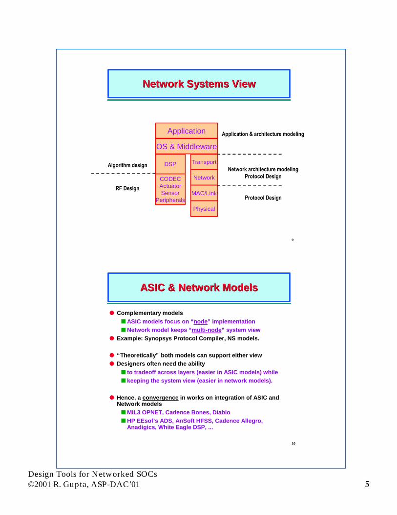
Network Systems ViewNetwork Systems View
Application
OS & Middleware
Transport
Network
MAC/Link
Physical
CODECActuatorSensor
Peripherals
DSP
Application & architecture modeling
Network architecture modelingProtocol Design
Protocol DesignRF Design
Algorithm design
10
ASIC & Network ModelsASIC & Network Models
l Complementary modelsn ASIC models focus on “node” implementationnNetwork model keeps “multi-node” system view
l Example: Synopsys Protocol Compiler, NS models.
l “Theoretically” both models can support either viewl Designers often need the ability
n to tradeoff across layers (easier in ASIC models) whilen keeping the system view (easier in network models).
l Hence, a convergence in works on integration of ASIC andNetwork modelsnMIL3 OPNET, Cadence Bones, DiablonHP EEsof’s ADS, AnSoft HFSS, Cadence Allegro,
Anadigics, White Eagle DSP, ...

Design Tools for Networked SOCs©2001 R. Gupta, ASP-DAC’01 6
11
Scope of NSOC Design ToolsScope of NSOC Design Tools
l Design of single-chip systems with radio transceiversrequires toolsn to explore new architectures containing heterogeneous
elementsn to explore circuit design containing analog/digital,
active/passive components (mixed signal design)n to accurately estimate parasitic effects, package effects
l Typically mixed-system design entailsn antennae designn network design: interference, user mobility, access to
shared resourcesn algorithmic simulationsn protocol designn circuit design, layout and estimation tools
12
Categories of Design ToolsCategories of Design Tools
¶ Architectural design toolsn network, protocol simulationsn algorithmic simulations, partitioning and mapping tools
· Design environment toolsn encapsulated libraries, library management for design
components¸Module design
n low noise integrated frequency synthesizersn base-band over-sampled data convertersn design of RF, analog, digital VLSI modules
¹ Modeling, characterization and validation toolsn characterization of mixed-mode designs, RF coupling
paths, EMIn simultaneous modeling, design and optimization of
antenna, passive RF filter, RF amp, RF receiver, poweramp. components
Design Tools for Networked SOCs©2001 R. Gupta, ASP-DAC’01 7
13
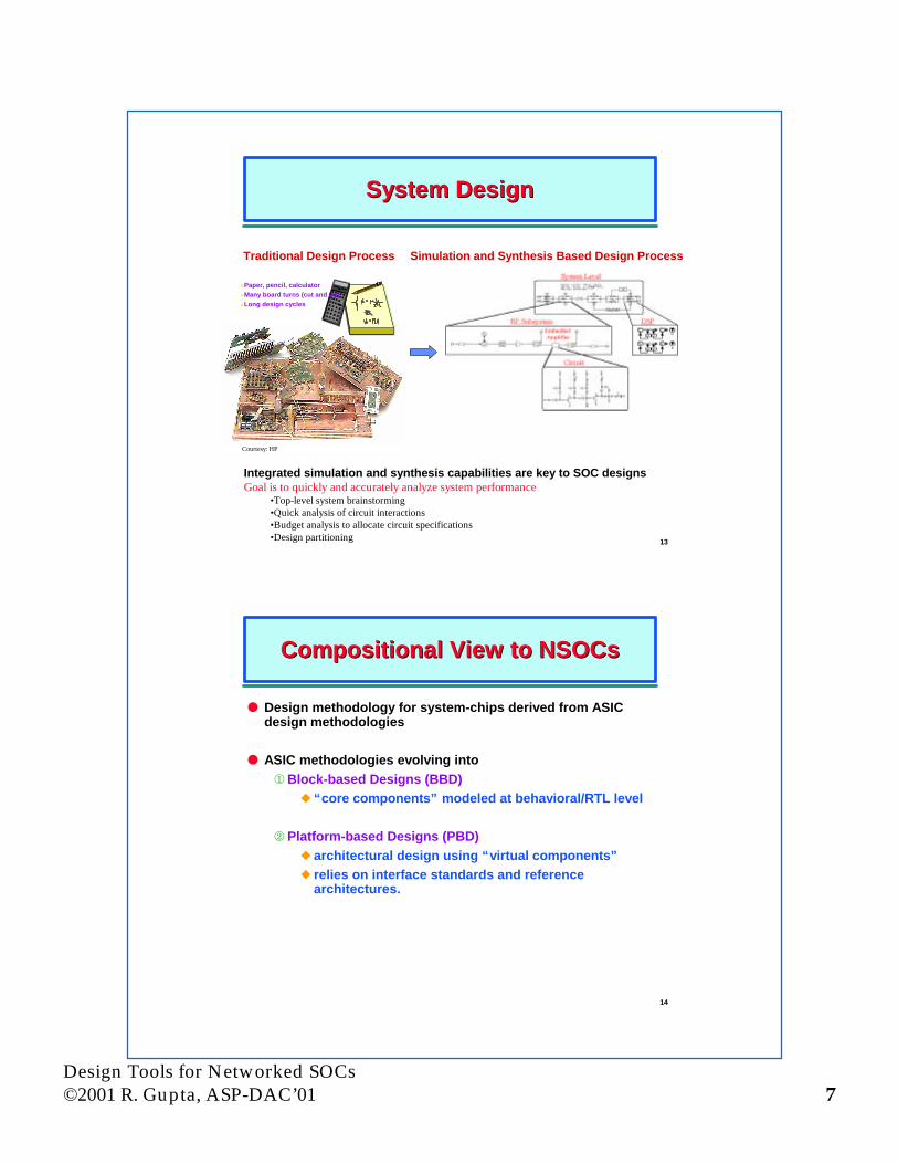
System DesignSystem Design
lPaper, pencil, calculatorlMany board turns (cut and try)lLong design cycles
Courtesy: HP
Traditional Design Process Simulation and Synthesis Based Design Process
Integrated simulation and synthesis capabilities are key to SOC designsGoal is to quickly and accurately analyze system performance
•Top-level system brainstorming•Quick analysis of circuit interactions•Budget analysis to allocate circuit specifications•Design partitioning
14
Compositional View to Compositional View to NSOCsNSOCs
l Design methodology for system-chips derived from ASICdesign methodologies
l ASIC methodologies evolving into¬Block-based Designs (BBD)
u “core components” modeled at behavioral/RTL level
Platform-based Designs (PBD)u architectural design using “virtual components”u relies on interface standards and reference
architectures.

Design Tools for Networked SOCs©2001 R. Gupta, ASP-DAC’01 8
15
Platform-based methodologyPlatform-based methodology
l Platform based design:n Application mapped on architecturen Performance evaluation and iterative
refinementl Challenges:
n complete system simulationn complexity managementn composability and reuse
l Key elements for composability¶ Identification and use of useful
models of computationu FSMD, DE, DF, CSP, ...
· A flexible, extensible languageplatform to capture the functionality.
l Composability can be achieved usingObject-oriented mechanisms:
UCI Balboa project:http://www.cecs.uci.edu/~balboa
16
Composability Composability in in BalboaBalboa
l Large design composed of small behavioral blocksl Design duality:
n Functional model: describe and synthesizen Structural model: capture and simulate
l Object mechanisms enables you to compose structural withfunctional information at the highest levels of abstraction

Design Tools for Networked SOCs©2001 R. Gupta, ASP-DAC’01 9
17
Structural information throughStructural information throughobject relationshipsobject relationships
lObject oriented design philosophynmapping of a physical object structure onto a
conceptual object structurel Structural information should be expressed in two
way:nclass diagram for the abstract viewusets of classes and relationships
nobject diagram for the concrete view:unetlist of entities communicating through
signalslWe can define and use object patterns at every layer of
abstraction
18
Object compositions throughObject compositions throughrelationships: FSMD examplerelationships: FSMD example

Design Tools for Networked SOCs©2001 R. Gupta, ASP-DAC’01 10
19
Different levels of abstractionDifferent levels of abstraction
l Patterns: set of extensible reoccurring design problems withknown solutionsn IP identification
l Object patterns at each level of abstraction for:nmodels of computation
u process networks, fsmd, etc.n components
u bus, signal, memory, cpu, logic block, ALUs,registers, latches, muxes, etc.
20
Different levels of abstraction (2)Different levels of abstraction (2)

Design Tools for Networked SOCs©2001 R. Gupta, ASP-DAC’01 11
21
Physical propertiesPhysical properties
22
The processor patternThe processor pattern

Design Tools for Networked SOCs©2001 R. Gupta, ASP-DAC’01 12
23
The bus-protocol patternThe bus-protocol pattern
24
MethodologyMethodology
l Step 1: Identify the model of computation:nwrite an early model of the specification with it, use
semantics to capture it formallyl Step 2: Identify the model of the architecture:
n define and allocate design unitsl Step 3: Distribute functionality on the structure:
n bind MoC to design unitsn distribute functionality across the structure with
polymorphisml Step 4: Iterative refinement by object decomposition
n compose a big object with smaller objects (throughpatterns)
n have smaller MoC and a growing number of smallercomponents

Design Tools for Networked SOCs©2001 R. Gupta, ASP-DAC’01 13
25
The UCIThe UCI Balboa Balboa Project Project
l Design expressed in terms ofobjects and relationships
l Object patterns for each levelof abstraction
l Abstract semantic used tostore the object, to be able touse different simulator andsynthesizer
26
Network Architectural DesignNetwork Architectural Design
or “behavioral design” for wireless systems
l Design network architecturen point-to-point, cellular, etc
l Design protocolsn specificationn verification at various levels: link, MAC, physical
l Tools in this categorynMatlab, Ptolemy (and likes)n network, protocol simulators
l Tools are designed for simulations specific to a design layer:n simulation tools for algorithm developmentn simulation tools for network protocolsn simulation tools for circuit design, hardware
implementation, etc.

Design Tools for Networked SOCs©2001 R. Gupta, ASP-DAC’01 14
27
Network Architecture Modeling: NSNetwork Architecture Modeling: NS
l Developed under the Virtual Internet Testbed (VINT) project(UCB, LBL, USC/ISI, Xerox PARC)
l Captures network nodes, topology and provides efficientevent driven simulations with a number of “schedulers”
l Interpreted interface forn network configuration, simulation setupn using existing simulation kernel objects such as
predefined network linksl Simulation model in C++ for
n packet processingn changing models of existing simulation kernel classes,
e.g., using a special queuing discipline.
28
Example:Example:A 4-node system with 2 “agents”, a traffic generatorA 4-node system with 2 “agents”, a traffic generator
n0UDP
n1TCP
n2 n3Sink
ftp
set ns [new Simulator]set f [open out.tr w]$ns trace-all $fset n0 {$ns node}set n1 {$ns node}set n2 {$ns node}set n3 {$ns node}$ns duplex-link $no $n2 5Mb 2ms DropTail$ns duplex-link $n1 $n2 5Mb 2ms DropTail$ns duplex-link $n2 $n3 1.5Mb 10ms DropTailset udp0 [newagent/UDP]$ns attach-agent $n0 $udp0set cbr0 [newapplication/Traffic/CBR]$cbr0 attach-agent $udp0..$ns at 3.0 “finish”proc finish () {
…}$ns run
l “Agents” are network endpoints where network-layer packetsare constructed or consumed.

Design Tools for Networked SOCs©2001 R. Gupta, ASP-DAC’01 15
29
NS v2 Implementation and UseNS v2 Implementation and Use
l A “Split-level” simulator consisting ofnC++ compiled simulation enginenObject Tcl (Otcl) interpreted front end
l Two class hierarchies (compiled, interpreted) with 1-1correspondence between the classesnC++ compiled class hierarchy
u allows detailed simulations of protocols that needuse of a complete systems programming language toefficiently manipulate bytes, packet headers,algorithms over large and complex data types
u runtime simulation speednOtcl interpreted class hierarchy
u to manage multiple simulation “splits”u important to be able to change the model and rerun
l NS pulls off this trick by providing tclclass that providesaccess to objects in both hierarchies.
30
NS ImplementationNS Implementation
l Example:nOtcl objects that assemble, delay, queue.nMost routing is done in OtclnHTTP simulations with flow started in Otcl but packet
processing is done in C++l Passing results to and from the interpreter
n The interpreter after invoking C++ expects results back ina private variable tcl_->result
nWhen C++ invokes Otcl the interpreter returns the resultin tcl_->result
l Building simulationn Tclclass provides simulator with scripts to create an
instance of this class and calling methods to createnodes, topologies etc.
nResults in an event-driven simulator with 4 separateschedulers: FIFO (list); heap; calendar queue; real-time.
n Single threaded, no event preemption.

Design Tools for Networked SOCs©2001 R. Gupta, ASP-DAC’01 16
31
NS Usage: LAN nodesNS Usage: LAN nodes
l LAN and wireless links are inherently different from PTP linksdue to sharing and contention properties of LANsn a network consisting of PTP links alone can not capture
LAN contention propertiesn a special node is provided to specify LANs
l LanNode captures functionality of three lowest layers in theprotocol stack, namely: link, MAC and physical layers.n Specifies objects to be created for LL, INTF, MAC and
Physical channels.n Example:$ns make-lan <nodelist> <bw> <delay> <LL> <ifq> <MAC> <channel> <phy>$ns make-lan “$n1 $n2” $bw $delay LL queue/DropTail Mac/CSMA/CD.
nCreates a LAN with basic link-layer, drop-tail queue andCSMA/CD medium access control.
n1 n2
n3
n1 n2
n3
LAN
The LAN node collects allthe objects shared on the
LAN.
node1
Q
LL
MAC
node2
Q
LL
MAC
node3
Q
LL
MAC
Channel MAC classifier
LL
MAC
Phy
Channel object simulates the shared mediumand supports the medium access mechanisms
of the MAC objects on the sending side.
On the receiving side, MAC classifier isresponsible for delivering and optionallyreplicating packets to the receiving MAC
objects.
Network Stack simulation for LANNetwork Stack simulation for LANnodes in nodes in nsns
Objects used in LAN nodes. Each of the underlying classes can be specialized for a given simulation.

Design Tools for Networked SOCs©2001 R. Gupta, ASP-DAC’01 17
33
Modeling of Mobile NodesModeling of Mobile Nodes
l From CMU Monarch Groupl Allows simulation of multihop ad hoc networks, wireless
LANs etc.l Basic model is a MobileNode, a split object specialized from
ns class Noden allows creation of the network stack to allow channel
access in MobileNodel A mobile node is not connected through “Links” to other
nodesl Instead, a MobileNode includes the following mobility
featuresn node movement (two dimensional only)n periodic position updatesnmaintaining topology boundary
34
Mobile NodesMobile Nodes
l As in wireline, the network “plumbing” is scripted in Otcll Four different routing protocols (or routing agents) are
availablen destination sequence distance vector (DSDV)n dynamic source routing (DSR)n Temporally ordered routing algorithm (TORA)n Adhoc on-demand distance vector (AODV)
l A mobile node creation results inn a mobile node with a specified routing agent, andn creation of a network stack consisting of
u LL (with ARP), INT Q, MAC, Network Interface with anantenna.
è Enables integrated event driven simulation of mixednetworks.

Design Tools for Networked SOCs©2001 R. Gupta, ASP-DAC’01 18
35
Mobile NodeMobile Node
Node/MobileNode instproc add-interface {channel pmodel lltype mactype qtype qlen iftype anttype } {
$self instvar arptable_ nifs_$self instvar netif_ mac_ ifq_ ll_set t $nifs_
set netif_($t) [new $iftype] ;# net-interfaceset mac_($t) [new $mactype] ;# mac layerset ifq_($t) [new $qtype] ;# interface queueset ll_($t) [new $lltype] ;# link layerset ant_($t) [new $anttype]..}
set topo [topography]$topo bind_flatgrid $opt(x) $opt(y)$node set x_ <x1>$node set y_ <y1>..$ns at $time $node setdest <x2> <y2> <speed>or$mobilenode start
36
Network Simulation using OPNETNetwork Simulation using OPNET
l Commercially available from MIL3l Heterogenous models
n for networkn for noden for process
l Network, node, process editorsl Network models consist of node and link objectsl Nodes represent hardware, software subsystems
n processors, queues, traffic generators, RX, TXl Process models represent protocols, algorithms etc
n using state-transition diagramsl Simulation outputs typically include
n discrete event simulations, traces, first and second order statisticsn presented as time-series plots, histograms, prob. density,
scattergrams etc.

Design Tools for Networked SOCs©2001 R. Gupta, ASP-DAC’01 19
37
OPNET Wireless System ModelingOPNET Wireless System Modeling
l OPNET modeler with radio links and mobile nodesl Mobile nodes include three-dimensional position attributes
that can change dynamically as the simulation progresses.l Node motion can be scripted (position history) or by a
position control process.l Links modeled using a 13-stage model where each stage is a
function (in C)l Transmitter stages:
n Transmission delay model: time required fortransmission
n Link closure model: determine reachable receiversnChannel match model: determine which RX channel can
demodulate the signal (rest treat it as noise)n Transmitter antenna gain: computes gain of TX antenna
in the direction of the receivern Propagation delay model: time for propagation from TX to
RX.
38
Link Model StagesLink Model Stages
l Receiver stages:nRX antenna gain: in the direction of the receivernReceived power model: avg. received powernBackground Noise Model: computes the in-band
background noise for a receiver channeln Interference noise model: typically total power of all
concurrent in-band transmissionn SNR model: SNR of transmission fragment based on the
ratio of received power and interference noisenBER model: computes mean BER over each constant
SNR fragment of the transmissionn Error Allocation Model: determines the number of bit
error in each fragment of the transmissionn Error Correction Model: determines whether the allocated
transmission errors can be corrected and if thetransmitted data should be forwarded in the node forhigher level processing.

Design Tools for Networked SOCs©2001 R. Gupta, ASP-DAC’01 20
39
Communications ToolboxCommunications Toolbox(MATLAB)(MATLAB)
l Part of the MATLAB DSP workshop suiten functionality models from MATLAB
u sources, sinks and error analysisu coding, modulation, multiple access blocks, etc.
n communication link models from SIMULINKu channel models: Rayleigh, Rician fading, noise
modelsl Good front-end simulations through vector processing
n handles data at different time-points in large vectorsn used in modeling physical layer component such as
modemsn useful in algorithm development and performance
analysisu for modulation, coding, synchronization,
equalization, filter design.
http://www.mathworks.com/products/communications/index.shtml
40
NSOC SimulationNSOC Simulation
l There are three classes of simulations:1. Data-flow or untimed simulations
simulation of filters, receivers, DSP functions, …2. Clock-based simulations
simulation of “synchronous” behaviors3. Event-based simulations
simulation of “asynchronous” behaviorsl Underlying semantics of many simulation-based tools can be
classified along these three types.nWithin each type basic simulation mechanism is the samenHowever, there are substantial differences in library
support for simulation objects depending upon thesimulation targetu protocol developmentu algorithm designu hardware design.

Design Tools for Networked SOCs©2001 R. Gupta, ASP-DAC’01 21
41
Co-SimulationCo-Simulation
l Simulation of systems with mix ofn hardware, software componentsn analog elements, digital elements
l Co-simulation can be done at either the modeling level or atthe system implementation levelnmodeling level using heterogeneous models such as
u imperative programs, finite state machines, processnetworks, discrete event components, data-flowblocks.
n implementation level consists ofumachine code, ASIC hardware, gate-level blocks,
analog models.
42
Co-Simulation DifficultiesCo-Simulation Difficulties
l Different system components run at different levels ofabstraction (use different levels of data), run at differentspeeds and are triggered by different sets of “events”
n analog components operate over voltages and currentsand time, digital logic operates over binary values, andmicroprocessors operate over instructions.
n a microprocessor may take one or more cycle to executean instruction, during which time analog or digitaldevices may go through several changes of state.

Design Tools for Networked SOCs©2001 R. Gupta, ASP-DAC’01 22
43
Co-Simulation Coordination AcrossCo-Simulation Coordination AcrossDomainsDomains
l Example: PTOLEMYl Unified simulation frameworkl Particular model of computation referred to as a design stylel Domain as objects consisting of
n blocks (as a design style)n operational semantics for blocksn targetsn a scheduling disciplinen programming in C++
l Example domains: SDF, DE, Thor.nDomains are powerful enough to model activities from
antennae design to solving differential equations within adomain.
44
Available Co-SimulationAvailable Co-SimulationEnvironmentsEnvironments
l Ptolemy (UC Berkeley)l EEsoft from HP targeted for RF designsl MATLAB DSP Workshopl SPW (Alta/Cadence)l Mentor Graphics’ DSP workstationl COSSAP (Synopsys)l Hardware/software co-design tools
nBones, Polis, Seamless, ...
Design Tools for Networked SOCs©2001 R. Gupta, ASP-DAC’01 23
45
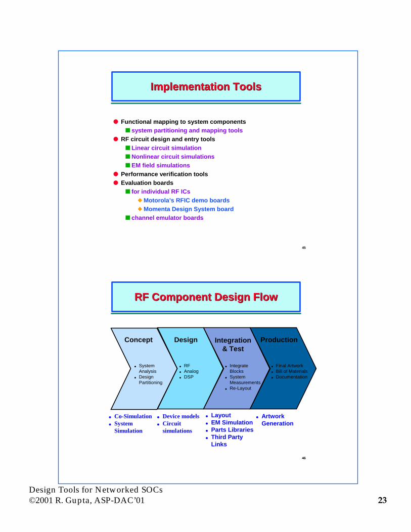
Implementation ToolsImplementation Tools
l Functional mapping to system componentsn system partitioning and mapping tools
l RF circuit design and entry toolsn Linear circuit simulationnNonlinear circuit simulationsn EM field simulations
l Performance verification toolsl Evaluation boards
n for individual RF ICsuMotorola’s RFIC demo boardsuMomenta Design System board
n channel emulator boards
46
RF Component Design FlowRF Component Design Flow
Concept Design Integration& Test
Production
l SystemAnalysis
l DesignPartitioning
l RFl Analogl DSP
l IntegrateBlocks
l SystemMeasurements
l Re-Layout
l Final Artworkl Bill of Materialsl Documentation
l Co-Simulationl System
Simulation
l Layoutl EM Simulationl Parts Librariesl Third Party
Links
l ArtworkGeneration
l Device modelsl Circuit
simulations

Design Tools for Networked SOCs©2001 R. Gupta, ASP-DAC’01 24
47
Circuit SimulatorsCircuit Simulators
l SPICEn a time domain simulatorn time step chosen for the highest frequency component in
the signaln long runtimesn can not handle frequency domain models
l Digitally modulated RF signals are narrow-band signals athigh carrier frequenciesn Spectral decomposition is not sufficiently accurate for
system performance analysis (e.g., BER)
48
RF+BB Circuit SimulationsRF+BB Circuit Simulations
l Four approachesnHarmonic balance
u use decomposition of modulated signalsu steady state view of the systemu used in ADS
n Periodic steady state analysisu used in SpectreRF
n Envelope transient analysisu replace differential equations by algebraic equationsuwaveform envelope computation with numerical
integrationuwhile carrier signals are computed with Harmonic
balancenBlock processing
u alternate between frequency and time domainthrough transformations

Design Tools for Networked SOCs©2001 R. Gupta, ASP-DAC’01 25
49
Mixed Signal SimulatorsMixed Signal Simulators
l Analog+Digitaln single kernel that combines both digital and analog
simulations on a common backplaneu ATTSIM (Verilog, VHDL and SPICE, behavioral C
code)uMentor Graphics: QuickHDL + Eldo (AnaCad) SPICE
n “third party” simulation backplaneu SimMatrix from Precedence
l RF+BBn EESof’s Circuit Envelope
u handles signal’s amplitude and phase modulationinformation in time domain
uRF carriers and harmonics in frequency domainusing s-parameter data instead of lumped models.
nCadence’s SpectreRF
50
Putting It TogetherPutting It Together
To D/A
A/DBaseband DSP
I
Q
FrequencySynthes izer90
A/D
D/AAGC
From Synthesizer
Receiver Block
Circuit Envelope SimulationTransient SimulationHP Ptolemy Simulation

Design Tools for Networked SOCs©2001 R. Gupta, ASP-DAC’01 26
51
SummarySummary
l Design tools offerings for on-chip networked and wirelesssystems are an area of growing importance due to inherentcomplexity of on-chip design and multi-level tradeoffs
l Wireless system design tools are strongly influenced by thelayer at which the design is being done
l System modeling tools are quite common and advanced
l Design environments, circuit design tools lag significantlybehind the design practice
l At the physical level, the focus is on accurate on-chipmodeling of parasitic effects.
52
ReferencesReferences
l Models of computation:n http://ptolemy.eecs.berkeley.edu
l Language and methodology :n SpecC: http://www.ics.uci.edu/~speccn OCAPI: http://www.imec.be/ocapi
l Languages :n SystemC: http://www.systemc.orgn CynApps: http://www.cynapps.comn CoWare: http://www.coware.comn Objective VHDL:
l Language semantics:n R. Gupta and S. Liao, Using a programming language for digital system
design, IEEE D&T April-June 97l Interface based design:
n Alberto DAC97 Paperl VSIA system level design workgroup: http://www.vsi.orgl System level issue: Gajski’s silicon compilation and blue booksl Software design pattern bookl Architecture description language: www.ics.uci.edu/~aces/expression