Geothermal Energy Utilization in Low-Enthalpy Sedimentary ...
POWER GENERATION
FROM HIGH ENTHALPY GEOTHERMAL RESOURCES
by Dr. Einar Tjörvi Elíasson ABSTRACT
In this presentation I shall address high temperature (high enthalpy) development, concentrating on electric power production. We live in a modern world, however, where awareness of the environment is ever on the increase. This is clearly manifest in greater demands being made of the engineer, the scientist and the developer to observe care in power development, which is by many considered the main culprit and contributor of pollution both liquid and gaseous. I will therefore touch upon integrated energy development, both because it is very close to my heart and it meets the aforesaid demands most admirably.
The task I was given is quite complex and demanding – I can thus only execute it in outline and will undoubtedly leave out many aspects that are important to some and address aspects that are of less importance to others.
One of the drawbacks are a lack of good comprehensive references which I regret.
1. SOME BASIC DEFINITIONSBefore dwelving any deeper into the utilisation of high enthalpy (temperature) geothermal resources it is important to define a few of the basic terms used in this presentation to categorise the resource. High temperature fluid temperature in excess of 250°C Medium temperature fluid temperature between 150°C & 250°C Boiling low temperature fluid temperature between 100°C & 150°C Low temperature fluid temperature between 50°C and 100°CThese are not the scientific definitions normally used but rather more practical engineering terms. Other more specific definitions are defined as they appear.
2. DEVELOPMENT STRATEGIES
Very early on the road to geothermal development, a basic strategy needs to be thoroughly studied and agreed. Such strategy strongly affects future exploration, feasibility, financing, design and construction work. Three basic strategies prevail in the world today:
A) Tailored development – electric power and industrial use:
The development is tailored to the 30-50 year yield of the reservoir that has been estimated using volumetric methods. Examples are Lardarello, Wairakei, the Geysers, Tiwi, Cerro Prieto Ahuachapan, Hatchubaru, and Olkaria.
This type of tailored development was conventional during the early years of geothermal development which was heavily biased towards electricity production. The plant output was decided on the basis of an estimated reservoir volume, average formation temperature, and porosity. Usually lead to overestimate of yield and useful life span.
Main advantages: • Maximum size of development steps • Benefits of scale i.e. lower cost per unit installed power • Larger initial power capacity widens choice of markets
Main disadvantages: • Large initial capital investment required • Long development time • Under capacity operation reduced earnings • Serious reservoir depletion problems • Less operating security
A study carried out in Iceland and reported at a five-annual Energy Congress held in Iceland 1991 by Valgardur Stefánsson, Benedikt Steingrímsson and E.T. Eliasson found that the
291
standard volumetric reservoir capacity methods predicted capacities three to four times greater than methods using reservoir simulation techniques.
ADVICE: IN CONTEMPLATING DEVELOPMENTS TAILORED TO A RESERVOIR CAPACITY, BE VERY CAREFUL IN ADOPTING A CAPACITY BASE ARRIVED AT SOLELY BY VOLUMETRIC ASSESSMENT.
B) Stepwise development – electric power and thermal energy production:
The reservoir is developed in 10–30 MW steps with a 2-3 year interval between each development step during which time you study the reservoir response etc. for the next step. This new idea, which first was put forward by Dr. V. Stefansson in 1990, has now been adopted in Iceland.
The development is divided into several manageable steps, and often more than one geothermal field may be under parallel development at the one time. The step size is decided on basis of local specifics such as needs of local energy market, economic minimum size, preliminary assessment of reservoir capacity etc.
The basic idea is that each step be only a portion of the pre-assessed reservoir capacity using for instance volumetric assessment methods.
Main advantages:Development can be made to suit available finances • Earnings start early • Minimun initial investment • Better possibility for low environmental impact • Investigate as you developDisadvantages:Smaller development units reduces size
benefits • Development spread to more than one area at the one time to ensure high rate of
development
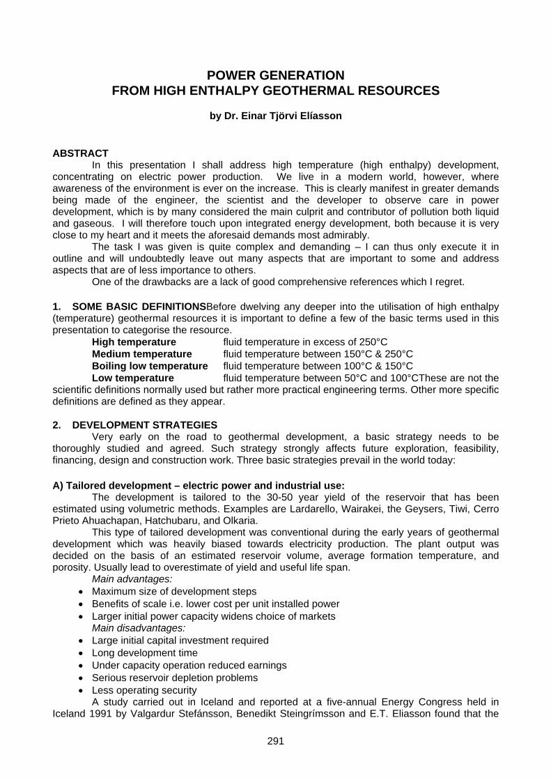
C) Integrated development – multi-use applications: The reservoir is developed for multiple use right from the start. This strategy was
pioneered in Svartsengi 1976 and is widely adopted in Iceland.
Figure 1: Húsavík energy development
Integrated development ensures the best o/a conversion efficiency, typically the highest earnings per kWh from the development and also the minimum gaseous emission into the atmosphere per produced kWh. Figure 1 shows development of a multiple use boiling low temperature source.
292

Figure 2: Nesjavellir energy
development
Figure 3: Production diagram for the newest Svartsengi Energy Facility (OV-5) Figure 2 shows a combined heat and power development, producing electricity combined
with steam to heat fresh water for district heating. The source is a high temperature resource and the output is currently some 60 MWe and 150 MWt.Figure 3. on the other hand depicts a very
293

interesting CPH solution adopted in the year 2000 for the new addition to the Svartsengi Plant. It features an energy system that is new in geothermal development though it is well tried in the chemical and divers process industries. Instead of deploying a backpressure turbine as is quite common, steam is here tapped off the turbine at two points and used with cooling water from the condenser as the energy source for the cascated uses to improve overall efficiency of conversion.
3. ENERGY CONVERSION SYSTEMS
High temperature developments of this type comprise five basic subsystem components: 1. Steam/fluid supply 2. Energy and/or power production 3. Effluent disposal 4. Energy and/or power transmission or distribution 5. Control systems
1. The steam/fluid supply subsystem comprises: • Geothermal wells complete with mufflers and control valves • Fluid collection pipelines, flash/separator units, steam mains and vapour eliminators2.
Energy and/or power production subsystem comprises of: • Power turbine/generator units • Condensing facility and/or heat exchanger banks and pumping units • Control systems • Monitoring systems
3. Effluent disposal subsystem comprises of: • Gas evacuation and gas disposal facility • Liquid effluent collection and disposal • Control systems • Monitoring systems
4. Energy/power transmission or distribution subsystem comprises: • Electrical power transformers • High tension power lines and switch gear • Steam or hot water transmission pipelines and pumping plant • Pressure control and/supply compensation tanks
5. Control subsystem comprises of: Miscellaneous automatic and computer aided system controls frequently remote. In the following it will be endeavoured to outline each of these conversion components,
the problems and some of the aspects that have to be considered to arrive at an acceptable solution.
4. HIGH TEMPERATURE WELLS
They are typically drilled in four stages: • A wide hole to a depth of 50-100 m into which is cemented the surface casing. • A narrower hole to a depth of 200-600 m into which the anchor casing is cemented • A narrower hole still to a depth of 600 to 1.200 m which carries a cemented casing called
the production casing • Finally the production part of the well is drilled into and/or through the active aquifer. This
part carries a perforated liner that is hung from the production casing reaching almost to the well bottom. On top (wellhead) the well is fitted with expansion provisions and a sturdy sliding plate
valve (master valve). It is also connected to a muffler, usually of a steel cylinder fitted with an expanding steam inlet pipe to slow down the fluid on entry. Steam capacity of these wells commonly range between 3-30 kg/s (1,5 MWe -15 MWe).
The wells are often enclosed in a lightweight enclosure to keep the wellhead warm, free from dirt and curious visitors both animal and human.
4.1 Typical wells types
Geothermal wells are in principle either straight or directional. The drilling programs are of two types:
294
A) Standard: Surface casing 18” nominal diameter in a 20” hole Anchor casing 13 3/8” nominal diameter in a 17 ½” hole Production casing 9 5/8” nominal diameter in a 12 ½” hole Liner 7” nominal diameter in a 8 ½” hole.
B) Wide: Surface casing 22” nominal diameter in a 24” hole Anchor casing 18” nominal diameter in a 20” hole Production casing 13 3/8” nominal diameter in a 17 ½” hole Liner 9 5/8 nominal diameter in a 12 ½” hole
The wide configuration may give as much as twice the yield of a standard one for the same formation resistance
4.2 Typical well casing programme
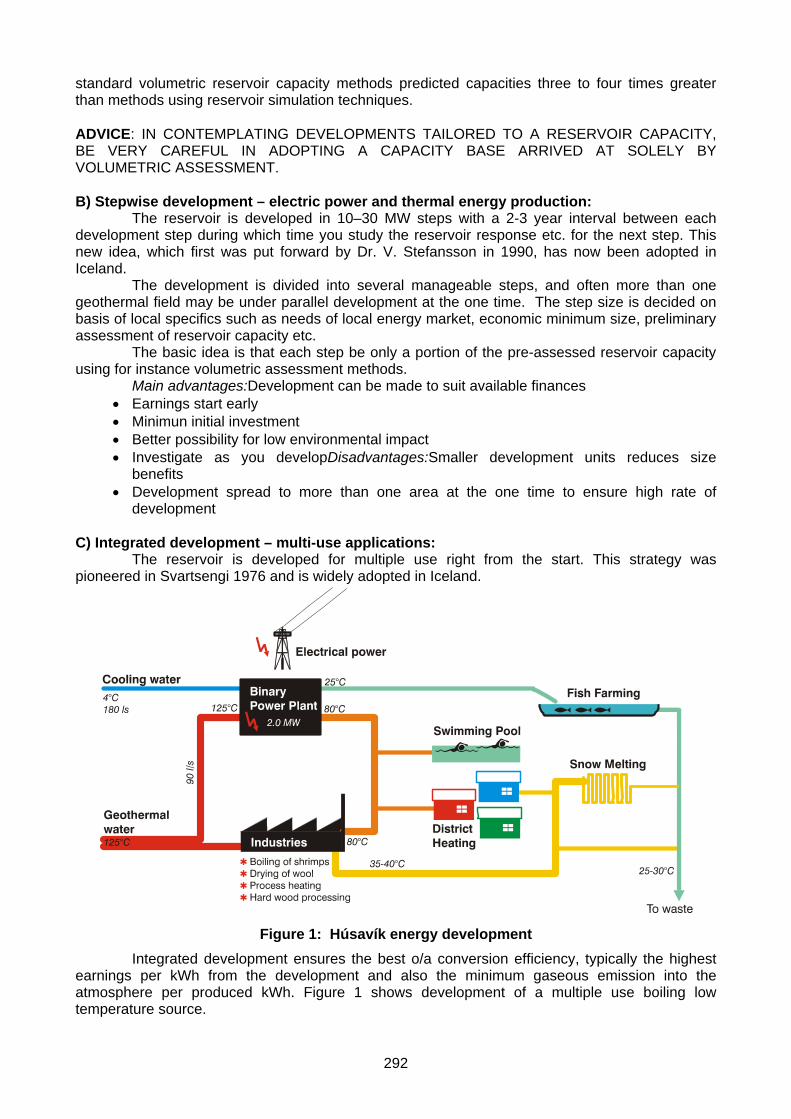
The types of well casings, which are all cemented to the formations, are depicted on Figure 4. They have the following denotations:
6. Conductor 7. Surface casing 8. Intermediate or anchor casing 9. Production casing.
Figure 4: Casing types In addition to those there is the production liner, which is slotted/perforated and not
cemented to the formations but hung from a special casing hanger usually placed some 20 m or so from the shoe (bottom) of the production casing. The liner ends some 20 – 30 m abobe the bottom of the well to allow for thermal expansion.
The functions of the casings and liner are basically as follows:
•Conductor
•Surface Casing
•Intermediate Casing
• Production Casing
•Slotted liner
•Conductor
•Surface Casing
•Intermediate Casing
• Production Casing
•Slotted liner
• Conductor and surface casing are used to facilitate drilling through unconsolidated surface formations.
• The intermediate or anchor casing prevents breakthrough of steam up through the surface during drilling, protecting rig and crew.
• The production casing closes off cold aquifers and provides a conduit for the fluid up the well.
•• The liner is not cemented and prevents the well wall from collapsing into the well during operation.
4.3 Typical liner perforations As previously recounted, the liner is perforated or slotted. Thorough studies carried out in
Iceland and elsewhere indicate that the degree of perforation needed to ensure adequate flow area without undue restriction to inflow corresponds to some 3% to 6% of the surface area of the liner.
In other words the periferal slot/perforation area per meter of liner is usually kept within this range. Another factor that affects the choice of the actual number of slots per meter of casing is the weakening of the liner’s tensile strength caused by the slots. The longer the liner the lower
295
must be the ratio. Axial staggering of the slots should also be considered to minimise nonuniformity of strength along the liner’s length.
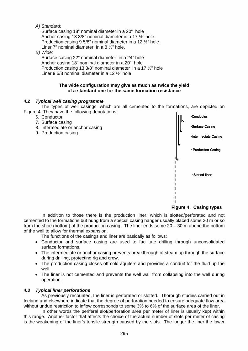
The basic shapes and mode of perforating the liner and depicted in Figure 5. is: • Rectangular slots
flame cut or milled • Oval shaped slots
flame cut • Rectangular inclined slots
flame cut or milled • Circular holes
drilled, flame cut, shot
Figure 5: Typical liner slots
4.4 Boiling point with depth
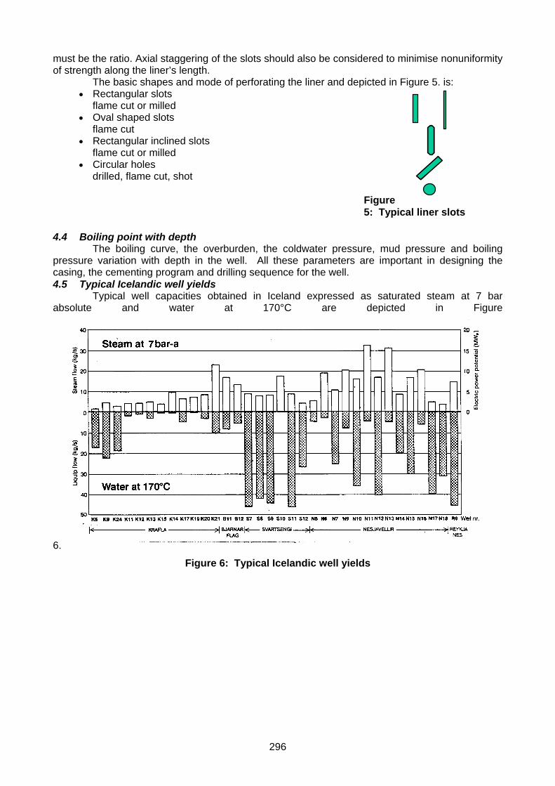
The boiling curve, the overburden, the coldwater pressure, mud pressure and boiling pressure variation with depth in the well. All these parameters are important in designing the casing, the cementing program and drilling sequence for the well. 4.5 Typical Icelandic well yields
Typical well capacities obtained in Iceland expressed as saturated steam at 7 bar absolute and water at 170°C are depicted in Figure
6. Figure 6: Typical Icelandic well yields
296

5. SCALING IN GEOTHERMALThe type of deposition (scaling) most commonly encountered in surface equipment are those of silica, sulphite and calcite.
Figure 7: Solubility of silica
The diagram in Figure 7 shows how the solubility of silica in water varies with temperature and the degree of boiling.
Deposition of silica is a common occurrence in high temperature geothermal systems. It is therefore important to realise the disposition potential at various sensitive points of the conversion system so that appropriate and timely measures can be taken to alleviate and/or side-step deleterious effects.Silica scaling has a time factor that is temperature and salinity dependent and can be made to work in ones favour, i.e. it can be used to delay the onset of scaling and thus select the place where in the system the scaling takes place.Surface pipeline to be cleaned of calcite scaling by the use of high pressure jet washing technique is depicted on Figure 8. This shows the condition of the steam collection pipe some 50 m after the well in the Reykjanes field. The pipeline requires cleaning about once every four years. See also calcite scaling in a well liner Figure 9.
Figure 8: Calcite scaling in surface pipes
297

Figure 9. Calcite scaling in Krafla well liners
Calcite, as said before, is deposited largely through carbon dioxide coming out of solution in fluids that are rich in calcium. Calcite does, however, have reverse solubility, which means the solubility is increased as the temperature falls. It is therefore always preferable to keep the CO2 gas in solution in heat exchange situations and remove first after the heat exchanger when the fluid has cooled down. 6. STEAM FLASH/SEPARATORS
Steam is separated from the geothermal fluid using the forced vortex principle. The fluid is introduced into a cylinder via a tangential or a streamlined inlet. Two basic designs are in use; based either on a vertical or a horizontal separator vessel.
• The former admits the fluid via a streamlined inlet and is fitted with a central vertical pipe for tapping of the steam whereas the liquid fraction is discharged radially low on the vessel’s body via an orifice arrangement. The steam and liquid phases separate mainly via centrifugal action.
• The latter admits the fluid via a tangential inlet into a wide horizontal vessel fitted with a curved horizontal vane and a droplet filter in front of the steam outlet port. The separation is chiefly through gravity effects. The liquid discharge is tangential low on the vessel’s body via an orifice as before. Separation efficiency is very important because all dissolved solids carried over as
droplets from the separator result in scale deposition in the attached energy conversion system such as on turbine vanes/blades, in heat exchanger tubing etc.
All separators constructed and installed in Iceland 1967-1995 were of the vertical design, the horizontal type fitted with droplet elimination mats gaining popularity after in later years.
Mist eliminators are generally installed in the steam mains just before it enters the building. Steam traps are also fitted to long steam mains to tap of condensate.
Vertical separator design Advantages:
• Sharper cut-off • Cleaner steam • Wider pressure range • Maintenance easy
Disadvantages: • Size limitations • Height of construction
Horizontal separator design Advantages:
• Size not a constraint • Greater throughput/unit
Disadvantages: • Needs mist eliminators to ensure good quality steam • Greater maintenance • Generally less expensiveSteam drynness needs to be kept better than 99,995% to ensure
low scaling rate in equipment. Steam quality is highly sensitive to control of liquid level in separators, more so the vertical design.
298
0 2 4 6 8 10 120
2
4
6
8
10
12
14
16
18
20
ORKUSTOFNUN ROSS. Þórh. 27.03.1999
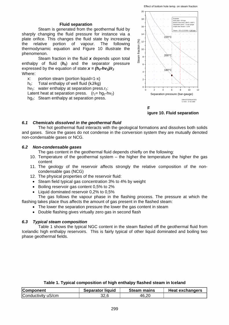
Example:Well yield = 30 kg/sBottom hole temp. (BHT) =180°CSeparation press. = 6 bar gaugeGraph then shows = 3,2%
Steam = 30 x (3,2/100) = 0,96 kg/s
Effect of bottom hole temp. on steam fraction
220°C
200°C
180°C
Ste
am fr
actio
n (%
)
Separation pressure (bar-gauge)
Fluid separation Steam is generated from the geothermal fluid by
sharply changing the fluid pressure for instance via a plate orifice. This changes the fluid state by increasing the relative portion of vapour. The following thermodynamic equation and Figure 10 illustrate the phenomenon.
Steam fraction in the fluid x depends upon total enthalpy of fluid (h0) and the separator pressure expressed by the equation of state:x = (h0-hv2)/r2Where:
x: portion steam (portion liquid=1-x) h0: Total enthalpy of well fluid (kJ/kg) hv2: water enthalpy at separation press.r2: Latent heat at separation press. (r2= hg2-hv2) hg2: Steam enthalpy at separation press.
Figure 10. Fluid separation
6.1 Chemicals dissolved in the geothermal fluid
The hot geothermal fluid interacts with the geological formations and dissolves both solids and gases. Since the gases do not condense in the conversion system they are mutually denoted non-condensable gases or NCG.
6.2 Non-condensable gases
The gas content in the geothermal fluid depends chiefly on the following: 10. Temperature of the geothermal system – the higher the temperature the higher the gas
content 11. The geology of the reservoir affects strongly the relative composition of the non-
condensable gas (NCG) 12. The physical properties of the reservoir fluid: • Steam field typical gas concentration 3% to 4% by weight • Boiling reservoir gas content 0,5% to 2% • Liquid dominated reservoir 0,2% to 0,5%
The gas follows the vapour phase in the flashing process. The pressure at which the flashing takes place thus affects the amount of gas present in the flashed steam:
• The lower the separation pressure the lower the gas content in steam • Double flashing gives virtually zero gas in second flash
6.3 Typical steam composition
Table 1 shows the typical NGC content in the steam flashed off the geothermal fluid from Icelandic high enthalpy reservoirs. This is fairly typical of other liquid dominated and boiling two phase geothermal fields.
Table 1. Typical composition of high enthalpy flashed steam in Iceland Component Separator liquid Steam mains Heat exchangers Conductivity uS/cm 32,6 46,20
299

Silicate (SiO2) 869 0,60 0,70 Sodium (Na) 12.587 0,09 1,39 Potassium (K) 1.905 0,21 0,67 Magnesium (Mg) 1,16 0,03 0,02 Calsium (Ca) 2.263 0,35 0,69 Chloride (Cl) 25.030 0,94 2,34 Sulphate (SO4) 36,4 1,07 1,61 Iron (Fe) 0,47 0,02 0,02 Total dissolved solids (TDS) 45.120 4,60 6,20
The solids content and composition is more varied, however, particularly as regards chloride and divers trace elements, some of which may be highly polluting, e.g. Boron, Fluoride, Mercury, etc. Geothermal fluids containing as much as 130 g/kg (130.000 ppm), mostly sodium chloride, are known. In Iceland the maximum TDS is about 30 g/kg (30.000 ppm) in the Svartsengi field. 7. FLASHED STEAM SYSTEMS
Flashed steam is most common in all types of geothermal energy conversion systems whatever their type, such as with: A) Back pressure units – common as well-generation-
units also used in integrated CPH type geothermal plants. B) Flash steam electric power condensing turbine generator units – single flash/double flash. C) Hybrid electric power plants – flash plant combined with binary. D) Binary units - most commonly in difficult fluid chemistry environments. The binary converter is
adopted for many reasons the most significant ones being: a) to isolate chemistry related problems such as from high TDS b) simplicity of operation c) Method well tried and established
7.1.1 Hybrid systems
Commonly constitute combined backpressure unit and binary unit in cascade. Sometimes also condensing steam plant in parallel with a binary plant. Hybrid plants potentially have greater conversion efficiency than its conventional flashed steam condensing or pure binary equivalent.
Hybrid energy conversion systems are particularly suited to medium temperature geothermal resources where the fluid properties are not unduly difficult. 7.1.2 Binary energy converters
Purely binary systems come best to their own right in the utilisation of: • boiling low temperature reservoirs for electricity production • in harnessing geothermal resources of very high TDS and difficult chemical compositions
It must be realised, however, that a purely binary plant is a low efficiency conversion equipment that is therefore best used in cascade in a multi-use or hybrid type situation in a way that benefits the o/a efficiency of utilisation.
There are two distinct systems of the binary type on the market: • The Organic Rankine Cycle type energy converter commonly called the ORMAT type
energy converter after the company that has been in the forefront of its commercial development. Available from:
• ORMAT Industries Ltd of Israel • TURBODEN Ltd of Italy • Mitsubishi Heavy Industries Ltd and others from Japan • The Kalina Cycle named after its inventor prof. Kalina. It is available from: • Exergy Inc. Of California, USA
Of the two binary converter types the latter is more efficient within the temperature ranges featured in this discourse but also more complex.
The binary conversion system is based upon a two fluid system, where the geothermal fluid is the primary energy source and transfers thermal energy via heat exchangers to a second low boiling point fluid in a closed system. The second fluid, normally one of the carbon hydrates (butane or pentane), in turn drives the turbine generator. From the heat exchangers the geothermal fluid is disposed of and often returned back to the reservoir.
300

8. CONDENSING PLANT
The greatest preponderance of high and medium temperature areas are found in relatively arid locations or where cold surface water is scarce. The most commonly adopted condensing systems in geothermal are thus the so called jet condensers coupled with forced ventilation cooling towers. The NCG is exhausted from the condenser either via steam ejectors (NCG<2%-3% of steam by weight) or by mechanical means using mischellaneous vacuum pumps (often liquid ring extractors). The cooling cycle is usually “closed”, the condensed water is circulated through the cooling tower and sprayed into the condenser.
Mechanical problems: • Cooling tower fill • Icing • Fouling
Chemical problems: • Sulphur deposition • Corrosion due to low pH and oxygen
Other problems: • Bacteria growth • Flaking of pond walls • Disposal of NCG exhausted
9. CHEMISTRY SPECIFICSThe most commonly encountered chemical type problems in geothermal development are:
• High non-condensable gas contents • High total dissolved solids (TDS) contents • Difficult chemical compositions
They affect the operating part of a geothermal utilisation system, the gaseous effluent disposal and liquid effluent disposal e.g. via re-injection.
9.1 High NCG contentThe most commonly encountered problems with regard to high gas content in the geothermal steam are:
• To meet legislative pollution criteria as regards atmospheric pollution High NCG content tend to lower conversion efficiency particularly as regards the evacuation of condensing plant and heat exchanger equipmentHigh H2S content generally promotes metallurgical problems such as corrosion, stress corrosion cracking and metal fatigueHigh CO2 content in geothermal fluid below about 200°C accelerates calcite scaling and may promote corrosion.
9.2 High TDS content in fluid High content of dissolved solids causes numerous problems. The most serious of these
are various types of solids disposition problems that plug up flow conduits. Table 2 shows the type of chemical composition that may be encountered in the fluids in
energy conversion circuitry. The fluid in question is from a high TDS field in Iceland.
Table 2: Example of chemical composition of fluid in conversion system High pressure reservoir Pressure (bar a) H2O % CO2 % H2S % Reykjanes 10,0 99,30 0,672 0,019 Svartsengi 5,5 99,80 0,196 0,003 Hveragerdi 5,5 99,84 0,138 0,006 Bjarnarflag 11,0 99,70 0,060 0,060 Krafla 8,0 98,70 1,140 0,070
10. RE-INJECTION OF FLUID AFTER USE
Re-injection of the geothermal liquid used back into the reservoir has a number of purposes, the most important ones being:
• Disposal of the used liquid without polluting the environment • Sustenance of the reservoir pressure to counteract draw down and surface subsidence
301
• Mining of heat stored in the hot formations simultaneously extending the useful life of the reservoirThe associated problems are mainly:
• Chemical deposition of silicates • Loss of injectivity due to properties of formations injected into, particular in the case of
sandstone • Coldwater breakthrough from injection wells to production wellsMany different methods
are used to overcome the deposition problem. They depend upon the type of deposition encountered, the geological situation and the economic environs. The more important ones are:(i) Calcite deposition:
• Thermodynamic countermeasures coupled using the reverse solubility characteristics of calcite coupled with keeping the CO2 in solution until the under saturated state is reached
• Introduction of calcite scaling inhibitor chemicals into re-injected fluid(ii) Silicate deposition:
• Keeping the re-injected fluid at a temperature above the silica deposition point and keep out of contact with atmospheric air
• Control the pH of the re-injected mixture using plant condensate and/or acidification • Use scale inhibitor admixtures in effluent liquid • Promote polymerisation of silica in the effluent liquid and letting it settle out in special
settling ponds prior to re-injection • Treatment with special acid admixes with additives to protect casing (iii) Re-injecting into
sandstone: • Superfine filtration of effluent combined with friction reducers • Periodic reversals of injection well • Ream-out of injection zone of well to increase injection area
(iv) Location of injection wells to avoid coldwater breakthrough: • Depth at which to inject effluent • Policy of re-injection at circumference of production area • Do careful injectivity tests and chemical tracer tests to determine production/injection well
distance that ensures a breakthrough time commensurate with acceptable reservoir life, if re-injecting within production area.
11. OTHER LOCALITY SPECIFICS AFFECTING TECHNOLOGICAL SOLUTIONS The important ones are:
11.1 Environmental issuesThese are gaining importance and seriously affect the feasible solutions that can be adopted. Issues like:
• Effluent disposal - gaseous as well as liquid • Selection of sites for wells, collection pipelines, access roads, mufflers, power
transmission line sites, mast types etc • Noise criteria – short and long-term • Tourism
11.2 Accessibility
• Topography at development site • Access to water – climatic conditions • Proximity to centres of population
11.3 Local technological status
• Access to technological competence locally, regionally, nationally
11.4 Energy market • Type, versatility and stability of energy market
11.5 Political constraints
• Is geothermal part of national energy plan? • Financial, taxation and legislative constraints
302

Geothermal fluid has a low specific energy content and all solutions adopted for its
utilisation must be simple and inexpensive. It also sometimes has chemical problems associated with it that preclude the use of high
tech refinements. The hydrogen sulphide in the steam phase, though quite insignificant for all sense and purpose, is quite sufficient to play havoc with some of the modern sensors, control equipment and computer systems which means that highly special and often costly equipment is required to ensure the required degree of reliability.
Material selection for the parts in direct contact with the geothermal fluid is also quite important.
USEFUL REFERENCES
1. Geothermal Energy Utilization. Edward F. Wahl; 1977, ISBN 0-471-02304-3. 2. Handbook of Geothermal Energy. Editors L. M. Edwards et al; 1982, ISBN 0-87201-322-7. 3. Geothermal Energy. Editors M. H. Dickson, Mario Fanelli; 1995, ISBN 0 471 95366-0. 4. Code of Practice for DEEP GEOTHERMAL WELLS (NZS 2403:1991): Table of contents: 1. General 2. Well Design 3. Well Sites 4. Drilling Equipment, Tools and Materials 5. Drilling Practices 6. Operation and Maintenance of Wells 7. Abandonment of Wells
303