Power Clamp Cylinder Series CKZT - smc.nu · Features 2 3D CAD Software CATIA UNIGRAPHICS FIDES...
20
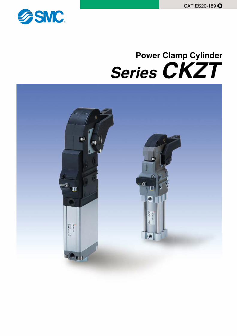
CAT.ES20-189 A Series CKZT Power Clamp Cylinder
Transcript of Power Clamp Cylinder Series CKZT - smc.nu · Features 2 3D CAD Software CATIA UNIGRAPHICS FIDES...
CAT.ES20-189 A
Series CKZTPower Clamp Cylinder
CKZT.qxd 05.11.11 9:44 AM Page 1
Features 1
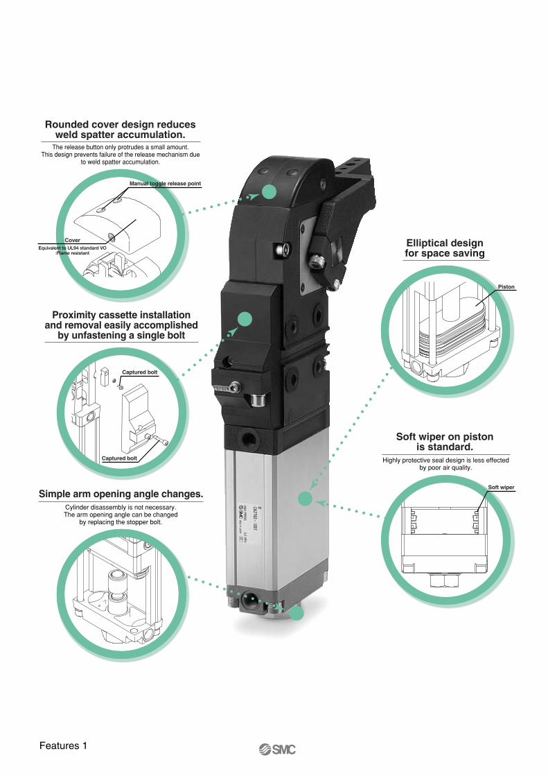
Simple arm opening angle changes.
Rounded cover design reducesweld spatter accumulation.
Manual toggle release point
Cover Elliptical designfor space saving
Soft wiper on pistonis standard.
Soft wiper
Proximity cassette installationand removal easily accomplished
by unfastening a single bolt
Captured bolt
Captured bolt
Piston
CKZT.qxd 05.11.11 9:44 AM Page 2

Features 2
3D CAD
Software
CATIA
UNIGRAPHICS
FIDES
AUTO CAD
SOLID WORKS
∗ For additional formats please log on to the SMC web site www.smcusa.com and click on the E-Tech icon.
Series Variations
Series
Bore size (mm)
Arm openingangle
Switch
Port thread type
ø50Equivalentø40 ø63
Equivalent
30°, 45°, 60°, 75°90°, 105°, 120°, 135°
TURCK/P&F
G/NPT
ø80Equivalent
CKZT
Toggle link mechanism
Proximity switch
External stopper
Seal
ArmBumper
Fulcrum stopper
Seal (Equivalent to UL94 standard VO Flame resistant)
CKZT.qxd 05.11.11 9:44 AM Page 3

Power Clamp Cylinder
Series CKZTø40, ø50, ø63, ø80
1
How to Order
CKZT TN63 120 T
Power clamp cylinderEuropean type
Bore size40506380
ø40ø50ø63ø80
Cylinder portNilTN
GNPT
3045607590
105120135
30°45°60°75°90°
105°120°135°
Switch type
Arm opening angle
TP
TurckP & F
CKZT 40 A015 C
A015A045
Offset 15Offset 45
Arm position
Offset
R
Right
C
Center
L
Left
S
Power clamp cylinderEuropean type
Bore size
Mounting hole
40 ø40
SB
H1620
D2
710.2
D1
68
∗
H
øD1 øD2
H
øD1 øD2
øD1
H
øD2
∗ For A015, S type only
Clamp Cylinder Without Arm
Clamp Arm (40)
CKZT.qxd 05.11.11 9:44 AM Page 4

2
Power Clamp Cylinder Series CKZT
CKZT 63 A015 C
A015A045
Offset 15Offset 45
Arm position
Offset
R
Right
C
Center
L
Left
øD1 øD2
øD1 øD2
S
Power clamp cylinderEuropean type
Bore size
Mounting hole
506380
ø50ø63ø80
SB
D2
910.2
D1
68
øD1 øD2
Clamp Cylinder (50, 63, 80)
CKZT.qxd 05.11.11 9:44 AM Page 5

3
Series CKZT
Cylinder Specifications
Bore size (mm)
Double acting
Air
1.2 MPa (174 psi)
0.8 MPa (116 psi)
0.3 MPa (44 psi)
–10 to 60°C (14 to 140°F)
Clamping side: None Unclamping side: Rubber bumper
1.0 second to clamp, 1.0 second to unclamp
Action
Fluid
Proof pressure
Max. operating pressure
Min. operating pressure
Ambient and fluid temperature
Cushion
Min. operating time
40 50 63 80
Weight (Cylinder Without Arm)
Note) Switch specifications are correspondling to manufacturer’s technical information.
Switch Specifications
Manufacturer
2 mm ± 10%
10 to 30 VDC
N.O., PNP
�150 mA
30 Hz
PBT-GP30
Clamping side: Red Unclamping side: Yellow
Green
2 mm ± 10%
10 to 30 VDC
N.O., PNP
�100 mA
25 Hz
PA6, PBT
Clamping side: Red Unclamping side: Yellow
Green
Operating range
Supply voltage
Output
Continuous load current
Response frequency
Housing material
Output indication
Voltage indication
TURCK P & F
Wiring Diagram
Black
S2 Lood
S1 Lood
(–)
(+) Brown White
Blue
2
3
1
4
P&F
(–)
(+)
3 Blue
2 White
4 Black1 Brown
S2 Lood
S1 Lood
TURCK
Unit: kg (lbs)
Bore size (mm)
40
50
63
80
30° 45° 60° 75° 90°Arm angle
105° 120° 135° 1.57 (3.45)
5.21 (11.46)
7.37 (16.21)
17.20 (37.84)
1.57 (3.45)
5.19 (11.42)
7.34 (16.15)
17.13 (37.69)
1.57 (3.45)
5.17 (11.37)
7.31 (16.08)
17.07 (37.55)
1.57 (3.45)
5.15 (11.33)
7.28 (16.02)
17.00 (37.40)
1.56 (3.43)
5.12 (11.26)
7.24 (15.93)
16.93 (37.25)
1.56 (3.43)
5.09 (11.20)
7.21 (15.86)
16.86 (37.09)
1.56 (3.43)
5.07 (11.15)
7.18 (15.80)
16.80 (36.96)
1.56 (3.43)
5.06 (11.13)
7.16 (15.75)
16.76 (36.87)
CKZT.qxd 05.11.11 9:44 AM Page 6

Construction (40)
t
!2
u
!0
o
q
e
y
i
w
r
!1
A A
A-A
Replaceable Kits List Table 1
Switch cassette
Parts for changingopening angle of arm
Note 1) T: TURCK, P: P&FNote 2) Please specify the opening angle by the code in Table 1.
40 CKZT-T040
CKZT-K040∗ (See Note 2)CKZT-D040∗CKZT-B040∗
!1 Seal washer!5 Seal washer
r Bumperw Stopper bolt
40
CKZT-D040∗ (See Note 2)
40 CKZT-S040 (See Note 1)
!2 Cover cap screw
!0 Short head cap screwo Spring washer
i Sheet gasketu Parallel pin
q Stay
y Inductive switche Switch holder
ContentsKit no.BoreDescription
CKZT-B040∗ (See Note 2)!1 O ringr Bumperw Stopper bolt
CodeOpening angle
H
G
F
E
D
C
B
A
30°45°60°75°90°
105°120°135°
TP
!3!5 !4
Top cover kits
4
Power Clamp Cylinder Series CKZT
CKZT.qxd 05.11.11 9:44 AM Page 7

Construction (50, 63, 80)
t
!2
u!0oqe
y
i
wr
!1
!3!4
Replaceable Kits List Table 1
Top cover kits
Switch cassette
8063
50
CKZ2N-T080
CKZ2N-T063
CKZ2N-T050
80CKZN-B080∗ (See Note 2)
CKZN-D080∗ (See Note 2)
!1 Seal washer
!0 Socket head cap screwo Spring washer
r Bumperw Stopper bolt
!4 Short head cap screw!3 Spacert Top cover
q Switch actuator
63CKZN-B063∗ (See Note 2)
CKZN-D063∗ (See Note 2)
CKZN-K050∗ (See Note 2)CKZ1N-D050∗CKZN-B050∗
CKZN-K063∗ (See Note 2)CKZ1N-D063∗CKZN-B063∗
CKZN-K080∗ (See Note 2)CKZ1N-D080∗CKZN-B080∗
!1 Seal washer
!0 Short head cap screwo Spring washer
r Bumperw Stopper bolt
q Switch actuator
50CKZN-B050∗ (See Note 2)
CKZN-D050∗ (See Note 2)
80
63
50
Note 1) T: TURCK, P: P&FNote 2) Please specify the opening angle by the code in Table 1.
CKZ1N-S080 (See Note 1)
CKZ1N-S063 (See Note 1)
!2 Cover cap screw
!1 Seal washer
!0 Socket head cap screwo Spring washer
i Sheet gasketu Parallel pin
r Bumperw Stopper bolt
q Switch actuator
y Inductive switche Switch holderCKZ1N-S050 (See Note 1)T
P
ContentsKit no.BoreDescription CodeOpening angle
H
G
F
E
D
C
B
A
30°45°60°75°90°
105°120°135°
TP
TP
Parts for changingopening angle of arm
A-AA A
5
Series CKZT
CKZT.qxd 05.11.11 9:44 AM Page 8

Maximum Cylinder Locking Moment
40
50
63
80
380
800
1500
2500
3363
7080
13274
22124
Bore size (mm)Max. locking force
Maximum Clamping Moment
Cylinder Stroke
To determine actual clamp force.
40
50
63
80
35
100
300
560
310
885
2655
4956
76
130
350
720
673
1150
3097
6372
118
160
400
880
1044
1416
3540
7788
154
190
450
1040
1363
1681
3982
9204
178
220
500
1200
1575
1947
4425
10619
194
250
550
1360
1717
2212
4867
12035
Bore size (mm)
Max. clamping force
∗ at 0.5 MPa
N �m
0.3 MPa
Ibf � in
Ibf � in
N �m
0.4 MPa
Ibf � in N �m
0.5 MPa
Ibf � in N �m
0.6 MPa
Ibf � in N �m
0.7 MPa
Ibf � in N �m
0.8 MPa
Ibf � in
40
50
63
80
30˚ 45˚ 60˚ 75˚ 90˚ 105˚
33.3
38.9
42.5
59.4
26.8
31.1
34.1
47.3
39.6
46.4
50.5
71.1
45.9
54.1
58.6
83.2
52.3
61.9
66.8
95.7
58.4
69.6
74.7
108.0
120˚
63.6
76.4
81.5
119.1
135˚
Unit: (mm)
67.3
81.3
86.3
127.3
Bore size
N �m
Angle
Example: CKZT50, 0.5 MPa, distance from pivot to clamping point = 100 mm (3.937 in.)
N= = =N·m (from chart) x 1000
Distance from pivot to clamping point (mm)
160 N·m x 1000
100mm1600N
Ibs.= = =lbf·in (from chart)
Distance from pivot to clamping point (in.)
Verification: N = lbf
0.22481600N x 0.2248 = 359.68 lbf
1416 lbf·in
3.937 in.359.69 lbf
6
Power Clamp Cylinder Series CKZT
CKZT.qxd 05.11.11 9:44 AM Page 9

Selection Graph
30°45°60°75°90°
105°120°
15°
135°
Dis
tanc
e fr
om p
ivot
poi
nt (
mm
)
200
180
160
140
120
100
80
Load capacity (N)
0 5 10 15 20 25 30 35 40 45 50 55 60
ø50
Dis
tanc
e fr
om p
ivot
poi
nt (
mm
)
Load capacity (N)
300
280
260
240
220
200
180
160
140
120
1000 5 10 15 20 25 30 35 40 45 50 55 60 65 70 75 80
ø63 ø80D
ista
nce
from
piv
ot p
oint
(m
m)
Load capacity (N)
400
380
360
340
320
300
280
260
240
220
200
180
160
1400 5 10 15 20 25 30 3540 45 50 55 60 6570 75 80 85 90 95100 105 110 115 120 125 130 135
Dis
tanc
e fr
om p
ivot
poi
nt (
mm
)
ø40
Load capacity (N)
0 5 10 15 20 25 30
200
0
20
40
60
80
100
120
140
160
180
7
Series CKZT
CKZT.qxd 05.11.11 9:44 AM Page 10
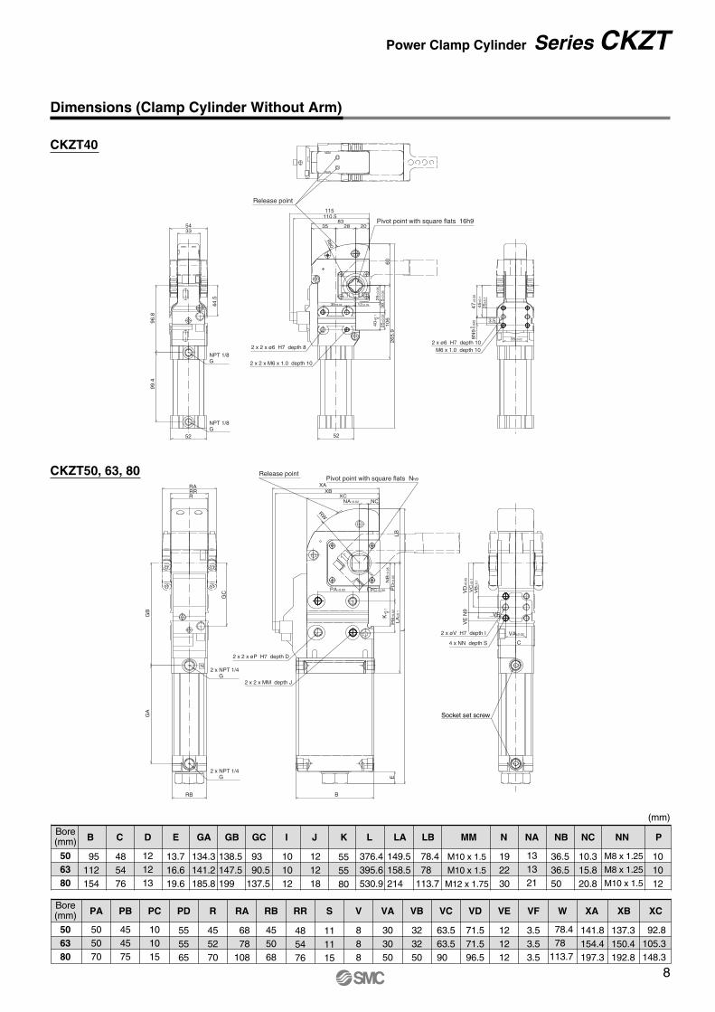
Dimensions (Clamp Cylinder Without Arm)
506380
Bore(mm)
506380
95112154
485476
121213
13.716.619.6
134.3141.2185.8
138.5147.5199
93 90.5137.5
101012
121218
555580
376.4395.6530.9
149.5158.5214
78.4 78113.7
M10 x 1.5
M10 x 1.5
M12 x 1.75
192230
131321
36.536.550
10.315.820.8
M8 x 1.25
M8 x 1.25
M10 x 1.5
101012
Bore(mm) B C D E GA GB GC I J K L LA LB MM N NA NB NC NN P
505070
454575
101015
555565
455270
68 78108
455068
485476
111115
888
303050
323250
63.563.590
78.4 78113.7
141.8154.4197.3
137.3150.4192.8
92.8105.3148.3
PA PB PC PD R RA RB RR S V VA VB VC
71.571.596.5
121212
VD VE
3.53.53.5
VF W XA XB XC
(mm)
2 x 2 x ø6 H7 depth 8
2 x 2 x M6 x 1.0 depth 10
M6 x 1.0 depth 10
52
12±0.0535±0.02
35±0.02
25
±0.0
540
+0.
10
38.5
±0.0
525
±0.0
2
10
62
65
.960
20283583
115110.5
R80
52
99.4
96.8
44.5
3354
NPT 1/8G
NPT 1/8G
3.5
47±0
.05
45
±0.1
25
±0.1
08
N9
-0.0
43
2 x ø6 H7 depth 10
Pivot point with square flats 16h9
Release point
XCXB
RWLB
PD
±0.0
5
NB
±0.0
5
VD
±0.0
5
VC
±0.1
VB
±0.1
PB
±0.0
2
K+
0.1
0
LA
±0.1
L
E
B
2 x 2 x øP H7 depth D
2 x øV H7 depth I
2 x 2 x MM depth J
XA
NA±0.02
PA±0.02 PC±0.05
NC
RB
GA
GB
RRRRA
GC
2 x NPT 1/4G
2 x NPT 1/4G
4 x NN depth S
VA±0.02
C
VE
N9
VF
Release pointPivot point with square flats Nh9
N
Socket set screw
8
Power Clamp Cylinder Series CKZT
CKZT40
CKZT50, 63, 80
CKZT.qxd 05.11.11 9:44 AM Page 11

Dimensions (Clamp Arm: Offset 15)
ø40 ø50
ø63 ø80
33 54
23
16 0
-0.1
31
22±0
.115
±0.2
117
�16
48
(7) 20±0.2
20±0.02 90±0.1
2 x ø6H7through
2 x ø7through
WeightCKZT40-A015CS 0.49 kgCKZT40-A015RS 0.51 kgCKZT40-A015LS 0.51 kg
Center type
Left type
Right type
CKZT40-A015 C S
Arm positionC CenterR RightL Left
How to Order
2 x øD1H7 through
2 x øD2 through
34
20
44
48 68
28±0
.115
±0.2
�19
144
65
(9) 30±0.2
30±0.02 105±0.1
WeightCKZ50-A015CS 0.79 kgCKZ50-A015CB 0.78 kgCKZ50-A015RS 0.90 kgCKZ50-A015RB 0.89 kgCKZ50-A015LS 0.90 kgCKZ50-A015LB 0.89 kg
Center type
Left type
Right type
CKZT50-A015 C S
Arm positionC CenterR RightL Left
Mounting holeD1 D2
S 6 9B 8 10.2
How to Order
WeightCKZ63-A015CS 1.02 kgCKZ63-A015CB 1.01 kgCKZ63-A015RS 1.10 kgCKZ63-A015RB 1.08 kgCKZ63-A015LS 1.10 kgCKZ63-A015LB 1.08 kg
CKZT63-A015 C S
Arm positionC CenterR RightL Left
Mounting holeD1 D2
S 6 9B 8 10.2
How to Order
2 x øD1H7through
2 x øD2through
3747
20
54 78
28±0
.115
±0.2
144
�22
65
(9) 30±0.2
30±0.02 105±0.1
Right type
Center type
Left type
CKZT80-A015 C S
Arm positionC CenterR RightL Left
How to Order
Mounting holeD1 D2
S 6 9B 8 10.2
WeightCKZ80-A015CS 2.17 kgCKZ80-A015CB 2.16 kgCKZ80-A015RS 2.21 kgCKZ80-A015RB 2.19 kgCKZ80-A015LS 2.21 kgCKZ80-A015LB 2.19 kg
2 x øD1H7 through
2 x øD2 through
76 108
50.5
2563
35±0
.120
±0.2
179
�30
64
(9) 30±0.2
30±0.02 140±0.1
Center type
Left type
Right type
9
Series CKZT
CKZT.qxd 05.11.11 9:44 AM Page 12

Dimensions (Clamp Arm: Offset 45)
ø40 ø50
ø63 ø80
33 54
2333
22±0
.145
±0.2
140
�16
72
30±0.02
30±0.02 100±0.1
WeightCKZ40-A045CS 0.63 kgCKZ40-A045CB 0.64 kgCKZ40-A045RS 0.64 kgCKZ40-A045RB 0.66 kgCKZ40-A045LS 0.64 kgCKZ40-A045LB 0.66 kg
Center typeLeft type
Right type
2 x øD1H7through
2 x øD2 through
(10)
CKZT40-A045 C S
Arm positionC CenterR RightL Left
Mounting holeD1 D2 H
S 6 7 16B 8 10.2 20
How to Order
34
2044
48 68
28±0
.145
±0.2
�18
144
65
30±0.2
30±0.02 105±0.1
WeightCKZ50-A045CS 0.93 kgCKZ50-A045CB 0.92 kgCKZ50-A045RS 1.02 kgCKZ50-A045RB 1.01 kgCKZ50-A045LS 1.02 kgCKZ50-A045LB 1.01 kg
Center type
Left type
Right type
2 x øD1H7 through
2 x øD2 through
(9)
CKZT50-A045 C S
Arm positionC CenterR RightL Left
Mounting holeD1 D2
S 6 9B 8 10.2
How to Order
WeightCKZ63-A045CS 1.19 kgCKZ63-A045CB 1.18 kgCKZ63-A045RS 1.25 kgCKZ63-A045RB 1.23 kgCKZ63-A045LS 1.25 kgCKZ63-A045LB 1.23 kg
374720
54 78
28±0
.145
±0.2
144
�22
64
30±0.2
30±0.02 105±0.1
Center type
Left type
Right type
2 x øD1H7through
2 x øD2 through
(9)
CKZT63-A045 C S
Arm positionC CenterR RightL Left
Mounting holeD1 D2
S 6 9B 8 10.2
How to Order
WeightCKZ80-A045CS 2.46 kgCKZ80-A045CB 2.44 kgCKZ80-A045RS 2.61 kgCKZ80-A045RB 2.59 kgCKZ80-A045LS 2.61 kgCKZ80-A045LB 2.59 kg
CKZT80-A045 C S
Arm positionC CenterR RightL Left
Mounting holeD1 D2
S 6 9B 8 10.2
How to Order
76 108
50.5
2563
35±0
.145
±0.2
179
�30
64
30±0.2
30±0.02 140±0.1
Center type
Left type
Right type
2 x øD1H7 through
2 x øD2 through
(9)
10
Power Clamp Cylinder Series CKZT
H 0
-
0.1
CKZT.qxd 05.11.11 9:44 AM Page 13

11
CKZT.qxd 05.11.11 9:44 AM Page 14

Back page 1
Series CKZT
Safety Instructions
Note 1) ISO 4414: Pneumatic fluid power -- Recommendations for the application of equipment to transmission and control systems.
Note 2) JIS B 8370: General Rules for Pneumatic Equipment
Warning
Caution : Operator error could result in injury or equipment damage.
Warning : Operator error could result in serious injury or loss of life.
Danger : In extreme conditions, there is a possible result of serious injury or loss of life.
These safety instructions are intended to prevent a hazardous situation and/or equipment damage. These instructions indicate the level of potential hazard by a label of "Caution", "Warning" or "Danger". To ensure safety, be sure to observe ISO 4414 Note 1), JIS B 8370 Note 2) and other safety practices.
1. The compatibility of pneumatic equipment is the responsibility of the person who designs the pneumatic system or decides its specifications.Since the products specified here are used in various operating conditions, their compatibility for the specific pneumatic system must be based on specifications or after analysis and/or tests to meet your specific requirements.
2. Only trained personnel should operate pneumatically operated machinery and equipment.Compressed air can be dangerous if an operator is unfamiliar with it. Assembly, handling or repair of pneumatic systems should be performed by trained and experienced operators.
3. Do not service machinery/equipment or attempt to remove components until safety is confirmed.
1. Inspection and maintenance of machinery/equipment should only be performed after confirmation of safe locked-out control positions.
2. When equipment is to be removed, confirm the safety process as mentioned above. Cut the supply pressure for this equipment and exhaust all residual compressed air in the system.
3. Before machinery/equipment is restarted, take measures to prevent shooting-out of cylinder piston rod, etc. (Bleed air into the system gradually to create back pressure.)
4. Contact SMC if the product is to be used in any of the following conditions:1. Conditions and environments beyond the given specifications, or if product is used outdoors.2. Installation on equipment in conjunction with atomic energy, railway, air navigation, vehicles, medical
equipment, food and beverages, recreation equipment, emergency stop circuits, press applications, or safety equipment.
3. An application which has the possibility of having negative effects on people, property, or animals, requiring special safety analysis.
CKZT.qxd 05.11.11 9:44 AM Page 15

Series CKZTActuator Precautions 1Be sure to read this before handling.
Back page 2
1. There is a danger of sudden action by air cylinders if sliding parts of machinery are twisted, etc., and changes in forces occur. In such cases, human injury may occur; e.g., by catching hands or feet in the machinery, or damage to the machinery itself may occur. Therefore, the machine should be designed to avoid such dangers.
2. Attach a protective cover to minimize the risk of hu-man injury.If a driven object and moving parts of a cylinder pose a danger of human injury, design the structure to avoid contact with the human body.
3. Securely tighten all stationary parts and connected parts so that they will not become loose.Especially when a cylinder operates with high frequency or is installed where there is a lot of vibration, ensure that all parts remain secure.
4. A deceleration circuit or shock absorber, etc., may be required.When a driven object is operated at high speed or the load is heavy, a cylinder’s cushion will not be sufficient to absorb the impact. Install a deceleration circuit to reduce the speed before cushioning, or install an external shock absorber to relieve the impact. In this case, the rigidity of the machinery should also be examined.
5. Consider a possible drop in circuit pressure due to a power outage, etc.When a cylinder is used in a clamping mechanism, there is a danger of work pieces dropping if there is a decrease in clamp-ing force due to a drop in circuit pressure caused by a power outage, etc. Therefore, safety equipment should be installed to prevent damage to machinery and/or human injury. Suspension mechanisms and lifting devices also require consideration for drop prevention.
6. Consider a possible loss of power source.Measures should be taken to protect against human injury and equipment damage in the event that there is a loss of power to equipment controlled by air pressure, electricity or hydraulics, etc.
7. Design circuitry to prevent sudden lurching of driven objects.When a cylinder is driven by an exhaust center type directional control valve or when starting up after residual pressure is ex-hausted from the circuit, etc., the piston and its driven object will lurch at high speed if pressure is applied to one side of the cy-linder because of the absence of air pressure inside the cylin-der. Therefore, equipment should be selected and circuits de-signed to prevent sudden lurching because, there is a danger of human injury and/or damage to equipment when this occurs.
8. Consider emergency stops.Design so that human injury and/or damage to machinery and equipment will not be caused when machinery is stopped by a safety device under abnormal conditions, a power outage or a manual emergency stop.
9. Consider the action when operation is restarted after an emergency stop or abnormal stop.Design the machinery so that human injury or equipment dam-age will not occur upon restart of operation. When the cylinder has to be reset at the starting position, install safe manual con-trol equipment.
1. Confirm the specifications.The products advertised in this catalog are designed according to use in industrial compressed air systems. If the products are used in conditions where pressure, temperature, etc., are out of specification, damage and/or malfunction may be caused. Do not use in these conditions. (Refer to specifications.)Consult SMC if you use a fluid other than compressed air.
Warning Warning
1. Operate the piston within a range such that collision damage will not occur at the stroke end.Operate within a range such that damage will not occur when the piston having inertial force stops by striking the cover at the stroke end. Refer to the cylinder model selection procedure for the range within which damage will not occur.
2. Use a speed controller to adjust the cylinder drive speed, gradually increasing from a low speed to the desired speed setting.
Caution
Selection
1. Do not scratch or gouge the sliding parts of the cy-linder tube or piston rod, etc., by striking or grasping them with other objects.Cylinder bores are manufactured to precise tolerances, so that even a slight deformation may cause malfunction. Also, scrat-ches or gouges, etc., in the piston rod may lead to damaged seals and cause air leakage.
2. Do not use until you can verify that equipment can operate properly.Following mounting, maintenance or conversions, verify correct mounting by suitable function and leakage tests after com-pressed air and power are connected.
CautionMounting
Design
CKZT.qxd 05.11.11 9:44 AM Page 16

Series CKZTActuator Precautions 2Be sure to read this before handling.
1. Preparation before piping Before piping is connected, it should be thoroughly blown out with air (flushing) or washed to remove chips, cutting oil and other debris from inside the pipe.
2. Wrapping of pipe tapeWhen screwing together pipes and fittings, etc., be certain that chips from the pipe threads and sealing material do not get in-side the piping.Also, when pipe tape is used, leave 1.5 to 2 thread ridges ex-posed at the end of the threads.
1. Install air filters.Install air filters at the upstream side of valves. The filtration de-gree should be 5 µm or finer.
2. Install an after-cooler, air dryer or water separator, etc.Air that includes excessive drainage may cause malfunction of valves and other pneumatic equipment. To prevent this, install an after-cooler, air dryer or water separator, etc.
3. Use the product within the specified range of fluid and ambient temperature.Take measures to prevent freezing, since moisture in circuits can be frozen below 5°C, and this may cause damage to seals and lead to malfunction.
Refer to SMC’s “Best Pneumatic 2004” catalog Vol. 14 for further details on compressed air quality.
Caution CautionAir Supply
1. Drain flushingRemove drainage from air filters regularly.(Refer to specifications.)
CautionMaintenance
1. Do not use in environments where there is a danger of corrosion.
WarningOperating Environment
Back page 3
Piping
1. Lubrication on cylinder. The cylinder has been lubricated for life at the factory and can be used without any further lubrication.However, in the event that it will be lubricated, use class 1 tur-bine oil (with no additives) ISO VG32.Stopping lubrication later may lead to malfunction due to the loss of the original lubricant. Therefore, lubrication must be con-tinued once it has been started.
CautionLubrication
1. Use clean air.Do not use compressed air that includes chemicals, synthetic oils containing organic solvents, salt or corrosive gases, etc., as it can cause damage or malfunction.
WarningAir Supply
Wrapping direction
Pipe tape
Expose approx. 2 threads
CKZT.qxd 05.11.11 9:44 AM Page 17
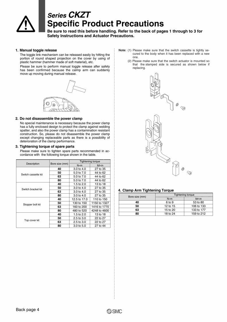
Series CKZTSpecific Product PrecautionsBe sure to read this before handling. Refer to the back of pages 1 through to 3 forSafety Instructions and Actuator Precautions.
Back page 4
1. Manual toggle releaseThe toggle link mechanism can be released easily by hitting the portion of round shaped projection on the cover by using of plastic hammer (hammer made of soft material), etc.Please be sure to perform manual toggle release after safety has been confirmed because the calmp arm can suddenly move up moving during manual release.
2. Do not disassemble the power clampNo special maintenance is necessary because the power clamp has a fully enclosed design to protect the clamp against welding spatter, and also the power clamp has a contamination resistant construction. So, please do not disassemble the power clamp except changing replaceable parts as there is a possibility of deterioration of the clamp performance.
3. Tightening torque of spare partsPlease make sure to tighten spare parts recommended in ac-cordance with the following torque shown in the table.
4. Clamp Arm Tightening Torque
40506380
6 to 912 to 1515 to 2018 to 24
53 to 80106 to 133133 to 177159 to 212
Bore size (mm)Tightening torque
N �m Ibf � in
40506380405063804050638040506380
3.0 to 4.05.0 to 7.05.0 to 7.05.0 to 7.01.5 to 2.03.0 to 4.03.0 to 4.03.0 to 4.0
12.5 to 17.0130 to 150160 to 200480 to 5201.5 to 2.02.5 to 3.02.5 to 3.03.0 to 5.0
27 to 3544 to 6244 to 6244 to 6213 to 1827 to 3527 to 3527 to 35
110 to 1501150 to 13271416 to 17704248 to 4600
13 to 1822 to 2722 to 2727 to 44
Bore size (mm)Tightening torque
Description
Switch cassette kit
Switch bracket kit
Stopper bolt kit
Top cover kit
N �m Ibf � in
Note: (1) Please make sure that the switch cassette is tightly se-cured to the body when it has been replaced with a new one.
(2) Please make sure that the switch actuator is mounted so that the stamped side is secured as shown below if replacing.
CKZT.qxd 05.11.11 9:44 AM Page 18

CKZT.qxd 05.11.11 9:44 AM Page 19

SMC'S GLOBAL MANUFACTURING, DISTRIBUTION AND SERVICE NETWORK
NORWAYSMC Pneumatics Norway A/S
POLANDSMC Industrial Automation Polska Sp.z.o.o.
ROMANIA SMC Romania s.r.l.
RUSSIA SMC Pneumatik LLC.
SLOVAKIASMC Priemyselná automatizáciá, s.r.o.
SLOVENIASMC INDUSTRIJSKA AVTOMATIKA d.o.o.
SPAIN/PORTUGALSMC España, S.A.
SWEDENSMC Pneumatics Sweden AB
SWITZERLANDSMC Pneumatik AG.
UKSMC Pneumatics (U.K.) Ltd.
ASIACHINASMC (China) Co., Ltd.
HONG KONGSMC Pneumatics (Hong Kong) Ltd.
INDIASMC Pneumatics (India) Pvt. Ltd.
INDONESIAPT. SMC Pneumatics Indonesia
MALAYSIASMC Pneumatics (S.E.A.) Sdn. Bhd.
PHILIPPINESSHOKETSU-SMC Corporation
SINGAPORESMC Pneumatics (S.E.A.) Pte. Ltd.
SOUTH KOREASMC Pneumatics Korea Co., Ltd.
TAIWANSMC Pneumatics (Taiwan) Co., Ltd.
THAILANDSMC Thailand Ltd.
NORTH AMERICACANADASMC Pneumatics (Canada) Ltd.
MEXICOSMC Corporation (Mexico) S.A. de C.V.USASMC Corporation of America
SOUTH AMERICAARGENTINASMC Argentina S.A.
BOLIVIASMC Pneumatics Bolivia S.R.L.
BRAZILSMC Pneumaticos Do Brazil Ltda.
CHILESMC Pneumatics (Chile) S.A.
VENEZUELASMC Neumatica Venezuela S.A.
OCEANIAAUSTRALIASMC Pneumatics (Australia) Pty. Ltd.
NEW ZEALANDSMC Pneumatics (N.Z.) Ltd.
EUROPEAUSTRIASMC Pneumatik GmbH
BELGIUMSMC Pneumatics N.V./S.A.
BULGARIASMC Industrial Automation Bulgaria EOOD
CROATIASMC Industrijska automatika d.o.o.
CZECH REPUBLICSMC Industrial Automation CZ s.r.o.
DENMARKSMC Pneumatik A/S
ESTONIASMC Pneumatics Estonia OÜ
FINLANDSMC Pneumatics Finland OY
FRANCESMC Pneumatique SA
GERMANYSMC Pneumatik GmbH
HUNGARYSMC Hungary Ipari Automatizálási Kft.
IRELANDSMC Pneumatics (Ireland) Ltd.
ITALYSMC Italia S.p.A.
LATVIASMC Pnuematics Latvia SIA
LITHUANIASMC Pneumatics Lithuania, UAB
NETHERLANDSSMC Pneumatics BV.
1-16-4 Shimbashi, Minato-ku, Tokyo 105-8659 JAPANTel: 03-3502-2740 Fax: 03-3508-2480URL http://www.smcworld.com© 2005 SMC Corporation All Rights Reserved
Specifications are subject to change without prior notice and any obligation on the part of the manufacturer.
1st printing JY printing JY 120DN Printed in Japan.D-DN
This catalog is printed on recycled paper with concern for the global environment.
CKZT.qxd 05.11.11 9:44 AM Page 20