Power and Cooling for Ultra-High Density Racks and Blade ... · © 2005 APC Corporation Power and...
74
® © 2005 APC Corporation Power and Cooling for Ultra-High Density Racks and Blade Servers White Paper #46
Transcript of Power and Cooling for Ultra-High Density Racks and Blade ... · © 2005 APC Corporation Power and...

®
© 2005 APC Corporation
Power and Cooling for Ultra-High
Density Racks and Blade Servers
White Paper #46

®
© 2005 APC Corporation
Introduction
♣ Average rack in a typical data center is under 2 kW
♣ Dense deployment of blade servers (10 -20 kW per rack) would greatly exceed the power and cooling ability of the typical data center
♣ Providing 10 -20kW of cooling per rack is technically infeasible using conventional methods
The ProblemThe Problem

®
© 2005 APC Corporation
Introduction
♣ There are practical strategies for installing, powering, and cooling high density racks either singly or in groups
♣ Some of these strategies challenge prevailing industry thinking on high -density deployment
The SolutionThe Solution

®
© 2005 APC Corporation
Introduction
♣ Wrong choices in designing for high density can increase Total Cost of Ownership for NCPI
by many timesby many times
The RiskThe RiskThe Risk
®
© 2005 APC Corporation
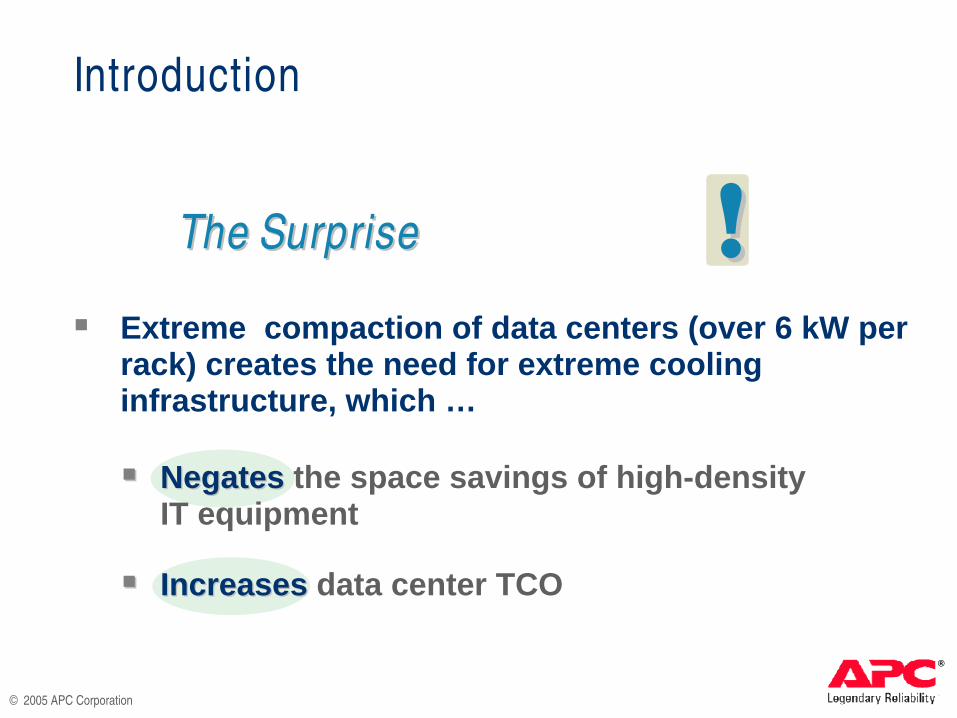
♣ Extreme compaction of data centers (over 6 kW per rack) creates the need for extreme cooling infrastructure, which …
♣♣ NegatesNegates the space savings of high -densityIT equipment
♣♣ IncreasesIncreases data center TCO
The SurpriseThe SurpriseThe Surprise !!
Introduction
®
© 2005 APC Corporation
High Density’s ChallengeHigh Density’s Challenge
to Conventional Coolingto Conventional Cooling

®
© 2005 APC Corporation
18 kW
POWER
18kW18 kW
COOLING
The Cooling Challenge
3 kW
3 kW
3 kW
3 kW
3 kW
3 kW

®
© 2005 APC Corporation
2500 cfm
18kW
3 kW
3 kW
3 kW
3 kW
3 kW
3 kW
2500 cfm
The Cooling Challenge

®
© 2005 APC Corporation
3 kW
3 kW
3 kW
3 kW
3 kW
3 kW
18kW
2500 cfm
Less than2500 cfmsupplied
Exhaust drawn from itself or fromneighboring racks
The Cooling Challenge

®
© 2005 APC Corporation
♣ Supply 2500 cfm of cool air to the rack
♣ Remove 2500 cfm of hot exhaust air from the rack
♣ Keep the hot exhaust air away from the equipment intake
♣ Provide all these functions in a redundant and uninterrupted manner
The Cooling Challenge:The Cooling Challenge:(For this 18kW rack)(For this 18kW rack)

®
© 2005 APC Corporation
3 kW
3 kW
3 kW
3 kW
3 kW
3 kW
Supp ly 2500 cfmSupp ly 2500 cfmof Cool Air to the Rackof Cool Air to the Rack
CHALLENGE # 1:
18kW

®
© 2005 APC Corporation
300cfm
300cfm
300cfm
300cfm
One 300 cfm vented tile per rack
Typical Raised-Floor Airflow
®
© 2005 APC Corporation
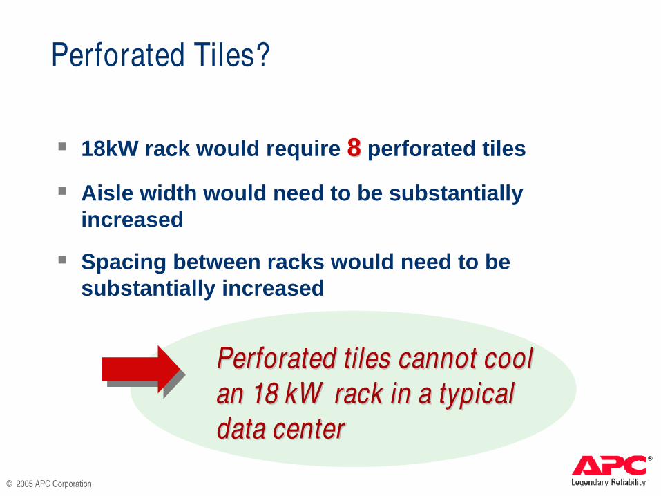
Perforated Tiles?
♣ 18kW rack would require 88 perforated tiles
♣ Aisle width would need to be substantially increased
♣ Spacing between racks would need to be substantially increased
Perforated tiles cannot cool Perforated tiles cannot cool
an 18 kW rack in a typical an 18 kW rack in a typical
data centerdata center

®
© 2005 APC Corporation Tile Airflow (cfm) [L/s]
Blade Servers
Standard IT Equipment
WithEffort
TypicalCapability
Extreme Impractical
12
10
8
6
4
2
00 100 200 300 400 500 600 700 800 900 1000
[47.2] [94.4] [141.6] [188.8] [236.0] [283.2] [330.4] [377.6] [424.8] [471.9]
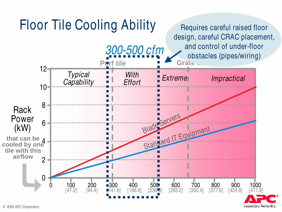
Floor Tile Cooling Ability
Perf tile Grate tile
RackPower(kW)
that can becooled by one tile with this
airflow
®
© 2005 APC Corporation
Grate tilePerf tile
Blade Servers
Standard IT Equipment
WithEffort
TypicalCapability
Extreme Impractical
12
10
8
6
4
2
00 100 200 300 400 500 600 700 800 900 1000
[47.2] [94.4] [141.6] [188.8] [236.0] [283.2] [330.4] [377.6] [424.8] [471.9]
Floor Tile Cooling Ability Requires careful raised floor
design, careful CRAC placement,
and control of under-floor
obstacles (pipes/wiring)300-500 cfm
RackPower(kW)
that can becooled by one tile with this
airflow

®
© 2005 APC Corporation
Grate tile
Blade Servers
Standard IT Equipment
WithEffort
TypicalCapability
Extreme Impractical
12
10
8
6
4
2
00 100 200 300 400 500 600 700 800 900 1000
[47.2] [94.4] [141.6] [188.8] [236.0] [283.2] [330.4] [377.6] [424.8] [471.9]
Floor Tile Cooling Ability
500-700 cfm
Additionally requires
grate-type tiles
Perf tile
RackPower(kW)
that can becooled by one tile with this
airflow
®
© 2005 APC Corporation
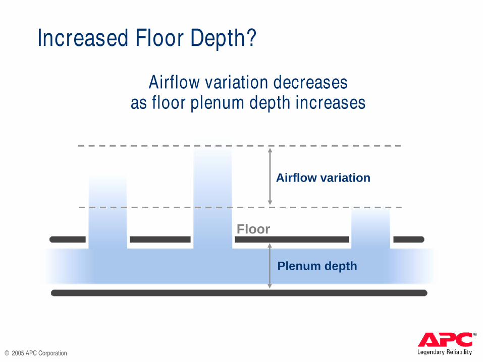
Increased Floor Depth?
Airflow variation
Plenum depth
Airflow variation decreasesas floor plenum depth increases
Floor

®
© 2005 APC Corporation
Increased Floor Depth?
Airflow variation
Plenum depth
Airflow variation
Plenum depth
Airflow variation decreasesas floor plenum depth increases
Floor

®
© 2005 APC Corporation
0%
50%
100%
150%
200%
250%
300%
350%
1 2 3 4 5 6
Floo r Plenum Depth ( feet) [meters]
Max
% T
ile A
irflo
w V
aria
tion
56% Open Tiles (grate)
25% Open Tiles (perforated)
[0.30] [0.61] [0.91] [1.22] [1.52]
Floor Plenum Depth
1 ft 2 ft 3 ft 4 ft 5 ft 6 ft 0.30 m 0.61 m 0.91 m 1.22 m 1.52 m 1.83 m
Max %Tile Airflow
Variation
350%
300%
250%
200%
150%
100%
50%
0%
Increased Floor Depth?
®
© 2005 APC Corporation
With grate-type tiles, airflow in some cases
reverses !Variation is large
even for very deep plenum

®
© 2005 APC Corporation
♣ Grate-type tiles dramatically alter under -floor pressure gradients, making cooling non -uniform and unpredictable
♣ Grate-type tiles in one area impact airflow in neighboring areas
♣ Large airflow variations when using grate -type tiles mean some locations will NOT receive enough cooling
♣ Even if an “extreme” cooling design couldsolve these large airflow variations, it would stilltake 33--44 grate -type tiles to cool one 18kW rack
Grate-Type Tiles?

®
© 2005 APC Corporation
A conventional data center layout with A conventional data center layout with
one vented tile per rack simply cannot one vented tile per rack simply cannot
cool racks over approximately 6 kW per cool racks over approximately 6 kW per
rack over a sustained arearack over a sustained area
Conventional Cooling Won’t Work

®
© 2005 APC Corporation
CHALLENGE # 2:
Remove 2500 cfm ofRemove 2500 cfm ofHot Air From the RackHot Air From the Rack
18kW
3 kW
3 kW
3 kW
3 kW
3 kW
3 kW

®
© 2005 APC Corporation
2500 cfm
18kW
Removing Heat
3 Ways to Remove Heat:3 Ways to Remove Heat:
♣ Through the room
♣ Through a duct
♣ Through ceiling plenum
3 kW
3 kW
3 kW
3 kW
3 kW
3 kW

®
© 2005 APC Corporation
Hot exhaust air from equipment is taken Hot exhaust air from equipment is taken
directly back to the cooling systemdirectly back to the cooling system
Removing Heat
2500 cfm through a 12 ”round duct goes 35 mph
1180 L/s through a 30 cm round duct goes 56 km/h
♣ Unobstructed, direct return path
♣ No chance to mix with surrounding air
♣ No chance to be drawn into equipment intakes
The ideal:The ideal:
®

®
© 2005 APC Corporation
These methods present high-density design challenges due to
high air velocity
Removing Heat
Typical methods used in data centersTypical methods used in data centers
♣ High, open ceiling with bulk air return at a central high point
♣ Return ductwork
♣ Suspended ceiling plenum
♣ Bulk air return across the room, under ceiling that is just a few feet above the racks

®
© 2005 APC Corporation
More thanMore than 400 cfm400 cfm (189 L/s) airflow per rack airflow per rack –– either either supply or return supply or return –– over a sustained area requires over a sustained area requires specialized engineering to ensure performance specialized engineering to ensure performance and redundancyand redundancy
Removing Heat

®
© 2005 APC Corporation
CHALLENGE # 3:
3 kW
3 kW
3 kW
3 kW
3 kW
3 kW
Keep Hot Exhaust Air Away Keep Hot Exhaust Air Away
From Equipment IntakeFrom Equipment Intake
®
18kW

®
© 2005 APC Corporation
Preventing Recirculation
♣ The shortest path for air to reach the equipment intake is recirculation from the equipment’s own exhaust
♣ In high density environments, high airflow velocities become subject to resistance in ductwork, which degrades airflow patterns
Supply and return paths must dominate Supply and return paths must dominate
airflow near potential recirculation paths to airflow near potential recirculation paths to
keep equipment from ingesting its own hot keep equipment from ingesting its own hot
exhaustexhaust

®
© 2005 APC Corporation
Cooling the data center

®
© 2005 APC Corporation
CHALLENGE # 4:
Provide Cooling in a Redundant and Provide Cooling in a Redundant and
Uninterrupted MannerUninterrupted Manner
®
Cooling must continue during downtime of a CRAC unit
Redundant
Cooling must continue during failover to generator backup
Uninterrupted

®
© 2005 APC Corporation
♣ Multiple CRAC units feed a shared raised floor or overhead plenum
♣ Plenum is assumed to sum all CRAC outputs and provide consistent pressure throughout
♣ System is designed to meet airflow and cooling requirements when any one CRAC unit is off
RedundantRedundant Cooling:Conventional Solution

®
© 2005 APC Corporation
Under fault conditions, cooling Under fault conditions, cooling
operation becomes unpredictableoperation becomes unpredictable
RedundantRedundant Cooling:High Density Challenge
♣ Airflow in cooling plenum increases
♣ Fundamental assumptions about shared -plenum system begin to break down
♣ With one CRAC unit off, local airflow velocities in the plenum are radically altered
♣ Airflow at an individual tile may even reversemay even reverse , drawing air down into floor from venturi effect

®
© 2005 APC Corporation
UninterruptedUninterrupted Cooling:Conventional Solution
♣ Conventional system puts CRACS on generator, not UPS
♣ Temperature rise during 5 -20 second generator startup is acceptable: 1° C (1.8° F)

®
© 2005 APC Corporation
UninterruptedUninterrupted Cooling:High Density Challenge
♣ In high density environment, temperature rise during uncooled 5-20 second generator startup can be 8 -30°C (14 -54°F)
♣ CRAC units may additionally have up to 5 -minute “settle” time after power outage before they can be restarted
With high power density, CRAC fans and pumps With high power density, CRAC fans and pumps
(CRAC(CRAC unitsunits, , in some cases) must be on the UPS to in some cases) must be on the UPS to
provide continuous cooling during generator startupprovide continuous cooling during generator startup
®
CRACs on UPS are a major cost driver and a major barrier to HD deployment

®
© 2005 APC Corporation
Five Strategies That WorkFive Strategies That Work

®
© 2005 APC Corporation
5 Strategies for DeployingHigh-Density Racks and Servers
1. Design room for peak rack density
Or design room Or design room BELOWBELOW peak rack density, andpeak rack density, and ……
2. Provide supplemental cooling for high -density racks
3. Establish rules for interspersed high -densityracks to borrow cooling from adjacent racks
5. Create a separate highly cooled area for high -density equipment
4. Spread out high -density equipment among multiple racks

®
© 2005 APC Corporation
Strategy #1Strategy #1Design Room For Peak Rack Density
♣ Handles wide range of futurehigh -density scenarios
♣ Requires very complexanalysis and engineering
♣ Capital and operating cost upto 4x alternative methods
♣ Risk of extreme underutilization of expensive infrastructure
♣ For rare and extreme cases of large farms of high -density equipment and limited space

®
© 2005 APC Corporation
Strategy #2Strategy #2Supplemental Cooling for HD Racks
♣ Specialty floor tiles or fans to boost cool air supply to rack
♣ Specialty return ducts or fansto scavenge hot exhaust fromracks for return to the CRAC
♣ Special racks or rack -mountedcooling devices to provide cooling directly to the rack
Types of supplemental cooling:Types of supplemental cooling:

®
© 2005 APC Corporation
♣ Provides high density whenand where needed
♣ Defers capital cost of upgradingto high -density infrastructure
♣ High efficiency
♣ Optimal use of floor space
♣ Limited to about 10 kW per rack
♣ Room must be designed in advance to allow it
Strategy #2Supplemental-Cooling:Considerations

®
© 2005 APC Corporation
♣ New construction or renovation
♣ Mixed environment
♣ When location of high -densityequipment is not known inadvance
Supplemental-Cooling:Applications Strategy #2
®
© 2005 APC Corporation
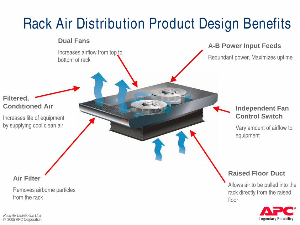
Rack Air Distribution Product Design Benefits
Filtered, Conditioned Air
Increases life of equipment
by supplying cool clean air
Raised Floor Duct
Allows air to be pulled into the
rack directly from the raised
floor
Dual Fans
Increases airflow from top to
bottom of rack
Air Filter
Removes airborne particles
from the rack
Rack Air Distribution Unit
A-B Power Input Feeds
Redundant power, Maximizes uptime
Independent Fan Control Switch
Vary amount of airflow to
equipment

®
© 2005 APC CorporationRack Air Distribution Unit
Rack Air Distribution Unit Airflow Diagram
♣ Conditioned Room Air Is:♣ Pulled in from underneath
raised floor♣ Delivered from bottom to
top of rack by dual fans ♣ Drawn in by the IT
equipment
♣ Provides Cooler Air to the Rack♣ Provides better cooling for
IT equipment reducing heat related failures
♣ Extends the life of equipment in the rack

®
© 2005 APC Corporation
ARU AIR FLOW
®
© 2005 APC CorporationRack Air Removal Unit
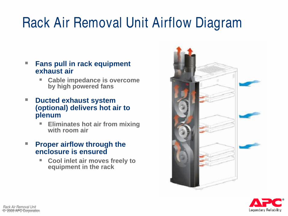
Rack Air Removal Unit Airflow Diagram
♣ Fans pull in rack equipment exhaust air♣ Cable impedance is overcome
by high powered fans
♣ Ducted exhaust system (optional) delivers hot air to plenum♣ Eliminates hot air from mixing
with room air
♣ Proper airflow through the enclosure is ensured♣ Cool inlet air moves freely to
equipment in the rack

®
© 2005 APC Corporation
ADU Air Flow

®
© 2005 APC Corporation
ARU with Fully Ducted Return

®
© 2005 APC Corporation
♣ Common and effective strategyin typical data centers
♣ Unused cooling capacity fromneighboring racks can be usedfor up to 3x design density
♣ Uses rules for locatinghigh -density racks to avoidcreating hot spots
♣ Compliance can be verified by monitoring power consumption at the rack level
Strategy #3Strategy #3Borrow Cooling From Adjacent Racks

®
© 2005 APC Corporation
♣ No new equipment needed
♣ Essentially “free” in many cases
♣ High -density racks are limitedto about 2x average density
♣ Requires more floor space than supplemental -coolingstrategy (lower density)
♣ Requires enforcement of deployment rules
“ Borrowed Cooling”Considerations Strategy #3

®
© 2005 APC Corporation
“ Borrowed Cooling”Applications Strategy #3
♣ For existing data centers, whenhigh -density equipment isa small fraction of total load

®
© 2005 APC Corporation
START: New proposed load
®
Add up rack’s existing power plus new load
Does new rackpower exceed avg.
cooling power?
Does eitheradjacent rack exceed avg. cooling power?
Is rack at the end of a row?
Does avg. ofnew and adjacent rack
exceed avg. cooling power?
Does avg. ofnew and 2 adjacent racks
exceed avg. cooling power?
New loadmay be deployed
New loadmay not be deployed
Split up load or try different location
Strategy #3
YES
YES
NO YES
NO
NO
YESYESNO NO
“ Borrowed Cooling”Example of Deployment Rules

®
© 2005 APC Corporation
“ If the proposed rack averaged with its
neighbors (only one neighbor if at the end of a
row) does not exceed design average power,
AND neither neighbor is already a high -density
rack, then it ’s OK to put it there ”
Strategy #3“ Borrowed Cooling”
Example of Deployment Rules

®
© 2005 APC Corporation
♣ Most popular solution
♣ High -density equipment is spread out among many racks
♣ No rack exceeds design powerdensity
♣ Predictable cooling performance
Strategy #4Strategy #4Split Up High Density Equipment

®
© 2005 APC Corporation
Splitting Up Equipment:Considerations Strategy #4
♣ No new equipment needed
♣ Essentially “free” in many cases
♣ High -density equipment must bespread out even more than in“borrowing” strategy
♣ Uses more floor space than fullhigh -density racks
♣ Can cause data cabling problems
♣ Empty vertical space must be filledwith blanking panels blanking panels to prevent in -rack recirculation of hot exhaust air
®
© 2005 APC Corporation
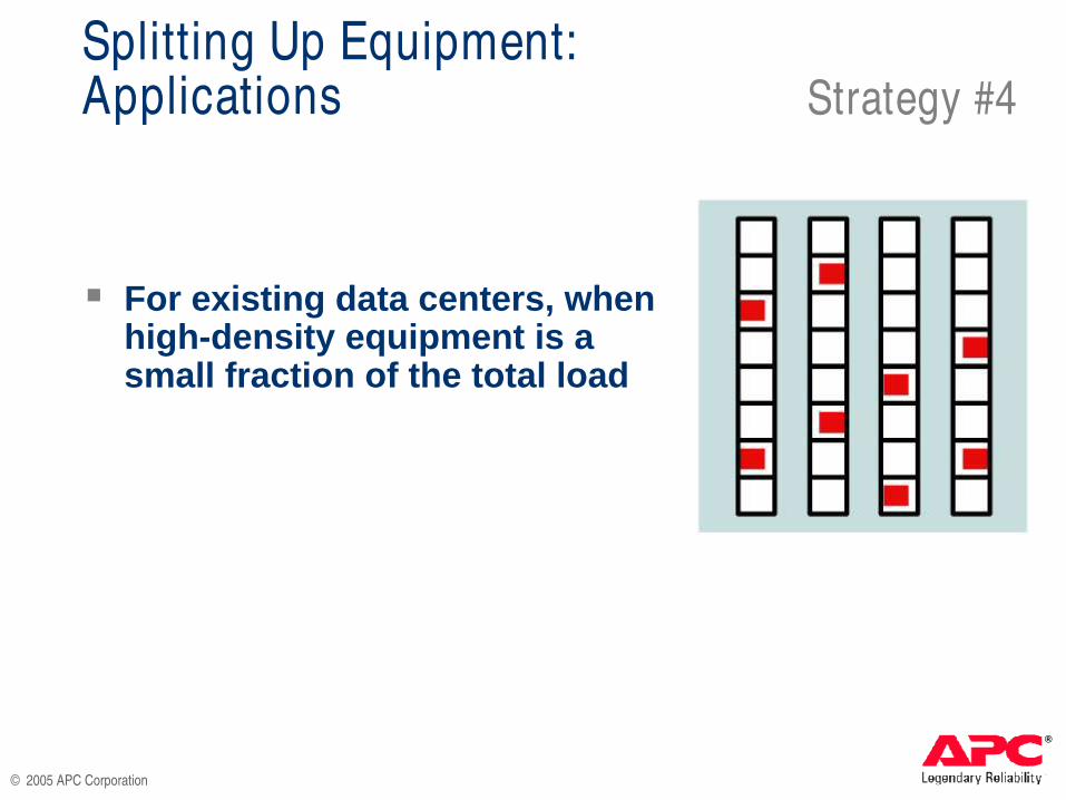
Splitting Up Equipment:Applications Strategy #4
♣ For existing data centers, when high -density equipment is asmall fraction of the total load

®
© 2005 APC Corporation
SIDE VIEW SIDE VIEW
Strategy #4Blanking Panels
BEFORE AFTER
Rack front
79ºF 32ºC
73ºF 32ºC
73ºF 32ºC
72ºF 32ºC
73ºF 32ºC
70ºF 32ºC
Rack front
90ºF 32ºC
80ºF 27ºC
95ºF 35ºC
83ºF 28ºC
72ºF 22ºC
70ºF 21ºC
Server Inlet Temp
Blankingpanels

®
© 2005 APC Corporation
Air Flow with no
blanking panels

®
© 2005 APC Corporation
Blanking panels block internal recirculationBlanking panels block internal recirculation
SIDE VIEW SIDE VIEW
Strategy #4Blanking Panels
BEFORE AFTER
Rack front
Rack front
90ºF 32ºC
80ºF 27ºC
95ºF 35ºC
83ºF 28ºC
72ºF 22ºC
70ºF 21ºC
79ºF 32ºC
73ºF 32ºC
73ºF 32ºC
72ºF 32ºC
73ºF 32ºC
70ºF 32ºC
Blankingpanels

®
© 2005 APC Corporation
Air Flow with blanking panels
®
© 2005 APC Corporation
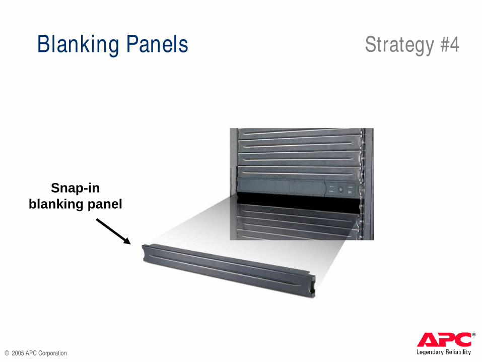
Strategy #4Blanking Panels
Snap-in blanking panel
®
© 2005 APC Corporation
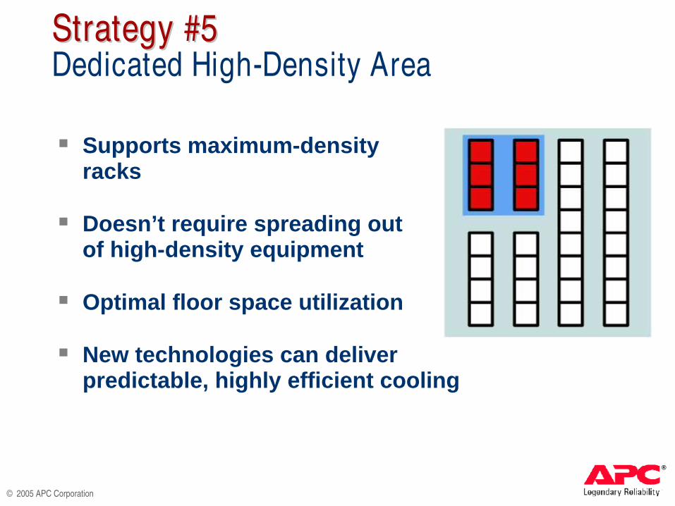
♣ Supports maximum -densityracks
♣ Doesn’t require spreading outof high -density equipment
♣ Optimal floor space utilization
♣ New technologies can deliverpredictable, highly efficient cooling
Strategy #5Strategy #5Dedicated High-Density Area

®
© 2005 APC Corporation
Dedicated High-Density Area:Considerations
♣ Requires prior knowledge ofnumber of high -density racks
♣ Need to plan high -density areain advance and reserve spacefor it
♣ Requires ability to segregatehigh -density equipment
Strategy #5

®
© 2005 APC Corporation
Dedicated High-Density Area:Applications Strategy #5
♣ New construction or renovations
♣ Density of 10 -25 kW per rack
♣ High -density co -location

®
© 2005 APC Corporation
Strategy #5Dedicated High-Density Area:Power / Cooling Technology
Equipment racks take inambient air from front
Ambient-temperature air is returned to room
Hot aisle
All exhaust air iscaptured within chamber and
“ neutralized” to ambient temperature
Integral rackair conditioner
Integral rack power distribution system
(UPS is optional)
Can operate on hard floor or raised floor
Door access to hot aisle and rear of IT equipment

®
© 2005 APC Corporation
ISX High Density Air Flow Pattern

®
© 2005 APC Corporation
Summary and RecommendationsSummary and Recommendations
Seven Elements of anSeven Elements of an
Optimal Cooling StrategyOptimal Cooling Strategy
®
© 2005 APC Corporation
Elements of Optimal Cooling Strategy
Ignore physical size of equipment and
focus on functionality per watt consumed
11
Minimizes area and TCO

®
© 2005 APC Corporation
Design the system to permit later installation
of supplemental cooling devices
22Elements of Optimal Cooling Strategy
Allows for future supplemental cooling equipment
where and when needed, on a live data center, in
the face of uncertain future requirements

®
© 2005 APC Corporation
Choose a room average power density between 40 and 100 W / ft2
33
Practical for most new designs:80 W / ft2 or 2.8 kW / rack
.9 kW / m2
0.4 – 1.1 kW / m2
Elements of Optimal Cooling Strategy
♣ Avoids waste due to oversizing
♣ Keeps both routine and redundant performance predictable

®
© 2005 APC Corporation
If the fraction of high density loads is high
and predictable, establish high-density areas
of 100-400 w / ft2 (3-13 kW per rack)
44
1.1 – 4.3 kW / m 2
Elements of Optimal Cooling Strategy
♣ Requires planning ahead for specially equipped areas
♣ Adds significant cost, time, and complexity
♣ These areas do not use raised-floor cooling

®
© 2005 APC Corporation
Establish policies/rules for allowable rack
power based on location and adjacent loads
55Elements of Optimal Cooling Strategy
♣ Reduces hot spots
♣ Ensures cooling redundancy
♣ Increases system cooling efficiency
♣ Reduces electrical consumption
♣ More sophisticated rules and monitoring can enable even higher power density

®
© 2005 APC Corporation
Use supplemental cooling devices where
indicated
66Elements of Optimal Cooling Strategy
Boosts local cooling capacity up to 3x room design
to accommodate high-density equipment

®
© 2005 APC Corporation
Split up equipment that cannot be installed
to meet the rules
77Elements of Optimal Cooling Strategy
♣ Lowest cost, lowest risk option
♣ Consumes considerable space if there is more than a small fraction of high-density loads
♣ Chosen as primary strategy by users without significant area constraints

®
© 2005 APC Corporation
Questions?

®
© 2005 APC Corporation