Pot Bearings - Canam-Bridges – Building Better Bridges€¦ · GZT SLIDE The GZT slide is a ......
20
POT BEARINGS
-
Upload
nguyendiep -
Category
Documents
-
view
217 -
download
2
Transcript of Pot Bearings - Canam-Bridges – Building Better Bridges€¦ · GZT SLIDE The GZT slide is a ......

POT BEARINGS

THE PURSUIT OF A BETTER CUSTOMER EXPERIENCE
OUR MISSION
TABLE OF CONTENTS
Features .......................................................................................... 3
Design Principle .............................................................................. 4
Applications .................................................................................... 5
Materials ......................................................................................... 6
Design ............................................................................................ 7
Service Offer .................................................................................. 8
Pot Bearing Selection Charts
• PF Series Fixed Bearings .........................................................10
• PM Series Multidirectional Bearings ........................................11
• PMG Series Unidirectional Edge-Guided Bearings ..................12
• PMCG Series Unidirectional Center-Guided Bearings ..............13
Bearings with Uplift Restraint Device ............................................14
Connection Details .........................................................................15
Installation, Handling and Storage ..................................................16
Quality Commitment .....................................................................19
2

COMPLETE RANGE OF STRUCTURAL BEARINGS FOR BRIDGES AND OTHER CIVIL ENGINEERING PROJECTS
All structures are flexible and their structural integrity must be maintained under all conditions. A structural bearing is essential to providing free movement between the superstructure and the supporting structure, while ensuring the safe transfer of vertical loads and rotations.
POT BEARINGS (CONFINED ELASTOMER)
Goodco Z-Tech pot bearings consist of an assembly of precision-machined steel components and an elastometric disc confined at the centre. Designed and sized according to your project specific requirements, these bearings transfer large vertical loads while accommodating the structure’s relative displacement. Whether they are fixed, unidirectional or multidirectional, pot bearings transfer vertical and horizontal load combinations as well as longitudinal and transverse displacements. They can also be equipped with an uplift restraint device.
POT BEARINGS
FEATURES
• Very low sliding friction
• Low eccentricity under vertical load and rotation
• Unlimited displacement capability
• Unlimited rotation capacity around vertical axis
• Horizontal rotation not reduced by guide system
• Replaceable
• Self-alignment capability
• Easy installation
• Low maintenance
PF Series fixed pot bearing assembly with uplift restraint device
3

The design principle of the Goodco Z-Tech P Series or pot bearing is that of a fixed bearing, which restrains horizontal displacement, but allows rotational movement of the bridge structure about any horizontal axis by shear deformation of an elastomeric disc confined in a steel casing (pot plate).
The pot is machined from a standard steel plate to the proper dimensions. Brass sealing rings prevent the elastomeric disc encased in the pot from extruding under pressure through the annular gap located between the piston and the inside of the pot plate. The piston, which fits in the pot, is in contact with the elastomeric disc (Figure 1).
When sliding components are added, the above fixed bearing becomes a mobile bearing that can accommodate horizontal displacement. This horizontal displacement can be multidirectional or unidirectional if a guiding system is provided. These sliding components consist of a polished stainless steel sheet welded to the underside of a steel plate and a PTFE disc bonded to the upper surface of the pot or piston plate. In order to increase its load-bearing capacity, the PTFE disc is recessed into the steel to a depth equal to approximately one-half of its thickness. The PTFE disc has small cavities (lubrication dimples) that contain a special lubricant to ensure permanent lubrication of the sliding surfaces.
DESIGN PRINCIPLE
Figure 1 Cross-section of the central core of a pot bearing
Under vertical loads, the confined elastomeric disc behaves like a viscous fluid exhibiting the following characteristics:
• No vertical deflection under load (incompressible elastomer).
• Evenly distributed pressure over the entire surface.
• Constant volume under vertical load and rotation.
• Minimum eccentricity of vertical load under rotation.
PMCG Series unidirectional center-guided bearing
Piston plate
Pot plateSealant
Sealing rings
Elastomeric disc
4

Goodco Z-Tech manufactured 80 pot bearings – PF Series fixed, PM Series multidirectional and PMCG Series unidirectional – for the five-lane Athabasca River Bridge.
Goodco Z-Tech pot bearings can be used for bridges, railway and highway overpasses and buildings.
APPLICATIONS
Athabasca River Bridge – Fort McMurray, AB With a deck surface of 15,500 m2 (166,841 sq. ft.), this is Alberta’s widest bridge.
5

MATERIALS
STEEL COMPONENTS
All steel plates conform to CSA G40.20/G40.21, Grade 260W (ASTM A36), 300W, 350W (ASTM A572, Grade 50) or 350A (ASTM A588). Other steel grades can also be supplied, depending on their availability or the project’s specific requirements.
STAINLESS STEEL
The stainless steel conforms to ASTM A240/A240M, Type 304 or approved equivalent. The roughness of the surface in contact with the PTFE, measured in accordance with CSA B95, does not exceed an arithmetic mean of 0.25 μm.
PTFE (POLYETRAFLUOROETHYLENE/TEFLON®)
The PTFE discs and strips are manufactured from pure unfilled sheets and are chemically etched on one face to improve bonding.
GZT SLIDE
The GZT slide is a metal-polymer composite that has very good wear and low friction. It is exclusively used on the guide bars and it meets the requirements of EN 1337-2.
ELASTOMER
The elastomer material for the elastomeric pad has a hardness of 50 ± 5 DURO and conforms to CAN/CSA, Table 11.5, or ASSHTO M251, Table 1.
LUBRICANT
The lubricant for the elastomer conforms to MIL-G-4343-C. The lubricant for the PTFE disc conforms to MIL-S-8660C.
SEALING RINGS
The sealing rings are manufactured from half-hard, cold-rolled, 260 alloy brass in conformity with ASTM B36 / B36M.
ANCHORING SYSTEM
The fusion-welded studs conform to ASTM A108, Grade 1015, 1018 or 1020. The steel rods conform to CSA G40.20/G40.21, Grade 260W (ASTM A36), 300W, 350W or ASTM F1554, Grade 105 (ASTM A193 B7). The connecting bolts conform to ASTM A325, A490 or F3125.
STEEL FINISH
The exposed steel surfaces are zinc-metallized to a minimum thickness of 175 microns in conformity with CSA G189 (AWS C2.23M/C2.23). For severe environmental conditions, or to increase the life expectancy of the zinc metallized surface, the thickness of the zinc layer can be increased to 250 microns. The connection bolts and certain plates are hot-dipped galvanized in conformity with ASTM A123/A123M.
PMG Series unidirectional edge-guided bearing
The PTFE disc is cleaned before the silicon lubricant is applied.
6
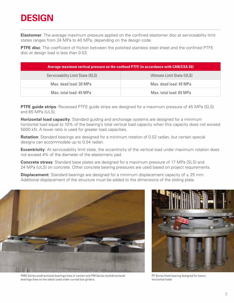
PF Series fixed bearing designed for heavy horizontal loads
PMG Series unidirectional bearings (two in center) and PM Series multidirectional bearings (two on the sides) used under curved box girders.
Elastomer: The average maximum pressure applied on the confined elastomer disc at serviceability limit states ranges from 24 MPa to 40 MPa, depending on the design code.
PTFE disc: The coefficient of friction between the polished stainless steel sheet and the confined PTFE disc at design load is less than 0.03.
PTFE guide strips: Recessed PTFE guide strips are designed for a maximum pressure of 45 MPa (SLS) and 65 MPa (ULS).
Horizontal load capacity: Standard guiding and anchorage systems are designed for a minimum horizontal load equal to 10% of the bearing’s total vertical load capacity when this capacity does not exceed 5000 kN. A lower ratio is used for greater load capacities.
Rotation: Standard bearings are designed for a minimum rotation of 0.02 radian, but certain special designs can accommodate up to 0.04 radian.
Eccentricity: At serviceability limit state, the eccentricity of the vertical load under maximum rotation does not exceed 4% of the diameter of the elastomeric pad.
Concrete stress: Standard base plates are designed for a maximum pressure of 17 MPa (SLS) and 24 MPa (ULS) on concrete. Other concrete bearing pressures are used based on project requirements.
Displacement: Standard bearings are designed for a minimum displacement capacity of ± 25 mm. Additional displacement of the structure must be added to the dimensions of the sliding plate.
DESIGN
Average maximum vertical pressure on the confined PTFE (in accordance with CAN/CSA S6)
Serviceability Limit State (SLS) Ultimate Limit State (ULS)
Max. dead load: 30 MPa Max. dead load: 45 MPa
Max. total load: 45 MPa Max. total load: 65 MPa
7
SERVICE OFFER
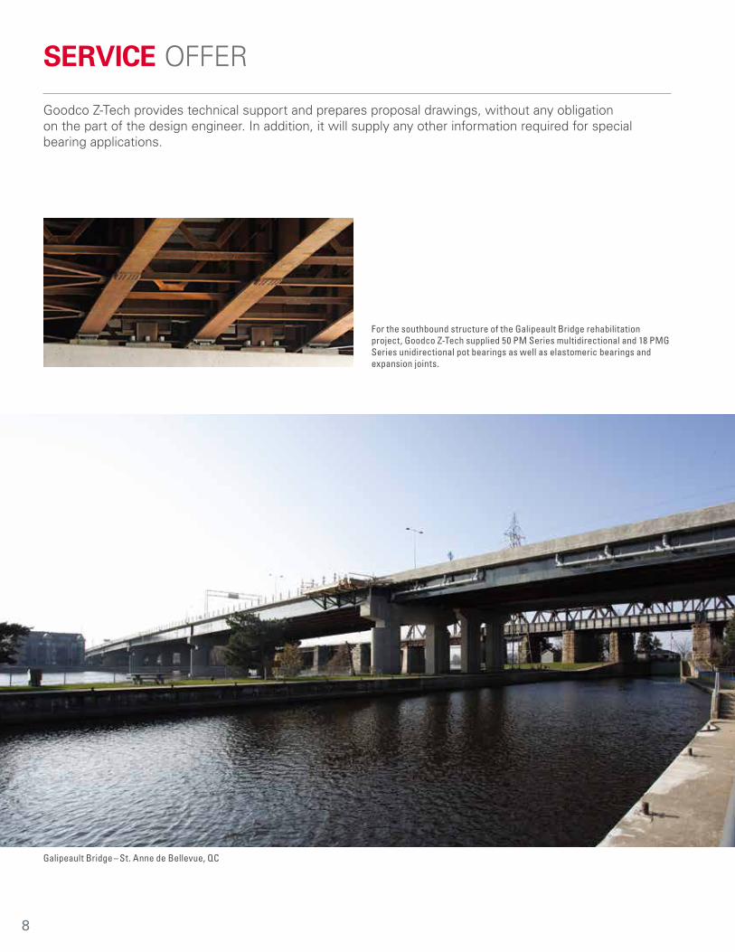
Goodco Z-Tech provides technical support and prepares proposal drawings, without any obligation on the part of the design engineer. In addition, it will supply any other information required for special bearing applications.
Galipeault Bridge – St. Anne de Bellevue, QC
For the southbound structure of the Galipeault Bridge rehabilitation project, Goodco Z-Tech supplied 50 PM Series multidirectional and 18 PMG Series unidirectional pot bearings as well as elastomeric bearings and expansion joints.
8

Photo : Kiewit-Parsons
Highway 25 Bridge – Montreal/Laval, QC
PM Series multidirectional bearing installed at pylon No. 11 of the Highway 25 Bridge.
Goodco Z-Tech manufactured pot bearings and lateral restraint systems for the cable-stayed span of the new Highway 25 Bridge over the Rivière des Prairies.
--
9
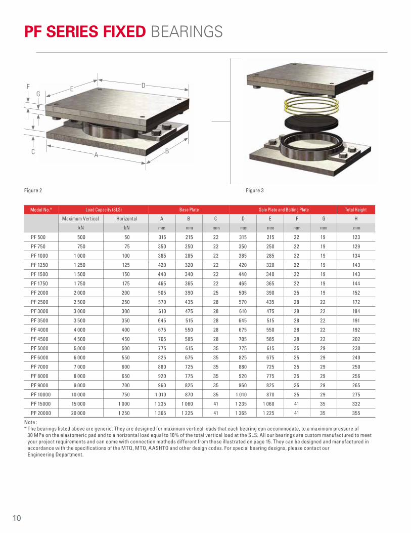
Note : * The bearings listed above are generic. They are designed for maximum vertical loads that each bearing can accommodate, to a maximum pressure of
30 MPa on the elastomeric pad and to a horizontal load equal to 10% of the total vertical load at the SLS. All our bearings are custom manufactured to meet your project requirements and can come with connection methods different from those illustrated on page 15. They can be designed and manufactured in accordance with the specifications of the MTQ, MTO, AASHTO and other design codes. For special bearing designs, please contact our Engineering Department.
Load Capacity (SLS) Base Plate Sole Plate and Bolting Plate Total HeightModel No.*
Maximum Vertical Horizontal A B C D E F G H
kN kN mm mm mm mm mm mm mm mm
PF 500 500 50 315 215 22 315 215 22 19 123
PF 750 750 75 350 250 22 350 250 22 19 129
PF 1000 1 000 100 385 285 22 385 285 22 19 134
PF 1250 1 250 125 420 320 22 420 320 22 19 143
PF 1500 1 500 150 440 340 22 440 340 22 19 143
PF 1750 1 750 175 465 365 22 465 365 22 19 144
PF 2000 2 000 200 505 390 25 505 390 25 19 152
PF 2500 2 500 250 570 435 28 570 435 28 22 172
PF 3000 3 000 300 610 475 28 610 475 28 22 184
PF 3500 3 500 350 645 515 28 645 515 28 22 191
PF 4000 4 000 400 675 550 28 675 550 28 22 192
PF 4500 4 500 450 705 585 28 705 585 28 22 202
PF 5000 5 000 500 775 615 35 775 615 35 29 230
PF 6000 6 000 550 825 675 35 825 675 35 29 240
PF 7000 7 000 600 880 725 35 880 725 35 29 250
PF 8000 8 000 650 920 775 35 920 775 35 29 256
PF 9000 9 000 700 960 825 35 960 825 35 29 265
PF 10000 10 000 750 1 010 870 35 1 010 870 35 29 275
PF 15000 15 000 1 000 1 235 1 060 41 1 235 1 060 41 35 322
PF 20000 20 000 1 250 1 365 1 225 41 1 365 1 225 41 35 355
FG
E
B
D
AC
PF SERIES FIXED BEARINGS
Figure 2 Figure 3
--
10

Notes : * The bearings listed above are generic. They are designed for maximum vertical loads that each bearing can accommodate, to a maximum pressure of
30 MPa on the elastomeric pad at the SLS. All our bearings are custom designed to meet your project requirements and can come with connection methods different from those illustrated on page 15. They can be designed and manufactured in accordance with the specifications of the MTQ, MTO, AASHTO and other design codes. For special bearing designs, please contact our Engineering Department.
** Standard bearings are designed for a total movement of 50 mm (± 25 mm). Any additional movement required must be added to dimensions “D” or “E”.
Load Capacity (SLS) Base Plate Sole Plate and Sliding Plate Total HeightModel No.*
Maximum Vertical A B C D** E** F G H
kN mm mm mm mm mm mm mm mm
PM 500 500 315 215 22 315 225 22 19 127
PM 750 750 345 245 22 345 255 22 19 131
PM 1000 1 000 375 275 22 375 275 22 19 133
PM 1250 1 250 400 310 22 400 310 22 19 136
PM 1500 1 500 420 340 22 420 340 22 19 136
PM 1750 1 750 450 365 22 450 365 22 19 138
PM 2000 2 000 485 390 25 485 390 25 19 146
PM 2500 2 500 545 435 28 545 435 28 22 163
PM 3000 3 000 580 475 28 580 475 28 25 172
PM 3500 3 500 610 515 28 610 515 31 28 183
PM 4000 4 000 645 550 28 645 550 31 31 187
PM 4500 4 500 670 585 28 670 585 35 31 194
PM 5000 5 000 740 615 35 740 615 35 35 212
PM 6000 6 000 785 675 35 785 675 38 38 225
PM 7000 7 000 835 725 35 835 725 41 41 241
PM 8000 8 000 875 775 35 875 775 44 41 254
PM 9000 9 000 915 825 35 915 825 47 47 268
PM 10000 10 000 965 870 34 965 870 50 47 275
PM 15000 15 000 1 185 1 060 41 1 185 1 060 60 57 329
PM 20000 20 000 1 305 1 225 47 1 305 1 225 69 66 376
F
GE
B
D
AC
PM SERIES MULTIDIRECTIONAL BEARINGS
Figure 4 Figure 5
--
11
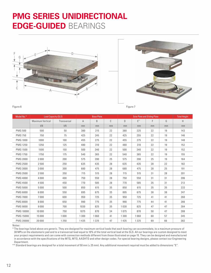
Notes : * The bearings listed above are generic. They are designed for maximum vertical loads that each bearing can accommodate, to a maximum pressure of
30 MPa on the elastomeric pad and to a transversal load equal to 10% of the total vertical load at the SLS. All our bearings are custom designed to meet your project requirements and can come with connection methods different from those illustrated on page 15. They can be designed and manufactured in accordance with the specifications of the MTQ, MTO, AASHTO and other design codes. For special bearing designs, please contact our Engineering Department.
** Standard bearings are designed for a total movement of 50 mm (± 25 mm). Any additional movement required must be added to dimensions “E”.
Load Capacity (SLS) Base Plate Sole Plate and Sliding Plate Total HeightModel No.*
Maximum Vertical Transversal A B C D E** F G H
kN kN mm mm mm mm mm mm mm mm
PMG 500 500 50 380 215 22 380 225 22 19 143
PMG 750 750 75 425 245 22 425 255 22 19 146
PMG 1000 1000 100 455 275 22 455 275 22 19 148
PMG 1250 1250 125 480 310 22 480 310 22 19 152
PMG 1500 1500 150 500 340 22 500 340 22 19 152
PMG 1750 1750 175 540 365 22 540 365 22 19 155
PMG 2000 2 000 200 575 390 25 575 390 25 19 164
PMG 2500 2 500 250 635 435 28 635 435 28 22 182
PMG 3000 3 000 300 680 475 28 680 475 28 25 191
PMG 3500 3 500 350 715 515 28 715 515 31 28 201
PMG 4000 4 000 400 750 550 28 750 550 31 31 206
PMG 4500 4 500 450 770 585 28 770 585 35 31 213
PMG 5000 5 000 500 850 615 35 850 615 35 35 233
PMG 6000 6 000 550 895 675 35 895 675 38 38 247
PMG 7000 7 000 600 950 725 35 950 725 41 41 260
PMG 8000 8 000 650 990 775 35 990 775 44 41 266
PMG 9000 9 000 700 1030 825 35 1 030 825 47 47 284
PMG 10000 10 000 750 1075 870 34 1 075 870 50 47 288
PMG 15000 15 000 1 000 1 300 1 060 41 1 300 1 060 60 57 345
PMG 20000 20 000 1 250 1 435 1 225 47 1 435 1 225 69 66 382
FG
E
B
D
AC
PMG SERIES UNIDIRECTIONAL EDGE-GUIDED BEARINGS
Figure 6 Figure 7
--
12
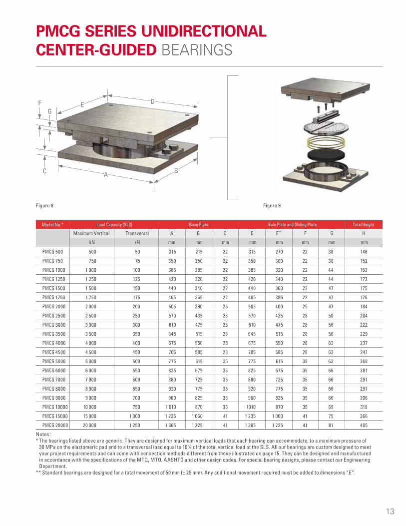
Notes : * The bearings listed above are generic. They are designed for maximum vertical loads that each bearing can accommodate, to a maximum pressure of
30 MPa on the elastomeric pad and to a transversal load equal to 10% of the total vertical load at the SLS. All our bearings are custom designed to meet your project requirements and can come with connection methods different from those illustrated on page 15. They can be designed and manufactured in accordance with the specifications of the MTQ, MTO, AASHTO and other design codes. For special bearing designs, please contact our Engineering Department.
** Standard bearings are designed for a total movement of 50 mm (± 25 mm). Any additional movement required must be added to dimensions “E”.
Load Capacity (SLS) Base Plate Sole Plate and Sliding Plate Total HeightModel No.*
Maximum Vertical Transversal A B C D E** F G H
kN kN mm mm mm mm mm mm mm mm
PMCG 500 500 50 315 215 22 315 270 22 38 146
PMCG 750 750 75 350 250 22 350 300 22 38 152
PMCG 1000 1 000 100 385 285 22 385 320 22 44 163
PMCG 1250 1 250 125 420 320 22 420 340 22 44 172
PMCG 1500 1 500 150 440 340 22 440 360 22 47 175
PMCG 1750 1 750 175 465 365 22 465 385 22 47 176
PMCG 2000 2 000 200 505 390 25 505 400 25 47 184
PMCG 2500 2 500 250 570 435 28 570 435 28 50 204
PMCG 3000 3 000 300 610 475 28 610 475 28 56 222
PMCG 3500 3 500 350 645 515 28 645 515 28 56 229
PMCG 4000 4 000 400 675 550 28 675 550 28 63 237
PMCG 4500 4 500 450 705 585 28 705 585 28 63 247
PMCG 5000 5 000 500 775 615 35 775 615 35 63 268
PMCG 6000 6 000 550 825 675 35 825 675 35 66 281
PMCG 7000 7 000 600 880 725 35 880 725 35 66 291
PMCG 8000 8 000 650 920 775 35 920 775 35 66 297
PMCG 9000 9 000 700 960 825 35 960 825 35 66 306
PMCG 10000 10 000 750 1 010 870 35 1010 870 35 69 319
PMCG 15000 15 000 1 000 1 235 1 060 41 1 235 1 060 41 75 366
PMCG 20000 20 000 1 250 1 365 1 225 41 1 365 1 225 41 81 405
FG
E
B
D
AC
PMCG SERIES UNIDIRECTIONAL CENTER-GUIDED BEARINGS
Figure 8 Figure 9
--
13
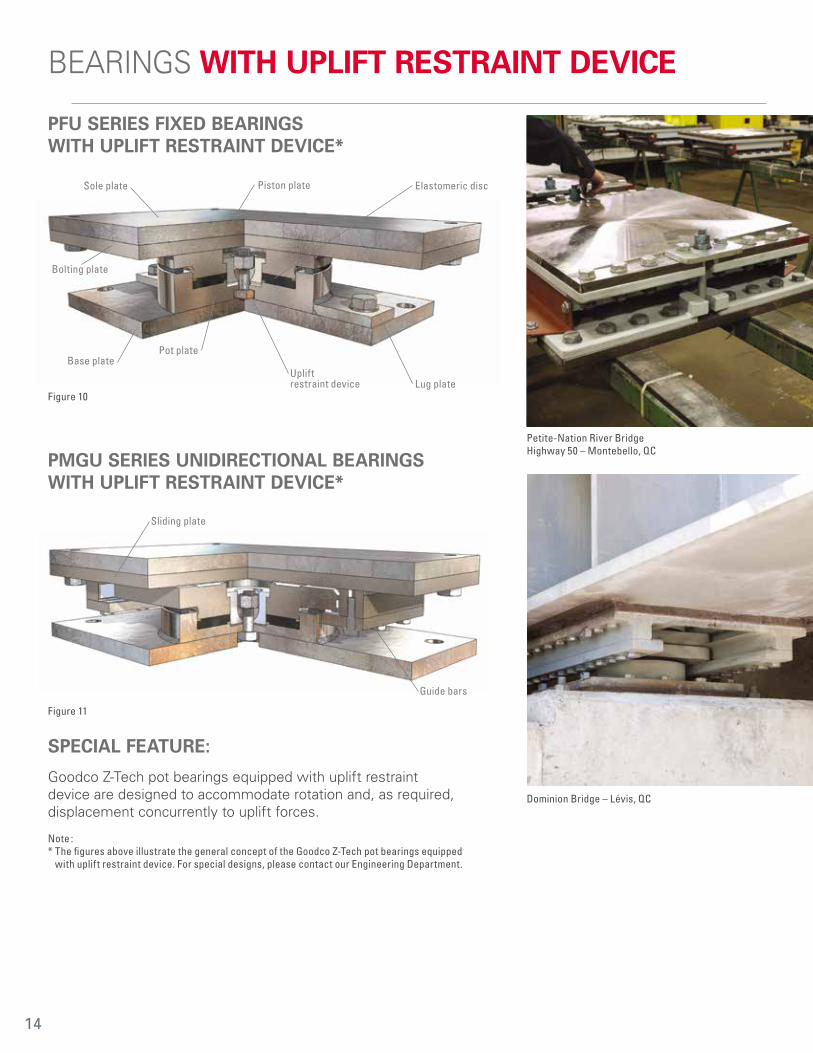
--PFU SERIES FIXED BEARINGS WITH UPLIFT RESTRAINT DEVICE*
PMGU SERIES UNIDIRECTIONAL BEARINGS WITH UPLIFT RESTRAINT DEVICE*
SPECIAL FEATURE:
Goodco Z-Tech pot bearings equipped with uplift restraint device are designed to accommodate rotation and, as required, displacement concurrently to uplift forces.
Note :* The figures above illustrate the general concept of the Goodco Z-Tech pot bearings equipped
with uplift restraint device. For special designs, please contact our Engineering Department.
Lug plate
Elastomeric discPiston plate
Uplift restraint device
Sole plate
Base platePot plate
Bolting plate
Sliding plate
Guide bars
BEARINGS WITH UPLIFT RESTRAINT DEVICE
Figure 10
Dominion Bridge – Lévis, QC
Figure 11
Petite-Nation River Bridge Highway 50 – Montebello, QC
14

--
Sole plate bolted to the girder
Sliding plate
Field weldSliding or bolting plate
Anchor stud
Sole plate
Anchor pin Lug plate
Anchor stud
Anchor rods
Anchor bolt
Threaded rodCoupling nut
UPPER SUB-ASSEMBLY CONNECTION DETAILS
LOWER SUB-ASSEMBLY CONNECTION DETAILS
CONNECTION DETAILS
Figure 12 Figure 14
Figure 13 Figure 15
Figure 16
15
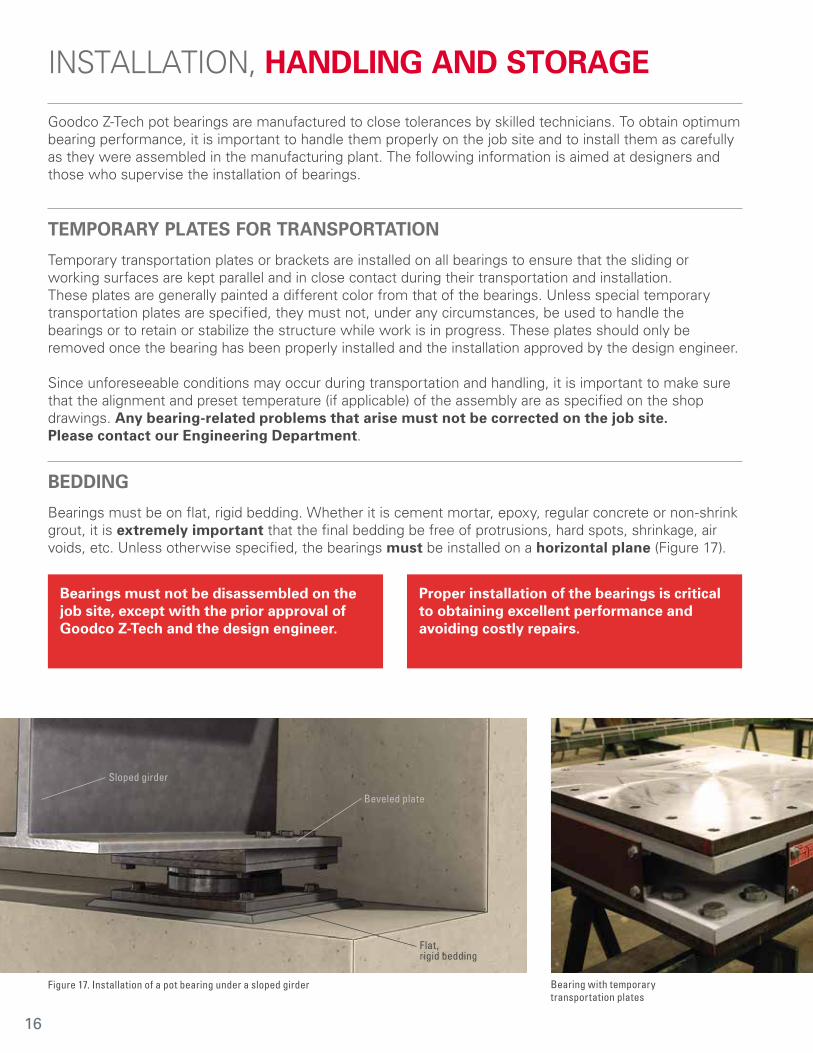
Bearings must not be disassembled on the job site, except with the prior approval of Goodco Z-Tech and the design engineer.
Proper installation of the bearings is critical to obtaining excellent performance and avoiding costly repairs.
Flat, rigid bedding
Sloped girder
Beveled plate
INSTALLATION, HANDLING AND STORAGE
Goodco Z-Tech pot bearings are manufactured to close tolerances by skilled technicians. To obtain optimum bearing performance, it is important to handle them properly on the job site and to install them as carefully as they were assembled in the manufacturing plant. The following information is aimed at designers and those who supervise the installation of bearings.
TEMPORARY PLATES FOR TRANSPORTATION
Temporary transportation plates or brackets are installed on all bearings to ensure that the sliding or working surfaces are kept parallel and in close contact during their transportation and installation. These plates are generally painted a different color from that of the bearings. Unless special temporary transportation plates are specified, they must not, under any circumstances, be used to handle the bearings or to retain or stabilize the structure while work is in progress. These plates should only be removed once the bearing has been properly installed and the installation approved by the design engineer.
Since unforeseeable conditions may occur during transportation and handling, it is important to make sure that the alignment and preset temperature (if applicable) of the assembly are as specified on the shop drawings. Any bearing-related problems that arise must not be corrected on the job site. Please contact our Engineering Department.
BEDDING
Bearings must be on flat, rigid bedding. Whether it is cement mortar, epoxy, regular concrete or non-shrink grout, it is extremely important that the final bedding be free of protrusions, hard spots, shrinkage, air voids, etc. Unless otherwise specified, the bearings must be installed on a horizontal plane (Figure 17).
Figure 17. Installation of a pot bearing under a sloped girder Bearing with temporary transportation plates
16

It is important for bridge designers to allow enough clearance for jacking the structure; otherwise this operation could prove to be very costly.
INSTALLATION, HANDLING AND STORAGE
CAST-IN-PLACE CONCRETES
Proper measures must be taken to ensure that the bearings are not damaged by the formwork or contaminated by the concrete. The interface between the sole plate and the formwork must be protected and sealed.
Given the loading effect of a wet concrete mass, the upper sub-assembly should be supported to prevent the rotation and distortion of the plate. Upper sub-assemblies with stainless steel sliding on PTFE are especially vulnerable in this regard.
PRESETTING
If presetting of the bearings is needed due to certain field operations that can cause large movements, it should be specified as a requirement and should only be carried out in our manufacturing plant prior to shipping.
FIELD WELD
If the bearings must be subjected to field welding operations, particular care must be taken to protect them against sparks and burrs. Welding should also be controlled in order to prevent excessive heat transfer to the elastomeric pad and PTFE components. Only welding procedures approved by the competent authorities must be performed.
BEARING REMOVABILITY
Where possible, bearings must be designed to be removable. Standard Goodco Z-Tech pot bearings are removable. However, this feature should be included in the contract specifications.
BEARING IDENTIFICATION
Black markings are used to identify each bearing. The arrow painted on the sole plate indicates the longitudinal direction of the bearing.
If necessary, a typical layout plan can be included with the shop drawings to enable the contractor to identify the exact location of each bearing.
Bearing for the Duplessis Bridge Trois Rivières, QC
17

HANDLING AND STORAGE
Under normal working conditions, Goodco Z-Tech pot bearings are protected from contamination by an effective sealing system. For shipping purposes, they are securely strapped to a wood pallet, wrapped and carefully loaded onto a truck. It is very important to unload and handle the bearings with great care and to store them securely in order to avoid contaminating or damaging any of the bearing components.
PROTECTION
Pot bearings are composed of materials and coated with finishes that are sensitive to contaminants. It is important to protect the bearings against the effects of operations causing projections. The effects of such operations as welding, grinding,sandblasting, spray painting, shotcreting, sawing, flame cutting, compressed air cleaning, pressure washing and high pressure water blasting could damage or contaminate the bearings and undermine their performance and durability.
INSTALLATION, HANDLING AND STORAGE
CHECKLIST FOR INSTALLING BEARINGS
DO’S:
1. Handle the bearings with care and, where required, use the proper type of crane.
2. Store the bearings in a clean, dry area.
3. Ensure that the bearings are installed at the exact location and in the correct orientation.
4. Ensure that the bearings are installed on flat, rigid bedding before the design loads are applied.
5. Ensure that the bolts and anchors are uniformly tightened.
6. Repair any area of the protective coating that was damaged during transportation, handling or installation.
7. Protect the sliding surfaces during in situ concreting.
8. Keep the bearings and the surrounding areas clean.
9. Remove any temporary transportation plates before the bearings are put into service.
10. Ensure that the upper sub-assemblies are supported during in situ concreting.
DON’TS:
1. Disassemble the bearings on the job site.
2. Leave the bearings uncovered.
3. Install any bearing that shows signs of damage.
4. Attempt to make repairs without the approval of Goodco Z-Tech.
5. Use the temporary transportation plates for lifting.
Figure 19
Figure 20
18

QUALITY COMMITMENT
We maintain a rigorous quality control program to meet the most exacting requirements of our customers.
Our team of engineering and technical drafting professionals master tools such as AutoCAD and SolidWorks.
Our products are designed and manufactured by an experienced and qualified team with state-of-the-art equipment.
We are equipped to perform the most complex and commonly requested tests to guarantee the conformity of our products.
Quality Control
CAD Drafting, Engineering In-House and Laboratory Testing
Fabrication
QUALIFICATIONS W59: Welded Steel Construction (Metal Arc Welding)
W47.1, Division 1: Certification of Companies for Fusion Welding of Steel Structures
W186: Welding of Reinforcing Bars in Reinforced Concrete Construction
--
QUALIT Y CERTIF IED
STEEL STRUC TURES
19

BETTERBUILDING BRIDGESWith more than 60 years of experience, Goodco Z-Tech is the leading Canadian fabricator of structural bearings and expansion joints. Relying on the knowhow of our highly skilled team and state-of-the-art equipment, Goodco Z-Tech designs and fabricates a broad range of products for highway and railway bridges, and other structures. Goodco Z-Tech works in close collaboration with Canam-Bridges, a North American leader in the design, fabrication and construction of steel bridges.
© C
anam
Gro
up In
c., 2
016
Last
mod
ified
on
12/2
016
Prin
ted
in C
anad
a
Quebec807, rue Marshall, Suite 100 Laval, Quebec H7S 1J9
Ontario1739 Drew RoadMississauga, Ontario L5S 1J5
450-786-13001-800-361-3510canambridges.com
Canam-Bridges is a division of Canam Group Inc.