
POSTALE 2008 Proceedings(1)
310
Policies, Statutes & Legislation in Mines POSTALE 2008 Editors Achyuta Krishna Ghosh Santosh Kumar Ray Aditya Kumar Patra
-
Upload
nutan-prakash -
Category
Documents
-
view
151 -
download
12
Transcript of POSTALE 2008 Proceedings(1)

National Seminar on Policies, Statutes & Legislation in Mines POSTALE 2008 Policies, Statutes & Legislation in Mines
POSTALE 2008
Editors Achyuta Krishna Ghosh
Santosh Kumar Ray Aditya Kumar Patra

National Seminar on Policies, Statutes & Legislation in Mines POSTALE 2008
Proceedings of the NATIONAL SEMINAR held on Dec 20-21 2008 at Central Institute of Mining and Fuel Research, Dhanbad, India
POLICIES, STATUTES & LEGISLATION IN MINES
POSTALE 2008
Organised by CENTRAL INSTITUTE OF MINING & FUEL RESEARCH
DIRECTORATE GENERAL OF MINES SAFETY NATIONAL INSTITUTE OF SMALL MINES
Edited by ACHYUTA KRISHNA GHOSH
SANTOSH KUMAR RAY
ADITYA KUMAR PATRA CENTRAL INSTITUTE OF MINING & FUEL RESEARCH
Dhanbad, Jharkhand, INDIA

POSTALE 2008
Organising Committee
• Mr. M. M. Sharma, Chairman Director General of Mines Safety, Dhanbad (Jharkhand)
• Dr. Amalendu Sinha Director, Central Institute of Mining & Fuel Research, Dhanbad (Jharkhand) Chairman, Core Committee, POSTALE 2008
• Mr. S. J. Sibbal Deputy Director General of Mines Safety, Directorate General of Mines Safety, HQ, Dhanbad (Jharkhand)
• Mr. Achyuta Krishna Ghosh Senior Deputy Director, Central Institute of Mining & Fuel Research, Dhanbad (Jharkhand) Convener, POSTALE 2008
• Mr. B. P. Singh Director of Mines Safety (S&T), Directorate General of Mines Safety, Dhanbad (Jharkhand) Coordinator, POSTALE 2008
• Mr. D. K. Das Member, Executive Committee, National Institute of Small Mines, Kolkata (W.B.)
• Dr. (Mrs.) Arati Nandi Head (R&D), National Institute of Small Mines, Kolkata (W.B.) Co-Convener, POSTALE 2008
• Dr. Mohan Prasad Senior Deputy Director, Central Institute of Mining & Fuel Research, Dhanbad (Jharkhand)
• Mr. Santosh Kumar Ray Scientist, Central Institute of Mining & Fuel Research, Dhanbad (Jharkhand) Co-Convener, POSTALE 2008
• Dr. Aditya Kumar Patra Scientist, Central Institute of Mining & Fuel Research, Dhanbad (Jharkhand) Co-Convener, POSTALE 2008
Advisory Committee
• Mr. S. L. Chakraborty, Chairman Former Managing Director, West Bengal Mineral Development & Trading Corp. Ltd. Founder, National Institute of Small Mines, Kolkata (W.B.)
• Prof. A. K. Ghose Former Director, Indian School of Mines, Dhanbad, (Jharkhand) Founder Member, National Institute of Small Mines, Kolkata (W.B.)
• Prof. S. P. Banerjee Former Director, Indian School of Mines, Dhanbad (Jharkhand)
• Prof. B. B. Dhar Former Director, Central Mining Research Institute, Dhanbad (Jharkhand) Former President, National Institute of Small Mines, Kolkata (W.B.)
• Mr. S. N. Padhi Former Director General of Mines Safety, Dhanbad (Jharkhand)
• Mr. N. C. Saxena Former Deputy Director, Central Mining Research Institute, Dhanbad (Jharkhand) Retd. Professor, Indian School of Mines, Dhanbad (Jharkhand)

POSTALE 2008
• Dr. S. K. Sarkar Former Deputy Director, Central Mining Research Institute, Dhanbad (Jharkhand) Secretary General, Society for Mining Research, Sustainable Development & Environment, Kolkata (W.B.)
• Prof. D. D. Misra Former Director, Central Mining Research Institute, Dhanbad (Jharkhand) Former President, National Institute of Small Mines, Kolkata (W.B.)
• Mr. P. R. Mondal Adviser (Project), Ministry of Coal, Govt. of India, New Delhi
• Mr. N. L. Rungta Director, Rungta Mines Private Ltd., Chaibasa, (Jharkhand) Former President, National Institute of Small Mines, Kolkata (W.B.)
• Mr. Ch. Divaker General Manager (Jharia Collieries), Tata Steel Ltd., Jamadoba, Dhanbad (Jharkhand)
• Mr. P. Prasad General Manager (Chasnalla Collieries), Steel Authority of India Ltd., Chasnalla, (Jharkhand)
• Mr. D. S. Nigam General Manager (R), ISP, Steel Authority of India Ltd., Kulti, (W.B.)
• Prof. D. C. Panigrahi Head, Department of Mining Engineering, Indian School of Mines University, Dhanbad (Jharkhand)
• Prof. J. Bhattacharya Head, Department of Mining Engineering, Indian Institute of Technology, Kharagpur (W.B.)
• Prof. U. K. Dey Head, Department of Mining Engineering, Bihar Institute of Technology, Sindri (Jharkhand)
Patrons • Mr. Arun Kumar
Executive Director, Petroleum Conservation Research Association, New Delhi Secretary, Oil Industry Development Board, New Delhi
• Mr. S. Das CEO, Mining & Allied Machinery Enterprises, Sanctoria, (W.B.)
• Mr. S. Chakraborty Chairman cum Managing Director, Eastern Coalfields Ltd., Sanctoria (W.B.)
• Mr. T. K. Lahiri Chairman cum Managing Director, Bharat Coking Coal Ltd., Dhanbad (Jharkhand)
• Mr. R. Saha Chairman cum Managing Director, Central Coalfields Ltd., Ranchi (Jharkhand)
• Mr. S. Narasing Rao, IAS Chairman cum Managing Director, Singareni Collieries Co. Ltd., Kothagudem (A.P.)
Core Committee
• Dr. Amalendu Sinha Director, Central Institute of Mining & Fuel Research, Dhanbad (Jharkhand) Chairman, Core Committee, POSTALE 2008
• Mr. Achyuta Krishna Ghosh Senior Deputy Director, Central Institute of Mining & Fuel Research, Dhanbad (Jharkhand) Convenor, POSTALE 2008

POSTALE 2008
• Mr. B. P. Singh Director of Mines Safety (S&T), Directorate General of Mines Safety, Dhanbad (Jharkhand) Coordinator, POSTALE 2008
• Dr. (Mrs.) Arati Nandi Head (R&D), National Institute of Small Mines, Kolkata (W.B.) Co-Convenor, POSTALE 2008
• Dr. Mohan Prasad Senior Deputy Director, Central Institute of Mining & Fuel Research, Dhanbad (Jharkhand) Treasurer, POSTALE 2008
• Dr. Pramod Kumar Arya Deputy Director, Central Institute of Mining & Fuel Research, Dhanbad (Jharkhand)
• Mr. Santosh Kumar Singh Scientist, Central Institute of Mining & Fuel Research, Dhanbad (Jharkhand)
• Dr. M. S. Alam Scientist, Central Institute of Mining & Fuel Research, Dhanbad (Jharkhand)
• Mr. Subhasis Biswas Scientist, Central Institute of Mining & Fuel Research, Digwadih, Dhanbad (Jharkhand)
• Mr. Santosh Kumar Ray Scientist, Central Institute of Mining & Fuel Research, Dhanbad (Jharkhand) Co-Convenor, POSTALE 2008
• Dr. Aditya Kumar Patra Scientist, Central Institute of Mining & Fuel Research, Dhanbad (Jharkhand) Co-Convenor, POSTALE 2008
• Dr. G. M. Prasad Scientist, Central Institute of Mining & Fuel Research, Dhanbad (Jharkhand)
• Dr. A. K. Singh Scientist, Central Institute of Mining & Fuel Research, Dhanbad (Jharkhand)
• Mr. Dilip Kumbhakar Scientist, Central Institute of Mining & Fuel Research, Dhanbad (Jharkhand)
• Mr. Prabhat Kumar Mondal Scientist, Central Institute of Mining & Fuel Research, Dhanbad (Jharkhand)
• Mr. Ashis De Exec. Engineer, Central Institute of Mining & Fuel Research, Digwadih, Dhanbad (Jharkhand)
• Mr. D. Rath Purchase Officer, Central Institute of Mining & Fuel Research, Digwadih, Dhanbad (Jharkhand)
Volunteers
Ms. Sneha Rai1 Ms. Joyitta Banerjee1
Mr. Vikas Kumar Sinha1 Mr. Vivek Kumar1
Mr. Kumar Kunal Nanbetiya1 Mrs. Twisha Adhikary**
Mr. Ranjit Chaurasia1 Mr. Debjit Pal** Mr. Anand Prakash1 Ms. Anjali Kumari**
1 Research Fellow, CIMFR, Dhanbad ** Research Fellow, NISM, Dhanbad

POSTALE 2008
FOREWORD Mining, the only basic industry beyond agriculture and the mother of all other industries as well, comprises the extraction of non-renewable natural resources of ores, minerals and fossil fuels from their natural abodes in the crust of Mother Earth. As a result, the damage of nature is an inevitable and very often a discernible consequence of any mining activity. In addition, even a little careless-ness in it in any way, aggravates the damage by many folds. Moreover, mining is commonly per-ceived as a hazardous business as its accidents often cost lives and assets.
At the same time, today human civilization cannot survive without mining. Kautilya (also known as Chanakya & Vishnugupta, c. 340-293 BC), the father of modern economics and political science who first laid down the basic rules of governance and fiscal management of a state in his ARTHASHASTRA, highlighted the significance of mining in a society and stated, “Mines are the source of treasury, from treasury comes the power of Government”. This paradox has been nicely described by Joseph Wood Krutch (1893-1970) a noted American literary naturalist, a teacher, a critic, a biographer, an editor, a journalist, and a public speaker, as, “If people destroy something replaceable made by mankind, they are called vandals; if they destroy something irreplaceable made by nature, they are called developers”.
“To waste, to destroy, our natural resources, to skin and exhaust the land instead of using it so as to increase its usefulness, will result in undermining in the days of our children the very prosperity which we ought by right to hand down to them” [Theodore Roosevelt, Message to Congress on 3rd December, 1907]. Thus, to control the wastage of mineral resources confirming their appropriate conservation, to ensure safety in mines and their surroundings, to minimise and mitigate the mutila-tion and pollution of nature caused by mining and mineral processing, as well as to meet the social demands with fulfillment of economic boundary conditions, we formulate and put into practice differ-ent policies and statutes that call for reviews, amendments and reforms from time to time in tune with the new scientific and technological discoveries, inventions and innovations, and the changes in economic and social scenario through elaborate and open discussions and debates among the stakeholders of mining industry covering all the sections of mining society.
Mining stands apart from any other industries not alone for its seemingly damaging look, but also for several other aspects, and thus needs a special attention on this issue. Thus, to provide a common platform for Indian mining community for this discourse, CENTRAL INSTITUTE OF MINING & FUEL RESEARCH (CIMFR), [formerly Central Mining Research Institute (CMRI)], with DIRECTORATE GENERAL OF MINES SAFETY (DGMS) and NATIONAL INSTITUTE OF SMALL MINES (NISM), held a National Seminars on Policies, Statutes and Legislation in Small and Medium Mines in 2002 [POSTALE 2002], and again on Policies, Statutes and Legislation in Mines in 2005 [POSTALE 2005].
In the current milieu, when several states have drawn up their mineral policies, major changes in mining statutes are in the offing, prominent modifications have been made in the principle and pro-cedure of appraisal of environmental impacts, National R&R Policy (NRRP 2007), Jharkhand R&R Policy (JRRP-08) and R&R Policy of Coal India Ltd. have been announced, Hazardous Materials (Management, Handling & Transboundary Movement) Rules, 2007 is coming up, and several old controversies and conflicts on various policies, statutes and practices are still left unresolved, we feel that the time is now ripe enough to hold a third such seminar in 2008.
Therefore, CIMFR, DGMS and NISM have now come together again to organise the NATIONAL SEMINAR ON POLICIES, STATUTES & LEGISLATION IN MINES 2008 [POSTALE 2008],, the third one in the series, at CIMFR in Dhanbad on December 20-21, 2008.
The organisation and success of this seminar is due mainly to the valuable contributions from the authors, the efforts of the organising institutes and the members of different committees and many other individuals. On behalf of the POSTALE 2008 Core Committee I am thankful to every indi-vidual who has contributed in some form or other in materialization of this seminar.
CIMFR, Dhanbad December 12, 2008
AMALENDU SINHA DIRECTOR, CIMFR
CHAIRMAN, CORE COMMITTEE POSTALE 2008

POSTALE 2008
FROM THE CONVENOR’S DESK…
PROLOGUE
Mining is the only basic industry other than agriculture and farming that provides natural resources to mankind for its survival and development, but unlike the latter its reserves are non-replenishable. In consequence of a few unique virtues and vices, mining stands apart from all other industries. Although it has some strong nega-tive attributes, it can never be substituted as it supplies the basic raw materials for all other industries that in turn meet our day-to-day needs. This single reason is good enough to establish the claim of this industry for a very special attention and specific treatment in all aspects in general, and on the policies, statutes and legisla-tion in particular, as they provide the prime guidelines for modus operandi for this industry.
Let us have a glance at those distinctive features to set the milieu for further deliberations.
MAN & MINE
As every mine has a limited non-renewable geological reserve, whether large or small, unlike any other industry, the life of a mine bears striking resemblances to human life. A mine is conceived through the process of discovery an ore or mineral deposit, its exploration, feasibility evaluation and finally long-term planning of working.
It is followed by a period of gestation. An entry is made to the deposit by making a box cut, or sinking shafts, or driving inclines/declines/adits. The deposit is developed by excavating roadways and simultaneously building up other infrastructures to strengthen it to comfortably handle its busi-ness with techno-economic sustainability while it would come in production. It is like a foetus growing to a baby in its mother’s womb.
In time, a baby is born after its adequate growth in mother’s womb. Likewise, a mining project, being suitably equipped and sufficiently developed, starts producing and thus turns into a full-fledged mine. In other words, a new mine is born.
With time it gradually grows with its production and productivity steadily improving with expan-sion and improvement of infrastructures, as a baby grows through childhood and adolescence with proper care, education and training. Finally, the mine attains its peak performance level and enjoys its youthful run over a period.
Then comes its middle age with its yield and efficiency slowly declining and its maintenance and overhead costs gradually rising, just like the expenses on family maintenance and medical bills go up for a man in his middle age. In the process, both, man and a mine, survive a few small and big techno-economic jolts by virtue of its long experience.
Just as old age creeps in a man’s life and finally ends at death, with the passage of time, depending on its geological reserve and technoeconomic boundary conditions, a mine gets old and starts shrinking, initially little by little but gradually at a faster rate, till the last bit of reserve is mined when it breathes its last.
Statutorily speaking, the last rites of a mine are performed by closing it. In case of human being, this is done following some predefined traditional norms and legal procedures. For mines, it should be done following scientific and systematic meth-ods of mine closure.
A few weeks ago I had an opportunity to visit the iron ore mining belt in Chaibasa-Barbil region. The broken, dusty roads of that area, which used to be overcrowded round the clock and often jammed with dumpers and trucks plying with overloads of iron ore, were lying empty with little traffic movement. Many small and medium quarries were out of operation with their machines and equipment standing still and silent. Harsh impacts of global fiscal meltdown, leading to drastic drop of mineral price and sudden fall of demand in market, were obvious all over the place.
The techno-economically strongest mines have largely absorbed this shock but their yield has gone down; the medium ones are palpitating for the lack of nourishment;

POSTALE 2008
and the weakest ones have already slipped into coma. In course of time, as the period of economic recession will be over, some of the mines currently out of operation will come back to life, but many of the smallest and weakest ones may not ever operate again. Does it not resemble what we are likely to see in a society having people from wide economic cross-section if it be hit by a wide-spread epidemic or famine?
Likewise, if we delve deeper into it, we may perhaps find that each and every major event or phase in the life of any mine has a parallel in human life.
MINING & OTHER INDUSTRIES
At this juncture one may ask how the cessation of operation in those mines, whether for the time being or for-ever, is different from the so-called temporary closure of the Dunlop, the recently-reopened once-renowned tyre manufacturing company in West Bengal, owing to the same economic slump. In fact, during my above-mentioned visit, as I expressed the resemblance of the current status of iron ore mining of that region with so-ciety, someone raised this point.
It is right that many industries all over the world have recently been closed down due to the collapse of global market, and so have these mines as well. And, like these mines here, some of those industries will also spring back to life once the dark days are over, but some will be lost permanently.
When an industry, whether mining or non-mining, loses its economic viability and lacks appropriate tech-noeconomic backup to update its state of art, it is shut down. Of course, this supposition does not hold good for the Indian public sector industries including the nationalised mining industries, many of which continue to run even after incurring continuous loss.
Nevertheless, there is a basic difference in the revival of those non-mining industries with that of a mine even in the situation of an economic setback. For a non-mining industry the revival would solely depend on the availability of economic support for the maintenance of the existing system in the lean period, and/or for the technical up-gradation of the system in the post-recession period as and when needed. If this backing is avail-able, that industry may run again for years to come, provided its products have not become obsolete.
On the other hand, for a mine that has now gone out of production because of non-profitability, the availability of fund will not be the only criterion for its revival as the market would shoot up in future. The mineable re-serve the then available in that given leasehold would play the key role.
The art and science of mining has developed over ages from man’s repetitive adventurous quests to unveil the secrets of nature below ground, and to unearth and acquire what he thought useful and valuable. At times these attempts have been proved to be fatal, either because of our ignorance, or due to our callousness or careless-ness. Moreover, mining unquestionably has degenerative effects on geological, geographical, environmental, ecological and socioeconomic setup of the site and its surroundings. As a result, mining is popularly known as an unsafe, highly accident-prone industry that degrades nature. Though these accusations do not appear to be untrue, but can we do without mining? Certainly, it is not. Then we should not overlook a few vital points about mining as well.
Mining is perhaps the only industry that yields some production even during its construction and development. A mine, even without its machineries and equipment, has a value much beyond the price of the land as long as it has enough mineable resource. While, a non-mining industry, which is not running and has no machinery and equipment in it, is simply evaluated in terms of the costs of the industrial land it covers.
A land deployed for any other industry barring agriculture and farming, is lost forever until and unless the sus-tainability of that system is totally upset by natural catastrophe, radical economic downfall or technological revolution. Otherwise, a non-mining industry can be run for an indefinite period by upgrading, modifying or changing the technology from time to time to maintain economic feasibility, and thus may retain a land for a long time that cannot be estimated. In case a technology or a product becomes obsolete, the whole industry may be replaced by a new and/or different one. An engineering workshop may well be substituted by a chemi-cal factory, or vice versa, on the same piece of land. That is why a land once marked for industrial purpose is practically lost forever for any other use. Lands used for urban habitation meets with the same fate and get detached from its original natural setting once for all.

POSTALE 2008
For mining, it is definitely not so. Like any other industry, a mine also holds certain amount of land as long as it runs; but contrary to them, a mine cannot be operated once its reserve is exhausted even with the best tech-noeconomic support. Thus mining does not retain its land perpetually. Ultimately it gives the land back; but how, and to whom?
MINING VIS-À-VIS POLICIES, STATUTES & LEGISLATION
To take care of mined out land, preparation of closure plan has been made an obligatory part of mining and environment management plans, but have we really developed any machinery to monitor whether it is being rightly followed? Though theoretically the reply is ‘yes’, practically it is a big ‘no’ in general, and for our big-gest mining industry – the coal mining industry, in particular.
The people in coal industry, especially those in public sector companies, still opine that a mine is not opened for closing it. As a result, we have many underground coal mines which are in dormant state, and millions of tonnes of coal are locked up in thousands of coal pillars in these mines. Ironically, many of them are developed in such fashions that they can never be recovered. To add to the misery, many of such temporarily closed or abandoned mines are waterlogged or in fire. They increase the risk of accident to their adjacent mine workings and will remain so if scientific policies are not honestly framed and devotedly executed to eradicate them. Ironically, while mining adjacent to a temporarily closed or abandoned working with high danger potential, we try to take precautionary measures in the running working to avoid accidents, but we hardly take any timely step to eliminate the possible causes of danger from the grassroots. There is no clear cut guideline for tempo-rary closure or abandonment, nor any statutory directive to prevent such things.
The fallacy lies in the fact that an underground mine operator needs statutory permission for opening a mine as well as for extraction of the deposit, but no permission is required to develop the mine. As a result, once opened an underground mine operator may develop his mine at his whim, without caring for the future scope of conservation of the resource. There are many subsurface mines that have been developed without having any clear idea of how to work it later for extraction.
Unfortunately, our policies and their practices are often governed by short-term political effects rather than by long-term scientific factors such as mineral conservation, economics of the state and the nation, socioeconomic development, environmental protection etc.
Illegal mining is another basic problem in several mining belts in the country. It is unsafe not only for its prac-titioners, but also for the locality where it is practised. In addition, it causes considerable loss of income to government, and being irregular and unsystematic, it wastes a lot of minerals. While in every area where illegal mining is practised, it is known to the mine operators, concerned statutory bodies and local administration, no one takes any initiative to prevent it. Everyone has his own alibi to evade the responsibility, though the real reason may be different. It may be noted that though illegal mining is done in very small scale at scattered, isolated spots in an area, it is generally remotely coordinated to unify the productions from various sites to finally make a single business involving considerable amount of money. The patrons and sponsors of illegal mining are usually people with social recognition for their money power and sometimes for political clout as well.
Many amendments in Mines Act 1952 have recently been proposed for the final approval of the Parliament. Much emphasis has been given to rationalise the penalties and procedure in tune with the present norms and economic standards. However, not a single word has been spelt about the crime and punishment for totally illegal mining activities that flout all laws.
Obtaining a mining lease and subsequently to have the right to open a mine are still time taking and tedious processes though some sporadic attempts have been made by the departments of mines of a few states and cen-tre to simplify them. But, no guideline is available at all to a mine operator for what to do with the land once a mine is exhausted and systematically closed. There are some models available that have been published in various papers. Some of them have been established abroad through successful implementation. However, no sincere attempt has so far been made in India to develop any such model that may suit our system. Although, in our country, for the wide range of minerals in different geographical and social settings with variety of mining systems prevailing, one single model may not fit everywhere, we need to make beginning somewhere.

POSTALE 2008
A mine operator with leasehold in a forest land normally finds it difficult to get land for compensatory foresta-tion. On the other hand, there are plenty of old, abandoned, orphan mines that lie uncared for, which can well be used for that afforestaion. This would largely help in regain the ecological balance of the area that has been missing so far for these abandoned, orphan mines. Unfortunately, complicacy in our present statutory system does not allow this to happen if the ownership of the running and the abandoned mines are different.
According to the capability and suitability of land, reclamation and closure of a mine should be planned keep-ing in view post-mining land use to provide livelihood for local people, especially for those who might lose their earning while the mine is closed. Duly reclaimed land of a closed mine can be used for many purposes like agriculture, farming, pisciculture, horticulture, cultivation of medicinal plants and/or plants for bio-fuel, wide spread market complexes and/or business centres, rural habitation or urban colonies with buildings lim-ited to two stories, places of tourists’ attraction like botanical and/or zoo gardens, entertainment parks, play-grounds and stadiums etc. Baseline data for this should be generated during pre-mining planning and relevant parameters may be periodically monitored.
Consequently, a system and culture also needs to be developed for transfer of mined out land to the people, either through government or directly, after systematic closure. Otherwise the fundamental objective of mine closure will be largely defeated.
Socioeconomic impact assessment (SIA) is now a statutory necessity for planning any new industrial project including mining. It is definitely a positive and progressive move. However, the assessment procedure needs to be tuned and modified for mining. Similarly, uniqueness of this industry calls for specific Resettlement & Re-habilitation (R&R) policy within the broad framework of National Resettlement & Rehabilitation Policy (NRRP) 2007.
Safety economics is an ignored issue in mine management. If one asks a mine management about this, one may get the whole account of how and how much money is being spent for safety in that mine. Management of few mines will only tell about the economic benefit effectively enjoyed them by safety practices. There is an urgent need of making every mine management aware of it. Preferably, every mine worker should also be made to understand the economic benefits of safety.
Small scale mining is another area that needs specific attention of the policy makers. Small scale mining should be categorically officially defined in with respect to Indian perspective. We cannot forget that many of the 70-odd minerals produced in India are obtained exclusively from small mines. Even artisanal mining is practised at places. Community coal mining in Meghalaya, marble mining in Makrana, Rajasthan are some of the many small scale mining belts where lack of safety is the prime problem. Definite R&D and HRD policies should be contrived and adopted for development of scientific and economically viable mining systems to improve safety, production and productivity of such mines, and to educate people in small scale mining business. Fi-nancial support in form of soft loans from banks at easy terms and certain tax rebates/exemptions may be made available to small scale mines as it is done in case of small scale industries.
There are many more areas which needs definite considerations from the standpoint of policies and statutes. However, a major area where we have essentially failed is to make the mining community aware of the con-cerned policies and statutes with proper interpretations and implications. At this juncture it sounds startling that Mines Act was first enacted in India more than a century ago in 1901.
MINING AND SOCIETY
However, despite much apathy from society, mining industry runs widely in all forms and scales in India pro-viding strong support to the national technoeconomic development within the framework of different statutes. It notably contributes to the economy of several states like Andhra Pradesh, Assam, Chhattisgarh, Goa, Guja-rat, Jharkhand, Karnataka, Maharashtra, Madhya Pradesh, Orissa, Rajasthan, Tamil Nadu, West Bengal etc., and will continue to do so for decades to come.
Any achievement of mining industry hardly ever finds a place beyond the corner in business and economics pages in a newspaper, that too in fine prints. But anything going wrong with a mine, whether an accident or a Supreme Court verdict to close it down due to environmental reasons, often makes a front page news in bold. How many common people really care to know about how the phenomenal rise in production of coal and iron ore in the country in this millennium has helped in the overall national growth? How many of us have bothered

POSTALE 2008
to take note of the fact that what role this industry plays in the fiscal stability to the country in these hours of global economic meltdown that has already put the advanced, rich and developed countries in back foot? Our journalists do not focus on it, but they never forget to mention the loss of revenue being incurred due to the collapse of mineral export market.
Notwithstanding its shortcomings and demerits, it is obvious that mining is an inseparable part of Indian indus-try for ages to come. Coal will remain the main source of energy for some more decades in future. Iron ore and limestone will continue to provide the basic raw materials for development and construction projects. Other mining industries will also provide vital mineral backup to the industries. Hence, with technologies improving and changing day by day, policies, statutes and legislation in Indian mines will always have scopes to improve through open discussion of all the stakeholders of this industry on a common platform of POSTALE.
POSTALE 2008
We started our journey in 2002, the centenary year of Directorate General of Mines Safety when we kept our area limited to small and medium mines. In 2005 the platform was made open for all the mines irrespective of their scale of operation. Today, in the last fortnight of 2008, we have gathered again to deliberate, discuss and debate on the same issues with a hope to come out with some new ideas and thoughts that may help the policy makers, the statutory bodies, the mine operators, the mine planners and designers, the researchers, the acade-micians, and other stakeholders of this industry in future to improve upon the existing systems.
We are thankful to all our delegates, guests, authors, sponsors and well wishers for their support in different forms. We are grateful to all those who have directly or indirectly supported the organisation of POSTALE 2008. We beg to be excused for any slippage in its proceedings as it had to be edited a bit hurriedly due to shortage time.
Lastly, we look forward to meet again in 2011.
CIMFR, Dhanbad December 12, 2008
ACHYUTA KRISHNA GHOSH CONVENOR, POSTALE 2008
SENIOR DEPUTY DIRECTOR, CIMFR SECRETARY GENERAL, NISM

National Seminar on Policies, Statutes & Legislation in Mines POSTALE 2008
CONTENTS Sl. No. Title Page No.
INAUGURAL ADDRESS 1 POLICIES, STATUTES & LEGISLATION IN MINES – SOME POINTS TO
PONDER M. M. Sharma
1
KEYNOTE ADDRESSES 1 ISSUES OF SAFETY IN OPEN-PIT MINES - QUO VADIS?
A. K. Ghose 3
2 SAFETY STATUTE FOR EXPANDING MINING INDUSTRY OF INDIA S. N. Padhi
7
3 R&R FOR MINING INDUSTRY NEEDS A SEPARATE NATIONAL POLICY N. C. Saxena
14
4 IMPACT OF CHANGING SOCIO-LEGAL SCENARIO ON LAND ACQUISITION FOR COAL MINING PROJECTS S. K. Sarkar
23
5 LEGISLATION & PROCEDURE FOR THE COMMENCEMENT OF A CAPTIVE COAL BLOCK H. L. Gupta
29
TECHNICAL PAPERS 1 POLICIES, LEGISLATIONS AND STATUTES FOR OPENCAST MINES OF
NEYVELI LIGNITE CORPORATION LTD, NEYVELI, TAMIL NADU A. R. Ansari
43
2 INNOVATIVE CONCEPT OF ENERGY SAVING BY USING FRP BLADES IN AXIAL FLOW FANS : A JOINT STUDY OF ISMU, TATA STEEL AND ENCON D. C. Panigrahi and D. P. Misra
55
3 OCCUPATIONAL HEALTH AND SAFETY MANAGEMENT STRATEGY S. K. Das
60
4 ENERGY CONSERVATION IN MINES – CASE STUDY OF MALANJKHAND COPPER PROJECT G. K. Pradhan and S. Jayanthu
68
5 FORMULATION OF GUIDELINES ON INSTUMENTATION VIS-À-VIS STRATA CONTROL CELL FOR UNDERGROUND COAL MINES S. Jayanthu , P. Parida, A. Bhagel and G. Sreenivasa Rao
78
6 THROTTLES TO SUSTAINABLE DEVELOPMENT OF SMALL-SCALE MINING IN INDIA S. K. Mukhopadhyay
92
7 RESETTLEMENT AND REHABILITATION – A SOCIAL RESPONSIBILITY A. Nandi
96
8 MINERALOGICAL CHARACTERISTICS OF PARTICULATE MATTER – A LEGAL REQUIREMENT FOR AIR QUALITY IN OPENCAST MINE A. Jamal and W. N. Kumar
103
9 LEGISLATIVE STATUS FOR VIABLE AND EQUITABLE BALANCE BETWEEN ENVIRONMENT AND DEVELOPMENT C. Chandna
106
10 DUST MANAGEMENT PLAN IN MINES V. Kumar
112

POSTALE 2008 11 REMOTE SENSING – A REVIEW OF ITS APPLICATION IN MINING AND
ALLIED INDUSTRIES A. Gaurav, and K. Dey
120
12 POLICY REQUIREMENTS FOR CLOSURE OF (ABANDONED) MINES R. Sundar Singh, V. M. S. R. Murthy, G. Singh, P. Natesan
127
13 CLOSURE PLANNING FOR MINES -- AN APPRAISAL D. K. Khanda and B. K. Pal
131
14 DESIGN OF LIGHTING SYSTEM IN SURFACE MINES – A NEW STRATEGY M. Aruna, Y. V. Rao and N. C. Karmakar
136
15 MINE SAFETY MEASURES IN INDIA WITH SPECIFIC REFERENCE TO INFORMAL COAL MINING M. K. Ghose
145
16 “LEADERSHIP AND CULTURE” THE KEY TO SAFETY PERFORMANCE T. K. Jena
154
17 A PROACTIVE MASTER PLAN FOR SUSTAINABLE AND ECO-FRIENDLY ENERGY SECURITY S. Sen and N. Moitra
156
18 AN INTRODUCTION TO SOCIAL IMPACT ASSESSMENT A. K. Patra, S. K. Ray, A. Kumari, M. Prasad, M. S. Alam and A. K. Ghosh
165
19 NEED FOR SEPARATE LEGISLATION AND INVESTMENT FRINDLY APROACH FOR UCG S. K. Ray, D. C. Panigrahi and A. K. Ghosh
176
20 OBJECTIVE OF NO SUBSIDENCE DAMAGE TO FOREST AREAS: MULTI-SEAM COAL EXTRACTION STRATEGIES AND A CASE-STUDY APPLICATION S. K. Singh, R. Bhattacharjee, A. Kushwaha, A. K. Singh and R. Singh
182
21 EXPERIENCE OF AN ATTEMPT OF DEPILLARING OF A COAL SEAM STANDING ON PILLARS BELOW AND ABOVE CAVED GOAVES OF TWO DEPILLARED COAL SEAMS A. K. Singh, A. K. Sur, A. K. Singh and S. Ram
193
22 A PROGRESSIVE MINE CLOSURE PLAN FOR AN OPENCAST LIME STONE MINE R. Trivedi, M .K. Chakraborty, A. G. Sangode and B. K. Tewary
202
23 SUPPORT GUIDELINES FOR DEPILLARING CAVING FACES IN INDIAN COAL MINES A. Kushwaha, S. Tewari and S. K. Singh
209
24 STRATA MONITORING IN LONGWALL MINES – STATUTORY PROVISIONS AND TECHNICAL COMPLIANCE G. Banerjee, D. Kumbhakar and K. P. Yadava
219
25 ROCK MASS CLASSIFICATION APPLIED IN INDIAN UNDERGROUND COAL MINES – A LEGISLATIVE NEED AND SCOPE FOR UP-GRADATION N. Kumar, P. Kumar, A. Paul, A. K. Singh and A. Sinha
228
26 DESIGN AND SAFETY REQUIREMENTS OF FLAMEPROOF ELECTRICAL EQUIPMENT FOR USE IN COALMINES OF INDIA R. K. Vishwakarma, A. K. Singh, B. Ahirwal , A. Kumar, N. Kumar and H.K. Mondal
232
27 EVALUATION OF MINE WINDING ROPES AND THEIR SAFETY USING NDT : A CASE STUDY D. Basak
238
28 PERFORMANCE OF RFID DEVICES IN UNDERGROUND MINES S. Kumari, V. Jha, B. Mahato, B. Kumar, L. K. Bandyopdhyay, S. K. Chaulya and
244

POSTALE 2008 P.K. Mishra
29 MINE CLOSURE OPERATION AND THE STATUTORY REQUIREMENT FOR PREPARING A MINE PLAN P. K. Arya, A. K. Ghosh and A. Sinha
254
30 TECHNOLOGY DRIVEN CHANGE IN SUPERIMPOSED DEVELOPMENT OF CONTIGUOUS SECTIONS OF A THICK SEAM FOR SINGLE LIFT WORKING OF ITS TOTAL THICKNESS R. Singh, P. K. Mandal, A. K. Singh and R. Kumar
258
31 TESTING OF PERMITTED EXPLOSIVES – SOME UNRESOLVED ISSUES S. K. Roy, R. R. Singh and R. Kumar
266
32 POST-MINING SUBSIDENCE IMPACTS SOIL FERTILITY IN DRY DECIDUOUS TROPICAL FOREST, INDIA N. Tripathi, R. S. Singh, K. B. Singh and B. K. Tewary
273
33 ENVIRONMENTAL IMPACT ASSESSMENT – AN INTEGRATIVE APPROACH TOWARDS CONSERVATION OF BIODIVERSITY R. S. Singh, D. Pal, M. K. Chakraborty and B. K. Tewary
280
34 PROBLEMS ON VARIOUS ASPECTS OF PLACER MINING IN INDIA AND SUSTAINABLE DEVELOPMENT STRATEGIES TO OVERCOME V. Jha and M. Sundararajan
291

National Seminar on Policies, Statutes & Legislation in Mines POSTALE 2008
INAUGURAL ADDRESS POLICIES, STATUTES & LEGISLATION IN MINES
– SOME POINTS TO PONDER
M. M. SHARMA Director General of Mines Safety, Dhanbad
Dignitaries on the dais and sitting in the audience, the distinguished delegates, members of the press, electronic and print media, ladies and gentlemen present in this auditorium, At the outset, on behalf of all the organisers, I take the privilege to cordially welcome you all in this Inauguration Ceremony of National Seminar on Policies, Statutes & Legislation, POSTALE 2008. I express my sincere gratitude to all of you for your response to our sincere effort to organise this Na-tional Seminar, the third in its series, with the express aim of providing a forum to all the stake-holders of mining industry to share their experiences and work towards finding out practicable solu-tions to lessen the disputes and controversies on policies & statutes and their implementations. I am really very glad to be here today amongst the doyens of the mining industry and to share my thoughts with the august gathering. It is a fact that the country as well as the mineral industry is poised for a big jump for" its growth in the years to come. With the liberalization of Indian economy, the whole industrial society is facing certain challenges and mining industry is no exception. The growth in the mining industry is envis-aged to be manifolds. This is going to create a more complex situation as far as mine safety and health issues are concerned. This will call for qualitative and quantitative change in formulation as well as enforcement of mine safety management system. New Mass production technologies are being introduced on a large scale and alternative mining technologies like CBM, CMM, AMM or Underground coal gasification etc. are also coming up. In metalliferous mining sector, Beach sand and Deep Sea Mining is also emerging as new field. These new mining technologies are adding some newer dimensions of occupational safety and health prob-lems in such mines. Existing Legislative provisions do not match with the newer technology. Stan-dard or safe operating procedures for the new methods or equipments are yet to be developed in certain cases, leading to unsafe operations. The existing safety management system must address these issues so that the challenges of these new dimensions of safety with introduction of new tech-nologies are dealt effectively Mining industry has been opened to the private entrepreneurs and lot of mines are being opened and operated by private operators. Lot of multinational companies are also entering' the Indian min-ing industry for extraction of mineral. Out sourcing of certain operations and equipment is also be-coming quite common in the large Public Sector or Private 'mines. But this is also adding some new dimension to the health and safety aspects of mining industry. Privatization and outsourcing can not be overruled in today's context. But these issues need special attention and a suitable well defined & structured interface is to be established between the principal employer and the contractor, defining the responsibility in terms of maintaining safety and occupational health of the contractor's workers. Environmental impact due to mining is a major issue today in the whole world because the impacts are quite significant and revealing. Awareness of the general mass against damage to environment has been increased and mining industry is under critical scanning. The Environment laws have be-come very stringent and the captains of the mining and mineral industry do not have any alternative than to go for eco-friendly mining. Mine closure plan, Rehabilitation and Resettlement policies are gaining significant importance. None the less the awareness about safety and health of mine work-ers has also increased and introduction of the concept of safety and disaster management by risk assessment is a need of the hour.

POSTALE 2008
2
Development of a more flexible regulation with a simple and easy process for amendment will be required to keep the regulation updated and keep pace with the changing need of the industry. In this direction, a gradual shift from the highly prescriptive legislation of the present to a goal setting legislation with built in mechanism for risk assessment and' formulation of Safety, Health and Envi-ronment Management Plan would serve the purpose better. I am happy to share with you that we are currently already in the advanced stage of the process for bringing about the necessary amend-ments to take care of some major contemporary realities of the mining industry.
Existing safety management practices shall be supplemented by applying risk assessment tech-niques for hazard identification and corrective actions and also for monitoring it at regular interval. This approach will integrate safety with the primary objectives of .the organization. Introduction of risk management as a tool for development of a good health and safety management system is a break through in the- traditional strategy. The system is an effective tool for improvement of health and safety scenario. This needs to be introduced at levels of operation, maintenance and other allied activities. To provide the legislative backing to this important concept of risk assessment & safety management, we are in process of incorporating this in the newly proposed Coal Mines Regulations which are currently under active consideration of the Government. I will not take much of your time at this moment as lot of speakers will deliberate on these issues. I
sincerely hope that this national seminar will address the emerging issues and trends in the mineral industry in the coming years. The sub-themes of this national seminar are rightly focused to these emerging trends. Further, I hope that with your active participation this seminar will be able to draw a meaningful conclusion while addressing the contemporary OSH issues facing the mining industry. Even if a single recommendation sees the day of light and really makes some positive contribution to the mineral industry, it will be a great job done. At the end I once more welcome you all and ask for making the proceedings of the Seminar a great success.

National Seminar on Policies, Statutes & Legislation in Mines POSTALE 2008
KEYNOTE ADDRESS ISSUES OF SAFETY IN OPEN-PIT MINES - QUO VADIS?
PROF. AJOY K. GHOSE, FNAE Former Director, ISM, Dhanbad
INTRODUCTION With global mineral production scaling new heights, thanks to the spurt in global demand for raw materials with escalating “minerals hunger” of a burgeoning global population, the aggregate produc-tion volume touched nearly 24 billion tonnes in 2007 with sands, gravel, crushed rock and dimension stones contributing to the largest share. Of this, some 70% was contributed by open pits which are becoming larger, deeper and increasingly more mechanized and automated. The new-era open pit mines represent today gigantic materials handling operations with large-scale environmental im-pacts, calling for a new order of safety culture. The dimensions of safety in open pit mines are, by and large, a miniscule vis-à-vis underground min-ing and yet workplace–related injury and death contribute to lost production and impact on employee morale and productivity. The number of fatal injuries per one million man hours worked(FIFR) in open pit mines has registered some new highs and in Indian mining sector in the recent past surpris-ingly the rate of fatal accidents in surface coal mines has almost become the same as belowground operations hovering around 0.4 fatalities per 1000 persons employed. In the United States, during 2006, open pit coal mines accounted for 6 fatalities, metal mines 1, stone, sand and gravel opera-tions had 10 fatalities and non metal open pit operations reported no fatalities (U.S.Department of Labour, 2006). In general, safety issues in open pit mines centre around stability of slopes, accidents due to blasting and handling of explosives and those attributed to vehicular movement and falling objects. Even if the problem dimension is not significant, it calls for a close look to help avoid any injury to workmen or destruction of equipment which could bring the mining activity to a standstill. Analysis of accidents in open pit mines in India reveal that dumpers/trucks contribute to over 70% of fatal accidents, with some 40% attributable to negligent and/or unauthorized driving. Likewise, rever-sal without spotter and non-provision of audio-visual alarm and crossing haul roads contribute to some 10-15% of fatalities. In terms of percentage of accidents at different sites, haul roads and as-sociated roads account for nearly 60% of all open pit mine accidents. Managing tyre-related acci-dents is yet another area of concern as they can affect the maneuverability of trucks and dumpers and in extreme cases explosion of tyres while being inflated have also been responsible for fatalities. All work environments do have an inherent risk and open pit mine environments are no exception. Accidents in open pit mines, in general, conform to Du Pont’s accident analysis statistics where some 96 per cent accidents could be attributed to unsafe acts. Unsafe acts are the proximate cause for blasting and vehicular accidents, while unsafe conditions underlie the hazards of slope failure, often attributable to systemic design failure. We shall examine in this presentation the broad gamut of issues of safety in open pit mines in gen-eral with focus on emerging techniques for upgrading safety. SAFETY MANAGEMENT IN OPEN PIT MINES The first step in safety management chain in open pit mines is hazard identification, followed by quantification. In open pit mines, the hierarchy of safety initiatives could rely on Hazard and Oper-ability Study (HAZOP) and Hazard Analysis (HAZAN). For quantifying the risks, a wide array of tech-niques including Fault Tree Analysis, Risk Ranking Matrix and Consequence Analysis are standard available tools that are made use of in many industries, but there is a dearth of reported studies in

POSTALE 2008
4
open pit mines using these techniques. Fig.1 shows the conceptual stages of a risk analysis algo-rithm. Both consequences and failure probability estimates are involved and these are each subject to uncertainty and they are combined to estimate risk. The critical step in the process flow chart is the hazard scenario anlaysis which raises the triplet of questions posed by Kaplan and Garrick:
What can go wrong ? How likely it is ? What are the consequences?
More recently, Kaplan has suggested yet another model to begin the analysis by using Anticipatory Failure Determination Approach. “If I wanted to make something go wrong, how would I do it ?” A fault tree provides an overview of the connectivity of the causes of failure. It indicates how the events contribute to system failure. Safety of tailings impoundments in open pit mines or the failure of dumps has also raised serious concerns as catastrophic failures have occurred with serious consequences. ADDRESSING BLASTING RELATED ACCIDENTS Blasting is one of the most potentially hazardous operations in open pit mines. Most of the accidents are due to flyrock and an inadequate blast exclusion zone. A major share, if not the leading cause of fatalities in open pit mines, could be ascribed to flyrock which could result in extensive and expen-sive damage to equipment and plant and stoppages in production. Rock thrown over an excessive distance from a blast is a hazard to equipment tyres and can cause unnecessary delays related to cleanup of the flyrock. Apart from flyrock, other blasting related incidents include truck explosion while transporting explo-sives( Hunter Valley,Australia,2003), lightning initiated explosion (in Australia), drilling into a charged hole, premature explosion of a detonating cord reel and all these have been critically reviewed(Sen and Downs,2008).Ground vibrations or air blast per se have not been identified so far as the proxi-mate cause of any accident in open pit mines. Major causative factors of flyrock events are insufficient burden, insufficient stemming and weak lay-ers or seams. Other contributory factors include poor blast design, and insufficient delays between rows besides use of secondary blasting such as pop shooting, which could be fully obviated by re-sorting to secondary rock fragmentation techniques with rock breakers. Powerful rock breakers, such as those from Fractum Technology (of Switzerland) with energy levels of 200,000 joules per stroke with a hammerhead impact frequency of 7 blows per minute, can handle effectively 20 tonne size rock boulders. Insufficient burden is the primary cause of flyrock out from the face, and there are several instances where rocks of very large size have been projected as far as 1 km or even longer distances, leading to fatalities. As flyrock can never be completely elimi-nated, a risk based approach to flyrock mitigation ensures that flyrock danger zone distances can be based on acceptable risk levels rather than the potential consequences of infrequent events. STABILITY OF OPEN PIT SLOPES- SAFETY DIMENSIONS Unexpected slope instabilities may impair the safety of personnel or impose the danger of burying mining equipment and resulting loss of production. Steeper slopes result in higher ore to overburden contributing to higher profitability. However, the steeper slopes may also contribute to risks of insta-bility which surface the dilemma to designers striving for steepest pit slopes consistent with stability. The design of a spoil bank for an open pit mine, likewise, must be based on such parameters of its elements, which allow following the accurate profile of the slope admissible in terms of stability for a specified depth.

POSTALE 2008
5
The criticality of slope design has called for a whole host of monitoring and surveillance techniques so that the onset of failures can be detected and personnel and equipment can be moved to safe zones before they get buried under a failing slope. Some remarkable case studies on the prediction of slope failure are available, including Bruce Kennedy’s near astrological prediction of the timing of slope failure at Chuquicamata! ( Hoek ands Bray, 1981). In general, open pit mines exhibit an assortment of slopes – from soil slopes near the surface, rock slopes, bench slopes, highwall slopes – each one of which needs to be analyzed by well-recognized techniques(CANMET,1977; Singh and Ghose,2006) and appropriate factors of safety used to pre-vent failures. Major geotechnical parameters which enter into such analysis include material proper-ties, rock structure, groundwater regime and external factors such as the effect of seismic shock. If stability analysis reveals that a given slope is potentially unstable and could damage plant, equip-ment or machinery or bury the ore reserves, it is prudent to take the following steps: • Monitor the stability of slopes • Identify the causes of instability • Redesign the slope to improve the factor of safety, if feasible. Use of supports to reinforce a slope for long term stability is rarely adopted, primarily on economic grounds. Monitoring of slopes has been honed into a state-of-the-art technology deploying total stations and GPS which offer excellent opportunities for detecting incipient slope movements so that appropriate steps for safe and timely withdrawal of men and equipment are possible. With the GPS-NAVSTAR, GLONASS and GALILEO satellite positioning systems, displacements of the order of sub-centimeter accuracy are within the realms of possibility. Addressing Miscellaneous Safety Issues For mitigating problems of fires, their detection and suppression on equipment, a host of products are commercially available, such as Kidde plc., and Ansul. The use of such vehicle-fire suppression system is mandatory in most countries. The planning of haul roads, their design and safety are also issue of high criticality. The machine-stopping distances for the fleet of vehicles is a primary consideration in road design and each vehicle in the fleet should be evaluated and road alignment adjusted to the machine with the longest stopping distance. Sight distance is another key element in the determination – it must be sufficient to allow the machine to safely stop before encountering obstructions or hazards. Minimum road width is also an important design issue as road width affects safe operating speeds and can help minimize tyre contact with safety berms and spilled rocks. Haul road safety provisions may include the addition of median or collision berms, escape lanes and dedicated small-vehicle roads. Appropriate signage on haul roads should be mandatory too. Reducing tyre wear through proper design and construction of haul roads at optimal grade, cross-slopes and super-elevation of corners maintains the proper weight distribution of the load and mini-mizes the lateral forces on truck tyres. Avoiding spillage is of paramount importance as about 75% of tyre failures are estimated to be caused by cuts from rocks and impacts with rocks.Use of mobile tyre handlers is yet another option for avoiding risks in handling large tyres. Of late, the acute short-age of tyres in the market has led to the adoption of best practices for tyre maintenance which also contribute in a large measure to safety. Innovative tyre monitoring systems show great promise for helping to improve tyre life. The technology involves the placement of a computer chip in the tyre that monitors the heat and pressure data as in Michelin MEMS tyre chip system. The data can be supplied to the truck operator or central monitoring system and can trigger action to reduce the tem-perature or provide adequate inflation. To improve tyre efficiency, inflation with nitrogen has been

POSTALE 2008
6
suggested. Use of nitrogen helps tyres to stay at a constant inflation pressure, thus increasing the tyre’s performance and decreasing the likelihood of tyre fires and flat tyres. In response to industry’s requirement for a safer, more productive and less stressful environment when using heavy vehicles and large mobile equipment, the deployment of Collision Avoidance System has become inescapable. This is especially relevant in hilly terrains, and during monsoons, when visibility becomes poor. Using rfid tagging, two way alarm systems have been evolved with colour video cameras and LCD display units which give both visual and audible warning. Reducing human error in driving heavy dump trucks, training on simulators is being recommended. Simulated training allows operators to be fully experienced and knowledgeable to the best effects. Immersive Technologies from Australia and Throughbred Technologies (Pty)Ltd. from South Africa provide a range of simulators to instill safety in operators. WHERE DO WE GO FROM HERE ? Managing safety in open pit mines and coping with the challenges ahead call for focused and con-certed efforts. Within the framework of an organizational vision, an integrated safety management approach has to be devised for all the safety issues enumerated above. As open pit mines become larger, deeper and increasingly more mechanized, the complexion and priority of safety issues are likely to change and new issues might emerge. Human factor analysis, for a given open pit mine de-sign configuration, assumes a new role and importance with new initiatives in operator task analysis, error analysis and preparedness for emergencies. Much however remains to be done vis-à-vis iden-tification of hazards, assessment of the risk and its ranking, controls and action plans, training and continuous improvement and finally auditing and review. As the open pit environment presents a kaleidoscope of dynamic changes, hazard elimination will have to focus on key result areas. New technological innovations may provide some powerful tools for hazard detection , but in the ultimate analysis, the goal of zero accident could be reached only through eternal vigilance. REFERENCES Anon., Mine Injury and Worktime, Quarterly, U.S.Department of Labour, Jan-Dec.2006. Sen,G.C., and Downs, G., 2008., An approach to addressing explosive related accidents by implementing strategic training, 2008
Coal Operators’ Conference, University of Wollongong, pp.251-259. CANMET, Pit Slope Manual, 1977, Canadian Center for Minerals & Energy Technology, Report No.77-13. Singh,R.N., and Ghose, A.K., 2006, Engineered Rock Structures in Mining and Civil Construction, Taylor & Francis, London. Li,A.J., et al.,2008, Stability charts for rock slopes based on the Hoek-Brown failure crierion, Int. Jl.of Rock Mechanics & Mining
Sciences,45,pp.689-700.

National Seminar on Policies, Statutes & Legislation in Mines POSTALE 2008
KEYNOTE ADDRESS SAFETY STATUTE FOR EXPANDING MINING INDUSTRY OF INDIA
SURENDRA NATH PADHI
Former Director General, DGMS, Dhanbad INTRODUCTION The earliest reference to “Mines Safety” in India is found in “Yajur Veda” (3000 B.C). It is stated there in that human beings should exploit the interiors of earth to take out Gold and other metals. How-ever, the persons engaged should be adequately educated in mining technology and mines safety. Kautilya (250 BC) had mentioned in his treatise “Arthasastra” that mining operation should be carried out under the supervision of a qualified and competent Mines Superintendent. However, in the mod-ern age, first safety statute was enacted under the British Rule and has gradually developed in Inde-pendent India. The Statute was reactive (based on experience) but the time has come to make it Proactive based on Risk Assessment and Safety Management Plan which will be essentially a goal setting performance based legislation with preventive and protective safeguards. HISTORY OF MINES SAFETY LEGISLATION OF INDIA Welfare and health of workers employed in mines are the concern of the Central Government (Entry 55, Union List Article –246). Occupational Safety & Health Legislation of the country has been en-acted in consistent with this constitutional obligation as well as the National Mineral Policy, 1993. One of the objectives of which is to ensure conduct of mining operations with due regard to safety and health of all concerned. Mines Act,1952 and Rules & Regulations framed there under have the basic objective of reducing risk of occupational diseases, casualty to persons employed & providing a better & safer working environment in mines. The first Mines Act was enacted in 1901 i.e. more than a century back. The past century may be conveniently divided into 3 parts, the first part is the half century up to 1950 i.e. till India attained in-dependence and became a republic. The second part i.e. the quarter; century from 1951 to 1975 witnessed the emergence of public sector. By 1975 Nationalization of major part of the mining includ-ing coal had been completed. The last quarter century, within a short span of 25 years has seen the excellent as well as the dismal performance by public sector and the emergence of the philosophy of LPG (Liberalization, Privatization and Globalization) towards the end of this quarter. Beginning of this century has started witnessing beginning of the process of disinvestment of public sector companies. LEGISLATION IN BRITISH INDIA The first Mines Act of 1901 was superseded by a new Indian Mines Act, 1923 and was finally re-placed by the Mines Act, 1952. Major changes were incorporated in this Act by amendments in the year 1959 & 1983. The first piece of safety legislation enacted a Century back was scanty compared to the size of the mining industry. The enforcement strategy has been also developed on the legislation structure. The main thrust was on “Policing” i.e. enforcement through legal sanction. The approach paid rich divi-dends in the initial period when there was a need to enforce the basic minimum safety legislation in a mining environment which was essentially small in magnitude and manual in process. The rate of accidents came down substantially as a result of enforcements mechanism. Further in view of limited scope of legislation and relative small magnitude of mining industry, it was possible for a small band of inspectors to enforce the same effectively.

POSTALE 2008
8
LEGISLATION IN INDEPENDENT INDIA – EARLY YEARS After India became a republic in 1950 and after Industrial resolution of 1956, demand for minerals increased and the magnitude of mining also increased at a rapid rate. Mining entered into deeper horizons and complex geomining locales. Mechanization slowly replaced manual operations which in turn increased the speed of operation. The industry oriented itself towards labour welfare and con-cern about mines safety attained new heights. Several committees were set up by the government to recommend necessary changes. Conservation of minerals became important. Health and Safety of workers started getting attention as never before and thus there were major shifts in policy and prac-tices. There was a galaxy of subordinate legislation like Mines Rules, 1955, Coal Mines Regulations, 1957, Metalliferous Mines Regulations, 1961 and Mines Vocational Training Rules, 1966 etc. In 1958 a major explosion at Chinakuri Colliery claiming 175 victims rocked the whole country when it was realized that the workers should be shifted from a position of an “object” to that of a “subject” and this paved the way for the first ever-Tripartite conference on Mines Safety on National Level. Thus started the era of safety conferences where major changes in mining statutes were mooted. LEGISATION IN INDEPENDENT INDIA – LATER YEARS The third stage of evolution of safety legislation came after the process of nationalization of major portion of mining i.e. coal mines were completed by 1975 and far reaching amendments were made in legislation. In fact, the Indian mining legislation started coming out of its infancy to attain adult-hood. In 1976, the conference on Organizational Aspects of Safety in Mines mooted the idea of workers participation in safety management through the twin instruments of safety committees and appointment of workmen Inspectors. The concept of Internal Safety Organization started receiving serious thought from this point of time. The slow transition from policing by mine inspectors to the era of self regulation started. Under the International Programme for Improvements of working condi-tions and environments (PIACT) of the ILO, a multi disciplinary team of safety experts visited the Indian mines in 1978-79. The recommendations of this team which became the background of fifth Conference on Safety in Mines (1980). This conference was another milestone in the history of mines safety in India. Among other things, safety policy for mining companies, adoption of improved technology, training and retraining of workers, internal safety organization, workers participation of safety management – foundation for all these major cultural changes were laid in this conference. The concept of self regulation had been strengthened in the subsequent safety conferences. The basic impact in formalizing the safety legislation was experience within the industry, directions given in national and international conventions, findings from research and development initiatives, rec-ommendations of the courts of enquiry, national safety conferences, reports of committees of expert groups appointed by the government & other agencies from time to time etc. A CRITICAL ANALYSIS The present legislation is alleged to be highly prescriptive as it lays down methodology of mining and permissions / relaxations / approvals are mandatory. The prescribed methodology may be out of synchronization with the emerging challenges and there is no flexibility. Interference and heavy de-pendence on the enforcing authority on safety decisions dilutes the responsibilities of the local man-agement which develops an attitude that compliance of legislation is the end by itself and does not thrive for continued improvement and best practice. Essentially, the mining safety legislation had been evolved based on the needs determined through experience and practice. In the future mining scenario, the demand for fossil fuel (solid, liquid, gase-ous) will continue to increase considering the increasing demand for energy. Similarly, mining of iron ore, bauxite and other minerals which are available in abundant in the country will likely to increase Globalization will continue and therefore there will be fierce competition between different players. Entry of multi-national will be accompanied with import of technology & mining operations will be highly specialized and flexible. The work force has to be highly skilled. The operations have to be highly productive with thrust on efficiency and cost benefit. There will be increasing deployment of

POSTALE 2008
9
contractors for carrying out non-routine as well as routine & regular operations. Small scale mining of minor minerals etc. will continue to remain traditional. A legislative structure of such type also can not effectively foresee the safety legislative requirements of the future. LEGISLATION – VISION FOR EXPANDING MINING INDUSTRY Future Requirement Any legislation mining or otherwise, has to be investor friendly in the context of breakage of global trade barriers. Mines Safety Legislation has to follow suit without sacrificing the interest of the work force. The legislation also needs to be broad based to cover high technology as well as small scale and traditional mining sector. Framing a Safety Legislation which will adequately meet the future safety requirement will call for a change from the traditional reactive approach of learning through experience to proactive approach through foresight. However, the future legislation also need to fit into the constitutional obligation and legal frame work of the country as well as the requirements of national and international conventions. International Guide Lines I.L.O convention No.176 and recommendation No.183 – Safety and Health in Mines (1995) which came into force in 1998 are the latest guide lines on the object – the minimum safety requirement against which all changes in the mine operations should be measured. The earlier guide lines I.L.O convention No.153 and recommendation No.164 on occupational Safety and Health and the working Environment (1981) & I.L.O convention No.161 & recommendation No.171 on occupational Health Services are also to be suitably followed. The convention advocates for hazard assessment, risk analysis and development & implementation of system to manage the risk. The convention also ad-vocates measures to encourage research and exchange of information on Safety & Health in mines, consultation between employers and workmen & rehabilitation and reintegration of workers who have sustained occupational injuries and illness. The convention also requires that suppliers of equipments, appliances and hazardous substances should ensure compliance with national stan-dards.
National Guidelines Guide lines may have to be also taken from national conventions. Ninth and tenth Conferences on Safety in Mines (Feb 2000 and November 2007) are the latest national guidelines, which advocates Risk Management as a tool for development of appropriate Health and Safety Management System, quality control (of equipments, appliances and materials) for improving safety, occupational Health surveillance, increasing effectiveness of workers’ participation in Safety Management, safety of con-tractor workers and in unorganized sector etc. The draft National Policy on OSH and proposal for framing an Umbrella Legislation on OHS are re-cent initiatives taken by Govt. of India in this direction for all occupations including mining. Emerging Legislation - An Outline Taking into consideration the fast changing, technology as well as entry of multinationals with thrust on competition the future legislation should be flexible to absorb the changing environment and keep pace with the fast changes that are sweeping the globe. This calls for proactive legislative provisions which is essentially a goal setting performance based legislation with preventive and protective safe-guards.

POSTALE 2008
10
PERFORMANCE BASED REGULATIONS Concept Performance based regulation is based on the concept of DUTY OF CARE which had its seeds in the Lord Robens Committee Report (UK-1970) on Safety and Health at work. In this report it was stated “Our present system encourages rather too much reliance on state regulation, and rather too little on personal responsibility and voluntary, self generating effort. This imbalance must be re-dressed. Reducing the sheer weight of the legislation should make a start. There is a role in this field for regulatory law and a role for government action. But these roles should be predominantly con-cerned not with detailed prescriptions for innumerable day-to-day circumstances but with influencing attitudes and with creating a framework for better safety and health organization and action by indus-try itself”. The report went on to say “The most fundamental conclusion to which our investigations have led us is this. There are severe practical limits on the extent to which progressively better standards of safety and health at work can be brought about through negative regulation by external agencies. We need a more effectively self-regulating system. This calls for the acceptance and exercise of ap-propriate responsibilities at all levels within industry and commerce. It calls for better systems of safety organizations, for more management initiatives, and for more involvement of work people themselves. The objectives of future policy must therefore include not only increasing the effective-ness of the State’s contribution to safety and health at work but also, and more importantly, creating the conditions for more effective self-regulation.” Thus the idea of general duty of care was born. Duty of care is a generic phrase used to describe the obligation of one party to be responsible for the safety and well being of another party due to the nature of the relationship that exists between the parties. Need Performance based regulation is to ensure that relevant legislation is in place to address the specific issues that will lay the foundation for a significantly improved work place environment on mine site e.g. • Specific training needs • A site specific safety policy • Site based programmes • The identification of particular national standards and the need for a systems approach Objectives The three key objectives are 1. To provide the necessary flexibility for operators to develop site-specific solutions to safety is-
sues: and 2. To create a Framework for Best Practice in Occupational Safety and Health Four major elements have been identified which characterize the occupational safety and health sys-tems of successful workplaces. All four elements are necessary to ensure that continuous improve-ment in occupational safety and health performance is achieved in the medium to long term. Those elements can be described in the following way. (a) The culture of a successful workplace (or organization) at all levels is one of commitment to oc-
cupational safety and health, of care for the well-being of everybody who works in the organiza-tion, and of a belief that workplace injury and disease can be prevented. The culture emphasizes quality in all aspects of the organization’s operations, including occupational safety and health (i.e. doing the job properly and avoiding superficially easy solutions to problems which do not rectify systemic deficiencies). The crucial factor in creating an occupational safety and health culture is the commitment of senior management, and communication of this commitment to all levels in the organization.

POSTALE 2008
11
(b) A successful workplace (or organization) has management systems geared to the practical and systematic implementation and maintenance of the occupational safety and health culture. The organization’s policies, working standards, procedures, training systems, level and types of su-pervision, purchasing decisions, maintenance schedules, communications systems and regular review mechanisms form part of the management system. The occupational safety and health management system is subject to regular and rigorous audits. Employees and all levels of man-agement are involved in the planning, development, implementation and review of the occupa-tional safety and health management system.
(c) The physical component of a successful workplace (or organization) has a working environ-ment, the hardware, purchased and installed with occupational safety and health considerations in mind. Hardware is operated and used according to the manufacturer / supplier instructions, and is regularly maintained as prescribed by them. Ongoing suitability for the task is regularly re-viewed in the light of occupational safety and health requirements, and hardware is replaced as necessary. The hardware includes plant, equipment, substances, materials and working condi-tions. Finance devoted to the purchase, maintenance and replacement of hardware is also a critical factor.
(d) The occupational safety and health culture of successful workplaces has a determining influence on decisions made regarding the organization’s hardware, particularly financial decisions. This culture exerts great influence on staff attitudes to co-operation and basic on- the - job (workplace level) decision-making and sets the tone of communication within the organization at its most basic level. The respect of the workforce can be so easily lost through a poorly developed cul-ture where the organization’s most precious asset is lost in the bottom line.
Thus the occupational safety and health culture in the workplace is clearly the most important ele-ment. 3. Encourage Mine Site Ownership of Safety: The legislation is designed to modify attitudes to safety by imposing behavioral requirements on mine operators that legislation is designed to encourage involvement at all levels of the organization. (a) It requires that an occupational safety and health policy be prepared and regularly reviewed in
consultation with the persons working at the mine. (b) That appropriately competent supervision is provided. (c) That appropriate training for all personnel is provided that everyone understands their duties and
that those working in the mine have the necessary skills and competence to carry out their du-ties.
(d) That the safety and occupational health needs of all persons are appropriately monitored. Key Features The key features of performance based regulation are Ownership - By encouraging personnel to be involved in the process, whether it be developing a mine site policy or documenting work procedures, those involved take ownership of the process and become involved and committed to its successful outcome. Best Practice - “Best Practice” embodies the notion that there are always better ways of doing things – that there is room for continual improvements. This concept overcomes the limitations of minimum standards which engender the “I’ve done enough attitude. Management Systems - The concepts of management systems, site safety policies, programmes and procedures, and their inter-relationship is shown below. The Safety System - Site Policy: The work environment in which all persons strive to work Programme: Establish the framework for achieving the environment

POSTALE 2008
12
Procedure: The way to do things Verification Process: Ensuring the system is working and improving Documented Safety Plan Duty of care on the Inspectorate - There is an implied need to ensure that a mine operator, in the absence of specific legislative requirements being identified, is provided with adequate information and counseling with regard to what is considered to be best industry standards in particular circum-stances. Risk Assessment - As the legislation is formulated on the premise that decisions on how to operate a safe mine rest at the mine site, it is apparent that a risk assessment approach needs to be adopted when examining and developing work procedures. Each operation will no doubt develop its own method of analyzing the risks involved but all will need to be systematic and to be effective, involve the personnel actually responsible for carrying out the task. Review Mechanisms - The manager of a mine should appropriately monitor the safety and occupa-tional health needs of persons working at the mine. This will require the introduction of regular audit, or review, procedures. • Audits / reviews will be initiated • by the mine and / or • by the Inspectorate The Chief Inspector of Mines (Director General of Mines Safety) has interpreted an appropriate level of monitoring as a process of self auditing or reviews that seek to verify the systems are in place and operating. In addition it will be appropriate that the Inspectorate initiate its own review procedures for operating mines. Removal of the Approval Process - There are no formal approvals required under the Mines Regulations as opposed to the many approvals by Inspectors required presently. The onus is on the manager to ensure that particular operating aspects are carried out safely. Complementary Information and Guidance : The Industry Standard - In seeking to fulfill their obligations and duty of care responsibilities, mine operators obviously require some guidance as to what issues should be addressed in relation to particular operating aspects. This guidance will be found by reference to one or all of the following: • relevant National Standards: • the National Guidelines for Safe Mining; and • the Industry / Safe Mining handbooks It is unlikely that operations conducted at variance with the relevant information supplied in the above documents or a recognized industry code of practice would be deemed to be operating safely. The Guidelines for Safe Mining and the handbooks are likely to be subject to a consultative review process between industry and the Inspectorate to reflect ongoing improvements in the industry stan-dard for particular activities. Subsequent editions of the Guidelines should be planned to incorporate feedback from interested parties. ROLE OF THE INSPECTORATE The removal of prescriptive regulations, and with them the notion of minimum standards, will change the role of the Inspectorate. The emphasis will now be on the management systems in place at a mine site and the Inspectorate will, if it is to demonstrate any leadership, need to provide information and guidance on the manner in which whole aspects of operations need to be systematically exam-ined and procedures adopted. There will be a greater need for discussion with operators to lead them to provide a satisfactory solution to a problem rather than a simple reference to a stated re-

POSTALE 2008
13
quirement. A partnership across the various sectors of the mining industry will develop. The Inspec-torate must provide leadership and direction while the mine operators must produce and implement the programs to achieve an improved safety environment at the workplace. The industry standard will be driven by the Inspectorate employing its skills and experience in judg-ing the appropriateness of the innovations that should flow from a more flexible legislation. Enforce-ment action will remain a very real and appropriate process where operators are not able to demon-strate that the necessary systems are in place. The Inspectorates’ over-riding responsibility will be to ensure that mine operators understand and are fully informed about the expectations of improve-ments that the new legislation implies. CONCLUSION The so-called prescriptive legislation had done its excellent work for almost a century. However, a need has arisen now for a set of legislation which will have a delicate balance between self Regula-tion, external inspection and policing inspection. This calls for a paradigm shift in the very safety cul-ture. However, the core legislative structure should remain intact within the frame work of the na-tional legal needs & should not be swayed by varying international standards and practices which may be brought in through entry of international players. Occupational Health & environment will come to the forefront. The role of enforcement agency will gradually shift from policing to that of administration of safety legislation. The enforcement agency will be a specialist body with a repository of information and a system to disseminate safety informa-tion, designing standard code of practices and developing standards for mining equipments and ma-terials. Because of the global need, development of a goal – setting legislation is inevitable. However, the transition period from prescriptive to goal setting legislation need be delicately balanced with a posi-tive mind-set of all concerned. REFERENCES Padhi S. N : 19th World Mining Congress (2003): Mines Safety in India – Control of Accidents and Disasters in 21st Century. Padhi S. N : Mines Safety Legislation in India in the context of International Scenario (2005) Padhi S. N : International Conference on Safety in Mines, Romania (1999) – Mines Safety in India, A perspective. Padhi S.N and Mishra N – Mining Laws – Safety Aspects (1996) Govt. of New South Wales (Australia): Department of Mineral Resources – Mine Safe (1996) Govt. of India : Ministry of Labour : Proceeding of Ninth Conference on Safety Mines (2000) International Labour Organisation Convention No.176 and Recommendation No.183 on Safety and Health in Mines (1995) Padhi S.N : Development of Mine Safety Legislation in India: Role of DGMS (1998) Denton Steve The Effective Management of Health and Safety in deep Coal Mines of Great Britain (2001) Hermanus Mavin Ann – Trends in occupational Health and Safety Policy and Regulations – Issues & Challenges in South Africa
(1999)

National Seminar on Policies, Statutes & Legislation in Mines POSTALE 2008
KEYNOTE ADDRESS R&R FOR MINING INDUSTRY NEEDS
A SEPARATE NATIONAL POLICY
N. C. SAXENA Former Head, CME, ISMU, Dhanbad
PROLOGUE The establishment of developmental and industrial activities for overall development of the regions and hence the nations calls for acquisition of land. The people living and sustaining their livelihood on such land areas are displaced and the people dependent on the land loose their livelihood. For taking care of such people rehabilitation and resettlement (R&R) packages are developed. These packages are a part of the Corporate Social Responsibility (CSR) of the mining companies. The pro-visions in these packages are as per the guidelines in the chosen R&R Policy. In the mining industry the R&R packages are developed as per the guidelines of the R&R Policies of the nation/state governments/mining companies. Some Policies have specific provisions for mining areas. Mining is different in many ways from the other industrial and development activities and the typicali-ties of the mining areas invariably are not taken into consideration in most of the Policies. Even the Policy of Coal India Limited (CIL), the largest coal mining company in the country, is inadequate. The author opines that the uniqueness of the mining activities and requirements of these areas at various stages of mining call for a National R&R Policy specifically dedicated to the mining sector. Brief outlines of such a policy are outlined hereunder. A CRITICAL ASSESMENT OF EXISTING R&R POLICIES
From the point of view of suitability of the R&R Policies of Government of India, Orissa, Madhya Pradesh and Coal India Limited, for the mining sector as a whole it is necessary to assess all the Policies in the light of the typical characteristics of the mining industry, which are as presented be-low. 1. Mining is a site specific activity as the minerals and fossil fuels are to be mined at the locations
of their existence. 2. Mining is only an intermediate use of land, because before mining and after the mineral/fossil
fuel resource is exhausted the land is of no use to the mining companies. 3. The people living in the mineral/fossil fuel bearing areas have no stake in the minerals and fossil
fuels. 4. The minerals and fossil fuels generally exist in forest and agricultural areas having a low level of
economy based mainly on the primary activities, i.e., forestry and agriculture. 5. The mineral and fossil fuel bearing areas in India are mostly in remote locations away from ur-
ban localities and are inhabited by the people mostly from scheduled tribes, schedules castes and other backward classes. The life style, traditions, culture and habits of these people vary from place to place and group to group.
6. The society of the mineral bearing areas may be facing various problems associated with low level of economy, e.g., poverty, malnutrition, etc.
7. Invariably all the labour force necessary for mining and associated activities is brought from out-side the mineral and fossil fuel bearing areas.
8. The infrastructure and civic facilities available in the mineral and fossil fuel bearing areas need quantum upgradation to facilitate mining and associated activities.

POSTALE 2008
15
9. Mining and associated activities are very high level economic activities compared to the level of the original activities in the mineral and fossil fuel bearing areas. When mining activities come to an end the level of the economic activities come down to near original level as the post mining activities are to be supported by the resources available after mining.
10. Mining and associated activities impact all the components of environment. Some of the impacts are beneficial to the society and some are harmful.
11. Both underground and opencast mines can be planned with proper concurrent or, if necessary, post mining reclamation of the land affected by the mining and associated activities. Such a practice has not been followed till now in the country.
12. In most mining situations the entire mineral/fossil fuel bearing land is never utilized at a time, i.e., simultaneously.
13. Mining is the only activity in which temporary displacement of the PAFs can be planned with the land taken being returned back with proper reclamation in an improved condition. Even the habi-tats of the people can be immensely improved with proper planning. During reclamation the land can be prepared for well defined uses, i.e., agriculture, forestry, building construction, making surface and underground water bodies, etc.
The above characteristics have not been taken into consideration in formulating the presently avail-able R&R Policies. These Policies have some shortcomings from the point of view of effectiveness in the mining areas. In fact the experience of CIL in the implementation of R&R in their mining areas can be taken as an indicator of these shortcomings. Coal India’s Experience CIL has been implementing R&R packages of PAFs for many decades. The company has a wealth of experience in this field. In order to fine tune its R&R efforts the company has been remodeling its R&R Policy with the experiences gained. For optimizing their R&R efforts CIL implemented a World Bank assisted Project, namely, Coal Sector Environment & Social Mitigation Project (CSESMP) in its 25 mining projects. The salient features of the implementation of this Project are outlined hereunder. (Bhattacharya 2003) The objective of the Project was to strengthen CIL’s capacity to deal more effectively with the envi-ronmental and social issues through implementation of Environmental Action Plans (EAPs), Reha-bilitation Action Plans (RAPs) and Indigenous People Development Plans (IPDPs) to make coal pro-duction environmentally and socially sustainable. The implementation of the project was adopted through a three pronged approach consisting of Policy Support, Institutional Building and Implemen-tation. Policy Support – Although CIL had an R&R Policy, which was facing many issues while implement-ing in the subsidiary companies, the Company after the inception of the Project adopted a compre-hensive Corporate Resettlement and Rehabilitation Policy under the guidance of the World Bank. This Policy was reviewed from time to time and changes were brought in with the experience gained. The company adopted a participatory approach towards implementation of the R&R for the PAFs. It was accepted that the PAFs are not only to be informed but also are to be consulted on matters of importance to the project and their entitlement or compensation and choice of R&R options. Institution Building – With the R&R Policy in place the company needed to have a dedicated group of executives for implementing the project through formulation of RAPs. Hence, an organization was established covering the entire decision making and implementing issues. Implementation - The first step towards implementation of the project was social impact assessment. This was done by assessing the socio-economic conditions of the PAFs and the impacts of land ac-quisition on them. The study of socio-economic conditions brought out details of social and economic status of the families who were to loose their means of livelihood and/or homestead. The data gen-erated were reviewed yearly to update them and make them more realistic.

POSTALE 2008
16
The second step consisted of the issue of photo identity cards to the PAPs/PAFs to facilitate imple-mentation and monitoring of the R&R assistance being given to them. The third step was the development of RAPs with focus on resettlement of the displaced PAFs and economic rehabilitation of the PAPs through income generating activities as pr income restoration plans to restore their income. The fourth step was the implementation of resettlement as per RAPs. The total number of PAFs dis-placed as a result of land acquisition due to mine expansion was 2,129. All these families were pro-vided with entitled resettlement benefits. The fifth step consisted of implementation of the income generation plan. The total number of PAPs eligible for this purpose was 10,214. Attempts were made to rehabilitate them economically by em-ploying them in the following activities. The reported monthly income of the PAPs in 2003 was about Rs 900-1,000/-. 1. Mine jobs 2. Jobs with contractors 3. Offering small contractual assignments after necessary training 4. Self employment through training 5. Arranging earning through land based income generation schemes Social Benefits Achieved - The following benefits were achieved by the implementation of the Pro-ject. (Bhattacharya 2003) 1. ‘Modified R&R policy brought a unified approach across the subsidiaries. It reduced the em-
ployment offer by the company to the land losers. 2. ‘Skill training and subsequent self-employment reduced the social crimes and coal pilferage, etc.
Hostile nature of the host community was also reduced. 3. ‘Offer of monitory compensation for resettlement became a popular package. It reduced the time
for resettlement and evacuation. 4. ‘The IPDP approach helped developing the neighboring community and brought a cordial rela-
tion with the community. It minimized the interruption of normal mine operation by the host com-munity. The principle of IPDP reduced the burden of the project towards the operation and main-tenance of the infrastructure provided to the host community by the project. It helped the host community to own the infrastructure as these were constructed and maintained by them.
5. ‘Settled OB dumps and unused mine land could be utilized for vegetation, plantation, etc. through Land Based Income Generation Schemes. This helped the host community to earn live-lihood and at the same time helped the project to maintain a good environment and social rela-tion.
6. ‘Maintaining the social database helped to accurately quantify the total commitment of the pro-ject towards social mitigation. Continuous follow up was easier with up dated database.
7. ‘Annual IPDP and RAP helped to mitigate the social problems in a more systematic way.’ Lessons Learnt - The following lessons were learnt from the implementation of the project. (Bhatta-charya 2003) 1. ‘Resettlement and rehabilitation of the PAPs have to be done keeping in view the customs, hab-
its and culture of the people. 2. ‘It has been found that PAPs are more interested in getting the lump sum monetary compensa-
tion payment in lieu of plots in the resettlement sites. However, it is worthwhile to conduct a study to find out the ultimate plight of the PAPs who left the site after availing monetary compen-sation against land, against plot in the relocation site and employment in mines.

POSTALE 2008
17
3. ‘Technical assistance by NGOs greatly helped in formulating and implementing the RAPs. It would not have been possible by the CD/RR officers of the company to do the job as desired.
4. ‘Transparency regarding the mining project construction to the PAPs is very much necessary for getting full cooperation for physical acquisition of legally acquired land.
5. ‘The PAPs, being mainly agricultural workers, proved to be vry difficult to train them in other trades and then develop entrepreneurship to make them capable of self-earning, particularly when they always dream of comparatively high salaried mine job. Thus, it was not possible to address the vast and complicated issues on social mitigation with complete success in the 25 geographically scattered opencast mines in such a short project implementation time. However, it was a good objective start in a planned manner.
6. ‘While organizing training for the PAPs on skill development, the PAPs should be prioritized, so that only potential self employment interested persons are trained and not the persons who are interested only for the stipend during the training days.
7. ‘The resettlement sites need to be identified with participation of the PAPs. Participatory method of dealing with the R&R issues is the best way to proceed with such projects.
8. ‘Success of self-employment schemes depends highly on arranging seed money for the people from banks, funding through government schemes, or other philanthropic organizations, etc.
9. ‘There is ample scope of implementing Land Based Income generation Schemes for the PAPs in the mining areas by utilizing the empty mine lands, reclaimed mine lands, and the discharges from the mines as well as sewage treatment plants fo irrigating the plots identified for the schemes.
10. ‘Certain aspects like mine closure planning and social impact assessment should be properly built in the Environmental Management Plan itself, including the cost estimates.’
A Case Discussion The mining complexes in the country in general are seen to be having four distinct types of settle-ments. All of them develop in accordance with the level of economic assistance they receive from the mining companies. 1. Colonies – Officers, staff and workers colonies made by the mining companies with all the facili-
ties provided by the mining companies. 2. R&R villages – The villages developed by the mining companies jointly with the PAFs with facili-
ties as per the provisions in the rehabilitation and resettlement packages. 3. IPDP villages – These are the villages within one kilometer of the mines with some facilities, e.g.,
water supply, roads, etc. being provided by the mining companies. 4. Native villages – These are other nearby villages which do no receive practically any facility from
the mining companies. A study of the level of satisfaction of the emotional, mental and physical needs of the people residing in the four types of locations in two major coal mining complexes in the country revealed that it was different in these locations (Tripathi 2000). A general overview of the level of development of the mining complexes as a whole and the four types of locations in particular indicates that the areas do not represent the nature of development they should have with the level of economic activities taking place. Out of eleven coal mining areas studied by the Center of Mining Environment (CME), Indian School of Mines University (ISMU), Dhanbad in the country the overall quality of life of nine of them was poor and only two had fair quality of life. None of the areas had good overall quality of life. Another study of the community development, by Tripathi 2004, at two of the largest opencast coal mines in the country, namely, Gevra and Kusmunda, both in Korba coalfield and having received assistance under CSESMP, revealed the following. Before mining the area had mainly forest land and rain fed agriculture.

POSTALE 2008
18
1. The mining and associated activities had brought about a marked change in the level of eco-nomic activities. But the benefits of the increase in the level of economic activities had not ac-crued to the entire cross section of the society.
2. The four types of localities in the two complexes developed differently in accordance with the magnitude of assistance they received from the mining company.
3. Only the colonies of the mining company had an overall fair quality of life of the families while the other three locations, namely, R&R villages, IPDP villages and native villages had overall poor quality of life. The percentage of poor families was 6 in the colonies, >12 in R&R villages, 84.7 in IPDP villages and 86 in native villages.
4. The colonies and the R&R villages had >70% nuclear families while the IPDP and native villages had 80% combined families.
5. More then 60% of the people in the colonies and R&R villages were engaged in the works of mining and related activities. In the IPDP and native villages this percentage was 50-60.
6. The literacy level in the four locations, i.e., colonies, R&R villages, IPDP villages and native vil-lages was 93.5, 64.6, 41.9 and 33.5 percent respectively with the percentage of non-matriculates being 2, 21.0, 39.4 and 79 respectively. This indicated that even with all the assistance from the company the R&R villages had poor literacy and education.
7. The percentage of families having per capita income less then Rs 1,000/- per month was 15, 60.4, 83.8 and 87 in the colonies, R&R villages, IPDP villages and native villages respectively. Thus, the economic status of R&R villages, IPDP villages and native villages was no where near the level of the economic activities taking place in the complexes.
8. In the colonies all the families were using LPG as cooking fuel as this was being supplied by the company. In the other three locations more than 75% families were using coal, wood, and cow dung for cooking.
Critical Review The above studies and a general overview of the mining complexes indicate that the coal mining complexes have not developed commensurate with the level of the economic activities despite im-plementation of the provisions in the R&R Policies and other measures for community development. Detailed consolidated data base for the overall community development in the mining complexes in the country are not available readily. The author while moving around in many mining complexes has come across situations where the status of community development desires a critical assessment and urgent necessary actions. 1. The National R&R Policy 2007 has no specific provision of measures for the mining areas. It
seeks displacement on the land for land and also seeks jobs for the displaced people. 2. The R&R Policies in general are not suitable for the mining areas. They do no take into account
the typical characteristics of the mineral bearing areas. 3. The R&R Policies do not address the social problems of low level economy of the mineral bear-
ing areas, e.g., poverty, malnutrition, etc. 4. The Policies tend to restore the economic level of the PAFs. This is not justified in the nature of
the changes that take place in the level of the economic activities from predominantly agricul-ture/forestry to mining.
5. The Policies though seek public consultation and some participation do not aim at taking the PAFs in confidence and ensuring their participation right from the beginning of project planning.
6. The R&R of the PAFs should not be looked in isolation as is indicated in most Policies. It should be an integral part of the overall community development and CSR of the companies.
7. The community development and hence the R&R planning should be done to achieve the quality of life of the mining complexes commensurate with the level of the economic activities.
8. The provision of jobs to the eligible local people on their merits should be independent of the provision of giving jobs in lieu of acquisition of land and loss of livelihood. The local people ca-pable of taking up jobs in the mining and associated activities on their own merits and skills should be employed irrespective of their nature of displacement/entitlement. This is not indicated in any Policy.

POSTALE 2008
19
9. The Policies do not aim at utilization of the local resources other then minerals and fossil fuels for the development of the society in the complexes. In fact besides the utilization of local re-sources the impacts of mining, wherever possible, should be converted into resources.
10. The CIL Policy aims at optimizing the land requirement for mining and associated activities. The other policies are silent on this account. In fact the impacts on the land use should also be mini-mized.
11. None of the Policies direct planning of the mines for temporary displacement of the people, which is possible in many mining situations. Temporary displacement of the PAFs can be planned only when the mines are planned with concurrent reclamation and proper mine closure. The temporary displacement has many advantages.
12. Each mineral bearing area has its typical characteristics and resource base. Hence, the R&R packages should be developed in a site specific manner with active participation of the local people.
13. Like other localities the population of the PAFs also increases with time and with this the re-quirements of civic facilities and infrastructure also increase. The packages should be developed while accounting for these requirements.
14. At many places the PAFs as well as local people are not happy with the treatment they have got and hence are not readily agreeing to part with their land for the expansion of the mining pro-jects. There should be a system to assess the level of satisfaction of the emotional, mental and physical needs of the people.
15. Failure of the mining companies in timely implementation of the R&R packages and community development programs should call for punitive actions and a good work should attract rewards.
16. The Policies do not provide for a separate fund for R&R implementation at the national/state level to take care of the failure of the mining companies.
Keeping the above discussions in view the author opines that there should be a separate R&R Policy at the National Level outlining the directives for planning, design and implementation of mining and associated activities while taking care of the PAFs and the community as a whole with the roles of the different stakeholders defined properly. The National R&R Policy for mining should also indicate that for each coalfield/minerals bearing area site specific R&R package should be developed. The suggested objectives, directive principles, etc. of the Policy are as given below. SUGGESTED NATIONAL POLICY FOR R&R IN MINING AREAS Objectives The National Policy for R&R in Mining Areas should have the following objectives. 1. To effectively take care of the needs of the Project Affected People (PAPs) and Project Affected
Families (PAFs) and improving their quality of life (QoL) with appropriate integration in the soci-ety for overall community development commensurate with the level of economic activities.
2. To take care of the social problems of the underdeveloped areas, e.g., poverty, malnutrition, etc. 3. To minimize social impacts of mining and associated activities and developing action plans for
mitigating these impacts. 4. To facilitate development of skills in the PAPs so as to enable them to earn their livelihood. 5. To utilize local resources, natural and manmade, and develop the most appropriate land uses
not only after the mine closure but also during the period of mining. Directive Principles The suggested National Policy for R&R in Mining Areas should have the following as directive princi-ples to be taken into consideration while planning the mines and other activities. The basic premise of the directive principles is that the mining companies exploiting minerals have moral and legal re-sponsibility for suitably looking after the people affected by their activities.

POSTALE 2008
20
1. Treat the local people with dignity and honor, and respect them and their virtues. 2. Gain the confidence of the local people and ensure their active participation in the process of
planning, design and implementation of mining and associated activities. 3. Optimize the land requirement for mining and associated activities for both opencast and under-
ground mines to optimize displacement of people. 4. Select the land for associated activities to cause minimum possible disturbances in the land use
of the mineral and fossil fuel bearing and surrounding areas. 5. Plan the mines with concurrent reclamation and proper mine closure so that the displacement of
the PAFs is temporary and the land used for mining and associated activities is brought back to proper economic land uses.
6. Integrate R&R and mine closure with the mine plan so as to achieve overall development of the mineral bearing areas.
7. R&R should not be looked in isolation. It should be a part of overall community development of the areas commensurate with the level of economic activities. The R&R package should also address the problems associated with the under developed areas, i.e., poverty, malnutrition, etc.
8. The development of a well defined time bound RAP and its implementation should be done with active participation of the PAFs and PAPs. Any deviation from the planned path should invite a thorough assessment and should only be done for the betterment of the overall status.
9. The policy should direct the concerned State and Central Government Departments to effectively conduct their roles in facilitating the people, acquisition of land, development of infrastructure, provision of civic facilities, etc.
10. Make a provision of development of an R&R fund for taking care of the PAFs in the situations where the mining companies have failed to fulfill their obligations.
11. Provide for punishment of the companies and people responsible for shortcomings/failure of im-plementation of the R&R packages. The good work should attract rewards.
12. Define the obligations and duties of the various stakeholders. Some suggestions in this respect are given later.
Development of R&R Packages There is a need for the development of separate R&R packages for each mining complex, which should be based on the local geo-political situation and resource base, with overall guidance from the Policy. The guiding principles are given hereunder. 1. R&R should not be looked in isolation. It should be part of overall community development of the
complexes. 2. The planning for overall community development of the areas should be done not only taking
into consideration the resources to be generated by mining and associated activities but also with adequate utilization of non-mineral/fossil fuel resources of the areas.
3. All the PAFs should be identified and their comprehensive socio-economic data base should be developed. An accurate assessment of the families living below poverty line, status of nutrition, child mortality rate, etc. should be done.
4. It is important to make a proper assessment and valuation of the immoveable assets of the PAFs.
5. For the development of R&R packages the emotional, mental and physical needs of the PAFs and their QoL should be given due consideration. The objective should not be to restore their in-come but to improve their overall QoL commensurate with the standards that may be expected with the level of economic activities taking place.
6. As far as possible the local people capable of earning jobs on their own merits should be given preference over the people from outside.
7. No displacement of the PAFs should be done unless the rehabilitation site has been properly prepared.
8. The rehabilitation site should be prepared not only to accommodate the present requirement but also future development of the community.

POSTALE 2008
21
Obligations and Duties of Various Stakeholders For proper formulation of the R&R packages and their action plan and then the implementation of the packages each stakeholder’s obligations and duties must be clearly defined. The author has tried to define the obligations in the following manner.
1 Mining companies 1. Gaining confidence of the local people and developing an under-standing of their ways of life.
2. Creating proper awareness among the local people regarding the oncoming mining and associated activities.
3. Appropriate design and planning of the mining and associated activities.
4. Development of R&R packages and overall community develop-ment plans with participation from the local people.
5. Development of rehabilitation action plan (RAP) as well as com-munity development plan (CDP) with participation from the local people.
6. Making provision for adequate finances for the implementation of the RAP and CDP.
7. Implementation of the RAP and CDP with participation from the local people.
8. Maintaining cordial and friendly relationship with the people, other mining companies, government departments, NGOs, etc.
2 Government agen-cies
1. Facilitating the mining companies and local people in gaining mutual confidence and creation of awareness.
2. Maintaining law and order. 3. Developing suitable infrastructure and civic facilities in the areas
in addition to those to be developed for facilitating mining and associated activities for facilitating development of the areas commensurate with the anticipated level of economic activities.
4. Providing legal assistance to the local people. 5. Facilitating the mining companies to develop community devel-
opment plans and R&R packages and their action plans, i.e., RAP and CDP.
6. Facilitating the mining companies in the implementation of RAP and CDP.
3 Local people 1. Developing an understanding of the nature and extent of mining and associated activities that are likely to take place in the area.
2. Assess from their own standpoint the impacts of the activities, i.e., the advantages and disadvantages likely to occur due to the activities.
3. Facilitating the mining companies in compilation of the required data for the development of R&R and community development programs.
4. Participate with the mining companies in the development of R&R packages and community development programs.
5. Participate with the mining companies in formulation and imple-mentation of RAP and CDP.
6. Develop best possible methods of economic utilization of the available resources, other then minerals and fossil fuels, for im-proving the overall quality of life of the complexes.
7. Maintaining cordial and friendly relationship with the mining com-panies and other agencies.
4 Non-governmental organizations
1. Facilitating both the local people and the mining companies for the creation of awareness among the local people about the an-

POSTALE 2008
22
(NGOs) ticipated mining and associated activities. 2. Facilitating the mining companies to develop community devel-
opment plans and R&R packages and their action plans, i.e., RAP and CDP.
3. Facilitating the mining companies in the implementation of RAP and CDP.
4. Facilitating development of best possible methods of economic utilization of the available resources, other then minerals and fossil fuels, for improving the overall quality of life of the com-plexes.
5. Facilitating cordial and friendly relationship of the local people with the mining companies and other agencies.
BIBLIOGRAPHY Bhattacharya, B C (2003) Resettlement and Rehabilitation of Project Affected Persons (PAPs) in Coal India under CSESMP.
Proc. 19th World Mining Cong., New Delhi. pp 1413-1423. Mandal, P R (2007) Environmental Concerns of Coal Mining – Broad View in Indian Context. 7th Prof. S K Bose Memorial Lecture,
ISM University, Dhanbad. 14 p. Panda, N., et al (2001). Community Development in Coal Mining Complexes. ENVIS Monograph No 7, CME, ISM, Dhanbad. 110
p. Saxena, N C (2008) Mine Closure. Scientific Publishers (India), Jodhpur. 224 p. Saxena, N C (2006) Development of People Friendly Rehabilitation and Resettlement Packages for Mining areas. Proc. Int. Coal
Congress & Expo, New Delhi. pp 317-323. Saxena, N C (2003) Rehabilitation and resettlement of project affected people (PAPs) in mining complexes. Proc. First Interna-
tional Workshop on Planning, Design and Handling of Environmental Problems with Mining Activities. EMCBTA Project of MOEF. ISM, Dhanbad. pp325-345.
Tripathi, R N (2000) Rehabilitation and resettlement of project affected persons (PAPs) at Kusmunda and Gevra Projects of SECL. M.Tech. Dissertation, ISM, Dhanbad. (Unpublished)
Tripathi, R N (2004) Investigations into the Development of a Model for Community Development Planning for Coal Mining Complexes. Ph.D. Thesis ISM, Dhanbad. (Unpublished)

National Seminar on Policies, Statutes & Legislation in Mines POSTALE 2008
KEYNOTE ADDRESS IMPACT OF CHANGING SOCIO-LEGAL SCENARIO ON LAND
ACQUISITION FOR COAL MINING PROJECTS
DR. S.K. SARKAR Secretary General
Society for Mining Research Sustainable Development and Environment
INTRODUCTION Land acquisition for industrial projects and other development activities has recently emerged as one of the hot issues affecting timely completion of Industrial Projects. The difficulties and agitation over land acquisition had been there all along. The intense agitation over land acquisition for Tata’s car factory at Singur and its ultimate shifting to other location in Gujarat signifies a radical change in situation which would definitely have a bearing on land acquisition scenario in the country During the present decade, the Government has tried to formulate some policies and have also set in motion some changes in legislative scenario to balance the interest of the project and project affected per-sons. In the present paper an attempt has been made to find out the impact of this changing scenario on land acquisition for coal mining projects. The scope of the subject is vast but to keep the article short the basic points of interest have only been discussed. LAND REQUIREMENT FOR COAL PROJECTS The Unique Features The land requirement for mining projects has some unique features unlike steel plants and factories or any other industry. Land requirement for coal (or any mineral) project is a linear function of total cumulative production. ‘Nano’ (car) plant may go on producing millions of car from one thousand acres of plant but for every million ton of coal production a certain amount of land would be required mainly depending on thickness and frequency of coal seams at a particular location. The method of operation, underground or open cast also matters. Moreover, for any industrial activity a site may be chosen which will cause least amount of economic and other disruption but coal or mineral has to be mined where it occurs. Quantum Of Land Required The quantum of land required for coal mining would naturally be very large as coal industry has chalked out an ambition target of coal production during the coming decades. The envisaged coal production during the coming years is expected to be as follows.
XI plan (2011-12) XII plan (2016-2017) XII plan (2021-22) Million tonne Million tonne Million tonne
621 778 948 An approximate estimate made on the basis of above projection would give a land requirement fig-ure of around 60 to 70 thousand hectares during the coming 15 years. This may be taken as a rea-sonable guess as the variables involved are many but is being made to give an idea about the enormity of the task.

POSTALE 2008
24
CHANGING SOCIO-LEGAL SCENERIO Land Acquisition Act 1894 - The Root Of Trouble The genesis of the problem and intense agitation over land acquisition which is now being encoun-tered lies in draconian nineteenth century legislation of British era-Land Acquisition Act 1894. The Act empowered the Government to acquire any land for public purpose within a definite time frame. The landowners were asked routinely to file objection if any but the relevant Act clearly mentioned that unwillingness of the landowner to part with the land cannot be a basis for objection or in deter-mination of compensation by collector or by the court to which the case is referred. After Indian independence and framing of Indian constitution right to property became a fundamental right as per article 31 and therefore the land Acquisition Act, 1894 went against it and could become nontenable, but. But the constitution was amended and article 300A was inserted which allowed ac-quisition of property by due process of Law. A few other factors which made the Land Acquisition Act draconian were. i) The Government had the right to acquire land for public purpose but there was no corresponding
legal provision for resettlement and economic rehabilitation of the land losers. ii) The compensation was meager as it was determined on the prevailing price at the time of notifi-
cation when the area (especially for mining projects) was under developed. iii) There was no process of consultation with the community. Though there were no legal provision the Government in right sense and on humanitarian
grounds tried to resettle the evicted and land losers but as there was no process of consultation with the affected persons and their representation in the process the Government effort was in-adequate and ineffective.
The sum total of all this may be represented by statistics from a NGO with international reputation. As per the report of Center for Science and Environment, New Delhi. ‘Between 1950 to 1991 mining displaced about 26 lakh people – the second highest toll among all development projects. Of these not even 25 percent have been resettled. About 52 percent of those displaced were tribals’. The statistics quoted above is of mining project but there should not be any doubt that the same sort of situation prevailed in other developmental activities. As the situation developed and continued over a long span of time naturally there was reaction from the civil society and noted intellectuals took prominent part in agitation over land acquisition like ‘Narmada Bachao’ agitation. The interna-tional agencies like World bank and Asian Development Bank also expressed their concern. The Government was in a dilemma. A right balance had to be made between interest of development and welfare of project affected people majority of whom were under privileged tribals. The Government definitely was concerned as it became apparent when Shri R. Ventataraman the then President of India in his eve of Republic day speech in 2001 said “ Let it not be said by future generations that the Indian Republic has been built on the destruction of green earth and innocent tribals who have been living there for centuries. Let it not be said of India that this great Republic in a hurry to develop itself, is destroying this green mother earth and uprooting its tribal population. Legislative Scenario President Venkataraman’s anguished feeling was actually manifestation of concern of the govern-ment and during the decade a number of measures were initiated by the Government. A national policy on Resettlement and Rehabilitation of project affected persons was formulated in 2003 by the Government of India and it came into effect from February 2004. It must be clearly un-derstood that policy formulated did not have any statutory force but never the less, it gave a frame-work to all concerned about the resettlement and rehabilitation of project affect persons. Moreover, many industrial establishments were prompted to have their own policy on the subject formulated.

POSTALE 2008
25
Some of the State Governments also followed suit. The Government of Maharashtra however had their own ‘Act’ formulated long back in 1978.
The experience gained in implementation of the national policy formulated in 2003 indicated that there are many issues which need to be reviewed. The adverse impact on affected families-economic, environmental, social and cultural must be assessed in transparent and participatory manner. Social impact assessment and provision of all infrastructural facilities and amenities in re-settlement area must be mandatory. Moreover, where scheduled tribal people are being displaced in large number a well thought tribal development plan should be put in place. There should also be a time frame and effective grievance redressal mechanism. The National Rehabilitation and Resettle-ment policy 2007 was formulated to take care of all the issues mentioned above and it became effec-tive from 31st October 2007.
To provide statutory backing to the above policy. The land Acquisition (Amendment) Bill, 2007 (Bill No 97-2007) and the Rehabilitation and Reset-
tlement Bill –2007 (bill No 98 of 2007) were drawn up. Both the bills are pending for consideration of Parliament and are expected to be taken up during
winter session of parliament. 3.21 Basic features of oncoming legislation. The bills mentioned above are complimentary to each other and may usher significant changes
in the field of land acquisition for development. It is not possible to go into elaborate details within the confine of a paper only basic changes sought to be initiated are mentioned below.
Public Purpose It has been given expanded connotation and shall include. (a) Provision of land for strategic purposes relating to military air force work or any other work for
any other work vital to the state. (b) Provision of land for infrastructure project which among many other includes mining. (c) The provision of land for any other purpose useful to the general public for which land has been
purchased by a person under lawful contract to the extent of seventy percent but the remaining thirty percent of the total area of land required for the project is yet to be acquired. The inclusion of (c) mentioned above has a special significance as would be discussed subse-quently.
Willing and non-willing land losers In the whole process of land acquisition presence of ‘non-willing’ land losers is unavoidable but at the same time in a democracy acquiring of land against somebody’s wish is a tragedy. In specifying that 70 percent of land (in non-strategic and non-infrastructure project) is to be acquired from willing owner some sort of community approval is sought to be obtained. This change though resented by some state governments and few industry fellows is a welcome step to defuse the situation. Person interested The definition of ‘person interested’ has been expanded in The Proposed Land Acquisition (Amend-ment) Bill 2007 from its earlier restricted definition in original land Acquisition Act, 1894 and shall include. (i) a person claiming an interest in compensation to be made on account of the acquisition of land
under this Act. (ii) Tribals and other traditional forest dwellers who have lost any recognized traditional rights. (iii) a person interested in easement affecting the land. (iv) Persons having tenancy rights under relevant state laws. Affected family

POSTALE 2008
26
It is a term used in The Rehabilitation and Resettlement Bill, 2007 and includes all families / person who may be affected by land acquisition in any way whatsoever. The term has been given wide con-notation. (b) Affected family means – (i) a family whose primary place of residence or other property or source of livelihood is adversely
affected by the acquisition of land for a project or involuntary displacement due to any other rea-son.
(ii) Any tenure holder, tenant, lessee or owner of other property, who on account of acquisition of land ( including plot in the abadi or other property) in the affected area or otherwise, has been involuntarily displaced from such land or other property.
(iii) Any agricultural or non agricultural labourer, landless person ( not having homestead land, agri-cultural land, or either homestead or agricultural land ), rural artisan, small trader or self – em-ployed person; who has been residing or engaged in any trade, business, occupation or vocation continuously for a period of not less than five years in the affected area preceding the date of declaration of the affected area and who has been deprived of earning his livelihood or alienated wholly or substantially from the main source of his trade, business, occupation or vocation be-cause of the acquisition of land in the affected area of being involuntarily displaced for any other reason.
Similarly benefits to be given to the affected family are also very extensive as would be given below In case of a project involving land acquisition on behalf of a requiring body- (i) the requiring body shall give preference to the affected families in providing employment in the
project, at least one person per family, subject to the availability of vacancies and suitability of the affected person for the employment.
(ii) Wherever necessary, the requiring body shall arrange for training for the affected persons, so as to enable such persons to take on suitable jobs;.
(iii) The requiring body shall give preference to the affected persons or their groups or co-operatives in the allotment of outsourced contracts, shops or other economic opportunities coming up in or around the project site;
(iv) The requiring body shall give preference to willing landless labourers and unemployed affected persons while engaging labour in the project during the construction phase.
(v) The requiring body shall offer the affected persons the necessary training facilities for develop-ment of entrepreneurship, technical and professional skill for self –employment.
(vi) The requiring body shall also offer scholarship and other skill development facilities to eligible candidates of affected families.
A base line survey would be conducted to identify the affected families / persons. Social Impact Assessment In case of a project causing involuntary displacement of four hundred or more families in plain area or two hundred or more families in tribal or hilly areas social impact assessment will be mandatory to find out the impact of the project on public and community properties and infrastructure. Rehabilitation And Resettlement – Involvement Of Community The rehabilitation and resettlement can only be satisfactorily done if it is done in a participatory man-ner with involvement of affected persons. The new legislative measures seek to achieve it through public hearing and discussion in concerned gram sabhas and supervision of the implementation of the plan of rehabilitation and resettlement by representative committees where project affected fami-lies would be represented. Redressal Of Grievances There will be Rehabilitation and Resettlement Committee at the project level with local representa-tion. Moreover there will be a standing Rehabilitation Committee in the district with District collector

POSTALE 2008
27
as Chairperson. But the main role for time bound redressal of grievances would be of the ombuds-man appointed by the appropriate Government. Any affected person, if aggrieved for not being of-fered the benefits admissible may move a petition to ombudsman for redressal of his grievances. There should be a National Rehabilitation commission to overview the entire operation. IMPACT OF EMERGING CHANGING SCENARIO ON LAND ACQUISITION FOR COAL PROJECTS It is very difficult to visualize accurately what would be the impact of changing socio-legal situation on land acquisition for coal projects. But there is no doubt that land acquisition would be a difficult task through mining has been clubbed with infrastructure and as such hundred percent of the re-quired land maybe acquired by Land Acquisition Act. That the land required for a modern coal pro-ject would be very large and would be site specific would add to the difficulty Some of the factors posing special difficulty has been discussed below. Schedule V Areas The oncoming The Rehabilitation and Resettlement Bills 2007 makes it clear that in tribal inhabited schedule v areas the consultation with Gramsabha and Panchayat is mandatory even at the stage of notification. In the surcharged atmosphere presently prevailing, consultation is not likely to lead to consent. In the past, mining has been done in many tribal inhabited areas but while planning coal projects in tribal areas special ground work would be necessary if any schedule v area is included within the planned project area. Consultation With The Community In non-tribal non schedule V areas also the rehabilitation and resettlement plan would have to be discussed in village panchayat. Smooth sailing of formulated plan would depend on the political alignment of the concerned panchayat. As a modern day coal mining project may require a huge tract of land around 2000 to 3000 acres it is likely that some of the panchayats may be acting as spoil sport Practicability Of Providing Employments The coal Industry has in the past faced agitation for provision of employment to the land losers wards The employment was offered to land losers against a certain minimum parcel of land which varied from company to company and also from time to time. The minimum parcel of land for which a job has been offered varied from 1 acre to 4 acre. The situation would however drastically change when the pending bills on Land Acquisition and Re-habilitation and Resettlement are passed by Parliament. Firstly uptill now, land loser’s claim had no statutory backing but in near future it would be backed by the statute. It is correct that the statute would only talk about the priority in employment opportunity and not about the employment as such but the common man in their wisdom would think that getting employment is their right as per law. Secondly the number of likely claimants would be excessively high. Previously the landowner’s were the claimants but now all the project affected persons whose numbers would substantially increase (as per the on coming legislation) would be the claimants. Let a likely case scenario be examined. A moderate sized opencast project with an annual produc-tion of around 6 million tonne may require about 900 hectares of land for twenty five years operation. and the number of land loosing families may be around two thousands. The families indirectly af-fected may be around another two thousand making the number of total affected families four thou-

POSTALE 2008
28
sand with proportionate number of claimants for jobs in the project, but the irony of the situation is that a modern day opencast project of the size mentioned may require about three thousand persons only. Naturally, the project would not be able to fulfill the local aspiration resulting in creation of strong resentment. Land Price The oncoming legislation has specified market price at the time of notification as the price for land to be acquired and this would increase the land price for a project. it would be more so as market value as defined in the legislation would be on lower side and higher price might have to be paid and there is no doubt that the value of land price in future would be much more than paid earlier. The likely increased land price would have to be factored in during formulation of the project. CONCLUSION 1. No coal project in scheduled areas should be planned without doing the groundwork involving
consultation with the tribal communities inhabiting the areas. 2. Gestation period for starting a coal project may increase at least in some cases. 3. The expenditure incurred in land acquisition is likely to increase significantly and this should be
factored in while drawing up project and evaluating its economic. 4. Coal industry should invigorate its training department in such a way that it may undertake suit-
able training programme for project affected persons. 5. Coal Industry should try at least in some project to purchase land from the landowners on princi-
ple of ‘Willing Buyer-Willing Seller’. The industry might have to offer much higher price but it may be better option as all the encumbrances including provision of job opportunities training and other facilities may not be necessary. This however may only be tried in a project not located in a backward area.
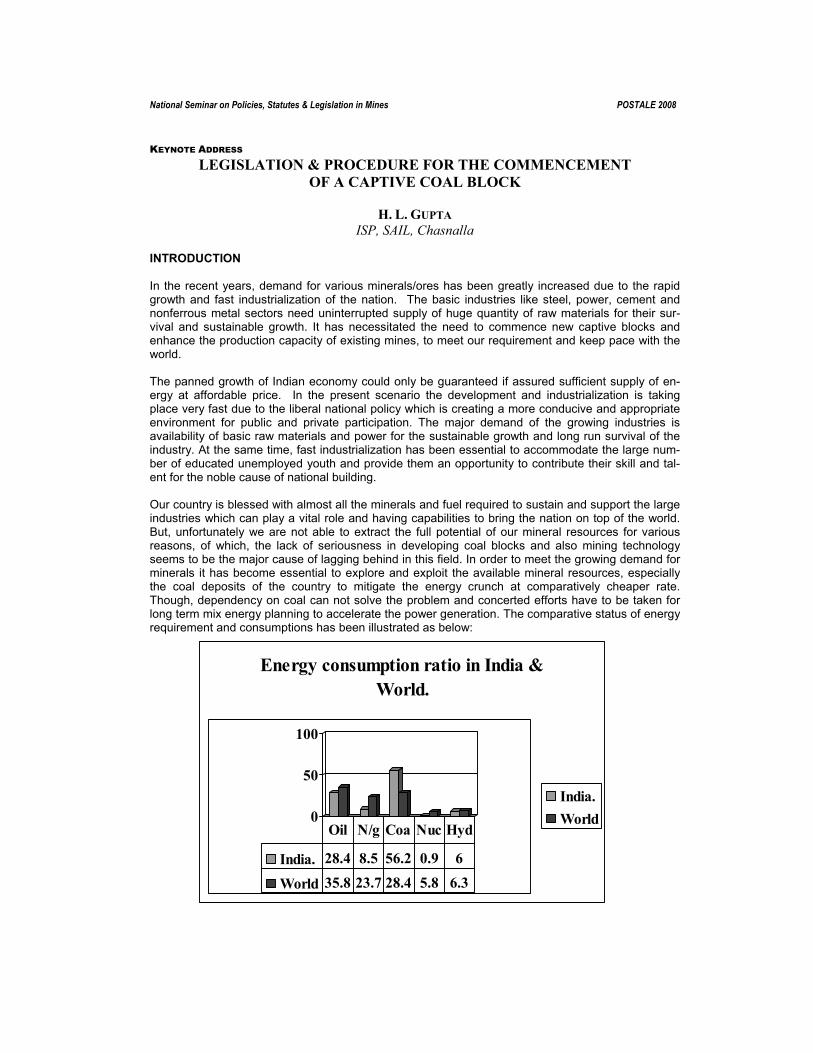
National Seminar on Policies, Statutes & Legislation in Mines POSTALE 2008
KEYNOTE ADDRESS LEGISLATION & PROCEDURE FOR THE COMMENCEMENT
OF A CAPTIVE COAL BLOCK
H. L. GUPTA ISP, SAIL, Chasnalla
INTRODUCTION In the recent years, demand for various minerals/ores has been greatly increased due to the rapid growth and fast industrialization of the nation. The basic industries like steel, power, cement and nonferrous metal sectors need uninterrupted supply of huge quantity of raw materials for their sur-vival and sustainable growth. It has necessitated the need to commence new captive blocks and enhance the production capacity of existing mines, to meet our requirement and keep pace with the world. The panned growth of Indian economy could only be guaranteed if assured sufficient supply of en-ergy at affordable price. In the present scenario the development and industrialization is taking place very fast due to the liberal national policy which is creating a more conducive and appropriate environment for public and private participation. The major demand of the growing industries is availability of basic raw materials and power for the sustainable growth and long run survival of the industry. At the same time, fast industrialization has been essential to accommodate the large num-ber of educated unemployed youth and provide them an opportunity to contribute their skill and tal-ent for the noble cause of national building. Our country is blessed with almost all the minerals and fuel required to sustain and support the large industries which can play a vital role and having capabilities to bring the nation on top of the world. But, unfortunately we are not able to extract the full potential of our mineral resources for various reasons, of which, the lack of seriousness in developing coal blocks and also mining technology seems to be the major cause of lagging behind in this field. In order to meet the growing demand for minerals it has become essential to explore and exploit the available mineral resources, especially the coal deposits of the country to mitigate the energy crunch at comparatively cheaper rate. Though, dependency on coal can not solve the problem and concerted efforts have to be taken for long term mix energy planning to accelerate the power generation. The comparative status of energy requirement and consumptions has been illustrated as below:
0
50
100
Energy consumption ratio in India & World.
India.World
India. 28.4 8.5 56.2 0.9 6
World 35.8 23.7 28.4 5.8 6.3
Oil N/g Coa Nuc Hyd

POSTALE 2008
30
Energy consumption ratio in India.
28%
9%56%
1%
6%
OilN/GasCoalNuclear/EHydro/E
In the present situation, the role of a geologist in mining industry is to provide correct and precise information about the mineral deposit their qualitative & quantitative assessment and economic fea-sibility. This helps to facilitate the mine planner to decide the suitable and appropriate method of min-ing to exploit the mineral at bare minimum cost. There has been realization and seriousness in the recent years to develop and extract the mineral potential to cater the growing need of steel, power and other industries. As a result the government of India has taken initiatives to allocate captive blocks of coal, Iron ore and other minerals, to the private and public sector companies to develop their own resources and reduce the dependency on import. Though the coal blocks have been iden-tified for allocation in the year 1993, but actual momentum gained after year 2003. Total 188 nos. of blocks allocated till the year 2007, out of which production started in only 14 blocks and production expected to start in 19 blocks by 2009, whereas other blocks are under different stages of develop-ment. The percentage-wise demonstration show by pie diagram as below:
Energy consumption ratio of World
36%
24%
28%
6%6%
OilN/GasCoalNuc/EHydro/E

POSTALE 2008
31
155, 83%
14, 7%
19, 10%
U/progressProd.StartedProd. Expected 08-09
Status of Coal Blocks (188 Nos) allocated till 2007. India is blessed by huge occurrence of coal deposits in different regions of the country and with re-gard to proved coal deposit it ranked third position in the world. The total reserves as estimated by GSI is around 255.20 Billion tones out of which 97.9 BT falls under prove category whereas 157.3BT still under indicated & inferred category, and this provides an immense scope of exploration work for maximizing reserves under prove category. The CIL and CMPDIL has already taken initiative by inviting global Expression of Interest (EOI) for undertaking massive exploration work, in order to con-vert more and more coal reserves under proved category. The category and depth-wise reserves have been illustrated as below:
Depth-wise distribution of coal reserves (source-GSI report)
61%
31%
8%
0-300m300-600m600-1200m
Coal reserves in Billion Tones.(255.20)
0
50
100
150
Category -wise coal reserves as on 01.01.2007
Proved 17 80.47 0.43 97.9Indicated 13 105.89 0.11 119Inferred 2 35.93 0.37 38.3
Coking Non- Lignite Total

POSTALE 2008
32
Due to the impetuous boom in the geological exploration & mining sector, demand for the experi-enced professionals and consultants have suddenly increased to plan, develop and commence a new mine for the optimum production of mineral for their respective industries. Since, there has been a series of legal provisions and statutory compliances of central and state government like DGMS, IBM, SPCB, MOEF, Coal Controller, DGM, DMO and Administrative Authorities involved for obtaining lease and number of clearances, it is essential and imperative for a professional to have complete knowledge and awareness of all the prerequisite provisions and procedures to plan and set a mile stone for effective time bound controlling and timely commencement of the project. In the recent years, many new thermal power plants are proposed to cater the need of growing elec-tricity demand in the country. Also due to the massive expansion programme of Steel plants, the requirement of both metallurgical and thermal coal will enhanced. Considering the requirement these industries a sincere and fast development of existing coal blocks is very much imperative. The coal production and demand status has been illustrated as below;
Coal production and demand status.
0100200300400500600700800
2002-3
2004-5
2006-7
ProductionDemand
Year - 2002-3 2003-4 2004-5 2005-6 2006-7 2011-12(Projected) Production - 341.23 361.06 386.95 405.00 431.5 680.00
Demand - 369.23 384.07 418.02 465.74 473.18 731.00 In India maximum coal production comes from open cast mining whereas underground coal produc-tion is less than 15 % of total production as a result Open cast reserves are depleting very fast, fur-ther open cast mining has become more difficult due to the problem of land acquisition and rehabili-tation of project affected persons. Under these conditions impetus has to be given to extract opti-mum reserve by comprehensive planning to the maximum depth by adopting both opencast and U/G method. The ratio of production comes from O/C and U/G method illustrated below

POSTALE 2008
33
The above articulated reasons, inspired the author to write this paper, using his 21 years diversified and vast experiences of being associated with number of projects of Coal, Iron Ore, Bauxite, Gold, Coal Bed Methane and many others during the tenure of various Government, Public sector and Corporate companies. The main objective of this paper is to provide comprehensive, consolidated and ready-made information pertaining to every aspects of executing a new mining project, which will be extremely helpful, time saving and cost effective for the companies to develop a captive mine in schedule time. Briefly and broadly the following steps are involved in the implementation of a captive mine: • Reconnaissance of the area, with specific aim to assess the lateral extent of deposit, existing
manmade and natural features, means of communication and transport etc. intend to apply for mining lease.
• Background and history of the block, related to previous exploration and mining activities has to be collected. Exploration report of total reserves their quality and suitability for end use.
• After the assessment of above aspects, the area can be scrutinized for obtaining lease under MCR-1960. Application for lease in a prescribed format (Form-1) submitted along with stipulated fee of Rs. 2500/- under sub rule (3) of rule 22, and desired documents like brief details of area, deposit, tentative reserve & quality, cadastral map showing the proposed lease boundary de-marcation, Certificate of registration of the company, list of technical personals, consent of the villagers,
• The scrutiny of competent consultant for the preparation of Detail Project Feasibility Report and Mine Plan along with mine closure plan should be identified, and simultaneously progress along with other activities.
• The TOR (Term of Reference) of concerned block along with Form-A is to be submitted to the Secretary, MOEF, New Delhi, for approval and further guidelines for preparation of Environ-mental Impact Assessment and Environmental Management Plan (EIA/EMP).
• Appropriate and authorized agency to be short listed for preparation of EIA/EMP of the mining block considering all the statutory requirement of State Pollution Control Board and MOEF.
• Consequent to the approval of mine plan by Ministry of coal or by IBM in case of metallic de-posit, process of conducting Public Hearing for approved capacity should be initiated.
• The application submitted to the Member Secretary, SPCB, for presentation and obtaining date for conducting P/H. This should be widely advertised in leading local news paper and also an-nounced in all the villages falling within 10 km. radius.
• The public hearing is conducted in the chairmanship of DC or his representative and under the technical supervision of Regional Officer, SPCB, other members who participate are senior citi-zens, Sarpanch of villages. In the process of P/H details of project deliberated and opinion of the project affected people (PAP) recorded by RO, and queries raised by villagers suitable reply given to them which is also duly recorded by RO. The video recording of whole proceedings is

POSTALE 2008
34
done and the CD along with questionnaire and report of RO pertaining to consent of people, sent to the Member Secretary, SPCB, for his comments and onward submission of report to the Sec-retary, MoEF. After obtaining the consent of villagers, the SPCB issues a No Objection Certifi-cate (NOC).
• The NOC along with approved mine plan and EIA/EMP, sent to the Secretary, MoEF, New Delhi for obtaining final environmental clearance in respect of the project.
• After the environmental clearance is obtained, the process of land acquisition as per the re-quirement for the purpose of mining and also for erection & establishment infrastructure, should be initiated with the land owner and revenue department. The process of tendering for different jobs may also be initiated to avoid delay in project schedule.
• The coal Controller Office is to be approached for grant of prior permission for mining. Simulta-neously DGMS and other statutory bodies should also be intimated regarding the opening of mine.
• The man-made structures like water pipe lines, High Tension transmission line, roads or any other such structure falling within the mining block and needs diversion or shifting, action should be initiated in advance to avoid delay. Authorities concerned to be consulted, for the appropriate solution.
• The engagement of suitable agency for developing and operating mines by adopting state of the art technology to extract optimum reserve.
• In case of re-location of population for mining purpose, Implementation of rehabilitation and re-settlement plan in line with the R&R policy of State Govt./ Govt. of India as applicable, has to be executed. The socio-economic survey has to be conducted to assess the various aspects of pro-ject affected people.

POSTALE 2008
35
FLOW CHART FOR ACHIEVING MILE STONE OF MINING ACTIVITIES.
DETAILED TOPOGRAPHICAL SURVEY.
DETAIL EXPLORATION OF THE BLOCK.
CHEMICAL ANALYSIS OF THE SAMPLES.
ESTIMATION OF RESERVES & GRADE.
PREPARATION OF DETAILED GEOLOGICAL REPORT.
PREPATION OF MINE PLAN BY RQP AND INITIATION OF PROCESS, FOR OBTAINING ENVIRONMENTAL CLEARANCE FROM STATE POLLUTION CONTROL BOARD AND MOEF.
APPLICATION FOR GRANT OF MINING LEASE TO BE SUBMITTED ALONG WITH PRESCRIBED FEE (RS.2500) AND RELATED DOCUMENTS LIKE CADASTRAL PLAN SHOWING LEASE BOUNDARY. PLOTWISE DETAILS OF REVENUE, FOREST AND GOVERNMENT LAND, CONSENT OF VILLAGERS, GEOLOGICAL PLAN WITH BRIEF DETAILS OF RESERVES & GRADE. LIST OF TECHNICAL PERSONS. NO DUES CERTIFICATE FROM INCOME TAX DEPTT7 MINING OFFICE.

POSTALE 2008
36
ROAD MAP FOR OBTAINING ENVIRONMENTAL CLEARANCE
SUBMISSION OF FORM-I ALONG WITH PRE-FEASIBILITY REPORT TO THE MOEF FOR OBTAINING DATE FOR TOR PRESENTATION.
MINE PLAN PREPARATION BY RQP AND SUBMISSION TO MINISTRY OF COAL , FOR OBTAINIG DATE FOR PRESENTATION.
TOR PRESENTATION FOR ITS APPROVAL FROM MOEF.
MINE PLAN PRESENTATION FOR APPROVAL FROM MOC.
PREPARATION OF EIA-EMP BY REGISTERED AGENCY, AS PER GUIDELINES OF APPROVED TOR.
REVISION OF MINE PLAN AS PER QUERRIES & SUGGESTIONS OF COMMITTEE MEMBER, MOC, AND SUBMISSION FOR FINAL APPROVAL.
APPROVED MINE PLAN. APPLICATION IN PRESCRIBED FORMAT FOR OBTAINING NOC U/S 25&26 OF WATER ACT AND U/S 21 OF AIR ACT 1981 ALONG WITH SPECIFIED FEE AND DESIRED DOCUMENTS LIKE PROJECT REPORT, COPY OF LEASE TRANSFER AND MOUZA PLAN SHOWING BLOCK BOUNDARY TO BE SUBMITTED. FOR OBTAINIG DATE FOR TECHNICAL PRESENTATION RELATED TO PUBLIC HEARING , AN APPLICATION ALONG WITH FEE (1.5 LACS) AND COPY OF APPROVED TOR & EIA-EMP TO BE SUBMITTED TO THE MEMBER SECRETARY, SPCB.
AFTER PRESENTATION, DATE FOR P/H OBTAINED AND WIDELY PROPAGATED IN PROJECT AFFECTED VILLAGES, NEWS PAPERS, AND LOCAL MEDIA.
ADEVERTISEMENT OF P/H NOTICE IN LOCAL NEWS BY SPCB.
P/H CONDUCTED UNDER CHAIRMANSHIP OF DC IN PRESENCE OF SPCB OFFICIALS AND VILLAGE REPRESENTATIVES.
CONSENTS AND SUGGESTIONS OF PUBLIC RECORDED BY RO AND RECORDING OF WHOLE PROCEEDINGS ALONG WITH JOINTLY SIGNED CONSENT RECORD SENT TO THE MOEF.
DATE ALLOCATED BY MOEF FOR FINAL PRESENTATION OF EIA-EMP.
AFTER SATISFYING THE QUERRIES AND SUBMISSION OF APPROVED MINE PLAN FINAL MOEF CLEARANCE IS GRANTED.
AFTER OBTAINING MOEF CLEARANCE THE PROCESS OF LAND ACQUISITION STARTED WITHIN LEASE BOUNDARY, FOR MINING AND ERRECTION OF SUPPORTIVE INFRASTRUCTURE.
APPLICATION FOR PRIOR PERMISSION TO OPEN A COAL MINE UNDER CLAUSE 9(2) OF COLLIERY CONTROL RULE 2000, IS TO BE SUBMITTED IN PRESCRIBED FORMAT TO THE COAL CONTROLLER ,MINISTRY OF COAL & MINES,
PRIOR APPROVAL OF COAL CONTROLLER OBTAINED.
STATUTORY COMPLIANCES OF DGMS ALSO INITIATED SIMULTANEOUSLY.
THE OTHER ACTIVITIES RELATED TO TENDERING AND OUTSOURCING SHOULD ALSO START SIDE BY SIDE .
CIVIL WORK AND INSTALLATION OF MAJORE EQUIPMENT, INSTALLATION OF TRANSFORMER AND POWER SUPPLY LINE FOR MINE LAID DOWN AS PER DPR , TO BE EXECUTED.
PRDUCTION COMMENCED AND GRADUALLY CAPACITY ENHANCE TO THE APPROVED PEAK RATED CAPACITY. RAW COAL SUPPLIED TO THE WASHERY AND CLEAN COAL FINALLY SUPPLIED TO THE STEEL PLANT/ THERMAL POWER FOR END USE.

POSTALE 2008
37
Application for Reconnaissance permit under MCR-1960. Applied in Form-A , along with plan in quadruplicate showing all details about area and fee @ Rs. 5/- per Sq Km and part thereof
Application for prospecting license under MCR-1960. Applied in Form-B, along with plan and topographical map in triplicate showing block boundary and other details of the area, and Fee rs. 50/- for first Sq Km and @ Rs.10/- for rest Sq Kms &part thereof.. Security deposit to be made @ Rs.2500/-Sq km and part thereof. Application for renewal of PL given in Form-E with Fee Rs. 50/ for 1st and then @ Rs.10/- Sq Km.
Application for Mining Lease MCR-1960 (Rule 22(1). Applied in Form-I, Fee Rs.2500/- under sub-rule (3) of rule 22, along with Geological plan, Survey plan and cadastral plan showing plot-wise details of private, Govt & forest land. Also village boundary and forest boundary should be shown on the plan.
Mining plan & Progressive Mine Clo-sure Plan under MCDR-1988 to be submitted to IBM (for Metal mines) along with processing fee of Rs. 1000/-per Sq km under rule 22BB of MCR-1960.
In case of Coal blocks, Mine Plan &PMCP submitted to Ministry of Coal,under MCDR-1988, for its approval.
Approved mine plan along with EIA-EMP & Public Hearing Report submit-ted to MoEF for obtaining final Envi-ronmental Clearance, under MoEF Ga-zette Notification No. 1533 dt. 14.09.2006
Approved mine plan along with EIA-EMP & Public Hearing Report submitted to MoEF for obtaining final Environmental Clearance, un-der MoEF Gazette Notification No. 1533 dt. 14.09.2006
Mine opening notice given to IBM, DGMS and also SPCB. Production started after executing statutory provi-sions of DGMS & other regulatory au-thorities.
Application for prior permission to open a coal mine from office of the Coal Controller under clause 9(2) of colliery control rule 2000. Pro-duction started after executing statutory provisions laid by DGMS.& other regulatory authori-i
FLOW CHART OF ACTIVITIES FOR OBTAINING MINING LEASE & ENVIRONMENTAL CLEARANCE FOR THE PROJECT.

POSTALE 2008
38
LEGISLATION FOLLOWED, DURING OPENING OF MINE FOR PRODUCTION. RETURNS, NOTICES AND RECORDS, (COAL MINES REGULATIONS-1957).
NOTICE OF OPENING IN PRESCRIBED FORM (FORM-I) ACCOMPANIED BY A PLAN SHOWING MINE BOUNDARIES AND DISTINCTIVE FEATURES, SHALL BE SUBMITTED TO THE CHIEF INSPECTOR & REGIONAL INSPECTOR.
AFTER OPENING OF MINES ACTUAL DATE OF OPENING AND MONTHLY RETURNS IN RESPECT OF PRECEDING MONTH IN FORM-II, SHALL BE SUBMITTED BY AGENT/OWNER OF MINES WHICH CONTAINS DETAILS OF RAISING,DESPATCH&STOCK(TABLE-A) MACHINERY(B), NUMBER OF MAN-DAYS (C), HOURS OF WORK & EARNING (D)
ANNUAL RETURNS SHOULD BE SUBMITTED BY THE AGENT/OWNER OF MINES IN RESPECT OF PRECEDING YEAR, IN FORM-III, WHICH CONTAINS DETAILS OF EMPLOYMENT (TABLE-A),TYPE&CAPACITY OF ELECTRICAL APPARATUS (B), TYPE&CAPACITY OF MACHINERY AND EQUIPMENT (C), EXPLOSIVES,SAFETY LAMPS AND MECHANICAL VENTILATORS (D), OUTPUT (in tones) (E), LEAVE WITH WAGES AND COMPENSATORY HOLIDAYS (F).
NOTICE OF ACCIDENT SBMITTED IN FORM-IV-A & IV-B GIVING DETAILS OF ACCIDENT, PLACE, TIME, NATURE OF ACCIDENT AND RESPONSIBILITY.ETC.
ANY COTRAVENTIONS DURING INSPECTION RECORDED IN FORM-VI.
NOTICE OF ABANDONMENT OR DISCONTINUANCE STATING THE REASON FOR SAME AND NUMBER OF PERSONS LIKELY TO BE AFFECTED THEREBY, SHALL BE SUBMITTED TO CHIEF INSPECTOR.

POSTALE 2008
39
Time Schedule for achieving the mile stone: Sl. No.
Event Time limit. (In months)
Activities executed to achieve goal within time limit.
1 Allocation of Captive Block.
Date of allo-cation is taken as ‘0’ date.
Proposal considered by the Screening Committee, MOC, on the basis of merit and priority.
2 Purchase of Geological Report.
1-2 In reference to allocation letter, the GR obtained from the concerned department by paying the Exploration cost of the block.
3 Bank Guaranty. 3. Bank Guaranty submitted to the Ministry of Mines. 4 Mining Lease Application. 3. Application along with project details and plans show-
ing proposed lease boundary, shall be submitted to District Mining Officer.
5 Mining plan submission. 6. Mine plan prepared by RQP, shall be submitted to MOC for approval.
6 Mining plan approval. 8. After presentation and necessary modification as sug-gested by Expert Committee, Mine plan is approved.
7 Environmental clearance application
12. Consent of PAP obtained by conducting Public Hear-ing, and all the documents of P/H proceedings along with copy of Approved mine plan and EIA-EMP submit-ted to Member Secretary, State Govt for their approval and onward submission to MOEF.
8 Forest clearance applica-tion in case of forest land available within lease hold area.
12. Application along with Lease plan and forest compart-ment plan submitted to the DFO for his approval and onward submission to CF for issuing Forest Clearance for said area.
9 Environmental clearance from MoEF.
18. After presentation before MOEF members and neces-sary modification if any suggested, Environmental clearance is granted.
10 Grant of Mining lease 24. After consistence pursuance and timely compliance of queries raised at various levels, lease is granted for 30 years initially and then renewed after expiry of lease period after review of project.
11 Land acquisition to begin. 19 Land acquisition can be executed under CBA Act or LA Act or transfer of ownership by registration process.
12 Land acquisition to be completed
30-36. Consistent efforts shall be made to mobilize people for obtaining their consent to give up land for mining pur-pose.
13 Application for opening mine.
30 – 40(OC) 48 – 52 (U/G)
Application for prior permission from coal controller shall be submitted and also opening notice to DGMS in the prescribed format to be submitted.
Permission to be granted for opening mine.
31-41 (OC) 49-53 (U/G)
Consistent pursuance and compliance of queries.
14 Production to be started. 36-42 (OC) 48-54 (U/G)
All tendering procedures executed for outsourcing job, installation of plant & machinery, power supply and mine development work for commencement of produc-tion.
15 Reaching the peak rated capacity
60- 66 (OC) 72- 78 (U/G)
Regular maintenance and monitoring of progress.
* The schedule time period has been projected considering the normal time required for completion of job, however this may reduce or enhance depending upon the efficiency and professional skill of the executer.
While executing a new project, the various ladders shown in the flow chart provides a guideline to move forward in achieving the goal. But each step involves a number of comprehensive stages and

POSTALE 2008
40
unless they are identified completely, it shall be difficult for executer to decide the course of action on priority. Therefore, efforts have been made to deal with each event in detail in the following chapters: • Reconnaissance and brief history of the block. • Detail exploration & estimation of reserves. • Application for grant of lease under MCR-1960. • Project Feasibility Report on the basis of exploration report. • TOR, proposal of project for MOEF approval. • Mining plan preparation as per approved TOR. • EIA & EMP preparation for the approved capacity of the mine as per TOR. • Land acquisition as per LA Act -1894 or CBA (Acquisition & Development) Act-1957. • Rehabilitation & Resettlement of Project Affected Families (PAF) as per the notification of Govt.
of India / State Govt. • Tender process for the outsourcing jobs related to mining and allied activities. • Installation of plant & machinery, arrangement of power supply and distribution system. • Application for obtaining prior permission from Coal Controller and compliance of DGMS provi-
sions for opening/commencement of mine. • Statutory compliances of DGMS, DMO, SPCB, Coal Controller and other regulatory authorities. • Monitoring of production by making phase-wise, month-wise, sector-wise plan. • Transport of ROM coal from mine pit to the washery and arrangement of Rake (Wagons-58)
from Railways for transport of clean coal to the plant for captive use. • Coal washing and quality monitoring for end use. • Reclamation of mined out land and execution of EMP (Environmental Management Plan). • Implementation of CSR policies for improving socio-economic status of PAP. • Regular monitoring of Air, Water, Soil quality & Noise data and compliance with SPCB. • Compliance with Coal controller office and Mining office for sand stowing &protective work and
payment of royalty respectively. • Massive plantation and development of social forestry for clean environment and benefit of the
local inhabitants. LAND ACQUISITION In general the transfer of land by buying and selling is executed through registered deed under the Registration Act. But, in this type of land transaction, both the parties have mutual interest to execute the deed. When land is to be acquired for public purposes, development projects, erecting infrastruc-ture facilities, mining activities for the extraction of different minerals to meet the requirement of our industries in the interest of nation, there may be cases where people may not willingly give up their land. Under these conditions, the need was felt for enactment of Land Acquisition Act -1894 and Coal Bearing Areas (Acquisition & Development) Act-1957 for compulsorily acquisition of land for public and developmental purposes. Land Acquisition Act -1894: The salient features of this Act are noted as below • Only tenancy land can be acquired under this Act. • Only surface right can be acquired, hence, mining lease is required for undertaking any mining
activity. • Acquisition of land is done by State Govt. representatives and land compensation also deter-
mined and paid by the District Land Acquisition Officer after receiving estimated amount from company.
• Even after acquisition of land if the land is not required /utilized , this can be de-notified or trans-ferred to the State Government.
Coal Bearing Areas (Acquisition & Development) Act, 1957: The salient features of this Act is noted as below:

POSTALE 2008
41
• Under this Act only coal bearing area can be acquired for mining and allied purposes. All rights for mining both by O/C & U/G method can be acquired.
• Since, all rights for mining activities is acquired under CBA Act, there is no need of grant of lease from State Government.
• Acquisition of land done by the Central Government, but the compensation of land is determined and paid by the company.
• There is no provision for de-nomination of land once acquired. REHABILITATION & RESETTLEMENT PLAN FOR PROJECT AFFECTED FAMILIES: • Social Impact Assessment (SIA) is mandatory where the involuntary displacement of large num-
ber of families is involved. • Tribal development plan is must where the involuntary displacement of sizable number of tribal
is involved. • The SIA report shall be examined by an independent multidisciplinary expert group. • There is a provision to appoint a commissioner/Administrator by the State Govt. to execute R&R
and allot land and sanction the benefit to affected families in consultation with Gramsabha and Investor, as per the Rehabilitation & Resettlement plan as notified by Government of India.
WASHERY FOR THE BENEFICIATION OF RAW COAL The quality of coal is determined by the Ash% and coking properties on the basis of which, the utility of coal in thermal power plant, steel industry and other sectors are decided. In the steel industry cok-ing coal with low ash content is required, but mostly the coking coal reserves confined to the Jharia coal field having comparatively high ash content as compare to Australian coking coal which con-tains fairly low ash varying from 6 to 8%, in order to meet the steel plant specifications the indige-nous coking coal is invariably beneficiated to reduce the ash content to the level of around 18%, which is further suitably blended with low ash Australian coal to obtain the desired coke quality. Similarly huge quantity of non-coking coal which contains high ash content along with contamination in the form of Shale is burnt for electricity generation in thermal power plants. The use of unwashed coal produces huge quantity of fly ash which not only pollutes air, water and land but also create a serious problem of dumping space. This problem can be reduced by beneficiation of coal and ensuring consistent ash content, which will not only improve the performance of plant but also reduce pollution load and fright charge and load on the road transport. CONCLUSION This paper can attribute to the acute need of awareness to various entrepreneurs who have been allocated coal blocks for mine development. Mining of coal is ever remains a challenge because of its nature of occurrence and intricate geo-mining conditions. Assessment of geological reserve, qual-ity and grade, proper planning, cost feasibility study for the commercial exploitation of coal seams, maintaining standard safety norms, compliances with statutory provisions, socio-economic manage-ment, implementation of rehabilitation of displaced people and finally developing an eco-friendly en-vironment are the major task which has to be managed by an efficient professionals. This paper pro-vides concise, consolidated and handy information which are extremely helpful for all professional and entrepreneurs who have venture in mining sector. ACKNOWLEDGEMENT The author is thankful to Shri U. P. Singh, Executive Director (Collieries) for his kind permission to publish this paper and deeply indebted to Shri P. Prasad, General Manager –I/C (Collieries) for his valuable guidance and important suggestions in inscription of this paper. The views expressed in this paper are those of the author and not necessarily of the organization.

POSTALE 2008
42
The figures & data taken from News papers, Mining & Geology Journals, Coal Insight and Notifica-tions & Guidelines issued time to time. Whereas, the procedures based on the general guidelines and working experiences while practically executing the job.
FLOW CHART FOR BENEFICIATION OF RAW COAL.
RAW COAL (1.0 tone) WITH ASH CONTENT 35-40%
RAW COAL AFTER MANUAL DESHALING (0.8 tone) WITH 2-3% REDUCTION IN ASH CONTENT.
RAW COAL SENT TO CRUSHING PLANT TO OBTAIN DESIRED SIZE FOR BENEFICIATION. (-) 75mm and (-) 20mm size separated by screening.
AFTER BENEFICIATION FOUR PRODUCTS ARE GENERATED AND GENERALISED QUANTITY IN TERMS OF PERCENTAGE ARE CLEAN COAL ( 50%) MIDDLING (20%) SLURRY (10%) & REJECT (20%)
FINALLY IF WE ASSESS THE REALISATION VALUE OF ALL PRODUCTS, IT COMES MORE THAN THE MARKET PRICE OF RAW COAL. CERTAINLY THERE IS HIGHER PROFIT, BETTER PERFORMANCE, LESS POLLUTION LOAD, REDUCED LOAD ON TRANPORT AND ABOVE ALL COMPARATIVELY LESS LAND IS REQUIRED FOR DUMPING OF FLY ASH.
ENFORCEMENT & ENCOURAGEMENT SHOULD BE THERE TO PROMOTE USE OF WASHED COAL IN THERMAL POWER PLANTS.

National Seminar on Policies, Statutes & Legislation in Mines POSTALE 2008
POLICIES, LEGISLATIONS AND STATUTES FOR OPENCAST MINES OF NEYVELI LIGNITE CORPORATION LTD, NEYVELI, TAMIL NADU.
A.R. ANSARI
N.L.C. Ltd, Neyveli. INTRODUCTION Neyveli Lignite Corporation Limited (NLC), a ‘Mini Ratna’ Government of India Enterprise functioning under the aegis of Ministry of Coal became a reality in the year 1956. It has now become a prime energy source to the Southern States. Its core business is Lignite mining and Thermal Power gen-eration. The main constituent Units of the Company are three opencast lignite Mines linked to three Thermal Power Plants with a total mining capacity of 24 MTPA and Power Generation of 2490 MW. NLC has emerged as an integrated Project consisting of Mine-I and II each with capacity of 10.5 MTPA and Mine-IA with a capacity of 3.0 MTPA; Thermal Power Station-I and II with capacity of 600 MW and 1470 MW respectively and Thermal Power Station-I Expansion with capacity of 420 MW (2 x 210 MW). NLC is on continual improvement in its performance and is making profits continuously from 1976-1977 onwards. NLC has also taken up several Expansion / New Projects for its sustainable growth in the years to come.
Projects under construction Name of the Project Capacity Investment (Rs.in Crores)
Mine-II Expn. 10.5 to 15.0 MTPA 2161.28 Thermal Power Station-II Expn. 2 x 250 MW 2030.78
Rajasthan Mine 2.1 MTPA 254.07 Rajasthan Power Project 2 x 125 MW 1114.18
Coal based Thermal Power Plant at Tu-ticorin Tamil Nadu 1000 MW 4904.54
Necessity For A Separate Legislation , Policies & Acts For Lignite Mining Industry Coal is the prime source of fuel and is contributing 60 to 70 % to the energy sector. Prior to the na-tionalization, coal was only source in the country for the energy generation. The southern and west-ern parts of the country entirely depend up on the energy generated from the remaining parts of the country. Detailed exploration strategy adopted in the south confirmed the another source of fuel - “ Lignite “ availability in late 1940s. Since then on, lignite mining was planned and NLC as Lignite min-ing cum power generation company blossomed. The policies & Legislations of the coal sector was adopted as such for the lignite Mining sector own-ing to the fact that resources of lignite (38 Billion Tones) constitute only 15% of the coal resource (248 billion Tones) in the country .The lignite mining is besieged with high pressure aquifer beneath the Lignite bed and vast open areas are required to keep the mining operation on for the safe mining condition. Under such above unique geo- mining conditions it would be appropriate to have separate Acts & Legislations framed for the lignite mining Industry. In this context, NLC would to present the existing system of Developing, Working & Implementing the statutory requirements on Government Policies and issues on Safety & Work Environment, Min-eral Conservation, Mining Lease, Environment & Ecology, Socio-Economics, Mine Closure, Energy conservation & Human Resource Development fields.

POSTALE 2008
44
GOVERNMENT POLICIES Lignite Exploration • Lignite Exploration in India is being done as per the Action Plan & direction of Sub-Committee on
Coal & Lignite , GOI • Target area for Lignite exploration will be identified by the Sub-Committee on Coal & Lignite. • NLC is the Nodal agency in monitoring the country’s Exploration in Lignite. • M/s MECL is executing the above work for NLC • Sub Committee on Coal & Lignite reviews’ the progress NLC’ S Role On Lignite Block Development • Based on the results of Exploration, NLC identifies potential lignite Blocks for development
through Private entrepreneurs. • MoC has identified NLC as a nodal agency for lignite Data Base Creation. • NLC is developing Integrated Lignite Information System ( ILRIS ) A Project funded by MoC for Rs. 7.5 Crores A First of its in the Country • NLC assists MoC for scrutinizing the Lignite mining proposals by other agencies. • NLC is member of Screening Committee for block development, to allot the Captive Block to
private agencies • NLC assists MoC in inviting bids for lignite block development and also scrutinize the Mine Plan proposals. • NLC is the nodal agency in maintaining & updating country’s lignite production data and explora-
tion data. • In India, about 75 % of Lignite Production is being done in India by NLC . Factors Affecting Financial Heath Of Lignite Companies. • Surplus Man Power • Low capacity utilization • Untimely revision of Lignite Prices • Huge outstanding Dues Reforms In Lignite Sector • Reforms in lignite sector followed by in Power Sector in eight Plan (1992-97) • Allowed private sector in captive Lignite Mining • Import duties reduced considerably Issues Affecting The Growth Of Lignite Sector • Non Participation of Indian Private Sector and foreign equity in coal/lignite mining. • Non establishment of a regulatory for controlling the coal /lignite mining in the private sector. • Need to consider the amendment of the Mines and Minerals (Regulation and Development ) Act
1957. • Need to frame policy measures for quick land acquisition. • Need to consider the amendment of the Contract labour (regulation and abolition) Act of 1970 . • Need for notification for coal / lignite section as infrastructure industry. SAFETY & WORK ENVIRONMENT First Mining Company in India under Ministry of coal to get three ISO certification for Quality Control , Environment Management & Occupational Health and safety.

POSTALE 2008
45
ISO 9001 : 2000 - Quality Control ISO 14001:2004 - Environment Management . OHSAS 18001:1999- Occupational Health and safety
Following improvements were initiated in Health care facilities • Full fledged causality Department with all facilities • Preventive Medical examination for Employees • Separate lab for Out patients • Additional new Renal care unit to ensure dialysis. • Diabetic care with MV Hospital /Chennai • Screening for cancer patients • Recruitment of Specialized Doctors. • Telemedicine Facilities • Introduction of Integrated Hospital Management System . • Setting up Trauma Care Unit • Introduction of Integrated Counseling & Testing Centre for HIV Following action has been initiated to minimize the causes due to human failure • By creating awareness among workmen/employees by imparting regular on the job training at
NLC GVTC /training centre • Appointment and supervision by duly certified competent persons are undertaken to create an
ideal and safe working environment. • Following best practices/standards • Continual improvement on safety awareness in mines through • Resources allocation • Monitoring of safety standards • Disaster safety management plan Safety measures adopted in mines I) Developments in Conveyor, Tail end cleaning • Long hand shovels are introduced instead of short hand shovels. • Extra pull cord switches are provided at Tail end area. • Locking systems are arranged at LCS panel to lock MCB switches while taking maintenance /
cleaning work. • In order to avoid manual cleaning at Tail End along the conveyor, Back Hoe is converted with
special attachment for conveyor cleaning. Now men need not to be exposed to the danger of working in the vicinity of running conveyor – for this is taken care of by the modified back hoe with attachment.
• Electronic Guarding System: Electronic Guarding system is introduced to stop the conveyor im-mediately if any one goes close proximity to the running conveyor as well as if tail end side got chocked due to spillage of soil.
II) Conventional Mining Equipments Modification Works in Dozer Hood Design: • Operators are provided with NO-NAP alert drowsy devices. • The role of a spotter is eliminated, since certain accidents were caused due to running over the
spotter by the dumper. • Dumpers and Dozers are provided rear view mirrors on both sides. • In order to reduce fatigue to the operator, the cabin is proposed to be air conditioned shortly .

POSTALE 2008
46
III) Specialized Mining Equipments In Neyveli Lignite mines, the Bucket Wheel Excavators play a major role in removal of overburden and lignite. These are giant machines engage about 100 to 150 persons belonging to different engi-neering disciplines who work on it to keep it in running condition. The above machineries fall under the category of specialized mining equipments. Certain safety steps taken at mines with regard to Sme Introduction of PLC Programmable Logic Controller (PLC) is an innovative measure introducing in giant excavators de-ployed for excavating the overburden and lignite seams. These measures prevents • Unauthorized persons from operating the excavator. • It totally eliminates wiring and contactors. This enables to prevent theft of the above materials. • It also eliminates the risk of flashover. • Any interference due to malfunctioning is also eliminated. • In remote and hazardous areas, which cannot be easily approachable by men, the PLC enables
works to be carried out there by means of remote operation from the operator cabin itself. Communication Network Since Mines comprises of very large area spread over 25 sq. kms for each of the mines and is de-ploying various machines scattered over long area, effective communication among personnel to keep in constant touch is mandatory. The entire NLC complex has been interlinked with optical link for integration of Data and Voice communication. Mines have been equipped with radio trunking wireless communication facility by which emergency messages can be passed directly to control overriding all other normal communication. In addition to wireless, telephone communications have been provided in GWC / SWC and other remote locations. In order to overcome the incidents of accidents that seem to occur due to negligence in mines vari-ous steps are taken such as • Psychology test: Counseling of workmen through qualified psychiatrists. • Breath analyzer tests: Excellent welfare measures are implemented such as good housing, good schooling, providing scholarships to the wards to keep an employee happy and contented. MINERALCONSERVATION In Neyveli Lignite Mines, Lignite is extracted with continuous mining System to facilitate 95% of lig-nite recovery compared to 85% in open cost mine with conventional technology. As a part of mineral conservation, priority should be given to plan & exploit higher stripping ration inferior quality mineral deposits just as being attempted in the Iron industry .More thrust may be given to develop Coal Bed methane Technology which will help in extracting the methane gas and leave the mineral resource as such for future exploitation. The under mentioned methods are being followed to exploit the lignite • Selection of Mining Area is in such a way that the Initial Mine Cut commenced on the favorable
area with minimum OB Lignite Ratio based on the Exploratory Bore well Details. • Check Bore Well Drilling are being established for tracing the multiple seam of lignite which is
not encountered during the initial exploration.

POSTALE 2008
47
• The Specialized Mining Equipment engaged in Lignite Mining , are modified in order to excavate the lignite in the power full artesian ground water condition
• Bottom Block of lignite immediately above the powerful aquifers exploited by bucket reversing & Backward movement.
• In order to tackle power full aquifer pressure below the lignite seam , bore well with 1000 GPM capacity are being drilled in advancing side leaving a lignite bund of width 10m.
• The lignite from this bund is being mined out by CME after exploitation of lignite by SMEs
MINING LEASE The Governor of Tamil Nadu sanctioned the grant of second renewal of Mining lease in favour of M/s Neyveli Lignite Corporation Limited to mine lignite ,ball clay ,fire clay, china clay and silica sand over an extend of 259 sq. kms. for a period of 20 years with effect from 06-12-1996 subject to the follow-ing conditions. • Necessary transport permits and dispatch slips are obtained for the minerals granted under min-
eral lease by Neyveli Lignite Corporation Limited from the concerned authorities. Silica sand should be separately mined by suitable mining methods and stocked and removed for disposal.
• Strict observation of the provision of Minerals Act- particularly safety distance pertaining to per-manent structures in railway line , high ways etc.
• An under taken to be obtained from Neyveli Lignite Corporation Limited to preserve the ecology .No area in the lease hold is sold or let out or transferred with out prior consent of the state gov-ernment.
Royalty to be paid Lignite : Two rupees and fifty paise per tonne and subsequently
revised to Rs. 64/ tonne Fire Clay : Rupees seventeen per tonne Ball Clay , China Clay Crude : Rupees eighteen per tonne Processed (including washed) : Rupees Sixty eight per tonne. Dead Rent First year of lease : Nil Second to fifth year of the lease : Rs.120/- per hectare per annum. Fifth year to tenth of the lease : Rs.200/- per hectare per annum. Eleventh year of the lease and onwards : Rs.300/- per hectare per annum. Revised Royalty from Aug. 2007 onwards o be paid Lignite : Rs. 64.00 per tonne tonne. Revised Surface Rent Rs. 51. 10 per Hectare Mining Lease Tax Rs. 62.00 Lakhs as Stamp duty Water Cess for Seepage water pumped out : Rs. 0.30/ Kilolitre Royalty, Surface Rent & Dead rents to be paid by Mining Company to the State Government , are being frequently revised . The different types of rents , taxes & Cess could be streamlined and stan-dardized under single head. The mining company is required to comply with the statutory payments to the state government , creating infrastructure mine closure fund and simultaneously spending for works such as reclama-tion, Rehabilitation & Peripheral development activities. The above factors are having direct influ-

POSTALE 2008
48
ence on the ultimate cost of mining . In this context , it is suggested that the fund collected may be used for the improvement works in local areas by State Government. Coal industry is operating under two different mining methodologies viz., Open cast and Under-ground. Due to this land acquisition problem in coal sector is not posing direct impact as compared to Lignite Sector where the mining is only through Open Cast method. Environment & Ecology NLC has been recognised by several awards in the field of eco-friendly management. • Indira Priyadarshini Vrikshmitra Award from Government of India – 1986. • FICCI Award for Environment Preservation and pollution Control – 1988. • K.P. Goenka memorial award for Environmental Care – 1988. • Fly Ash Utilization Award by Council of Power Utility – 1999. • Indo-German Green Tech Environmental Excellence Award 2000-01. • Business World FICCI – SEDF Award – 2006. • SCOPE Meritorious Award for Environmental Excellence and Sustainable Development for
2005-06. • Golden Peacock – Eco Innovation Award-2008. Land Reclamation and Afforestation Land degradation is one of the major adverse impacts of open cast mining and any effort to control this adverse impact would be incomplete without appropriate land reclamation strategy In land reclamation the following methodology is being followed • Planned overburden placement including backfill and regrading of the mined out area to the gen-
tlest topography consistent with other adjacent unmined area. • Establishment of good drainage system to check erosion. • Resorting to the use of biological reclamation techniques involving application of bio-fertiliser,
Humic acid, Organic matter and bring up of leguminous crops. • Careful selection of plant species, plantation methods and post care activities like irrigation, ap-
plying fertilizer etc. About 8,56,463 nos. of various types trees planted in & around Mine-II aprt fro m the slope stablisa-tion works carried out in external dumps . The various Research activities which are conducted in Mine spoil are given below • In house S&T projects .Bio Fertilizers reclamation of Mine spoil (CARD and Afforestation divi-
sion). • Rising of different kind of trees in mine-II area of 5 acres under VAM of (S&T) project • Fly ash utilization in agriculture (CFRI & NLC). • Indo-US project – For water harvesting. Air Pollution Remedial measures adopted in mines • The excavating face & dumping side of the mine is wetted constantly with spraying of water. • The transfer points/ hopper at the conveyor are provided with hoods/covers and the same are
adjusted from time to time. • The belt cleaning devices and rubber wiper are checked up daily during the maintenance time
and adjusted/replaced wherever necessary. • Water lorries, water dumpers, sprinklers are deployed for wetting of haul roads. On average six
water lorries and one water dumper are deployed daily. • Workmen are provided with respirators, goggles and dust masks. • Dense tree belts are created at the surface of the mine. • Trees are planted on both sides of the roads to arrest dust.

POSTALE 2008
49
• Readings of the dust samples are collected and analyzed once in 6 months i.e., in March and September to ensure that the dust concentration limit is contained within the allowable limits.
• All the conveyors(both lignite carrying & over burden carrying) have been provided with spray line to curtail dust.
Air Ambient Monitoring Eight hours Air Quality monitoring are carried out Core Zone in three Stations in in Mines-2 for RPM,SPM, NOX & SO2 . Continuous Air Quality monitoring are carried out Buffer Zone in five Sta-tions in and around Neyveli for SPM, NOX & SO2 . Test results shows they are with in limits pre-scribed by TNPCBd. Water Pollution Control & Water Management Control measures for surface water pollution • Retaining walls have been provided to prevent wash off from dumps and /or freshly excavated
areas. • Masonry chutes have been put up to guide the flow of water along the dump slopes. • Stabilization of dump slops by planting of appropriate plant species. • Providing baffles in the channel/drains carrying the storm to arrest the suspended solids, if any
present in the water. • Regular monitoring of mine water in having them tested/analyzed in the approved laboratories
every month. Measures to prevent ground water depletion • The area of draw down cone will be minimized by establishing ground water pumping wells
(GWC) as nearer to the lignite cut face as possible. • To enhance the ground water recharge potential to the Neyveli aquifer system, R & D study on
artificial recharge has been taken up in the deep water table zone ( recharge area for Neyveli aquifer system ) under Coal S&T grant.
• Impounding of surface run-off water, conservation of water. recycling of water etc. as apart of integrated ground water management.
• Regular monitoring of ground water samples in approved laboratories Regional Ground Water Monitoring A Separate Cell created in 1988(Regional Geology Dn.) 1. Dugwells monitored - 105 Nos 2. Tube wells (Confined Aquifer) - 80 Nos • These Wells are periodical monitored by N.L.C regularly including water quality. • In addition ground water data from State ground water departments, Central ground water de-
partments are also collected. • Data collection for water balance studies
Rain fall data collections - 14 Stations Meteorological Stations - 02 Stations
Noise And Vibration Control The noise and vibration are generally caused by • the mining machinery and other auxiliary/supporting equipments, • blasting operations, • movements of transport vehicles etc. Remedial measures • The moving /rotatory parts of the machineries are periodically checked and lubricated wherever
found necessary.

POSTALE 2008
50
• The noise created by the machineries are muffed with silencers to modulate the noise to toler-able level.
• Providing thick tree belt around the periphery of mine to screen the noise. • Providing workmen with ear muffs/ear plugs. • Reducing the exposure time of workmen to higher noise- level working area. • In the case of blasting, the effect of the shock/vibration is controlled at the mine surface level
itself by restoring to the use of milli second delay action detonators and milli second detonating relays.
Suggestion regarding Height of External Dumps The Environmental Clearance for Mines-II Expansion Project (10.5 MTPA to 15.00 MTPA) was ac-corded by MOE & F on 24-12-2002 with 20 specific Conditions and 17 General Conditions. Vide Special Condition No.2a ,” OB should be stacked scientifically at earmarked dump site(s). The total height of the external dump(s) should not exceed 65 m in two or three stages. Overall slope of the dump should not exceed 28o. Concurrent back filling and rehabilitation should start from the 5th year of operation. Monitoring and management of and Forests on yearly basis. At present the height of external dump of Mines-2 is 65m Owning to non availability of virgin land available for dumping , external dump height needs to be increased to 130 m with the over slope of 28o
M/s CMRI / Dhanbad. Indicated through its model study that the external dumps can be developed with a dump height of 130.00 m from Ground level . If the height is to be restricted as per the Special Condition 2a, NLC has to go in for acquisition of additional virgin land for dumping which in turn will cause additional land degradation . More over at present the space earmarked for the external dumping is getting exhausted and there is no available space for further dumping . Considering the various difficulties expressed above, it was requested for an early amendment to the earlier condition of the dump height as stipulated by MO E & F Constantly perceiving with MOE & F in this regard. SOCIO ECONOMICS NLC being a leading Public Sector & Mini-Ratna company , is functioning with social corporate re-sponsibility in implementing socio economic schemes. NLC has been recognized with SCOPE Award 2004-05 in the field of Corporate Social responsibility . Socio-Economic development • Production of desired products and rendering of quality services with minimum impact on the
environment, including the human environment (during the economic life) • Resettlement and Rehabilitation of the affected • Peripheral Development (regular extra-business contributions to the society) Benefits extended to PAF ( Project Affected Families) • Resettlement plot/house for the acquisition of house. • One time financial assistance for displacement with cattle for shed construction. • Shifting allowance to the displaced family. • One time financial assistance to the affected artisans/small trader or self employed for work
shed/shop construction. • Rehabilitation grant (750 days * maw (minimum agriculture wages)) in lieu of employment for acquisi-
tion of lands.

POSTALE 2008
51
• Subsistence allowance (300 days maw) to displaced families. • Life annuity to vulnerable persons not otherwise covered as part of a family. • Continuance of other support measures already in vogue like exgratia towards value of struc-
ture(s) on government lands, special iti apprenticeship training, self employment training, pap contractor registration, etc.
Schemes in operation for the benefit of the PAFs. • Special Training for PAF members under Medical Lab • Technician Training Scheme • Training for self-employment in co-ordination with Gandhigram Rural Institute • Several contracts are awarded to PAP Societies on concession. • Market Guaranteed Income Generating Scheme of cleaning material production & supply Peripheral Development scheme (PDS) • Allocating funds in the annual budget for PDS works and infrastructure development works such
as drinking water, schools, roads . • Present allocation of funds for NLC-PDS is Rs.200 lakhs/Annum. • Peripheral Development Committee (PDC) constituted with the Cuddalore District Collector as
the Chairman to identifying the peripheral development works Actvities: • Sinking of new bore wells • Cleaning and redeveloping of existing wells • Repairing and reconditioning of pumps • Construction of New school buildings • Health care camps covering maternity, childcare, immunization, cardiology, orthopedics, eye
care etc. • Out patients from the peripheral villages are treated in the NLC General Hospital. • Desilting of Lakes , Ponds , Tanks & Canals • Construction of Roads, foot-bridges, causeways etc Particulars of PDS works carried out
• Bore wells : 45 Nos. • Water tanks : 7 Nos. • Roads : 48 Nos. • Bridges/culverts/causeways : 5 Nos. • Eri (tank), de-silting, strengthening etc : 3 Nos. • School, library, toilet etc. : 9 Nos. • Street lighting : 1 Nos. • Miscellaneous like pavement laying, repairs to public building, etc. : 14 Nos. MINE CLOSURE Specific Mining conditions at Neyveli • Lignite is being mined out by open cast method deploying Continuous Mining Technology de-
ploying BWE, Spreaders and conveyor systems where excavation and backfilling is a continuous process which will culminate in a scientific mine closure process resulting in large working area compared with any other mining methods.
• The lignite is being mined by tackling the ground water at a very high pressure caused by the existing confined aquifers.
• Hence for the safety of the mine, the mine opening to be maintained at the de-coaled / de-lignited area, has to be at least 250 m width for the entire mine length, leading to a larger void at any given time of mine operation.

POSTALE 2008
52
• As mine is in monsoonic and Cyclone prone area, large sump has to be maintained to collect water from vast catchment area of the mine.
• So it is essentially necessary to re-handle external dump material to retrieve back the mined out area and to reduce the final void area and depth..
• The lignite is mined out at Stripping ratios as high as 1:10 and the average stripping ratio for all the mines at Neyveli is 1:6 and at Rajasthan it is 1:5, which is comparatively on the higher side when compared to other Coal mines. The new mine project at Bithok, Rajasthan is having a stripping ratio of 1:14.33.
• The Lignite formation at NLC mines are generally in plains. The outside dump volume on an av-erage is around 30% of the total OB volume. Hence there is corresponding increase in the final void to be re-filled.
• Also, the Strata conditions at NLC Mines are soft. This require more inputs for Landscaping, Grading of high-wall and dumps etc.
• The restriction on dump height upto 65 m also increases the area requirement for external dumping.
• In some places, the natural drains have to be diverted, which results in additional cost. Mine closure fund In order to ensure scientific methodology of Mine closure , a “Corpus Fund” should be generated by owner/operator of the mines as soon as the mining activity starts and supplemented during exten-sion of mining operation. • Fund should take into account the inflation and discounting factors. • As per the guidelines of MOC, the tentative Mine Closure Cost for the Mines of NLC Ltd has
been worked out and furnished. In NLC the Mine Closure cost estimates have been earmarked as detailed below: (cost/tonne) (1) For Mine - I = Rs. 37.86 (2) For Mine - IA = Rs. 17.44 (3) For Mine - II = Rs. 46.43 (4) For BLMP = Rs. 19.64. Even though the fund is earmarked for mine closure works by Neyveli lignite Mines , the actual re-quirement would be less , as the mining & refilling and developing the afforestation in the refilled area are concurrent works carried out alone with mining process. . ENERGY CONSERVATION NLC has given prime thrust in energy conservation in the open cast mining operation .The following conservation measures have been implemented in the Mine Expansion Equippment first in South East Asia:- • Medium voltage (690V) motors with Variable Voltage Variable Frequency (VVVF) control drives
are incorporated in the Mines-II Expansion machines & conveyors • Programmable Logic Controller (PLC) control in the Rotor Resistance circuits of Slipring drives
are being implemented in phases in various SMEs and Conveyors. Advantages of VVIF & PLC Control:
• Power factor of motors increased from 80% to 95% . • Speed of Conveyor Belt will get automatically adjusted to the load • Life of Conveyor Belt get enhanced • Frequent tripping of system avoided • Flexibility in operation. • Remote monitoring & Quick fault finding . • Machinery down time reduced.

POSTALE 2008
53
M/s MECON was engaged for the consultancy Service in Energy conservation of Mines-2.The rec-ommendations was being implemented by Various divisions of Mines-2 HUMAN RESOURCE DEVELOPMENT The Company gives high priority towards training of executives, supervisors and workers. Apart from utilising the training facilities available in the Training Complex of the Company, the employees are also deputed to other training centres within India. Training facilities provided by the equipment manufacturers within the country/abroad are also utilised. The number of employees in various categories behind the success of the company are
Executives :3,642 Non-executives :6,743 Labour :8,745 Total :19,130
Initiatives and activities undertaken to develop a culture of high performing organization Training for Organisational Effectiveness • Achieving organizational excellence through continuous development of its human resources
and accord priority for training and development. • Employees are given in house training, on job techniques, advanced technology, human rela-
tions, self-development, etc. • Annually, around 40% of the workforce is provided with Training opportunities Fostering Employee - Customer Relations through Training Staff of Telecommunication and Hospital were provided suitable training for improving customer rela-tionship & to improve the service to the employees and their families. Attractive avenues of career growth • Career growth is linked with the wage revision character of three-tier system viz., labour, super-
visory and executives. • The career growth ensures avoidance of stagnation and also overlaps and increases employee
retention self resolve. Excellent work environment Process of standardization through training and functional standardization through manuals viz. Pur-chase Management, Inventory Management and Contract Management. Employment security through Redeployment With change in economic scenario and focus on core business activities, Chemical units were to be closed & employees from Chemical Units were deployed in the core areas of Mines and Thermal Units. Formation of Help Line Cell and fixed hours for Grievance hearing Other Social Welfare • Township with over 21000 houses • Subsidized transport • Medicare with 369 bed hospital (being expanded to 500) supported by 5 peripheral dispensaries. • Canteens - 8 Industrial Canteens • Special Incentive Schemes for small family norm. • Education - 34 schools and 1 college in Neyveli Campus. • Recreation facilities - 3 clubs • Sports with all infrastructural facilities.

POSTALE 2008
54
• Post retirement medical assistance. • A creche for children. • Health care programmes for school children. • Provision of infrastructure to Banks. Post offices etc. • Modern Sewage Treatment Plant • Modern Water Treatment Plant INNOVATIVE IDEAS • Retaining the quality trained human resource in the mining sector becoming increasingly difficult
due to mismatch of pay package compared to Private sectors • Possibility could be worked out to give attractive packages. • Advanced action for Preventing the sea water intrusion • Artificial recharge by high pressure injection to deep aquifer. • Blasting operation with laser technique may be tried out to avoid ground vibration . • Exploitation of deep seated lignite deposit by clean coal technologies such as • Underground Coal Gasification ( UCG) • Coal Bed Methane ( CBM) • Powers must be wrested with mining company to directly negotiate with private land owners & to
emulate their own scheme for speedy land acquisition . • NLC should be wrested with powers to take up overseas Lignite mining cum Power Projects CONCLUSION Separate Policies & Legislation for the lignite sector is required and methodology must be evolved to de-link from the coal sector. Attractive remuneration to the mining sector should be thought of to re-tain the skilled manpower.

National Seminar on Policies, Statutes & Legislation in Mines POSTALE 2008
INNOVATIVE CONCEPT OF ENERGY SAVING BY USING FRP BLADES IN AXIAL FLOW FANS : A JOINT STUDY OF ISMU,
TATA STEEL AND ENCON
D. C. PANIGRAHI AND D. P. MISRA Department of Mining Engineering, Indian School of Mines University, Dhanbad
STATEMENT OF THE PROBLEM Power consumption plays a pivotal role in any type of industry. Therefore energy saving becomes the top priority in the industrial world. Mining industry is no exception. The main power consuming activities in underground mines are as follows:
Ventilation Pumping Transportation
Main mine fans consumes a large amount of power as it pumps out 10-15 tons of air per every tone of coal produced. Depending on the production of coal and size of fan, the power consumption changes. Moreover, it depends on efficiency of the fan and Indian underground coal mines it varies from 10-70%. It is obvious that a small amount of saving in energy in unit time leads to large saving of power in a day/month/year. In Indian underground mines, main mine fans generally have aluminium blades and alumininum hub. Indian School of Mines University, Dhanbad, Tata Steel Ltd., and ENCON, Mumbai had jointly organized a study on the main fan of Bhelatand A. Colliery, Tata Steel replacing alumin-ium hub and aluminium blades with Fibre-glass Reinforced Plastic (FRP) blade and hub with an in-tention to save energy in ventilation. Main Mine Fans
Fig. 1 : Plan View Of An Axial Flow Fan
Fig. 1 shows the plan view of an axial flow fan installed in a mine. Existing main mine fan uses alu-minium alloy blades attached to a heavy hub. As the fan operation progresses and is subjected to exposure to humid atmosphere there is corrosion effect on blades. It makes surface of the blade rough. In case of replacement of aluminium alloy blades, it has been observed that profile of the blade can not be made accurately matching the newly available advanced and improved aerofoil

POSTALE 2008
56
section. Moreover, the existing set up with aluminium blade and hub is unable to provide high lift and low drag co-efficient. All these lead to low efficiency of fan and more power consumption. INNOVATIVE CONCEPT A new concept of use of Fibre-glass Reinforced Plastic (FRP) blades and hub has been imple-mented in Bhelatand ‘A’ colliery of Tata Steel, India. Application of FRP (Fibre-glass Reinforced Plastic) in axial flow fans It is expected that application of FRP blades and hub will reduce energy consumption of main mine fan. Some the important advantages of FRP Blades are enumerated below. • Non-corrosive quality to fan blades rendering operation of fans in very aggressive environment. • Advanced aerofoil shapes leading to better drag to lift ratio. • Reduced skin friction causes reduction of hydraulic losses in the fans. • Light weight FRP fans ensuring low moment of inertia, minimum wear and stress on motor; bear-
ing and drive system. • Reduce material and installation cost. • Possibility of damage to the fan and drive during sudden stops. APPLICATION OF THE CONCEPT Type of fan and its details used in Bhelatand A. Colliery for the trial with FRP hub and blade are given below. Fan Type - Axial flow fan Model VF - 3000 Make - Voltas Fan Diameter - 3000 mm Casing Diameter - 3020 mm Motor Power - 210 kW (278 hp) The existing hub of aluminium alloy fan and aluminium alloy blade are shown in figures 2 & 3 respec-tively whereas hub of FRP fans and FRP blades are shown in figures 4 & 5 respectively.
Fig 2 : Hub of Aluminium Alloy Fan

POSTALE 2008
57
Fig 3 : Aluminium Alloy Blade
Fig 4 : Hub of FRP fans
Fig 5 : FRP blades

POSTALE 2008
58
RESULTS AND DISCUSSION Performance of fan with aluminium blades and FRP blades are measured with four no. of trials made during 2001 to 2007. The parameters are air quantity handled, pressure developed and power con-sumed. Thereby Energy Consumption for both the cases was calculated. Results of these trials are tabulated below.
Table 1: Results on Ist Trial (14.10.2001)
Particulars Fan with Aluminium Alloy Blades
Fan with FRP Blades
Ampere 38 32 Voltage 3.2 kV 3.2 kV
φcos 0.997 0.997 Air Quantity Handled 8214 m3/min 8205 m3/min Pressure Developed 88 mm wg 82 mm wg
Power Consumption =
φcos3VI 209.99 kW 176.83 kW
Salient points of the 1st trial are as follows. Saving in Power : 15.8 % Saving of Power per year: 290482 kW – hr. Annual saving in power cost :
@ Rs. 3/- per unit : Rs. 8.71 lakhs/annum. @ Rs. 5.60 per unit : Rs. 16.27 lakhs/annum.
Failure of Blades on 17.10.2001 – after 72 hours of installation.
Table 2 : Results on 2nd Trial (09.8.2003)
Particulars Fan with Aluminium Alloy Blades
Fan with FRP Blades
Ampere 44 37 Voltage 3.2 kV 3.2 kV
φcos 0.98 0.99 Air Quantity Handled 8214 m3/min 8240 m3/min Pressure Developed 88 mm wg 82 mm wg Power Consumption
φcos3VI 239.0 kW 203.0 kW
Salient points of the 2nd trial are as follows. • Saving in power : 15.06% • Saving of energy per year : 315360 kW – hr: • Annual saving in power in cost:
@ Rs. 3/- per unit : Rs. 9.46 lakhs/annum. @ Rs. 5.60 per unit : Rs. 17.66 lakhs/annum.
• Failure of blades on 25.8.2003 – after 15 days of fan running. Third and fourth trials were made keeping the blade angles at 18o and 22o respectively. Details of these trials are given in Table 3 & 4 respectively.

POSTALE 2008
59
Table 3 : Results on 3rd Trial (20.01.2007)
Particulars Fan with Aluminium Alloy Blades Fan with FRP Blades
Ampere 36 28 Voltage 3.2 kV 3.2 kV
φcos 0.966 0.966 Air Quantity Handled 8005 m3/min 8078 m3/min Pressure Developed 70 mm wg 59 mm wg
Power Consumption φcos3VI 192.7 kW 149.9 kW Salient points of the 3rd trial are as follows. • Saving in power : 22.2% • Saving of energy per year : 374928 kW-hr: • Annual saving in power cost:
@ Rs. 3/- per unit : Rs. 11.25 lakhs/annum. @ Rs. 5.60 per unit : Rs. 20.0 lakhs/annum.
Table 4: Results on 4th Trial (25.01.2007)
Particulars Fan with Aluminium Alloy Blades Fan with FRP Blades
Ampere 36 28 Voltage 3.2 kV 3.2 kV
φcos 0.963 0.963 Air Quantity Handled 8005 m3/min 8898 m3/min Pressure Developed 70 mm wg 59 mm wg
Power Consumption φcos3VI 192.7 kW 165.11 kW Salient points of the 4th trial are as follows. • Additional air quantity gained : 893 m3/min. • Percentage gain in air quantity : 110.2%. • Saving in electrical energy : 241688 kW-hr. • Saving in power : 14.3% • Annual saving in power cost :
@ Rs. 3/- per unit : Rs. 7.25 lakhs/annum. @ Rs. 5.60 per unit : Rs. 13.5 lakhs/annum.
Break Through Result The implementation of this innovative concept has a payback period of around 3- 9 months. AGENDA FOR FUTURE IMPLEMENTATION The results of these trials of FRP Blades and hub are quite encouraging. It is proposed to implement this study to: Booster fan of Bhelatand A. Colliery. Auxiliary fans of Jamadoba Group of Colliries.

National Seminar on Policies, Statutes & Legislation in Mines POSTALE 2008
OCCUPATIONAL HEALTH AND SAFETY MANAGEMENT STRATEGY
PROF. (DR) SAMIR KUMAR DAS Indian Institute of Technology, Kharagpur
INTRODUCTION An organization should formulate a policy and objectives, taking into account legislative require-ments and information about significant hazards and risks, which the organization can control and over which it can be expected to have an influence, to protect its employees and others, whose health and safety may be affected by the activities of the organization. An organization should a) implement, maintain and improve an occupational health and safety management systems; b) assure itself of its conformance with its stated occupational health and safety management pol-
icy; c) demonstrate such conformance to others; d) seek certification /registration of its occupational health and safety management systems by an
external organization; and e) make a self-determination and self-declaration of conformance with this standard. All the requirements in this standard are intended to be incorporated into any occupational health and safety management system. The extent of application will depend on such factors as the occu-pational health and safety management policy of the organization, the nature of its activities and the conditions in which it operates(1). THE INDIAN STANDARDS Indian Standard are encouraged to investigate the possibility of applying the most recent editions of the Indian Standards indicated below:
Indian Standard No Title
3786 : 1983 Method of computation of frequency and severity rates for industrial injuries and classification of industrial accidents (first revision)
ISO14001: 1996 Environmental management systems - Specification with guidance for use
14489: 1998 Code of practice on occupational safety and health audit SOME DEFINITIONS Accident - Unplanned event giving rise to death, ill health, injury, damage or other losses to person-nel or property. Audit - A systematic, documented, objective and independent examination to determine whether activities and related results conform to planned arrangements and whether these arrangements are implemented effectively and are suitable to achieve the organization's objectives . Continual Improvement - Process of enhancing the occupational health and safety management system to achieve improvements in overall occupational health and safety performance, in line with organization's occupational health and safety management policy, Hazard - A source or a situation with a potential to cause harm in terms of human injury or ill health, damage to property, damage to the environment or a combination of these. Hazard Identification - The process of recognizing a hazard in existence and defining its character-istic/impact. Incident - Unplanned event which has the potential to lead to accident. Interested Party - Individual or group concerned with or affected by the occupational health and safety management performance of an organization.

POSTALE 2008
61
Non-conformance - Any deviation from work standards, practices, procedure, regulations, man-agement system requirements, etc, that could either directly or indirectly lead to injury or illness, damage or loss to property or a combination of these. Occupational ill health - Ill health that is judged to have been caused by or made worse by a per-son's work activity or environment. Occupational Health and Safety Management Systems - That part of overall management system which includes organizational structure, planning activities, responsibilities., practices, procedures, processes and resources for developing, implementing, achieving, reviewing and maintaining the Occupational health and safety policy. Occupational Health and Safety Objectives - Overall goals in terms of occupational health and safety performance, arising from the occupational health and safety policy that an organization sets itself to achieve and which is quantified where practicable. Occupational Health and Safety Policy - Statements by the organization of its intentions and prin-ciples in relation to its overall occupational health and safety performance which provides a frame-work for its action and for setting its occupational health and safety objectives and targets. Risk - The combination of frequency or probability of occurrence and consequence of a specified .hazardous event. Risk Analysis - A systematic use of available information to determine how often specified events may occur and magnitude of their likely consequences. OVERALL HEALTH AND SAFETY MANAGEMENT SYSTEMS REQUIREMENT In carrying out its commitment in this area an organization shall aim at: a) Developing the capability to balance and resolve conflicts between occupational health and
safety and other organizational objectives and priorities; and b) The integration of occupational health and safety into the overall business management proc-
ess. COMMITMENT AND POLICY An organization shall demonstrate its policy and ensure commitment to its occupational health and safety management system. .. • Leadership and Commitment The top management shall define and demonstrate its leadership and commitment to occupational health and safety by allocation of adequate resources to ensure continual improvement in its occu-pational health and safety performance. All levels of an organization shall demonstrate commitment to occupational health and safety for an occupational health and safety management systems to be developed and implemented successfully. • Initial Review The organization shall carry out an initial review of their existing arrangements for managing occupa-tional health and safety. The current position of an organization with regard to occupational health and safety shall be established by means of an initial review of its current occupational health and safety arrangements to:
a) identify the gaps between any existing systems in place and the requirements of this stan-dard;
b) identify all hazards and risks associated with the organization's activity; c) assess the level of knowledge and compliance with all occupational health and safety stan-
dards and legislation; . . d) compare current arrangements with best practice and performance in the organization's em-
ployment sector and other appropriate sectors; e) review past experience with incidents and results of any previous assessments, compensa-
tion, experience. disruption. etc. associated with occupational health and safety

POSTALE 2008
62
f) assess efficiency and effectiveness of existing resources devoted to occupational health and safety management.
Based on this information the organization shall plan the progressive implementation of the elements of the system. • Policy The organization's top management shall define, document, endorse and review its occupational health and safety policy which is appropriate to the nature, scale and the hazards and risks of its activities. The top management shall ensure that the policy includes a commitment to:
a) recognizing occupational health and safety as an integral part of its business performance; b) achieving continual improvement in its occupational health and safety performance, with
commitment to compliance of relevant legal requirements and to other requirements to which the organization subscribes, as the minimum to ensure safety at work;
c) selling, reviewing and publishing of occupational health and safety objectives and targets even if only by internal notification;
d) place management of occupational health and safety as a prime responsibility of the organi-zation;
e) ensure its communication, understanding and maintenance at all levels in the organization; f) ensure that employees at all levels receive appropriate training and are competent to carry
out their duties and responsibilities; and g) provide adequate and appropriate resources to implement the policy, communicate the policy
to all its employees and to make it available to public. PLANNING The planning process shall address the identification of significant hazards and the assessment and control of risks associated with the activities of the organization as well as any related legal require-ments. Objectives. target and performance indicators shall be established and plans made to achieve them. • Accountability And Responsibility Ultimate responsibility for occupational health and safety shall rest with the top management. The organization shall define, designate, document and communicate occupational health and safety responsibilities, accountabilities and authority to act and reporting relationships for all levels of func-tionaries including subcontractors and visitors. The organization shall also establish and maintain procedure that monitors and communicate any changes in designated responsibilities and account-abilities and the organization shall be able to respond in a timely and effective manner to changing or unusual circumstances or events. The organization's top management shall appoint at the senior management level specific manage-ment representative(s). with executive powers, who, irrespective of other responsibilities, shall have defined roles, responsibilities and authority for: a) ensuring that occupational health and safety management system requirements are established,
implemented and maintained in accordance with this Indian Standard; and b) reporting on the performance of occupational health and safety management system to top
management for review and as a basis for improvement of the occupational health and safety • Identification Of Hazards And Assessment And Control Of Risks The organization shall establish and maintain procedures to identify hazards and assess and control risks related to its activities, products and services over which it has control or influence, in order to determine those which have or can have significant impact over occupational health and safety. The organization shall ensure that the significant hazards and risks are considered in setting its environ-mental objectives. The specific application of hazard identification and risk assessment and control procedure shall be part of the on-going planning process.

POSTALE 2008
63
• Hazard Identification The organization shall establish and maintain procedures for identification of hazards in all its activi-ties and situations, products and services, that could give rise to the potential of injury, illness, death or damage/ loss of property. The hazard identification shall consider: a) A type of injury or illness that is possible; and b) Situation or events that could give rise to the potential of injury, illness, damage or loss of prop-erty. • Risk Assessment And Control The organization shall establish and maintain procedures for assessment and control of risks to de-termine the priorities of the level of risks of injury or illness or damage or loss of property associated with each identified hazards for the purpose of control. The priority for control shall increase as the initially established level of risk increases. The organization shall plan the management and control of those activities, products or services that can or may pose a significant risk on the health and safety of its employees and public at large. • Legal And Other Requirements The organization shall establish and maintain procedures to identify, have access to and understand all legal and other requirements to which the organization subscribes and that are directly attribut-able to the occupational health and safety aspects of its activities, products or services. The organi-zation shall also keep track of legal and other requirements as well as the changes to these to main-tain regulatory compliance. It shall ensure communication of relevant information on legal and other requirements to its employees at all times. • Objectives, Targets And Performance Indicators The organization shall establish and maintain documented occupational health and safety objectives and targets at its each relevant function and level. When establishing and reviewing its objectives, an organization shall consider the legal and other requirements, its significant hazards and risks, its technological options and its financial, operational and business requirements and views of the inter-ested parties. The objectives and targets sha1l be consistent with the occupational health and safety policy including the commitment to safety at work place. Objectives and targets shall be regularly reviewed and revised based on past performance and in consultation with workplace personnel, oc-cupational health and safety professionals, insurers and other appropriate persons or groups. When the objectives and targets are set, the organization shall consider establishing the measurable occu-pational health and safety performance indicators. These indicators sha1l be used as a basis for an occupational health and safety performance evaluation system and to provide information on both the occupational health and safety management and operation systems. • Initial And On-Going Programme The organization shall establish and maintain programme(s) for achieving its objectives and targets. It shall include: a) designation of responsibility for achievement of objectives and targets at relevant functions and
levels of the organization; and b) The means and time frame by which they are to be achieved. If a project relates to new developments and new or modified activities, products and services pro-gramme(s) shall be amended appropriately, where relevant, to ensure that occupational health and safety management applies to such projects. Implementation and Operation • Ensuring Capability
1. Resources – human , physical and financial The appropriate human (including specialized skills), physical (including technology) and financial resources essential to implement and control organization's occupational health and safety man-

POSTALE 2008
64
agement system and for achievement of its objectives, sha1l be defined and be made available. In allocating resources an organization shall track the benefits as well as the costs of their activities, products or services, incidents, rehabilitation and the like.
2) Training, awareness and competence The organization sha1l establish and maintain documented procedures to identify the training needs. The organization shall also establish and maintain procedures to identify standards and to them through a training program. It shall ensure that all personnel, whose work/workplace involves signifi-cant hazard, receive appropriate training. The organization shall establish and maintain procedures to document any training provided to its employees and to evaluate its effectiveness . Occupational health and safety competencies shall be integrated into the organizations business cycle through recruitment, selection and performance appraisal and training among others. It shall establish and maintain procedures to make its employees or members at each relevant function and level aware of: a) the importance of conformance with the occupational health and safety policy and procedures
and with requirements of the occupational health and safety management system; b) the significant hazards and risks of their work activities and the benefits of improved occupa-
tional health and safety performance; c) their roles and responsibilities in achieving conformance with occupational health and safety
policy and procedures and with the requirements of occupational health and safety management systems; and
d) the potential consequences of departure from specified operating procedures. Personnel per-forming the task which involves hazards and risks shall be competent on the basis of appropri-ate education. training and/or experience.
Support Action Communication
Organization shall establish and maintain procedures to ensure that pertinent occupational health and safety information including significant risks and hazards communicated the people in the or-ganization as well as to the external interested parties. The organization shall thereby ensure the following means: a) Communicating the results from management systems monitoring, audit and management re-
views to those within the organization who are responsible for and have a stake in the organiza-tion's performance;
b) Identifying and receiving relevant occupational health and safety information from outside the organization; and
c) Ensuring that the relevant information is communicated to people outside organization who are likely to be affected.
Reporting
The organization shall establish and maintain documented procedures for relevant and timely report-ing of information required for monitoring and continual improvement of occupational health and safety performance. Internal reporting procedures shall he established to cover: a) Incident occurring reporting; b) Non-conformance reporting; c) Health and safety performance reporting; and d) Hazard identification reporting. External reporting procedures shall be established to cover: a) Statutory reporting requirements; and b) Stakeholder reporting. Documentation
The organization shall establish and maintain procedures in paper or on electronic forms to

POSTALE 2008
65
a) describe the elements of the occupational health and safety management systems and their interaction; and
b) provide direction to related documentation. Documented procedures and work instructions shall be treated with productivity in mind and with health and safety matter integrated into each step. The design and review of such procedures shall be developed by competent people together with involvement from those required to perform the tasks. Document control
The organization shall establish and maintain procedures for controlling all documents required by this Indian Standard to ensure that: a) they can be located; b) they are periodically reviewed, revised as and when necessary and approved for adequacy by
authorized personnel; c) the current versions of relevant documents are available at all locations where operations essen-
tial to the effective functioning of the occupational health and safety management system are performed;
d) obsolete documents are promptly removed from all points of issue and points of use, or other-wise assured against unintended use; and
e) any obsolete documents retained for legal and /or knowledge preservation purposes are suitably identified.
Documentation shall be legible, dated (with dates of occupational health and safety revision} and readily identifiable, maintained in an orderly manner and retained for a specified period, Procedures and responsibilities shall be established and maintained concerning the creation and modification of the various types of documents. Records and information management
The organization shall establish and maintain procedures for records and information management to ensure effective and quick identification, collection, retrieval, indexing, retention and disposition of pertinent occupational health and safety management system information. Records and information shall be maintained, as appropriate to the system and to the organization, to demonstrate confor-mance to the requirements of this standard. Operational Control The organization shall identify those operations and activities that are associated with the identified significant hazards and risks in line with its policy, objectives and targets. The organization shall plan these activities, including maintenance, in order to ensure that they are carried out under specified conditions by a) establishing and maintaining documented procedures to cover situations where their absence
could lead to deviations from the occupational health and safety policy and the objectives and targets
a) stipulating operating criteria in the procedures; and b) establishing and maintaining procedures related to the identifiable significant hazards and risks
of goods and services by the organization and communicating relevant procedures and require-ments to suppliers and subcontractors.
Design and engineering
The organization shall establish and maintain procedures; to ensure that health and safety is consid-ered at the initial design and planning phase to build risk controls in at this point. To ensure this, each stage of design cycle (development, review verification, validation and change) should incorpo-rate hazard identification, risk assessment and risk control procedures. Appropriately competent people shall be allocated clear responsibilities to meet and verify health and safety requirements. Where the newly evaluated hazard cannot be eliminated or substituted for one that presents lower
POSTALE 2008
66
risks, engineering controls shall be adopted. When the product, process or workplace is redesigned this experience shall be considered in the design process. Purchasing
The organization shall establish and maintain procedures for purchasing of goods and services in-cluding maintenance procedures under contract to others to ensure that purchased goods, ,services, and products and subcontractors conform to the organization's occupational health and safety. Contingency preparedness and response
The organization shall establish and maintain procedures for contingency preparedness and re-sponse to plan for contingency in advance and to periodically test these plans to allow all adequate response to occur during the actual contingency. While planning the procedure for contingency preparedness it shall consider significant events such as fire, explosion, toxic release or natural disasters that threaten the viability of the organization. Off-site and on-site emergency plans and procedures shall be developed and periodically tested and reviewed by the appropriate service provider for example fire brigade, police and the like. For large installation, emergency plans shall coordinate with municipal or state disaster planning authorities. The organization shall also establish and maintain procedures to mitigate the effects of such inci-dents on those directly suffering injury. These procedures shall include: a) Establishment of appropriate first aid facilities that are matched to the site hazards and availabil-
ity of further assistance. Sites remote from medical assistance shall have first aid appropriate to stabilize any injury until transported to such medical assistance; and
b) Process to rehabilitate injured employees by providing appropriate rehabilitation as soon as practicable after the injury occurs, so that recovery from the injury is expedited.
Critical incident recovery plan
The organization shall establish and maintain procedures for critical incident recovery plan (CIRP) to aid in-plant employee recovery as soon as possible after the cessation of the event. Only suitably qualified counselors shall be used to assist victims associated with a traumatic event. The. CIRP allows the plant to minimize the time required to return to normal operations and to assist employees who are not injured but who have for example. witnessed an incident, to cope up with the trauma. Measurement and Evaluation Inspection and Testing
The organization sha1l establish and maintain procedures for planning and conducting ongoing in-spection, testing and monitoring on regular basis related to key characteristics of its operations and activities that can have significant hazards and risks. The frequency of such inspection and testing shall be appropriate to each characteristics/activities inspected, tested or monitored. The personnel involved in inspection. testing and monitoring shall have adequate skills and experience. Records of occupational health and safety ongoing inspection, testing and monitoring (with details of both posi-tive and negative findings) shall be maintained and be made available to relevant management, em-ployees and subcontractors. Suitable testing equipment and procedures shall be used to ensure compliance to occupational health and safety standards. Timely corrective actions shall be taken where inspection, testing and monitoring reveals nonconformity with occupational health and safety requirements. Sufficient inves-tigation shall be undertaken to identify both the immediate and underlying causes of any shortcom-ings. Findings as well as remedial action planned and in progress shall be analyzed and reviewed. Equipment used for such inspection and testing shall be calibrated and maintained and records of this shall be retained according to the organization's procedure. Internal Audit
The organization shall establish and maintain procedures for periodic occupational health and safety system audits to be carried out in order to: a) determine whether or not the occupational health and safety management system;

POSTALE 2008
67
i) conforms to planned arrangements for occupational health and safety management system including the requirements of this Indian Standard and relevant legislative requirements;
ii) has been properly implemented and maintained; and . b) provide information on the results of audits to management. The organizations audit programme , including any schedule, shall be based on the occupational health and safety importance of the activity concerned and the results of previous audits. In order to be comprehensive the audit procedures shall cover the audit scope, frequency and methodologies, as well as the responsibilities and requirements of conducting audit and reporting results. Non-conformance, Corrective and Preventive Actions
The organization shall establish and maintain procedures for corrective and preventive actions in the light of the findings, non-conformance, conclusions and recommendations reached as a result of monitoring, audits and other reviews of the occupational health and safety management system. The management shall ensure that these corrective and preventive actions are adequate and imple-mented and that there is systematic follow-up to ensure their effectiveness. MANAGEMENT REVIEW The organization's top management shall at intervals. that it determines. review the occupational health and safety management system to ensure continuing suitability, adequacy and effectiveness. The management review process shall ensure that the necessary information is collected to allow management to carry out this evaluation. This review shall be documented. The management review shall consider: a) the overall performance of the occupational health and safety management systems; b) the performance of individual elements of the systems; c) the finding of audits; d) internal and external factors. such as changes in organizational structure, legislation pending,
introduction of new technology, etc, and shall identify what action is necessary to remedy any deficiencies; and
e) adequacy of corrective and preventive action. . REFERENCE 1. Occupational Health and Safety Management Systems –Specification with Guidance for Use , Bureau of Indian Standards ,
New Delhi

National Seminar on Policies, Statutes & Legislation in Mines POSTALE 2008
ENERGY CONSERVATION IN MINES – CASE STUDY OF MALANJKHAND COPPER PROJECT
G. K. PRADHAN PCRA, Kolkata
PROF S. JAYANTHU NIT, Rourkela
INTRODUCTION Mining operations are energy intensive and every mining enterprise have firmed up their ‘Energy Management’ plans so as to continuously monitor and control the energy consumed in various min-ing operations. While most mines have drawn up their ‘Specific Consumption’ of electrical and ther-mal energy used to produce the final product theoretically, efforts have been made to identify areas of energy saving through addition and modification of improved techniques and gadgets. The pre-sent paper broadly highlights the energy saving measures of a large mine like Malanjkhand, where detailed study had been undertaken to identify areas of energy saving and implementing the new technologies for further savings. DESCRIPTION OF THE MINE Malanjkhand Copper Project of Hindustan Copper Ltd (Fig.1, shows the geographical location) is the deepest mine in the country. The deposit belongs to the Central Indian Pre-Cambrian shield com-prising of granitoid basement, basic dykes and metamorphosed rock of Chilpi Ghat series. The cop-per mineralisation is predominantly confined to arcuate shaped, 2600 m long, 60 m wide, and 600 m thick down quartz reef. The mineralized quartz reef strikes in NW-SE direction with a dip of 80 De-grees towards northeast. The hardness of granites in HW and FW of the ore zones ranges from 13 to 25 according to Protodyonokov Index, being 22 on an average for HW and 17 for FW granites. Young’s Modulus for the entire mine benches is 16.96 x 10^5 Kg/Sq. Cm. The mineralized vein quartz is also very hard ranging from 15 to 23 b3ing 17 on an average. The ultimate pit design for this opencast mine was carried out by RTZC in the DPR during 1978. At present the workings are extending upto 448mRL, and the mine is having over 17 benches. The mine management had taken the help of Petroleum Conservation and Research Association(PCRA) to have the detailed ‘Energy Audit’. ENERGY CONSERVATION AREAS PCRA’s ‘energy audit’ broadly laid emphasis on the following – - Study of the contract demand vis-à-vis actual production trend - Power factor management/optimisation - By use of capacitor bank at each load end, we can go for power factor improvement and thus
saving energy. - Energy saving in Lighting. - Energy saving in Switchgears. - Energy saving by using of Variable Frequency Drive (VFD). - We can save energy by selection of proper size and High Efficient Motors. - Energy recording and saving by “Online Energy Management System.” In addition, M/s IBP had also took up several studies to optimize bench blasting so that there is ef-fective use of explosive energy’ followed by savings in electrical energy in electric shovels, diesel excavators, dumpers, crushing and screening operations etc. The blasted material is processed at the Beneficiation plant, from where copper ore is extracted through concentration. The plant rated capacity of concentrator is 2 MT/ annum.

POSTALE 2008
69
Malanjkhand gets electricity from Madhya Pradesh State Electricity Board (MPSEB) through 132 KV feeders. The incoming 132 KV is stepped down to the working level 3.3KV & 415V through various transformers. The total contract demand of this project is 10 MVA. The approx. energy consumption for the plant is 80% and for the mines is 20%.Our average monthly electricity consumption is 50 lacs KWh and electricity bill is Rs. 2.5 crores. The overall power consumption in MPU is 74.31%, in Mines 7.25%, WTP 4.84%, I/Well 4.79%, T/Ship 6.12% and in others is 1.69%. Some areas which have been identified and notable savings have been achieved are as follows: Reduction Of Contract Demand Initially the contract demand was 11.5 MVA, which was reduced to 10 MVA since November 2006, leading to substantial saving in the energy bill. This has resulted in additional saving in power bill to the tune of about Rs.45 lacs in 2006-2007. This saving is through saving on fixed charge and sub-stantial incentive on load factor. The load factor incentive is to the tune of Rs. 11-12 lacs per month. Maintaining Unity Power Factor Installing Capacitors Banks at at Main Receiving Station(MRS), (on the secondary side of 132/11KV transformer) for the past several years we are maintaining continuously ‘Unity Power Factor’. Thus the incentive on this account runs to Rs. 8-9 lacs per month. Capacitor Banks Capacitor banks have been installed at different motors such as in ball mills, crushers etc. This has benefited to maintain good power quality and having longer durability in electrical distribution system. Use of capacitor banks at different load end result in reduction in line loss and voltage drop, followed by increase in life of the system and savings to the tune of Rs. 51389/- per annum. Illumination For any opencast mine and a mine like Malanjkhand having deeper benches, lighting constitutes an important requirement for better safety of men and machinery and also productivity. Due to low in-vestment, in every mine, lighting modifications get higher priority to contribute effective energy sav-ing potential without compromising the DGMS standards. Some of the widely used lighting systems are: (a) Switch over to HPSV lamp / MH from HPMV for street lighting and industrial application. (b) Use of CFL lamps in place of incandescent lamps for domestic and commercial application. (c) Replace conventional electromagnetic ballast by low-loss electronic ballast.
Based System to New System Saving in Watt Incandescent to CFL 85% HPMV to MH 50% HPMV to HPSV 60% Ordinary FTL to Energy efficient FTL 30%
The mine management had reported a possible saving of 73728 KWh energy which leads to saving of Rs. 3.68 lacs per annum by replacing all Fluorescent Tube light (40 W) to Energy efficient FTL (28 W) with Electronic choke.
Energy savings in Switch Gears Energy saving in Switch gear is possible by reducing the losses in the power and control circuit.

POSTALE 2008
70
- Due to presence of internal impedance of the device “watt loss” (I2R loss) will be there. This causes loss of energy, which is undesirable. Modern Circuit Breakers make use of the new tech-nique to achieve lower contact resistance or impedance.
- Use of Soft Starters. - Use of Microprocessor based devices. - Use of LED lights. Only by replacing all conventional indication lamps to LED lights we can save Rs.1.5 lacs per an-num. Using ENERGY SAVER Energy Saver is an effective Micro-Controller Electronics circuit. It supplies voltage and required cur-rent proportional to required torque for any motor. Soft start facility reduces the maximum demand with smooth step less acceleration minimizing stress on mechanical transmission system. Energy Saver can be used with refrigerators, air conditioner and other domestic appliances. It senses the exact power required by motor under different loadings and adjusts the power level to the motor re-quirement. Advantages • Reduces losses and increases efficiency (of motor, tube lights, fans etc.)this reduces heating in
motor winding, tube light chokes etc. • It has soft start (for motor), the average inrush current also reduces. • Energy saver saves 3 to 7 KW per day, based on electrical consumption of 30 KW per day. • It stabilizes and regulates voltages, reduces current and extends the life of your appliances • It has normally more than 80000 hours life span. Selection and Higher Efficient Motors In most mines and industries, right selection of motors are absent. This lead to running at ‘under load’ resulting in heavy energy losses. Due to variable production planning of the mine, many a times, the motors are bound to operate at ‘under load’ condition. One study indicate that mines hav-ing beneficiation system and a fluctuating production plan give rise to 95% of their motors to operate at under loading condition. The average running is within 55-60% load. This can be rectified by proper selection of size and energy efficient motors. When there is substantial cut in production, it is advisable to install a low capacity motor to effect energy saving. To better understand the situation, when a 15 HP motor is put on 10 HP load, the net outgo is Rs.137750/-. In recent years energy efficient motors are available in all sizes, and thus in case of any replacement this new generations motors need to be installed. Except for emergencies, at no other time the user should go for multiple winding no. of the motors, since every winding inherits certain losses. Energy Efficient Motors additionally contribute to : - Higher efficiency at operating level and consequently reduction in electricity bill. - Can take care of wider supply variation and higher ambient. - Lower slip which enhances output of the end product. Speed control through Variable Frequency Drives (VFD) installation Increase in the depth of the mine, warrants a well designed pumping layout where consumption of electrical energy is quite substantial. Because of the increase in depth the mine faces considerable challenges in maintaining the working benches free from inundation. This is also true for the process plant where concentrate and ore extraction also involve complex pumping lay out. Using VFDs Ma-lanjkhand had proposed to save up to 112000KWh per annum generating saving of Rs.5.6 lacs.

POSTALE 2008
71
Online Energy Management System Online Energy Management System is a specific Energy Management System application that sup-port strategic energy management include bench marking,energy use, cost analysis etc. these analyses can be combined to form powerful information tool that allows the management to have an understanding of current energy performance, plan and scope for cost effective energy conservation measures with payback period. Further it assists in stage wise improvements, replacement/ modifi-cation. It also helps in –
Devising in Energy audit & accounting systems Loss assessment Verifying the performance of Energy Conservation measures System management Analyses System planning Electricity billing Power quality issues, etc.
Application • Remote access to reports for authorized users over LAN or over Web. • Single point monitoring of multiple facilities spread across the globe. • Advance online alarm if the set maximum demand limit is about to be exceeded, thus avoiding
heavy excess demand penalties. • Non electrical parameters such as flow, pressure, temp etc. can also be incorporated. • Measurement of power distribution loss. • Computing run hour and off hours of the plant equipment based on load. • Detection of idle running of Mill, Conveyors etc. • Condition monitoring of high value equipment like main mill motors, main auxiliaries. • Increased production, better profitability. Energy saving in HEMM HEMM deployed at mines, are the single largest consumer of HSD and Lubricants. Through various energy audits, it has been observed that by complying to OEM recommendations, the specific en-ergy consumption can be effectively controlled. However, the rough terrain, dustiness in the mining benches, aging of the operators and the equipment cost of the energy bill gets inflated. Based on the study at other mines, some of the areas which can contribute to better energy consumption are – - Radiator water quality check - Lube oil quality - Using used-lube oil after filtration - Use of additives with HSD for better engine performance - Maintenance of tyres - Maintenance of haul roads - Face cleaning - Controlling the generation of oversize boulders - Ensuring proper filling factor of bucket and dumper. Normally well fragmentation muckpile can
effecitively ensure better filling factor - Regular training of the operators for their skill improvements, etc. Energy saving in Explosive Energy utilization in Mines Use of High Energy Cartridged Explosive of IBP IBP was associated with HCL to evolve smooth blasting systems by manufacturing and using high energy cartridged explosives. IBP supplied site specific high energy cartridged explosives to MCP so

POSTALE 2008
72
as to have better fragmentation, control on generation of boulders etc. For many years IBP supplied Indogel 270 and Indoboost(HE) MCP for blasting in their mine. IBP developed new explosive type based on Energy Factor of the mine benches. Kate(2000) reported the pattern expansion at Ma-lanjkhand with the use of Indoboost(HE) and Indogel 270 from 15.75 Sq.M to 20.90 Sq.M showing 39% increase, thereby saving on drilling meterage, without compromising on fragmentation quality. As a step forward, to make the explosive loading mechanized, IBP had recommended for the adop-tion of Site Mixed Slurry Explosives system. At Malanjkhand, because of the technological superior-ity of SMS explosives over Site Mixed emulsion(SME) explosives, SMS was used after the commis-sioning of the Support Plant facilities. Site Mixed Slurry explosives, in view of these distinct proper-ties is being used – - Variable density of the explosives, - Variable Energy level of the explosive - Charging 3 different types of explosives into the holes, - Excellent water proof ness The mining system comprises of – Drilling :Dia. of drills 165mm, Schramm drills(departmental operations), tyre mounted water well drills are engaged by the excavation contractors, Loading : 10 CuM P&H Shovels 3 nos.in departmental workings, 4.6 CuM rope shovels, and hy-draulic excavators in contractual working section Other parameters : Bench height 12 M(av.) Depth of holes 14 M.(including 5 to 15 % sub grade drilling, 5% in weathered capping, 10% in vein-quartz, and 15% in quartz) Quantity of explosive per hole : 175 kgs of SMS Cup Density of SMS Explosives : 0.9 to 1.0 gm/cc Max. no. of holes per blast : 10 to 12 Initiation by shock tubes. Rock Parameters
Density UCS Tensile Strength g/cc MPa Mpa Granite (F/W) 3.56 225.20 15.60 Granite(H/W) 3.86 177.40 15.30 Granite with Vein Quartz 4.20 225.20 Vein Quartz 4.69 170.80 10.26
Explosive selection Stage I : A large number of combination of cartridge explosives were tried. This did not solve the problem of generation of oversize boulders, toe etc. Thus the concept of Energy factor based explo-sive selection was adopted and tried. In the first stage High Energy HE Booster(HEB) and High En-ergy Column (HEC) in 40: 60 % ratio, was tried and the results are placed in Table 1. Some quantity of Low Energy Column (LEC) was also used in the 4th blast to bring down the energy level for better post blast results. Although there are instrumentations available to measure the explosive energy in the field, in this trial energy values of explosives derived from the explosive composition. These data is readily available with different types of explosives.
Blast hole pattern adopted with Cartridge explosives Rock type Hole Depth Burden Spacing Qty/hole Granite 13.5 3.0 5.0 190 Quartz 13.5 3.5 5.5 180 Basic 13.5 4.0 5.5 180 Weathered Rock 13.5 4.0 6.0 150

POSTALE 2008
73
Table 1 : Showing Energy Factor based explosive use
Parameters Blast No. 1 Blast No.2 Blast 3 Blast 4 No. of holes 16 26 58 46 Bench Ht. 12 12.8 12.5 13.5 Hole depth 12.75 13.40 14.3 14.5 Sub-grade 7% 5% 15% 85
B X S 3.0x3.7 3.2x3.8 5.7x3.4 & 2.7x4.6 3.4x4.4
Av. stemming ht. 3.2 2.5 3.0 3-3.5 Designed Volume 2150 1960 10800 9400
No. of Rows 2 3 4 4 PRIMARY BLASTING
Explosive Type & Energy level(**Obtained from chemical
calculation. HEB+HEC HEB+HEC HEB+HEC HEB+HEC+LEC
Qty. of explosive in the Blast(ENERGY kcal/kg **)
HEB(1005) 1227 1840 4226 2705 HEC(950) 1478 2250 6953 6000 LEC(640) - 325 Qty/hole 169 204 192 200
TOTAL ENERGY LEVEL in kcal 3304282 4994660 13574558 10722170
Per hole energy level 1537 1234 1257 1141 Energy Factor
kcal/CuM(Energy per hole/volume per hole)
1227 985 1005 918
SECONDARY BLASTING Explosive used in Boulder 425 325 475 200
In Toe 150 - - - Total secy. Blg. 325 475 200
POST BLAST OBSERVATIONS Throw 20-30 3035 50 40-45
Fly rock 150-200 150-200 +250m Negligible Back break 2-3 3-4 3 4-5 Back heave - - Noticed noticed
Oversize boulders 6 to 7 6 to 7 3 to 4 Negligible % Secy. Blasting 21 8 4 2
Fume characteristic Dense fumes Dense fumes Normal Normal
Final Result Qty. lifted in CuM 2500 3840 14375 12100
Charge factor(while charging) 1.2 1.35 1.035 0.96 Charge Factor(final) 1.0 1.06 0.81 0.76 Cost of Expl./CuM 28.18 25.26 17.77 16.28
Observations on the above 4 blasts with Cartridged Explosives a) It can be concluded that Energy Factor of 1100 is the Optimum Energy, just sufficient to break
the rock to desired size/specifications. b) Any explosive in excess of 900 result in excessive throw, very high generation of fly rocks, ex-
cessive crushing etc.

POSTALE 2008
74
c) By placing LEC in the column having lower Energy level helps us in energy balancing. There is scope in increasing the quantity of LEC, keeping in view the total Energy Factor not going below 1100 kcal/CuM.
d) Kate(2000) reported the use of HEC, HEB based on Energy Factor, and further trials were un-dertaken to expand the blasting pattern. The pattern expansion with the use of HEB & HEC re-sulted in expanding the drilling pattern from 15.75 Sq.M to 20.90 Sq.M showing 39% increase, thereby saving on drilling meterage, without compromising on the fragmentation quality.
e) Other benefits like reducing percentage of secondary blasting, toe problem, etc had further es-tablished the relevance of Energy Factor based explosive use.
STAGE II : A wide range of slurry and emulsion based bulk explosives are being used in Indian mines. Some of the mines also use ANFO. The important properties of explosive which play a vital role in their selec-tion are – a) VOD & Density of explosive : Variable density explosive is most suitable. In case of bulk ex-
plosives SMS is most suitable because of its flexibility to have variable density, and three differ-ent types of explosives getting pumped into the same hole, at varying proportion. Similarly VOD levels.
b) Wt. Strength and Bulk Strength of explosives, c) Energy level of explosives : Plays a vital role in deep benches, since explosives of different
strength and energy level is required to be pumped so as to have uniform fragmentation, total elimination of secondary blasting, etc.
d) Post-detonation fume characteristics : Oxygen balance explosive is only to be used. This is because any imbalance in oxygen will lead to excessive generation of toxic fumes, which will make the working place inaccessible within specified time interval. 3ANFO is not the right type for these mines since any variation in AN or FO quality, proportion of mixing, exposure to water will lead to large volumes of fumes generation coupled with blast failures. Maximum Charge per delay : This is the only parameter which effects the generation of blast induced ground vibration level in any blast. Normally, after the maximum charge per delay is established based on the recommended maximum Peak Particle Velocity , the quantity of explosive in any hole is distrib-uted into two decks. In case of cartridge explosives, owing to the constraint of fixed density of the explosive and fixed energy level the length of the deck to be fixed is done purely on field tri-als basis. However, in case of bulk SMS the length of the deck can be fixed based on the En-ergy factor of the rock, i.e. kcal/CuM. In practice decking becomes quite difficult in the predomi-nantly watery holes having water at pressure and in muddy/semi-fluid state. In such situations after ascertaining the Energy factor of the rock the energy content of the explosive charge is fixed and density is varied so as to maintain the maximum Charge per delay.
e) Distribution of variable energy charge in the same bench blasting block keeping in view the sta-bility of the rock in the last row of holes. This system of charging immensely help in ensuring controlled fragmentation of the stemming area, leading to stable pit conditions, control in the generation of loose over-hangs etc.
Bulk SMS Explosives Based on the Energy Level optimized with use of cartridged explosives at 1100 kcal/CuM, efforts were made to design a product formulation with SMS Explosives having max. 1000 kcal/CuM. The total coupling with bulk explosives has given a scope for reducing the energy level by at least 15-20% .

POSTALE 2008
75
Table 2 : Showing Blasts with SMS Explosives in different rock conditions Pre-Blast data
Blast No.
Location of the bench
Nature Of strata
Bench Ht.
(Hole depth)
No. of
rows Pattern
SMS Expl. Qty
(Av. Qty/hole)
No. of Deck (deck
length) (St. Ht)
Charg-ing
ratio
(Hole
dia. 165 mm)
Bur-den
Spac-ing Kgs. CuM/kg
SMS Cup density maintained at 1.05, Charge/M. 22.66 kgs
1 460(N) Granite, Quartz & Apatite
12.5 (13.5) 03 3.2 3.8
2756.2 (170)
One (2.0M) (4.0M)
1.18
2 460(N) Appetite
& Quartz
12.0 (13.5) 02 2.8 3.6
1022.400 (170)
One (2.0) (4.0)
1.41
3 472 (N&HW) Quartz 13.0
(14.5) 01 3.5 4.0 4350 (180)
One (2.5) (4.0)
0.99
SMS Cup density maintained at 1.2,Charge/M. 27.27 kgs
4 460(N) Appetite 12.0 (13.5) 01 3.7 4.2
750 (150)
One (3.0) (5.0)
0.80
SMS Cup density maintained at 0.99, Charge/M. 21.25 kgs
5 508(Cent. H/W) Granite 13.7
(15.0) 04 3.5 4.3 7200 (170)
One (3.0) (4.0)
0.83
SMS Cup density maintained at 1.11, Charge/M. 24.29 kgs
6 496(H/W) Granite 11.5 (13.0) 04 3.1 4.2
3930 (170)
One (2.0) (4.0)
0.82
Post Blast Data Throw (m)
Blast No.
Powder Factor
(CuM/kg) Fragm-entation
No. of over-sized boul-ders
% boul-der
Ver-tical M.
Hori-zontal
M.
Back break
Muck-pile Remarks
1 0.85 Satisfac-tory
15(Med. Sized)
1.81 % (50kgs) 6.0 40 Neg. Uniform Satisfac-
tory
2. 0.71 V. Good 03 (small)
7.0% (7 kgs) 6.0 30 Neg. Uniform Satisfac-
tory
3. 1.002 V. Good 25(Med. Sized)
3.44% (150kgs)
Neg-ligible
35 on HW 15
on N.side
Neg. Uniform
Toe and mucking was tight
at one end
4. 1.24 V. Good nil nil 6.0 30 Neg. Uniform Satisfac-tory
5. 1.2 Good 40 2.07% (150 kgs)
3.0 40 Neg. Satis-factory
Satisfac-tory
6. 1.21 Excellent Nil Nil 3.0 30 Nil Satis-factory Excellent
Energy Factor calculations : Basis : To restrict Energy Factor at 1000 kcal/CuM level.

POSTALE 2008
76
Blast Nos./ Rock type
SMS/TRIALS B*S*B.H Qty/H kcal kcal/CuM REMARKS
SMS Cup density maintained at 1.05, Charge/M. 22.66 kgs 1. 800 kcal/kg 152 170 136000 895 2. 120.96 170 136000 1124 Scope for pattern expn.3. 182 180 144000 791
SMS Cup density maintained at 1.2,Charge/M. 27.27 kgs 4. 900 186.48 150 135000 724
SMS Cup density maintained at 0.99, Charge/M. 21.25 kgs 5. 900 206.185 170 153000 742
SMS Cup density maintained at 1.11, Charge/M. 24.29 kgs
6. 900 149.73 170 170850 1141 Scope for pattern expn.
With these data further evaluation of each blasts were made so as to identify right Energy Level of explosive, density level, qty./M. etc at our end on a continuous basis. In benches where there is scope for expanding the pattern, pattern expansion vis-à-vis Energy factor was adopted. However, with maxm. 950 kcal/CuM Energy Factor blasts have been conducted. All other considerations like geological disturbances etc were not taken into account. Till date the entire blasting is with SMS ex-plosives and the mine had reported substantial improvement in fragmentation. Fragmentation im-provement in turn benefit in energy savings in all other subsequent operations in Mining & benefici-ation. CONCLUSION The efforts made by Malanjkhand is laudable and opened much more scope for future, when new techniques and modifications in the enrgy usage can save energy thereby leading to savings in pro-duction cost. ACKNOWLEDGEMENT The views expressed are those of the authors and not of the organizations where they work. SELECTED REFERENCES 1. PCRA(2007) ‘Energy Audit Report’ Petroleum Conservation Research Association, New Delhi. 2. Pal, D.K., Sikdar, S and Agarwal, G.(2007) Energy Conservation Progress at Malanjkhand Copper Project, Procc. Of Seminar
at Malanjkhand, Nov 2007.

POSTALE 2008
77
MCPBaihar20km
Durg150km
Nagpur290km
Gondia135km Raipur
200km
Jabalpur200km
Balaghat90km
LOCATION OF MALANJKHAND
Blasting
Fragmentation prior to optimization

National Seminar on Policies, Statutes & Legislation in Mines POSTALE 2008
FORMULATION OF GUIDELINES ON INSTUMENTATION VIS-À-VIS STRATA CONTROL CELL FOR UNDERGROUND COAL MINES
S JAYANTHU, P. PARIDA, A BHAGEL,
National Institute Of Technology, Rourkela, G SREENIVASA RAO
SOM, Western Coalfields Ltd, Nagpur
INTRODUCTION During the 10th National Conference of Safety in Mines held at New Delhi during 26-27th Nov, 2007 it was recommended that each coal mining company, shall establish a STRATA CONTROL CELL at corporate and area levels within a period of one year, to assist mine managers, for formulation of Systematic Support Rules, monitoring strata control measures in a scientific way to ensure efficacy of support system and for procurement/supply of quality supporting materials. Unscientific monitoring of coal mining strata has resulted in number of fatal and serious bodily injuries to miners and loss of production from time to time. This issue can be addressed by proper monitoring of strata and taking adequate control measures in time. Over the years, geotechnical instrumentation and strata control technologies have undergone considerable change and it is pertinent that the field engineers must be trained in the state of the art instrumentation for effective implementation of the strata control measures in coal mines. Keeping the above requirement in view, a short-term course was held at NIT-Rourkela on “Trends in Strata Control Techniques and Instrumentation for Enhancing Safety in Coal Mines” during July 28 - 31, 2008 attended by officials from DGMS, SCCL, SECL, MCL, HGML, WCL, CMPDIL, CIMFR etc. It was decided that awareness should be created through workshops/training programs in coalfield areas such as SCCL, SECL WCL, MCL, NECL, CCL etc to Executives including lower level man-agement (supervisors and diploma holders) to be associated with strata control cell (S Jayanthu, S J Sibal, 2008, . S Jayanthu and Sk. Md. Equeenuddin, 2008, Jayanthu et al, 2008) Accordingly a Workshop was conducted at WCL during 7th-8th Nov’08 on, and a Training program at SECL during 9th-10th Nov’08 with participants including Area Safety Officers, Addl General Managers, Dy General Managers , Safety officers, SOMs, Asst Managers and also form safety, planning, rescues depart-ments in the mining industry. Over 140 officials were trained in the above course/ workshops/training programs at NIT-Rourkela, WCL-Nagpur, and SECL Bilaspur. STRATA CONTROL ISSUES In view of the recent disasters due to roof control problems in Indian cola mines, it can be said that “When there are so many train and plane accidents and disasters including the recent plane crash into red sea - the means of transport was not changed but efforts are made to study the problem and find solutions for it”. Thus, some disasters or accidents in coal mining opened new vistas and emer-gency trend of studying strata behaviour for proper understanding of the strata control problem. In-dia’s future coal mining will depend on how efficiently and economically we can exploit deep coal deposits by underground mining practices with safety and accepted level of productivity. In view of not so encouraging results of longwall mining in India, assessment of caveability of roof and support requirements is still a grey area of research for application of rock mechanics. Parting behaviour in multiple seams/multiple sections of thick coal seams also need further strata mechanics studies for optimal extraction of such seams. NIT - Rourkela is in the quest of developing some reliable guide-lines for some of the above-mentioned issues through application of suitable rock engineering tech-niques. Instrumentation requirements need to be studied with proper knowledge of limitations of the mining as well as instrumentation technology. In olden days, due to lack of proper instruments, qualitative

POSTALE 2008
79
observations with limited possibility of quantification lead to some empirical relations/thumb rules. However, now-days, with improved technology of mining/instrumentation, numerical models - com-puters applications for analysis of data; mining engineers got more confidence on quantities obser-vations, and gained improved satisfaction through observational approaches. Acceptability of such studies by the filed personnel may be improved by proper interpretation of the data so generated by experts in the strata monitoring. There is a need to be more innovative in application of the existing instrumentation with proper planning by experienced strata control engineers which may lead to pos-sibility of modification in existing practices fro better safety and economy of mining venture. Now-a-days, the progress of the technology is so furious that between the time the page proofs are completed and the time the book/paper comes off the press, some items will have become outdated. However, in case of underground coal mining, in general, and for instrumentation to understand the strata behaviour particularly the progress is not as expected. It remained a lot with traditional sys-tems and a few attempts were made to adopt/absorb recent trends in these aspects. Recent prac-tices in application of strata monitoring instrumentation is reviewed in this paper along with possibili-ties of improved systems for application in coal mines. With the advent of modern coal mining techniques, it has become imperative to adopt innovative prac-tices in place of traditional means of supports/methods of mining. Statistics of roof fall accidents over a couple of decades indicated that 34-43% of the accidents occurred under coal roof, conditions. About 2500 million tons of coal has been locked in pillars of which only about 1000 million tons is amenable to opencast mining, about 1500 million tons is to be extracted by underground mining. Unresolved strata control management is one of the major reason for losting of pillars. Although technology has been improved now-a-days by BG method, Integrated caving, Hydraulic mining, some of the trials are unsuccessful (for example Churcha, Kottadih etc), and many more due to lack of suitable strata control technique. Need of modification to the existing guidelines has been felt through observational approaches for safe and cost effective mining operations. it needs a detailed understanding of strata behaviour with appropriate and proper application of the state of the art instrumentation technolo-gies. Strata control management is one of the major reasons for losing of pillars. Although technology has improved now-a-days with the introduction of Blasting Gallery method, Integrated Caving method and Hydraulic Mining, some of them are unsuccessful with the loss of trials at Churcha, Kottadih, etc., and many more due to lack of suitable strata control techniques. Salient features that lead to typical problems in underground coal mining include;
Steeply dipping, faulted, folded, highly gassy beds under aquifers and protected land have remained virgin.
Developed pillars under fires, surface features sterilized because of acute shortage of sand. Development has been in multi sections. Highly stressed zones have been created due to barriers/stooks causing difficulty of undermining of
the seams. Prediction of strata behaviour by theoretical analysis becomes unreliable due to the problem of simulation of the real field conditions in mathematical, physical or numerical models. Thus, empirical formulation, based on in-situ measurements of strata behaviour parameters, is an accepted way to estimate the strata behaviour. Earlier expressions representing the behaviour of openings were usually time-dependent, logarithmic or exponential functions derived based upon curve fitting to the experimental data obtained from convergence measurements carried out in underground. Various approaches for design of support systems are illustrated in Fig 1. RECOMMENDATIONS OF SAFETY CONFERENCE National Conference on Safety in Mines, being the highest tri-partite forum of the country to discuss major safety issues and for making policies / strategies for improving the safety status in mines, had

POSTALE 2008
80
also discussed the issue of strata control in four out of the nine conferences held so far. Recommen-dations of these safety conferences have been instrumental in formulation of statutory guidelines.
Fig 1: Various approaches for design of strata control systems Thrust Areas From the foregoing analysis of accidents due to fall of roof and sides, the following thrust areas have been identified to reduce the potentiality of the hazards due to fall of roof & sides: Use of Roof bolts as a primary means of roof support It is suggested that for supporting the freshly exposed roof, roof bolts shall be used as a primary means of support. Use of roof bolts only as support system to support freshly exposed roof will re-duce exposure of persons below freshly exposed roof. It is essential to inculcate a culture of no op-eration at the face till the roof is supported by roof bolts up to 0.6 m from the face. However, while implementing roof bolting, the following issues need special attention: (i) The support system primarily with roof bolts shall be designed based on scientific observations
of roof rock properties / behaviour. Horizon of prominent parting plane or plane of weakness above the working section should be identified to decide the length of bolts.
(ii) There must be well laid mechanism to ensure supply of proper quality of roof bolts, grouting ma-terials (resin / cement capsules), bearing plate, nuts & bolts etc.
(iii) At the same time quality check of installed roof bolts are also equally important. It is observed that at many places, suitable anchorage testing machines are not available for testing of efficacy of the roof bolts as per the guidelines. It is need less to mention that efficacy of the entire strata control system is based on the efficacy of installation of the roof bolts.
(iv) Considering the advantage and popularity of resin capsules world over, it is important to con-sider use of resin grout in place of cement grout, in difficult strata conditions to start with. Based on the experience, use of resin capsules in place of cement capsules may be considered in all conditions.
(v) The other critical area is the proper understanding of the principles and procedures of roof bolt-ing by the workers at grass root levels, particularly the persons engaged in roof bolting. Their proper understanding will help in proper implementation. Hence it is suggested to arrange work-shops / training programme etc. on actual practice of roof bolting for the support persons and supervisors.
Stability of sides of pillars or galleries From the analysis of accidents due to fall of roof and sides, it is observed that about 28% of the ac-cidents due to fall of roof & sides are caused due to fall of sides only. It is primarily because com-paratively much less attention is paid for stability of sides compared to that of roof. Except in highly disturbed areas where side spalling takes place regularly, not much of attention is paid on the stabil-
APPROACH BASE TECHNIQUE
OBSERVATIONAL
ANALYTICAL
EMPIRICALStatestical Analysis of underground
observations
Efficacy of support systemGround deformation monitoring
Analysis of Ground and support interaction
Analysis of stresses and displacements
Statestical surveys
Rock Mass classification
Monitoring while mining
Mathematical modelling
Numerical modelling
Physical modelling
Characteristic curves
Anchorage tests

POSTALE 2008
81
ity of sides though its contribution to total accidents is quite significant, i.e. 9% of total accidents and 16% of total belowground accidents. In view of the above, in order to reduce the accidents due to fall of roof & sides, it will be imperative on the operators to pay adequate attention towards the stability of sides also. This may be ensured by properly dressing the weak / loose sides, stabilizing weak sides by side bolts with or without wire meshes, plastering, guniting, shotcreting or brick walling as required. Further it is also essential to maintain proper line of extraction in depillaring districts to avoid undue accumulation of stresses. Establishment of strata control cell The condition of strata and the stress environment around any working place is always dynamic in nature. No two working place is having identical strata condition. Hence any single readymade solu-tion for strata control is not feasible. It is essential to assess the roof condition of the working places at regular intervals by scientific methods. Similarly, monitoring of the effectiveness of roof bolts and strata condition in the active working areas are also critically important because effective monitoring helps in taking critical decisions like modification of SSR, withdrawal of work persons in the event of any danger from fall of roof and sides. State of the art monitoring system through instrumented rock bolts, tell-tale, multipoint bore hole extensometer, convergence indicator, load cells etc. are available for continuous monitoring the roof behaviour. Depending on the condition of roof, rate of extraction and the degree of exposure, suitable monitoring schemes, need to be developed and implemented. Hence to give a constant backup technical support to the practicing managers, it is essential to es-tablish suitable strata control cell at Corporate level and also for a class or group of mines. Need for setting of strata control units in the mining companies was recommended in fifth conference. Such strata control cell should be manned by adequate number of technical personnel headed by a senior official not below the rank of Chief General Manager at Corporate level and an official not below the rank of Dy. Chief Mining Engineer at area level to assist mine managers. Suitable training gallery for practical training of workers and supervisors regarding application of different strata control devices may be established. REQUIREMENT OF INSTRUMENTATION Common instrumentation useful for understanding strata behaviour in around a typical gallery in a development or depillaring panel is presented in Fig 2. Based on the previous strata monitoring stud-ies in Indian coal mines, qualitative as well as quantitative nature of the strata behaviour has been studied from the start of the depillaring operations in almost all the mines for monitoring convergence and load on support. In experimental trials of any new practices of mining methods, extensive in-strumentation is generally proposed for the strata monitoring (NIRM, 2000; Jayanthu et al, 2004). The following instruments would be useful for better understanding of strata/support behaviour in a typical underground coal mine: a) Multi-point Extensometers b) Instrumented Bolts c) Anchor Load Cells d) Stress Gauges e) Remote-reading Convergence Indicators f) Tell Tales g) Convergence Indicators h) Prop Load Cells The instruments would be located such that they will be able to provide information required for the purpose. The purpose may be monitoring the performance of supports provided, adequacy of the supports, warning of the falls/unstable conditions. In a development gallery, the instruments are lo-cated in the mid of the junctions, even after splitting and slicing of the pillars. These instruments would be installed at strategic positions near middle of the panel, nearly two pillars in advance, and monitored till accessible. The cable from the remote monitoring instruments would be taken through

POSTALE 2008
82
conduit pipe laid in a notch made along the floor making all efforts to protect them against the LHD/SDL movements.
Fig 2. Instrumentation plan of a typical Gallery in a coal mine
Fig 3. Instrumentation of a typical depillaring panel in a coal mine
Index: IB Instrumented bolt BHE Bore Hole extensometer M Magetic ring anchor C Convergence indicator N Notch along the floor for re-
mote wire through conduite pipe
S Stress capsule LC Anchor load cell P Prop support V Mechanical/Vibrating wire
type load cells R Remote convergence indica-
tor in a grove at the proposed rib position
TT Tell Tale instrument
CL
B
I
IS
B
B
P
I
NV
RT

POSTALE 2008
83
Details of the observations were discussed by Jayanthu (1999), and Jayanthu (2002). The telescopic rod convergence meter measures the distance between two pegs, one in the roof and the other on the floor vertically below it. Remote convergence stations function on the principle of change of resis-tance due to convergence. Set of remote type of convergence indicators and stress capsules along with other instruments such as strain bars, bore hole extensometers, dialation meters etc., were installed near mid of the panels (Fig 3). These set of instruments were commissioned in the development headings against the posi-tion of the ribs to be retained within the goaf. The position of such ribs was ascertained well before start of the depillaring. Manholes of 1 m x 0.85 m dimension and 2.5 – 3.0 m height were made in these ribs. Stress capsules were installed at a depth of 2-3 m in the manholes, while remote convergence indicators along with other instruments are commissioned. After installation of the instruments, the manholes were protected by a set of props, leaving the instruments within the manhole. The present practices and purpose of some of the strata/support monitoring instrumentation is as follows: Extensometric Monitoring Multi-point magnetic-ring extensometers will be used to monitor the bed separation up to 8 - 10 m in the roof at a few selected locations. A few Tell Tale instruments will also be installed for estimation of bed separation in the roof. Extensometers may also be installed in the floor, to determine the extent of floor heave. Similarly, the sides also will be monitored to assess the movements within the pillars. Based on the data recorded, the horizon of the weak planes along which bed separation or fracture is taking place, will be identified. Strain in the Bolts Instrumented bolts will be installed in the roof. These instruments will provide information about the strain or load developed along the length of the grouted bolt at different portions. These instruments will also be used in the sides of the pillars/floor to estimate the thrust. Load on Bolts Anchor load cells will be installed along with the freshly installed bolts. These load cells will indicate the total load exerted by the strata along the bolt length. Stress Changes The change in stress with the extraction process will be monitored using stress gauges installed in the pillars. They will be installed at suitable depths inside the pillars, and they will be monitored as the drivages progress. Roof-to-Floor Convergence Convergence points would be installed at suitable locations for recording roof to floor movements at different stages of depillaring. It consists of roof and floor pegs, and the monitoring will be done with the telescopic read-out unit. Initially four readout units of telescopic type are proposed. Attempts would be made to monitor roof-to-floor convergence in the goaved out area using remote indicating convergence indicator. PURPOSE OF INSTURMENTATION Purpose of the instrumentation should be clear for the planners before commissioning any instru-ments for understanding strata behaviour. Inadequate number or improper selection of instruments

POSTALE 2008
84
may lead to unsafe decisions by mine planners, while more than required number/type of instru-ments, not only lead to confusion but also uneconomical. Therefore, experienced strata control engi-neers with proper understanding of the filed problem, and sufficient knowledge on interpretation of the so generated data are primary requirements for a successful instrumentation program. Some of the common requirements for use of the strata monitoring instruments in underground coal mines are as fallows: Comparison Of Effectiveness Of Different Strata Control Practices Qualitative as well as quantitative nature of strata behaviour was monitored in the development galleries. Details of the strata monitoring instruments, namely, convergence stations, extensometers and Tensmeg strain gauged cables along with other type of strata monitoring instrumentation are presented elsewhere (Jayanthu et al., 1998, CMRI, 1997, NIRM, 1997, 1998, 1999). Convergence monitoring stations were installed by grouting pegs in the roof and floor. A telescopic scale was used for regular monitoring of the closure between the pegs. These stations were installed at about 10 m interval along the galleries and in junctions of the development workings. Prediction / Warning Of Roof Falls Critical conditions of strata behaviour invariably occurred in Indian geomining conditions after extrac-tion of two rows of pillars with 50 – 60 m span, and at an area of extraction of 4,000 - 6,000 m² in-cluding the ribs in the goaf. Therefore, strata pressure and its manifestation in terms of convergence need intensive monitoring at these conditions. Attempts made for warning of such condition include measurement of convergence of galleries around the extraction line on daily basis, but indices for-mulated in terms of rate of convergence per day appeared to be useful for 60% of the cases. Continuous monitoring of strata behaviour in terms of convergence of openings in advance on either side of the extraction line, and stress levels over pillars, stooks in advance of the extraction and ribs in the goaf was required through remote monitoring instruments for understanding the strata me-chanics at critical conditions of roof falls. Continuous monitoring of support pressures was attempted to investigate the rock mass response to mechanised pillar extraction (Follington IL and Huchinson, 1993). Convergence of advance workings in depillaring panels has been widely believed to be a reliable indica-tor for warning of goaf falls. However, misconception on the limitations of the warning limits, interpreta-tion of the convergence data caused confusion in taking the decisions on safety of the workings and the face workers in many situations of depillaring. Thus, the design and successful implementation of the warning system as part of the mine production cycle pose a stern challenge to mine managements. It is a challenge that will require adoption of a multi-desciplinary approach. Many accidents in depillaring panels in recent times are self revealing and emphasizes the need of proper education to the concerned on the limitations and applicability of the existing guidelines and further studies required for the prupose. This paper presents the results of evaluation of some of the existing guideines for warning of goaf falls with reference to the convergence data in four experimental depillaring panels. Field experimental stud-ies sponsored by the Ministry of Coal and Mines, Governement of India, were conducted on strata be-haviour with special reference to convergence and stress variation during an experimental trial of extrac-tion of pillars with cable bolts as major support system in 6.5 -8.0 m thick coal seam. Analysis of the convergence data with reference to the existing guidelines indicated poor probability for warning of goaf falls. Whereas, convergence velocity and acceleration based on continuous monitoring data showed distinct anomalies before the major roof falls and potential for better understanding of strata mechanics during pillar extraction. Therefore, emphasis was made for creating an appropriate task force including statutory, field, academic and research agencies to reevaluate and formulate appropriate guidelines on warning of goaf falls in the interest of improved safety in depillaring by caving in coal mines. Many a times, the rate of convergence in advance galleries/workings exceeding 2 mm/day has been adopted for prediction (probable warning) of goaf falls in depillaring panels in Indian coal mines (Anon, 2001). The term, “prediction” may not suite well to the situations with uncertainty of input data such as; geo-mechanical properties, variation of different parameters from site to site etc (Peng et al, 1998).

POSTALE 2008
85
Therefore, use of only the term “probable warning” of goaf falls is emphasized in this paper. Prediction (probable warning) of goaf falls based on convergence data was discussed by many investigators (CMRI, 1987; Maity et al, 1994; NIRM 1997). However, its applicability in varying geomining conditions was not widely evaluated. As a result, applicability of such guidelines to the situations of some of the accidents, resulted in conclusion of the strata mechanics analysis as “a gods act”, in view of the “art” of mining still taking over the available “Science” of mining. In all, strata movement has been accounted for about 30% of the total underground accidents due to fall of roof (Jayanthu et al, 1998). Nearly 50% of the accidents are in depillaring areas, and about 15% are due to abutment pressure. On the whole, 1/6th
of the accidents are attributable to lack of prior knowledge of unsafe conditions and unavoidable. This indicates the need of detailed technical examination of methods of extraction, formulation of reliable guidelines for warning of roof falls, and strategies to be adopted for improved safety, productivity and conservation. Generation Of Data Base/Formulation Of Guidelines/ Evaluation Of Applicability Of Existing Guidelines Probable issues inhibiting formulation of reliable guidelines may be due to widely varying site conditions from one panel to another, limitations of the existing instrumentation, practical problems of commissioning and maintaining the instruments, collection of the monitoring data, lack of proper experience/exposure of the investigators/front line supervisors to understand and infer the data, which may misguide the miners and probably create confusion on taking proper decisions based on such guidelines. Consequently, a permanent loss of the property or life is imminent in view of improper understanding of the limitations of the instruments, reliability of the data and the probably misleading inferences. Keeping these issues in view, an attempt is made to study the applicability of the existing guidelines for warning of roof falls based on convergence data with respect to the experimental studies in a bord and pillar panel at New Chirimiri Ponri Hill (NCPH) mine, Chirimiri area of South Eastern Coalfields Limited (SECL) (Jayanthu, 1999). Based on the available convergence data of four experimental panels, attempt was made in the beginning to derive warning limits based on application of the existing guidelines for warning of major roof falls. About 250 records of convergence were available for different monitoring stations before local/major falls in the four depillaring panels. The distance between the monitoring station and the goaf edge was in the range of 5 to 50 m, and about 30 records were also available for the convergence inside the goaf. In majority of the cases by many investigators (CMRI, 1987; NIRM, 1997; Maity, 1994), the data was collected daily by manual measurement of roof to floor convergence for prediction (probable warning) of roof falls in goaf during extraction of coal in Indian geomining conditions. Thus, many empirical relations suggested for prediction of falls are thus based on daily convergence data. Exact information about sharp changes in convergence a few hours before and after the fall was not available from the manual systems. For a practical miner, even if a probability of warning of 90% is achieved by any typical sophisticated system, the remaining 10% cases (which may involve a disaster) may lead to confusion if the existing warning limits are sternly followed. In many investigations, the first author while acknowledging the limitations and applicability of the existing guidelines and the available technology states “The first line supervisor - a Mining Sirdar (In case of a depillaring panel of a coal mine) is the right person to take immediate decision at the working face. In view of no infallible limits for warning of goaf falls based on convergence data are available in the international mining scenario, it is not possible to forewarn that a fall can come at a definite time – i.e., at 1 pm or so. However, as qualitative observations of stressing and distressing symptoms, excessive sound (some experienced front line supervisors are skilled to identify the difference between the sound of failing rock or coal), more sweating in the face etc., are imminent before the major roof falls. These measurements of convergence etc., may be considered as a tool to quantify the qualitative observations to aid in better understanding of the strata mechanics rather than warning the falls with 100% probability”.

POSTALE 2008
86
Moreover, since the site conditions change from panel to panel, pillar to pillar, gallery to gallery; the uncertainty of the input data should be understood by the investigators and considered properly in any modeling or analysis before suggesting a warning limit. To make the effort of measuring convergence more functional for the miners, when a probability is shown for abnormal bending of roof, the supervisor may take a decision to not to deploy persons near the goaf edges or strategic places effected by air blast etc.,. However, when the other symptoms support these observations of accelerated roof movement, it may be considered as a useful warning to stop the face and wait for the major roof fall for safety of the face employees. Unless the exhaustive data on different geomining conditions are collated and statistically analyzed, the existing guideline on warning of roof falls may land the field engineers in confusion. Furthermore, reliability of the instruments needs to be ensured before commissioning in the sites to avoid collection of improper data leading to misguiding results/interpretation. Therefore, an appropriate task force including statutory, field, academic and research agencies may be created to reevaluate the guideline on warning of roof falls in the interest of improved safety in depillaring by caving in coal mines. Analysis of the convergence data with reference to the existing guidelines indicated poor probability for warning of roof falls. Potential use of convergence velocity and acceleration on the basis of continuous monitoring data is demonstrated for warning of roof falls and better understanding of strata mechanics. An understanding of the roof behaviour/strata mechanics of the surrounding rock mass and its interaction effects on geometry of excavation, support system etc., is usually a critically important first consideration. Fortunately, modern numerical methods provide a basis for those concerned to come to grip with these complex interactions and to arrive at a rational guideline. The challenge ot mining community is thus, not only one of assembling and coordinating the activities of planning/designing/procuring the appropriate instruments/systems, but also one of introducing an appropriate management and technical support structure to ensure its successful operation/maintenance ensuring the reliability of the data collected and suitable interpretation of the same with better understanding of the practical mining problems. Experience over many years has amply demonstrated that the challenge of adopting and implementing a total system cannot be taken lightly, particularly in regard to extensive roof fall accidents/disasters in coal mines, in the recent times Against this background, continuous convergence monitoring in depillaring panels with appropriate interpretation will undoubtedly provide meaningful assistance to all who are serious about the safety in depillaring in coal mines.
INSTRUMENTATION VIS-À-VIS STRATA CONTROL CELL Ever since the start of mining, the mining engineers have been facing typical challenges of fighting with nature unlike other branches of engineering, where few branches deal with the man made mate-rials. Thus continuous development of new strategies are aimed at high productivity, safety, conser-vation through advances in extraction technology, automation, logistics, preventive maintenance, planning and organization. The future of the mining industry demands more emphasis on caveability studies, support design, modification to the existing guidelines through observational approaches, for cost effective and safe mining operations. Technically, observational approaches for strata control have been widely thought over but limited attempts were made due to need of additional instruments for the purpose of monitoring of the roof behaviour. Various instruments visually showing bed separation, etc, are used in UK and USA, to evaluate the effectiveness of the support/stability of roof. Modifications in the support systems were made based on the data from these instruments (Jayanthu et al, 2008). How a mining engineer views management will be determined by its perception of engineering and technology itself. There is also a need to change a social, cultural perspective, utilization of systems approach to design instructional systems for supervisory staff directly involved in the mining opera-tions at the face in implementation of strata control management. More attempts are required to tag management with industrial engineering and control system group without confining with humanities and social sciences education. However, achievement through human engineering is tremendous.

POSTALE 2008
87
No doubt the ability to perceive opportunities with the available support material/strata control tech-niques at the concerned mine sites and utilize it for safe working atmosphere in underground will be a hall mark of a successful strata control engineer, which is possible only through observational ap-proaches deploying state of the art instrumentation. Additional instrumentation practices are required for understanding goaf behaviour, without causing disturbance for moving machinery, especially at the junctions, minimizing disturbance to the safety of the persons. For the purpose, possibility of wide application of remote monitoring, continuous moni-toring, Wireless communication of data/Tele-monitoring – internet, Integrated Seismic System (ISS), Online analysis/Real-time monitoring, Use of fiber optics for data transmission are some of the future possibilities of wide application of instrumentation with state of the art instrumentation/mining tech-nology following Integrated approaches by the field/statutory/academic/research personnel. STRATA MANAGEMENT ORGANISATION –A CASE STUDY The Safety and Productivity of mining operations depend up on the better strata control manage-ment, good ventilation and right method of working. The operation of large underground areas, at-tracts design of customized strata control techniques and management before commencement of the workings and constant strata monitoring by instrumentation by the technical experts. Keeping in view of the growing energy demand, underground mines are progressively using mecha-nized technologies. This includes advanced technologies like Long wall mining, Continuous miner technology, blasting gallery method, wide stall method & SDL & LHD intermediate technologies. Hand Section mining with basket loading is being phased out eliminating human drudgery envisag-ing Safety and Productivity. Singareni Collieries Company Limited (SCCL) is 120 years old coal min-ing company established in 1887. SCCL is a joint share holding company of 51% by Government of Andhra Pradesh and 49% by GoI. Company is presently operating 36 underground and 14 opencast mines in Godavari Valley Coalfield. It produced 40.60 MT coal with a turnover of Rs.5,157 Crores in 2007-08. By the introduction of intermediate/advanced technologies in SCCL from 2003 onwards, the average fatalities occurred due to strata movement (roof falls) per year has been reduced from 15 to 5 per year. Production from underground mines was 12.64 MT during 2007-’08 which constitutes 31% of the total production i.e. 40.60 MT. The current year target is 13.40 M.T.Strata monitoring studies are being conducting by the above Scientific/Academic Institutions using Load cells, Convergence indi-cators, Tell-tale extensometers, Rotary tell-tale extensometers, Sonic-type multi-point extensom-eters, Remote extensometers, Stress cells, Strain-gauge bolts in all advanced technologies for the prediction of impending roof problems to take advance safety measures. The strata control cells are established at three regions, coordinates with local mine management and the respective Scientific/Academic Institutions with regards to strata management studies.
G M (Project Planning)
Dy, GM (R&D), Corp.
KGM Region RGM Region BPA Region Dy. Manager Dy. Manager Dy. Manager
SCCL – Strata control cell

POSTALE 2008
88
The development and transfer of technology between Scientific/Academic Institutions to industry has led to introduction of total roof bolting in all underground mines of SCCL eliminating vertical & hori-zontal supports to the bare minimum. Company consumes about 25 Lakh roof bolts per annum. SCCL also replacing the vertical goaf edge supports by introducing breaker line roof bolting. The above could be achieved because of the continuous interaction and association with Scientific and Academic Institutions. For effective functioning of strata control cell, as envisaged in the 10th Conf of safety in mines, it is essential to have appropriate strata management organization (Narsingrao, 2008) so that required number of instruments would be made available with proper exposure to the officials on selection, planning, installation, monitoring and interpretation of the strata behaviour observations. It is also required to keep sufficient number of instruments for monitoring a panel in any area including a few convergence indicators, load cells, borehole extensometers etc under the preview of the strata con-trol cell. The number of instruments to be made available at a particular point of time may be decided based on the specific requirements in concerned areas, corporate level etc. As a general rule, in-struments required for a panel may be kept as stock in the strata control cell, so that undue delay in procurement may be avoided while conducting strata behaviour monitoring in any panel in that par-ticular area. Similarly, a few instruments of importance such as convergence indicators, load cells, bore hole extensometers may be kept in the corporate level for supply to the areas and mines. CONCLUSION Unscientific monitoring of coal mining strata has resulted in number of fatal and serious bodily inju-ries to miners and loss of production from time to time. This issue can be addressed by proper moni-toring of strata and taking adequate control measures in time. Over the years, geotechnical instru-mentation and strata control technologies have undergone considerable change and it is pertinent that the field engineers must be trained in the state of the art instrumentation for effective implemen-tation of the strata control measures in coal mines. Instrumentation requirements need to be studied with proper knowledge of limitations of the mining as well as instrumentation technology. In olden days, due to lack of proper instruments, qualitative observations with limited possibility of quantifica-tion lead to some empirical relations/thumb rules. There is a need to be more innovative in applica-tion of the existing instrumentation with proper planning by experienced strata control engineers which may lead to possibility of modification in existing practices fro better safety and economy of mining venture. NIT-Rourkela is in the quest of developing some reliable guidelines for some of the above-mentioned issues through application of suitable rock engineering techniques. During the 10th National Conference of Safety in Mines held at New Delhi during 26-27th Nov, 2007 it was recommended that each coal mining company, shall establish a strata control cell at corporate and area levels within a period of one year. Keeping the above requirement in view, a short-term course was held at NIT-Rourkela on “Trends in Strata Control Techniques and Instrumentation for Enhancing Safety in Coal Mines” during July 28 - 31, 2008. Thereafter, a Workshop was conducted at WCL during 7th-8th Nov’08 on, and a Training program at SECL during 9th-10th Nov’08. Over 140 officials from the cola mining industry were trained in the above course/ workshops/training programs at NIT-Rourkela, WCL-Nagpur, and SECL Bilaspur. Organisation of Strata Control cell presented in the case study may be followed in other coal industries and effort should be made to modify the coal mine regulation # 124 (Appendix 1) in consideration of recent trends in strata control techniques and advanced instrumentation for strata behavior monitoring through effective functioning of strata con-trol cell to be established in all the coal fields. BIBLIOGRAPHY S Jayanthu and Sk. Md. Equeenuddin, 2008 Geological Factors Contributing to Strata Control Problems in Mines,
Proceedings of short-term course on “Trends in Strata Control Techniques and Instrumentation for Enhancing Safety in Coal Mines” during July 28 - 31, 2008, NIT-Rourkela, pp-120-135
S Jayanthu, T N Singh and V Laxminarayana, 2008, Problems of Underground Coal Mining vis-à-vis Geotechnical Instrumentation for Extraction of Coal Proceedings of short-term course on “Trends in Strata Control Techniques and Instrumentation for Enhancing Safety in Coal Mines” during July 28 - 31, 2008, NIT-Rourkela, pp-136144

POSTALE 2008
89
S Jayanthu and V Venkateswarlu, 2008, Strata Behahiour in Development and Depillaring workings supported with Roof Bolt and Cable Bolts, Proceedings of short-term course on “Trends in Strata Control Techniques and Instru-mentation for Enhancing Safety in Coal Mines” during July 28 - 31, 2008, NIT-Rourkela, pp-145-153
S Jayanthu, S J Sibal, 2008, Evaluation of Impact of Mechanisation and Depillaring Under High Horizontal Stress Fields vis-a-vis Strata Control in Underground Mines, Proceedings of short-term course on “Trends in Strata Control Techniques and Instrumentation for Enhancing Safety in Coal Mines” during July 28 - 31, 2008, NIT-Rourkela, pp-154-176
S Jayanthu, M K Misra and G M N Rao, 2008, Methodology for Estimation of Kaiser Stress and Determination of Rock Properties, Proceedings of short-term course on “Trends in Strata Control Techniques and Instrumentation for Enhancing Safety in Coal Mines” during July 28 - 31, 2008, NIT-Rourkela, pp-177-188
S Jayanthu , H K Naik, D P Singh and R N Gupta,2008, Design Of Support System For Depillaring And Longwall Workings, Pro-ceedings of short-term course on “Trends in Strata Control Techniques and Instrumentation for Enhancing Safety in Coal Mines” during July 28 - 31, 2008, NIT-Rourkela, pp-189-203
S. Narsing Rao, 2008, Strata Management Organisation in Singareni Collieries Company Limited, Andhra Pradesh, Proceedings of short-term course on “Trends in Strata Control Techniques and Instrumentation for Enhancing Safety in Coal Mines” during July 28 - 31, 2008, NIT-Rourkela, pp-204-205.
S Jayanthu and T N Singh, 2008, Application of Numerical Model for Strata control studies in coal mines, Proceedings of Training Program ONSTRATA CONTROL TECHNIQUES AND INSTRUMENTATION IN COAL MINES ATManagement Development Institute, Bilaspur, SOUTH EASTERN COALFIILDS LIMITED, 9th – 10th No-vember 2008
Jayanthu S, V Laxminarayana and Pradhan G K, 2008, Guidelines for support plan and Strata Monitoring for Under-ground Workings in Coal Mines, Proceedings of workshop on ONSTRATA CONTROL TECHNIQUES AND INSTRUMENTATION IN COAL MINES ATManagement Development Institute, Nagpur, Western COALFIILDS LIMITED, 7th – 8th November 2008
CMRI 1997, Mechanised depillaring of thick seam standing on pillars at NCPH CMRI, 1992,Wide stall mining of Bansgarha seam at Central Sounda colliery, CCL CMRI, 1993,Design of face and gate road support for extraction of XIII seam at North Amlabad colliery, BCCL CMRI, 1993,Development of a method for mining of Major seam of Rajur colliery, WCL CMRI, 1994,Experimentation of wide stall mining to enhance recovery from Burhar seam at Amlai colliery, Suhag-
pur area, SECL DGMS, 1996, Annual reports and circulars from Girectorate General of Mines safety, India, 1975 to 1996. Follington IL and Huchinson IN, 1993, Application of continuous monitoring to investigate the rock mass response to
mechanised pillar extraction, Geotechnical instrumentation and Monitoring in open pit and Underground mining, Szwedzicicki (ed.), Balkema, Rotterdam, pp 169-174
Singh. T.N. and Jayanthu. S, 1992, Behaviour of shield supports during integral caving of thick seams - A Case Study , Int. Symp. on Thick Seam Mining: Problems and Issues, CMRS, Dhanbad, 19- 21 Nov, pp 573-582.
Jayanthu S, Venkateswarlu V and Raju N M, 1998, Effectiveness of a cable bolting in development galleries of a thick coal seam, Proc. National Seminar on Outlook for Fossil Fuels and Non-metallic Mining and Mineral based Industries ( FOSMIN-98), 20-21 Aug’98, Chennai, pp 163-170.
Jayanthu S, Singh T N, and Singh DP, 1998, Study of strata behaviour during extraction of pillars in a thick coal seam, Presented in the 17th International Conference on Ground Control in Mining, West Virginia University, 4-6th Aug’98, pp 202-211.
Jayanthu S, Venkateswarlu V, Patnaik S, Reddy C D and Raju N M, 1998, Strata control by cable bolting in devel-opment galleries of a thick coal seam containing clay bands, Proc. National seminar on Indian Mining Industry- Problems and Prospects, Chandrapur, 27-18 Feb’98, Paper #3, 16p.
Jayanthu S, 1999, Application of rock mechanics for improvement of productivity in thick coal seams- an appraisal, Proceedings of Platinum Jubilee Symposium on Improvement of Productivity in Mining Industry, 28-29 Jan’99, BHU, Varanasi. pp 341-360.
Jayanthu S, Venkateswarlu V, and Gupta, R, N., 2000, Behaviour of rock mass reinforced with roof bolts and cable bolts, Proc. National seminar on Rock Reinforcement, 29-30 Jan’2000, BHU, Varanasi, pp 341-359.
Jayanthu S, Atul. G, and Gupta, R, N., 2000, Dealing with pillaring in adverse roof conditions under high horizontal stress fields, Mining Engineers Jl, Vol 2, No v, Nov’2k, pp 10-18.
Jayanthu S, and Gupta, R, N., 2001, Characterization of strata behaviour around coal mine roadways supported by roof bolts and cable bolts, presented in the International Symposium on rock bolting, 6-7June2001- Germany.
S Jayanthu, Atul Gandhe, V Venkateswarlu, and R, N. Gupta, 2001, Strata behaviour in a Blasting Gallery panel during extraction of bottom section pillars at greater depths, published in “The Indian Mining & Engineering Journal”, (September-2001), pp 19 - 23.

POSTALE 2008
90
S Jayanthu, Atul Gandhe, and Gupta, R, N., 2001, “Strata behaviour during undermining in multiple coal seams”, Journal of Mines Metals and Fuels, Vol XLIX No. 12, (December’ 2001), pp 449-453.
. S Jayanthu, A. Gandhe & RN Gupta, 2002. Extraction of pillars in multiple coal seams – Problems and issues. Min-ing Engineers’ J, vol. 4, no. 2 [September, 2002] p. 7 – 9.
S Jayanthu, , 2002. Variation of vertical stress during extraction of pillars in a thick coal seam, Mining Engineers’ J, vol. 4, no. 5 [December, 2002] p. 8 – 16.
Jayanthu S, and Singh DP, 2004, Numerical model studies for understanding stress distribution during extraction of pillars in a thick coal seam, Proc. Of the International Conference on Technology and Management for Sustain-able Exploitation of Minerals And Natural Resources, 5-7 Feb, 2004, Kharagpur , India.
S.Jayanthu, T.N.Singh, and D.P.Singh, 2004, “Applicability of existing guidelines for warning of roof falls in depil-laring panels vis-à-vis convergence observations in the filed experimental studies”, Mining Enginers Journal, Vol 5, No 8, pp 9-17.
Larry Howe, 1998, A decade of mobile roof support application in the United States, 17th International Conference on Ground Control in Mining, West Virginia University, 4-6th Aug. ’98, pp 187-201.
Maity SN, Prasad S and Prasad M, An empirical approach towards indication of major roof falls in bord and pillar depillaring panels through extensive strata control investigations, Jl Mines Metals and Fuels, Aug-Sep’94, 1994, pp 185-190
Mark, C and Mucho, TP, 1994. Longwall mine design for control of horizontal stress. Proc US Bureau of Mines Technology Transfer, New Technology for Longwall
NIRM, 2000b. Interim Report on Application of Fast Roof Bolting Technology in Western Coalfields Limited, and Design of Support System for Development Galleries at Tandsi Project, Kanhan Area, WCL. 20 pp. +figures
NIRM, 1997a, Design and experimentation of cable bolting for adverse ground conditions in thick coal seams containing clay bands, S & T Report, 64p
NIRM, 1997b, Development and application of continuous strata monitoring system (CSMS) for evaluating roof stability in coal mines, , S & T Report, 76p
Peng SS, Merwe V, and Mark C, 1998, Perosnal discussions with Dr S Jayanthu on warning/prediction of roof falls at the NIOSH, Pittsburgh, and west Virginia University, USA during July-August, 1998.
Trevor GC and Jose LC, Towards practical application of ground reaction curves, Innovative mining for 21st century, Balkema, 1993, pp: 151-171.
Ünal E, Design Guidelines and Roof Control Standards for Coal Mine Roofs. Ph.D. Thesis, Pennsylvania State University, University Park, USA, 1983, 355p.

POSTALE 2008
91
APEENDIX – I The Coal Mines Regulations #124. Support Plan
(1) The owner, agent or manager of every mine shall formulate a support plan to secure the roof and sides of
belowground workplaces, which shall be subject to revision with change in condition, for all workings belowground.
(2) The owner, agent or manager of every mine having workings below ground shall, before commencing any operation frame, with due regard to the engineering classification of strata, local geological condi-tions, system of work, mechanization, and past experience, and enforce the support plan specifying in re-lation to each working place the type and specifications of supports and the intervals between:
(i) supports on roadways including places where machinery is used for cutting, conveying or loading; (ii) each row of props, roof bolts or other supports; (iii) adjacent props, roof bolts or other supports in the same row; (iv) last row of supports and the face; (v) powered supports; (vi) fore-poles or sprags; (vii) shields; and (viii)the pack and the face.
Provided that, in respect of a mine where development operations are already in progress, the support plan shall be framed and enforced within 30 days of the date of coming into force of this regulation.
(3) The manager shall, at least 30 days before the commencement of any operation subject to the provision to
sub-regulation (2) submit a copy of the Support Plan to the Regional Inspector who may at any time, by an order in writing, require such modification in the Plan as he may specify therein.
(4) The Manager shall hand over copies of the Support Plan in English as well as in a local language under-stood by majority of the persons employed in the mine together with illustrative sketches, to all supervi-sory officials concerned including the Assistant Manager and Under Manager and shall also post such copies at all conspicuous places in the mine.
(5) The Manager and such supervising officials shall be responsible for securing effective compliance with the provisions of the Support Plan, and no mine or part of a mine shall be worked in contravention thereof.
(6) The support plan shall include inter-alia system of, monitoring of the support performance, measurement of strata behaviour, re-setting of supports, provision of temporary support, replacement of old supports, withdrawal of supports and clearing of falls of ground. The support plan shall also include the implemen-tation strategy of the plan, training and inspection and supervision policies.
(7) The owner, agent or manager shall formulate & implement a code of standing orders specifying: (a) The system and the organisation for procurement and supply of supports of suitable material, adequate
strength and in sufficient quantity where these are required to be readily available for use; (b) The method of handling including dismantling and assembling where necessary and transportation of
the supports from the surface to the face and from the face line to their new site; (c) The system and the organisation for maintenance and checking of supports, dressing the roof and side
erecting, examining and re-tightening of supports and re-erecting dislodged supports, including the use of appropriate tools;
(d) The panel of competent persons for engagement as substitutes in the event of a regular Supports-man or dresser absenting from duty; and
(e) The manner of making all concerned persons such as loaders, dressers, supportsmen, shortfirers, sirdars, overmen and assistant managers including persons empanelled for engagement as substitute supportsman or dresser fully conversant with the support plan and the Codes of Standing Orders under this sub-regulation and under regulation 127 and the nature of work to be performed by each in that behalf.

National Seminar on Policies, Statutes & Legislation in Mines POSTALE 2008
THROTTLES TO SUSTAINABLE DEVELOPMENT OF SMALL-SCALE MINING IN INDIA
SUBIR KUMAR MUKHOPADHYAY
Indian Institute of Technology, Kharagpur INTRODUCTION Nation’s economy largely depends on her mineral wealth besides agriculture. In fact, the industrial growth, to a large extent, depends on and reflects the development of mineral resources. India like many other countries in the world is fortunately endowed with resources of many important minerals, distributed in numerous large and small deposits. Exploitation of most of the minerals in small depos-its by small-scale mining is drawing increasing attention particularly when the large deposits are get-ting exhausted sooner than most of us realize. Small mineral deposits are the targets of small-scale mining involving low-technology, limited capital investment with ultimate objective of utilization of minerals either in small-scale or in small quantities in large-scale mineral based industries. Thus, due to its economic importance small scale mining occupies a special niche in mining world. HISTORICAL BACKGROUND Small-scale mining (SSM) in historical sense evolved from scratching for red ochre in Bomvu Ridge in Swaziland around several millennium B.C. SSM is mentioned in De Re Metallica by Georgius Ag-ricola (1494-1555), the best known work on mining and metallurgical practices of sixteenth-century. In India, objects made of copper have been found at Kalibagan in Rajasthan which are dated be-tween 2900 and 2700 B.C. More organized information on mining in India around 300 B.C. is avail-able in Kautilya’s Arthashastra. Copper ore mining was prevalent at Khetri in Rajasthan in medieval period during the time of Akbar and is mentioned in Ain –E – Akbari (1598) written by Abul Fazzal. Mining practices till hundred years ago can be classified as small-scale mining as compared to to-day’s measure. The scale of operation used to be small in absence of high degree of mechanization. Whatever small the operations might had been the mineral industries integrated with mining activities were the key to the development and the foundation upon which our modern society is built. SSM AROUND THE WORLD The prevalent and developing socio-economic and techno-economic condition all over the world are pushing up the economy-of-scale every day. The trends to go in for larger and larger mines for obvi-ous reasons could be seen in some developed countries. But nevertheless small-scale mines are widely prevalent throughout the world, more than usually realized. This is true for most of the devel-oping countries including India. According to one UN estimate SSM accounts for about 10% of total world mining production. As this figure includes figures from the highly industrial countries, where the role of SSM sector is marginal, the contribution of small-scale mining to the economy of developing countries is certainly much higher and more significant. To name a few countries involved with sig-nificant small-scale mining activities are Bolivia, Brazil, Burma, Chile, China, India, Indonesia, Ma-laysia, Mexico, Mozambique, Peru, Sierra Leone, Thailand, Turkey, Zaire, Zimbabwe, etc. Excluding atomic and minor minerals and rocks India produces 4 fuel minerals, 11 metallic minerals, 50 non-metallic/industrial minerals out of which 38 minerals are mined exclusively in small-scale sec-tor for utilization in various industrial and agriculture sectors. In addition, commercial granite in India has become a major export item of the country. India has approximately 4200 mines. Since, all of them do not file the returns, so Directorate General of Mines Safety (DGMS) reports about 2300 mines who send returns to the directorate. The employment in this sector in India alone would be well over 500,000. In India, due to lack of intensive research effort and data acquisition problem the figures vary widely in reports published by the authorized agencies.

POSTALE 2008
93
DEFIITION AND CHARACTRISTICS Because of highly complicated reasons universally accepted definition of SSM has not yet been evolved. The yardsticks of smallness are different in different countries. What in the eyes of a coun-try is a small mine, may seem to be quite large in other country. Again what is a small mine for iron ore or limestone, may be a very large mine for gem stone. However, one may distinguish between small and large mines on the basis of output per day, number of persons employed, degrees of mechanization, fixed assets, revenue earned from sales and annual profit, besides some other fac-tors like capital investment, size of deposit, depth of workings, etc. Since, in general SSM is difficult to define precisely, the typical mining operation in small scale pro-duces limited amount of minerals from limited ore resources that are not amenable to mass mining. Output is won without much use of mechanical energy and business skills but paradoxically enriches the nation by playing the role of scavenger from mineral conservation point of view which otherwise would have been left in place unexploited. SOCIO-ECONOMIC BENEFITS SSM has an important role to play for the socio-economic development particularly in underdevel-oped backward areas by way of generating employment. Tolls, spare parts, implements required in certain cases can be produced in local workshops. An extensive SSM as cluster mining may help to improve the infrastructure of the underdeveloped areas by say, road construction and rural electrification. In SSM leases are given to the small mine owners where even the miners may share the output and sales may involve public agencies and private buyers. Though SSM has certain drawbacks like low wages, high accident rates, little training, and in some cases seasonal nature of employment, the SSM operations are labor intensive activities, generating employment opportunity in remote areas far from cities and townships. Out of about 4200 mines operated in India 85% can be classified working under SSM sector. This sector accounts for about 35% of total non-fuel mineral production. In India minerals contribute to about 22% of the exports. Some of this earning must be percolating to the workforces diversifying rural employment opportunities and changing in the socio-economic life-style. Benefits (Indian Perspective) In one sense SSM usually denote mining in the under-developed rural region by the local population, all by themselves with their own resource and expertise. SSM in disorganized and un-sustained form arrest, misuse and encourage illegal exploitation of small deposits but it unlocks dormant deposits and has potentiality to rural growth in under-developed remote areas. Direct benefits of SSM Employment potential, employment of women, utilization of mineral, no involvement of hi-tech, mini-mum financial involvement, simple marketing. Indirect benefits of SSM No exploration formalities and related cost, opportunity for discovering valuable minerals, waste land development, sentimental value, inspiring value, infrastructure development in case of cluster min-ing, development of rural based mineral industries. THE INDIAN SCENARIO IN SSM The most important aspect of artisanal/small-scale mining in India is the absence of any nationally accepted criteria for identifying such mines. However, in the Rule 42 of the Mineral Conservation and Development Rules (MCDR), 1988 mines have been classified as category-A and category –B based on average employment and type of machinery deployed and in addition, the Indian Bureau of

POSTALE 2008
94
Mines (IBM) has categorized certain mines employing less than 25 workers, yet with another no-menclature, as ‘tiny mines’. But the above classification is solely for the purpose of some relaxation of certain rules and regulations and has no scientific or economic basis for such categorization. However, the Mining, Geological and Metallurgical Institute of India (MGMI) has framed a guideline based on output and the type of mineral being mined. As a result, no classified statistical data are available, collected , maintained and published for proper appreciation of the role of SSM in coun-try’s economy, in spite of the fact that such mines constitute to about 93% of the total numbers of mines working all over India which have roughly been estimated to be around 8700. All these mines are not worked legally. Quite a few of the total number of mines belonging to small-scale category are worked as cluster and some of them are artisanal. Out of around 4200 mines filling the returns, 85% can be classified in the segment of SSM sector. This accounts for 35% of non-fuel mineral pro-duction which are situated mostly in underdeveloped areas. Due to lack of adequate market, geological investigations, transport facilities, opportunity cost and due to seasonal variations in operations moving with varying and erratic market and mining being a risk-involved venture, SSM has taken some what a back bench in business scenario in India. Import of mineral exceeds export leaving a deficit of about 33%, even though India has mineral trade with around 100 countries. SUSTAINABLE DEVELOPMENT The concept of sustainable development has found very wide acceptance in all industrial exercises in recent years. In United Nation Conference on Environmental and Development (UNCED) in Rio de Janeiro (1992), the concept of sustainable development played a central organizing role. In addi-tion to United Nation, many other national and international organizations like Word Bank ecological research institutes and corporate groups etc. have now embarked on the concept of sustainability. There has been many agreement, disagreement and uncertainty about the meaning of sustainable development. However, the most agreed upon and oft-quoted definition is derived from Brundtland report (WECD, 1987: p.387) - “Development that meets the needs of the present without compromis-ing the ability of the future generation to meet their own needs”. Sustainability as Working Concept The fundamental concern that must come with while discussing sustainable development in any business are human welfare, environment and future. The ultimate goal must be to maintain both the productivity of the nature as well as its material gains, i.e. non-renewable resources in their utility. SUSTAINABLE MINERAL DEVELOPMENT Sustainable mineral development concepts are in nascent stage. The Department of Environment, U.K (1994) has charted the aims of sustainable mineral development strategy which is valid for the development of mineral any country whether by SSM or large-scale mining (LSM). The charters will be given in the main paper. SOCIETAL ASSESSMENT VALUE ON THE PART OF SSM OPERATORS It has been steadily observed that SSM operators’ usually view their development proposals as self-serving and their attitude is oriented towards profit maximization only. The usual strategy is “least cost planning” externalizing the cost onto the Government or quietly dismissing it resulting into leg-acy of grievances and mistrusts. Therefore, the above perception and experience are providing a clear vision to the public that the societal values are absent in SSM in general, in India. Commitment to the principles of sustainable

POSTALE 2008
95
development has an important role to play in building the basis for SSM on the part of the small mine operators. STRINGENT REGULATORY AND POLICY FRAME WORK In spite of the contribution made by SSM in national economy and for social upliftment, this sector of our country, does not find any appropriate place in our policy statement. We have however, a very special place for small scale industry (SSI), but no such place is there for SSM and SSM is not con-sidered as an industry for claming certain benefits meant for SSI. In a way it is a neglected sector in our economy. Secondly, due to a plethora of rules and regulations administered by various departments of both central and state governments, SSM fails to flourish to boost national economy to the extent it should have done. Interpretation of rules in its own way, dampens the zeal of new entrepreneurs in this field. It has become stagnant cesspool of limited players lacking foresight or vision and hence im-pending the sustainable growth and induction of foreign funding. Thirdly, in the latest mineral policy statement 1993, as also in earlier policy statement, SSM has not been given importance except in one statement in a casual manner. SUSTAINING SSM AND BUSINESS As majority of Indian mines are small or medium size their competitiveness plays a vital role in the mineral trade and sustained business development as a whole. One of the classical example of the products of Indian SSM had been mica. More than 90% of the world market was in Indian hand. Granites and marbles are catching up currently. To sustain SSM business other than balancing the import and export, it is necessary to maintain tra-ditional market for SSM products. Legislative amendments are required to facilitate rapid processing of mining leases. Various bureaucratic and procedurals hurdles are required to be simplified. Specific to the inherent peculiarities and pertinent problems of SSM and for effectively regulating their activity towards sustained growth some measures have been drawn out under Indian context. The measure will be presented in the main paper. GOVERNMENT- NGO – AND - INDIGENOUS PEOPLE ALLIENCE Impact assessment of SSM on the characteristics of the local indigenous people raises several is-sues like cultural impacts on life style , conflicts between tribalists and developers and compensation to the Project Affected people ( PAPs) giving rise to government-NGO- industry - indigenous people alliance of the future. CONCLUSION Sustainability is an evolutionary process. Global mining industry is at the beginning of it by adopting only one of its attribute i.e. environmental principles of pollution control. SSM is still far away from its goal in India. The principle target in sustainability is augmenting the conservationism by which to-day’s conservation of natural resources will produce equal welfare for the next generation. Inciden-tally, SSM business is still not sustainability oriented because of lack of concentrated effort to make the business sustainable, and lack of thinking process in this sector for development. It is however, believed that with the growing awareness of sustainability in the business world, SSM business too, in India, will successfully adopt its principles for the socio-economic development of rural areas along with its overall growth and business opportunities.

POSTALE 2008
96
RESETTLEMENT AND REHABILITATION – A SOCIAL RESPONSIBILITY
DR. A. NANDI Project Resettlement Officer, Project Implementation Unit,
PWD(Roads), Govt. of W.B. and Head(R&D), National Institute of Small Mines, Kolkata
INTRODUCTION Any development project – be it at large or small scale – brings in its wake a host of benefits that are envisaged to be accrued to the overall progress of the society at large. The concept of benefit, that is invariably associated with development, is often subjective to the initiator of the project, who tends to glorify the means in the interest of end. There is, of course, no doubt that development process is to continue in an uninterrupted manner if human civilization is to sustain, not to speak of reaching a height it never seemed to be achievable before. In the process it is the interest and even sustenance of common people that suffer the brunt of the impact of development project. All development projects proclaim to focus people at its centre of attention, by way of alleviating poverty. However, it is more often than not, that people’s misery is often ignored. This is exemplified in the degree and range of adverse impact the projects bring forth, such as change in use of land, water, mineral and other natural resources, sometimes in an irrevocable manner. The most signifi-cant impact of a project is related to a range of resettlement effects. Displacement as a result of land acquisition, expropriation and disruption of social network, community structures and systems are all components of resettlement impact. These effects can negate positive output of the development projects, if mitigation measures are not taken to counteract adverse impact of resettlement. RESETTLEMENT IMPACT AND LOSSES There are several types of losses associated with resettlement impact depending on nature and range of displacement and disruption. Resettlement can be either involuntary or voluntary, depend-ing on nature of project, its range of displacement and people’s need and urgency of fulfillment. The losses can be categorized as follows. a) Loss of productive assets, including land, sources of livelihood b) Loss of housing, community structures, services & systems c) Loss of other assets d) Loss of community resources, habitat, cultural sites etc The mitigation measures of these losses varies according to policy of the funding agency. In case of projects financed by external agencies like Asian Development Bank or World Bank, Involuntary Re-settlement policy of the respective Bank is followed which does not always conform to the law of the country so far as involuntary resettlement for non titled persons is concerned. The externally funded projects have mandatory provisions that resolve resettlement issues of the project affected persons, community and common infrastructures. Previously resettlement issues beyond land acquisition were not looked after by the national government. However, situation has changed significantly after Indian Government has taken up the issue of resettlement and rehabilitation by taking initiative in formulating act to mitigate adverse resettlement impact.1 Resettlement impact varies in range and severity according to project types and requirement of land for the project. Small plots of land required for urban services, such as, sewage treatment, water pipeline, car parking, for schools or health centres will cause limited resettlement impact. On the other hand, large scale irrigation, open cast mining or solid waste management site require more 1 www.prsindia.org/docs/bills/1197003987/1197003987_Rehab_20and_20settlement.pdf

POSTALE 2008
97
land and result in significant resettlement impact. Transport projects such as, highways may require limited land for narrow alignment but that may cut across administrative boundaries, divide land hold-ings and temporary land borrows for construction. Whatever may be range of impact the objectives and principles of Involuntary Resettlement policy of Asian Development Bank remain the same. These are stated briefly as follows. • Involuntary resettlement should be avoided wherever possible • If unavoidable, displacement should be minimized by exploring all viable options • People displaced to be compensated and assisted in a manner, so that their economic and
social future should be as favourable as that of pre-project situation • People affected to be informed fully & consulted on resettlement option • Existing social & cultural institutions to be fully supported and the resettlers should be integrated
in to the host community • Absence of formal legal title should not be a bar to compensation. Particular attention should be
paid to the vulnerable group of people, such as, female headed household, indigenous people, ethnic minorities, below poverty line people.
• Involuntary resettlement would preferably be a part of project & cost of resettlement and compensation should be included in the project costs and benefits.
RESETTLEMENT REQUIREMENT IN THE PROJECT CYCLE In the externally aided projects resettlement requirement is part of a development strategy and forms an integral part of the project design. Following steps are undertaken to complete Asian Develop-ment Bank’s requirement.
Initial Social Assessment (ISA)- during Fact finding mission when scope and resources for resettlement planning is determined
Project Preparatory Technical Assistance (PPTA)- feasibility study includes preparation of Resettlement Plan
Management Review Meeting (MRM) reviews the summary of Resettlement Plan in the Report and Recommendation of the President (RRP)
Appraisal Mission finalizes Resettlement Plan Loan negotiations include assurances on resettlement plan implementation Implementation of resettlement Plan is supervised The Resettlement Plan incorporates monitoring and evaluation
RESETTLEMENT ISSUES: SOME BASIC DEFINITIONS In order to comply with requirement of involuntary resettlement policy, certain issues need to be un-derstood and dealt with properly. The most frequently asked question that often crop up is who is an “Affected Person”. So far as Bank policy is concerned any person, family or community that stand to lose physical or non-physical assets, including houses, productive lands, forests, pastures, fishing areas as resource bases, important cultural sites, commercial properties, tenancy, income-earning opportunities, social & cultural networks are all encompassed covered within “Affected Person”. Next question raised is about compensation to be paid. Most of the land acquisition laws aptly deal with compensation for titled land or other assets. However, that may not be sufficient to meet the objective of restoration of social and economic base of the affected persons. Therefore, Bank’s pol-icy emphasizes on: a) payment of compensation for lost assets at replacement cost, b) transfer and relocation assistance, c) assistance to rehabilitate & restore livelihood. It is often noticed that, those involved in implementing Resettlement Plan as per Bank’s policy, re-sent payment of compensation or assistance to the people without title, who according to official no-menclature are nothing but encroacher. Bank makes a definite and significant deviation from con-ventional norms of compensation by defining eligibility of assistance to a non-titled person, such as, share croppers or tenant farmers, people using customary land, seasonal migrants and squatters. In granting assistance to these people, the loss of their access to unregulated resources is recognized.

POSTALE 2008
98
The method of compensation to these people may include mitigation measures to restore income and living standards substituting compensation payment. Further, it has been mentioned in un-equivocal terms that land lords who gain from illegal rents from public safety zones are not to be compensated. This clearly makes distinction between a person occupying public utility land/area in pursuit of livelihood and a land lord gaining advantage by utilizing it. It may be noted that one of the guiding principle of the Bank’s Policy on Involuntary Resettlement is to protect and assist the vulner-able people in reinstating to their pre-project socio-economic situation. In case of communities who donate land voluntarily in exchange of project benefits, such as, health clinic, school, water supply system ambit of resettlement does not imply. However, social safeguard policy will still be followed. This includes such mechanism as follows: i) owners and users of land / property verify publicly that they agree to donate land for project purpose, ii) no squatters/vulnerable persons will be affected, iii) grievance redress mechanism should be in place. So far as vulnerable group is concerned special measures are to be taken to improve their social and economic condition. It is imperative that their need and priority get proper attention and they get a chance to improve their socio-economic status. STEPS OF RESETTLEMENT PLANNING AND IMPLEMENTATION In keeping with Bank’s policy and objectives some good practices are suggested to translate objec-tive of involuntary resettlement into a reality. These are as follows.
To take all measures to minimize or eliminate involuntary resettlement where feasible exploring viability of alternate options
Define likely impact of resettlement during PPTA feasibility study Carry out census and socio-economic survey during project preparation stage to identify all
losses and impact pf resettlement to avoid influx of outsiders or speculators beyond census cut-off-date
Conduct stakeholders’ consultation including all affected persons, particularly the vulnerable group
Compensate all affected persons irrespective of title for all losses at replacement cost In case of relocation, consult with the affected persons and host community to formulate
relocation options Establish appropriate income restoration measures where loss of income and livelihood is
expected. Prepare a Resettlement Plan including time-bound implementation process Involve specialists in resettlement and social development and the affected people in planning,
implementation and monitoring of Resettlement Plan. AN OVERVIEW OF IMPLEMENTATION OF RESETTLEMENT PLANS That the resettlement impact is something we will ignore only at a risk of social tension and mayhem is a fact too well known to those involved in social development issues. At a time when information about almost anything is at fingertips, none can afford to be ignorant about resettlement policy, ob-jectives and entitlement of the people affected due to development project implementation. However, there is a gap in understanding the issues of resettlement and the role of entitlement to mitigate negative impact. Quite often the personnel implementing resettlement plan foster a grudge towards the project affected persons & community, particularly if they belong to vulnerable section. This negative attitude is not going to help proper implementation of resettlement plan and project benefits that are perceived at planning period will be lost if a section of the society is left out of the fruit of development. Therefore, an attempt is being made to highlight the issues often raised at implemen-tation stage and also to find out means to tackle those issues.

POSTALE 2008
99
Resettlement Scope And Impact - Planning And Implementation Resettlement Plan is usually conceived and prepared right in the beginning, during PPTA stage when preliminary design indicates resettlement impact in terms of loss of land, property, housing, common property resources and social networks. However, it is often noticed that design horizon, alignment or scope of project's construction/erection works do not match with ultimate requirement at the implementation stage. Highway alignment during construction, specially when existing road is strengthened or widened, tends to deviate from the initial design which determined scope of reset-tlement and land acquisition. This raises the issue of minimizing resettlement impact by alternate alignment options, including bypassing congested settlement. Some examples from ADB funded West Bengal Corridor Development Project (WBCDP) may be cited. Along Chakda-Bongaon stretch of State Highway 1, land acquisition was initiated in 14 pockets, some of which are highly congested clusters in North 24 Parganas district near the Petrapole border with Bangladesh. After declaration notice was served under Section 6 of LA Act the affected persons gave petition for reducing land requirement, as all of them will lose their shops and hence their livelihood. Series of meetings were held among the project implementation officials, the affected persons and the district Land Acquisi-tion officers and a midway was worked out where width of the road for improvement was reduced to an optimum level without compromising traffic safety and highway design. This action fulfills the pol-icy of Involuntary Resettlement where impact is minimized by alternate design. But that cost the pro-ject delay in land acquisition and consequent handing over the road stretch for construction work. Another example of different nature may be quoted, where shop owners of Gopalnagar, an old con-gested market place along State Highway1, resisted bypassing the highway at critically restricted stretch even at the cost of land acquisition. The alternate options for bypass were not acceptable to them because, business along this highway is too important to lose than to part with a small piece of land. However, in all such cases where alternate options are sought to avoid or minimize displace-ment project implementation suffers from inordinate delay, and thereby increase in project cost. In another ADB financed Kolkata Environment Improvement Project (KEIP) revised resettlement plan was prepared after a gap of nearly six years since the inception of the project, where changed alignment for sewerage and drainage work reduced resettlement impact in some densely habited settlements along storm water canals which flush out Kolkata's sewage. These examples amply sig-nifies the importance of resettlement impact at various stages of planning and implementation of project. During an evaluation study of implementation of Resettlement Plan conducted by ADB, the project implementation unit had expressed the concern for inordinate delay in project construction due to compliance with resettlement plan implementation as per loan covenant. Resettlement Plan based on initial study, when neither project design nor horizon is finalized, can not portray the extent of re-settlement impact at the time of implementation. Defining An Affected Person And His Entitlement According to policy guidelines of ADB/World Bank funded projects not only title holders who are eli-gible for compensation and assistance for loss of property, but all those who stand to lose their as-sets, livelihood or common property resources are also entitled for compensation. The non-titled persons are given a generic name of “Informal Dwellers”, who are either residing or carrying on business, trade on government land. This definition has broadened the scope of entitlement for in-voluntary resettlement and surely has given a human face to the misery of displacement due to de-velopment project. Moreover, usage of common property, such as, pasture, fishing areas, forest is recognized by the concept of entitlement beyond the limit of individual ownership. Another definition adopted for eligibility criteria is the census cut-off-date, which attempts to exclude speculators or outsiders trying to take advantage of the policy which accept entitlement irrespective of titles. But fixing the census cut-off-date for the project affected persons at an early phase of pro-ject preparation gives rise to complications when entitlement is finalized based on situation prevailing during implementation. To make things worse, the credibility of the non-titled persons so far as their

POSTALE 2008
100
entitlement in respect of census cut-off-date is concerned is hard to define since none of them pos-sess documentary evidence of occupying that plot of land/structure for residential or commercial purpose. To resolve this issue, project implementation unit of West Bengal Corridor Development Project worked out a list of documents which can be considered as evidence of occupation for busi-ness or residential purpose. Local self government plays an important role in identification of entitled persons as per census cut-off-date. The tax collected for business enterprise, residences or certifi-cate of residence issued by the Panchayat are considered as evidence of commercial establishment or residential house. The title holders are paid compensation for the loss of the land/structure/other assets according to Land Acquisition Act of respective state Government, although LA Act does not necessarily cover replacement cost which is the entitlement basis as per ADB's Involuntary Resettlement Policy. In such case the difference in compensation and replacement cost is usually paid from project. There are other forms of entitlement, such as, transitional cost to support during the period between dis-placement and relocation, income assistance to tide over temporary phase of loss of income or live-lihood. There is also provision for income restoration measures in the form of sustainable vocational training to regain pre-project level economic status. Of all types of entitlement, income restoration assistance stands to be criticized from all concerned. Everybody acknowledges the difficult, almost a Herculean task of income restoration of a persons, family, community who have, almost overnight, lost their access to livelihood, without alternate resources at hand that is compatible to their ability, skill or education. This is most relevant in case of large scale displacement involving rural people, the farmers, artisans and others whose livelihood is based on traditional occupations. There is a need of concerted effort to identify need, capability, and willingness of these affected persons to ac-cess various types of occupational traits and financial support for a considerable period if the loss of income and livelihood is to be replaced with sustainable income resources accessible to displaced people. Grievance Redress Mechanism All projects execution modality should include a well established and functional grievance redress mechanism. This process would ideally be initiated since the inception of project implementation this can solve many issues by addressing a proper time and without delay. There are instances of resolv-ing issues informally, where project implementation unit deals with the affected person individually on a case to case basis. However, a well established set up, such as Grievance Redress committee at administrative level, has more authority to deal with more complicated issues, such those involv-ing land acquisition, relocation sites, entitlement, etc in a convincing manner that is acceptable to project authority and the affected persons as well. Grievance Redress Cell/Committees are estab-lished in all levels of administrative units, from district to Gram Panchayat level and people are ac-quainted with the set up. This institutional set up can very well be utilized for resolving resettlement issues with proper training and awareness programme for the personnel. Participatory Consultation With Stakeholders The externally funded projects pay lot of weightage on stakeholders' consultation since initial stage and continues till project completion phase. Significance of consultation lies in giving transparency and credibility to the project and its relevance grows progressively with the project. It may be referred that the key players of a development project include the stakeholders, who are the project execut-ers, administrators and the people directly or indirectly benefited from the projects. Hence, consulta-tion with them since the beginning gives them a fair chance to gauge the relative cost and benefit of the project. Moreover, certain resettlement issues can be resolved to the satisfaction of the people concerned if consultation takes place prior to and during project preparation and implementation stages. An instance of a positive result of stakeholders' consultation on the project planning and execution may be cited here. As a component of West Bengal Corridor Development project, some rural ac-

POSTALE 2008
101
cess roads were considered for improvement and strengthening, provided the road sections do not involve land acquisition. One of the selected road sections is Andulberia road section that connects interior rural hinterland with the National Highway34 in Murshidabad district. After initial selection was made, it transpires that the road section does not possess sufficient road land for the required widening and it was decided to drop that road section from the project component. However, the people residing by the road side approached the project authority to reconsider the decision and in-clude the road section into the project. They expressed their willingness to donate land. A joint in-spection was organized along a stretch of about 6 km with all the villagers, project personnel, the surveyor, Amin from Govt, LA Department to identify the required land and decide upon the road alignment. The stakeholders organized an open meeting with all the land owners, who want to con-tribute land and the project personnel. After a series of meetings road alignment was finalized and nearly 400 landowners donated land amounting to 6 acres of land. Although the quantity of land re-quired is small, it can not undermine the effort put together by the stakeholders, mostly poor farmers, to redesign and re frame the project requirement to fulfill their need. This is a case of manifestation of people's power to gain their benefit in a positive manner. It may be mentioned in this context that road improvement under Prime Minister Gram Sadak Yojana (PMGSY) is being carried out in this manner where the project design team conducts a transect walk along the required length with the primary stakeholders to decide upon the width that may be taken up for the improvement work with-out going into lengthy land acquisition process. Stakeholders' consultation is also instrumental in dissolving disputes that may jeopardize project progress midway. Hence, lot of importance has been given to conducting stakeholders' consultation during initial assessment, planning and implementation phases. In monitoring and evaluating project progress stakeholders' perception of the project is of much value. After all, the people are the benefi-ciary of development and they have the legitimate right to evaluate project's performance. Lessons Learned Being involved in resettlement planning, implementation and monitoring gives one an opportunity to have close look at the intricate actions that are required to successfully implement a resettlement plan. This experience may prove to be valuable in implementing resettlement plan for development project and the author wishes to share some of the lessons learned from implementation of resettle-ment plan. The progress of the resettlement activities was faster and smooth where project implementing au-thority, with the help of Implementing Agency, the representatives of the affected persons and the local government bodies acted collectively. Organizing public consultation regularly proved to be of utmost importance to create an atmosphere of trust and transparency among the common people. In most places dismantling of the affected structures after payment of compensation and resettlement assistance was done spontaneously to make the site free of encumbrances. Where necessary, PIU provided assistance in shifting the goods and dismantling the structures. Project impact in terms of number of affected persons and quantum of loss, reflected in Resettle-ment Plan prepared at a preliminary stage does not always reveal the actual situation during imple-mentation. This has an adverse effect among the Affected Persons, which raised grievances among the people. It is suggested that final Resettlement Plan may be prepared after inventory of actual loss, availability of right of way and requirement of land acquisition are known before project imple-mentation and prior to a reasonable period of commencement of civil work to avoid any unwarranted anxiety among the people. 6.5.3 Payment of resettlement assistance to the informal dwellers has been a unique feature un-heard before. This shows the human face of the project and the affected persons occupying unau-thorized structures came forward to clear the site free of encumbrances. In the stretches of con-gested clusters, litigation was avoided by consulting the legal title holders prior to finalizing design requirement.

POSTALE 2008
102
CONCLUSION Of late there has been immense awakening among the people – thanks to the efforts of the activists - about environment, the danger of its depletion and need for its preservation. In the midst of all the enthusiasm generated for environmental concern, the social issues, particularly resettlement, related to some of the basic human needs that deserve to be fulfilled, are often shelved. Development proc-ess very often tends to accelerate with the advent of hi-tech modernisation and push behind the fun-damental requirements of mankind – food security and shelter ranking foremost among them. In the context of the development projects social cost is often overlooked. So, when under compulsion of external funding agencies resettlement has to be taken care of, it assumed a notion of much skepti-cism, and definitely a misunderstood concept. There is misgiving among the project executing agen-cies that resettlement and rehabilitation could have been done away with, if only they are allowed to do so. On the other hand, for many it is a necessary nuisance, to tolerate as long as required. Some of the activists and advocacy NGOs, unfortunately have made themselves feel important by utilizing resettlement issues to their advantage. All said and done, resettlement and rehabilitation concepts are going to stay here for centuries to come, probably, as long as development continues to make human civilization advance to unknown height. There is no doubt that development needs land and change in land use pattern will cause displacement which in turn creates the necessity for resettle-ment and rehabilitation. In order to do justice to resettlement one has to understand the issues and complications that are inter wined within resettlement process. To those who are sincerely involved in resettlement planning and implementation, the action is not a mere duty to perform, but an act of social responsibility which beacons to rise above triviality of planned activities and arouses satisfac-tion of a social activist.

National Seminar on Policies, Statutes & Legislation in Mines POSTALE 2008
MINERALOGICAL CHARACTERISTICS OF PARTICULATE MATTER - A LEGAL REQUIREMENT FOR AIR QUALITY IN OPENCAST MINE
A. JAMAL AND WASNIK NISHANT KUMAR
Institute of Technology, BHU, Varanasi
INTRODUCTION For healthy and eco-friendly environment, Fresh air is not a basic necessity for healthy environment. The particulate matter present in fresh air should be analyzed and characterize in order to provide healthy environment around the mine. In mine, air quality is a major concerned because of all activi-ties related with exploitation of coal mineral is responsible of generation and dispersion of particulate matter into the ambient environment. The air borne particulate matter is particles of different mineral, ore, associated rocks and surrounding surface activities. The concentration of these minerals may have different affinity with water as far as dust suppression is concerned. In some areas, the low concentration of particulate matter in air is also responsible of various diseases related with air qual-ity (CPCB, 2007). It may be perhaps due to high concentration of some minerals which has not so far considered in the existing standard for air quality. In this paper ,a case study is described with a need for inclusion of minerals in place of elements particularly for mining industry. METHODOLOGY A case study of an iron ore mine “A, was selected to study the characteristics of particulate matter (PM) in terms of concentration and mineralogical composition. The concentration of PM was moni-tored by High Volume Air Samplers. The sites for air quality monitoring were in core (Haul road, crushing plants screening points, drilling, blasting and loading points etc.) and buffer zones ( vil-lages) of mines. The concentrations of PM in µ g/m3 were calculated to assess the air quality in and around the mines. The PM collected on glass fiber filter paper were sieved by ultrasonic sieving ap-paratus to analyze the size and mineral composition. The concentration and minerals composition of particulate matter is discussed in this paper. The mineral composition was determined by petrologic microscope (Nicon, H600 L). The results of concentration and mineral composition of particulate matter of iron ore mines are given in Table -1 and 2. AIR QUALITY AND CONCENTRATION OF PARTICULATE MATTER IN AN IRON ORE MINE ‘A’ An opencast Iron ore mine, in Bellary district is selected for detail study. The area is dry and hot in summer (430C). The rainfall is low (approx. 750mm)and mostly occurs during June to September. The geological formation of the area is of Precambrian age. The common rock types of the area are meta -basalts, phyllites, ferruginous shale, conglomerate with less amount of banded hematite quartz and huge deposit of Banded Hematite Jaspar. These all rocks are of Donimalai formation containing huge deposit of iron ore with laterite capping. During mining of iron ore, the laterite (3 to10m thick) and phyllites are being removed due to high dip (65-800) of ore body. The heavy mechanization (hydraulic excavator, wheel loaders, wagon, DTH drill, high capacity dumpers etc.) of opencast mine is responsible for high generation of particulate matter and subsequent dispersion due to dry season and intense wind. The run of mine ore after screening is sent to different con-sumer points. Hence, screening of iron ore is also a major source of particulate matter in the mine. For air quality monitoring purposes, the area of mine “A, has been divided into : Core zone; C1 & C2 and Buffer zone B1, B2 & B3.The particulate concentration and mineral composition in core zone and buffer zone monitored by air samplers is summarized in Tables -1 to 2 in subsequent paragraphs. It may be observed from Table 1 that the suspended particulate matter (SPM) in core zone is in sig-nificant concentration. It is ranging from 634.3 µ g/m3 to 806.2 µ g/m3 with an average value of 610.4 µ g/m3 with a standard deviation of 15.8 at point C1. At point C2, it is fluctuating from 593.7

POSTALE 2008
104
µ g/m3 to 838.9 µ g/m3 with arithmetic mean of 810.2 µ g/m3. The concentration of SPM in this area is much higher than the recommended permissible limit (500 µ g/m3). The above concentration is showing the extreme situation when there was no water spraying for last three days due to some unavoidable circumstances in the area. Table – 1 Concentration of SPM in core and buffer zones in mine ‘A’
SPM concentration in µ g/m3 Sample
No. Minimum value Maximum value Arithmetic mean Standard devia-tion
Core zone C1 634.30 806.2 610.4 15.4 C2 593.7 838.9 810.2 20.9
Buffer zone B1 317.2 384.6 321.6 9.8 B2 173.2 382.2 282.6 19.9 B3 265.2 468.2 342.8 21.2
In buffer zone (residential areas and villages) also, air quality monitoring was conducted (Table 1). The concentration of SPM in these areas (B1, B2 & B3) is also not within the recommended permissi-ble limit (200 µ g/m3). The concentration of SPM in these areas is certainly lower than the above shown values where water spraying is done frequently. AIR QUALITY AND MINERAL COMPOSITION OF PARTICULATE MATTER IN AN IRONE ORE MINE ‘A’ The air quality may be characterized in terms of constituents added into the atmosphere through mine’s operations. In mines, the dissipation of fine rock particles, ores and minerals into atmosphere is a common phenomenon. In iron ore mines, particles of hematite, quartz, phyllites, jasper and many other minerals are common constituents. Table 2 summarized the different minerals and their relative percentage at various places in mines. Table 2. Mineral Composition of Particulate matter in an opencast iron ore Mines
Mineral Composition %
Sampling Sites Quartz Jaspar Hematite Matrix/fine
cloud
Unidentified Rock frag-
ments Core Zone
C1 C2
8.3 7.5
28.3 23.5
50.3 55.2
7.3 7.1
5.8 6.7
Buffer Zone B1 B2 B3
21.7 23.4 78.6
19.6 21.6 27.6
23.8 18.6 37.6
29.0 30.2 5.1
05.9 6.2 11.1
It may be observed from Table 2 that in mine’s atmosphere, the particulate matter are mostly miner-als. Depending upon its properties, it remains in atmosphere of core and buffer zones of the mine.

POSTALE 2008
105
The above observation shows that the quartz concentration in buffer zone is more than core zone. The other sources of quartz and its properties have to be studied in detail. MINERAL COMPOSTION AND LEGAL REQUIREMENT Mining is a major activity in India after agriculture particularly in the present time when the exploita-tion of mineral resources is open to globally. The aesthetic and environment is bound to affect sig-nificantly. Among environmental component, air is most important because of huge consumption by living beings in general and human in particular. Along the air, various suspended particles of a par-ticular size are also inhaled. The USEPA (http://www.epa.gov/ttn/atw/allabout.html) has given mostly list of chemicals (188 chemicals) as air pollutants to be included as air pollutants. In mining areas, the inclusion of minerals (Quartz, feldspar, mica, fibrous minerals, pyrite, sphalerite, galena, hema-tite, magnetite, coal, etc.) should be included as a parameters for permissible standards. In stan-dards of underground mine given by ILO (1991). Some minerals have been included in the recom-mended permissible limit. Such standards in Indian legislation for environment may also be included and framed into the rule and regulations to accelerate R & D on these issues in the country. National Institute of Mines Health conducted basic research on this aspects and reported that 2.1 % of em-ployees of ACC Ltd. are suffering with Silicosis, 11.6 % had lung disorder etc. (the website: mines, gov. in) the permissible exposure limit is 3 mg/m3 whereas in ambient permissible limit is 500 µg/ m3
(CPCB, 1991) AKNOWLEDGEMENT The field assistant provided by officers of the concern mine is gratefully acknowledged. The financial assistance of CSIR, New Delhi is gratefully acknowledged. REFERENCE International Labour Organisation (1991); Occupational Exposure Limits for Airborne Toxic Substances. (Third edition); International Labour office, Geneva, 1991 Jones, Tim; Blackmore, Pete; Leach, Matter; Berube, Kelly; Sexton, Keith Richards Roy (2002). Characterization of airborne
particles collected within and proaimal to an opencast coal mine: South wales, U.K. Environmental Monitoring and Assess-ment (2002), 75 (3), 293-312.
Christine, G. Parks, Karsten Conrad and Glinda S.Cooper (1999). Occupational exposure to crystalline Silica and Autoimmune disease. Environmental Health Perspectives Vol. 107. Supplement 5, oct 1999; 793-802.
mines.gov.in/budget0506/chapter4.pdf http://www.epa.gov/ttn/atw/allabout.html

National Seminar on Policies, Statutes & Legislation in Mines POSTALE 2008
LEGISLATIVE STATUS FOR VIABLE AND EQUITABLE BALANCE BETWEEN ENVIRONMENT AND DEVELOPMENT
CHAND CHANDNA
G. M(.Mines), Barodia Silica Sand Mines, Talwandi, Kota, Rajasthan
INTRODUCTION April 22nd is a earth day, the day dedicated to recognize the beauty and riches of the earth and to make the earth healthier and safe place to live. “Earth day” was first observed on April 22nd, 1970 with the message “Give Earth a Chance” for reclaiming the purity of the air, water and living envi-ronment. ‘Earth day’ have brought awareness about the dangers of overpopulation, energy waste and other issues of living environment. The United Nations environmental agency organized the international conference on human envi-ronment at Stockholm from 5th June to 14th June 1972. It was attended by representative of 114 Na-tions. The Prime Minister of India Mrs. Indira Gandhi also attended the conference. The confer-ence adopted the motto “only one earth” for the entire humanity. The UN General Assembly desig-nated June 5” as world environment day to deepen public awareness, the need to preserve and enhance the environment. Celebration of world environment day is on that day, the UN conference on human environment at Stockholm in 1972 was started. The Assembly reconvened United Nations conference on environment and development (UNCED) after 20 years “the earth summit” from June 03 to 14th 1992 at Rio de Janeiro to foster “our common future”. The conference was attended by 115 heads of the states, 10,000 Govt. mis-sions and 20,000 NGO’S. The 6 basic conspicuous issues were taken up in this conference. (1) Green house Gas Emission (2) Forest (3) Population (4) Technology transfer (5) Finance (Global Environment facility) (6) Degradation The Rio Earth summit ended with the adoption of the Rio declaration where Nations took up the challenges of a viable and equitable balance between environment and development and a sus-tainable future for the earth and its people. Environment may be divided in two divisions (1) Natural environment which consists of air, dust, water, land, forest, minerals, etc. (2) The social environment which consists of social, economical, political and living environment. Natural environment: - it is a common pre-presumption with non mining men that the natural envi-ronment is degraded only by mining operations without analyzing the basic facts. Scientific mining have the concept to maintain the environmental norms. Mining leases are granted under the specific laws of (1) Mines & minerals (Regulation and development) Act 1958. (2) Mineral conservation and development Rules 1958. (3) Mineral concession Rule 1960. These grants are operated under the provisions of mines Act. 1952 and there under framed mines Rules regulation and by laws etc. These rule have the provision of health, safety and welfare to maintain and regulatory Acts and conces-sion rule have all the provisions of re-maintaining the degraded land and greenery of the area. The

POSTALE 2008
107
health safety welfare land reform, greenery are the basic requirement of scientific mining operations. This can only be preserved by maintaining the good environmental conditions. As such practically the mining operations are keeping equitable balance between environment and development by carrying out scientific mining and observing mines Rule & Regulations. In addition to above Acts rules & regulations the Government of India bounded the mining operations by enacting the following Acts & policies to preserve the environment. (1) The Indian forest Act 1927. (2) The wildlife (protection) Act. 1972 (amended in 1991). (3) The water (prevention and control of pollution) Act. 1974 (amended in 1991) and rule 1975
(amended in 1991). (4) The forest (conservation) Act. 1980 (amended in 1988 the forest conservation rule 1981. (5) The air (prevention and control of pollution) Act. 1981(amended in 1987). (6) The Environment (protection) Act. 1986. (7) The public liability insurance Act. 1991 (amended in 1992). (8) The National environmental tribunal Act. 1995. (9) The National Environment Appellate authority Act. Policies. 1997. (10) National forest policy 1998. (11) National conservation strategy and policy statement on environment development 1992. (12) Policy statement on abatement of pollution 1992. These above additional acts and policies are taken care of by non-mining technical authorities who are having pre-presumptions for degradation of environment by mining operations, not much aware of equitable balance of environment & development of mines and minerals.
SOCIAL ENVIRONMENT & IT’S DEGRADATION If we analyze our feasible thought, where the degradation of environment main causes are our poverty, unemployment, illiteracy and increasing population where as scientific mining of minerals is one of the means of survival of such increasing population and eradication poverty which keeps the viable and equitable balance between the environment and development. So poverty is the mankind’s biggest curse and is also the largest polluter. The territory area of India is only 3,287,263 Sq. km. and the in-creasing population upto 2001 Census is 1,027,015,247. So the density of population per sq. km. is nearly 324 which is highest of the world expect Japan. As such the population which is 72.22% living in rural area and only 27.78% population lives in the urban area. Majority of poor’s are living in the rural area. Mining is such a Industry which is established only in the rural areas which is a major source of employment for land less villagers and poor . As the population is increasing but the territory area will be same & remain constant. So the increasing population increasing the population-density per sq. km. every year. N.G.O’S are beating their drums to get stop the developments of mines & minerals. The respected legal judiciary of the country concerned with the flow of legal parameters with in their privileges but who are worried about the social environment of the poor land less villagers, those are making their livings, employed in mining operations, thus making them wood cutters to quench their hunger, by restricting the mining developments in the surrounded legislative clutches. If practically basic poverty will be eradicated, our natural & social environment will be improved automatically in happiest Bunga-lows of greenery of the poor as our prosperous gentry happy to keep their houses green. So mining industries are the only contributor to uplift the standard of living of our poor villagers to maintain the natural and social environment. I quote Smt. Indira Gandhi our late prime Minister at UN conference on human environment at Stockholm in June 1972, Said, “The rich countries may look upon development as the cause of envi-ronmental destruction but to us, it is one of the primary means of improving the environment of living for providing food, Water, Sanitation, Shelter of making deserts green and mountains habitable”.
POSTALE 2008
108
So all our NGO’S & politician’s thoughts must be emphasis to solve the basic reason of degradation of environment like poverty unemployment, illiteracy and increasing population density to improve economical, political and social environment. MINERALS TREASURY Wining of minerals is to extend the power of the country. So it is the paramount object of the country to produce maximum minerals, the natural resources, to make the country strong. These natural resources are country’s wealth. Minerals are countries treasure hidden under the crust of the earth. These are not man made. It is God’s process to form mineral and God’s wonderful gift given to the country to become flourish such as the minerals wealth and oil deposits countries enjoying the min-eral’s God’s gifts treasury. I quote Chanakya the great famous sharp Politician in his “Kautilya Shastra“ as early as 400 Be. Said “Mines are the source of treasury, From treasury comes the power of government and the earth whose armament is treasury is means of treasury and army”. So minerals are hidden treasure of our country and power of our army to face the challenges.
FOREST & SCIENTIFIC MINING Scientific & systematic mining never hamper the environment. On the contrary now greenery and thick plantations are seen and maintained at mines and most of them are become good picnic spots to enjoy. Because these have ownership to guard to save & to maintain. Gypsum mining is a blessing in cleaning the land for agriculture. Gypsum is typical chemical sediment pertaining to seas. Among sedimentary rocks it forms a layers associated with native sulfur which makes the land barren. After extracting this layer of Gypsum the land becomes fertile and yield good crops. Similarly it is obvious that after carrying out mining the same land can be reused for required purposes in a better way be-cause the land excavated is refilled, will be more porous and fertile. So a better & thick forest can also be grown. The point is that the land used for mining is reused after excavation of miner-als in a batter productive uses & afforestation. Some degradation of forest is caused from small & unauthorized mining which are running unsystematically in a unscientific way of workings. MINES & ENVIRONMENT Mining and environment both are correlated as such the mining operations have to be maintain more economical to maintain environment. For that economical survival of the mining operations are es-sential. The economic prosperity of the mine depends on the mineral value to be mined. As such the different mineral mines have different mineral values and different valued areas. So the different mines have different economical status. But the rules regulations are almost same for all mines irre-spective to the minerals mined and the area of lease (small or big) granted for mining, without con-sidering the economical survival. When the survival of mine of a poor minerals are very hard and there is no economical prosperity of the mine & minerals than where from care will be taken to im-prove the environment along with the norms of the different valued minerals with prosperity & feasi-bility. It is a proved law of nature first to make once living, there after one will take care of his living environment. So first promote the mine economical viable and than desire the haven’s green prosper environment at the mining fields proportionate to the respective mines and minerals status. FACILITY TO PROMOTE MINE, MINERALS & ENVIRONMENT First of all the Govt. should have ascertain the deposits of the minerals for the requirement of the Nation. For that land should be identified, demarcated and kept reserve for leasing out the area with all feasible allotment of land to mine, to dump and to develop compensatory greenery with the eco-nomical survival to observe all the required provisions under all acts, rules & regulations.

POSTALE 2008
109
We know practically it is vary difficult but it is a misfortune to develop our minerals that the Govt. do not have its own land for mining, dumping and plantation. More over do not have identified land pos-sessing different valued minerals. If the Govt. is keen and sincere to promote the environment on ground may think to facilitate the min-ing by providing the land as under at a reasonable returns in value with the interest to promote min-ing and environment. 1. Land for mining 2. Land for waste dumping 3. Land for plantation For promoting mining the land for these purposes should have to be acquired first by the Govt. be-fore leasing out the area including mineral bearing identified land, close to it non-mineral bearing land for dumping and plantation. The land for dumping close to mine area makes the mineral to ob-tain economical with least degradation of land and environment. The land for plantation should also be close to the workings to have better guard and cares of the plants as the owner of the greenery. Ownership of the plants must, which can only be cared & guarded the plantation with full interest and the plantation can also be converted in to the economical viability of producing crops. PRACTICAL USE OF EXPERTISE SKILL It is a very true fact that until unless the mine and it’s product minerals are not economically make viable, we can not promote the environmental conditions better in the field at mining areas. The Govt. deployed expertise skills & knowledge are used only in inspecting the paper works and their skills are used in issuing notices to penalize only but not used in promoting and implementing their expertise skill in the field to promote environment economical in real sense with viability of the mine of different minerals of high and low values producing, by observing all requirements of provisions. If their skills practically make usable which may be experienced the facing problems and thus a clear picture will be come out to be solved by the Governing authorities and a real thought of promoting environment will be surfaced in real sense to enjoy the world. Govt. may have provisions by sending their experts teams to monitor, teach to monitor better with all their experts norms, suggestions to promote the environment practically at the ground at the cost of organization to teach them but not to penalize. But it is observed that the present practice of the Govt. is more theoretical. Our most of skill experts becoming environmental experts opening offices to prepare the paper works without any much prac-tical change in the field and highly charging at their convenience for Govt. approval. Practically the Govt. wants compliance in the papers but not so on the surface mostly. FINANCIAL FACILITY It is also one of the ways to promote mines & environment by financing mines development and schemes to promote plantation. Mines development is a big investment to get the return in hopes. So no financial institution are coming forward to finance on the development works of the mine and without developing the mine no mineral can be produced. As such the huge finance is required to develop the mine first. So the Govt. should have come forward with his financial agencies to finance the mine development works to establish the mine as financed while developing of other industries with subsidy to establish. When once the mine is well established the environment will be well main-tained practically in the mine areas with the establishment of mine. It will be further progressive positive thoughts of the Govt. considering financial loan on the planta-tions in the mining areas to promote the environment. Mining agencies are the best agencies to de-velop greenery in the fields because they enjoy ownership of the greenery developed to better guard

POSTALE 2008
110
and have sincere care and watch of the plantation planted and developed. So the funds of the Govt. diverted to their other agencies neither have care, nor have watch and guard of the planted planta-tion but have the only care to spent the fund allotted to them, which is not returnable. If such funds are allotted to the respective mining agencies for plantation at the mining areas then the greenery of the areas will be practically worth seen, to enjoy the environment and the funds allotted are return-able on an installment basis. If the Govt. will provide the subsidy to these mining agencies, Will at-tract them to come forward to share their full interest to make the world green. Considering these financial facilities will be the practical steps taken to promote the mines and environment in a real practical sense by permitting subsidy for the following works – 1. For development of mines. 2. For plantation works. 3. For tube-wells for watering plants. 4. For fencing the plantation area to guard. 5. Fertilizers to promote plantation. 6. For scientific instrument to monitor environment. It will be an appreciable positive step of the Govt. to promote mines & environment in real sense on a refundable investment with haven’s green environment. ENERGETIC STRENGTH Mining organizations have their deployed energetic strength may make use for plantation and their maintenance for their survival. This energetic strength may be used as an Uranium energy for plan-tation if the Govt. have a positive practical approach to facilitate the workings of mining area’s planta-tion to develop with the returnable schemes of interest. Those persons planting some plants should have their attachment to grow them up and develop as they have attachment in growing up their children with the expectations to enjoy better their old age life with them. The forest department em-ployees, so called taking some interest in plantation with the interest of continuing their salaries re-turns. As such it is law of human nature to create the interest in the interest of the environmental privileges to be enjoyed by the world. Such interesting schemes may change the attitude of Mass workers in growing plants, will stand a lesion to spread the message of developing plantation. CENTRAL POINT TO COMMAND There should be central single point to command the all grants of mines and it’s operational condi-tions. As regard mining and environment, the commands are with number of departments which have their own different vision without assessing the other departments feasible consideration along with the economical development of mine operations which is the main base to develop greenery and environment. The internal departmental clarifications and observations should be viewed at the central command points internally and all requirements of environmental conditions are parallely viewed to promote better mine operations which are the base to promote the environment by planning the grants feasi-ble & viable. CONCLUSIONS It is a concluded fact that first to promote the mining to promote the environment. By Surrounding the mining around the number of legislative clutches are making it unviable. Where as mining is contrib-uting a large part to share the Nations economy. So mines environments are to be shared & pro-moted providing the land for mining, dumping and plantation by acquiring the land by the Govt. for specific purposes to keep equitable balance between environment and development.

POSTALE 2008
111
Mining of minerals contribute great part in growing the economic status of the country, eradication of poverty, employment to poor villagers, making the land better reusable, developing echo-friendly mining environment, picnic spots, growing industrialization and making the country strong to stand. So for mines & minerals development & for protection of environment some soft ruling must be en-acted and justification to mines & minerals should be given for viable and equitable balance between environment and development of mines and minerals. In the words of Dr. Abdul Kalam our Nations President said “equality of justice decides Nations progress. For a peaceful human life, law and jus-tice have to assist. If justice fails to protect human rights the Nation fails. It is the responsibility of legal community to ensure that these elements of rights, justice, liberty, equality and fraternity be-come available to all”. The ownership of the planted area should be let enjoyed by mining agencies, till the life period of the mine to have better care, watch and guard of the plantations for their survival. Interesting schemes should be introduced with returnable interest to the deployed mine workers in developing plantation. The highly Govt. deployed expertise skill to be make usable practically in the field to promote mining and environment under their guidance on the surface. The agencies preparing environmental plans in the papers should have to be held responsible in promoting the environment of the assigned areas practically on the field. So that the investment charges may have to be used viable in promoting the environment. Financial facilities of the Govt. to promote the mines & environment on considering the loan and pro-viding subsidy will be a appreciable practical steps in promoting legislative status for viable and equi-table balance between environment and development. ACKNOWLEDGEMENT The views expressed are authors not the organization serving and thankful to the directors of M/s Bundi Silica Sand Supply Co. for giving kind permission to publish this paper. REFERENCES M.M.W. Oct. 90 by Shri G.L. Tandon (Padma Bhushan) Mining Code. 1960 Lawyers Chambers Supreme Court of India. New Delhi by J. D. Jain Author’s Privios Paper 1995-96 Mines and Minerals ( Development and regulation ) Act 1957 Mining newspaper. Dec. 2002 - by Y. C. Gupta National seminar on policies, statutes & legislation Postal 2002 Manorama year book 2003. Mineralogy by A.V. Milovsky and O.V. Kononov. National Seminar on policies, statute & legislation postal 2005.

National Seminar on Policies, Statutes & Legislation in Mines POSTALE 2008
DUST MANAGEMENT PLAN IN MINES
VIJAY KUMAR Govt. Polytechnic, Bicholim, Goa
INTRODUCTION Dust is a significant environmental aspect associated with all our mining operations. Dust can typically be generated by activities such as earthworks, excavation, blasting, transportation and product processing and can be exacerbated by dry climatic conditions and winds. Dust is considered to be any particle suspended within the atmosphere. Particles can range in size from as small as a few nanometers to 100 microns (µm) and can become airborne through the action of wind turbu-lence, by mechanical disturbance of fine materials or through the release of particulate rich gaseous emissions. Most mine-originated dust is chemically inert, however there is the potential for more harmful and persistent particulate contamination to occur from mining ore containing or associated with certain products, such as asbestos, radioactive materials or heavy metals. Emissions from op-erating machinery not included as greenhouse gasses can also be classed as dust particulates. Dust is measured using a variety of methods, the most common being Total Suspended Particulates (TSP), which nominally measures up to 50µm, and PM10 or PM2.5 (particulate matter less than 10µm or 2.5µm in size, respectively). Deposited matter measures the mass of any particulate falling out of suspension expressed in mass per area per time, and is the least commonly used in determin-ing dust concentrations. PM10 and PM2.5 measurements are associated with the potential for health impacts because particles below these sizes may penetrate the nose and enter the lung. Preparation and implementation a Dust Management Plan will help management to minimize dust resulting from the Mining Project. DUST MANAGEMENT PLAN PURPOSE This plan is designed to provide for the management of dust caused by operations at the mining Pro-ject. The purpose of this document is to define a management strategy whereby mining company can be successful in preventing dust from the operations exceeding regulatory levels and/or causing a nuisance to adjacent residences. This plan will help in monitoring and managing the impacts of dust in the following areas: • Mine area • Transport corridor • Accommodation village • Waste dumps The plan should be prepared prior to construction and during the construction, operation and de-commissioning phases of the project. The plan should be subject to ongoing review to meet the change and to technological advances throughout the life of the operation. All commitments and pro-cedures contained within this plan and the performance of project should be audited internally and externally by the relevant authorities Dust Management plan Objectives The objectives of the Dust Management Plan are to:
Minimise dust emissions within the project area. Ensure that dust emissions meet appropriate criteria and do not cause environmental Problems. Prevent any adverse impacts on environmentally significant flora and vegetation communities.
Preparation of Dust management plan; -Dust Management Plan shall:
1. Identify dust affected properties and the relevant dust limits consistent with the statement of state pollution control agency.
2. Provide details of the measures to mitigate the potential impact of dust from the mining ac-tivities and beneficiation Plant; and

POSTALE 2008
113
3. Outline measures to mitigate dust emissions from the premises so that the cumulative emis-sions at all privately owned residences are below the established standard
Various steps in preparation and implementation in plan are 1. Project area 2.Relevant legislation and guidelines 3. Climate 4. Dust management strategies 5. Management action 6. Responsibilities 7. Communication 8. System and performance 9. Implementation of improved plan
Project area; -Decide Extent, location, project area comprises the prospecting, mining and process-ing plant. Collect information of main access to the project area, village located approximately to the mine, waste rock dump situation. Relevant legislation and guidelines; -Find Legislation, policy and guidelines and standards rele-vant to the dust which are generally applicable to human health and amenity issues as well as to get Environment License. Climate; - The severity and extent of dust emissions is largely influenced by climate. Hot, dry condi-tions result in more favourable conditions for dust lift, while dust deposition is strongly influenced by wind strength and direction. Collect the various information from meteorological department like sea-son, the average annual rainfall and its distribution, wind roses .A more detailed description of the project and the prevailing environmental conditions should be prepared. Mission Statement; -Mining company is committed to continuously reducing levels of fugitive dust generated by the Mining and allied activities. Each company is sensitive to the concerns of local residents regarding the levels of dust experienced in the township, and will ensure systems that fa-cilitate communication with local residents are maintained. Dust management strategy; -The Dust Management Strategy is intended to provide a reproducible and consistent approach for managing dust generated by Mining and allied activities, with the aim of achieving the Mission Statement. On an annual basis, the dust and water management Team1 will reviews the dust risks, outlines objectives and targets to address the significant risks, meet policy commitments, legal and other requirements, and stakeholder concerns, and then commits to dust suppression improvement plans to meet the objectives and targets. Dust Management Strategy in-cludes, 1. Dust risk assessment 2. Objective and target 3. Dust suppression improved plan
1. Conducting the dust risk assessment - On an annual basis, the mines Manager with the dust and water management Team and Environmental manager to review the dust sources and activities which may contribute dust to the township. During the review, significant risks with an existing dust suppression improvement plan action should be reviewed, to check the effectiveness of the plan in reducing the residual risk. The committee should consider the following when reviewing:

POSTALE 2008
114
1. Changes or additions to site activities and processes, 2.Performance against previous years ac-tion 3. New or changed legislation, 4.Community feedback 5.Monitoring results 6. Internal and exter-nal audit findings 7. Existing operational controls. 2. Setting Objectives and Targets The dust and water Management team set and approve objectives and targets that the team plans to meet over the reporting period during the annual review meeting. In setting objectives and targets, the team considers the following: 1. Environmental risks identified 2. Legal non-compliance issues, 3. Audit findings and corrective actions, 4. Stakeholder complaints and views, 5. Technological options, 6. Financial, operational, and business requirements 3. Developing the Dust Suppression Improvement Plan (DSIP) Once objectives and targets have been defined, the dust management team holds an annual DSIP development meeting. The dust suppression improvement plan outlines actions to describe how op-erations will meet the endorsed objectives and targets, and address high risk areas identified .Progress on the DSIP should be tracked at monthly meetings. Additional actions that are under-taken during the reporting year should be tracked in the same forum. The DSIP should be aligned with the operations budgeting cycle to ensure adequate financial and human resources to complet-ing them carried over into the following year. Management action - Dust control is the science of reducing harmful dust emissions by applying sound engineering principles dust control systems can reduce equipment wear, maintenance and downtime, increase visibility, and boost employee morale and productivity. Measures to control dust are important aspects of both operational and environmental management systems at iron ore mines and a key part of land-use planning. There is a need of continually addressing and managing the challenges associated with dust. Dust generated from the site can be minimized by the careful plan-ning of the development and operation of the site. For the purposes of achieving the stated objec-tives of this dust management plan, measures to manage dust in this management plan are catego-rized according to the potential sources from: • General mining activities, including construction, extraction, crushing, stockpiling and haulage. • Traffic on roads, including access and haul roads. • Blasting. 1. General Mining activities; the following measures should be employed to minimize dust emis-sions: 1. A ‘minimum clearing’ policy should be adopted to ensure that vegetation is cleared only when
and where necessary. In instances where the clearing of extensive areas is unavoidable, addi-tional dust suppression techniques should be employed to ensure stabilization of the cleared surfaces. When clearing:
• Where practicable vegetation should be salvaged from the site to be cleared (taking care to limit the amount of soil disturbance) and retained;
• Topsoil should be removed to the maximum depth practicable and consistent with best op-erational practice,0
• Where practicable, topsoil should be directly transferred to exposed surfaces requiring reha-bilitation and covered with salvaged vegetative material;
• Where direct transfer of topsoil is not possible, it should be stockpiled and stabilized with pre-viously salvaged vegetation; and
• Topsoil stockpiles should be further stabilized by encouraging native vegetation to establish and, if necessary, appropriate stabilizing emulsion should be applied to supplement these measures.
2. As practicable and consistent with operational requirements, disturbed areas should be progres-sively rehabilitated, to reduce the potential for windborne dust generation.
3. Truck mounted sprays will water unsealed, regularly trafficked areas such as access tracks, work areas and haul roads as conditions require.

POSTALE 2008
115
4. Water sprays should be fitted to dump hoppers, crushing and screening plants and stackers. 5. A monitoring programme should be implemented to quantify dust levels, identify dust generating
sources and to determine ambient dust levels. 6. Any blasting required to facilitate construction should be conducted only under favorable wind
and weather conditions. 7. Routine housekeeping practices should be employed to contain and collect any spillages that
could contribute to dust generation around conveyors, loading / unloading areas and sediment traps.
8. In the event that dust levels exceed acceptable limits, dust suppression measures should be immediately reviewed and more stringent measures implemented as appropriate.
9. If additional dust control measures are required and dust suppressant products are deemed necessary, only environmentally benign products will be used.
10. All personnel (including contractors) should be informed of their responsibilities and the impor-tance of minimizing ambient dust levels during site inductions.
11. Other methods of minimizing site disturbance should be undertaken, including limiting vehicle speeds and restricting access to some areas.
12. Any complaints received will be registered and will trigger a review of the relevant dust man-agement procedure/s by the Mines Manager as a basis for development and Implementation of appropriate modified practice/s.
2. Haul roads - The impacts of the haul road on the immediate surrounds come not only from the dust generated through vehicle movement with in mine, but also from the potential for spillage of crushed material being transported between the mine and port. For the purposes of minimizing dust generation from the haul road, the following measures should be employed: 1. Vehicle speeds should be restricted on unsealed surfaces. It is proposed to restrict vehicle
speeds on haul rods within the ridge area to 40 kilometers per hour. 2. Water should be regularly applied to haul roads via controlled spray or dribble bars. 3. All loads bound for Gerald ton should be covered. 3. Blasting - Blasting is the greatest single source of dust generated by the mining operation. Due to the close proximity of the mine to environmentally sensitive vegetation communities, attention shall be given to minimizing the impact of fugitive dust arising from blasting at mine site. The following measures should be employed to minimize dust from blasting activities: 1. Methods for minimizing the amount of dust produced by drilling and blasting operations should
be investigated and applied where applicable. 2. Climatic conditions should be monitored and the data used to assist with planning blast events.
Prevailing wind information should be utilized to, where possible, undertake blasting when wind directions are blowing away from the community, which is located in close proximity of the pit.
3. The surrounding vegetation should be the subject of a monitoring programme designed to en-able early detection of adverse impacts as a result of dust deposition. In particular site personnel will monitor dust deposition on the surrounding communities.
Responsibilities And Reporting All employees and contractors have responsibilities in relation to dust management, overall respon-sibility for ensuring that the site environmental management requirements are met during the life of the operation will rest with Mines and environment Manager. In respect of the Dust Management Plan, this responsibility will include: • Ensuring that all construction and operational personnel, both the proponent’s workforce and
contract personnel, conform with requirements pursuant to the Management Plan. • Ensuring that contractor staff are fully inducted and aware of their environmental responsibilities
and obligations.

POSTALE 2008
116
• Ensuring that monitoring requirements are being met contracting companies undertaking con-struction or operational roles will be required to appoint an environmental representative. The key responsibilities of this representative will be to:
• Maintain routine contact with the proponent’s mines Manager to ensure that environmental ob-jectives of this plan are being met.
• Provide monthly reports to the proponents mines Manager on environmental issues and conduct regular audits.
• Ensure that all management aims and monitoring requirements of the Dust Management Plan are being met.
The main areas of responsibility at each level of the organization are General Manager · Ensure the site operates in accordance with Department of Environment licenses. · Ensure personnel are aware of their obligations under the Department of Environment license. · Approve and implement the Dust Management Plan. · Ensure appropriate resources are available to meet the commitments made in the Dust Management Plan. Manager mining Operations · Provide resources to ensure employees are trained in the correct use of dust control equipment. · Coordinate development of the Dust Management Plan. · Communicate the Dust Management Plan to Operations personnel. · Coordinate and chair the Dust and Water Management Team meetings. · Provide resources to participate in dust control trials. Manager Maintenance · Provide resources to ensure dust control equipment is well maintained and operational. · Provide resources to participate in dust control trials. · Support the Manager in the implementation of the Dust Management Plan where required. Manager Environment · Maintain the dust monitoring network and associated quality assurance programme. · Produce relevant internal and external dust reports. · Chair the Coastal Communities Environmental Forum (CCEF). Develop and implement community consultation programmes. · Establish and maintain greening areas. Asst. Manager Operations · Ensure team members and contractors comply with relevant environmental license Conditions. · Communicate dust performance to team members. Manger/ Asst manager Logistics · Undertake road management, including spillage clean up, road watering, and operation of the road sweeper. Other Official · Ensure team members and contractors comply with relevant environmental license conditions. · Communicate dust performance to team members. All Employees · Report dusty conditions and/or faulty equipment that may result in dusty conditions. · Adhere to standard operating procedures. · Suggest dust control improvements. Dust and Water Management Team · Drive improvement in dust performance in all parts of mine. · Profile dust sources and controls. · Facilitate the flow of ideas and information to and from the operations crews to maintain and im-prove their ability to manage dust in all aspects of the operations. · Recommend improvements or alternatives to existing dust controls as appropriate. · Conduct or facilitate trials of new controls as appropriate. · Facilitate appropriate change management practices for dust improvement projects. · Track all dust improvement plans being performed at the Port Operations, and provide

POSTALE 2008
117
this information to interested parties in an appropriate format as required. · Consolidate and report on performance against dust measures. Communication Internal - There is a wide range of communication channels through which staff can be informed of dust management issues and practices occurring during mining operations. Many of these channels are two-way and provide staff with a means to raise issues associated with dust management at the site. Inductions and Training; -All personnel who work autonomously are required to undertake site induc-tion training. Topics covered in the induction include the significance of dust management at the site and its potential impact on the local community, and the responsibilities of all personnel on site to minimize the amount of fugitive dust generated by the operations. Individuals must prove competent at the induction by undertaking an assessment. Additional training is provided in the form of “Envi-ronmental Awareness Modules”, with one module specifically focused on dust management during mining operations. These modules are presented on an as-needed basis by the Environment De-partment. Incident Reports; -All internal dust related observations are recorded as incident reports. These re-ports are entered into a database for tracking and management, and are reviewed on a monthly ba-sis by the Senior Management at the monthly Health, Safety and Environment meeting, and by the Dust and Water Management Team. Health, Safety and Environment Meeting (Site Level); - Arrangement of Monthly Health, Safety and Environment meetings at the site. All significant dust management issues must be communicated in this forum, including both internal and external reports. Dust and Water Management Team Meeting; -A monthly meeting arrangement to review dust per-formance and fresh water usage, discuss internal and external dust issues, review the previous months dust and water monitoring, discuss new ideas, and document the status of Dust Suppression Improvement Plan actions and other dust initiatives being implemented. Exceedance Analysis;-On a daily basis, check the previous 24-hour monitoring results. If an ex-ceedance is recorded, the Environmental Engg. Provide an exceedance analysis to the mines man-ager. External - There are several forums through which communication is facilitated between the mines management and members of the community and government, the community forms a key part of the operations dust management strategy. Annual Environmental Report; - The Annual Environmental Report includes a review of dust monitor-ing results, comparison against performance targets, a summary of dust management initiatives from the reporting period, and proposed initiatives for the next reporting period. The Annual Environ-mental Report should be submitted to the Office of Major Projects, which then distributes copies of the report to several government agencies. Members of the public upon request can view the Re-port. Community Environmental Forum; -For liaison with the local community this forum can be estab-lished which involves representatives from the community and can meet as required, with a mini-mum of two meetings per year. Progress on key elements of the Dust Management Plan are re-ported to and discussed with members. The Community Environmental Forum provides the follow-ing: 1. A formal mechanism for community representatives to communicate their views on any environ-
mental issues of relevance to present and potential future operations of company. 2. An avenue for the company to provide information to the community on environmental aspects of
the operations activities, monitoring, and future plans, with allowance for community comments and feedback on these.
3. An avenue for community requests for information on environmental aspects of the operations activities, monitoring, and future plans.
4. Consultation on the type of information required by the community, and the content of company information being distributed on environmental issues.

POSTALE 2008
118
Complaints; -Established a dust complaint procedure like telephone number and insure availability of this number is regularly communicated in local print media. The line is operated 24 hours per day and allows callers to identify themselves or remain anonymous. Complaints are recorded, dissemi-nated, and responded to as per the Complaint Evaluation and Response Flowchart .All received complaints should be collated, analyzed, and reported to the Environment Department as part of dust performance reporting. Exceedance Analysis;-If any particulate matter and total suspended particles exceedance is re-corded repot to Department of Environment .The report will include the meteorological, TSP and PM10 data from the monitoring equipment. Internet; -Create a internet site which provides data on a 12-hourly basis, a seven day plot of 12-hour average dust concentrations, wind speeds and wind, directions, a wind rose showing wind speed and directions for the previous 12 hours; Social and Environment Reports; -The annual Social and Environment Report includes a summary of the main dust management initiatives from the previous year, and the initiatives planned for the following year. Community Newsletters; -Prepare a community newsletter for the local peoples and delivered it. The newsletter aims to keep community members informed of the activities of mining operations, includ-ing details on recent dust management initiatives and outcomes. Site Environmental Advisor; - Depute a Site Environmental Advisor who is available to respond to and provide information on any internal or external dust inquiries. System and performance review System review - The suitability, adequacy and effectiveness of the Dust Management Plan is re-viewed annually at the meeting. The review considers the following: · Suitability of the Mission Statement; · The extent to which objectives and targets have been met; · Dust concerns or complaints from external stakeholders; · General dust performance based on monitoring results; · Periodic audit findings from the Department of Environment; · Periodic internal audit findings of dust management practices; · Periodic internal technical reviews of dust control trials and investigations; · Changing circumstances, including developments in legal and other requirements; and · Annual external review of dust management practices and dust monitoring results. Any changes or recommendations for improvement identified in this meeting must be incorporated into the annual review of the Dust Management Plan. Performance review - Each year, a documented review of performance against the previous year’s Dust Management Plan and associated Dust Suppression Improvement Plan must be undertaken. The Performance Review is intended to: · Report on performance against objectives and targets, and the Dust Suppression Improvement Plan, · Provide a review and analysis of dust monitoring results for the reporting year, ·Analyze trends in monitoring data, evaluate the effectiveness of completed improvement plans, and compare data to standards and guidelines where relevant; · Summarize complaints relating to dust received from the community; and · Provide analyses of exceedances recorded at community against the agreed standards. The Performance Review also captures the outcomes of the annual review meeting. The Perform-ance Review should be prepared by the Environment engg. and shall be submitted to the Depart-ment of Environment on an annual basis. Where applicable, results from this Review should be in-corporated into the implementation elements, which include incident reporting, operational proce-dures, and training and awareness. Conduct periodic internal audits of dust control and monitoring measures. Performance reviews should be undertaken following feedback from regulatory authori-ties of the Annual Environmental Report.

POSTALE 2008
119
Implementation of Improved dust management plan - After performance review the next step is implementation of site-specific improved dust management plan for proactive dust control. Dust minimization, management and monitoring measures must be implemented in accordance with the Dust Management Plan to insure that all management aims and monitoring requirements of the Dust Management Plan are being met. Most of the mining companies have one or another form of dust management plan, The mining com-panies shall prior to the commencement of mining operations, revise the Dust Management Plan to the satisfaction of regulatory authority and community. Every mining company must be committed to preparing and implementing a Dust Management Plan in order to minimize dust resulting from the Project.

National Seminar on Policies, Statutes & Legislation in Mines POSTALE 2008
REMOTE SENSING – A REVIEW OF ITS APPLICATION IN MINING AND ALLIED INDUSTRIES
ANUBHAV GAURAV AND KAUSHIK DEY
National Institute of Technology, Rourkela INTRODUCTION Remote sensing is the small or large scale collection of data about an object from some remote area by use of recording or real time sensing devices, which are not in contact of the object. Earth obser-vation, weather satellite, magnetic resonance imaging and airborne or space borne sensor imaging, are the examples of remote sensing application in day to day life. Remote sensing can be classified into two groups, namely, passive sensing and active sensing. Passive sensing (uses passive sen-sors) is a phenomenon of detecting the natural radiation that is emitted or reflected by the area or object to be studied. Reflected sunlight is commonly used for this type of sensing. Examples of pas-sive sensing are photography, infra red reflectance, radiometry. On the other hand, active sensing first emits a radiation to scan the area or object under study and a passive sensor captures the re-flection of the emitted radiation. Sonar and Radar are examples of active sensing [1]. Remote Sensing can be used to collect data on dangerous sites and inhabited areas. It is implied for study of deforestation, climatic changes, oceanography, and mineral explorations. It also has signifi-cant use in defense service. It replaces the conventional methods, which are costly, time consuming and low in accuracy. Systematic Arial photography carried out during the world war - I with different sensor installed on aircrafts, might be considered as the earliest form of remote sensing. Newer and smaller sensors were developed gradually to install in any low flying crafts. This was followed by the coming of tech-nologies like infra red imaging and mapping technology and radar, which were also used for remote sensing. With the advent of geostationary satellite, remote sensing found new dimension of tech-nologies and new area of application, namely, agriculture, transport, mining and many more. Recent developments in remote sensing include image processing of satellite imagery of modern satellites such as NIMBUS, LANDSAT, and RADARSAT etc. In India, the application of remote sensing was started in late 1980’s after the advent of softwares that could easily process huge amount of data, such as DATAMINE [2]. APPLICATIONS OF REMOTE SENSING IN MINING- A REVIEW Remote Sensing helps job to be done economically, fast and precisely and hence, has vast applica-tion in mining industry. Remote Sensing is playing its role in a number of fields. It can be divided into three main regions in which Remote Sensing is very important, namely, mapping and surveying, mineral explorations, and environmental controls. Application In Mapping And Surveying After mineral exploration, if it is confirmed that a reserve is economically attractive, it is decided to plan a mine there. For this, extensive amount of relevant information are required. A wide scale sur-veying of the mine area is carried out followed by mapping. The surveying data ranges from vegeta-tion belt, rock structure, strength of rock mass, bearings of the area, to the attitude of beds and oth-ers. All these information are extracted relevant to the mining conditions using various instruments such as Global Positioning System (GPS), infra red sensors, theodolite and others. Utilising these, a mine is designed that would be best suited to the area in terms of maximum extraction, safety and profitability. This work was tedious and a huge amount of data was to interpret before reaching to a final conclusion. With the advent of new technologies, not only this burden has been relieved, but

POSTALE 2008
121
also these technologies are capable of providing such a huge amount of data in a systematic man-ner to ease the interpretation. Only relevant data are considered for calculation and interpretation. Thus, remote sensing plays a major role in this area. The case histories of mapping and surveying carried out in south west and central Iran are described below – Application in Zagros Suture Zone, SW Iran[3]: The Neyriz ophiolite, which consists of massive gabbro, sheeted dykes and pillow lava, occurs in SW Iran and is surrounded by limestone. The de-tailed study was carried out by Thermal Infra Red Region (TIR) and Visible Near Infra Red + Short Wave Infra Red (VNIR+SWIR) region datasets of Advanced Space borne Thermal Emission and Reflectance Radiometer (ASTER). When compared to field evidences, it was found that TIR en-hanced the gabbro, sheeted dyke and pillow lava better than any other bands and VNIR+SWIR en-hanced cretaceous rock units. The ASTER instrument was installed on the Earth Observing system (EOS) and records the radiation of three bands in Visible Near Infra Red (VNIR) and six bands in Short Wave Infra Red region (SWIR). It also records the bands in Thermal Infra Red (TIR) region. Then samples were taken from the region and compared for the mineral deposits with the imagery taken. The model was prepared on this account and hence, a detailed surveying of the area was made possible with the help of remote sensing. Application in Central Iran[4]: It has been found in studies that 741 and 541 bands in infra red and 654 bands in thermal imagery are most suitable for enhancement of clays and igneous rocks. The study also showed that Optimum Index Factor (OIF) could be used to get better results in the area where the vegetation is scanty. The Principle Component Analysis (PCA) is applied for feature ex-tractions. The images then formed using the spectral bands are faster to generate. The images formed by true colour or standard false colour do not show much difference in the rock variations. Hence the Crosta and OIF methods were used. These had benefit in terms of: • identification of the suitable composite colour that can enhance the mineral in the area present, • to emphasize the spectral bands to be used, • to show the environmental conditions of the minerals present. The procedural steps that were carried out in central Iran for mapping the variable topography is presented in Figure 1. The area under study had variable topography and had scanty rainfall. It came under semi-arid to arid region. Hence, remote sensing was the best option for the mapping and the orebody modeling. Application In Mineral Explorations Mineral exploration is the method carried out to gather information of an area about its mineral con-tent. The use of recent methods of remote sensing is also being applied for mineral exploration. Min-eral Resource Information System (MRIS) is a database of mineral information. To study the iron and manganese deposits at Keonjhar (Orissa) and Shinghbhum (Jharkhand) and the limestone mines of Raipur, MRIS was developed based on the remote sensing and Geographic Information Systems (GIS). This MRIS runs independently of any commercial activities related to them. The da-tabase consists of spatial data given by LANDSAT images, IRS images and IRS-LSS-II. Thus, the database developed using remote sensing and GIS helps in following ways: 1. they are far more accurate than the manual methods, 2. they are easily available and can be reproduced as and when required, 3. the database can be easily edited and are easy to maintain, 4. they are more economic as compared to the other methods of mineral explorations. The database contains the information about the mine location, the mineral deposit, the type of min-erals, their lithology and the associated minerals.

POSTALE 2008
122
Fig. 1 : Procedure Used For Carrying Out Surveying In With Remote Sensing Application in Carbonates Exploration[5]: There are several types of carbonate deposits in nature, namely, limestone, dolomite, marble etc. For the facilitation of identification of such carbonate depos-its using remote sensing, they are broadly divided in two major categories: limestone and dolomite. The mine producing largest quantity of zinc and lead in the Middle East Asia is situated in Isfahan province of Iran. It contains various minerals including dolomite and limestone. Since, the mine con-tained limestone and dolomite simultaneously, to separate them PCA was applied, which did not show any topographic shadows. In Figure 2, the dark red and dark blue colours represent dolomite and limestone in pure form, while the colours in lighter shed show them in mixed form.
Fig. 2 : Various Cabonate Minirals Present In The Mine In Isfahan Province, Iran
Data used
ETM+, Geological maps, digital topography maps and ground truth
Area identification (pixel dimen-sions) for digital analysis
Software used, ER- Mapper 6.1 ver-sion and ENVI 4 version
Information Integrated
Thematic information ex-tracted
Results and Conclusions
Enhancement tech-niques, Digital analy-ses. Classification and
NDVI
PCA, OIF and Cro-sta analysis

POSTALE 2008
123
Application in Bauxite ore exploration[6]: Eastern Ghats comprise one of the oldest groups of rock in Indian sub continent. Rocks present here are Charnockites, Khondalites, Granites, Granodiorites and unclassified Granulites. Every element has different spectral signatures as per its composition. Remote sensing also deals with spectral reflectance of object in spatial domain. They are very likely to get adulterated with other reflectance. Since the indirect exposure of rocks is dealt, it is required to have the target material unmixed from the background. This study area was near Koraput town, Orissa, India, which contained quartz, feldspar, garnet, granite gneiss apart from some amount of hornblende and pyroxene. The study used X-ray diffraction and thermal analysis and showed that the chief aluminous ore was gibbsite associated with hematite and anatese. LANDSAT TM was also used in this analysis. The digital images can be obtained in single band pattern or additive colour composite of RGB pattern. The LANDSAT image used here was obtained for visible (bands 1, 2, 3), near infra red (band 4) and mid infra red (band 5, 7) regions of Electro-Magnetic Spectrum (EMS). Band 3 gave more information as compared to band 1, 2 due to its low attenuation that was caused by the atmosphere. Band 4 gave relevant information of the vegetation cover, and band 7 was found to be useful for accurate discrimination of the lithological conditions. Hence, the colour composite image was formed, which showed the laterite and bauxite deposits along the soil cover. The chemi-cal tests of the rock samples (taken from the area) showed presence of high grade of bauxite. Hence, it can be inferred that satellite imagery can be used for mineral explorations utilising the spectral signature of individual mineral. The red soil showed similar reflectance as the laterite and bauxite capping, but it was a barren hill area and had no soil layer present. Applications in Gold Prospecting[7]: In Dumara Gold Prospects, Philippines, the AirSAR was de-veloped by NASA JPL. The imagery and required data were obtained by AirSAR and then the field investigations were carried out. The AirSAR images taken earlier[8] were also visually interpreted for major structures. One of the uses of AirSAR is to map the fractures in the area under study that may control the deposits. The presence of volcanic plugs was observed in the imagery. Thus, the prob-ability of occurrence of deposits was more as such plugs contained mineral fluids. The images by AirSAR showed three alteration zones, which were three meters thick. These information are impor-tant for prospecting of mineral deposits. Application in Uranium Ore mining [9]: Remote sensing was carried out in 43 varied regions and 171 deposits. Then, all maps including those generated by Remote Sensing imagery, airborne sen-sors and existing maps were collected and included in a book named ‘Remote Sensing Image Fea-ture of Uranium Ore in China’. The basic controlling features, metallogenetic processes, ore type features and exploration guide can be reflected by such maps. The uranium deposits were caused due to varied geological processes and metallogenesis. Hence, RS images of such deposits con-tained various factors, namely, linear images (which showed tectonic movements), tone abnormali-ties (which showed thermal events) and pattern landscape (which showed metamorphism). The in-ferences were drawn from the data pertaining to 171 deposits under study. It was proved to be help-ful in understanding the evolutions of ore deposits and environmental constraints for mining opera-tions. Application in exploration of Permian Limestone [10]: The Permian limestone of Iran consists of lateritic bauxite horizon. The in-field exploration of the area was difficult due to the geological condi-tions. Hence, the rock separating procedure was carried out by remote sensing techniques. The rec-ognition of such limestone was difficult. Thus, LANDSAT Imagery was used. Ratio method was used to separate the Permian limestone from Oligocene limestone and difference method was applied for separation of different limestone. The space imagery has led to an accurate, economic and fast ex-ploration. These techniques have contributed in ways as, 1. determination of unclear structures, 2. showing up faults and folds easily, and 3. studying the centers of high tectonic activities. Different types of alterations, as clay and iron oxides, were analyzed using ETM+ or ASTER images. The data processing techniques (Crosta and OIF) were applied, where the alteration probability is maximum. The attenuation left can be removed by visual interpretation.

POSTALE 2008
124
Application in Environmental Issues In mining industry, it is important to care of the rules and regulations set by the government con-cerned to protect the environment. It is a shame if mining engineers are unable to protect and nur-ture the environment surrounding a mining site. The mining area due to mining activities suffers from soil erosion; heavy silt deposition in the river bed; air pollution mainly from suspended particulate matter; ground and surface water contamination and noise pollution. Using remote sensing, some of this aspects can be regularly monitored, especially, silt deposition, soil erosion, land degradation suspended airborne mineral particle. These data would help in monitoring of environment and in mitigating appropriate environmental protective measures. Application in ShengFu-Dongsheng Coalfields, China[11][12]: In 1988, the investigation was com-pleted by Remote Sensing Application Institute of ARSC. The environmental study was done by TM imagery, combined with field investigations. TM4, 3 synthetic images, taken in 1987 and 1996, was used for acquiring information on landforms, gradients and vegetation. The interpretation showed the air pollution aroused from coal pits. By implementing several reforms that were inferred by routinely analysis of the multi-period RS data, the average desertization reduced by 28.5% and the river silt discharge decreased 56.18 percent apart from the soil erosion lessened. From the interpretation of remote sensing imagery data, it was found that maximum environmentally affected area (middle area of the mine) was improved. Application for Pollution Control in South Africa [13]: Many asbestos mines have been rehabili-tated in South Africa. However, an investigation reported that environmental problems were being faced still in the rehabilitated area. Analytical Spectral Device (ASD) field operator was used to col-lect spectra of asbestos in the region and samples were also collected from the spectral library to compare. The spectroscopy method used here had the benefit over X-ray, in terms of precision even due to slight change in chemical composition. Study was also carried out for detection of particles in air, water and land. Extensive mining was undertaken in the Mafefe and Mathabatha areas in the Limpopo Province of South Africa, where the wastes were disposed in the village itself. Spectral lines were recorded for each type of rock samples, which were obtained from library of Council for Geosciences. Then, the observation were taken and forwarded as given in Fig. 3. From Fig. 3, it can be inferred that the different asbestos minerals were found in the region and all showed similar reflectance. Anthophylite and tremolite showed similar reflectance at lower wave-lengths but differed at higher. Anthophylite did not saturate in the region as compared to tremolite. The study showed that it was better and was more precise than the conventional methods of exten-sive sampling and chemical analysis. It also could have been better if was carried out on a space borne sensor. Thus, potential pollutant of the area could be identified with better means and steps could be taken to check them. SCOPES OF REMOTE SENSING IN INDIAN MINING INDUSTRY With the privatization of mining industries, mineral growth increased in India. This demands the ap-plication of new technologies as remote sensing and thermal imagery for mineral exploration, geo-logical mapping, land mapping and to address environmental issues. Remote Sensing is the applica-tion or use of the remotely sensed data from satellites or airborne sensors followed by their interpre-tation. This reduces cost and time of the study with very high accuracy. Presently, it has become a standard first step for mineral explorations [14]. In India, the National Remote Sensing Agency (NRSA) has started working on this [15]. With launching of the Earthwatch, it is expected that the re-mote sensing technologies would be revolutionized. In this, a low flying craft with the air borne sen-sors (80 m) was used to take readings at fixed intervals. However, such explorations were not widely carried out in India. Orissa is the only state having digital database of 75000 sqkm area that includes high resolution, radiometric, digital elevations and topographical data [16].

POSTALE 2008
125
Fig 3: Reflectance Of Different Asbestos Minral Found In The Area
Thus, a national policy should be set up to enhance the use of remote sensing in mining, particularly for – (i) mineral exploration, (ii) geological and land mapping and (iii) environmental effects. Every state should have its mineral database available for the investors. Remote sensing must be a man-datory device especially for the regions like north-eastern states, Jammu and Kasmir and coastal area. Policy must be framed for mineral exploration through remote sensing in seabed and deep sea area under Indian coastal zone. Apart from framing the policy regarding this, financial allocation is also required to carry out the work by suitable agencies like NRSA, CIMFR, NGRI etc. REFERENCES 1. John Gongerich, Mahasa Roostaii, laude A Durocher , Maryam Dehghani, “Application of remote sensing in miniral explora-
tions”, downloaded from: www.gisdevelopment.net/application/geology/mineral/ma04066abs.htm 2. Sandeep Ray, “Evolutiom of mining software market in India”, downloaded from:
www.gisdevelopment.net/application/geology/mineral/geom0001.htm 3. Majid H. Tangestani, “A comparative approach on TIR and VNIR-SWIR datasets of ASTER instruments for lithological map-
ping in Neyriz ophiolite zone, SW Iran”, downloaded from: http://www.gisdevelopment.net/application/geology/mineral/ma06_6.htm
4. H. Ranjbar, H. Shahriari and M.Honarmand, “Comparison of ASTER and ETM+ data for exploration of porphyry copper miner-alization: A case study of Sar Cheshmeh areas, Kerman, Iran”, downloaded from: www.gisdevelopment.net/application/geology/mineral/ma03028pf.htm

POSTALE 2008
126
5. Shahab Poursaleh, “Separation of carbonates using PCA on ASTER bands”, downloaded from: http://www.gisdevelopment.net/application/geology/mineral/geom0018.htm
6. I.C. Das, “Spectral signatures and spectral mixture modeling as a tool for targeting aluminous laterite and bauxite ore depos-its, Koraput, India”, downloaded from: www.gisdevelopment.net/application/geology/mineral/geom0017.htm
7. A.Y.B Anifowose, O.A. Bamisaye and I.B. Odeyemi, “Establishing A Solid Mineral Database for A Part of Southwestern Nige-ria”, downloaded from: http://www.gisdevelopment.net/application/geology/mineral/maf06_15.htm
8. Liu Yingchun. “The Application of the TM data to the gold deposit prospecting”, downloadd from: www.gisdevelopment.net/aars/acrs/1996/ts10/ts10005.asp
9. Qizhong Lin, Suhong Liu, Linhai Jing and Jianwen Ma, “The Macroscopic Effect of Remote Sensing Geoinformation and Min-eral prospecting” downloaded from: www.gisdevelopment.net/aars/acrs/1999/ps6/ps61231a.asp
10. Floriz Khairi and Pegah Izadpanah, “The Methods of permian limestones enhamcement by using of Remote Sensing”, downloaded from: www.gisdevelopment.net/application/geology/mineral/index.htm
11. Lei Jiannian Gao Huijun Qiu Shaopeng Zhang Guangchao Zhang Feng, “The Application Study of RS and GIS Technology in Environmental Remote Sensing Investigation of She Fu -- Dongsheng Coal fields In China”, downloaded from: www.gisdevelopment.net/aars/acrs/1999/ps6/ps6203pf.htm
12. Feng Fucheng, Mao Yaobaom Wan Young and Wang Xinmin, “Remote Sensing Research for Geological Area Selection of Coalbed Maehane in Qinshui Basin, Shanxi, Chian”, downloaded from: www.gisdevelopment.net/aars/acrs/1999/ps2/ps200a.asp
13. Brilliant M. Petja, Yaw A. Twumasi, George T.Tengbeh, Phila C. Sibandze, Leon Croukamp, “Spectral Differentiation of As-bestos Minerals in South Africa for Potential Use in Pollution Monitoring”, downloaded from : http://www.gisdevelopment.net/application/geology/mineral/maf06_26.htm
14. P.K. Chamapti Ray, “GIS in geosciences: the recent trends”, downloaded from: www.gisdevelopment.net/application/geology/mineral/geom0012pf.htm
15. A. Venkateshwar, “Scope for application of GPS in Indian Coal Industry”, downloaded from: www.gisdevelopment.net/technology/gps/techgp0047.htm
16. Pranit Bhasin, “Mineral exploration – using modern techniques”, downloaded from: www.gisdevelopment.net/application/geology/mineral/geom0014.htm

National Seminar on Policies, Statutes & Legislation in Mines POSTALE 2008
POLICY REQUIREMENTS FOR CLOSURE OF (ABANDONED) MINES
R. SUNDAR SINGH Senior Manager (Mines), V.M. Salgaocar & Brother Pvt. Ltd., Goa
DR.V.M.S.R.MURTHY Associate Professor, Indian School of Mines University, Dhanbad
GURDEEP SINGH Professor & Head., Indian School of Mines University, Dhanbad
P. NATESAN Chief General Manager (Mines), V.M. Salgaocar & Brother Pvt. Ltd., Goa
INTRODUCTION The present legal framework in India basically covers the preparation of progressive and final mine closure plans and about the financial assurance. The abandoned mine closures have not been taken up in a very serious way in the present legal framework. The population of mines under closed cate-gory increases by default, also its associated legacy. Resource additions due to explorations cannot out speed the production levels. Hence, the mines are bound to close sooner or later. The recent global economic slow down will trigger more mine closures, of course unplanned. Inventory of mines closed or abandoned classified under the reason under which they had been closed will help the policy makers to evolve strategies specific to the category. PRIORITISATION OF SITES Mines get closed due to any or combination of the following instances:
1. depletion of all reserves 2. economically unviable 3. accidents 4. legal or statutory orders 5. community issues 6. lack of demand of the mineral
A mine closed due to depletion of reserves cannot have the closure strategy as that one closed due to lack of demand of mineral. Not all the mines closed can be considered for reopening. The mines which were closed for reasons other than reserve depletion are always a potential asset or risk to risk to the state. The abandoned mines are found in many places all over the world where there have been historical mining activities and their rehabilitation is expensive. Clearly, society previously received both the benefits and the negative impacts from these activities but the question is who should pay for the rehabilitation of these areas. One opinion is that the government should pay for rehabilitation; while another is that the previous owners (or their heirs) should be held responsible for such clean-up ac-tions (i.e. the polluter pays principle in its purest form). An issue with the latter option is that for most abandoned mines the previous owners are no longer viable companies, cannot be located, or an individual owner may have died and it is therefore impossible to recover any costs. Another issue is that some sites are located in areas with many older abandoned mines making it uncertain who is responsible for the pollution. The legacy left behind in the closed mine community forms precedence for the mines nearing clo-sure. Unforeseen circumstances can also result in the temporary closure, mothballing or placing a mine on stand-by. Temporary closure raises a number of considerations such as; how long can a mine be idle before it must implement full closure; how should employees and suppliers be treated

POSTALE 2008
128
(financially and otherwise) to ensure their services are available when the mine re-opens; and what level of environmental controls must be maintained to limit long-term impacts as well as short term costs. The authors have collated the number of abandoned mine sites as given in Table 1.
Table 1 – List of abandoned mines – A global perspective Country No. of Mines US 557650 NSW 500 Victoria 2000 Canada 10139 UK 11700 S Africa 143 Ireland 128 Sweden 1000 Japan 5500 Chile 665 Scotland 80 589505
In India, we see mine closures done in an unplanned manner in even large operations due to various compulsions. With the present reserve base and production levels in India, the average mine life of major minerals like iron ore, manganese, Bauxite and limestone in our country may not last more than 50 years. Any increase in the reserve base will be offset by the increased production targets in long run. The mines and quarries producing low volume industrial minerals and construction materials are often the life line of the undeveloped regions, but remain a challenge in dealing with when becomes abandoned due to their many in number. The total value of mineral production (excluding atomic minerals) during the year 2007-08 is esti-mated at Rs. 99,533.10 crore.1 The amount of royalty paid by the coal sector to the various states in 1999-2000 was about Rs.21.1 billion2. A tiny fraction of revenue collected by the states from the min-eral industry primarily as royalty can be pooled to plan, implement and monitor the remediation of abandoned mine sites. The National Mineral Policy 2008 states that” Efforts would be made to convert old disused mining sites into forests and other appropriate forms of land use3.” OPTIONS FOR CLOSURE States can have different ranking/ prioritisation criteria for the rehabilitation of abandoned mines. Typically, criteria used in the prioritisation focus first on public safety and then the environment. The number of mines abandoned in India as per IBM is 297. The financial assurance being levied on the Mining lessees cannot offset the closure cost. Hence, the need for State to divert the revenue from mines to a Central Closure Fund to take up the neutralize the abandoned sites. In few cases, even the State or the lessees are not in a position to take up timely planned closure due to court di-rections. Grant of mining leases over small extent of lands will not support systematic mine closures in regional level as individual mines develop their own dumps, tailing dams, mills, etc resulting in many small sized mining units.

POSTALE 2008
129
Area specific approach to deal with the abandoned sites resulting due to small scale mining has to be initiated. Effective participation of stakeholders in policy making can deliver expected results on ground(Fig.1).6
Fig. 1 : A Comprehensive Mine Closure Methodology For Abandoned Mines
Comprehensive mine closure for abandoned mines, presently operating mines, and future mines remains a major challenge for virtually every mining nation in the world. To accommodate the need to close abandoned mines and to ensure that existing and future mines are appropriately closed will require the cooperation of a diverse stakeholder community, new and innovative methods of financ-ing closure and major policy and legislative change in most nations to ensure post-mining sustain-able development4
Evaluating risks and unknowns during the different phases of mine life cycle form the key for devel-oping suitable closure planning strategies (Fig. 2).
Fig. 2 : Evaluating Risks And Unknowns In Mine Closure During The Mine Life Cycle

POSTALE 2008
130
CONCLUSION Detailed regulatory framework is required to deal with the abandoned mine sites on each closure category basis. Guidelines specific to individual categories of abandoned sites are necessary to be developed to guide the industry. Any attempt to address the abandoned sites remediation issues should necessarily have the final objectives and its performance indicators, without which the efforts will not be tangible. REFERENCES 1. Annual report 2007-08, Ministry of Mines 2. Overview of Mining and Mineral Industry in India, TERI 2001 3. National Mineral Policy 2008 4. Mining for the Future, MMSD 2002 5. Guidelines For Preparation Of Mine Closure Plan, IBM 6. Stakeholder Engagement Standard, Exposure draft September 2005 © Accountability 2005 7. Planning for Integrated Mine Closure: Toolkit, ICMM

National Seminar on Policies, Statutes & Legislation in Mines POSTALE 2008
CLOSURE PLANNING FOR MINES -- AN APPRAISAL
D. K. KHANDA Mahanadi Coalfields Limited, Sundargarh
B. K. PAL National Institute of Technology, Rourkela
INTRODUCTION Mine closure is an intricate phase in the life of the mine, which calls for comprehensive planning be-forehand. Many investigations to be made hand in hand with the mine plan in order that the site is released in an ecologically sustainable state of the society suggest the planning for the closure phase. However in many instances of the mine closure, such practices are rarely seen. PLANNING FOR SUCCESSFUL MINE CLOSURE The chief goal of closure planning is to return the mine site in an ecological sustainable and suitable state for future land use. Keeping the essential considerations of the mine closure, it should be the goal of mining companies to integrate the closure plan with the mining plan in a cohesive manner. In addition to the environmental impact assessment implementation of the following phases in effective manner is required for successful closure of mine: • Exploration, • Mine plan, • Development, • Production phase, • Mine closure, & • Post mine closure phase Statutory requirements as per the Indian mining law need further modifications in view of the ever-changing international and national mining scenario. Closure of any mine requires adequate meas-ures to prevent solid waste generated during the life of the mine. Attempts are thus required to de-velop guidelines for safe and technically feasible closure of mines proposed to be closed in near fu-ture, so as to make the mine closure safe, economical and less painful [3]. Closure of any mine requires adequate measures to prevent solid waste generated during the life of the mine. Post closure planning involves determination of alternatives for different activities and tim-ings when these activities should be initiated. Planning encourages effective utilization of the deposit and also provides for phase wise development of mining deposit. Waste minimization, mineral con-servation and judicious land use are the other benefits of other planning. If the land is not reclaimed to original topography or appearance, then it is developed for some useful purpose, which is called rehabilitation [2]. To protect and control the environment in systematic and scientific manner an environmental man-agement plan is framed out. Reliable evaluations of the condition of the mine are needed with scien-tific database, particularly for evaluating the closure criteria scientifically/technically. Nowadays, there is also a pressing demand on mine operators to evaluate the condition of the mine for predic-tion of the residual life of the mine with reference to safety, economy and conservation. Although a number of techniques have been developed to determine the life of the mine, it is not an easy task and all suffer from deficiencies and limitations to give foolproof closure criteria with respect to econ-omy and safety. As an alternative, integrated approach is needed combining the benefits of the recent mining tech-nology and present operational parameters of the mine for development of guidelines on closure management without much pain on the part of the mine owners, local community etc. For the

POSTALE 2008
132
purpose, it is required to evaluate the parameters influencing closure of the mine with due regard to the technology and safety. ASPECTS OF MINE CLOSURE PLANNING There are five important aspects of mine closure planning which are enumerated below: Legal Aspects Environmental related legislation on mine closure and effects are discussed by many investigators. In recent years, there had been some awareness regarding mitigative measures for control of pollu-tions, and some of the salient acts passed by parliament are: • Indian Forest Act, 1972 • Wildlife Protection Act, 1972 • The Water (Prevention & Control of Pollution) Act, 1974 • The Forest Conservation Act, 1980 • The Air (Prevention & Control of Pollution) Act, 1981 • The Environment Protection Act, 1986 • Mineral Conservation and Development Rule, 1988 • The Environment Impact Assessment Notification, 1994 • The Environment Impact Assessment Notification, 2006 • The Mineral Concession Rules, 1960 Like other developed countries, a few years back i.e. in 2003, Govt. of India, Ministry of Mines has made some amendments in Mineral Conservation and Development Rule, 1988 incorporating the closure aspects of the mines. Earlier, the National Mineral Policy as amended in 1993 has led stress on environment, forest and energy conservation. The rehabilitation of closed mines and the dis-placed persons besides the afforestation of the mined out area has also been made as the part of the policy. But the amendment in Mineral Conservation and Development Rule in 2003 has intro-duced a requirement for the submission of the mine closure plan one in advance of the closure. The regulatory bodies like Indian Bureau of Mines, State Pollution Control Boards and Director General of Mines Safety supervise the entire mining process and they keep the mine operation on the check. The Central Government has amended the Mineral Concession Rules, 1960 and Mineral Conserva-tion and Development Rule, 1988 vide Notification No. GSR 329 (E) dated 10.4.2003 and No. GSR (E)330 dated 10.4.2003 respectively. As per these amendments all the existing mining lessees are required to submit the “Progressive Mine Closure Plan” along with prescribed financial sureties within 180 days from date of the notifica-tion. Further, lessee is required to submit “Mine Closure Plan” one year prior to the proposed closure of the mine. In the notification it has been enumerated that “the progressive closure plan” and the “final closure plan” should be in the format and as per the guidelines issued by the Indian Bureau of Mines. Technical Aspects The technical aspects of mine closure planning deals with the following parameters:
Management of pit slopes and waste dumps Management of hydrology and hydro-geology Details of decommissioning of infrastructures Closure of entry to the mine
Environmental Aspects The environmental aspect is concerned with the fulfillment of objectives of the following needs:
Management of final voids

POSTALE 2008
133
Reclamation of forest/vegetation Management of recharge areas Acceptable surface and ground water flows Alternative use of land
A closure plan is an effective strategy for improving environmental performance and profitability, re-ducing liability and providing a basis for consulting with interested and affected parties on site reha-bilitation. Such strategy on environmental management must be compatible with the prevailing mine practices. The management strategy must incorporate scope for reviewing and for further improve-ment. An effective mine closure plan is one that integrate day-to-day operations with the end objec-tives in all implementation through out the life cycle of the mine. The plan must be periodically re-viewed to remain current and effective. Social Aspects The effect of social impact of mine closure is of great concern and involves the following aspects:
Re-deployment of work force Management of community facilities Canalization of available water Emancipation from PAPs
Financial Aspects Mine closure cost elements needs to be clearly defined keeping in view of the following aspects: o Cost of closure activities o Cost of organization for executing the closure activities o Cost of post project monitoring o Bond/insurance for the closure cost EFFECTIVE MINE CLOSURE PLANNING GUIDELINES FROM INTERNATIONAL COUNCIL ON MINING AND METALS (ICMM) The International Council on Mining and Metals (ICMM)'s published Planning for Integrated Mine Closure which provides practical guidance for a key challenge in the mining sector: closing a mine in a sustainable manner. This is what ultimately defines the long-term environmental and social impact of a mine. Closure, when undertaken in an integral and sustainable fashion, is a significant part of the mine's contribution to an area's social, economic and institutional development. One catalyst for the new guide was the 2003 report of the Mining, Minerals and Sustainable Development Project. This noted that "the planning and development of any mining project needs to be aimed at creating durable benefits on a number of scales" and that the social and economic dimensions of closure planning still frequently receive too little attention. In 2006 ICMM conducted a survey on the status of integrated mine closure planning within the indus-try. This study found numerous examples of leading practices but also a number of areas that re-quired further improvement. In summary, it is increasingly obvious that more consistent implementa-tion of good practices is required throughout the mining sector and the guide is designed to support this goal [1]. A key component in closure planning is highlighted by the word integrated in the title of the new pub-lication. Closure is not something to be considered only as a mine nears the end of its productive life. It needs to be part of every aspect of the mine life cycle. Integration is about fully incorporating social and community issues into closure plans. In the past, closure planning has been the responsibility of operations management and focused on environ-

POSTALE 2008
134
mental aspects. Integrated planning requires community engagement to scope the challenges, con-ceptualize the solutions, implement the design and verify the outcomes. The people involved in closure planning may hold different views on what can and cannot be achieved and expectations may vary among stakeholders. Understanding these differences, which may change over time, is key to closure planning today. Working with various stakeholders to come up with balanced, realistic and achievable target closure outcomes that can be funded and sup-ported should be the goal. Effective closure planning has numerous benefits. When communities get involved it generates broader support for closure decisions. In addition, closure cost estimates will be more accurate, in-creasing the likelihood that sufficient funds will be available for this phase. Potential liabilities will also be progressively reduced and the risk of regulatory non-compliance will be minimized [4]. The new planning guide is not meant to be prescriptive but it provides essential tools designed to support multinational mining companies as well as small and medium sized enterprises. The six chapters give an overview of the different facets of integrated closure planning for company person-nel involved in all stages of the mine life cycle. The final chapter consists of a detailed descriptions of 13 tools, most of which are new and have been developed to cover gaps identified in current closure planning [7]. The guide describes three basic steps for developing an effective closure plan - steps that should blend into each other over time rather than being distinctive stages. The first step is the development of a conceptual closure plan that is used to guide activities during exploration, pre-feasibility, feasibil-ity/design and construction. When the conceptual plan is well defined and based on community and stakeholder input, it may not change much during the initial years of an operation. It will link closely to operational, environment and social management plans, and includes various monitoring pro-grams needed to verify that the closure planning process is meeting its goals [6]. The second step involves development and implementation of a detailed closure plan, which in-creases the depth and detail of specific goals and milestones from the conceptual plan. This plan remains active throughout operations, although it needs to be regularly updated. The backbone of a detailed closure plan are the action plans, indicating what is to be done and when, who is responsi-ble for the action, the resources required and the costs to complete the action. The third and final step is the effective transition to closure, which may take the form of a decommis-sioning and post-closure plan. This should be predominantly a project driven plan; the result of plan-ning during the mine life [5]. The processes and tools in this guide would ideally be applied at the pre-feasibility stage and throughout the mine life. In reality though, many mines already in operation today may have never had any closure planning. The closure planning approach and guidance is still valid in these circum-stances but may require more effort over a shorter period of time. MODERN MINE CLOSURE PLANNING TOOLS Balanced closure outcomes help create community ownership of the plan and increase the likelihood of successful closure. As the guide notes, "Increasingly today, management looks to community ownership of the post-closure goals as the well of energy that will permit closure initiatives to prosper when the mining company is no longer involved." The physical activities that are needed to close down a mine are relatively straightforward. The greater challenge today involves leaving a social and environmental legacy that operators, govern-ments and communities can be proud of. The long-term reputation of the industry depends on it.

POSTALE 2008
135
Remote sensing and GIS can play an important role in mine closure planning. Remote sensing gives synoptic and repetitive coverage of affected area. Thus identification and evaluation of the geo-environmental degradation becomes techno-economically feasible and more convenient through application of remote sensing. The digital data acquired by the satellite and digital image processing techniques are quite useful for land cover mapping. CONCLUSION Mining Engineers, Environment Engineers, Mining Industry and Government today must work to-gether to care for the future generations. Restoration and rehabilitation are to be taken as important aspects of mineral resource management. Mine closure planning is to be integrated with the mine planning. Reviewing and improving of the ongoing activities in a mine should be practiced for effec-tive mine closure. Strategic planning for mine closure needs to be developed to cover all environ-mental aspects, socio-economic conditions and technical parameters. ACKNOWLEDGEMENT The authors are thankful to Mr. S.R. Upadhyay, Chairman-cum-Managing Director and also to Mr. D. Chattopadhyay, (HR) for their encouragement to perform this work. They are also thankful to Mr. N. K. Jain, General Manager, Basundhara Garjan Bahal Area and also to Mr. K. C. Khuntia, Project Officer, Basundhara Opencast (West) for providing necessary facilities without which this publication would not be possible. They are also thankful to authorities of National Institute of Technology, Rourkela for granting opportunities to carry out this work. REFERENCES 1. Floyd, J., Wilson, C. (2006): “Closure of the Golden Sunlight due to Mine Environmental Quality and Land Management Prob-
lems” Survey Report of Jefferson County Local Development Corporation (JLDC) and Community Advisory Transition Committee.
2. Handle, E. (2005): “Industrial Park Site Study and Transition Plan of the Mine Property” Summary Report of East of Whitehall, MT.
3. Krupp, F. (2004): “An Environmental Challenge for the West”, Proc. of the Western Governors’ Association Environment Summit, pp.258 – 276.
4. Marks, B. (2004): “Nomination of Mine Closure considering Damages on Agriculture” Status Report of Dept. of Agriculture for Hard rock Mineral Award for Community Outreach.
5. Wilmoth, R., McCloskey, L., Jordan, D., Lefever, J. (2003): “Prevention of Acid Mine Drainage from Open Pit High Walls.” Proc. of the 6th Int. Conf. on Acid Rock Drainage (ICARD), held in Cairns, Queensland, Australia, July 16-21, pp. 184 – 195.
6. Wilmoth, R., McCloskey, L., and Jordan, D. (2003): “Prevention of the Mine Site from Heavy Damage and Adoption of Open Pit High Walls” Proc. of the 5th Int. Conf. on Hydrometallurgy, held in Vancouver, Canada, Aug. 02 –06, Volume 2, pp. 1861-1871.
7. Whitlock, J and Whitlock, C., (2001): “Recent Advances in Technologies for Biological Treatment of Thio-cyanate, Cyanide, Heavy Metals and Nitrates.” Proc. of the Annual TMS Conference and Cyanide Symposium, held in British Columbia, Feb. 22 –25, pp.315- 324.

National Seminar on Policies, Statutes & Legislation in Mines POSTALE 2008
DESIGN OF LIGHTING SYSTEM IN SURFACE MINES – A NEW STRATEGY
M. ARUNA, Y.V. RAO National Institute of Technology, Surathkal
N. C. KARMAKAR Institute of Technology, BHU, Varanasi
INTRODUCTION In surface mines, where the work is carried out during the night hours, artificial lighting is very much necessary for safe and efficient working condition. Since huge investment is involved in mining pro-jects, which involves powerful, large and heavy mobile equipment requires good working condition for increased productivity[1,2,3]. Donald Trotter[4] and Stewart Don[5] refer to various studies con-cluded that poor lighting is one of the cause of accident, which can be reduced by increase in illumi-nation level. As per William Bruce Bell[6] one must light a task according to the ability of one’s eyes to see and not according to the way a light source illuminates. This signifies the design of illumina-tion system, which is very important for good vision, so that individuals may work therein with rea-sonable comfort. One major problem in mine lighting is continuous changing of workings including haul roads[7,8] within pit limit, due to which it is almost impossible to provide any kind of permanent structure for illumination. The shifting or erection of poles at regular interval is necessary so as to confirm re-quired light level as per the standard. Low surrounding reflectance is another problem in the mines. On the other hand, if minimum luminance level is ensured by the system, it would always produce necessary visibility. Because of this reasons it is very difficult to maintain lighting standards through-out the work area. This demands the scientific design of illumination system in any lighting project. LIGHTING STANDARDS In India provisions are made regarding mine lighting under Chapter XIII of The Coal Mines Regula-tions (CMR) 1957[9]. In Regulation No.154(2)(b), the Chief Inspector of Mines is authorized to pre-scribe the standards of lighting to be provided by notification in the official Gazette. In this context standards are prescribed for opencast mine illumination by Circular (Legis.) 1/1976 and Circular (Legis.) 3/1976 for coal and metal mines, respectively[10]. The standard of lighting specified is in terms of minimum required illuminance level. The Commission Internationale de ‘Eclairage (CIE) i.e. International Commission on Illumination, Austria has brought out the Guidelines to the Lighting for Opencast Mines[11] in the year 1987, which stresses upon uniformity as well. CIE also suggests for average illuminance level instead of minimum illuminance level. Even the Bureau of Indian Standard (BIS)[12] code of practice for lighting of public thoroughfares cites average illuminance level and overall uniformity ratio for traffic road lighting. Table-1 highlights the comparison of DGMS, CIE and BIS illumination standards at some critical places. SYSTEM OF LIGHITNG IN SURFACE MINES In mines spot lights are provided at all work areas in addition to the machine mounted luminaries. In general, luminaries may be mounted on: • machines used in the mines • movable telescopic tiltable trolley mount lighting mast • tripods • towers erected on planned locations outside the blasting zone

POSTALE 2008
137
Generally lamps mounted on tripods are used near the loading machines, for face lighting. Tele-scopic lighting mast (also called mobile light towers) either self-powered or towable type is used at the place, where more number of activities is carried out simultaneously. In some critical areas such as dumpyards, stackyards etc. where the dumping activities and the vehicle movement are being carried out, it is advisable to go for movable lighting system connected to the main lighting scheme. In many of the mines it found that the separate portable type generator set is provided for the dumpyard illumination. The high mast system can be provided depending on the dumping surface area. The light towers generally used are of heights 12 m, 20 m and 30 m. Places like stackyards, wagon loading point, crusher site etc. are illuminated by metal halide (MH) or high pressure sodium vapour (HPSV) lamps mounted on towers. Each tower consists of four to six luminaires covering a large area, around it[13]. The haul roads are illuminated with single side arrangement of poles, which can be shiftable and erected on a pre-planned safe distance[14]. In most of the Indian mines the height of the poles vary-ing from 7 m to 12 m, with the angle of the light arm usually 35º to 70º, with horizontal. The HPSV and fluorescent tube lamps (FTL) are very commonly used for mine roadway lighting, irrespective of the type of haulage system. In some mines high pressure mercury vapor (HPMV) lamps are also used for roadway lighting. In semi-mechanised mines where fluorescent tubes are used halogen lamps (HAL) illuminate the junctions. PRINCIPLE OF LIGHTING Comfortable vision is a highly subjective parameter, which may be difficult to ascertain. It is influ-enced by various factors, both physical and personal. An effective lighting installation is one, which has been designed and installed so as to provide sufficient illuminance on a visual task. Illuminance And Luminance Level Illuminance is one of the factors, which influences visibility. Illuminance is governed by lighting stan-dards specified by various regulatory bodies. These standards are for the purposes of guidance only, because depending on other factors, better visibility may be achieved with lower illumination, or even the standards mentioned may give inadequate lighting. In fact illumination affects visibility in an indi-rect manner. The amount of light reflected from the object to be seen, i.e. its brightness level is of direct importance. An increase in lumen output probably means an increased surface brightness. The brightness of the surface is mainly depending upon the incident illumination falling on the sur-face and also on its reflection factor. In mines because of poor surrounding reflectance the actual required lux level is very high, compared to the recommended standards. Uniformity Good lighting is not only a matter of more light but is also a matter of proper distribution of light. For example, well-lit road surfaces have to appear evenly illuminated, with no apparent dark patches and a minimum of glare. It is possible only when the distribution of light is more or less uniform through-out the length of haul road. Uniformity ratio of illuminance[15] on a given plane is a measure of the variation of illuminance over it. There are two ways of expressing uniformity ratio, (i) ratio of the minimum to maximum illuminance or (ii) ratio of the minimum to the average illuminance. The latter is known as overall uniformity ratio and denoted as Uo. Overall uniformity ratio is considered for mine lighting design. In mines because of undulating terrain and continuous movement of working faces, it is very difficult to maintain uniform distribution of light throughout the field. It is recommended[11,12] that uniformity should not be less than 0.3 for the perception to remain acceptable. Bell[6] introduced the concept of diversity ratio which is reciprocal of uniformity ratio. He suggested the ratio of maximum to minimum illuminance as 5:1 for any lighting installation. The renowned British Lighting Engineer, W. R. Ste-

POSTALE 2008
138
vens, mentioned that a diversity ratio of 1.5 to 1 in illumination should generally be accepted as per-missible minimum level[6]. The Australian Standard AS 1680-1 requires that the ratio of the minimum to average illuminance on an unobstructed work place should not be less than 0.8[16]. Glare Glare is caused as a result of any excessively bright source of light in the field of view that results in the loss of visibility, discomfort, annoyance, interference with vision, or eye fatigue[17]. Glare may be of two types, namely disability glare and discomfort glare[2]. Disability glare directly interferes with visibility and ultimately with visual performance. Disability glare is very important in mining. However glare is not a major problem in surface mines, unlike in underground mines where the mounting height is restricted. In surface mines glare can be easily avoided by mounting the luminaires out of vision field and also with proper angle of orientation. IMPORTANCE OF SURFACE REFLECTANCE IN LIGHTING DESIGN The foremost importance of the lighting design is to provide sufficient illuminance on visual task. But increase in lux level need not necessarily improve visibility proportionately. In fact, illuminance level i.e. light falling on a visual task affects the visibility in an indirect manner. It is rather the brightness level of the visual task that bears direct relationship with level of visibility. The brightness of a surface depends on the property of the surface known as reflectance. Hence it is the reflected illuminance that has greater bearing on what is seen[2,18]. Because of this, it is of paramount importance for the lighting designers to have a thorough knowl-edge of the reflectance factor of the surface for which illumination system is to be designed. The re-flectance property of the surface helps in estimating the proportion of light the environment reflects as well as it helps in getting the idea of how the reflected light is distributed. The reflectance property of any surface, particularly a rock surface, is greatly influenced by the amount of moisture it contains. It is important to understand how wetness of a surface influences the characteristics of the reflected light. The lighting designed for a dry surface may not suffice when the surface becomes wet. DESIGNING LIGHTING SYSTEM BASED ON INCIDENT LIGHT In the present study a stretch of 1.0 km long haul road was considered in an iron ore bench of 12 m width, which is quite common in surface mines. Design of the haul road was attempted with nine different types of luminaries namely, 40 W twin set FTL, 80, 125 and 250 W HPMV and 70, 100, 150, 250 and 400 W HPSV lamps. Lamp mounting heights have been varied at five steps, namely 8, 10, 12, 14 and 16 m. Tilt angle of luminaire was kept constant at 10º, as it gave best results at this an-gle[18]. Using SURLux[19] design software, maximum pole spacing was determined, for a given pole height and luminare characterstics, in compliance with the required lighting standards (1.2 lux minimum illuminance level, 4.0 lux average illuminance level and 0.3 overall uniformity ratio). By op-timizing the pole spacing, the number of poles required for each type of sources to illuminate the entire length of road was calculated. While calculating the number of poles, fractional number has been rounded off to the nearest integer and it has been increased by one to have poles at both the ends of the road. Table-2 gives the de-sign parameters, such as pole height, tilt angle and pole spacing, for nine types of sources, for five varied mounting heights. In some cases, it is not possible to satisfy minimum lighting standards at the same time for any combination of spacing as marked by asterisks. Using the optimized lighting configurations (as indicated in Table-2), total annual costs for all the lighting systems were calculated with the help of SURLux cost model[19]. Total annual costs com-prises of three cost components, such as total fixed cost, total running cost and total maintenance cost. Total annual lighting cost for all the lighting systems is also given in Table-2.

POSTALE 2008
139
DESIGNING LIGHTING SYSTEM BASED ON SURFACE REFLECTANCE In general, the more the light the surfaces reflect (the higher the reflectance) the easier they are to see[20]. Further, wetting the surface changes its specular conditions abruptly [21], due to which the average luminance of a surface increases, which results in decrease of overall uniformity[18]. Be-cause of this reason it is not practical to design the lighting system with respect to average lumi-nance level (for low surface reflectance). Hence the design has been made taking 0.5 lux as mini-mum acceptable reflected light (instead of incident light) and 0.3 as reflected overall uniformity ratio. The reflectance of haul road is 11.27 % for dry and 9.97 % for wet condition (as obtained from labo-ratory studies)[22]. Table-3 indicates the optimized lighting configurations for the design based on reflectance of mine surface, for both dry and wet condition. The respective annual cost is given in Table-4. OVERALL DISCUSSION From Table-2 it is observed that with 16 m height pole the total annual cost for 150 W HPSV lamps is the minimum (Rs. 87,739/-), followed by 100 W HPSV lamps (Rs. 99,071) at 10 m pole height. In most of the cases the cost is high with FTL and HPMV lamps. This is mainly because of their shorter life and relatively more number of poles required compared to other type of sources. The cost is high with FTL at 14 m pole heights (Rs. 4,67,404/-). However the uniformity ratio is high with these lamps compared to high wattage HPSV sources. As indicated in Table-2, in some of the cases, represented by asterisks, the design parameters do not satisfy the minimum lighting stan-dards. In all other cases, the lighting design could fulfill the minimum illuminance level (1.2 lux mini-mum illuminance level, 4.0 lux average illuminance level and 0.3 overall uniformity ratio). Table-3 gives the design parameters as obtained using the SURLux program, at five different stages of pole heights. It represents the maximum possible pole spacing for given height of pole to achieve minimum reflected illumination standards. Out of nine sources, with some sources namely, 2 x 40 W FTL, 80 W HPMV, 70 W HPSV and 100 W HPSV, it is not possible to achieve the minimum lighting standards, hence not shown in Table-3. As indicated in Table-3, in some of the cases, represented by asterisks, the design parameters do not satisfy the minimum lighting standards. In all other cases, the lighting design could fulfill the minimum illuminance level (0.5 lux minimum illuminance level and 0.3 overall uniformity ratio) reflected from the surface. For example from Table-3 it is seen that the optimum pole spacing for 150 W HPSV sources to meet the light requirements is 49 m for dry condi-tion and 45 m for wet condition, both at 16 m pole heights. Table-4 indicates cost of the illumination system for all the combinations mentioned in Table-3. It is seen that lowest cost for haul road illumination in iron ore bench is achieved with 150 W HPSV sources at 16 m pole heights, under both dry and wet conditions. Illumination cost under wet condi-tion is more than under dry condition by
{(1,66,096 - 1,51,849) / 1,51,849} x 100 i.e. 9.4 % However, by designing the lighting system based on surface reflectance, taking the worst condition in the mine (i.e. wet condition), illumination cost is increased by approximately two times of the de-sign based on incident light. CONCLUSIONS AND RECOMMENDATIONS Indian guidelines are totally silent about the uniformity ratio and average illuminance level, which are important parameters for effective lighting design. Again, Indian guidelines on illumination standards are based on the incident light expressed in the unit of lux. Surface reflectance property takes no role in the design aspects. Therefore, the suggested minimum level of illumination may fall far below the required level for good visibility if the reflectance of the surface is very poor. For assure visibility as per standards, it will be preferred to design lighting system based on the reflected light level rather than incident light level. Thus designing under wet surface condition would ensure minimum

POSTALE 2008
140
light level even under worst condition of surface reflectivity. The factors like type of luminaire, mount-ing height, spacing, aiming angle etc., govern the design of lighting installation. Scientific design of artificial lighting is very important to fulfill the lighting standards as prescribed by various regulatory bodies. 1. An attempt has been made in this paper to design the lighting system based on reflectivity of
illuminating surfaces in mines, which already exists in a few non-mining type of projects. This study therefore offers a new methodology for such design incorporating the reflectivity of road surfaces.
2. The results of this study demonstrate the possibilities of introducing average illuminance level and uniformity ratio in the design of illumination system for Indian surface mining industry, which is mainly regulated by minimum illuminance level as per DGMS guidelines.
3. The study on the hypothetical haul road of 12 m width and 1 km stretch reveals that out of all the nine different types of luminaires considered in the design, 150 W HPSV lamps mounted on 16 m high poles spaced at 45 m intervals offer the most suitable lighting system.
4. As the vision process is dependent on the reflected light, it is hoped that in near future, mine lighting design would also give due weightage to surface reflectance. In that case the present work would act as a leading study in the design of mine lighting.
5. Recommended design parameters for haul road illumination based on theoretical as well as field study: • Minimum mounting height of lighting installation, in general, should be governed by HEMM
of maximum height plying on the road. Pole height may be varied from 12 to 16 m for haul roads of around 12 m width, which is usually prevailing in Indian mines. From stability point of view, pole height, in general, should not exceed 16 m. However, if the clearance height is not sufficient then overhang of luminaire is to be avoided.
• Spacing between poles depends upon the mounting height, luminous intensity distribution characteristics of luminaire and the reflectance of illuminating surfaces. Pole intervals must be regular to achieve high uniformity of light level over the entire haul road and for better visual performance. As a thumb rule, for standard haul roads of 12 m width, the spacing var-ies up to 2 to 5 times the height of pole depending upon the luminaire characteristics. Any luminaire, in general, gives its best effect up to 15° tilt angle. Low tilt angle has the ad-vantage in controlling glare from the source. As a general practice, light sources are located above the kerb of haul road of standard width. For wider roads, overhang is preferred in comparison to high tilt angle (greater than 15°) to achieve uniform distribution of light across the haul road.
• Wherever the road takes sharp turn, care should be taken for proper illumination at the bend
by installing extra poles, if required. • Indian mining regulations specify only minimum illuminance level. But most of the countries
follow CIE guidelines which specify minimum average illuminance level as well as uniformity ratio. Bureau of Indian Standards also specify minimum of 4.0 lux as the average illumi-nance level and 0.3 as the uniformity ratio for highways and other light traffic roadways. In the present work, these aspects have been taken into consideration and it is proposed that they may be incorporated in the statutory guidelines of DGMS for the Indian mining industry.
• HPSV lamps are recommended for surface mine illumination as they have high luminous flux as well as longer economic life compared to other types of lamps.
• This work may be extended to other metallic and non-metallic mines, so that a set of design parameters can be generated, which would be directly utilized by the mining industries for design of illumination system.
REFERENCES 1. Karmakar N. C. and Chauhan B. S., Illumination Survey And Cost Analysis For Large Scale Open Cast Coal Mine, Indian
Mining & Engineering Journal, April, 29-32, 2002.

POSTALE 2008
141
2. Lewis W. H., Underground Coal Mine Lighting Handbook, Part 1: Background, Information Circular - 9073, Bureau of Mines, United States Department of the Interior, 1986.
3. Lalith Mehtha, Energy Saving and Latest Trend in Road Lighting, Light Newsletter, Published by Indian Society of Lighting Engineers, Mumbai, Vol. III, No. IV, October, 2003.
4. Donald Trotter, Mine Lighting, Canadian Mining Journal, No. 7-12, July-Dec, 24-31, 1977. 5. Stewart Don J., Light In Daily Life, Published by The Technical Press Ltd, London, 1948. 6. William Bruce Bell, Lighting In Coal Mines, Proceedings of the Symposium on Environmental Engineering in Coal Mining,
London, November, 63-71, 1972. 7. Bandhopadhyay P. K., Lighting of Open Cast Mines, Proceedings of National Conference on Lighting for 21st century, Banga-
lore, 1989. 8. Bandhopadhyay P. K., Lighting of Open Cast Mines, Proceedings of International Conference on Lighting Technology
‘Prakash ’91’, 254-259, 1991. 9. Anon., Coal Mines Regulations (CMR) – 1957, India. 10. Anon., DGMS Circulars of 1976. 11. CIE, Guide to the Lighting for Opencast Mines, CIE Publication No. 128, 1988. 12. BIS, Code of Practice for Lighting of Public Throughfares, Indian Bureau of Standards, IS:1944 (Part I&II), Manek Bhavan,
New Delhi, April (1991). 13. Anon., Sigma Search Lights, Manufacturers Catalogue, 2000. 14. Aruna M, Rao Y. V, Harsha Vardhan & Karmakar N. C., Design of Illumination System In Surface Mines- A Case Study, Light
Newsletter, Published by Indian Society of Lighting Engineers, Vol. III, No. 11, April, 2003. 15. CIE, Street Lighting and Accidents, CIE Publication No. 30, 1976.a. 16. Anon, Lab Notes of Light Lab International Pty. Ltd., www.lsa.com.an 17. Helms Ronald N. and Clay Belcher M., Lighting for Energy Efficient Luminous Environments, Published by Prentice-Hall,
New Jercy, Second Edition, 1991. 18. Ir. Van Bommel W. J. M. & de Boer J. B., Road Lighting, Published by Philips Technical Library, Kluwer Technische Bocken B.
V., Deneter-Antwerpen, 1980. 19. SURLux, Lighting Design Software developed by the authors. 20. Anon., Illumination Design for Interiors, Issued by the Lighting Service Bureau, London, 1948. 21. Boast, B. W., Illuminating Engineering, McGraw-Hill Book Co. Inc, New York, 1942. 22. Aruna, M., Rao, Y. V. & Karmakar, N. C., Study of Reflectance of Mine Surfaces and Its Influence on Design of Illumination
System of an Opencast Mine, Proceedings of International Conference on VISION 2004 – A Challenge, Bangalore, November 4-7, 43-47, 2003.

POSTALE 2008
142
Table 1: Comparison Of Lighting Standards As Specified By Various Regulatory Bodies
DGMS Cir. Legis. 1&3 CIE 128 - 1988 IS:1944 (Part I&II) Location
Minimum lux Average lux
Overall uniformity ratio
Average lux
Overall uniformity ratio
Haulroad 0.5 to 3.0 (H) 30 0.30 4 0.3 Dumpyard 3.0 (H) 30 0.25 - - Stackyard 3.0 (H) 10-20 0.25 - - Mine site office 0.2 (H) 30 - - - Crusher premises 0.2 (H) 100 - - - Near face 5.0 (H) & 10.0 (V) 100 0.4 - - Note: H – horizontal V – Vertical
Table 2 : Comparative Analysis Of Optimum Lighting Arrangements For Various Types Of Sources
Source Height of pole (m)
Spacing (m)
Minimum illumina-tion level (lux)
Average illumina-tion level (lux)
Uniformity ratio
No. of poles
Total annual cost (Rs.)
8 16 1.64 5.28 0.31 64 2,37,391 10 18 1.78 4.16 0.42 57 2,35,609 12 15 1.96 4.02 0.48 68 2,97,814 14 10 2.25 4.10 0.54 101 4,67,404
2x40 W FTL
16 * - - - - - - 8 16 2.36 4.08 0.57 64 2,43,288 10 10 3.05 4.05 0.75 101 4,25,045
12 * - - - - - - 14 * - - - - - -
80 W HPMV
16 * - - - - - - 8 34 1.27 3.98 0.31 30 1,48,404 10 27 2.42 4.00 0.60 38 2,03,332 12 20 3.2 4.08 0.78 51 2,85,000 14 14 3.32 4.05 0.81 72 -
125 W HPMV
16 * - - - - - 3,43,845 8 25 2.91 9.79 0.29 41 2,38,544 10 38 1.86 6.02 0.30 27 2,00,343 12 47 1.36 4.49 0.30 22 2,15,304 14 46 1.73 4.05 0.42 23 2,49,719
250 W HPMV
16 40 2.28 4.06 0.56 26 1,07,620 8 34 1.48 4.98 0.29 30 1,20,217 10 35 1.71 4.09 0.41 30 1,57,085 12 28 2.05 4.11 0.49 37 2,06,659 14 22 2.27 4.00 0.56 46 3,02,955
70 W HPSV
16 16 2.6 4.02 0.64 64 8 * - - - - - - 10 52 1.22 4.13 0.29 20 99,071 12 45 1.62 4.08 0.39 23 1,19,401 14 40 1.93 4.02 0.47 26 1,41,414
100 W HPSV
16 34 2.11 4.02 0.52 30 1,70,469 8 * - - - - - -
10 * - - - - - - 12 25 4.71 15.98 0.29 41 2,73,247 14 58 2.57 7.97 0.32 18 1,25,891
150 W HPSV
16 89 1.45 4.93 0.29 12 87,739

POSTALE 2008
143
Source Height of
pole (m) Spacing
(m) Minimum illumina-
tion level (lux) Average illumina-
tion level (lux) Uniformity
ratio No. of poles
Total annual cost (Rs.)
8 34 5.69 18.95 0.30 30 2,56,364 10 55 3.25 11.20 0.29 19 1,71,170 12 62 2.66 9.05 0.29 17 1,57,683 14 70 2.27 7.35 0.30 15 1,43,283
250 W HPSV
16 80 1.76 5.90 0.29 14 1,37,450 8 36 12.54 41.20 0.30 29 3,58,959 10 44 9.06 29.71 0.30 24 3,07,537 12 52 6.56 21.66 0.30 20 2,61,708 14 60 4.93 16.70 0.29 18 2,40,425
400 W HPSV
16 70 3.61 12.38 0.29 15 2,04,554 *design parameters not satisfying minimum lighting standards
Table 3 : Design Parameters Satisfying Minimum Standards In Iron Ore Bench
Minimum illuminance (lux) Overall uniformity ratio Height of pole (m)
Surface con-dition
Pole spacing (m) No. of poles on surface from surface on surface from surface
125 W HPMV dry 8 126 4.39 0.5 0.42 0.43 8 wet * - - - - - - dry 11 92 4.43 0.5 0.63 0.63 10 wet 7 144 5.02 0.5 0.62 0.62 dry 10 101 4.45 0.5 0.78 0.78 12 wet 5 201 4.98 0.5 0.77 0.78 dry 4 251 4.42 0.5 0.86 0.86 14 wet * - - - - - -
dry * - - - - - - 16 wet * - - - - - - 250 W HPMV
dry 16 64 4.48 0.51 0.32 0.32 8 wet 12 84 5.15 0.52 0.30 0.30 dry 19 54 4.43 0.5 0.42 0.42 10 wet 16 64 5.11 0.51 0.42 0.42 dry 21 49 4.46 0.5 0.52 0.51 12 wet 18 57 4.96 0.5 0.52 0.52 dry 21 49 4.54 0.51 0.60 0.60 14 wet 16 64 5.03 0.5 0.57 0.57 dry 19 54 4.4 0.5 0.63 0.64 16 wet 13 78 5.06 0.51 0.62 0.62
150 W HPSV dry * - - - - - - 8 wet * - - - - - - dry * - - - - - - 10 wet * - - - - - -
dry 25 41 4.71 0.53 0.29 0.29 12 wet 24 43 4.96 0.5 0.30 0.30 dry 32 32 4.54 0.51 0.35 0.35 14 wet 27 38 5.06 0.5 0.35 0.35 dry 49 21 4.53 0.51 0.55 0.55 16 wet 45 23 5.2 0.51 0.59 0.58
250 W HPSV dry 34 30 5.69 0.63 0.30 0.29 8 wet 34 30 5.69 0.56 0.30 0.29

POSTALE 2008
144
Minimum illuminance (lux) Overall uniformity ratio Height of pole (m)
Surface con-dition
Pole spacing (m) No. of poles on surface from surface on surface from surface
dry 43 24 4.81 0.54 0.35 0.34 10 wet 41 25 5.32 0.54 0.37 0.37 dry 51 21 4.59 0.51 0.43 0.42 12 wet 49 21 4.83 0.49 0.44 0.45 dry 54 20 4.49 0.51 0.49 0.49 14 wet 51 21 5.03 0.51 0.52 0.53 dry 55 19 4.54 0.51 0.56 0.56 16 wet 53 20 4.9 0.49 0.59 0.59
400 W HPSV dry 36 29 12.54 1.41 0.30 0.30 8 wet 36 29 12.54 1.23 0.30 0.29 dry 44 24 9.06 1.01 0.30 0.30 10 wet 44 24 9.06 0.92 0.30 0.31 dry 52 20 6.56 0.75 0.30 0.30 12 wet 52 20 6.56 0.66 0.30 0.30
(Contd.) dry 60 18 4.93 0.57 0.29 0.30 14 wet 58 18 5.37 0.53 0.31 0.30 dry 63 17 4.66 0.53 0.34 0.34 16 wet 60 18 5.24 0.53 0.37 0.37
* design parameters not satisfying minimum lighting standards.
Table 4 : Total Annual Illumination Cost In Iron Ore Bench [For Design Parameters As Given In Table-1]
Total annual cost (Rs.) Source Height of pole (m) Dry surface Wet surface 8 6,16,067 - 10 4,89,069 7,64,222 12 5,62,198 11,16,593 14 14,58,799 -
125 W HPMV
16 - - 8 5,35,467 7,02,094 10 4,74,829 5,62,341 12 4,43,446 5,15,477 14 4,56,137 5,95,080
250 W HPMV
16 5,16,215 7,44,641 8 - - 10 - - 12 2,73,247 2,86,466 14 2,22,050 2,63,261
150 W HPSV
16 1,51,849 1,66,096 8 2,56,364 2,56,364 10 2,15,621 2,24,511 12 1,94,254 1,94,254 14 1,90,291 1,99,693
250 W HPSV
16 1,85,732 1,95,389 8 3,58,959 3,58,959 10 3,07,537 3,07,537 12 2,61,708 2,61,708 14 2,40,425 2,40,425
400 W HPSV
16 2,31,526 2,45,013

POSTALE 2008
145
MINE SAFETY MEASURES IN INDIA WITH SPECIFIC REFERENCE TO INFORMAL COAL MINING
MRINAL K. GHOSE
Indian School of Mines University, Dhanbad INTRODUCTION India has the experience of mining for fairly long period. In the post-independence period the growth, barring some public sector units, has been in small and medium mining units [1](Rudra, 2002). Rec-ognition of the fact that small-scale mining can make a significant contribution to developmental ob-jectives, which has been one of the principal motives for this persistent interest [2](Noetstaller, 1994).As per Indian Mines Act 1952, it does not make much of a distinction between small mines or others [3](Anon,1991). However, some of the mines are exempted from provisions of most of the Mines Act in certain cases on the basis of type of minerals mined, purpose of mining like for pros-pecting and others, depth of workings and number of workers etc.[4](Ghose, 2003b). Mining compa-nies despite the frequent accidents largely ignore safety norms for workers, and it has no different at Indian mines. For the companies, mineral extraction is the primary focus and the safety of their workers never bothers them. The Directorate General of Mine Safety (DGMS) has vast powers, but it has never been exercised. The DGMS is authorized to close mines where safety norms are violated or where miners are at risk. The DGMS never bothers to act tough as it could invite the wrath of coal companies. Questions are also being asked about the functioning of the mining sardar (supervisor). The mining sardars are being accused of not visiting the mines or reviewing the situation. According to norms, the mining sardars should visit the mine during the day and at night regularly. They are also supposed to make surprise visits. Attentions regarding safety of miners are being taken up with the Coal India several times and suggestions made to Coal Ministry to provide Global Positioning System (GPS) to help to locate the miners, but have not been taken seriously . In West Bengal and Jharkhand, three subsidiaries of Coal Indian Limited (CIL) function - Central Coalfields Ltd, Bharat Coking Coal Ltd.and Eastern Coalfields Limited. More than 20 mine mishaps have taken place in these mines in the last 30 years [5](Anon 2005-2006). The objective of this paper is to focus on the mine safety measures to protect the mine workers from accidents and on the informal mining which is rampant in the area. WORKERS SAFETY MEASURES IN MINES
The Mines Act, 1952 seeks to regulate the working conditions in mines by providing measures to be taken for the safety of the workers employed therein. To ensure the implementation of the Mines Act, 1952, the Union Legislature has framed the Mines rules, 1955, Metalliferous Mines Regulations, 1961, and the Maternity Benefit (Mines) Rules, 1963, etc. The Mines Act, 1952, prescribed duties of the owner (defined as the proprietor, lessee or an agent) to manage mines and mining operations, the health and safety in mines [6](Ghose 1990a) .It also prescribes the number of working hours in mines, the minimum wage rates, and other related matters. The Mines Rules, 1955, provide the pro-cedural aspects. Both penal and pecuniary punishments are prescribed for contravention of obliga-tion and duties under the Act.
The Metalliferous Mine Regulation, 1961 provides for the certification of the competency and fitness for the managers of mines, mine engineers, supervisory staffs, foreman, and surveyors. The regula-tion also prescribes the types of mining plans, the types of survey and mining instruments to be used, the equipment used for access and egress of workers to the mines, transportation of men, minerals, and other related matters. The Mines and Minerals, Development and Regulation Act,

POSTALE 2008
146
1957, ('MMDR') and the Mines Act, 1952, together with the rules and regulations framed under them, constitute the basic laws governing the mining sector in India. The relevant rules in force under the MMDR Act, are the Mineral Concession Rules, 1960, and the Mineral Conservation and Development Rules, 1988. The health and safety of the workers is gov-erned by the Mines Rules, 1955 created under the jurisdiction of the Mines Act, 1952.The Mineral Concession Rules, 1960 outline the procedures and conditions for obtaining a Prospecting License or Mining Lease. The Mineral Conservation and Development Rules, 1988 lays down guidelines for ensuring mining on a scientific basis, while at the same time, conserving the environment. The provi-sions of Mineral Concession Rules and Mineral Conservation and Development Rules are, however, not applicable to coal, atomic minerals and minor minerals. The minor minerals are separately noti-fied and come under the purview of the State Governments. The State Governments have for this purpose formulated the Minor Mineral Concession Rules. COAL AS THE PRIME ENERGY SOURCE India ranks sixth in the world in terms of energy demand accounting for 3.5 per cent of world com-mercial energy demand [7;8](Anon 2002;Ghose 2003). With a gross domestic product (GDP) growth of 8 percent set for the tenth five-year plan (2002-07), the energy demand is expected to grow at 5.2 percent (Anon2005a; 2005b). Although, the commercial energy consumption has grown rapidly over the last two decades, still a large part of India's population does not have access to it [9](Ghose 2002). . At 479 kg of oil equivalent (kgOE), the per capita energy consumption is also low when compared to some of the other developing countries, like Thailand (1,319 kgOE), Brazil (1,051 kgOE) and China (907 kgOE). Primary commercial energy demand grew almost three-fold at an an-nual rate of 6 per cent between 1981 and 2001, to reach 314.7 million tones of oil equivalent (MtOE). India's incremental energy demand for the next decade is projected to be among the highest in the world, spurred by sustained economic growth, rise in income levels and increased availability of goods and services. India's commercial energy demand is expected to grow even more rapidly than in the past as it goes down the reform path in order to raise standards of living. The all-India installed capacity of electric power generation under utilities was 1,12,058.42 MW as on 31st March 2004, consisting of 77,968.53 MW of thermal, 29,500.23 MW of hydro, 2720.00 MW of nuclear and 1869.66 MW of wind power which has increased to 115544.81 MW as on 31st January 2005 consisting of 80,201.45 MW of thermal, 30,135.23 MW of hydro, 2720 MW of nuclear, and 2488.13 of wind power [10](Shankar 2005). A capacity addition of 41,110 MW has been, targeted for the tenth plan [8](Ghose 2003). The projected requirement of commercial energy is estimated at about 412 MtOE and 554 MtOE respectively in 2007 and 2012 respectively (Table 1). The commer-cial energy demand is estimated to grow at an average rate of 6.6 per cent and 6.1 per cent respec-tively during the period 2002-07 and 2007-12 [11](Banerjee 2004). However, the demand may be less by 5 per cent and 10 per cent during 2006- 07 and 2011 -12 respectively due to increasing use of information technology (IT) and prevalence of e-Commerce, which will mainly affect the demand of energy in transport sector. Coal's share of total energy demand remains highest at 46 % from now till at least 2011-12 [12](Anon 2003-2004). Burning of all these fossil fuels are not environmentally sustainable and causing green house effect to the atmosphere [13](Ghose 2004b). INFORMAL COAL MINING Informal mining is an unofficial and unsanctioned activity, often labeled as illegal by officialdom and certainly so in India. Unauthorized mines are not uncommon in mineral-rich regions of poorer coun-tries, and India is no exception. Whether they constitute merely a law and order problem including safety issues, or there are important social and economic questions involved has yet to be thrashed out. The mining industry, at regional, national and international levels, is ambivalent towards such mining, tending to draw attention away from their informal nature to the size factor. This form of min-ing is largely absent in the industrialized world but can be extensive elsewhere, wherever coal is readily available, and can constitute an important part of the local economy [14] (Ghose 1991). In-

POSTALE 2008
147
formal mining usually has a long history, rooted in an era before government regulations came into force and overlapping the period of dramatic expansion of mining associated with modem industrial development and the demand for electricity. The International Labour Organization [15]( ILO 1992;1999)recognizes that grinding poverty has led to the development of small-scale economic activity, including small-scale mining, which enables poor people to survive, despite low profits and high risks [16](Alfa, 1999). Alfa also subdivides mining into 'artisanal' and 'semi-industrial' and goes on to say that artisanal mining and quarries appear to be liable for fewer taxes and duties than small-scale mining, thus differentiating these practices as two categories. The same author also states that small-scale artisanal operations are used, but in a formal and legal manner, suggesting that the difference may lie not in size but in the formality or the nature of operations. Martinez-Castillo (1999)[17] has in fact described such mining as 'traditional' and 'informal', and traces the cause to "the economic crisis, urban unemployment in the cities, pov-erty in the agricultural areas and the violence that prevailed in the 1980s gave rise to a growing so-cial .phenomenon - individual, family or collective migration to zones other than the place of origin, searching for safety and economic survival" (p. 31). The exact number of people involved in informal mining is unknown but may exceed 200,000. Raniganj is not the only region in India where informal mining is carried out. The coal deposits in Raniganj extend northwestward into Jharia and Karan-pura. There, too, 'illegal' mining is a fact of life, probably for over 500,000 people [18](Lahiri-Dutt 2003). These people are living on the fringes of the money economy, surviving largely on subsis-tence cultivation and grazing, supplemented by scavenging for coal. Total aggregate production in India from this type of illegal mine is likely to be impressive, though no specific data are available. Estimates of its volume come, for example, from coal-starved neighbouring Bangladesh, until re-cently without legal trade relations with India. Many brickfields around Dhaka use 'Indian coal', mainly from these mines , with an annual formal coal production of about 28 Mt, yield from informal mines may amount to IMt . International decision-makers have indeed noted this kind of mining, but at the same time, much attention has been drawn to small mines in different countries, especially the developing ones. The Government of India recognizes only 'small-scale' mines, which are actually different from unauthorized mines, as they have legal status. The oldest collieries in India are located in the Raniganj region some 250 km northwest of Calcutta, and it is here that the British colonial administration first started collieries in the late 18th century. The region still contributes significantly to national coal production. In the early days of mining, local landlords or zamindars4 were enthusiastic about opening collieries [19](Rothermund and Wadhwa, 1978), but gradually much of the ownership passed into the hands of private companies. There are 121 coal mines located in Burdwan, Bankura, Birbhum and Purulia districts of West Bengal, and in Dhanbad and Godda districts of Jharkhand . As is typical of an old mining region, Raniganj's econ-omy, too, shows signs of aging: unproductive underground mines manually operated by a highly un-ionized labour force. Underground voids, frequent occurrences of land subsidence and mine fires are common problems. Raniganj today has a significantly higher level of urbanization than the rest of the state of West Bengal, or India [20](Lahiri-Dutt, 2001). The informal mines that operate in Raniganj may give us a clue to understanding some of the urgent issues of mineral resource management that need to be made transparent. It may help us understand the role of the community in mining; how development has impacted on people in the third world; how local communities enforce their traditional rights over the land in the absence of a participatory process; and how, in the mining sec-tor of less developed countries, the formal and informal sectors continually supplement and comple-ment each other. The ownership of land in the Raniganj region had passed from local adivasis (in-digenous peoples) to agricultural castes long before coal mining caught on as a popular business enterprise with the zamindars[21;22] (Fernandes 1992; Ghosh 1996). Yet, the santha/s (one of the indigenous communities) and the bauris (a low caste), continued to remain closely attached to their lost land and used to leave the mines during the cropping season for agricultural work. In the past, this encouraged mine owners to bring in outside labour, who later came to dominate the formal in-dustrial labour force. Consequently, when the agricultural sector receded, due to the expansion of largescale mines, local inhabitants were forced to seek jobs elsewhere.

POSTALE 2008
148
The type of illegal mining occurs, not on leasehold land of the mining company, but on land owned by individuals but with coal occurring close to the surface. The Indian Constitution says that the state owns all mineral resources occurring underground. One of the problems of small-scale mining in India is the multiplicity of laws and acts it has to comply with, especially in view of the generally low level of technology, capital investment and small size. The temptation for an individual to circumvent the laws is immense. MINE ACCIDENTS There are four main reasons for accidents in informal collieries: • Roof fall: either at the entrance or at the work face, or related to blasting; or sidewall fall; • Presence of toxic gases (C02 and/or CO) and lack of oxygen;. • Fire due to seepage of oxygen; and • Inundation. The legal-illegal nexus is evident in the cases of accidents too. For example, the fact that the mining company still follows the conventional board-and-pillar system in most underground operations. In this system, the entire coal can never be lifted, as a significant amount of leftover coal has to remain to provide the structure. Neglect of proper sand stowing of underground hollows often adds to the serious risk to the local built environment above ground[23] (Lahiri-Dutt, 1999). Moreover, ECL leaves a mine as soon as it becomes uneconomic. The remaining coal is thus left for local villagers to scavenge upon, enticing them into a seriously risky situation. Instead of enforcing the existing le-gal safety net, the approach of the authorities is to illegitimate local communities. Breaking open of sealed underground mines is quite common in Raniganj. What is significant is that the underground cavities, which should have been sand stowed, are often found empty. In New Kenda colliery in Jamuria, the presence of carbon monoxide in an abandoned underground colliery killed three mem-bers of a santhal family in November 2001. This happened close on the heel of the accident in Lal-bandh, Barabani. At New Kenda, ECL had stopped work some time earlier, but had neglected to fill up the voids properly with sand. In Mahabir colliery, in a flooded mine abandoned by the ECL, local people cut coal standing in waist-deep water. As a result, the illegal collieries have a rather short-life span - never over five years. The most common accident is roof fall when the mine operations become deeper and bigger. This hap-pened close on the heel of the accident in Lalbandh, Barabani. However, small mines are not syn-onymous with informal mines, except in terms of scale . About 55 minerals (excluding coal) are being exploited in India in about 3,600 working mines. Of these, about 400 may be considered as large mechanized, opencast or underground mines. The rest are small mines, or class B mines.[24,25] (NISM, 1993, 1994). However, no. data are available an total production from informal mines. REVIEWING SAFETY MEASURES IN COAL MINES Safety In Coal Exploration Exploration of coal reserves in the country is carried out in two stages. In the first stage, Geological Survey of India (GSI) undertakes Regional Exploration for locating potential coal bearing areas on a continuous basis. In order to supplement the efforts of Regional Exploration, services of GSI and Mineral Exploration Corporation (MECL) have also been engaged for carrying out Promotional (Re-gional) Exploration funded by Ministry of Coal. In the second stage, Detailed Exploration is carried out. Central Mine Planning and Design Institute Ltd. (CMPDI) directly as well as through Mineral Ex-ploration Corporation ,State Govts. and private agencies carry out detailed exploration, for the pur-pose of mine planning and exploitation of coal reserves for meeting the demand of different sectors of the economy. The detailed exploration in the command area of SCCL is carried out departmen-tally. Priorities of various projects/blocks, taken up for Detailed Exploration, are decided taking into account factors like emerging demand and its location, availability of infrastructure for coal evacua-tion and techno-economics of the mine development including coal quality.

POSTALE 2008
149
Coal Companies of Coal India Ltd. (CIL) and CMPDI have identified 289 blocks proposed to be re-tained by CIL to sustain a production level during 2006-07 (final year of X plan) for another 30 years i.e. up to 2036-37. These blocks retained by CIL are termed as CIL blocks. All other blocks which have not been retained by CIL are termed as Non-CIL blocks. A study was carried out to assess the total requirement of detailed drilling in non-CIL blocks. Departmental EFC of Ministry of Coal has approved the proposal of CMPDI to continue the scheme of Detailed Drilling in Non-CIL Blocks in X Plan at an estimated cost of Rs.70.66 crores. Currently about 230 blocks are identified as Non-CIL Blocks of which 136 blocks are listed as captive mining blocks. Out of 136 captive mining blocks, the Detailed Exploration has already been com-pleted in about 87 blocks. Of the remaining 49 blocks, 12 blocks have already been allotted for cap-tive mining based on regional exploration . The detailed exploration is to be carried out in the remain-ing 37 blocks. Of the 94 tentatively identified Non-CIL blocks, Detailed Exploration has already been completed in 29 Non-CIL blocks and is proposed to be taken up in remaining 65 Non-CIL blocks in the X and the subsequent plan period. Control Of Mine Fires And Subsidence In the Jharia coalfield at the time of nationalization of coking coal mines in 1972, there were report-edly, 70 active mine fires in about 17 Sq.kms. Fire Projects were taken up from 1975 to 1988 for control of these fires at an estimated outlay of Rs.114.57 crores. 10 fire were extinguished. However, 6 more fires have been added during the period. A diagnostic study was undertaken under the Jharia Mine Fire Control Technical Assistance Project with World Bank assistance of US $ 12.00 million for developing a long-term plan for dealing with the problem of the Jharia Coalfield. The study, consist-ing of two components, development of fire fighting programme and preparation of environment monitoring plan, has been completed. The study brought out that fire area has reduced substantially to 8.9 Sq.K.M. A High Level Committee under Chairmanship of Secretary(Coal) was formed in De-cember, 1996 to examine subsidence and fire in Jharia and Raniganj Coalfields. The Committee has submitted its final report in December, 1997. The recommendation of the Committee are under vari-ous stages of implementation. From 1997-98, Government of India introduced Environmental Measures and Subsidence Control (EMSC) schemes for control of fire and subsidence and other environmental measures. To deal with the problem in a comprehensive manner, Committee of Secretaries in March'2003, decided that a total Action Plan delineating the time frame for completing various activities and the detailed rehabili-tation plan would be prepared. Accordingly, Action Plans, based on the Master Plan of BCCL and ECL have been prepared delineating a time frame of 20 years for completion of all the activities in-volved in the Plan in phases. ' The detailed activities for the first 5 years have been set out and also the sites to be taken up in the first phase of 5 years have been identified. Subsequently the Master Plan of BCCL and ECL had also been updated. The Master Plan of BCCL envisages a capital outlay of Rs.5714.81 crores and that for ECL it is Rs.l769.40 crores. The funding of the various activities of the Master Plan is proposed from Plan Allocation made for Environmental Measures and Subsidence Control (EMSC) Schemes, stowing excise duty under Coal Conservation and Development Act and from internal mobilization of funds by Coal India Limited. The updated Master Plans for ECL and BCCL to deal with problems of fire and subsidence, stabilisation, rehabilitation etc. were prepared in Dec., 2003 and April, 2004 respec-tively. The plans have been cleared "in principle" by the Planning Commission and they are under consideration for approval by the Government. Draft notes for the Public Investment Board have been prepared and are under process. Various schemes as per priority given the Master Plans/Action Plans are being approved under Environmental Measures and Subsidence Con-trol(EMSC) / Rehabilitation, Control of Fire and Subsidence (RCFS). The status of implementation of these schemes is as follows: The SSRC is being assisted by three Standing Sub-Committees, each dealing with one of the three relevant major areas of research :-

POSTALE 2008
150
- Production, Productivity & Safety - Coal Beneficiation & Utilisation - Environment & Ecology Research and academic institute mostly implement the projects either independently or in collabora-tion with coal & lignite mining companies. CMPDI acts as Nodal Agency for co-ordination of research activities in coal sector, which involve identification of thrust areas for research activities, identifica-tion of agencies, which can take up the research work in the identified fields, processing the propos-als for Government approval, monitoring the progress of implementation of the projects, preparation of budget estimates, disbursement of funds etc. As on 15th December 2005, 56 S&T projects are on-going. During the period from Jan. 2005 to December 2005, a total of 7 S&T projects have been completed and 3 projects are on final stage of completion. The Coal India Ltd gives primary importance to safety in operations. This is evident from the Mission of Coal India Ltd where CIL is committed to continue coal mining operations “with due regard to Safety and Conservation”. With this in view a Safety Policy of Coal India Ltd has been formulated and implemented. CIL has also created a structured Internal Safety Organization (ISO) in each sub-sidiary as well as at the holding company level at CIL to implement the Safety Policy and other safety measures. This has resulted in substantial improvement in the safety scenario of coal mining activities since Nationalization of coal mines. As a result of the safety measures being taken with vastly increased production it has been possible to reduce the trend of fatalities and fatality rates in CIL from 233 fatalities in 1975 to 70 fatalities in 2004. The following broad safety measures were pursued in the year 2004 for reduction of accidents in coal mines of CIL:-
Thrust on conducting Safety Audits of mines by expert Mining/Mechanical/Electrical Engineers for assessment of threat of major accidents like inundation, fire or explosion and implementation of results of the same.
Risk Assessment as a tool for improvement of safety was continued. Thrust was given on inspections of mines, including surprise back-shift inspections, by senior
officers like Area GMs, Agents/Sub-Area Managers/Project Officers, Colliery Managers and offi-cers of the Internal Safety Organization.
As a measure of precaution against in-rush of water the following measures were pursued: Assessment of danger of inrush of water from surface as well as underground source was
done for each mine and action programme drawn up and implemented. Extensive check surveys were undertaken either by teams of surveyors within the Area or
by external agencies. Thrust on measures for prevention of roof/side fall accidents was maintained through Drawing up Support Plans for each mining district based on scientific Rock-Mass-
Rating and implementation of the same. Thrust on use of steel roof bolts /steel rope roof stitching using quick setting cement cap-
sules. Resin grouting has been introduced in some highly watery mines. Training of support personnel, dressers and supervisors. For reduction of accidents in opencast mines the following measures were taken: Implementation of Codes of Practice and Traffic Rules and monitoring implementation of the
same. Examination of contractor's vehicles/equipment by the company's engineers. Conducting on-site training programmes for contractor's employees. Training and retraining of Heavy Earth Moving machinery operators in modern training insti-
tutes. Conducting of slope stability studies.
Efforts towards reduction of exposure of workmen to risks through mechanization were contin-ued.

POSTALE 2008
151
In UG mines: by replacement of manual loading by mechanised loading by Side- Discharge-Loaders, Load-Haul-Dumpers, Powered Support Longwall technology, Continuous Miner tech-nology.
Regular Basic and Refresher Training was imparted to workmen and supervisors.Special on-site training programmes were conducted for contractor's workers. Regular retraining programmes were conducted for special categories of employees like support-men, dressers and supervisors.
Audio-visual training films on various subjects have been prepared for imparting standardized training in each Vocational Training Centre in each coal producing country.
Thrust on Emergency preparedness was maintained through: Preparation of Emergency Action Plans. Demarcation of Escape Routes belowground as well as on plans. Conducting of Mock Rehearsals, monitoring failure points for further improvement. Thrust on
training and retraining of workmen, supervisors to increase safety awareness of the work-men. CIL has taken up a programme of preparation of Video films for imparting standard-ized training in all its training centres and 33 out of 58 planned films have been completed.
The safety status of coal mines is being continuously monitored at different levels. At the mine level the Safety Committees, where workmen are represented, review the safety status of every mine. Workmen’s Inspectors make inspections of the mines and the reports of the inspections are rigor-ously acted upon. Bipartite Committees of management and workmen’s representatives review the safety status of each and every Area. At the subsidiary company headquarters level Tripartite Com-mittees which include representatives of the Directorate General of Mines Safety (DGMS) also re-view the safety performance of the company and suggest measures for further improving the safety standards. The Coal India Safety Board, comprising representatives of the coal companies, the workmen, DGMS, the Department of Coal review and deliberate on safety measures to be taken for improving the safety performance of CIL bi-annually. To arrest the rising trend of fatal accident a meeting of 39th CIL Safety Board was held on 12th June,2004 at Kolkata. The safety situation of the coal mines is also reviewed bi-annually by the Standing Committee on Safety in Coal Mines chaired by the Hon’ble Minister in-charge for Coal. Last such meeting was held under the chairmanship of Minister of State for Coal & Mines on 13.9.2005. Mines Rescue Services Six mine rescue Stations (RS), eighteen Rescue Rooms with Refresher Training Facilities (RRRTs) have been established and are functioning in various subsidiaries of Coal India Limited. Modern Equipment have been provided to rescue Stations (RS), Rescue Rooms with Refresher Training Facilities (RRRTs). There are 1080 nos. of Self Contained Breathing Apparatus (SCBA), 180 nos. of reviving Apparatus and 102 nos. of Short duration Breathing Apparatus (SDBA).In addi-tion some Chemical type Oxygen self rescuers have also been provided and kept in different rescue stations. Several incentives have been introduced for attracting suitable persons to serve in the Res-cue Services. Shortage of field volunteers have been made up by and large.New technology equip-ment like infra-red imager, paging system, etc. have been introduced. Trial is under way for devel-opment of cordless radio-communication system for use by Rescue Teams in rescue/recovery work below- ground. One large diameter drill machine for evacuation of miners trapped below-ground has been procured from abroad and supporting equipment have been procured from indigenous sources. The machine is kept in readiness at Sitarampur Rescue Station of ECL. Safety Monitoring In Coal India Limited Safety in coal mines of Coal India Limited is monitored by the following bodies apart from DGMS and the Internal Safety Organisations of CIL and its subsidiary coal companies. (1) Workmen’s inspectors: Safety status of each and every mine is monitored by representatives of
the workmen, one each from Mining, Electrical and Mechanical disciplines through inspections, the reports of which and status of compliance of recommendations are forwarded to the local DGMS office.

POSTALE 2008
152
(2) Safety committee at mine level: The Safety Committee at mine level also monitors the safety status at each mine every month through inspection followed by a meeting for review of safety status of the mine. This committee consists of representatives of workmen and management.
(3) Area level bipartite/tripartite safety committees: The Area Level Committee comprising represen-tatives of workmen and management monitors the safety performance of the Area biannually. Often representative of DGMS also participates.
(4) Subsidiary level tripartite safety committee: Tripartite safety committee functions at subsidiary company level and consists of representatives of workmen, DGMS and management for review and monitoring of safety measures. This body meets bi-annually.
(5) Coal India Safety Board: This is headed by the Chairman, CIL with workers representatives, Di-rector (T), CIL, Director (P), CIL, CMDs of subsidiary companies, the DGMS, a representative of the Ministry of Coal as members and Executive Director (Safety & Rescue) CIL as Member Sec-retary. The Board reviews the safety status of CIL bi-annually, formulates policies and gives guidelines for improving safety standards.
(6) Standing Committee on Safety in Coal Mines: The safety situation of the coal mines is also re-viewed by the Standing Committee on safety in Coal Mines Chaired by the Minister for Coal.
In addition, Conference on Safety in Mines is held by Ministry of Labour / DGMS, where representa-tives of Trade Unions, management, educational/research institutions and Ministry of Coal partici-pate. These meetings are held every 3 or 4 years. TECHNOLOGIES ADOPTED TO REDUCE THE NUMBER OF ACCIDENTS. Following State-of-the-art technologies are adopted to reduce number of accidents in CIL.mines: 1. Design of system of support of roof in the development workings in underground mines by scien-
tific support systems based on Rock Mass Rating (RMR) studies. 2. Increased use of Roof Bolting / Roof Stitching methods of support using steel roof bolts/ steel
wire ropes with quick setting cement grout to arrest bed separation at early stages to impede de-terioration of roof.
3. Introduction of modern drills like mechanized drilling machine to avoid exposure of support per-sonnel to unsupported roof while drilling for roof bolting and greater use of quick-setting ce-ment/resin capsules grouted roof bolts for support in development workings in underground mines.
4. Reduced exposure of workers to mining hazards by mechanization of loading operations by in-creasing use of SDLs and LHDs in belowground mines, Powered Support longwall (PSLW) sys-tem of mining, Continuous Miner Technology etc., are being progressively adopted in suitable areas.
5. Regular monitoring of mine environment by handheld gas detectors/alarms and flame safety lamps for detecting inflammable and noxious gases. Besides, for early detection of situations that could lead to an outbreak of fire or an explosion, highly capital intensive computerized con-tinuous mine environmental tele-monitoring system (ETMS) have been installed and are in op-eration in thirteen identified underground mines
6. Introduction of surface miner, an eco-friendly technology to reduce hazardous operation like drill-ing, blasting and crushing wherever applicable.
CONCLUSION The Mineral Conservation and Development Rules, 1988 lays down guidelines for ensuring mining on a scientific basis, while at the same time, conserving the environment. The study reveals that safety norms for workers are largely ignored by mining companies despite of the frequent accidents Informal mining as well as unscientific mining in the legalized mining are the cause of mine acci-dents. It has been observed that the process of economic development in study area has bypassed local, poorer groups, which are responsible for the mushrooming of unauthorized mines. The poor villagers must be given their traditional rights and customs when faced with attempts by the large mining companies to impose new, more contractual and market based notions of rights and obliga-

POSTALE 2008
153
tions. The economic superstructure must always be seen as a product of struggle, not as something preexisting or predetermined and the informal mines can actually be seen as a form of resistance to the mining economy on the part of local communities. The unintended collieries, therefore, are the grounds of contestations between the more powerful, formal, market-oriented, global economy, and the subordinated, informal, tradition-oriented peasant economy. REFERENCES Alfa, S., 1999. Child labour in small-scale mines in Niger. In: Jennings, Norman (Ed.), Child Labour in Small Scale Mining: Exam-
ples from Niger, Peru and Philippines. Working Paper. Sectoral Activities Programme, International Labour Office, Geneva. Anon: 1991, The Mines Act 1952, Dhanbad, Gyan-Khan Prokashan, pp. 1–108. Anon (2002) Overview of India's Energy Sector, Planning Commission, Government of India, New Delhi, Anon (2003-2004) Ministry of Coal and Mines, Govt. of India, Anon (2005a) Coal Vision 2025, Ministry of Coal , Government of India , New Delhi, Anon (2005b) Report of the Integrated Energy Policy Committee, Planning Commission, Government of India, New Delhi, Banerjee, S.P.(2004) Social dimensions of the mining sector, Journal of the Institutions of Engineers (India), Mining Engineering,
August, pp 5-10 Fernandes, W., 1992. Power and powerlessness: Development projects and displacement of tribals. Social Action (July-
September):246. Ghose, A.K: 1990a, _Technology trends and policies for solid energy materials in developing countries by 2001_, In F. Weitang
(ed.), Proc. 14th World Mining Congress, Beijing, Pergamon Press, pp. 66–76. Ghose, A.K.: 1991, Towards an integrated plan for socio-economic development – the small-scale route, Jr. of Mines Metals and
Fuels, March, p. 7. Ghose, Mrinal K. (2002) Potentials of geothermal energy, Jr. of Energy in Southern Africa 13(4) pp 144-148 Ghose, M.K.: 2003a, _Promoting cleaner production in the Indian small-scale mining Industry_, Jr. Cleaner Production 11, 159–
165. Ghose, M.K.: 2003b, _Environmental impacts of Indian small scale mining industry- an overview_,Minerals and Energy 18, 24–33. Ghose, M.K.: 2003c, _Indian small-scale mining with special emphasis on environmental management_,Jr. Cleaner Production
11, 167–174. Ghose, M.K.: 2004, _Impact of mining on female community – a perspective of female miners in the Indian context_, Mineral and
Energy, Sweden 4, 16–24. Ghosh, I., 1996. Changing land ownership situation and the displacement of peasantry in the Raniganj coalbelt, West Bengal.
Journal of Indian Geographical Foundation, Calcutta. ILO (1999)International Labour Organisation , Social and labour issues in small scale mines. Report for Discussion at the Tripar-
tite Meeting on Social and Labour Issues in Small Scale Mines. International Labour Office, Geneva. ILO (1992) International Labour Organisation . Employment, incomes and equality: A strategy for increasing production. Interna-
tional Labour Office, Geneva. Jodha, N.S., 1986. Common property resources and rural poor in dry re~ons of India, Economic and Political Weekly, XXXI: 27,
July 5. Lahiri-Dutt, K., 1999. State and the market: Crisis in Raniganj coalbelt, Economic and Political Weekly, XXXIV: 41,2952-2956. Lahiri-Dutt, K., 200 I. Mining and Urbanization in the Raniganj Coalbelt.The World Press, Calcutta Lahiri-Dutt, K., 200 3. Informal coal mining in Eastern India:Evidence from the Raniganj Coalbelt. Natural Resources Forum, 27,
pp68-77. Martinez-Castilla, Z. 1999. 'Child labour in traditional mining: Mollehuaca, Peru', in Jennings, N.S. (Ed.) Child Labour in Small-
Scale Mining:Examples from Niger. Peru. and the Philippines. International Labour Office, Geneva. National Institute of Small Mines, India (NISM), 1993. News Bulletin No. II, October. NISM, Calcutta. National Institute of Small Mines, India (NISM), 1994. News Bulletin No. 12, January. NISM, Calcutta. Noetstaller, R: 1994, _Small-scale mining, practices, policies, perspectives_, In A.K. Ghose (ed.), Smallscale Mining – A Global
Overview, New Delhi, Oxford & IBH Publishing Co, pp. 3–10. Rudra, A.K.: 2002, Policies, statues and legislation in small and medium mines, National Seminar on Policies, Statutes & Legisla-
tion, January, Dhanbad, India, CMRI. Sankar, T.L (2005) Road Map for Coal Sector Reforms, Ministry of Coal , overnment of India , New Delhi,, Part I of the Report,
December 2005

National Seminar on Policies, Statutes & Legislation in Mines POSTALE 2008
“LEADERSHIP AND CULTURE” THE KEY TO SAFETY PERFORMANCE
T. K. JENA Noamundi Iron Mine, Tata Steel
INTRODUCTION The meaning of “Culture” in Oxford dictionary is improvement by mental or physical training: intellec-tual development: a particular form, stage or type of intellectual development or civilization. The use of the word culture therefore implies that this is something to be desired and to strive for: a way of life, which is what safety, should be in the context of our day today life. One element of culture is discipline; its requirements become a law that must be obeyed. Those em-bracing culture come to it out of desire: they want to join in. Exclusion is what they fear and they dis-cipline themselves to confirm Let us take an example of Bhopal, the worst industrial disaster in history, we find from the investiga-tion report that none of the safety system, relief valve, absorber, flare, refrigeration, was in working order. More than 3000 people were dead and many more thousands were diseased when the deadly MIC gas leaked. The key element in developing safety culture is developing a rigorous safety discipline, which only will make the area a safe place to work. The flashing lights, a multitude of alarms and computer monitors, limit switches and other protective devices will be of help but cannot substitute a safe work culture. THE PRINCIPLES OF A TOTAL SAFETY CULTURE Traditional safety cultures typically provide the necessary support for employees to strive beyond minimal efforts. Organizations relying on conventional safety and leadership approaches often fail to inspire the necessary safety-related behaviours and attitudes in their employees. In addition, these organizations have difficulty in identifying, and then removing barriers to safety excellence. Although most individuals possess the necessary values and intentions, their actual behaviours may not sup-port a Total Safety Culture. In a Total Safety Culture, employees not only feel responsible for their own safety, they feel responsible for their co-workers' safety, and the organizational culture supports them acting on that responsibility. Behaviour-Based Observation and Feedback Using simple but effective observation techniques, employees periodically observe each other and then give appropriate one-on-one coaching feedback regarding safety-related behaviours. Observa-tional data is collected and analysed to identify areas needing special attention. It is then discussed in work teams to develop relevant intervention strategies. As employees become more comfortable with the informal observation process, they begin to observe and give behaviour-based feedback informally as safety coaching becomes a natural part of the work culture. So what does a positive safety culture look like? Basically it consists of eight core components as follows:- Worker Involvement Employees to feel that they have some say in safety issues. They are to be involved in developing and implementing safety initiatives. Feedback from employees is to be actively solicited because few people know the hazards that accompany a job better than the people who do it.

POSTALE 2008
155
Management Commitment to Safety Senior managers uses their authority to enable and empower workers to behave in safer ways. They know a safe and productive working environment is much more likely to be developed from support by key managers. Personal Accountability Employees are to be held accountable for their own well-being. Supervisors also realize that they are responsible for the safety performance of their subordinates. Just as punctuality, productivity and quality dimensions of worker performance are assessed by appraisal, so is safety. Performance Management Job safety analysis is to be used to identify critical unsafe behaviours and measure the frequency of their occurrence. Employees are to be rewarded without any bias when they reach safety goals be-cause “People behave the way they are measured.” Co-worker Support Employees are to be trained through employees awareness in improving safety(EAIS) programmes regarding how to give and receive constructive feedback from their co-workers. They should under-stand their behavioural impacts not only their own safety, but the safety of those around them. Training, Equipment, Physical Environment Employees should have the proper training and physical resources to perform their jobs in . Personal protective equipment to be readily available, and with safe work environment. Organizational Commitment Both managers and rank-and-file employees are to be committed to the well being of all employees and to the organization as a whole. Each one should demonstrate his commitment and their behav-ior should radiate as a role model/benchmark on safety. Job Satisfaction The relationship among the seven previous factors is critical in analysing the entire culture as a whole. When they work in conjunction with one another, job satisfaction increases. By addressing these eight key components, safety officers and managers begin to change safety culture for the better future. Considering the costs, both personal and financial of safety matters as well as the many benefits ,a positive safety culture can provide, culture change is a process well worth under-taking. CONCLUSION The need to involve all people in an organization with clear and concise expectations under strong leadership and regular measurement and reporting on performance are the key elements in improv-ing safety performance of any organization. ACKNOWLEDGEMENTS The author is grateful to Mr. D.B.Sundara Ramam, Agent and Chief (Noamundi and Katamati Iron Mine of M/s TATA STEEL) and Mr.S.S.Hota,Chief(HR/IR),OMQ for giving necessary guidance & permission for publishing this paper.

National Seminar on Policies, Statutes & Legislation in Mines POSTALE 2008
A PROACTIVE MASTER PLAN FOR SUSTAINABLE AND ECO-FRIENDLY ENERGY SECURITY
SUBHASIS SEN
Retired Scientist, Central Fuel Research Institute, Dhanbad NANDITA MOITRA
Biomass Energy Consultant, Bangalore PREAMBLE Proposasl which include selective mining of coal sections so as to avoid intermixing of dirt bands and partings from the thick interbanded seams in open-cast mines, low temperature carbonisation of coals with recovery of all useful by-products, production of petroleum substitutes through tar hydro-genation route, washing of char for obtaining a smokeless and eco-friendly fuel free from the haz-ards of spontaneous combustion and several other proactive measures have been advanced. Investigation was also undertaken on low temperature carbonisation of biomass obtained from agri-cultural wastes and forest litters rich in the precursors of oil-generating coal macerals. The experi-mental studies show that the raw materials, collected from various types of bio-mass, when further processed and subjected to low temperature carbonisation yielded nearly 10 to 14 percent of tar and nearly 50 percent of char, respectively resembling petroleum crude and low rank coals, besides other products like ammonical liquor and gas. These products can be co-generated and blended with coal and hydrocarbons not only for improving the quality of the respective fuels but also to conserve and extend their available reserves. A comparative study on the properties of bio-mass oil with that of the conventional fuel oil confirms that the former is a potential source of liquid fuel while the bio-mass LTC (low temperature carboni-sation) char having adequate calorific value can also supplement as a smokeless eco-friendly source of solid fuel for power generation and other uses, thereby significantly conserving both the solid and liquid varieties of fossil fuels. Further it is suggested that these new sources of fuels of both liquid and solid categories can be co-generated in low temperature carbonisation plants along with coal to make the processes need-based, cost-effective, eco-friendly and employment-generating. DISCUSSION The master plan of power management in the context of the existing Indian energy scenario has been worked out basically in relation to the nature of the Indian Gondwana coals which, despite infe-rior quality, is presently the storehouse for supply of the principal raw material for thermal power generation. These coals occur mostly in thick seams interspersed with dirt bands and partings of carbonaceous shale, argillaceous shale and sandy shale occasionally having adequate thickness (Basu, 1964). In case of intermixing of carbonaceous shale or other high ash material with coals which are inherently of inferior quality, ash content of the run-off-mine fuel supplied to the industries would turn out to be extremely poor. Use of such high ash coal in the power plants would not only cause immense harm to the environmental and ecological systems but would also damage the power plant equipments including furnace lining of the boiler. Besides these, additional burden of ash disposal and transport of useless matter would increase the coast of power generation which can be straightforwardly dispensed with by introducing appropriate modifications and innovative in the process of mining and coal preparation. Studies conducted at the Bilaspur Coal Survey Laboratory of Central Fuel Research Institute (Konar et.al., 1996) have shown that due to intermixing of dirt bands and partings in large opencast coal projects, the quality of run-off-mine coal may deteriorate in the following manner: (a) Coal excluding all bands: 25 - 30% ash

POSTALE 2008
157
(b) Coal with shaly coal bands: 30 - 40 % ash (c) Coal with all bands: 45% and above ash (d) Coal with all bands including partings (true dirts with more than 1 m thickness): 50-60% ash. Such pervasive but readily avoidable deterioration in coal quality is predominantly caused due to extensive and indiscriminate use of dragline and other large-size equipments in the open-cast sys-tem of mining. SELECTIVE MINING OF COAL Working of typical thick coal seams interspersed with dirt bands and partings having adequate thick-ness are usually conducted in opencast mines with the help of heavy machineries and blasting, fol-lowed by collection of coals associated with large amounts of dirt. In some of the mines, as a meas-ure of quality control, dirt are hand-picked from the conveyor belt or mechanically separated; but despite such practice, run-off-mine coals dispatched to the consumer generally contain large amounts of shaly impurities. It has been suggested by the authors (Sen, Sen and Moitra, 1999) that apart from hand picking of shales from the conveyor belts and mechanical deshaling, selective mining by adopting strip mining following special devices for working the coaly sections in isolated slices and discrete benches should be adhered to. To facilitate such process of mining, in addition to restricted use of conven-tional draglines and other large size machineries, which are essential for removing overburden and working of thick coal segments, miniature mining equipments should be developed and deployed. This would help collection of coal in suitable horizontal slices following the benches delineated by partings and thicker bands having adequate height and strength. Such partings and bands could be separately mined and used as fillers in the mining area itself, thereby avoiding transportation of the waste materials to the power plants, as well as, solving the problem of ash disposal to a great extent. Instead of designing boiler for accommodating high ash coals, which in the long run would give rise to severe ecological problems, attempts should be made to reduce the ash content of the run-off-mine coals as far as practicable in situ, followed by coal preparation. COAL PREPARATION In India, beneficiation of non-caking coals is now being seriously considered for preventing environ-mental degradation and for deriving benefits like saving of transport cost, improved fuel perform-ance, increase in heat value of the fuel and longevity of the power station machineries, simultane-ously minimising the problem of ash disposal and consequent ecological factors. For deriving optimum advantage from coal by extracting all value-based ingredients from it, coal preparation should be designed and practiced on the basis of a thorough study on the nature of In-dian coals which are basically different in comparison to the foreign coals of Carboniferous origin. Apart from the highly assorted and interbanded disposition, Indian coals of Lower Gondowana affin-ity are also characterized by extremely heterogeneous nature as revealed in their maceral and mi-crolithotye contents. This high ash, high volatile low rank coal contain significant amounts of liptinite or exinite group of coal macerals, such as, sporinite, cutinite and resinite which are known to yield oil-like substances on appropriate treatment. These macerals typically occur in intimate association with argillaceous matter, particularly in low rank coals. Hence, on conventional practice of coal ben-eficiation, a significant part of these precious hydrocarbon-yielding ingredients concentrate in mid-dling or rejects. A part of liptinites that would accumulate in the washed fraction of the coal would be burnt in the power plant furnace which could have been gainfully retrieved. Since hydrocarbon-generating liptinite (exinite) group of coal macerals tend to associate with lithotypes containing durainous and argillaceous constituents, to obtain maximum quantum of tar, the raw coals should preferably be subjected to low temperature carbonisation before washing.

POSTALE 2008
158
It is well known that from oil shales which contain large amounts argillaceous matter in intimate as-sociation with alginate and similar oil-yielding substances generate significant amount of hydrocar-bons on pyrolysis or retorting. Following the same process at 600o C, also known as low temperature carbonisation (LTC), from low rank power coals soft coke, tar - resembling petroleum crude, am-monical liquour and gas could be obtained. LOW TEMPERATURE CARBONISATION OF COAL Since the fifties, studies on low temperature carbonisation (LTC) of coal, briquetting of char, hydro-genation of tar and various other studies on industrial utilisation of low rank coals were conducted at the Central Fuel Research Institute, Dhanbad, and Regional Research Laboratory, Hyderabad. LTC studies of Indian coals conducted in these laboratories, showed the importance of the process for generating power and deriving value-based chemicals from low rank coals. In the early sixties the need to establish LTC industries in the country at the earliest was realised. Rama Rao (1961) of the National Council of Applied Economic Research opined that in order to generate electricity from coal at competitive prices, the only alternative appears to be to carbonise non-caking coal at low tem-perature, recover and process the liquid and gaseous by-products and use the pulverized char as fuel. Usually in the process of LTC of low rank high volatile coals - conducted at 600o C - about 40 to 50 percent of soft coke or char and 8 to 12 percent of tar could be obtained together with ammonical liquor and gas. It has been suggested (Sen et al, 1994, Sen and Moitra, 2007) that tar obtained from power coal from a number of LTC plants located near the mines, could be collected in a central hy-drogenation plant for conversion to petroleum-substitute fuels and chemicals. Even a conservative estimate of 8 percent yield of tar from low rank coal guarantees 16 to 24 million tonnes of supply of the basic raw material for embarking upon a major coal to oil project, provided 200 to 300 million tonnes of coals are annually subjected to low temperature carbonisation. Conversion of coal to oil by tar hydrogenation route is an established and comparatively convenient technology which has already been studied in CFRI in respect of several Indian coals. For this pur-pose, low rank perhydrous coals with higher exinite content, higher volatile matter and high tar yield have been found to be particularly suitable, because of high hydrogen content and fluid nature of tar (Lahiri and Mukherjee, 1972). BENEFICIATION OF CHAR Preliminary investigations (Sen, et. al.1994, 1996) have shown that like coal, soft coke in fine size or char can also be washed using organic liquids. The results of float and sink tests of a low tempera-ture char with 46 percent of ash, obtained from a high volatile coal with 5.2 percent moisture, 37.0 percent ash, 25.5 percent volatile matter and 32.3 percent fixed car-bon, representing a typical inferior grade, high moisture, high volatile run-off mine coal that are gen-erally used in Indian power plants, have been presented in Table1.
TABLE 1 : Results of Float and Sink Test of a High Ash Char
Sp.Gr. Particulars Amount % Ash % 1.60 Float 19.4 19.9
Sink 80.6 52.5 1.70 Float 49.1 32.9
Sink 50.9 59.5 1.80 Float 63.1 37.1
Sink 36.9 60.7 1.90 Float 74.9 37.8
Sink 25.1 77.3 2.00 Float 83.8 40.7
Sink 16.2 77.8

POSTALE 2008
159
In this particular char it is observed that at 1.60 specific gravity, nearly 20 percent yield with ash of about 20 percent could be obtained which appears to be suitable for specialized uses including manufacture of formed coke or briquettes of tailor-made specification and for blending with coking coals. This fraction can be used for beneficiation at lower density after further crushing. The scouting test shows that at1.90 specific gravity, the sink, which is of the order of 25 percent that constitutes the reject having more than 77 percent of ash. On computation, it appears that the material sinking at 1.60 specific gravity and floating at 1.90 specific gravity would yield 55.5 per cent of medium qual-ity char with about 41 percent of ash which can be used for power generation. This fuel would obvi-ously be smokeless, less pollutant and on burning would produce intense heat in comparison to the original high moisture coal. The study is very relevant from the point of view of conversion of coal tar to oil and use of benefici-ated chars having higher fuel value and lower moisture content, compared to usual coals that are supplied to the power plants. Apart from extraction of maximum quantum of tar, LTC chars produced in the process can be stored in a safe manner avoiding spontaneous combustion and weathering. LTC char or soft coke, being softer than coal, would consume less amount of energy for crushing. In China, experiments have shown that char forms a good quality fuel and could be used in pulverised fuel furnace of power station (Qianlin and Bin, 1989). Nearer home, Thatoi, Singh and Sohal, (1996) have confirmed that char can be successfully beneficiated in washary in a very economical and en-ergy saving manner. Apparently, char obtained by carbonising high volatile coals at 600 C may cause ignition problem due to drop of volatile matter to 8 percent to 14 percent. This problem can easily be surmounted by blending of coal char with high volatile coal or bio-mass char which is al-most like a high volatile coal. In India, technology in regard to low temperature carbonisation, hydrogenation of tar, briquetting of char or utilisation of fines in fluidized bed for power generation, utilisation of fly ash as raw material for bricks and other purposes etc have already been developed in Central Fuel Research Institute, Dhanbad, and Indian Institute of Chemical Technology (formerly Regional .Research .Laboratory), Hyderabad. BIO-FUEL At this juncture of crucial fuel shortage, a crisis-laden and power-hungry country like India needs to derive adequate energy from other sources as well. For this purpose, like many other countries, In-dia too has geared up for developmental activities on various possible sources of energy options, such as, nuclear, sun, wind, ocean, hydal, cow-dung and bio-fuel derived from waste vegetal sources. While nuclear source offers enormous supply of energy, presently its operating process is not con-sidered as a completely secure and risk-free venture. On the other hand, totally clean power options obtained from sun, wind, ocean, hydal power etc may take a long period to substitute coal as a major source. Hence, in the present period of power predicament, side by side with coal, bio-fuel can be considered as a viable potential energy source. It is well known that in Brazil, ethanol obtained from sugar cane has been commercially used for several decades as a partial substitute to petroleum. (Calvin, 1987; Anon, 1991a, 1991b, Jimenez, Bonilla, Ferrer, 1991). Extensive use of bio-fuel would substantially conserve the valuable non-renewable resources of fossil fuels and in the long run may even replace it. Like fossil fuels, bio-fuels too occur in solid, liquid or gaseous forms which not only resemble and analogous to the former, but also in many respects appear to be superior to the former. Both being derived from various parts of plants, yield similar products on pyrolysis and, hence, can be advanta-geously considered for co-processing and blending in respect of the comparable products. Bio-fuels obtained from seeds of jetropha or sources like sweet sorghum, euphorbs plant, jojoba shrub etc essentially require land for plantation and, hence, may cause food shortage in future. In

POSTALE 2008
160
contrast, the present proposal of renewable fuels do not require any additional land for cultivation, neither it require deforestation or cutting of the trees, since all the raw materials in this case would be obtained from waste vegetal sources which are freely and abundantly available. For collection, transportation and initial processing of these sources, opening of new jobs in the rural areas is dis-tinctly possible. HYDROCARBON LIQUID Based on petrographic studies, Teichmüller (1974) concluded that petroleum-like substances in coal are definitely generated from exinite or liptinite group of coal macerals and very probably also from vitrinites. Lahiri and Bhattacharya (1961) correlated yield of tar and char with maceral composition and showed that in low rank coals exnite group of coal macerals give double the amount of tar com-pared to that of vitrinite. Based on the information obtained from these studies, the present investiga-tion was undertaken on LTC products of exine-rich bio-mass like algae, spores, cuticles, and resins which are respectively considered to be the precursors of alginite, sporinite, cutinite and resinite - the oil-generating macerals of coal. Since exinites of low rank coal and lignite yield more tar (Lahiri and Bhattachrya et.al.,1961) or petroleum-substitute products, the authors selected some bio-mass sam-ples which contain large quantum of precursors of exinites as possible source of hydrocarbon (Sen, et.al.1992 a,b). The LTC study was conducted on various types of processed bio-mass obtained from agricultural wastes, forest litters and algal bodies, grown in overhead tanks in areas having bright sunshine. All these studies show encouraging results as the tar obtained from the bio-mass by pyrolysis was similar to petroleum crude in many respects. Preliminary studies have shown that from exine-rich plant debris 50 to 150 liters of tar per tonne of dry bio-mass could be obtained which may form a potential source for synthetic fuel (Sen, Sen and Sen, 1992a, 1992b). The study was conducted in more detail (Moitra, 1997) in some bio-mass sam-ples selected from various sources. Amongst these, samples collected from land plants recorded 52 to 65 percent carbon and 6.7 to 8.6 percent hydrogen on dry ash free basis. On subjecting to low temperature carbonisation at 6000C in Gray-King apparatus these samples yielded nearly 7 to 13 percent of tar, 20 to 38 percent of ammonical liquor and 36 to 48 percent of char. The proportions of yields, however, depend on rate of heating and other relevant factors. Slow pyrolysis conducted on some of the selected bio-mass in Fischer-Assay apparatus yielded nearly 10 to 16 percent of tar, 14 to 25 percent of ammonical liquor and 38 to 50 percent of char.(Table 2)
TABLE 2 : Low Temperature Products from Bio-mass Samples (Fischer Assay) (Yield %)
Sample ,Oil Char Liquor Gas 1. 9.9 50.0 25.2 12.9 2. 14.7 38.0 17.0 28.3 3. 16.3 40.0 14.2 27.5
The elemental composition of biomass tar Table-2 showed high carbon content (80.3%), high hydro-gen content (10.9%) and moderately high oxygen content (7.8%) and extremely low sulphur content (0.01%). The moisture content of the bio-mass tar was 13.5 percent which is high compared to that of the conventional fuel oil. This value could, nevertheless, be reduced by proper treatment. Evi-dently, elemental composition of the bio-mass tar shows very encouraging results which is confirmed by the gross calorific value of the sample recording 10,080 KCal/Kg on dry ash free basis. Extremely low sulphur content of the bio-mass oil is a very favourable factor for its commercial utilisation. Cer-tain other values (Table 3) such as density, heating value, setting point and flash point etc. of bio-mass oil are similar to the values shown by conventional fuel oil, indicating the potentiality of the former as an alternative source of the latter.

POSTALE 2008
161
TABLE 3 : Comparison of Composition and Some Properties of Bio-mass Oil with Conven-tional Fuel Oil
Composition/Properties Fuel Oil Biomass Pyrolysis Oil
Carbon % 85 - 86 80.3 Hydrogen % 11 - 11.5 10.9 Nitrogen % 3 - 5 1.0 Sulphur % 1 - 2.6 0.01
Oxygen % (by difference) 2 7.8 Water % 0.01 13.5
Density, kg/dm3 0 - 94 1.1 Lower Heating Value 9608 - 9405 -
(K Cab/kg) 9694 9466 Setting Point, oC 25 - 30 23
Flash Point, oC 90-180 (P.M.) 102 (COC) A 71 (P.M.) BIOMASS CHAR The solid residue of low temperature carbonisation of bio-mass or bio-mass char was found to be a suitable solid fuel with 4.5 to 6.0 percent moisture, 18.0 to 25.6 percent ash, 25.4 to 35.0 percent volatile matter and 36.3 to 43.6 percent fixed carbon on as received basis in most of the char sam-ples obtained from land plants. On dry ash free basis, volatile matter and fixed carbon of the sam-ples range between 36.4 and 47.9 percent and 52.1 and 63.6 percent, respectively. The gross calo-rific value of the virtually sulphur-free biomass char, determined in a bomb calorimeter, was found to be 5818 K. cal/Kg. on dry mineral matter free basis which evidently indicates that, apart from tar and other chemicals obtained from the bio-mass, char too can be used as an eco-friendly and smoke-less fuel both in the form of pulverized fuel and briquette. Such fuel can be used for power genera-tion as well as for domestic purposes, particularly in rural areas. CONCLUSION Since Independence, coal exploration and research in India have progressed in a satisfactory man-ner. CFRI studies have shown new insight in coal preparation resulting in establishment of several washeries for beneficiation of coking coals. Studies on carbonisation, blending of coal and other relevant measures have significantly helped in stretching the inadequate reserves of metallurgical grade fuels. At this crucial period of power crisis when all over the world much emphasis has been given to find out the future sources of energy, in India too top priority and paramount importance in fuel research should be enforced. India’s energy sector has continued to depend primarily on fossil fuels composed largely of inferior grade coals. While coals earmarked for the steel industry are washed for obtaining cokes of the stipulated grade, power coals, on the other hand, are not beneficiated which in turn has caused seri-ous environmental degradation and damage to the eco-system. As days pass on with advanced equipment and knowledge base, it is now possible for us to comprehend the far-reaching damage that has caused to the over all environmental setup of the country for utilising unwashed inferior grade coals. Recent investigation, undertaken with the help of American satellites, has confirmed that the root cause of formation of thick fog and smog during winter in northern parts of India is due to emission of fly-ash from coal-fired boilers. Burning of fossil fuels in ever increasing and unprece-dented scale has caused immense harm to the environment because of carbon dioxide emission and consequent green-house effect leading to rise in temperature. These destructive phenomena together with large scale deforestation in the northern part of the country have been greatly respon-sible for the perpetual snow-line of the Himalayan front to ascend causing excessive melting of snow and consequent recurrence of severe flood.

POSTALE 2008
162
In the present paper the authors have discussed some of these problems and have suggested cer-tain practical measures for efficient preparation and utilization of coal for preventing and combating environmental degradation and disaster. Besides implementation of innovative steps in open-cast mining operation for reducing ash content of the run-off-mine coal, it has also been suggested to conduct low temperature carbonisation of low rank coal followed by washing of the soft coke which can be used as an eco-friendly smokeless fuel in the power stations. Use of high ash coal in the power plants has not only caused immense harm to the environmental and ecological systems but is also responsible for damaging the power plant equipments including furnace lining of the boiler. Besides these, additional burden of ash dis-posal and transport of useless matter increase the coast of power generation which can be readily solved by introducing appropriate modifications and innovations in the processes of mining and coal preparation. The study conducted on laboratory scale, as well as, with Fischer-Assay apparatus, show the impor-tance of bio-mass, obtained from agricultural wastes and forest litters, as a future source of both liq-uid and solid fuels. This source does not require extra areas for planting new types of trees or shrubs - only for obtaining substitute oil - , neither has it involved in deforestation or cutting of the trees. Bio-mass oil obtained from this renewable source can be upgraded by hydrogenation, fractionation and various supplementary chemical processes, The gross calorific value of the virtually sulphur-free bio-mass char, was found to be 5818 K cal/Kg on dry mineral matter free basis which evidently indicates that, apart from tar and other chemicals obtained from the bio-mass, char too can be used as an eco-friendly and smoke-less fuel, both in the form of pulverized fuel and briquettes. Such fuel can be used for power generation as well as for domestic purposes, particularly in the rural areas. Since sulphur content of the bio-mass char is extremely low, it can be used as a potential component for blending with strongly caking high sulphur coals of Assam and other matching coals for obtaining superior grade metallurgical coke. Char can also be possibly used as slurry mixed with water and oil for which appropriate investigation should be conducted. It is suggested that instead of having separate LTC units for pyrolysis of bio-mass, the plants envis-aged for LTC of coal could be used for bio-mass as well, so as to reduce the cost of the project. Similarly, tar obtained from bio-mass pyrolysis could be co-processed with coal tar for reducing the prohibitive coast of hydrogenation plant. Detailed laboratory scale investigation followed by pilot study in this direction should be undertaken on priority basis and the concerned Public and Private Sector Departments and CSIR Laboratories should conduct the necessary feasibility studies on technical aspects of the proposed integrated project on fossil fuels and bio-mass. Because of high moisture content, preparation and drying processes of low rank coals require addi-tional energy besides special care during storage for avoiding weathering and spontaneous combus-tion, particularly in high temperature zones. In contrast, char can not only be washed in a much improved manner but can also be safely stored for years without fire haz-ards and deterioration in quality of fuel. The preventive measures with regard to utilisation of coal in industries which may decelerate the process of environmental degradation are summerized below: 1. Use of clean coal/char. 2. As far as practicable, shifting of coal-based industries, particularly the power plants to southern
and central parts of the country, away from the cities. In that case substantial part of the gases generated from coal-fired boilers would be transferred towards the seas, located on both sides of the Peninsula.
3. Innovative steps to filter the gases and fly-ash particles emitted from the power plants to be taken up for which extensive studies and research are necessary.

POSTALE 2008
163
The study conducted on laboratory scale, as well as, with Fischer-Assay apparatus, show the impor-tance of bio-mass, obtained from agricultural wastes and forest litters, as a future source of both liq-uid and solid fuels. This source does not require extra areas for planting new types of trees or shrubs - only for obtaining substitute oil - , neither has it involved in deforestation or cutting of the trees. While bio-mass oil obtained from this renewable source can be upgraded by hydrogenation, frac-tionation and various other chemical processes, the solid, char, on the other hand, may be used as briquettes pulverized fuel or as slurry mixed with water and oil. Since sulphur content of the biomass is extremely low, it can be used as a potential component for blending with strongly caking high sul-phur coals of Assam and other matching coals for obtaining superior grade metallurgical coke. It is suggested that instead of having separate LTC units for pyrolysis of biomass, the plants envis-aged for LTC of coal could be used for biomass, so as to reduce the cost of the project. Similarly, tar obtained from bio-mass pyrolysis could be co-processed with coal tar for reducing the prohibitive coast of hydrogenation plant. Detailed laboratory scale investigation followed by pilot study in this direction should be undertaken on priority basis and the concerned Public and Private Sector De-partments CSIR laboratories should conduct the necessary feasibility studies on technical aspects of the proposed projects on fossil fuels and bio-mass. REFERENCES Anon (1991, a) Substitute for diesel from Jetropha seeds, Urja, 29, No. 4, 49 Anon (1991, b) Coal from Agricultural wastes, Everyman's Science, 26(i), 26-27 Basu, T. N. (1964) On the Intercorrelation of Gondwana Coalfields in India, Metals and Minerals Review, Nov. 1964, pp. 5-31. Brooks J. D. and Smit, J. W. (1969) The digenesis of plant lipids during the formation of coal, In , Coalification and Formation of
oil and gas in Geppsland Basin, Geochim Cosmochim Acta, v. 33, pp. 1183-1194 Calvin, M., (1987) Fuel Oils from Euphorbs and other Plants. Bot Journ. Linn, Soc., 94, 97-110 Jimenez L., Bonilla J. L. and Ferrer, J. L., (1991) Exploitation of agricultural residues as possible fuel sources, Fuel, 70, 223-226 Konar, S. K., Chattopadhyay, A. K. and Shah, B.L. (1996) Scope of power coal upgradation with particular reference to energy
management, Seminar on Energy Conservation and Management, Central Fuel Research Institute, Bilaspur Unit, Sept. 9, 1996.
Lahiri, A and Mukherjee D. K. (1972) Techno-economic feasibility of oil from coal in Upper Assam, Proc. Symp. Chemicals and Oil from Coal, Central Fuel Research Institute, Dhanbad, pp. 51-88.
Lahiri, K. C. and Bhattacharya, R. (1961) Assessment of low temperature carbonisation products from petrographic composition of coals, Symp. on Low Temperature Carbonization of Non-Caking Coals and Lignites and Briquetting of Coal Fines, v. 1, 258-271, Regional Research Laboratory, Hyderabad, Nov. 20-22, 1961.
Moitra (nee Sen), Nandita, (1997) Chemical Investigation and Evaluation of Certain Plant Derived Materials as Petroleum Substi-tute, Ph.D. Thesis (unpublished), Nagpur University, Nagpur.
Moitra Nandita (2004) An Insight into the Oil Prone Precursors of Fossil Fuels for Selection of an Exine-Rich, High Hydrogen Biomass, its Pyrolysis, and Product Evaluation as Fuel, Energy Sources, 26, pp. 1363-1368.
Moitra Nandita and Sen Subhasis, (2007) Sustainable and Environmental-Friendly Power from Waste Biomass, Gondwana Geol. Magz. V.9, June, 2007,pp. 235-237.
Qianlin, Zhung and Bin, Yuchi, (1989) Combustion characteristics of fast pyrolysis char, Proc. Intern. Conf. on Coal Science, Intern Energy Agency, v. 1, pp. 265-268, Oct. 23-27, 1989, Tokyo.
Rama Rao, G. (1961) Electricity - a by-product of low temperature carbonisation of coal, Low Temperature Carbonisation of Non-caking Coals and Lignites and Briquetting of Coal Fines, Regional Research Laboratory, Hyderabad, CSIR, v-1, pp. 307-310.
Sen, Subhasis Sen, Meera and Sen, Nandita (1992a) Exploration of forest and agricultural wastes as a source of fuel - perspec-tive from the study of fossil fuel, Urja, v. 32(3), pp. 11-14.
Sen Subhasis, Sen Meera and Sen Nandita (1992 b). Hydrocarbons from algal bodies and vegetal sources - a prognosticated assessment, Urja, v. 32(5), pp. 23-26.
Sen Subhasis and Sen Meera, (1994a) Petrography and origin of coal vis-a-vis integrated clean coal technology - a prognosti-cated study, Seminar on Clean Coal Technology, Environment and Analytical Aspects, Indian Institute of Chemical Technol-ogy, Hyderabad, 15-16, April, 1994.
Sen Subhasis and Sen Meera (1994 b) Utilisation of low rank Indian coals for power with by-product recovery and waste man-agement - perspectives beyond 2000 A. D., Intern. Symp. on Mineral Beneficiation - Recent Trends and Beyond 2000 A.D., Indian Bureau of Mines, Nagpur, India, October, 3 & 4, 1994, Abstract, p.83

POSTALE 2008
164
Sen Subhasis and Sen, Meera (1996). A total package in utilisation of low rank coals and related fossil fuels, Jour. Geol. Soc. India, Spl.V. 47, pp. 11-14.
Sen Subhasis, Sen Meera and Moitra, Nandita (1999) Selective mining and integrated use of power coal : a new approach in waste management and pollution control, In, Environmental Management in Coal Mining and Thermal Power Plants, pp. 123-127, (Eds.) P.C. Mishra and Ashutosh Naik, Technoscience Publications, Jaipur.
Sen Subhasis, (2007) Integrated and Eco-Friendly Power Management India2020 - FromVision to Reality, Jour. Geol. Soc. India, Spl.V. 47, pp.261-264.
Teichmüller, M. (1974), Generation of petroleum-like substances in coal seam as seen under the microscope. In, Advances in Geochemistry, 1973, Technip, Paris, pp. 321-398.
Thatoi, K.C., Singh, Ram and Sohal, G.D.S. (1996): Energy Conservation at Jindal Strips Ltd., Raigarh, Seminar on Energy Con-servation and Management, Central Fuel Research Institute, Bilaspur Unit, Sept. 9, 1996, Abstract

National Seminar on Policies, Statutes & Legislation in Mines POSTALE 2008
AN INTRODUCTION TO SOCIAL IMPACT ASSESSMENT
ADITYA KUMAR PATRA, SANTOSH KUMAR RAY, ANJALI KUMARI, MOHAN PRASAD, MOHD. SHAMSHAD ALAM AND ACHYUTA KRISHNA GHOSH
Central Institute of Mining and Fuel Research, Dhanbad.
INTRODUCTION Social impact assessment (SIA) includes the processes of analysing, monitoring and managing the intended and unintended social consequences, both positive and negative, of planned interventions (policies, programs, plans, projects) and any social change processes invoked by those interven-tions. Its primary purpose is to bring about a more sustainable and equitable biophysical and human environment (IAIA, 2003a). Vanclay (1999b) defines SIA as the process of analysing (predicting, evaluating and reflecting) and managing the intended and unintended consequences on the human environment of interventions (policies, plans, programs, projects and other social activities) and so-cial change processes so as to create a more sustainable biophysical and human environment. By social impacts we mean the consequences to human populations of any public or private actions-that alter the ways in which people live, work, play, relate to one another, organize to meet their needs and generally cope as members of society. The term also includes cultural impacts involving changes to the norms, values, and beliefs that guide and rationalize their cognition of themselves and their society (IAIA, 2003b). Salient features of the definitions of SIA The important features of these definitions are as follows (IAIA, 2003a; Vanclay, 1999b): • The goal of SIA is to bring about a more ecologically, socio-culturally and economically sustain-
able and equitable environment. Impact assessment, therefore, promotes community develop-ment and empowerment, builds capacity, and develops social capital (social networks and trust).
• The focus of concern of SIA is a proactive stance to development and better development out-comes, not just the identification or amelioration of negative or unintended outcomes and assist-ing communities and other stakeholders to identify development goals, and ensuring that posi-tive outcomes are maximised.
• The methodology of SIA can be applied to a wide range of planned interventions, and can be undertaken on behalf of a wide range of actors, and not just within a regulatory framework.
• SIA contributes to the process of adaptive management of policies, programs, plans and pro-jects, and therefore needs to inform the design and operation of the planned intervention.
• SIA builds on local knowledge and utilises participatory processes to analyse the concerns of interested and affected parties. It involves stakeholders in the assessment of social impacts, the analysis of alternatives, and monitoring of the planned intervention.
• The good practice of SIA accepts that social, economic and biophysical impacts are inherently and inextricably interconnected. Change in any of these domains will lead to changes in the other domains. SIA must, therefore, develop an understanding of the impact pathways that are created when change in one domain triggers impacts across other domains, as well as the itera-tive or flow-on consequences within each domain. In other words, there must be consideration of the second and higher order impacts and of cumulative impacts.
• In order for the discipline of SIA to learn and grow, there must be analysis of the impacts that occurred as a result of past activities. SIA must be reflexive and evaluative of its theoretical bases and of its practice.
• While SIA is typically applied to planned interventions, the techniques of SIA can also be used to consider the social impacts that derive from other types of events, such as disasters, demo-graphic change and epidemics.
SIA is best understood as an umbrella or overarching framework that embodies the evaluation of all impacts on humans and on all the ways in which people and communities interact with their socio-

POSTALE 2008
166
cultural, economic and biophysical surroundings. SIA thus has strong links with a wide range of spe-cialist sub-fields involved in the assessment of areas such as: aesthetic impacts (landscape analy-sis), archaeological and cultural heritage impacts (both tangible and non-tangible), community im-pacts, cultural impacts, demographic impacts, development impacts, economic and fiscal impacts, gender impacts, health and mental health impacts, impacts on indigenous rights, infrastructural im-pacts, institutional impacts, leisure and tourism impacts, political impacts (human rights, governance, democratisation etc.), poverty, psychological impacts, resource issues (access and ownership of resources), impacts on social and human capital, and other impacts on societies. As such, compre-hensive SIA cannot formally be undertaken by a single person, but requires a team approach (IAIA, 2003a). SCOPE OF SIA The objective of SIA is to ensure that development maximises its benefits and minimises its costs, especially those costs borne by people (including those in other places and in the future). Costs and benefits may not be measurable or quantifiable and are often not adequately taken into account by decision-makers, regulatory authorities and developers. By identifying impacts in advance: (1) better decisions can be made about which interventions should proceed and how they should proceed; and (2) mitigation measures can be implemented to minimise the harm and maximise the benefits from a specific planned intervention or related activity (IAIA, 2003A). An important feature of SIA is the value system held by the project affected people (PAP) and the professionals carrying out SIA. In addition to a commitment to sustainability and to scientific integrity, such a value system includes an ethic that advocates openness and accountability, fairness and equity, and defends human rights. The role of SIA goes far beyond the ex-ante (in advance) predic-tion of adverse impacts and the determination of who wins and who loses. SIA also encompasses: empowerment of local people; enhancement of the position of women, minority groups and other disadvantaged or marginalised members of society; development of capacity building; alleviation of all forms of dependency; increase in equity; and a focus on poverty reduction. Evaluation of an SIA needs to consider its intended purpose. Some conceptualizations of SIA are related to protecting individual property rights, with clear statements of adverse impacts required to ensure that individual rights are not transgressed. Where these rights are violated, SIA could be seen as contributing to mitigation and compensation mechanisms. In these situations, SIA tends to concentrate on the negative impacts. In other contexts, however, particularly in developing countries, there should be less emphasis on the negative impacts on small groups of individuals or on individ-ual property rights. Rather, there should be greater concern with maximising social utility and devel-opment potential, while ensuring that such development is generally acceptable to the community, equitable and sustainable. SIA should also focus on reconstruction of livelihoods. The improvement of social wellbeing of the wider community should be explicitly recognized as an objective of planned interventions, and as such should be an indicator considered by any form of assessment. The objective of SIA is to bring change to one or more of the following (IAIA, 2003a; Vanclay, 2000): • people’s way of life – that is, how they live, work, play and interact with one another on a day-to-
day basis; • their culture – that is, their shared beliefs, customs, values and language or dialect; • their community – its cohesion, stability, character, services and facilities; • their political systems – the extent to which people are able to participate in decisions that affect
their lives, the level of democratisation that is taking place, and the resources provided for this purpose;
• their environment – the quality of the air and water people use; the availability and quality of the food they eat; the level of hazard or risk, dust and noise they are exposed to; the adequacy of sanitation, their physical safety, and their access to and control over resources;
• their health and wellbeing – health is a state of complete physical, mental, social and spiritual wellbeing and not merely the absence of disease or infirmity;

POSTALE 2008
167
• their personal and property rights – particularly whether people are economically affected, or experience personal disadvantage which may include a violation of their civil liberties;
• their fears and aspirations – their perceptions about their safety, their fears about the future of their community, and their aspirations for their future and the future of their children
Activities comprising Social Impact Assessment (IAIA, 2003a) SIA comprises most of the following activities. It: • participates in the environmental design of the planned intervention; • identifies interested and affected peoples; • facilitates and coordinates the participation of stakeholders; • documents and analyses the local historical setting of the planned intervention so as to be able
to interpret responses to the intervention, and to assess cumulative impacts; • collects baseline data (social profiling) to allow evaluation and audit of the impact assessment
process and the planned intervention itself; • gives a rich picture of the local cultural context, and develops an understanding of local commu-
nity values, particularly how they relate to the planned intervention; • identifies and describes the activities which are likely to cause impacts (scoping); • predicts (or analyses) likely impacts and how different stakeholders are likely to respond; • assists evaluating and selecting alternatives (including a no development option); • assists in site selection; • recommends mitigation measures; • assists in the valuation process and provides suggestions about compensation (non-financial as
well as financial); • describes potential conflicts between stakeholders and advises on resolution processes; • develops coping strategies for dealing with residual or non-mitigatable impacts; • contributes to skill development and capacity building in the community; • advises on appropriate institutional and coordination arrangements for all parties; • assists in devising and implementing monitoring and management programs. CORE VALUES, PRINCIPLES AND GUIDELINES OF SIA (IAIA, 2003a) I. Core Values : Fundamental, ideal-typical, enduring, statements of belief that are strongly held
and accepted as premises (is-statements). II. Principles : General statements of either a common understanding or an indication as to a
course of action about what ought to be done (ought statements). III. Guidelines : Statements by which to plan a specific course of action and which clarify how it
should done (action statements). Guidelines can be described as statements which provide advice or direction by which to plan a spe-cific course of action. They are written as specific statements of instruction about what to do and/or how to do it. Typically they are “action-statements”. A principle is a macro statement that provides a general guide to a course of action about what ought to be done. They are written as “ought-statements”. Core values are statements about fundamental beliefs that are deeply held. They are typically “is-statements”. Values determine principles, from which guidelines can be written. I. Core Values Of SIA (IAIA, 2003a) The SIA community of practice believes that: [a] There are fundamental human rights that are shared equally across cultures, and by males and
females alike. [b] There is a right to have those fundamental human rights protected by the rule of law, with justice
applied equally and fairly to all, and available to all.

POSTALE 2008
168
[c] People have a right to live and work in an environment which is conducive to good health and to a good quality of life and which enables the development of human and social potential.
[d] Social dimensions of the environment – specifically but not exclusively peace, the quality of so-cial relationships, freedom from fear, and belongingness – are important aspects of people’s health and quality of life.
[e] People have a right to be involved in the decision making about the planned interventions that will affect their lives.
[f] Local knowledge and experience are valuable and can be used to enhance planned interven-tions.
Ii. Principles Specific To Sia Practice (Iaia, 2003a) • Equity considerations should be a fundamental element of impact assessment and of develop-
ment planning. • Many of the social impacts of planned interventions can be predicted. • Planned interventions can be modified to reduce their negative social impacts and enhance their
positive impacts. • SIA should be an integral part of the development process, involved in all stages from inception
to follow-up audit. • There should be a focus on socially sustainable development, with SIA contributing to the de-
termination of best development alternative(s) – SIA (and EIA) have more to offer than just being an arbiter between economic benefit and social cost.
• In all planned interventions and their assessments, avenues should be developed to build the social and human capital of local communities and to strengthen democratic processes.
• In all planned interventions, but especially where there are unavoidable impacts, ways to turn impacted peoples into beneficiaries should be investigated.
• The SIA must give due consideration to the alternatives of any planned intervention, but espe-cially in cases when there are likely to be unavoidable impacts.
• Full consideration should be given to the potential mitigation measures of social and environ-mental impacts, even where impacted communities may approve the planned intervention and where they may be regarded as beneficiaries.
• Local knowledge and experience and acknowledgment of different local cultural values should be incorporated in any assessment.
• There should be no use of violence, harassment, intimidation or undue force in connection with the assessment or implementation of a planned intervention.
• Developmental processes that infringe the human rights of any section of society should not be accepted.
IAIA (2003b) summarises principles of SIA as follows Achieve extensive understanding of local and regional settings to be affected by the action or policy
Identify and describe interested and affected stakeholders and other parties Develop baseline information (profiles) of local and regional communities
Focus on key elements of the human environment Identify the key social and cultural issues related to the action or policy from the community and
stakeholder profiles Select social and cultural variables which measure and explain the issues identified
Identify research methods, assumptions and significance Research methods should be holistic in scope, i.e. they should describe all aspects of social
impacts related to the action or policy Research methods must describe cumulative social effects related to the action or policy Ensure that methods and assumptions are transparent and replicable Select forms and levels of data collection analysis which are appropriate to the significance of
the action or policy Provide quality information for use in decision-making

POSTALE 2008
169
Collect qualitative and quantitative social, economic and cultural data sufficient to usefully de-scribe and analyze all reasonable alternatives to the action
Ensure that the data collection methods and forms of analysis are scientifically robust Ensure the integrity of collected data
Ensure that any environmental justice issues are fully described and analyzed Ensure that research methods, data, and analysis consider underrepresented and vulnerable
stakeholders and populations Consider the distribution all impacts (whether social, economic, air quality, noise, or potential
health effects) to different social groups (including ethnic/racial and income groups) Undertake evaluation/monitoring and mitigation
Establish mechanisms for evaluation and monitoring of the action, policy or program Where mitigation of impacts may be required, provide a mechanism and plan for assuring effec-
tive mitigation takes place Identify data gaps and plan for filling these data needs
Other Guiding Principles (IAIA, 2003a) There are many International Agreements and Declarations that contain notable statements. Princi-ple 1 of the 1992 Rio Declaration on Environment and Development, for example, states that “Hu-man beings are at the centre of concerns for sustainable development. They are entitled to a healthy and productive life in harmony with nature.” Principle 17 calls for impact assessment to be under-taken. Article 1 of the 1986 Declaration on the Right to Development states that: “The right to devel-opment is an inalienable human right by virtue of which every human person and all peoples are entitled to participate in, contribute to, and enjoy economic, social, cultural and political development, in which all human rights and fundamental freedoms can be fully realized. The human right to devel-opment also implies the full realization of the right of peoples to self-determination, which includes, subject to the relevant provisions of both International Covenants on Human Rights, the exercise of their inalienable right to full sovereignty over all their natural wealth and resources.” In International Agreements and Declarations social issues are often implied but rarely given ade-quate emphasis. Nevertheless, the statements that are given in those Declarations can be rewritten to refer to social issues more specifically. The following is a list of international principles in common usage rewritten to apply more directly to social issues: Precautionary Principle: In order to protect the environment, a concept which includes peoples’ ways of life and the integrity of their communities, the precautionary approach shall be applied. Where there are threats or potential threats of serious social impact, lack of full certainty about those threats should not be used as a reason for approving the planned intervention or not requiring the implementation of mitigation measures and stringent monitoring. Uncertainty Principle: It must be recognised that our knowledge of the social world and of social processes is incomplete and that social knowledge can never be fully complete because the social environment and the processes affecting it are changing constantly, and vary from place to place and over time. Intragenerational Equity: The benefits from the range of planned interventions should address the needs of all, and the social impacts should not fall disproportionately on certain groups of the popula-tion, in particular children and women, the disabled and the socially excluded certain generations or certain regions. Intergenerational Equity: Development activities or planned interventions should be managed so that the needs of the present generation are met without compromising the ability of future genera-tions to meet their own needs.

POSTALE 2008
170
Recognition and Preservation of Diversity: Communities and societies are not homogenous. They are demographically structured (age and gender), and they comprise different groups with various value systems and different skills. Special attention is needed to appreciate the existence of the social diversity that exists within communities and to understand what the unique requirements of special groups may be. Care must be taken to ensure that planned interventions do not lead to a loss of social diversity in a community or a diminishing of social cohesion. Internalization of Costs: The full social and ecological costs of a planned intervention should be internalised through the use of economic and other instruments, that is, these costs should be con-sidered as part of the costs of the intervention, and no intervention should be approved or regarded as cost-effective if it achieves this by the creation of hidden costs to current or future generations or the environment. The Polluter Pays Principle: The full costs of avoiding or compensating for social impacts should be borne by the proponent of the planned intervention. The Prevention Principle: It is generally preferable and cheaper in the long run to prevent negative social impacts and ecological damage from happening than having to restore or rectify damage after the event. The Protection and Promotion of Health and Safety: Health and safety are paramount. All planned interventions should be assessed for their health impacts and their accident risks, especially in terms of assessing and managing the risks from hazardous substances, technologies or proc-esses, so that their harmful effects are minimized, including not bringing them into use or phasing them out as soon as possible. Health impacts cover the physical, mental and social wellbeing and safety of all people, paying particular attention to those groups of the population who are more vul-nerable and more likely to be harmed, such as the economically deprived, indigenous groups, chil-dren and women, the elderly, the disabled, as well as to the population most exposed to risks arising from the planned intervention. The Principle of Multisectoral Integration: Social development requirements and the need to con-sider social issues should be properly integrated into all projects, policies, infrastructure programs and other planning activities. The Principle of Subsidiarity: Decision making power should be decentralised, with accountable decisions being made as close to an individual citizen as possible. In the context of SIA, this means decisions about the approval of planned interventions, or conditions under which they might operate, should be taken as close to the affected people as possible, with local people having an input into the approval and management processes. III. Developing Guidelines Because guidelines are specific recommendations for action, they need to be developed in the con-text in which they are to be applied and they need to be addressed to a specific audience. Therefore, they need to be developed in conjunction with the relevant parties. They need to become accepted as the guidelines of that group rather than being imposed. There are many different groups who are potentially interested in guidelines for SIA. They include: • SIA practitioners – require guidelines to improve their practice; • Regulatory agencies – require guidelines in order to specify or audit the scope of SIA activities
they commission as well as the quality of SIA reports they receive; • Policy and program developers – require guidelines to ensure that policy and program develop-
ment considers social impacts; • Affected peoples and NGOs – require guidelines to be able to participate effectively in SIA proc-
esses. Local action groups (resident action groups) and NGOs often act like a regulatory agency in checking the appropriateness of SIA processes.

POSTALE 2008
171
• Developers (proponents) and Financiers – require guidelines to be committed to good practice in environmental and social impact assessment, to adequately resource such practice, to liaise ef-fectively with practitioners and interested and affected parties, and with regulatory agencies.
• Development agencies (multilateral and bilateral aid organisations) – require guidelines to en-sure that the most benefit is obtained from their aid projects, that SIA components are ade-quately resourced, and that the aid projects themselves do not have unintended environmental or social consequences.
SIA VARIABLES & PROJECT/POLICY STAGE For each project/policy stage, the SIA variables should be identified and potential impacts of project on these variables should be assessed. This approach should ensure that no critical areas are over-looked. The task for the assessor is to spell out the magnitude and significance of impacts for each cell like those identified in the illustrations. This can be presented in the form of a matrix as pre-sented in Table 1. The next step in the development of the model is to suggest the social impact variables for stages in project development given different project/policy types and settings. The variables in Table 1 are suggestive and will vary depending on the types of projects for which the SIA is carried out.
Table 1 : Matrix relating project stage to social impact assessment variables (IAIA, 2003b; Vanclay, 2000)
Social impact assessment variables
Gen
eral
pl
anni
ng, p
ol-
icy
deve
lopm
ent
prel
imin
ary
asse
ssm
ent
Det
aile
d pl
anni
ng,
fund
ing
&
impa
ct
asse
ssm
ent
Con
stru
ctio
n im
plem
ent
Ope
ratio
n/
mai
nten
ance
Dec
omm
issi
on/
aban
donm
ent
Population change Population size density & change
Ethnic & racial comp. & distribution Relocating people
Influx & outflows of temporaries Presence of seasonal residents
Community & institutional structures Voluntary associations Interest group activity
Size & structure of local government Historical experience with change
Employment/income characteristics Employment equity of disadvantaged
groups
Local/regional/national linkages Industrial/commercial diversity Presence of planning & zoning
Political & social resources Distribution of power & authority Conflict newcomers & old-timers
Identification of stakeholders Interested and affected parties
Leadership capability & characteristics Interorganizational cooperation

POSTALE 2008
172
Economic Process Increase/decrease of economic activities
Increase/decrease in food production Impoverishment/affluence
Job creation/loss Geographical Processes
Urban sprawl (expansion of urban areas into rural areas)
Urbanisation (growth of villages into cities)
Increased transportation and rural accessibility
Physical splintering (such as caused by major roads)
Community and family changes Perceptions of risk, health & safety Displacement/relocation concerns
Trust in political & social institutions Residential stability
Density of acquaintanceships Attitudes toward proposed action
Family & friendship networks Concerns about social well-being
Community resources Change in community infrastructure
Indigenous populations Changing land use patterns
Effects on cultural, historical, sacred & archaeological resources
Socio-cultural Processes Globalisation (the incorporation of
the local into the global)
Emancipation and empowerment (the process of facilitating the integration of disadvantaged groups in civil society)
Marginalisation and exclusion (the process of creating marginal groups in society, which as a result are denied
access to services)
Segregation(the process of creation of social difference within a community)
Other Processes Excessive alcohol and drug use
Gambling Prostitution, vandalism and graffiti
Activism Litter
Traffic Risk taking behavior & Resentment
STEPS IN THE SIA PROCESS The social impact assessment itself may contain the ten steps outlined in Fig. 1. These steps are logically sequential, but often overlap in practice (IAIA, 2003b).

POSTALE 2008
173
Fig. 1 : Steps in the social impact assessment process
PUBLIC INVOLVEMENT IN SIA An effective public involvement plan to involve all potentially affected public groups is a prerequisite for success of a SIA. It requires identifying and working with all potentially affected individuals and groups starting at the very beginning of planning for the proposed action and alternatives. Groups affected by proposed actions include: those who live nearby; those who will hear, smell or see a de-velopment; those who are forced to relocate because of a project; and those who have an interest in the proposal but may not live in proximity. Others affected include those who might normally use the land on which the project is located (such as farmers who have to plow around a transmission line). Also there are those affected by the influx of seasonal residents because they may have to pay higher prices for food or rent, or pay higher taxes to cover the cost of expanded community services. The practitioner must be aware of literacy levels, language barriers, and cultural differences in pre-paring the public involvement program. Potentially affected public groups also may be identified through spatially oriented census data, literature review, networking with agency contact lists or re-ferrals from field staff. Once identified, representatives from each interested and affected party should be systematically consulted to determine potential areas of concern/impact and ways each representative might be involved during initial planning and the final decision. A full range of public involvement techniques should be used to collect information about public response to a proposed action. In this first step, the pieces are put in place for a public involvement program which will last through implementation and become the foundation for monitoring. Most agencies will have a public involvement unit for support (IAIA, 2003b).
Develop public involvement program
Describe proposed action and alternatives
Describe relevant human environment and zones of influence
Identify probable impacts
Investigate probable impacts
Determine probable response of affected parties
Estimate secondary & cumulative impacts
Recommend changes in proposed action or alternatives
Mitigation, remediation, and enhancement plan
Develop and implement monitoring program
Public involvement
Identification
Community profile
Scoping
Projection of estimated effects
Formulation of alternatives
Mitigation
Monitoring
Include interested and affected parties in all steps of the SIA process

POSTALE 2008
174
In a similar line Connor (1997) have proposed for the Participative Approach to Social Impact As-sessment and Management (PASIAM) model which consists of four phases such as (a) Profiling (summary of the key characteristics of a community or region prepared over some (say 10) days by an applied sociologist or applied anthropologist who first reviews any written sources and then inter-views 12 - 15 key informants), (b) Projecting (Estimates of the future state of the community or re-gion in five or ten years from now (i) if the proposal is implemented and (ii) if it is not, are prepared by the project team summarizing expected changes in: population, education, economy, public health and municipal services and presented before the local community for their response), (c) As-sessing (Working with community leaders and key informants, estimates are made about different segments of the community: who gains, who loses, what is gained or lost and how important are these gains and losses to those affected.), and (d) Managing (Ways to maximize the benefits, mini-mize the losses and compensate for the unavoidable for each segment of the community are worked out with community leaders following a publication, open house(s) and planning workshop.). PROVISIONS OF SIA UNDER DIFFERET R&R POLICIES OF INDIA National Rehabilitation and Resettlement Policy, 2007 (NRRP, 2007) An entire chapter (Chapter IV of National Rehabilitation and Resettlement Policy (NRRP), 2007) is devoted to social impact assessments of projects. It states that where involuntary displacement of four hundred of more families en masse in plain areas, or two hundred or more families en masse in triabal or hill areas or areas mentioned in the Schedule V or Schedule VI to the Constitution of India is involved as a result of upcoming of a new project or expansion of the existing project, the Gov-ernment shall ensure that a SIA is carried out in the proposed affected areas. Where it is required to undertake Environmental Impact Assessment (EIA), the SIA study shall be carried out simultane-ously with the EIA study. The SIA report shall be examined by an independent multi-disciplinary expert group constituted for the purpose. Two non-official social science and rehabilitation experts, the Secretary/Secretaries of the department(s) concerned with the welfare of Scheduled Castes and Scheduled Tribes of the ap-propriate Government or his (their) representative(s), and a representative of the requiring body shall be nominated by the appropriate Government to serve on this expert group. Where both EIA and SIA are required, a copy of the SIA report shall be made available to the agency prescribed in respect of environmental impact assessment by the Ministry of Environment and Forests, and a copy of the EIA report shall be shared with the said expert group (Sections 4.4.1 & 4.4.2). In case where both EIA and SIA are required, the public hearing done in project affected areas for EIA shall cover issues regarding SIA and where EIA is not required, SIA report should also be made available to the public through public hearing. The Ministry of Defence, in respect of projects involving emergency acquisition of minimum area of land in connection with national security, may be exempted from the provisions of SIA (Section 4.7). Coal India Resettlement & Rehabilitation Policy, 2008 (CIL, 2008) Coal India came with its latest R&R Policy in May 2008. As such there is no mention of SIA in this Policy. However it does say that through the preparation of resettlement and rehabilitation action plans subsidiaries of Coal India should safeguard the project affected people (PAP) to improve, or at least regain, their existing standard of living and earning capacity after a reasonable transition period (Section 7). Actual implementation of R&R package must follow a detailed survey of the project af-fected villages to formulate the list of persons/families affected by the project, nature of effect, the likely loss of income, etc. (Section 10). Under Section 22, the provision is kept to have project-specific arrangements to deal with grievances of project affect families (PAFs). Jharkhand Rehabilitation and Resettlement Policy, 2008 (JRRP, 2008) The JRRP, 2008 has almost taken in full of all the provisions of SIA mentioned in NRRP, 2007 and has included these in Chapter IV of the Policy. However it has attached a more stringent condition

POSTALE 2008
175
than mentioned in NRRP, 2007 with regards to the requirement of SIA. Here the involvement of minimum number of families that are to be involuntarily displaced for mandatory requirement of a SIA is fixed at one hundred. The other important feature that has been added is that before initiation of land acquisition, the requiring body shall be required to provide written undertaking to abide by the provisions of this Rehabilitation and Resettlement policy (Section 4.6). CONCLUSION There has been some debate over the precise meanings of terms such as Social Impact Assess-ment, Social Analysis, Social Assessment, Social Appraisal, and even Social Soundness Analysis (Goodland, 1999). The review indicates that amongst the international professional community inter-ested in SIA, although there is not a generally agreed definition, there is widespread agreement about the concept in principle. Most SIA professionals consider SIA to be more than a methodology, and that it is philosophy about development and democracy. As such, it considers pathologies of development (i.e. impacts), goals of development (such as poverty alleviation), and processes of development (e.g. participation, capacity building) (Goodland, 1999). There is no reason why SIA, as a disciplinary entity rather than as a methodology, could not be involved in assisting communities to determine their development priorities. The focus of social impact assessment studies on the prepa-ration of a report for a regulatory hearing should be changed to a welfare based study and SIA stud-ies should be carried out not by learned outside experts without community input, but it should be a participative approach where stakeholders, especially the local community will be involved in each stage (Connor, 1997). REFERENCES Goodland, R. (1999). Social and environmental assessment to promote sustainability. Paper presented to the annual meeting of
the International Association for Impact Assessment, New Orleans. Informal draft available from Environment Department, the World Bank.
IAIA (2003a). International principles for social impact assessment. Special Publication Series No. 2, May. International Associa-tion for Impact Assessment (IAIA). www.iaia.org (accessed on 20 November 2008).
IAIA (2003b). Principles and guidelines for social impact assessment in the USA. Impact Assessment and Project Appraisal, volume 21, number 3, September 2003, pages 231–250, Beech Tree Publishing, 10 Watford Close, Guildford, Surrey GU1 2EP, UK. International Association for Impact Assessment (IAIA). www.iaia.org (accessed on 20 November 2008).
Vanclay, F. (1999a). Social impact assessment. In Petts, J. (ed) International Handbook of Environmental Impact Assessment (Vol 1), Oxford: Blackwell Science.
Vanclay, F. (1999b). Summary of workshop on International Guidelines and Principles for Social Impact Assessment. Report to the closing session of the meeting of the International Association of Impact Assessment, Glasgow.
Vanclay, F., van Schooten, M., and Slootweg, R. (2000). Social impact assessment. In Briffet, C. & Obbard, J. (eds) Environ-mental Assessment in East Asia, Singapore: Institute of South East Asian Studies.
Vanclay, F. (2000). Environmental and social assessment for large dams. World Commission on Dams. www.dams.org (accessed on 20 November 2008)
Connor, D. M. (1997). Participative Social Impact Assessment and Management: Cross-Cultural Application. Presented at Society for Applied Anthropology, March. Seattle, WA.
NRRP (2007). National Rehabilitation and Resettlement Policy, 2007. Ministry of Rural Development. Government of India. CIL (2008). Coal India Resettlement and Rehabilitation Policy, 2008. Coal India Limited. JRRP (2008). Jharkhand Rehabilitation and Resettlement Policy, 2008. Government of Jharkhand.

National Seminar on Policies, Statutes & Legislation in Mines POSTALE 2008
NEED FOR SEPARATE LEGISLATION AND INVESTMENT FRINDLY APROACH FOR UCG
SANTOSH KUMAR RAY
Central Institute of Mining and Fuel Research, Dhanbad D C PANIGRAHI
Indian School of Mines University, Dhanbad
ACHYUTA KRISHNA GHOSH Central Institute of Mining and Fuel Research, Dhanbad
INTRODUCTION Conventional power generation system has efficiency only 30-35%. Advanced power generation system like Underground Coal Gasification (UCG) has the potential to have efficiency between 40 to 45%. Moreover, UCG technology could vastly increase the amount of exploitable reserves by gas-ifying deep, thin, and low grade coal seams. The coal could be converted to gas for a variety of uses and emissions of sulphur, nitrous oxides and mercury could be dramatically reduced. Another benefit of UCG is that hydrogen accounts for nearly half the total gas product which can be separated and actively used as automotive fuel or as feed-stock for the Chemical Industry. This paper addresses regulatory frame work for operation, product and process of UCG, safety and environment issues and need for investment friendly approach for UCG. UCG process and development of UCG tech-nology are also illustrated. UNDERGROUND COAL GASIFICATION PROCESS Underground Coal Gasification (UCG) is a process to convert un-mineable underground coal/lignite into combustible gases by gasifying the coal in-situ. The coal reacts with injected air or oxygen and steam, to form gases, liquids and ash. Product gases are a mixture of combustible (carbon monox-ide, hydrogen & methane) and non-combustibles (carbon dioxide, nitrogen & un-reacted water va-por) gases. UCG, at present, is the only feasible technology to exploit energy from deep un-mineable coal seams in an economical and environmentally clean way. The process involves making of two adjacent boreholes drilled into coal seams and use of pressur-ized oxidant such as air or oxygen/steam is used for ignition of coal seam. Figure 1 shows basic con-figuration of underground coal gasification process. These two boreholes are known as injection and production boreholes. The cavity between these two wells is called the gasification reactor. Oxidant is injected through injection borehole and product gas is obtained through production borehole. The oxidants react with the coal through a set of gasification and pyrolysis reactions to form a mixture of combustible and non-combustible gases. The product gases are then washed cooled and filtered and CO2 is separated/captured before transmission by insulated pipe line to the power generating site. Well-developed processes that are available for the capture of CO2 include physical adsorption, chemical absorption and separation membranes (Burton et al, 2006). UCG development has largely been concerned with enhancing the connection between boreholes in coal, controlling the underground process, and scaling up the process to commercial-sized opera-tions.

POSTALE 2008
177
Fig. 1 : Basic Configuration Of Underground Coal Gasification Process
A conceptual design of the Chinchilla project, Australia is shown in Fig. 2.
Fig. 2 : Conceptual Design Of The Chinchilla Project (After Blinderman And Jones, 2002)
The long term goals of this project were power production and liquid fuels production using gas-to-liquid technology, such as Fischer-Tropsch synthesis (Burton et al, 2006). Raw gas produced at the well head is cooled down to separate the liquids that are further processed and prepared either for sale or disposal. The gas is then cleaned up through cyclones and compressed through a compres-sor to bring its pressure to a level acceptable for the gas turbine. The gas is further cleaned up in sintered metal candle filters before it goes to gas turbine. Electric power is produced through gas turbine. Hot gas from the gas turbine exhaust is passed through a boiler and the steam produced is used to drive a conventional steam turbine that produces power. Tars, oils and phenols are sepa-rated and sold as a by-product of the UCG process. DEVELOPMENT OF UCG TECHNOLOGY UCG technology in India is in drawing board stage. This technology may be best suited for deep seated, thin, low grade, inaccessible coal/lignite deposits. In the interest of development of UCG techniques on a fast track, it would be necessary to allow private/foreign companies for setting-up demonstration-cum-commercial UCG projects for utilization of deep seated coal and lignite deposits. This will not be feasible if UCG operations are taken up under the coal mining regulatory framework.

POSTALE 2008
178
It will require changes in existing statutes, viz. Coal Mines (Nationalization) Act 1973, in order to avoid the restriction of captive consumption/mining (Status Report on Underground Coal Gasifica-tion, 2007). Under this act coal mines were brought under the control of Government except in case of captive coal mines of private steel plants. Therefore, it would be more practical to consider devel-opment of this resource under the legal & regulatory framework as applicable to Coal Bed Methane (CBM) exploration and production operation wherein there is no restriction of captive consump-tion/mining and the operator is free to sell the gas in the market at market driven prices. REGULATORY FRAMEWORK FOR OPERATION, PRODUCT AND PROCESS OF UCG i) UCG process has no similarity with the coal mining operation and the product is also different.
For coal mining operation the product is coal and for UCG it is syngas. Therefore it will not be practical to consider this activity as supplementary activity to underground coal mining opera-tion.
ii) The product gases from the gasification process are recovered from the production well. The gasification process is somewhat similar to that utilized in surface gasification plants and the product gases are mixture of hydrogen, carbon monoxide, methane, higher hydrocarbons and carbon dioxide. The produced gas has low calorific value, ranging between 800 kCal/m3 and 3000 kCal/m3 and is primarily derived from hydrocarbons. Therefore, it would be prudent to consider development of this resource under the Petroleum & Natural Gas Rules, 1959, with minor modification in the definition of “Petroleum”. "Petroleum" as per section 3 (k) of the above Rules, means naturally occurring hydrocarbons in a free state, whether in the form of natural gas or in a liquid, viscous or solid form, but does not include helium occurring in association with petroleum, or coal, or shale, or any substance which may be extracted from coal, shale or other rock by application of heat or by a chemical process.
iii) Similar terms & conditions framed for the development of CBM resources can be made appli-cable for the development of UCG resources also. The financial and regulatory regime for UCG could be developed on the similar lines of CBM policy, jointly by the Ministry of Coal (MoC) and the Ministry of Petroleum and Natural Gas (MoPNG).
iv) The legal and regulatory framework for commercialization of UCG, prepared by the MoC for the development and commercialization of UCG, has been examined keeping in view the above mentioned process of UCG as well as composition of UCG and the present legal position as contained under the Oil Fields (Regulation and Development) Act, 1948 read with the Petro-leum & Natural Gas Rules, 1959 (as amended from time to time) (Status Report on Under-ground Coal Gasification, 2007).
v) It has been observed that UCG, as a product, is compatible to the definition of “Hydrocarbon” as contained in section 3 (ga) as well as to the definition of “Natural Gas” as contained in sec-tion 3 (i) of Petroleum & Natural Gas Rules, 1959 (as amended from time to time). “Hydrocar-bon” means any organic compound of hydrogen and carbon. “Natural Gas” or gas means gas obtained from bore-holes and consisting primarily of hydrocarbons but does not include helium occurring in association with such hydrocarbons.
vi) Further, UCG as a product is compatible to the definition of “mineral oils” as per section 3 (c) of the Oil Fields (Regulation and Development) Act 1948 where it is stated that “mineral oils” in-clude natural gas and petroleum.
vii) UCG is not covered by the Mines and Minerals (Development and Regulation) Act, 1957, since section 3 of the said Act defines “minerals” as including all minerals except mineral oils and further stating that “mineral oils” include natural gas and petroleum.
viii) It is found that the definition of hydrocarbon as contained in the Petroleum and Natural Gas Rules, 1959 fits the chemical composition of UCG (hydrogen, carbon monoxide, methane, higher hydrocarbons and carbon dioxide etc.) and thus the development and commercialization of the said mineral oil would be in terms of the strict definition of both the Oil Fields (Regulation and Development) Act, 1948 as well as the Petroleum & Natural Gas rules, 1959 (as amended from time to time). However, since UCG is a substance extracted from coal by the application of heat or by a chemical process, it is evident that section 3 (k) of the Petroleum & Natural Gas

POSTALE 2008
179
Rules, 1959 should be amended to bring the process of UCG within the domain of Oil Fields (Regulation and Development) Act, 1948.
ix) UCG operation involves well drilling, coal/lignite gasification, production, processing, transpor-tation and its use. These steps are similar to natural gas and CBM production operations. The mining plan for UCG would be entirely different from conventional mining plan for underground mining operation. Instead of conventional mine planning, the UCG operation would require the incorporation of well spacing, year wise coal/lignite burning, production of UCG gas and hydro-carbons, gas processing instrumentation system, power block etc. Planning for UCG activity should also include environmental studies viz., a) Air Quality Monitoring, b) Water Quality Moni-toring and c) Subsidence.
x) In exercise of the powers conferred by Section 8 of the Oil Fields (Regulation and Develop-ment) Act, 1948 (53 of 1948) read with rule 32 of the Petroleum and Natural Gas Rules, 1959, the Central Government hereby designates Directorate General of Hydrocarbons as the author-ity or agency, with effect from the date of publication (New Delhi, the 1st September, 2006) of this notification in the Official Gazette, to exercise the powers and functions of the Central Government with a view to promoting sound management of the hydrocarbon resources in the country having balanced regard for environmental safety, technological and economic aspects (The Gazette of India, 2006). UCG product also contains hydrocarbon. The policy & regulatory mechanism to govern the exploitation of UCG (whether similar to the existing CBM or other-wise) as deemed fit can be framed after effecting the amendment suggested above to the Pe-troleum & Natural Gas Rules, 1959. Development and commercialization of UCG would require Petroleum Licenses and Mining Lease to be granted under the Petroleum & Natural Gas Rules, 1959 as is the case with other petroleum products.
ISSUES OF SAFETY & ENVIRONMENT UCG operation requires: - a. Drilling of wells to access the coal seams. b. Handling large volumes of toxic and high pressure gas which has to be treated before transmis-
sion by pipelines. For drilling wells, latest directional drilling and injection control technology is required. The use of directional drilling could help to minimize the surface area of land required. Drilling and borehole technology is available with oil companies. Under the present statute, drilling operations are covered by Oil Mines Regulations, 1984. Under this regulation Chapter IV deals with Drilling and Workover. Locating the equipment at the surface UCG station and protecting the local environment from gas escape, equipment failure emergency procedure, blow offs and spillages is a significant challenging operation. The equipment at surface will include the drilling rigs, wellheads, connecting pipework, and process plant for handling the injection/production gases. A commercial UCG scheme will re-quire a permanent site for the power plant and access, on a temporary basis, to the network of well-heads and connecting pipework above the area of coal under gasification. Land restoration pro-grammes should be undertaken as the underlying coal is used up, but the disruption, unlike open cast mining, would be minimal. The plant will need to meet all the necessary environmental require-ments of process and power plant. Detailed environmental impact assessments will also be required.
Oil industry already deals with high pressure gas and oil processing in group gathering stations. Regulation 51 of the Oil Mines Regulations, 1984 deals with these issues. Regulation 51 of the Oil Mines Regulations, 1984 - Group Gathering Station (1) When it is intended to construct any new group gathering station or carryout material alterations
at any group gathering station the owner, agent or manager shall, give notice of not less than ninety days before such construction or alteration commences, of such intention in Form VI of

POSTALE 2008
180
the First Schedule to the Chief Inspector, Regional Inspector and District Magistrate, and every such notice shall be accompanied by two copies of an up to date plan of the proposed site of the group gathering station showing the name and location of the installation, the name and location of any other group gathering station and all pipe lines lying within a radius of 500 m therefrom, the name of each well connected to the station, the extent of the land over which right of use has been established and any railway, public road, public works, building or any other surface fea-ture lying within 60 m of such installation:
Provided that where it is essential to carryout immediate alterations at any group gathering station in the interest of safety of the mine or of the persons employed therein, the provisions of this regulation shall be deemed to have been complied with if the said notice is given to the Regional Inspector as soon as the work for such alteration is commenced: Provided further that in respect of group gathering station where the quantity of petroleum gases or liquid stored or handled exceeds 300 tones and 1,00,000 tones respectively, the notice under this sub-regulation shall also be accompanied by a Safety Report in Form VII of the First Schedule and once at least every three years thereafter, or earlier if any material alternations are proposed, to new technical knowledge or the likely consequences of proposed alterations which might have affected or might affect the particulars in the previous report relating to safety and hazard assessment and a copy thereof submitted to the Chief Inspector, Regional Inspector and District Magistrate: Provided also that in case of an existing group gathering stations,-- (a) the aforementioned copies of the plan and the details required to be furnished in the notice and
wherever applicable, in the Safety Report shall be submitted within six months and five years re-spectively, of the coming into force of this regulation to the Chief Inspector, Regional Inspector and District Magistrate”.
(2) If the Regional Inspector, by an order in writing so requires, such additions or alterations shall be made to the installations, as he may specify in the order.
(3) When the group gathering station has commissioned, the owner, agent or manager shall forth-with communicate the actual date or commissioning to the Chief Inspector, Regional Inspector and District Magistrate.
Regulation 51A of the Oil Mines Regulations, 1984 - A Preparation of Emergency Plan for group gathering station a. The manager of every mine in which any group gathering station is in operation shall, within
ninety days of the coming into force of these regulations and in the case of a new station, ninety days before the anticipated date of commissioning thereof, prepare emergency plan and submit a copy thereof to the Regional Inspector and District Magistrate and also put into effect the emergency plan specifying--
i. the action to be taken in the event of any major accident including when and how the said action is to be taken;
ii. duties and responsibilities of each key personnel including measures to be adopted to avert or minimize the consequences of the emergency;
iii. alarm and communication system including the system of notifying the concerned authori-ties;
iv. equipment plan viz., make, type, capacity, location, field of operation, and operating proce-dure in respect of every equipment; and
v. plan for training of personnel and for mockdrills b. The manager shall review and if considered necessary modify the emergency plan periodically,
and in particular before any material alterations is carried out, and submit a copy thereof to the Regional Inspector and District Magistrate. in the emergency plan.
c. The Regional Inspector may, by an order in writing require, to any time any alteration to be car-ried out in the emergency plan.

POSTALE 2008
181
INVESTMENT FRIENDLY APPROACH FOR UCG PROGRAM Lot of ground work is required before venturing into pilot studies of UCG activities in a particular seam. Potentiality of a seam for UCG is the foremost one. Various criterions include: • Ground water problem • Topography survey • Geological and hydro-geological data collection • Geochemical data of coal/lignite characteristics and overburden • Proximate and ultimate analysis of coal/lignite • Lithological and section maps After executing all the above parameters the data are analyzed and if the results are encouraging then only it is suggested to go for pilot studies. Pilot study itself is a costly proposition. All the above mentioned processes require a considerable period. Therefore, incentives may be considered, viz. tax-free regime for UCG for next 7 years similar to the CBM policy and the New Exploration Licens-ing Policy (NELP), to encourage public private partnership. If successful, large resources of deep-seated and isolated lignite & coal deposits, which may not be amenable to conventional physical extraction economically, can be exploited through UCG process. Moreover, there should not be any restriction of captive consumption/mining and the operator should be free to sell the gas in the mar-ket at market driven prices. CONCLUSION UCG operations require technical knowledge of various disciplines viz., Mining, Chemical, Fuel, Me-chanical, Electrical, Environmental Engineering etc. Due to diverse and mixed nature of technologies of coal and oil applicable for UCG operations, perhaps a separate set of regulations may have to be developed for UCG operations. Safety features would be needed for: − Hydro-geological regime in the area to avoid possible groundwater contamination. − Effect of subsidence due to cavity generated as a result of UCG. − The technology for terminating underground fire, if so required. The future of this technology depends on promulgation of appropriate investor friendly and separate regulation from the Government and facilitating to sell the processed product gas at market driven price. REFERENCES E. Burton, J. Friedmann and R. Upadhye, Best Practices in underground coal gasification, Best Practices in UCG-Draft.pdf, 2006,
p.119. M. S. Blinderman and R. M. Jones, Gasification Technologies Conference, San Franciso, USA, Oct 27-30, 2002, The Chinchilla
IGCC Project to date: UCG and Environment Coal Mines (Nationalization) Act 1973 Status Report on Underground Coal Gasification, 2007 Petroleum & Natural Gas Rules, 1959 Oil Fields (Regulation and Development) Act, 1948 Mines and Minerals (Development and Regulation) Act, 1957 The Gazette of India, 1st September 2006 Oil Mines Regulations, 1984
National Seminar on Policies, Statutes & Legislation in Mines POSTALE 2008
OBJECTIVE OF NO SUBSIDENCE DAMAGE TO FOREST AREAS: MULTISEAM COAL EXTRACTION STRATEGIES
AND A CASE-STUDY APPLICATION
S.K. SINGH, R. BHATTACHARJEE, A. KUSHWAHA, A.K. SINGH AND R. SINGH Central Institute of Mining and Fuel Research, Dhanbad.
INTRODUCTION Based on the earlier subsidence studies and the three Grant-in-aid projects completed with exten-sive scientific subsidence monitoring by CMRI (now CIMFR), Dhanbad in the past decades, it was possible to suggest norms and relationships between subsidence parameters and predictive models for single seam and multi-seam workings. These formulations are: For single seam cases,
( )( )[ ]8.14.1tanh1.1133.0.
−+= xeh
S -------------- (1)
For multi-seam cases
( )( )[ ]45.138.0tanh9.5112.0.
−+= xeh
S -------------- (2)
Where, S = Max. subsidence x = W/H divided by NEW W = width of the panel NEW = Non-effective width of the seam for the overlying strata h = height of extraction e = percentage of extraction, taken as the ratio a = Subsidence factor = S/h.e = 0.69 (maximum) for caving and 0.05 (maximum observed), but taken 0.1 for design purpose for stowing. It is to be noted that the subsidence trough over coal measures is asymmetrical, but the general world trend is to fit a symmetrical equation to the trough. Keeping this in mind, the equations (1) & (2) is chosen as mentioned above. A non-linear regression analysis was therefore programmed em-ploying the “search method” of solution, which would satisfy the law of least squares. This led to the above relations for single seam and multi-seam extraction-propositions, which fit the general trend of subsidence-trough occurrences, as determined by extensive scientific subsidence monitoring over more than 200 study panels by CIMFR (erstwhile CMRI). NEW is defined as the maximum width of extraction up to which no significant symptom of subsi-dence (i.e. 5mm or more) takes place on the surface or on the plane of reference [1]. NEW is ex-pressed as W/H ratio, where W = width of extraction-span and H = depth of cover. To have no sub-sidence effect on the floor of the overlying seam (in case of sub-surface properties), `H’ is taken as the rock-parting between seams. An important observation in subsidence engineering is that harder strata (of all types, not only sandstones) overlying the proposed extraction will give a higher value of NEW [4]. The concept of NEW is simplified to be two-dimensional, although subsidence is associ-ated with three-dimensional (rock) movements. Besides its wide application in selecting a feasible pattern of extraction with objectives of subsidence control on the plane of the reference – the surface or the sub-surface, it is an important parameter in the subsidence prediction norms developed for Indian coalfields [2, 3, 5, 6 and 7].

POSTALE 2008
183
There are two types of mining subsidence, depending on its extension: Localized subsidence or potholing, which is concentrated in areas in the proximity of the excavated area and takes the form of a highly localized abrupt depression, that is limited in extension, e.g. plug-in or pot-hole over the junctions in shallow workings Extensive or trough subsidence, which results in the formation of a topographic depression on the surface (subsidence trough) that is more or less regular in shape and which is directly related to the width to depth ratio of the excavated areas belowground. In these cases, the subsidence is large in the central area and decreases progressively towards the sides, the said subsidence being accom-panied by horizontal displacement. The first type of subsidence can only be predicted using numerical modelling techniques, need to be undertaken on case-by-case basis, as done in this paper in a case study related to Monnet Ispat Coal Project for depth of extraction less than 70m. Discontinuities in a subsidence trough may occur in the second case also. A methodology to predict discontinuous or continuous subsidence may be used empirically [5, 6 & 7]. RELATIONSHIPS AMONG SUBSIDENCE, STRAINS AND SLOPE Standard relationship for maximum slope and strains in relation to the maximum subsidence, as given in Subsidence Engineers’ Handbook [8] and as developed in the earlier grant-in-aid project [3] should be used, which are as follows : Max Slope
mmmHSKG /1= -------------- (3)
Max compressive strain
( ) mmmHSKE /2=− -------------- (4)
Max Tensile strain
( ) mmmHSKE /3=+ -------------- (5)
It is suggested to use nomograms as developed to know the value of K1, K2 & K3 [2, 3, 5, 6, 7]. It is to be noted that ‘S’ should be calculated using equation (1) or (2), as the case may be. EXTRACTION STRATEGIES – A CASE STUDY APPLICATION At Monet Ispat coal Project, Milupara, Raigarh, there are two seams, namely Seam III and Seam II, being developed in bord and pillar pattern. The thickness of the seams are 1-6m and 4.5-5m respec-tively, III seam being the top seam. The depth of cover of III seam varies 31m to 163m approxi-mately. The rock parting between III seam and underlying II seam varies from 45m to 55m. The gal-lery width is average 4.5m in both the seams. The height of the development workings is about 2.5m, leaving rest of the coal in the roof. The average pillar sizes are 26m x 26m and 48m x 26m in seam III and seam II respectively. On surface, there lies forest land, which need to be protected while coal extraction is planned in III and II seams. Two options, caving or full stowing, as goaf-treatment approaches, are to be consid-ered with due regard to safety, conservation and feasibility of coal production and productivity. Keep-ing above aspects in view, this paper scans through all the feasible method of extraction (including

POSTALE 2008
184
partial extraction methods) with an aim to suggest a feasible method in each geo-mining variations like: • Seam III – depth of cover < 70m, the aspects of pot-holing were analysed by extensive numeri-
cal modeling and also the long-term stability of left-out stooks • Seam III – depth of cover > 70m • Seam II – such that no subsidence effect on the floor of seam III It is to be noted that between two extraction spans, the left-out pillars (also the barrier pillars) must be long-term stable in all the above 3 cases, if no stowing, by ensuring their factors of safety (FOS) more than 2. This paper takes this consideration into account. Alternatively, this paper describes the subsidence calculations when full stowing is to practiced, the panel width; the long-term stability cri-teria in this case will be FOS > 1, instead of 2 in caving cases above. In all the above case, the subsidence strain values are to be less than 10 mm/m, although the pre-scribed limit for no subsidence impact on the forest land being 20mm/m. The extraction strategies are therefore accordingly designed so that the Net Present Value (NPV) of the area affected be-cause of subsidence strain values between 10mm/m and 20mm/m is not necessary to be submitted by the mine management to the Central Govt. Sometimes, the NPV becomes significant making the mining propositions uneconomical. In a geo-mining situation, if the calculation yields subsidence value more than 10mm/m, either the panel width (in other words, Extraction Span) or, the extraction height is to be reduced such that the subsidence strain value in every case is brought below the prescribed 10mm/m. In panels, over which there is no forest land above i.e. within the area bounded by the panel area (in plan) plus an-gle of draw (taken as 40o), the conventional depillaring method with no restriction of panel width or extraction height, from subsidence point of view, may be recommended. This paper also gives calcu-lation-detail for rock load calculation during depillaring and based on that, support patterns in splits, slices and goaf edges were suggested. Obviously, for a subsidence engineering exercise two impor-tant factors need to be considered : (a) extraction span : to be restricted based on steps provided in this paper. (b) the barrier pillars or other left-out pillars/stooks between two extraction spans (as per ‘a’) should
be long term stable, i.e. the factor of safety is more than 2.0 in case of caving and should be more than 1.0 in case of full stowing. Factor of safety is defined as the ratio of strength and the redis-tributed load, on the left-out pillars/stooks, taking combined effects of extraction in nearby pan-els[9].
Limited Span /Non-Effective Width Extraction In this method, row(s) of pillars are extracted in such a way that the width of extraction ‘L’ is less than the NEW and the pillars left between two extraction spans should have long-term stability i.e. a factor of safety of 2 or more. Two typical patterns of extraction by this method are shown in Fig.1. For the design of this method, load on left-out pillars is estimated using the following formulae. Several ex-amples of non-effective extraction exist in Indian coalfields. Estimation Of Load On Left Out Pillars For Limited Span Method For calculation of factor of safety, the strength of pillars/ stooks is to be calculated using equation (8), as described in item 3.3. However, estimation of load on the pillars is often tricky and calculation by use of tributary area method may give inaccurate value, if the pillars are irregular, involving extrac-tion nearby. It is almost impossible to estimate this factor when the geo-mining conditions involved are complex. Under these circumstances, the designer often resorts to numerical modelling for this purpose. The combined effect due to extraction in neighbouring panels on the left out pillars of the proposed panels an therefore be estimated only by 3-Dimensional numerical modelling approach, using BESOL (Boundary Element Solution) or FLAC3D, case-by-case basis.

POSTALE 2008
185
It is to be noted that load on these left-out pillars may also be calculated alternatively by empirical formulae developed by Wilson [10], and with application of proper engineering judgements. This lat-ter approach was adopted here while evaluating the long-term stability of left-out pillars (with goaves on both sides) i.e. factor of safety calculation. Load on left-out pillars with goafs on both sides and when single row of pillars is left between two extraction span is given by (refer Fig. 1) L1 < 2fH, L2 <2fH
( )
+−
+
++
= 22
21
21
1
1
81
2)( LL
fLLwH
wwBwP γ
------------- (6)
where P = load on chain pillars, MPa γ = unit rock pressure (0.025 MPa/m) H = depth of cover, m w = solid pillar width at right angles to chain pillar axis, m w1 = solid pillar width along chain pillar axis, m L1, L2 = extracted widths, m [as clear in fig. 1, L1 = L2 < NEW] f = 0.3 for caving Pillar Thinning And Heightening Method The pillar thinning and heightening method consists of widening and heightening, if seam thickness permits, of the existing roadways to such an extent that the reduced pillars have a minimum safety factor of 2. However, under shallow covers, it may be noted that the extent of pillar reduction is not governed by the pillar strength alone. In such situations the chances of occurrence of potholing be-come the deciding factor. This is generally examined by three-dimensional numerical modelling. The reduction and heightening of pillars is done in an L-shaped pattern as shown in Fig.2.The load on the reduced pillars is estimated using the tributary area concept.
MpawwLLHP
=
21
21025.0 ------------------- (7)
Estimation Of Pillar/Stook Strength The estimation of pillar/stook strength was done using CMRI pillar strength formula [2], which is
−
++= − 11
25027.0 36.0
hWHhS e
ct σ MPa ----------- (8)
where St = strength of pillar, MPa H = depth of cover, m σc = strength of 25mm cube coal sample, 42.46 MPa (tested in CIMFR lab) We = equivalent width of pillar, m
= 2w1w2/(w1+w2) for rectangular pillars w1, w2= length and width of the rectangular pillar, m
h = working height, m Safety Factor Of The Left Out Pillars Safety factor of the left out pillars/ reduced pillars or stooks an extraction-proposition may be calcu-lated using the above equations (6, 7 & 8) and as given below:

POSTALE 2008
186
Safety Factor, PS
PillaronLoadpillartheofStrengthFS t==.. --------------(9)
EXTRACTION IN SEAM III FOR H < 70 M: ASPECTS OF POTHOLING In case of H < 70m i.e. shallow depth of cover, the chance of potholing, specially at junctions, may affect the surface properties, here the forest land by way of localized subsidence as discussed in item 2.2 of this report. The L-shaped (pillar thinning) extraction is recommended in III seam (Fig. 2) and the factor of safety of the left-out representative (worst-situation) pillar-remnants of panels (Fig. 3) after widening the galleries for 9m and 7m are given in Appendix I and II respectively. The pattern of extraction with not more than 7m widened gallery is finally recommended because of the consideration of pot-holing as described below. As understandable from Appendix I and II, in both cases and also for 8m widened galleries (latter not listed in this report), the stable pillar-remnants are formed as FOS > 2 in every case. Pot Hole Studies For this purpose, numerical modelling studies were conducted using three-dimensional finite differ-ence software FLAC3D developed by ITASCA Consultant Group of USA. Numerical modelling has been done for the assessment of roof stability and chances of pot-holing due to collapse of the roof at junctions or galleries and its progressive failure up to the surface. It has been found from past experience that pot-holing is a time dependant phenomenon. Further, if the overlying strata have a safety factor of 2.0 or above, even the collapse of the immediate roof will not proceed to the surface on long-term time basis. Due to the symmetry of bord and pillar development, numerical modelling enables us to use planes of symmetry to model the pillars and galleries by modelling a quarter pillar with half-width of the gal-lery, as in Figs. 4 & 5. Numerical modelling was done for 4.5m as the development roadways and thereafter the roadways were widened upto 7m, 8m and 9m in L-shaped fashion and the respective models were run. The results of numerical modelling are given in the form of safety factor block contours for 8m and 7m wide galleries in Figs.4 & 5 respectively. From the modelling, it was found that the widening of galley upto only 7m is feasible as there is likely chances of pot-holing in case of 8m and 9m of widening of roadways. From the Fig. 5, it can be seen that the roof of seam III has a safety factor of more than 1.5 up to a height of about 2.5m. This rock height (hr) is used for support design as detailed below. Support Design Numerical modelling results are used for estimating the rock load for the junctions and for 7m wide galleries. Support design for III Seam As seen from Fig. 5, the safety factor contours of the element in the model having value less than 1.5 goes up to the 2.5 m height at the junctions and upto 1.5m in the roadways. The rock load has been evaluated for the roadways and junctions are given below. Ps = γp hr (10)

POSTALE 2008
187
Where, Ps
= rock load to be supported, t/m2 γp = density of the roof to be supported, 2.24 t/m3 hr = height of the contour value for safety factor 1.5 which is 2.5m above the junctions and 1.5m above the galleries in the roof of III seam. From this, Ps = 5.6 t/m2 at junctions and 3.36 t/m2 above galleries On the basis of the above rock load and by taking a support safety factor of more than 1.0, support for all roadways and junctions for 7m widening operation has been designed as shown in Fig.6. As clear from the figure, it has been planned to install six full column grouted bolts of 1.8m length with w-strap/steel channels additionally in junctions. At junctions the spacing between two bolts within a row is 1.2m keeping the spacing between two rows 1.2m as shown in Fig.6. The applied support resistance (SR) with the above pattern can be calculated using the equation given below:
SpxBLxnSR =
where, n is the number of roof bolts, 6 L is the load bearing capacity of the bolts, 8 t B is the width of the roadways, 7m Sp spacing between two consecutive bolts, 1.2m
27.52.17
86m
txxSR ==∴
Therefore support safety factor =5.7/3.36 = 1.7 Similarly, calculations were made for the support resistance for junction area, formed after 7m wid-ening at final stage, simulating the worst-situation possibility. It may be noted that support safety fac-tor is well above the prescribed/recommended value of 1.0. This is because: (i) W-straps/steel channels in small pieces increase the anchorage strength by 20% of the strength
as calculated for bolts without w-strap/steel channel. This means, SR =6.84 t/m2. Thus, support safety factor in junction during depillaring = 6.84/ 5.6 = 1.22.
(ii) Goaf edge cogs increase the support resistance in comparison and also help in effecting breaker-
lines requirements. PATTERN OF EXTRACTION IN SEAM III (H>70M) AND IN SEAM II Limited span method From subsidence point of view, the objectives of extraction in Seam III & Seam II are: - no subsidence effect on the forest lands - no subsidence effect due to extraction of Seam II on the floor of Seam III. Applying the subsidence engineering approach and formulae (1) to (6) and (8) to (9), the recom-mended pattern of extraction will be one row of pillars extraction, one row of pillars left alternatively in both the seams [Fig.1(a)]. It was found that two rows extraction instead of 1 row of pillars to be

POSTALE 2008
188
extracted is not feasible because of the fact that factor of safety reduces less than 2.0 i.e. left-out pillars are likely to be not long-term stable. Over the panels, where there is no forest land (determined by taking angle of draw 40o from the panel boundary), it is suggested to adopt the “rib-and-slice” depillaring method, the most commonly practiced pillar liquidation method in India. It consists of dividing a pillar in two stooks by driving a split roadway (maximum 4.5 m) along the level in the center of the pillar and taking slices not more than 4.5 m wide. The rib is judiciously robbed while retreating within the slice. The 3m rib width is suggested to ensure additional safety against the goaf, recently formed. The support design was done based on which support pattern is recommended as in Fig. 7. Slicing operation in different pillar rows should be carried out such that the diagonal face line abut-ting the goaf has an angle of 450-600. Depillaring in this fashion may be carried out in a rise ward direction. PATTERN OF EXTRACTION USING SAND STOWING As elaborated, all the above recommended methods of coal extraction are with caving. It is sug-gested that wherever possible, stowing may alternatively be adopted as subsidence strain calcula-tions suggest that it is feasible since strain value is less than 10 mm/m [Env.Cir. MOEF, F.C.Division, F.No.2-2/2000-FC)]. This means there will be no adverse subsidence impact on the forest land. It is to be noted that subsidence (S) over stowing panels (based on over 100 extraction panels study [1]) is about 5% of the extraction height. However, for prediction purpose, 10% as subsidence factor was taken. The subsidence strains for Seam III and Seam II combinedly were added taking the worst situations into consideration. Thus,
Seam II, 10.0.=
emS
mS 34.075.05.410.0 =××=
mmmHSKE /73.2
5.124100034.01
3 =××
==+
Seam III, 10.0.=
emS
mS 34.075.05.410.0 =××=
mmmHSKE /8.6
50100034.01
3 =××
==+
Combined tensile strain = 2.73 + 6.8=9.53mm/m. The subsidence strain is less than the prescribed maximum strain of 10 mm/m for no subsidence impact on forest land. CONCLUSIONS It may be noted that in all cases of method of extraction as discussed above, the panels should be sectionalized depending on the requirement of ventilation, rate of retreat or face advance and related geotechnical issues. Except for extraction span as suggested in pillar thining method and also sug-gested in limited span method, there will be no restriction of panel width (or boundary of panel) from subsidence point of view i.e. so long the effect of mining on forest land is considered.

POSTALE 2008
189
It is to be noted that percentage of extraction of pillar thinning method will be about 20% of the de-veloped pillars. The percentage of extraction (with full seam thickness recommended) will be more in case of limited span method i.e. about 50%. In case of stowing, it will be about 75% or so. Since the subsidence strain calculation (pl. refer item 6.0) has been done for super-critical width, and found to be less than the prescribed 10mm/m, any restriction in panel width or boundary or the extraction height is therefore not recommended from subsidence point of view. Because of the extraction strategies so recommended, the mine management could save huge money in terms of NPV payment. The coal extraction is in progress and the reserve forest over the seams is protected from subsidence point of view. ACKNOWLEDGEMENT The authors are indebted to the Director, CIMFR for allowing this paper to be published. The views expressed in this paper are those of the authors, and not necessarily of the organisation they belong. The authors are grateful to Ministry of Coal S&T for providing research grants for conducting scien-tific subsidence monitoring used for development of empirical formulae or nomograms mentioned in this paper. Acknowledgements are due to the scientists and staffs of Mine Surveying and Subsi-dence Department of CIMFR for direct and indirect contributions in scientific subsidence monitorings. REFERENCES Anon (1991) “ Surface subsidence in Mining Areas”, Grant-in-aid Ministry of Coal S&T project, submitted by Central Mining Re-
search Institute, Dhanbad, 435p. Sheorey, P.R. and Singh, S.K. (1997) “Estimation of subsidence over single seam workings in coal mining areas”, Reanalysis of
Grant-in-aid Ministry of coal S&T project submitted in 1991 by CMRI, 34p. Anon (1998) “Subsidence studies for development of models with special reference to multi-seam mining in India”, Grant-in-aid
Ministry of Coal S&T project, submitted by Central Mining Research Institute, Dhanbad, 126p. Sheorey PR, Singh S.K. (1996) “ Non-effective width extraction and goaf pillar method for subsidence control”. Proceedings of
Second National Conference on Ground Control in Mining, Kolkata, India; 49-56p. Anon (2005) “Development of suitable subsidence prediction model for single seam workings in SECL Areas”, Grant-in-aid Minis-
try of Coal S&T project, submitted by Central Mining Research Institute, Dhanbad, 91p. Sheorey, P.R., Loui, J.P., Singh, K.B. and Singh, S.K. (2000) “Ground subsidence observations and a modified influence function
method for complete subsidence prediction”, Int.J.of Rock Mechanics and Mining Sciences, Vol.37, pp.801-818. Sheorey,P.R., Loui, J.P., Singh, K.B. and Singh, S.K. (2000) “Development of models of single and multi-seam subsidence”,
Minetech, May-Aug., vol 21, No. 3&4, pp. 55-63. NCB (National Coal Board) (1975) “ Subsidence engineers handbook, Hobard House, London: NCB, 1996 Rev.1975.
Singh S.K., Kushwaha A., Singh R., Loui J.P., and Bhattacharyya R. (2003) “Proposition of Coal-Extraction below Important Surface or Sub-surface Properties with No Subsidence Damage: Recent Safety Approach” Minetech, vol 24, no.5, pp. 67-78
Wilson, A.H. (1972). Research into the determination of pillar size. Min. Eng. 131, 409- 416.

POSTALE 2008
190
Fig. 2: Working scheme for extraction by pillar thinning, recommended in seam III for depth of cover less than 70m
Fig. 1: Two typical patterns of NEW extrac-tion method, the pattern (a) recom-mended in Seam III & Seam II
Fig. 3: Part plan of Seam III (H< 70m) workings below forest land (Not to the scale)

POSTALE 2008
191
Fig. 4: Gallery widening up to 8m result-ing into pot-holing; hence not recom-mended
Fig. 5: Gallery widening up to 7m with no pot- holing predicted; hence recommended
Fig. 6: Recommended pattern of support design in Seam III (for H<70m), final gal-lery widened width not more than 7.0m
Fig. 7: Recommended support pattern for depillaring other than as described in item 4.2

POSTALE 2008
192
Appendix-I III Seam Pillar size(cent to cent) = 26m X 26m Gallery width = 4.5m, Method of extraction: Pillar thining and heightening Final gallery width after widening = 9m Safety Factor calculation of stooks in III seam below forest cover
Panel Seam DOC Stook size after widen-
ing Ext. ht S P SF
thickness,
(m) (m) w1, (m) w2, (m) (m) Mpa Mpa A1 4.5 70.5 17 17 4.5 10.23 4.12 2.48 A2 4.5 65.5 17 17 4.5 10.18 3.83 2.66 A 4.5 45.5 17 17 4.5 9.95 2.66 3.74 B 4.5 35.5 17 17 4.5 9.84 2.08 4.74 C 4 31 17 17 4 10.61 1.81 5.85 D 3.5 36.5 17 17 3.5 11.72 2.13 5.49 E 3 37 17 17 3 13.08 2.16 6.04 F 3 52 17 17 3 13.36 3.04 4.39 G 3 57 17 17 3 13.45 3.33 4.04
Appendix-II III Seam Pillar size(cent to cent) = 26m X 26m Gallery width = 4.5m, Method of extraction: Pillar thining and heightening Final gallery width after widening = 7m Safety Factor calculation of stooks in III seam below forest cover
Panel Seam DOC Stook size after widen-
ing Ext. ht S P SF
thick-
ness(m) (m) w1,(m) w2, (m) (m) Mpa Mpa A1 4.5 70.5 19 19 4.5 10.80 3.83 2.82 A2 4.5 65.5 19 19 4.5 10.74 3.56 3.02 A 4.5 45.5 19 19 4.5 10.48 2.47 4.24 B 4.5 35.5 19 19 4.5 10.35 1.93 5.37 C 4 31 19 19 4 11.17 1.68 6.64 D 3.5 36.5 19 19 3.5 12.38 1.98 6.25 E 3 37 19 19 3 13.84 2.01 6.89 F 3 52 19 19 3 14.16 2.82 5.02 G 3 57 19 19 3 14.27 3.09 4.61
National Seminar on Policies, Statutes & Legislation in Mines POSTALE 2008
EXPERIENCE OF AN ATTEMPT OF DEPILLARING OF A COAL SEAM STANDING ON PILLARS BELOW AND ABOVE CAVED GOAVES OF TWO
DEPILLARED COAL SEAMS
ARUN KR. SINGH, AMIT KR. SINGH AND SAHENDRA RAM Central Institute of Mining and Fuel Research, Dhanbad,
A. K. SUR, Directorate General of Mines Safety, Central Zone, Dhanbad,
INTRODUCTION Underground coal production in the country is coming, mainly, by way of formation of pillars due to different techno-economical reasons. At moment, industry is looking towards the huge amount of coal locked up in pillars. Efficient depillaring of a developed coal seam under difficult geo-mining conditions is a challenge task before the industry. Further, the productivity of underground coal min-ing in India needs an improvement. In fact, today, the productivity competition is Global. Our coal mining industry is eager to have a suitable technology [1] to counter the productivity and safety prob-lems of a depillaring face. But meeting the demand of coal by way of formation pillars has resulted development of a number seam for a multi-seam mining condition. Here, proper sequence of work-ing is also an important factor for safe extraction of coal. Conventionally depillaring of an underlying seam/panel with caving can be started only after completion of the depillaring operation in overlying seam/panel. If this sequence is not followed, the possibility of strata control problem increases. Due to broken nature of the mining activity during pillar extraction, depillaring of a coal seam/panel under intact roof rock condition is safer in comparison to that under loose/fractured roof rock mass. Pillar extraction activity does not occur under 100% supported roof strata and, therefore, it is always difficult to conduct depillaring operation under a fractured roof stratum. Considering this issue for a multi seam mining condition, the sequence of depillaring is generally adopted in Indian coal fields. However, if a bottom seam in close vicinity of a developed top seam is depillared first then the over-lying top seam will be disturbed [2]. Due to some unavoidable circumstances, such situations are existing in some of our coalfield where depillaring of the disturbed overlying seam is a great chal-lenge. Depillaring of such damaged/ fractured overlying seam will encounter strata control problems, where application of a 100% supported face with high capacity chock-shields may be an interesting option. However, in the absence of such support, an attempt of conventional depillaring is made on experimental basis. This paper presents the case study, where an attempt is made to depillar a coal seam even after a long gap of completion of depillaring in overlying and underlying coal seams. SITE DETAILS Panel 1A of 3.6m thick 1 seam of Bera colliery, BCCL was developed on pillars to an average height of 2.9m. Depillaring in the panel adopted conventional splitting and slicing method to full height. The overlying 2 and 3 seams, lying 21m and 35m (as per B.H. No. BKS-73) respectively above the panel were already depillared with caving method. The panel M of underlying Zero seam of around 4m thickness was also depillared with caving nearly 20 years back. The parting between 1 seam (panel 1A) and underlying depillared Zero seam (panel M) is around 21m, consisting mainly sandstone. The experimental depillaring operation in the panel 1A started on 22.01.07 and completed on 31.05.08. The boundary conditions of the panel are summarized in the Table 1. During depillaring of the panel 1A of 1 seam, a roof fall of around 3m height was observed quite of-ten, especially, slicing of the pillars encountered this problem of fall. The mine management referred the problem to CIMFR for scientific study. Since the underlying Zero seam was depillared with cav-ing around 20 years back and therefore it was apprehended the same may be the reason behind the

POSTALE 2008
194
observed roof falls. After a preliminary observations by CIMFR and discussions with DGMS and Mine management, following studies were planned for visualization of the problem: • Floor RL of the panel as well as other areas of the same seam should be measured. • Breaking of some of the isolation-stoppings of the Zero seam of the goaved out panel below the
panel 1A to assess the goaf status. • Procurement of core samples from few boreholes should to be drilled using double tube core
barrel drilling technique in both roof and parting between the 1 and zero seam to ascertain the nature of parting and condition of roof strata.
Table 1: Boundary Conditions Of The Panel 1A
Parameter Descriptions
Seam thickness 3.6m Depth cover and gradient of seam 40 – 78m and 1 in 6.6
Incubation period of seam 3 years No. of pillars 60
Development height 2.7 - 3.0m (Avg. - 2.9m) Size of pillar 25 x 25m (centre to centre)
Width & height of extraction 3.6 - 4.8 & 3.6 m respectively Nature of roof Massive sandstone (22.3m) Nature of floor Massive sandstone (21.9m)
Status of overlying seams Overlying 2 and 3 seams depillared with cav-ing
Status of underlying seams Zero seam caved goaf Parting thickness between 1 and Zero seam Around 21m.
RMR 57.7 PROBLEMS ENCOUNTERED DURING DEPILLARING The panel 1A of I seam (Fig 1) was developed in the year 2005, nearly after 20 years of depillaring of underlying panel M of Zero seam with caving. The thickness of parting between two seams is only 21m. The roof of developed galleries was supported with full column grouted roof bolts. During de-velopment, no major problem of roof fall or pillar instability was observed. Depillaring in the panel followed conventional splitting and slicing method. Roof instability problem was experienced during splitting of pillars but it was of local nature and could be tackled with the application of cogs and con-ventional wooden props. Once slice was driven and roof was heightened, the problem of roof fall became severe. Roof bolts became ineffective and came down with the fall. The cracks along the floor of the galleries were also observed at some places. NATURE OF PARTING BETWEEN 1 AND ZERO SEAM
The panel 1A of 1 seam is depillared by conventional splitting and slicing method. The panel M of Zero seam below the panel 1A was already depillared in the years 1981 to 1985. There is a good possibility that the parting between these two seams might have been disturbed and destabi-lized during depillaring of panel M. To ascertain the exact condition of the parting, some fresh bore-holes with double tube core barrel were drilled from floor of the seam in and outside the panel 1A. However, drilling of these boreholes started late due to some unavoidable official formalities from industry side. Therefore, the position of borehole (7D/9-10L) was not in the centre of the panel but it was near the barrier of the panel. Another bore hole was drilled outside the panel (2D/10L), where no caved goaf of underlying Zero seam was present. One bore hole was drilled at the location 14EL/2-3D, outside the panel 1A, where the underlying Zero seam was depillared with caving. Core samples were collected and brought to CIMFR for testing of their physico-mechanical properties. The parting formations were almost found to be intact. However, during drilling of boreholes at the location 7D/9-10L (within the panel), the water loss was observed at the horizons of around 2.7m and 6.0m from the floor of 1 seam, which indicated the presence of fracture/separation of strata

POSTALE 2008
195
along these horizons. Similar observation was also made during drilling of borehole at the location 14EL/2-3D, outside of the panel, where underlying zero seam was depillared with caving. But, no water loss was observed during drilling of borehole at the location 2D/10L. The recovery and RQD of parting formations are considerably high. The physico-mechanical properties of parting formations are shown in Figs. 2, 3 and 4.
Fig. 1: Working Plan Of Panel 1A Of 1 Seam MEASUREMENT OF FLOOR RL Floor RL of different locations in and outside the panel 1A of 1 seam is shown in Fig. 5. The panel was developed in the year 2005 without much problem. The underlying panel M of Zero seam was depillared with caving in the year 1985 which might have disturbed the roof i.e. inter-burden strata between the two seams. This disturbance of the parting has occurred and the disturbed rock-mass is settled/hanged before any working in 1 Seam. Thus, floor RL measured in the panel 1A during its development may not encounter the exact effect of depillaring of underlying panel M. The floor RL in the panel 1A was also measured during its depillaring and no major deviation in RL of galleries dur-ing development and depillaring was observed. 1Dip gallery of 1 seam working lied almost in the middle of the barriers of the two caved goaf of pan-els M and H of underlying Zero seam (Fig. 6) and it was nearly 80m (projected horizontal distance) away from each barrier. Thus, the effect of caved goaf of the two panels of underlying Zero seam
5D 8L
12L
10L
18L
16L
14L
11D
10D
9D 8D 7D 6D
12D
13D
N
Strike Line
Dip
, 1 in
6.6

POSTALE 2008
196
may not reach up to 1Dip gallery of 1 seam and the floor of this gallery may be considered as un-subsided/deformed zone. Taking the values of RL measured at different levels along 1Dip gallery as reference, the difference of RL values taken at different points along corresponding level galleries in panel 1A were calculated and presented in Fig. 7.
GOAF STATUS OF UNDERLYING ZERO SEAM (PANEL M) To visualize the goaf status of underlying Zero seam, CIMFR team along with mine management and rescue team visited the boundary of the panel M of Zero seam to assess the goaf status of caved panel underneath 1A panel. The isolation stoppings at some locations mentioned in the Table 5 were found broken. From these points, the visiting team members could get an idea of caving and status of goaf of the Zero seam. Details of locations with goaf status of Zero seam are given in Table 5. It was observed that goaf of Zero seam was fully packed by fallen roof strata.
Table 5: Status Of Goaf Of Zero Seam Below Depillaring Panel 1A Of 1 Seam
Sl. No. Locations Goaf status 1. 13L/17-18D Fully packed 2. 14L/17-18D Fully packed 3. 15L/17-18D Fully packed 4. 17L/17-18D Fully packed 5. 18L/17-18D Fully packed 6. 21L/16-17D Fully packed 7. 22L/15-16D Fully packed 8. 25L/15-16D Fully packed 9. 29L/14D Fully packed 10. 30L/11-12D Fully packed
INTERPRETATION OF OBSERVED RESULTS During drilling of borehole above the caved goves of the Zero seam {at location 7D/9-10L (within the panel) and 14EL/2-3D (outside the panel}, where underlying zero seam was depillared with caving, the water loss at the horizon of 2.7 and 6m from the floor of 1 seam was observed. One more bore hole was drilled outside the panel, where underlying zero seam was not depillared. At this location, no water loss was observed. RQD values of immediate roof strata above caved goaf of underlying Zero seam is relatively low, which indicates that the competency of the strata is diluted due to the caving of underlying Zero seam. Also, the visual inspection of the caved goaf of underlying Zero seam (panel M) found collapsed strata.
The floor RL values at different places of 1 seam working was measured during both devel-opment and depillaring stages. No considerable changes of floor RL was found in the two different stages of workings. In fact, 1 seam was developed in the year 2005 and the underlying seam was depillared in the years 1985 i.e., around 20 years back. Therefore, the roof of the underlying Zero seam i.e., the parting between present 1 seam and underlying Zero seam was completely settled even before commencement of development in panel 1A. Under this condition, the floor RL meas-urements inside the panel at these two stages did not give any indication of floor subsidence. How-ever, comparison of this measurement with the floor RL measured outside the panel, where underly-ing zero seam is not caved, might give some idea about the movement of the floor. Fig. 7 depicts that there are negligible change of the floor RLs of the 1 seam working up to 4D gallery while this values increase continuously towards 13D gallery. During inspection of the panel it was also ob-served that the some of the level galleries of the 1 seam workings moved downward as observed and shown in Fig. 7. These observations revealed that the floor of the 1 seam working is disturbed and subsided due to depillaring of the underlying Zero seam.
Recovery (%) RQD

POSTALE 2008
197
MGSST Shale CGSST
Fig. 4: Physico-mechanical properties of parting between No. 1 and Zero seam (As per B.H. No. CIMFR#5)
M to CGSST FGSST
Recovery RQD
LEGEND All dimensions are in meter
0.4
2.68
1.2 0.890.33 0.90.4 0.1.3
1.470.790.39 0.550.710. 0.01 1.220.84
5.
0.7
0 25 50 75 100 0 25 50 75 100
All dimensions are in meter
Fig. 3: Physico-mechanical prop-erties of parting between No. 1
and Zero seam (As per B.H. No. CIMFR#4)
LEGENDMGSST Shale CGSST with
h l b d VCGSST Med. To CGSST FGSST C to VCGSST Med. To CGSST with VCGSST with intercalationC to VCGSST with shale MGSST with shale band
Recovery (%) RQD (%)
Coal
0 25 50 75 100 0 25 50 75 100
2.45
0.470 25
1.340.140.510.760.30.840.220.61
3.25
0.550.34
0.830.420.240.02
2.99
0.470.34
0.68
2.03
CGSST
0 2
0 51
0
010.010.13 0.08 0.01.40.0.40.90.60.22 0.23
5
0.210.20.19 0.36 0.23
2
1.30.1
0 25
50
75 100
0 25 50 75 100
MGSSTShaleCGSST CGSST with shale
VCGSSTCoal
LEGEND
Fig. 2: Physico-Mechanical Properties Of Parting Between No. 1 And Zero Seam
(As per B.H. No. CIMFR#3)
Med. To FGSST

POSTALE 2008
198
Fig. 5: Floor RL Of Different Locations In And Outside The Panel 1A Of 1 Seam
11D
4D 5D 6D 7D 10D
9D 8D 2D 1D MD 3D
161
.02
162.
105
162
.065
162.
420
162
.420
162
185
162
570
162
450
164
105
164.
000
164.
140
164
415
165
460
162
985
162
975
163
680
8WL
11D
4D 5D 6D 7D 10D
9D 8D 2D 1D MD
3D
140.
610
140
.625
140.
880
140
775 1
61.02
162.
105
1 62.
065
162.
420
162.
420
162.
185
162
180
162
570
162
585
162
.450
162
450
162
.985
162
975
163.
680
163
665
140
895
140
915
140.
100
14 0
.120
140
620
140
580
142
790
142
880
143
315
143
250
143
895
143
905
144
585
144
560
140
.110
142
105
142
255
140
485
14W
145.
655
14 5
.550
146.
450
146
.650
146.
030
14 6
.535
146.
000
146
570
148
090
148
.030
147
885
147
750
149
495
149
580
149
415
149
300
150
135
150
025
150
820
150
810
147
900
147
895
149
665
149
650
147
030
146
825
11D
4D 5D 6D 7D 10D
9D 8D 2D 1D MD
3D 12D
13D
153.
100
152.
695
153.
460
1 53.
285
153
71
154
23
154
32 156
31
156
75
156
91
156
38
155
78
154
10
152.
695
1 52.
575
152.
130
1 51.
8705
154
.990
11D 4D 5D 6D 7D 10D 9D 8D 2D 1D MD
3D 12D 13D
157.
300
157
.155
158.
320
158.
250
157
85
158
00 1
58.4
20
157
78 159
80
160
12
160
31
161
25
158
14
158
67
159
8615
985
156.
105
156
.300
9WL
10W
11D
4D 5D 6D 7D 10D
9D 8D 2D 1D MD
3D
149.
440
149.
195
150.
465
149.
715
151
30
151
18
151
17 153
15
1532
7
153
81
154
21
152
88
151
23
11W
11D
4D 5D 6D 7D 10D
9D 8D 2D 1D MD
3D 1212W
11D 4D 5D 6D 7D 10D
9D 8D 2D 1D MD
3D 12D
142.
785
142.
850
143.
330
143
.340
143.
215
143
205 1
61.02
162.
105
162.
065
162.
420
162.
420
162.
185
162
180
162
570
162
585
162
.450
162
450
162
.985
162
975
163.
680
163
665
142.
505
144
00 1
43.8
35
143
25 145
0214
508
145
78
146
70
147
3014
727
144
26
145
51
13W
142.
410
142.
540

POSTALE 2008
199
Fig. 6: Combined Working Plan Of No. Zero, 1, 2, 3 And 4 Seam CONCLUSIONS Conventional depillaring of overlying seam after a long gap of completion of depillaring of underlying seam with around 20m thick parting should, generally, not be practiced. But, the depillaring of a seam with similar situation at Bera colliery was attempted on experimental basis, which encountered strata control problems. Since the panel 1A of 1 seam was developed after 20 years of depillaring of underlying panel M of Zero seam, the inter-burden strata between the seams are fractured and set-tled. The goaf of underlying panel M of Zero seam was found to be fully packed during visual inspec-tion. On the other hand, the floor of 1 seam in panel 1A was found, almost, intact. This observed fact indicates that the immediate floor of 1 seam is in hanging condition in panel 1A. In fact, the core drill-ing, done near the barrier of the panel, did not provide clear indication of gap between the hanging floor of 1 seam and portion of the settled goaf of Zero seam roof. During core drilling in the parting inside and outside of the panel, where underlying Zero seam was caved, water loss at the horizon of around 2.7 and 6m was observed. This observation indicated that the total parting is not settled.
1 seam work-Boundary of panel 1A of 1 seam Boundary of caved goaf of underlying Zero seam 3 seam working 4 seam working
No. 21 Incline
No. 22 Incline
MD
2D
4D
6D
8D
10D
8L
10L
12L
14L
16L
18L
6L
4L
N
12D
Caved panel H of Zero
Caved panel M of Zero seam
Disturbed during development of 1 seam Fall of roof strata around 1.2m height in 1 seam Crack observed along this line in the floor of 1

POSTALE 2008
200
Comparison of RL values showed downward movement of the floor galleries in panel 1A. At the edge of the caved out bottom panel of the Zero seam, there is a possibility of further subsidence of the floor of 1 seam due to abutment loading of pillars, which may aggravate problem of the depillar-ing. Under this situation, the depillaring of 1 seam may prove to be very difficult and dangerous.
Fig. 7: Difference Of Floor RL At Different Locations With Reference To Floor RL Measured At 1 Dip Gallery
ACKNOWLEDGEMENTS
12D 1D 2D 3D 4D 5D 6D 7D 8D 9D 10D 11D 13D
8L
9L
10L
11L
12L
14L
Diff
eren
ce o
f flo
or R
L w
ith re
fere
nce
to fl
oor R
L m
easu
red
at 1
Dip
gal
lery
(m)
0 1 2 3 4
1 2 3 4
1 2 3 4 5 123451 2 3 4 5
13L
1 2 3 4 5 12345
5
5

POSTALE 2008
201
Authors are obliged to Director, CIMFR, for his permission to present this paper. The co-operation of officials of mine and DGMS is thankfully acknowledged for conducting this study. The views ex-pressed in this paper are those of the authors and not necessarily of the institute to which they be-long. REFERENCES [Sinha A., Ghosh A. K. and Singh R., 2006. Underground mining of coal: Where are we and where are we heading?. Proceedings of XVIII
National Convention of Mining Engineers and National Seminar on Emerging Trends in the Mining Industry, October 27-28, Hyderabad; 26-34.
Singh T. N. and Singh, R., 1990. Investigation into stress and deformation around depillaring face - A case study. Proceedings of
MMIJ/IMM joint Symp. on Today's Technology for the Mining & Metallurgical Industries, Oct. 2-4, 1990, Kyoto, Japan: 229-235.

National Seminar on Policies, Statutes & Legislation in Mines POSTALE 2008
A PROGRESSIVE MINE CLOSURE PLAN FOR AN OPENCAST LIME STONE MINE
RATNESH TRIVEDI, M.K.CHAKRABORTY, A.G. SANGODE AND B.K. TEWARY
Central Institute of Mining and Fuel Research, Dhanbad INTRODUCTION The main aim of closure planning is to return the mine site in an ecological sustainable and suitable state for future land use. The excitement and fanfare that surrounds the opening of a new mine is never present when it finally closes. Rapid growth of industrializations and expansion of population leads to exploitation of natural resources to the greater extent, which has substantially reduced the natural capacity of self sustainability of the environment. Since human have to live within their envi-ronment, the process of development should be sustainable, so that environmental quality is main-tained within safe limits. This can be achieved by integrating industrial development with a system-atically designed progressive mine closure plan. The reasons why mines close are diverse and in-clude economic, geological, geotechnical, regulatory, community and other pressures. In India, mineral deposits are located in remote and tribal areas of the country, where the primary means of livelihood is agriculture and forest produce. It is therefore necessary for the mine man-agement to consider that mine closure and rehabilitation of community that must be essential parts of the overall project plan. (Dhar, 2005) Mine closure encompasses rehabilitation process as an on-going program designed to restore physical, chemical and biological quality disturbed by the mining to a level acceptable to all concerned. It aims at leaving the area in such a way that rehabilitation does not become a burden to the society after mining operation is over. It also aims to create as self-sustained ecosystem. The chief goal of closure planning is to return the mine site in an ecological sustainable and suitable state for future land use (Kumar et al 2003). Keeping the essential considerations of the mine clo-sure, it should be the goal of mining companies to integrate the closure plan with the mining plan in a cohesive manner (Jayanthu and Gupta, 2005). Mineral Conservation and Development Rules, 2003 provide for two types of Mine Closure Plan namely a Progressive Mine Closure Plan; and a Final Mine Closure Plan. Progressive mine closure plan as a component of mining plan is to be submitted in case of fresh grant or renewal of mining lease (section 23B, MCDR, 2003) and Final Mine Closure Plan as a component of mining plan is to be submitted one year prior to the proposed closure of the mine (section 23C, MCDR, 2003). Bitley (2003) has outlined the following major objectives of a mine closure plan. • To safeguard health and safety of the public • Land after closure shall not be affected and shall ensure sustainability in long term. • Environmental resources in the area shall not be degraded in any form. • Minimize adverse socio-economic impacts. • Develop potential for communities’ future prospect in respect of economic and social life. Mine closure operation is a continuous series of activities starting from day one of the initiation of mining project therefore mine closure plan is an additional chapter in the present Mine Plan and will be reviewed every five years in the Scheme of Mining. (GSR 329 (E), 2003, GSR 330 (E), 2003) Final mine closure plan as per statute, shall be considered to have its approval at least nine months before the date of proposed closure of mine. This period of nine months is reckoned as preparatory period for final mine closure operations. Fourie and Brent (2006) have proposed a project-based Mine Closure Model (MCM) for sustainable asset life cycle management. Mine Closure Model (MCM) is based on project management principles. The factors that must be considered with mine rehabilitation are physical and chemical stability of mine waste dumps and open-pits, maintenance of water quality, safe disposal of infrastructure, development of sustainable ecosystems, meeting community expectations (Taylor, 2004).

POSTALE 2008
203
Ghosh et. al, 2003 have highlighted rehabilitation and revegetation strategy for mine closure. Dutta et. al. (2003) have focused on challenges for post mine closure environment management in Kakum coal field, Assam. Sengupta and Biswas (2003) have underlined the importance of Mine closure planning in changing environmental arena. Hancock (2004) used landscape evolution models in min-ing rehabilitation design. Rathke and Bröring (2005) have studied the rehabilitation and colonization of post-mining landscapes and found that the relative abundance of all species is significantly higher in undisturbed sites as compared to disturbed mining sites. Rao and Pathak (2005) have studied the Socio-economic impacts of mine closure in Raniganj Coalfields using remote sensing and satellite imagery. Mine closure may be planned but most commonly, it is premature, occurring before ore reserves are exhausted. The reasons why mines close are diverse and include economic, geological, geotechni-cal, regulatory, community and other pressures. Premature and unplanned mine closures results in significant adverse impacts on the environment and community. There seems to be a misalignment between the mining industry and the various government authorities pertaining to the issue of mine closure, rehabilitation of implementation of environment management plan. The main reasons for this are unclear and unformulated approaches to mine closures. This implies the successful imple-mentation of Environmental Management Plan EMP is also necessary for operational mines to en-sure that the best result is achieved, and that the communities and regulatory authorities are satis-fied. This paper focuses on the various of a progressive mine closure planning as a part of mine plan even before opening up of the deposit. The study outlines the progressive mine closure plan of the Khatkurbahal lime stone opencast mine of Shiva Cement Ltd. The mine has been planned for 0.2 Million Tones per year and will be closed after depletion of the reserve keeping in view the present market scenario. FIELD SETTINGS AT LIME STONE OPENCAST MINE Location And Extent Of The Lease Area Khatkurbahal mining lease area over 72.439 hectares is located in village Khatkurbahal & Kulenba-hal under sadar sub-division district Sundargarh, Orissa and is the part area of survey of India To-posheet bearing no. 73B/7 on a scale of 1:50,000 bounded by the latitudes 22015’ to 22020’ N and longitudes 84025’ to 84030’E. Out of the total area of 72.439 hectares, 3.36 hectares is already de-graded due to limestone quarries. Similarly, 2.5 hectares has been utilized as existing road and due to development of new roads. Cumulatively, 7.580 hectares has been utilized till date. The general topography of the area represents a plain undulating terrain covered with soil & alluvium to a great extent & gently sloping from SSE to NNE direction. The highest elevation in the lease area in 251.6m and lowest elevation is 244 m. Geology & Reserves Geologically, the limestone and dolomite occurring in the area represent the Biramitrapur stage of Gangpur series. The stratigraphic succession of the deposit is presented below:
Recent : Soil and Alluvium, Laterite Middle Dharwars : Phyllites, limestone, dolomitic limestone and dolomite
The M.L. area under reference for limestone discerns a fairly wide range of rock types such as soil and alluvium, laterite, limestone, dolomitic limestone. Soil cover is present all over the lease hold area having thickness very from 1.5m to 3.0m. Soil is mainly brown coloured. Laterite is exposed in two small patch towards western part of the area. The average thickness is observed to be 1.5 m. Limestone beds are exposed in a single quarry having very thin beds of dolomitic limestone at place. Colour of limestone varies from light gray to deep grey. Due to affect of metamorphism, original sedimentary features are destroyed except primary sedimentary bedding planes. Due to re-crystallization, medium to coarse grained calcite crystals were developed and limestone are become highly compact and hard. The thickness of limestone in the area varies from 8m to 49m as observed

POSTALE 2008
204
from 38 bore holes already dug in the area. The strike trend of the deposit is almost E-W having dip 600 to 700 towards north.
Table 1 : Total Available Geological Reserves
Quantity(in million tones) Type Geological Reserve Mineable Reserve Grade (CaO%)
Proved (A) 19.249 8.037 47.05 Probable (B) 9.171 1.819 47.05 Demonstrated (A+B) 28.420 9.856 47.05
Mine Description Opencast mining method has been practiced in limestone mine on single shift basis. The depth of the quarry has heen proposed up to a depth of 26m. Machines under deployment are jack hammer drill, air compressor, tippers etc. Eight metres wide haul road have been developed between quar-ries, dump and stack upto a maximum gradient of 1:20. Height of the bench will be maintained at 3m. Individual benches will be kept nearly vertical. Strata is hard and compact. Overall quarry slope will be maintained at around 450 with the horizontal. Transportation of limestone to various consum-ing industries will be effected through 12 tonne capacity tippers. Hard rock mass will be loosened by drilling and blasting. Excavation and loading will be done manually. Transportation of ore and waste will be effected through tippers. However, the following machines are proposed to be deployed.
Table 2 : List Of Heavy Earth Moving Machineries
Sl. No.
Name of Machin-eries Make Model Capacity Existing
Proposed in nest five
years
1a Compressor CPT CPT–365 RO–2 365 cfm 1 nos. ---
b Tractor Mounted Compressor
Holman (Hindu-stan – 50) TA – 13 110 cfm 1 nos. ---
c Compressor ATLAS Capco VT- 5 275 cfm 1 nos. --- 2 a Jack Hammer ATLAS Capco RH – 568 5L 5 nos. --- b Jack Hammer CPT CP – 32 F --- 2 nos. ---
3a Water Pump Kirloskar Engine / SHM 100/320 RB – 44 35 HP 1 No. ---
b Water Pump Kirloskar Diesel engine 10 HP 3 Nos. --- c Water Pump Kirloskar Diesel engine 5 HP 1 No. --- 4 Tippers 12 t --- 26 5 Water tanker --- --- --- 01 6 Hammer, Crowbars, Baskets, Spades etc As per required 7 Drilling rods As per required
Table 3 : Year-wise Production targets
Limestone production (in metric tones Year
Yearly Monthly Weekly Daily 1st (2003 – 04) 191,362.0 15,947 3,987 664 2nd (2004 – 05) 223,256.25 18,605 4,651 775 3rd (2005 – 06) 218,700 18,225 4,556 759 4th (2006 – 07) 218,700 18,225 4,556 759 5th (2007-08) 236,925 19,744 4,936 823 Total 1088,943.75 90,746 22,686 3780

POSTALE 2008
205
0 100 E 200 E 300 E100 W200 W300 W400 W500 W600 W700 W800 W900 W1000 W1100 W1200 W1300 W1400 W1500 W1600 W1700 W1800 W1900 W2000 W2100 W2200 W
0 100 E 200 E 300 E100 W200 W300 W400 W500 W600 W700 W800 W900 W1000 W1100 W1200 W1300 W1400 W1500 W1600 W1700 W1800 W1900 W2000 W2100 W2200 W 400 E
400 E
100 N
200 N
300 N
100 N
200 N
300 N
POND
NALA
HFL
246
.37
LAP TANKRL244m TANK
SUB STATION
PUMP SHED
MAGAZINE
OFFICE STORE
REST SELTER
TUBE WELL
KULENBAHALVILLAGE
AGRICULTURAL LAND
MALIHARA AREAKHAKUR BAHAL VILLAGE
TEMPLE
AIRTEL TOWER
U.P M.E HIGH SCHOOL
G T S 1159 359117 30"0
245
247
245
247
245
246 247
245
246
247
248249 250
250
251
250 249
248249
250LAMP
BH 36
BH 37
BH-38
BH 25
BH 5
BH 24
BH 30
BH 3
BH 17
BH 18
BH 19
BH 16
BH 9
BH 2 BH 6
BH 10
BH 15 BH 22
BH 5
BH 7
BH 32
BH 35 BH 34
BH 33
BH 8
BH 12
BH 25
a
bdfhjlnpr
cegikmoq
PBH 7
PBH 6 PBH 4
PBH 5 PBH 3 PBH 2
PBH 1DUMP
DUMP
DUMP
AB
CD
A/1 A/2 A/3 A/4A/5
A/6A/7
A/8
C/1
A/8
C/2C/3C/4C/5C/6
C/7
SURFACE PLAN
MINE
MINING LEASE
ADDRESS
PREPAIRED BY
SCALE
RQP
RQP NO
SARVEYAR
PLATE NO
PLATE TITLE
KHATKURBAHAL LIMESTONE & DOLOMITE MINES
AutoCAD DRAWN BY RQP SIGNATURE
SUNDERGARH,ORISSAM/S SHIVA CEMENT (P) LTdCMRI DHANBAD
1 : 2000
INDEXLEASE BOUNDARY
BENCHES
CONTUORS
VILLAGE ROAD
MINE ROAD
WATER BODY
BORE HOLE
TANK
MINE INFRASTRUCTURE
WASTE DUMP
MINE FENCES
CROSS SECTION
GRID LINE
a b
PUMP
SWAMI N SINGHAREA72.439 Ha
Dr. M. K. ChakrabortyRQP/RNC/090/97/B
2.4 Mineral Processing
Fig. 1 : Surface Plan Of Khatkurbahal Lime Stone Opencast Mine There is no proposal to establish crushing plant in the applied M. L. area for up-gradation. High grade limestone (47.05% CaO) available from the lease area will be directly utilized in Lessee’s own cement plant of after resorting to manual breaking, sorting and sizing. PROGRESSIVE MINE CLOSURE PLAN Mined Out Land Both the external and internal Dumps are designed in such a way that there are minimal chances of slope failure. The final pit slopes are designed to avoid any slope failure. Technical study will be conducted before deciding upon the final slope. The external Dump is sloped ultimately in the overall range of 25 degree to 28 degrees. The internal dump slopes are designed at milder gradient so that even with the percolation of water in the dip side of the quarry, the dumps remain stable. It is pro-posed that the internal and external dump must be provided with toe walls/ silt arrestors and garland drains. Plantation will be done on the surface of these dumps as a final closing operation. Air Quality Management The air pollution sources in the opencast lime stone mine are Suspended Particulate Matters, SRespirable Particulate Matters, SOX, NOX, Pb etc. sources of major air pollutants viz. SPM and RPM are mining, processing and ore transportation. The sources of noxious fumes containing nox-ious gases emanated are blasting operations as well as transportation activity. Following control measures are suggested to keep the level of dust in atmosphere at the lowest level possible during mining operations. Preventive measures include those measures that prevent or substantially reduce the injection of particles into the surrounding air environment. Preventive measures are independent of whether the particulate is emitted directly or indirectly into the ambient air. The major types of preventive meas-ures include passive enclosures (full or partial), wet suppression, stabilization of unpaved surfaces, paved surface cleaning, work practices, and housekeeping. A common preventive technique for the control of fugitive particulate emissions is to enclose the source either fully or partially. Enclosures preclude or inhibit particulate matter from becoming air-borne as a result of the disturbance created by ambient winds or by mechanical entrainment result-ing from the operation of the source itself. Enclosures also help contain those emissions that are generated. Crushing sizing, grading and screening operations by dry methods should be carried out in a close system of operation with adaptation of adequate dust suppression techniques. A novel variation of the source enclosure method for the control of fugitive particulate emissions in-volves the application of porous wind fences (also referred to as windscreens). Porous wind fences have been shown to significantly reduce emissions from active storage piles and exposed ground areas. The principle employed by windscreens is to provide a sheltered region behind the fence line where the mechanical turbulence generated by ambient winds is significantly reduced. The down-wind extent of the protected area is many times the physical height of the fence. This sheltered re-

POSTALE 2008
206
gion provides for a reduction in the wind-erosion potential of the exposed surface, in addition to al-lowing the gravitational settling of the larger particles already airborne. The application of wind-screens along the leading edge of active storage piles seems to be one of the few good control op-tions available for this particular source. Hence, wherever possible feasible windscreens should be installed along the storage pits. Wet suppression systems apply either water, a water solution of a chemical agent, or micron-sized foam to the surface of the particulate generating material. This measure prevents (or suppresses) the fine particles contained in the material from leaving the surface and becoming airborne. Chemi-cal agents used in wet suppression systems can be either surfactants or foaming agents for materi-als handling and processing operations (i.e. crushers, conveyors) or various types of dust palliatives applied to unpaved roads. Water Quality Management Potentially, many adverse environmental impacts arise due to surface mining if no mitigation meas-ures (reclamation practices) are adopted. During initial stages of mining activity, part of lease area is cleared of vegetation, approach roads are prepared and the equipment for mining are transported and the mining programme is worked out to proceed step by step either horizontally or vertically downwards depending on the topography. Water pollution takes place due to soil erosion and sedi-mentation of fines in the nearby surface water bodies, which could be arrested by adopting appropri-ate measures. Stabilization of Unpaved Surfaces Release of particulate from unpaved surfaces can be reduced or prevented by stabilization of those surfaces. Sources that have been controlled in this manner include unpaved roads and parking lots, active and inactive storage piles, and open areas. Stabilizing mechanisms that have been employed successfully include chemical, physical and vegetative controls. Vegetative stabilization involves the use of various types of flora to control wind erosion from exposed surface. Paved Surface Cleaning Other than house keeping, the only method available to reduce the surface loading of fine particles on paved roads is through some form of street cleaning practice. Street sweeping does remove some debris from the pavement, thus preventing it from becoming airborne by the action of passing vehicles, but it can also generate significant amounts of finer particulate by the mechanical action used to collect the material. The three major methods of street cleaning are mechanical (broom) cleaning, vacuum cleaning, and flushing. Mechanical street sweepers utilize large rotating brooms to lift the material from the pavement and discharge it into a hopper for later disposal. Vacuum sweeper removes the material from the street surface by drawing suction on a pickup head, which entrains the particles in the moving air stream. The debris is then deposited in a hopper, and the air is ex-hausted to the atmosphere or regenerated back to the pickup head and reused. Street flushers hy-draulically remove debris from the surface to the gutter and eventually to the storm sewer system through the use of high-pressure water sprays. The pollution due to mining operations viz. drilling, blasting, ore sorting can be reduced by application of proper technical and non-technical mitigation measures. The tree and shrub vegetation around the mining area act as dust filters and sink to the fumes coming from blasting, heavy machinery and heavy vehicles. These plant species should not be cut. The surrounding area may be planted with diverse tree species having preponderance of dust filtering trees. Waste Management Solid wastes that will be generated in course of rejection of waste. A series of open drains to be pro-vided on dump body to arrest surface run-off and prevent siltation. Grasses are to be grown on dump slopes to minimize soil erosion. Top Soil Management There is very meager top soil is available in mining area Topsoil will be used for spreading over the back filled area or during reclaiming the dumpsites. Topsoil spreading will provide better conditions

POSTALE 2008
207
for plant growth. Due weight age will be given to restoration of specific root zone properties that were disrupted during mining and reclamation process. Optimum minimum thickness for spreading of top-soil cover will be restricted to 5 cm Decommissioning of Infrastructure etc. The machineries which have crossed their life are to be removed from site and sold as scarp. Other machinery will be shifted to other mining sites of the company. Adequate infrastructure is available at site and present. The infrastructure will be dismantled and removed from site at the time of final clo-sure of the mine. Safety & Security Rules and Regulations made under Mines-Acts-1952 will be observed and required safety measures taken. Circulars issued time to time regarding safety to the personnel and equipment of the mine and to improve the working conditions of the mine, the mining plan envisages: Care and Maintenance After the completion of the mining, an organization consisting of persons of different disciplines is proposed to be maintained to undertake and implement the closure activities. The organization may be provided with a vehicle for discharging day-to-day duties. Maintenance cost of this organization is proposed from the retain earnings of the project. A small team consisting of 2-3 technical people may be required to oversee the efficacy of the closure activities. This monitoring may be conducted for 2 years after the mine closure activities. Financial Assurance The financial assurance under rule 23(F)(2) of Mineral Conservation and Development Rule, 2003 is enclosed. Financial assurance, has to be furnished by every leaseholder. The amount of financial assurance shall be rupees twenty five thousand for A category mines and rupees fifteen thousand for B category mines, per hectare of the mining lease area put to use for mining and allied activities. However, the minimum amount of financial assurance to be furnished in any of the forms referred to in clause (2) shall be rupees two lakh for A category mines and rupees one lakh for B category mines.
Table 4 : Break up of Mining Lease Areas for Calculation of Financial Assurance SL. No.
Head Area put in use at start of plan (Ha)
Additional requirement during plan (in Ha)
Total (In Ha)
Area consid-ered as re-claimed & rehabilitat-ed (In Ha)
Net area considered for calcula-tion (In Ha)
1 Area under mining 3.36 0.60 3.96 Nil 3.96 2 Storage of top soil Nil 0.14 0.14 Nil 0.14 3 Overburden dump 1.07 0.50 1.57 Nil 1.57 4 Mineral Storage Nil Nil Nil Nil Nil 5 Infrastructure Nil Nil 0.080 Nil 6 Roads 2.10 0.17 2.27 Nil 2.27 7 Railway 0.45 Nil 0.45 Nil 0.45 8 Greenbelt 0.60 2.00 2.60 Nil 2.60 9 Tailing pond Nil Nil Nil Nil Nil 10 Effluent treatment Nil Nil Nil Nil Nil 11 Mineral separation/
conveyor gallery/ power corridor
Nil Nil Nil Nil Nil
12 Township area Nil Nil Nil Nil Nil 13 Other specify Nil Nil Nil Nil Nil Total 7.58 3.41 10.99 10.99

POSTALE 2008
208
CONCLUSIONS Mine closure process takes 2-3 years after completion of mining activity and is on going process if it is progressive mine closure. The process normally leaves an adverse impact on the environment and society that, if left unattended, may last for years to come. The effects of mining on different components of environment have been studied and the mitigative measures to reduce the adverse impacts have been suggested. The progressive mine closure plan has been prepared as per the guideline issued Indian Bureau of Mines. It can be safely concluded that no significant deterioration in the eco-system is likely to occur due to the Khatkurbahal lime stone opencast mine of Shiva Ce-ment Ltd. On the other hand, the project is to have several benefits like improvement in employment generation and economic growth of the area, by way of improved infrastructure facilities and better socio-economic conditions. Sustainable management of mining activities can contribute vastly to the economy of the nation, and the livelihoods of society. The study has recommended various remedial measures to overcome the adverse impacts of mine closure. REFERENCES Bitey V. D. and Murodiya P. J., Safety and Legislative Issues on Environment and Mine Closure in India, Proceedings of the Na-
tional Seminar on strategies for mine closure, Dhanbad, 2003, pp 30-34. Dhar B. B., Environmental road map for mining sector, Proceedings of National Seminar on Policies, Statutes & Legislation in
Mines, POSTALE 2005, Dhanbad, July 2005, pp 9-16. Dutta S. K., Pathak K., Bhattacharya, A. K., Challenges for Post Mine Closure Environmental Management in Makum Coalfeild,
Assam., Proceedings of the National Seminar on strategies for Mine closure, Dhanbad, 2003, pp 109-114. Fourie A. and Brent A.C., A project-based Mine Closure Model (MCM) for sustainable asset Life Cycle Management, Journal of
Cleaner Production, Volume 14, Issues 12-13, 2006, pp. 1085-1095 Ghosh M. K., Kumar, A., and Nand, S., Rehabilitation and Revegetation Stratigies for Mine Closure, Proceedings of the National
Seminar on strategies for mine closure, Dhanbad, 2003, pp 35 GSR 329 (E), Mineral Concession Rules, 1960 amended, The Central Government Notification No. GSR 329 (E),.2003, India. GSR 330 (E), Mineral Conservation and Development Rules, 1988 amended, The Central Government Notification No. GSR 330
(E), 2003, India. Hancock G. R. The use of landscape evolution models in mining rehabilitation design, Environmental Geology, 2004 Jayantu S. and Gupta R. N., Prospective Research Studies and Policies on Coal Mine Closure”, Proceedings of National Seminar
on Policies, Statutes & Legislation in Mines, POSTALE 2005, Dhanbad, July 2005, pp 91-96. Kumar N., Kumar R., Das S. K., and Ghosh A. K., Environmental Management through Planning for Mine Closure, Proceedings of
the National Seminar on strategies for mine closure, Dhanbad, 2003, pp. 74-82. Rao P. M., and Pathak K., Socio-economic impacts of mine closure: a case study using satellite imagery International Journal of
Environmental Studies, Volume 62, Issue, 2005 , pages 555 - 570 Rathke D and Bröring U, Colonization of post-mining landscapes by shrews and rodents Mammalia: Rodentia, Soricomorpha.
Ecological Engineering Volume 24, Issues 1-2, 30 2005, pp. 149-156 Sengupta M. and Biswas T., Importance of Mine Closure Plan in changing Environmental Arena, Proceedings of the National
Seminar on strategies for mine closure, Dhanbad, 2003, pp 189-198. Taylor F.G., Pollution control and mine site rehabilitation in surface coal mining. SCIRO environmental projects office, Osmond,
Australia, March 2004.

National Seminar on Policies, Statutes & Legislation in Mines POSTALE 2008
SUPPORT GUIDELINES FOR DEPILLARING CAVING FACES IN INDIAN COAL MINES
A. KUSHWAHA, SUBHASHISH TEWARI AND S.K. SINGH
Central Institute of Mining & Fuel Research, Dhanbad INTRODUCTION Bord and pillar system of coal mining is the most dominant underground method of extraction in In-dia. Under this method of extraction, strata control is a major problem affecting safety and productiv-ity of the mine. Central Mining Research Institute had completed a grant in-aid project on “Geome-chanical Classification of Coal Measure Roof Rocks Vis-à-Vis Roof Support” in 1987 funded by the Ministry of Coal (CMRI Report, 1987) [1-2]. A guide line has been evolved to estimate the RMR of the immediate roof strata and to estimate the required support load density for developed workings in Indian coal mines and their support patterns. The lacuna in this report was that it is quantitatively silent about the effect of in situ stresses on roadway stability and any guide lines for support design at depillaring faces. As per existing DGMS guide lines, Systematic Support Rules (SSR) has to be followed at the depillaring faces irrespective of the immediate roof rock type and competence (CMR, 1957). It was therefore imperatively felt that a comprehensive guide line needed to be developed for depillaring caving faces considering split and slice width, rock characterization, depth and in situ stresses. A grant-in-aid project on “Develop-ment of Support Guidelines for Depillaring Panel in Indian Coal Mines” [3] was undertaken with this primary objective. Gist of the finding of the project for implementing at depillaring caving faces has been discussed in this paper. APPROACH OF THE STUDY Investigations were carried out based on field data collected from 30 coal mines. Out of these, 18 mines have been chosen for numerical modeling spread over the major coalfields in the country. The details of selected mines for modelling along with geomining parameters of the panel and weighted roof rock properties based on laboratory and field study are given in Table 1. Finally, four mines of different coal fields are selected for instrumentation and validation of the modeling results. MODELING PROCEDURE In any numerical modelling technique, all the geo-mining conditions pertaining to the basic problem need to be clearly defined. These parameters mainly include geometry of the area to be studied, rock properties for each stratum and in situ stress field. FLAC 3D software based on Finite Differ-ence Method solves the problem iteratively and one needs to make sure the convergence of the so-lution before analysing the results. Failure criterion used in this report Sheorey (1997) has adopted Balmer’s criterion for intact rock (1952) after applying it to 201 triaxial data sets for different rocks including coal. This criterion reads as
b
tc
+=σσ1σσ 3
1 (1)
This equation is changed for rock masses as mb
tmcm
+=σσ1σσ 3
1

POSTALE 2008
210
where, σc = intact rock compressive strength, MPa; σt = intact rock tensile strength, MPa; σctm uniaixial rock mass compressive strength, MPa; σtm =rock mass tensile strength, MPa; bm= exponent in failure criterion for rock mass.
Table 1 : Selected Mines For 3-D Modeling
1*- Depth, m; 2* - Dev. Gallery size, m; 3* - Pillar size (c-c), m; 4*- Split width, m; 5*- Slice width, m;
6*- Extr. height, m
Weighted average roof rock properties
Name of the col-liery , seam &
panel 1* 2* 3* 4* 5* 6* σc,
MPa
σt, MPa
b RMR
Eastern Coalfield Limited (ECL) Bankola, RVII, P5 85 4.5 x
2.4 21.3 x 21.3
4.2 4.5 3.6 28 1.87 0.5 51
Shyam Sunder-pur, RVII, P24
131 4.2 x 2.4
21.2 x 21.2
4.0 4.8 3.6 29 1.93 0.5 52
Shankalp Khani, RVII, P6
43 4.5 x 2.4
21.3 x 21.3
4.2 4.5 4.2 28 1.87 0.5 51
Satgram Inc., R-IV seam, P9
110 4.5 x 2.4
20 x 24 4.5 4.5 2.4 37 2.47 0.5 51
Western Coalfield Limited (WCL) Gorawari, 1- Seam, P9C Ext.
243 4.2 x 2.6
30 x 30 3.6 3.6 4.5 28 1.8 0.5 51
Nandan Mine- 2 MECIII(T), T1
230 3.6 x 2.4
30 x 24 4 4 4.4 30 2 0.5 47
Saoner Mine–1, IV (M), P-E6A
71 4 x 2.8 24 x 24 4 4 4.8 23 1.5 0.5 38
Satpura II Mine, UW, P-E2
104 4.8 x 3 26 x 26 4.5 4.5 3 31 2.0 0.5 55
South Eastern Coalfields limited (SECL) Surakachhar, G-III, P-20L
63 3.6 x 2.5
20 x 20 3.6 4 2.5 24 1.6 0.5 45
Bhatgaon, Upp. Patpahari, 3LN
27 4.2 x 2.8
22.5 x 22.5
4.5 4.5 2.8 26.5 1.7 0.5 52
Jainagar, Pasang , P-85
51 4 x 2.8 21 x 21 4.2 4.5 2.8 22.1 1.4 0.5 52
Jhimar , 4A, P-7 47.5 4 x 2 20 x 20 3.6 4.2 2.2 30 2. 0.5 49 Mahanadi Coalfield Limited (MCL)
Orient Mine 3, Lajkura, 12LN
57 4.2 x 2.4
25 x 25 4.2 4.2 2.4 30 2 0.5 50
Bharat Coking Coalfields Limited (BCCL) Muralidih,Mah- uda Top, 17
265 4.5 x 2.3
30 x 30 4.0 4.0 2.85 27.8 1.7 0.5 52
Singareni Collieries Company Limited (SCCL) GDK-5A, No.1 seam, P-24
180 4.2 x 2.1
32 x 30 4 4 2.1 27 1.8 0.5 51
KK- 5A, No 1A seam, P-15
122 3.6 x 1.8
26 x 26 4 4 4.5 17.3 1.15 0.5 53
Kothagudem, 5B Incline, P-18
122 3 x 2.7 23 x 23 3 4 3 27 1.8 0.5 55
GDK 8A Inc. P44 164 4x2.4 24 x 24 4.2 4 4.2 19.5 1.3 0.5 57

POSTALE 2008
211
These constants are related to RMR (1976 Rock Mass Rating of Bieniawski) as
−
=20
100expσσ RMRccm
−
=27
100expσσ RMRttm (2)
0.95100 <= m
RMR
m b bb However for the purpose of using this criterion the CMRI RMR has been directly used instead of Bi-eniawski RMR, since this procedure has been found to be acceptable after application in many coal mine cases. Safety factor
Once a failure criterion is selected and the stresses σ1i, σ3i around an excavation are com-puted, the stability or otherwise can be assessed by estimating the safety factor at different points and drawing the safety factor contours. The safety factor is estimated as
ii
iSF31
31
σσσσ
−−
= when σ3i < σtm otherwise, i
tmSF3σ
σ−= (3)
where, σ1i and σ3i are the major and minor principal stresses obtained from numerical models. In the modeling, parametric changes in the following factors were made for all the 18 mines:
i) horizontal to vertical in situ stress ratio, K ii) width of split/slice, Wsp or Wsl iii) rock mass rating, RMR
This gave rise to 612 models with as many output data sets. A three dimensional view of a model showing grid pattern in and around the seam is shown in Fig.1. Similarly, plan view of the panel simulated during modeling is shown in Fig. 2.
Fig. 1 : A 3-D View Of A Model Showing Grid Pattern

POSTALE 2008
212
An example of the contours of safety factor in and around a half portion of slice and junction for a fixed split and slice width and estimated weighted RMR value of the immediate roof rock for three different values of in situ stress ratio K during simulation of a depillaring panel of GDK5A incline, SCCL at the time of main fall is shown in Fig. 3.
Fig.2 : Simulated Plan View Of A Panel Effect of influencing factor on Rock Load Height (RLH) required to be supported Before development of the formulae for estimating the required Support Load Density at the slice junction, within the slice, in the split gallery and at the goaf edge, it became necessary to study the effect of each factor for estimating the Rock Load Height (RLH) while keeping the others constant. From the results of 612 models of 18 underground coal mines, it was realized that for the same pa-rameters, the qualitative nature of variation in the Rock Load Height versus any one of the influenc-ing factors for a mine did not vary much between the 18 cases. Therefore, for judging the qualitative nature of variation, the model results was plotted to see the effect of any influencing factor over the required Rock Load Height keeping others constant at different places of the depillaring face. This study helps in choosing the best fit equation. Effect of depth of cover, H on estimated RLH: As the rock mass rating RMR values of all 18 mines were different, a direct relation between rock load height (RLH) and depth is not possible. Effect of in situ stress ratio K on estimated RLH: From the analysis of model data it is clear that more or less curvilinear rise in the required Rock Load Height (RLH) with in situ stress ratio K is found. Effect of RMR on estimated RLH: From the analysis of model data more or less a curvilinear decline in the Rock Load Height (RLH) with RMR is found. Effect of split & slice width variation on RLH: From the analysis of model data more or less a curvi-linear rise in the Rock Load Height (RLH) with split and slice width is seen.

POSTALE 2008
213
Estimation of Rock Load Height (RLH) require to be supported The above analysis indicates that the effect of each factor can be expressed as simple continuous functions for all the required places such as at slice junction, within the slice, in the split gallery and goaf edge which may then be combined to give a relation for estimation of Rock Load Height (RLH). A suitable formula is thus chosen as 4321 .... aaaa RWKHCRLH = (4) where, RLH is the Rock Load Height, m; H is depth of cover, m; K is the ratio of horizontal to vertical in situ stress; W is the width of split or slice, m; R is the weighted average RMR of the immediate roof rock; C, a1, a2, a3 and a4 are constants.
Fig.3 : Safety Factor Contours In And Around Slice Junction And Slice For Panel No.31 Of GDK5A Incline, SCCL For Different Horizontal To Vertical Stress Ratio, K
A) Lowest Value Of K B) Moderate Value Of K C) Highest Value Of K Non linear regression of this equation for total 612 sets for estimating the Rock Load Height at slice junction, within slice, in the split gallery and at goaf edge leads to the form:

POSTALE 2008
214
For slice junction
90.0
17.164.050.0 .R
WKHRLH jn = with the index of determination r2 = 0.90 (5)
For slice
42.1
74.184.067.0 ..R
WKHRLH sl = with the index of determination r2 = 0.80 (6)
For split gallery
02.1
12.159.052.0 .R
WKHRLH sp = with the index of determination r2 = 0.72 (7)
For goaf edge
79.0
89.049.054.0 .R
WKHRLH ge = with the index of determination r2 = 0.87 (8)
where, RLHjn, RLHsl, RLHsp and RLHge are the rock load height in m, at the slice junction, within slice, in the split gallery and at goaf edge respectively.
Equations 5 to 8 are the final predictive equations for estimating the Rock Load Height required to be supported at different places of the depillaring face with reasonably good index of determination. Estimation of support load density (SLD)
The support load density is simply obtained as SLD = γ.RLH. The final equations are: For slice junction
90.0
17.164.050.0 ...R
WKHSLDjnγ
= (9)
Within slice
42.1
74.184.067.0 ...R
WKHSLDslγ
= (10)
In the split gallery
02.1
12.159.052.0 ...R
WKHSLDspγ
= (11)
For goaf edge
79.0
89.049.054.0 ..R
WKHSLDgeγ
= (12)
where, γ is the weighted average density of the immediate roof rock strata, t/m3; SLDjn, SLDsl, SLDsp and SLDge are the required support load density in t/m2, at the slice junction, within slice, in the split gallery and at the goaf edge respectively. While it is probable that the main fall area will influence the stresses in the working area, its inclusion in the equations for SLD was not desirable because it is generally an unknown quantity, except when

POSTALE 2008
215
data are available from earlier depillaring nearby. It may be argued that a relation may be estab-lished between RMR and the main fall area, making the latter predictable. This however is clearly not possible since the RMR values are measured in a limited portion of the roof (height equal to the roadway width) while a sizable portion of the main roof participates in the main fall. PROCEDURE FOR ESTIMATION OF DIFFERENT VARIABLES Estimation procedures for the variables used in the above equations are described below except for H and W which is directly obtainable. Estimation of K: Measurement is the best method to determine the ratio of in situ horizontal stresses to vertical stress K for any particular mine. In the absence of the in situ measurements of stress val-ues, theoretical values can be used (Sheorey, 1993) [4].
( )1000ν1
βσν1
νσ +−
+−
= HEGvh (13)
where, σh and σv are the horizontal and vertical in situ stress respectively in MPa; υ is the Poisson’s ratio = 0.25; β is the coefficient of thermal expansion, / 0C; E is the Young’s modulus of the rock, MPa; G is the thermal gradient = 0.03 0C/m for coal measure rocks; H is the depth of cover, m The in situ vertical stress can be written as: σv = γ H = 0.025 H (14) The value of β for coal can be taken as 30 x 10-6 / 0C while for other type of the coal measure rocks 8 x 10⁻⁶ / 0C (Sheorey et al. 2001). On the other hand, Young’s modulus of each type of the rock lying in the roof strata up to the height equal to gallery width can be tested in the laboratory and its weighted average can be estimated. Estimation of Rock Mass ratings, R: The value of RMR, which again should be weighted average, can be readily determined from the CMRI classification tables. If the RMR of any layer lying between immediate roof rocks of height equivalent to gallery width is more or equal to 70, it should be ignored during estimation of weighted average of RMR. Estimation of Rock Density, γ: The density γ can be measured by standard lab method and should also be a weighted average. SUPPORT DESIGN GUIDELINES The load bearing capacities of different support items are given in Table 2. To estimate the applied support load density by different support system used in the mine, below Eq. 15 can be used (Sheorey & Mukarjee, 1985).
aWQmAnASLLoadSupportApplied
...)( +
= t/m2 (15)
where, n is the number of bolts in a row; A is the anchorage strength of each bolt, t; Q is the load bearing capacity of the additional support if done, t; m is the number of additional support at a spac-ing “a”, if it has been used; W is the width of split or slice, m; a is the spacing between two consecu-tive rows, m.

POSTALE 2008
216
Once we know the magnitude of applied support load density, we can easily determine the safety factor of support system using the below equation: Safety factor of supports = Applied Support Load / Support Load Density = ASL / SLD While using the equations for SLD developed in this report, it should be realized that they have a built-in safety factor of 1.5. As such ASL / SLD ≥ 1.0
Table 2 : Load bearing capacity of some support systems
Support item Load bearing capacity ( t)
1 Roof bolt (full column grouted with quick setting cement cap-sules) (TMT ribbed bolt of 22 mm dia) 6
2 Roof bolt (full column grouted with resin capsule) (TMT ribbed bolt of 22 mm dia) 12
3 Roof stitching 8 4 Rope dowel 4 5 Wooden prop and steel prop 10 and 30 6 Steel chock 30 7 Wooden chock 20 8 Pit prop ( 2.5m height) and (4.5m height) 15 & 12 9 Roof/rope truss 10
10 Brick walling (40 cm thick) 10
11 Rigid arches (vertical load) and (side loads) 7(/m length) & 2(/m length)
FIELD STUDY To supplement the modeling results, four mines were selected for the field instrumentation where instrumented rock bolts were used to determine the axial load, bending moment etc developed along the bolts along with stress meter observations for ribs stability. It was found that field results are very much close to the modeling results. Here a case study of one mine of Singareni Collieries Company Limited (GDK5A incline) is illustrated. The details of the geometrical parameters of the seam and panel are given below: Name of the seam and panel : seam no.1 & P-24 Maximum depth of cover and seam thickness : 180m & 2.1m Pillar size and height of extraction : 32 m x 30 m (c-c) & 2.1m Width & height of developed gallery : 4.0m & 2.1m Width of split & slice : 4.0m Rib width against the goaf : 2m
The estimated geotechnical properties of the immediate roof rock strata up to 4.0m height equivalent to width of split and slice galleries are given in below table:
Rock type
Young’s Modulus MPa
Depth, m
Thick-ness,m
Poisson’s ratio
Compres-sive strength, MPa
Tensile strengthMPa
Den-sitykg/m3
RMR
Grey Pyritic Sst.
15,000 179.8 0.2 0.25 18.4 1.85 2500 52
White Sst.
10,000 176 3.8 0.25 15 1.5 2500 58

POSTALE 2008
217
Weighted average of Young’s modulus E of grey pyretic sandstone and white sandstone can be es-timated as = (15000 x 0.2 + 10,000 x 3.8) / (0.2 +3.8) = 10250 MPa, Weighted average of depth, H will be = 176m and β = 8 x 10⁻⁶ /0C. Therefore, σh = 5.32 MPa and σv = 4.4 MPa Weighted average of in situ stress ratio K = 5.32 / 4.4 = 1.21 Weighted average of rock mass ratings, R = (52 x 0.2 + 58 x 3.8) / 4 = 58 Weighted average of rock density, γ =2.5 t/m3 Required Support Load Density (SLD) for GDK5A Incline
Required Support Load Density (SLD) for GDK5A Incline, t/m2 (H=180m, K = 1.21, Rock mass ratings R = 58, Rock density γ =2.5 t/m3, W=4.0m) At the slice Junction, (Eq.9)
Within slice, (Eq.10)
In the split gallery, (Eq. 11)
At the goaf edge, (Eq.12)
4.96 3.33 3.13 6.30 Support design for depillaring face at GDK5A Incline At GDK-5A incline of SCCL, conventional split and slice method of extraction was being performed manually for developed pillars. During depillaring operation, they were using three bolts in a row at spacing of 1.2m in split galleries along with one row of wooden prop at spacing of 1.2m. In slice, they have used one row of wooden prop and one row of pit prop (towards rib side) at an interval of 1.2m as shown in Fig.4. In addition to that, a wooden cog was also erected at the centre of the slice junc-tion. At goaf edge, three set of wooden cogs were erected skin to skin as shown in Fig.4. Induced caving was performed at regular interval. Applied support load can be easily estimated using Eq. 15 and Table 2. Applied support load (at the junction) ASLjn
= (5 x 6 + 20) / (4.0 x 2.4) = 5.20 t/m2 Applied support load (within slice) ASLsl = (15+10) / (4.0 x 1.2) = 5.20 t/m2
Applied support load (in the split gallery) ASLsp = (3 x 6 +10) / 4 x 1.2 = 5.83 t/m2
Applied support load (at the goaf edge) ASLge = (3 x 20 +3x6) / (4.0 x 1.8) = 10.84 t/m2.
The safety factors of each support at different places of the depillaring face are given below: At the slice junction Within slice In the split gallery At the goaf edge SLDjn, t/m2
ASLjnt/m2
S.F. SLDsl t/m2
ASLsl t/m2
S.F. SLDsp t/m2
ASLsp,t/m2
S.F. SLDget/m2
ASLge,t/m2
S.F.
4.96 5.20 1.05 3.33 5.20 1.56 3.13 5.83 1.86 6.30 10.84 1.72 From the above results it is clear that the safety factor of each supports at depillaring face is more than 1.0 and with this support system panel was extracted successfully. Here point is to be noted that with only 3 bolts in a row at the interval of 1.2m between two consecu-tive rows at the slice junction, applied support load density comes to only 3.75 t/m2, which is less than the required support load density calculated from developed Eq. 9 i.e. 4.96 t/m2. Practically in the field also it has been realized that without putting additional chock supports at the center of the slice junction, condition of the junction roof deteriorated very quickly. Keeping this view in mind an additional wooden chock support was erected at the centre of slice junction as shown in Fig.4, which improves the stability of that area. With this additional support, applied support density reached to 5.20 t/m2, which was found adequate with safety factor more than 1.0. CONCLUSIONS The proposed equations for the estimation of required Support Load Density at the slice junction, within the slice, in the split gallery and goaf edge are given as per Equation nos. 9, 10, 11 and 12

POSTALE 2008
218
respectively. Sometimes it was found that required Support Load Density at the goaf edge comes less than the slice junction value from the developed equations, in such cases, slice junction value should be taken for the goaf edge also. After knowing the required Support Load Density (SLD) at different places of the depillaring face, design of support system can be readily planned as per requirement. For this purpose, Eq. 15 can be used to estimate the Applied Support Load (ASL) using load bearing capacity of different type of the supports (Table 2) generally being used in Indian coal mines. The safety factor of the support system planned for different places can be calculated as the ratio of ASL to SLD which must be more than 1 for all the places of the depillaring face.
Fig. 4 : Support Pattern For Depillaring Face At GDK-5A Incline, SCCL
ACKNOWLEDGEMENTS The authors would like to express their sincere thanks to the Director CIMFR, Dhanbad for giving permission to publish this paper. The opinions expressed are those of the authors and not necessar-ily of the organization to which they belong. REFERENCES CMRI Report (1987) on Geomechanical Classification of Coal Measure Roof Rocks vis-à-vis Roof Supports, Submitted to the
Ministry of Coal. 2Paul Committee (1990). Report of “THE EXPERT GROUP” on “Guide lines for drawing up support plans in bord & pillar work-
ings in coal mines” 1-43. CIMFR Report (2007) on “Development of Support Guidelines for Depillaring Panel in Indian Coal Mines” Sheorey, P.R. (1993). Experience with the application of modern rock mass classifications in coal mine roadways. Comprehen-
sive Rock Engineering (Ed. J.A. Hudson et al.). Pergamon, Oxford. 5, 411-431.

National Seminar on Policies, Statutes & Legislation in Mines POSTALE 2008
STRATA MONITORING IN LONGWALL MINES – STATUTORY PROVISIONS AND TECHNICAL COMPLIANCE
G. BANERJEE, D. KUMBHAKAR AND K. P. YADAVA
Central Institute of Mining & Fuel Research, Dhanbad INTRODUCTION While giving permission to extract retreating longwall panels with caving method, under regulation 100A of Coal Mines Regulations, 1957, several conditions are imposed by DGMS for strata monitor-ing which should be strictly implemented by the mine management. Such exercise is necessary for safe and efficient working of the longwall face and the main objectives are: • To assess the nature and adequacy of caving and to estimate the thickness of roof involved at
different stages of caving process. • To study the behaviour of strata and support during normal and weighting periods. • To investigate into the pattern of loading of overlying roof rocks on the powered supports and its
interaction and to estimate the adequacy of support provided at the face. This paper discusses the strata movement and its behavior in longwall workings in accordance with the statutory provisions. STATUTORY PROVISIONS FOR STRATA MONITORING The statutory provisions for strata monitoring includes formulation of strata management plan detail-ing proposed instrumentation, monitoring and assigning clear responsibilities of persons involved. The measurements by strata monitoring instruments shall be done by the management / any scien-tific organization or other recognized institute and specific comments on variations in convergence rate and adequacy of supports shall be reported. Possibility of periodic weighting is also to be inves-tigated The specific provisions regarding strata monitoring are: (a) Gate Roads Instrumentation and Monitoring • In order to monitor load and convergence in the gate roadways, load cells and convergence indi-
cators shall be installed in both the gate roads. • Multi-point borehole extensometer (sonic probe type or equivalent type) into the roof of the gate
roads up to at least 10m height from the roof level shall be installed to know the deep seated strata movement above the galleries.
• Strain bars shall also be installed in the sides of the gate roads to measure deformation in coal pillars due to abutment load.
(b) Longwall Face Instrumentation and Monitoring • Pressure gauges fitted with two indicator needles, one for on-line pressure and another for peak
pressure shall be installed in each leg circuit of every chock shield. • Continuous pressure recorder shall be provided in adequate number to powered supports in
order to know continuous pressure profile of the leg circuits. • Convergence in face shall be measured by monitoring leg closure or by using remote conver-
gence indicators. • Bore hole extensometers with required number of anchor points shall be installed on surface to
assess the deformation of the overlying strata, potential of cyclic block caving, and the require-ment of induce caving if any.
• Condition of roof along face regarding cavity and fracture formation.

POSTALE 2008
220
• Caving behaviour in goaf regarding nature and extent of caving including overhangs in the goaf. Assessment of ground movement and its behaviour shall be done by the following: (a) Load and convergence profile in the gate roads with reference to the face advance positions (b) Pressure - Convergence profile
o Leg pressure and Leg closure / convergence profile of the powered supports separately for front and rear legs along the face during periodic weighting and normal periods
o Leg pressure and Leg closure / convergence profile on the longwall face especially in the central, top and bottom gate zones
(c) Overhangs and caving o Nature and extent of caving including overhangs in the goaf behind Shield with reference to
powered support numbers shall be observed and plotted o Nature and extent of caving including overhangs in the goaf behind Shield with reference to
face advance positions shall also be observed and plotted (d) Details about percentage of healthy, partially functional and non-functional leg circuits (e) Comments on adequacy of powered supports under the prevailing geo-mining condition ROLE OF CIMFR IN STRATA AND SUPPORT BEHAVIOUR MONITORING CIMFR as a scientific organization is often involved by the mine managements to conduct detailed strata and support monitoring studies which include preparation of comprehensive monitoring scheme and instrumentation plan, installation of strata and support monitoring instruments, data col-lection and analysis. The details are given below. Monitoring Scheme The following scheme is used for monitoring of longwall workings:
1. Load on supports at the face and at gate roads during normal and weighting periods
By means of regular observation of pressure in the leg circuits with the help of pressure gauge fitted in each leg circuits of powered supports and load cells in props of gate roads.
2. Convergence during normal and weighting periods at the face and in gate roads
By means of telescopic and remote type convergence indicators
3. Coal pillar stress/ Abutment stress By means of stress meters 4. Pillar strain during normal and
weighting periods By means of strain bars
5. Bed separation in immediate roof at gate roads
By means of wire type/tell-tale extensometers
6. Measurement of roof flaking, cavity formation & spalling at the face dur-ing normal and weighting periods
Conducted on the basis of visual observation
Details of Strata Monitoring Instruments Telescopic convergence indicator is used to measure roof to floor convergence when the area to be measured is accessible. It consists of telescopic rods made of steel or brass having graduation in the inner rod. The readings are taken between two reference points in roof and floor vertically lo-cated in the gate roads at specific interval. Suspension type (mechanical spring) convergence indicator are used as strain bars and are installed in coal pillar and barrier pillars in both main and tailgates. Two rods were grouted in the coal seam horizontally up to a depth of 1.5 to 2.0 m with one rod vertically below the other at spacing of around 1.5m. The compressional strain in the coal seam due to abutment loading is reflected by the change in the vertical distance between the two rods. This change in distance is accurately meas-ured with the vernier caliper.

POSTALE 2008
221
Barrier Pillar750mm850mm 800m 870mm
Not to scale
G O A F
Main Gate
Tail Gate
F A C E R E T R E A T
Legends
Load cells Telescopic convergence indica-tors Tell tale extensometers Strain gauges Stress capsules
Remote convergence indicator is used to measure convergence between roof and floor in mines. In this sys-tem a resistance or a vibrating wire displacement sensor is used to measure the convergence in mm. It is spe-cially used to get the information about the convergence of the inaccessible point i.e. when the observation station moves inside the goaf and application of the telescopic convergence indicator becomes difficult. Con-vergence measurement during normal and weighting periods at the face is mainly done by RCI. Load cells are used to estimate the load being experienced by the applied support in and around the underground workings. In longwall panels, load on individual supports installed at the gate roads, are monitored by using mechanical or vibrating wire type load cells. Stress meters are quite valuable instrument to assess the mining induced stress over the natural supports in and around the excavation. The instrument may be used to assess the front abutment stress ahead of the face and side abutment in the barriers. It mainly consists of vibrating wire sen-sors. Multipoint borehole extensometer is installed in overlying roof to measure the separation of layers during extraction of coal. It is used to assess the horizon from where the bed separation is taking place. It is always advisable to install this instrument in a downward hole because this instrument faces extreme difficult situation if installed in a vertically upward bore hole. The bed separation starts from the lower horizon so the sensor installed for the instrument gets disturbed only during first roof fall. These instruments are mainly grouted rod type, magnetic ring type or wire type. Wire type or tell-tale extensometers are available for use in a variety of hole sizes 27-55mm di-ameter. It continuously monitors roof movements and its readings differentiate between safe and unsafe strata conditions. It monitors strata movement up to 6m above the gallery roof. It is installed at every junction of roadways and at areas of known or suspected instability / geological abnormality. Movement of each indicator relative to the reference (bottom of tube) represents the strata expan-sion between the roof and the relevant spring anchor. Tentative Instrumentation Plan The instrumentation plan adopted for strata monitoring in longwall panels is shown in figure1.
Fig. 1: Instrumentation Plan For Strata Monitoring In Longwall Workings
CASE STUDY

POSTALE 2008
222
CIMFR has conducted a scientific study of strata behaviour while extracting longwall panel 3A at GDK 10A Project, RG II area, Singareni Collieries Company Ltd. entrusted. The panel under study lies in Seam I at an average depth of 323 m.
Panel Description Table 1 shows a brief outline of the geo-mining condition prevailing at the longwall face under study and also the specifications of the powered supports.
Table 1 : Geo-Mining Parameters Of The Longwall Panel
Length of the face 160m Support parameters Length of the Panel 1020m Makes MECO International Depth of the Seam 323m (average) Capacity & Type 4*800T IFS shield Seam Thickness 6.5m Number 108 Height of extraction 3.3m Yield pressure 400 bar Gradient of the Seam 1 in 6 Setting Pressure 300 bar Degree of gassiness Degree-I Canopy Length 4.50 m Nature of the immediate roof
Coal with a clay band (30 cm)
Open Height 3.60 m
Nature of immediate floor Grey sand stone Closed height 1.65 m Overlying & underlying workings
not present Web depth 0.85 m
Observations (a) Pressure Survey in Leg Circuits The pressure developed in the individual leg circuits of powered supports were monitored daily with the help of pressure gauges fitted to leg circuits. There is one gauge each for the front legs and the rear legs. For better understanding of the distribution of the load at the face, the longwall face has been divided in the following five zones with powered support numbers-Zone1 - 1 to 21; Zone2 - 22 to 42; Zone3 - 43 to 66; Zone4 - 67 to 87 and Zone5 - 88 to 108. Load on supports at different zones and average load on front and rear leg at mid zone are on differ-ent dates in the Figure 2.1 and Figure 2.2. Some of the periodic falls as observed in the mines have been correlated with the increase of the loads at zone2, zone3 and zone4. The bleeding of the sup-ports was mostly observed in the zone3 i.e. the mid zone during the weighting periods, and it in-creases with the stoppages and idle face. During most of the weighting periods, the face advance was sluggish and the intensity and duration of the weighting increased. The average load on the front legs is more than that of the rear legs dur-ing most of the observed periodic weightings. This indicates that the load on the support is shifted towards the face during the periodic weightings. This is mainly due to the presence of coal in the immediate roof which gets fractured above the rear portion of the canopy. To overcome this situa-tion, i.e. to shift the load behind the supports, it is recommended to give full setting to the front legs. This will minimize exposed unsupported spans ahead of the supports. If the unsupported span in-creases, the cavity formation between the face and the support and spalling of coal increases during the weighting periods. (b) Local falls/Main fall/Periodic falls
The main fall was observed on 26th Feb 2007 in the goaf at face position of 62.7 m. Before the main fall two major local falls were observed in the goaf at the face position of 41.7 m and 56.1 m. The periodic falls as observed in the goaf are given in Table 2. Depending on the intensity of the falls some of the periodic falls are classified as major e.g. 7th, 11th, 13th etc. The major periodic falls are

POSTALE 2008
223
caused by the upper main roof which is significantly thick compared to the immediate and main roof. The majority of the periodic falls occurred after 10m to 22.5m face advance. The average periodic fall span was 16m. The interval of major periodic fall was around 55m which occurred after every 3rd or 4th periodic fall. (c) Gate road convergence The convergence with the advance of the face was monitored in tail gate with the help of telescopic convergence indicator. The convergence stations were fixed at an interval of 5m. The cumulative convergences for one of the stations in TG with distance from the face are plotted in figure 3.1. The maximum cumulative convergence observed in TG, when convergence stations were just within 5m from the face is plotted in figure 3.2. The maximum cumulative convergence recorded was 154 mm when the face was approaching 725m. The average cumulative convergence within 5 m of the face was 108.5mm. (d) Strain bar in coal pillars Strain bars were installed in coal pillar in both main and tail gates. Two rods were grouted in the coal seam horizontally up to a depth of 1.5 to 2.0 m with one rod vertically below the other at spacing of around 1.5m. The compressional strain in the coal seam due to abutment loading is reflected by the change in the vertical distance between the two rods. This change in the distance is accurately measured with the help of vernier caliper. The strain ∆l/l (mm/m) for some of the strain bars was determined for the coal pillar in MG and TG. The strain bar observations at one of the locations are plotted in the figure 4.1. The maximum cumulative strain observed, when the strain bars were just within 5m from the face is plotted in figure 4.2. The maximum cumulative strain recorded was 8.84 mm/m when the face was approaching 850m in TG. The average cumulative strain within 5m of the face was 5.48 mm/m. When the strain bar approached near to the face, the observations showed that the coal pillars upto a depth of 1.5m got fractured and the strain bars got disturbed. (e) Stress in coal pillar ahead of face To monitor the stress induced in the coal pillar, ahead of the face due to coal extraction, the cap-sules were installed in 38mm diameter borehole drilled at the mid height of the pillar upto depths of 5m and 10m. The observations of the stress capsules are plotted in figure 5.1. The maximum cumu-lative stress recorded was 108.42 kg/cm2 when the face was approaching 850.5m in the TG side. The maximum cumulative stress observed in TG and MG, when the capsules were just within 5m from the face is plotted in figure 5.2. The average cumulative stress within 5m of the face was 53.80 kg/cm2.

National Seminar on Policies, Statutes & Legislation in Mines POSTALE 2008
500
550
600
650
700
750
12/2
4/20
07
12/2
5/20
07
12/2
6/20
07
12/2
7/20
07
12/2
8/20
07
12/2
9/20
07
12/3
0/20
07
12/3
1/20
07
1/1/
2008
1/2/
2008
1/3/
2008
1/4/
2008
1/5/
2008
1/6/
2008
1/7/
2008
1/8/
2008
1/9/
2008
1/10
/200
8
1/11
/200
8
1/12
/200
8
1/13
/200
8
1/14
/200
8
1/15
/200
8
1/16
/200
8
1/17
/200
8
1/18
/200
8
1/19
/200
8
1/20
/200
8
1/21
/200
8
1/22
/200
8
1/23
/200
8
1/24
/200
8
1/25
/200
8
1/26
/200
8
1/27
/200
8
1/28
/200
8
Load
, ton
sZone3 Zone2 Zone4
Periodic fall 1 Periodic fall 2 Periodic fall 3 Periodic fall 4
Fig. 2.1 : Load On Supports At Zone 2, Zone 3, And Zone 4 On Different Dates
250
270
290
310
330
350
370
12/2
4/20
07
12/2
5/20
07
12/2
6/20
07
12/2
7/20
07
12/2
8/20
07
12/2
9/20
07
12/3
0/20
07
12/3
1/20
07
1/1/
2008
1/2/
2008
1/3/
2008
1/4/
2008
1/5/
2008
1/6/
2008
1/7/
2008
1/8/
2008
1/9/
2008
1/10
/200
8
1/11
/200
8
1/12
/200
8
1/13
/200
8
1/14
/200
8
1/15
/200
8
1/16
/200
8
1/17
/200
8
1/18
/200
8
1/19
/200
8
1/20
/200
8
1/21
/200
8
1/22
/200
8
1/23
/200
8
1/24
/200
8
1/25
/200
8
1/26
/200
8
1/27
/200
8
1/28
/200
8
Load
, ton
s
Front Rear
Fig. 2.2 : Variation Of Average Load In Front And Rear Legs At Zone 3, On Different Dates

National Seminar on Policies, Statutes & Legislation in Mines POSTALE 2008
Table 2 : Fall details at different gate position on different dates
Date MG Position, m TG Position, m Av. Face, m Fall 6-Feb-07 12.5 9.5 11 Local fall 7-Feb-07 15.2 11.4 13.3 Local fall
20-Feb-07 48.2 35.2 41.7 Major Local fall 24-Feb-07 61 51.2 56.1 Major Local fall 26-Feb-07 67.8 57.6 62.7 Main weight 3-Mar-07 77.8 70 73.9 1-periodic weighting 6-Mar-07 86.4 77.7 82.05 2-periodic weighting 13-Mar-07 101.8 92.4 97.1 3-periodic weighting 18-Mar-07 119.8 109.9 114.85 4 25-Mar-07 144.4 128.1 136.25 5 3-Apr-07 163.8 145 154.4 6
11-Apr-07 180 163.7 171.85 7-Major 19-Apr-07 195.3 179.8 187.55 8 25-Apr-07 211 196.5 203.75 9 5-May-07 222.8 209.2 216 10 10-May-07 231.7 217.9 224.8 11-Major 13-May-07 239.7 226 232.85 12 22-May-07 261 247 254 13-major 30-May-07 276 259.7 267.85 14 3-Jun-07 287.6 272 279.8 15
12-Jun-07 307 292.7 299.85 16 18-Jun-07 321.5 306.5 314 17-Major 24-Jun-07 332.2 316.5 324.35 18 25-Jun-07 336.2 320.5 328.35 19 28-Jun-07 348 331.6 339.8 20 4-Jul-07 364.5 347 355.75 21 9-Jul-07 375.6 359.5 367.55 22-Major 15-Jul-07 385.8 370.8 378.3 23 18-Jul-07 392.3 379.3 385.8 24 29-Jul-07 415.5 395.1 405.3 25-Major 3-Aug-07 429 411 420 26 7-Aug-07 439.6 424.1 431.85 27
18-Aug-07 458.5 447.2 452.85 28-Major 31-Aug-07 471.5 460.5 466 29 7-Sep-07 489 476.5 482.75 30
12-Sep-07 509 493 501 31-Major 22-Sep-07 535.2 522.5 528.85 32 26-Sep-07 543 533.5 538.25 33-Major 1-Oct-07 556.5 547.8 552.15 34 7-Oct-07 567.3 558 562.65 35
11-Oct-07 579.7 564.2 571.95 36-Major 18-Oct-07 600.7 582.9 591.8 37 28-Oct-07 616 600.5 608.5 38 3-Nov-07 626.7 615.2 620.95 39 8-Nov-07 640.7 628.4 634.55 40-Major 17-Nov-07 657.6 649 653.3 41 22-Nov-07 671 661 666 42 26-Nov-07 681 671 676 43-Major 27-Dec-07 742.6 728.1 735.35 46 3-Jan-08 760 746.8 753.4 47
13-Jan-08 781.7 769.8 775.75 48-Major 22-Jan-08 802.5 789.4 795.95 49 1-Feb-08 824.3 811.4 817.85 50
12-Feb-08 848 829.2 838.6 51 23-Feb-08 869 848.5 858.75 52-Major 2-Mar-08 884.8 863.8 874.3 53

POSTALE 2008
226
012345678
051015202530354045505560Distance from face, m
Stra
in, m
m/m
Strain_TG_750m
Maximum strain in TG and MG within 5m from face
01
2
34
5
6
7
8
9
10
MG-800 MG-850 MG-860 MG-870 TG-750 TG-800 TG-850Location of strain bars
Max
imum
stra
in, m
m/m
max. strain, mm/m
Fig. 4.1 : Variation In Cumulative Strain In Coal Pillar With Distance From Face
Fig. 4.2 : Maximum Strain In Coal Pillar Within 5m From The Face
05101520253035404550
0102030405060708090100110120130140150Distance from face, m
verti
cal s
tress
, kg/
cm2
stress_MG_870.5m depth 10m
Maximum stress in MG and TG within 5m of face
0
20
40
60
80
100
120
TG-850 TG-850.5 TG-870 TG-870.5 MG-850 MG-850.5 MG-870
Location of stress capsule
Cum
mul
ativ
e st
ress
, kg/
cm2 max. cum. stress, kg/cm2
Fig. 5.1 : Variation In Cumulative Stress In Coal Pillar With Distance From Face
Fig. 5.2 : Maximum Stress In Coal Pillar Within 5m From The Face
(f) Bed Separation in immediate roof at gate road Three numbers of tell tale extensometers were installed at the tail gate and two in the main gate of the panel. A convergence station was also installed adjacent to each tell tale to estimate the relative movements of the overlying immediate rock beds. The details of the tell tales are given in the table 3. The observation of the tell tale extensometer at 850m is plotted in figure 6. The results indicate that there exist a major parting plane between 2m and 3m above the roof in both tail gate in which the separation has been found to be maximum.
020406080100120140160
0510152025303540Distance from face, m
Con
verg
ence
, mm
Conv_TG_695m
Maximum convergence in TG within 5m from face
020406080
100120140160180
805 785 775 765 755 745 735 725 715 705 695 675
Location of conv. station
Con
verg
ence
, mm
max. conv., mm
Fig. 3.1: Variation In Cumulative Convergence With Distance From Face
Fig. 3.2 : Maximum Convergence In TG Within 5m From The Face

POSTALE 2008
227
Table 3 : Details of tell tale extensometers used at different locations in panel 3A
Position of the anchors above the roof, m Identification
no. Location from bar-rier, m
Date of in-stallation
Face Position A1 A2 A3 A4
TAIL GATE TG-750 750 11-12-07 694.2 4.0 2.5 1.0 -- TG-800 800 11-12-07 694.2 4.0 2.5 1.5 -- TG-850 850 11-12-07 694.2 4.0 3.0 2.0 1.0 MAIN GATE MG-753 753 19-12-07 726.2 3.6 2.5 1.0 -- MG-801 801 11-12-07 705.4 4.0 2.5 1.0 --
CONCLUSIONS Strata monitoring of the longwall face and at the gate roads provides an insight to the caving pattern of the overlying strata and adequacy of the support at the face. It gives us the main fall and periodic weighting span which determines the category of the roof and whether any hard roof management programme has to be carried out or not. It provides detailed information regarding the caving height and overhang of the strong beds responsible for the load on the supports during the weighting peri-ods. Further, it gives the idea of the loading pattern on the supports and convergence rates to un-derstand the intensity and dynamism of the weightings observed at the face. On the basis of this type of study, if any abnormal strata behaviour at longwall face is observed, remedial measures can be undertaken before any catastrophic failure occurs at the face. Such programme must be under-taken by the mine management with the help and guidance from experts from scientific organisation.
0
5
10
15
20
25
30
25 J
an,5
5.3m
27 J
an,5
2.7m
29 J
an,5
0.2m
31 J
an,4
3.8m
2 Fe
b,38
.6m
4 Fe
b,35
.6m
6 Fe
b,31
.8m
8 Fe
b,30
.4m
10 F
eb,2
5.6m
12 F
eb,2
0.8m
14 F
eb,1
5.3m
16 F
eb,1
1.8m
18 F
eb,1
1.8m
20 F
eb,9
.4m
Date, Distance from face
Bed
Sepa
ratio
n, m
m
Parting 4m-3mParting 3m-2mParting 2m-0m
Fall
Fall
Fig 6 : Bed Separation In The Immediate Roof With Distance From Face At 850m

National Seminar on Policies, Statutes & Legislation in Mines POSTALE 2008
ROCK MASS CLASSIFICATION APPLIED IN INDIAN UNDERGROUND COAL MINES – A LEGISLATIVE NEED AND SCOPE FOR UP-GRADATION
NIRAJ KUMAR, PRAMOD KUMAR, A. PAUL, AJOY KUMAR SINGH AND A. SINHA
Central Institute of Mining & Fuel Research, Dhanbad INTRODUCTION According to the D.G.M.S. (Tech.) (Sapicom) Circular No. 3/1993, the assessment of support re-quirement should be done on the basis of Geo-mechanics classification approach, as recommended for particular geo-mining condition. Whenever changes are proposed in roadway dimensions or methods of working, or where geo-technical conditions change, further design verification by fresh RMR (Rock Mass Rating) studies needs to be carried out to assess the continued validity of the de-sign. This circular is under the heading of “Design of roof bolting system”, which may or may not be the sole support system in a coal mine but an important constituent of overall support as being pri-mary support. The geo-mechanics classifications or engineering classification which have developed on the basis of experiences of past is one of the most applied design methodology all over the world instead of two other methods like analytical method and observational method because of their limitations ei-ther complex stress investigation or much time taking process. So in compare to those the empirical approach owes advantage as a few laboratory tests and simple geo-logical mapping is done in field. Since its inception, CMRI-ISM classification is being applied in any roadways/panel/district opened in underground coal mining by Bord-&-Pillar method and found reliable as there is a no system pres-ently in our country to get a feed back of experiences gained by mining personnel to the research industry and vice-versa. In this circumstance RMR only helps in framing of systematic support rule (SSR) that too needed for a look to the cost effectiveness as it may be over-support to the immediate roof. Moreover under the impression of DGMS circular every coal mines is opting for RMR determi-nation without considering the actual purpose, which meant to a scientific input in designing of roof support with cost effectiveness. However, the RMR gives the qualitative aspect of immediate roof in quantitative numbers for the calculation of rock load and consequently the support design for safe extraction of coal in development panel. Monitoring of performance of support during different stages of mining is the next course of action, which is always not taken care of. The effectiveness of any support design based on a geo-mechanics approach is measured with the stability of immediate roof strata and if we look at the accident statistics of last two and half decades, there is reduction in trend not very appreciable that is from 0.36 to 0.30 and further 0.27, but still re-volves around this constant figure. More awakening facts is that fall of roof have 25% share out of total accident in coal mines in India in last 10 years. CMRI-ISM CLASSIFICATION As Indian strata conditions are different from the other coal mining countries, a suitable engineering classification was developed jointly by CIMFR (erstwhile CMRS/CMRI) and ISMU (erstwhile ISM). It was recognised that in most of the Indian coal mines bedding planes, structural features and weath-ering of rocks, in that order, are the major causes of roof failure. Hence these three parameters are taken in that very order and other two parameters unconfined compressive strength and ground wa-ter condition were covered up the maximum important features of immediate roof rock. Rock Mass Rating (RMR) determined by CMRI Geomechanical Classification System is the summation of the ratings of five individual parameters as listed below:

POSTALE 2008
229
Parameter Maximum Rating Layer Thickness 30 Structural Features 25 Weatherability (1st cycle slake durability index) 20 Compressive Strength 15 Groundwater Condition 10
RMR so determined is further adjusted for various geo-mining conditions, viz. depth, lateral stress, influence of adjacent and overlying workings, and mode of drivage (solid blasting/blasting with un-dercut/mechanical drivage). Adjusted RMR is used for estimation of Rock Load at galleries and junctions from the following equa-tions: Rock load in gallery (t/m2) = B.D.(1.7 - 0.037 RMR + 0.0002RMR2).......... (1) Rock load at junction (t/m2) = 5.B0.3.D. (1 - RMR/100)2 .......... (2) Where, RMR = Rock Mass Rating, B = Roadway width (m) and D = Dry density (t/m3). Major gains Experiences so far confirmed the application of the classification and the effectiveness of the support system. In this way, this study has provided a sound base for support selection, thus fulfilling a long felt need for a scientific approach to roof-support interaction. Among the different support being practice earlier all were standing support lacking the properties of active support and allows the movement of immediate roof. So in passive no load is applied but de-velops its loading strength as the rock mass deforms, consequently the deterioration of initial two hours, which is maximum can not be arrested. With this understanding the expert group were very emphatic to extended use of roof bolting as a method of support making it an integral part of mining system. Hence the roof bolting technology, which mobilize the inherent strength of the rock, become a regu-lar practice as soon as opening is created catering the purpose of primary support. This practice got further up gradation by replacement of quick set in-organic grouting material to the cement grout material, reducing the setting time to half an hour from a day and at present many mines has applied resin grout for a setting time of a few minutes. Short-coming/Lacuna of CMRI-ISM Classification In spite of adjustment to the lateral stresses and their classification on qualitative basis like small (10%), moderate (20%) and high (30%) reduction of RMR is purely an idea of no scientific base. The other geological important characteristic namely discontinuities with respect to orientation of the gal-lery are not considered in CMRI-ISM classification. The other important features that is clay bands are not given proper recognition. Its vitality in spoiling the whole exercise of rock mass rating calcu-lation can be understand by taking following case study of a running coal mine, where development with bolts/conventional supports was done and roof falls occurred bringing down the entire clay layer of 1.8m. What rating can be given to clay bed? Zero would be the proper value whatever be the thickness of clay bed. The rock load height without doing much of calculation can be taken up to the end of clay horizon. Further the rock load calculated of to the end of clay horizon would not be of much help mostly since there are certain properties associated with clay making difficult to mines since with clay bed in the roof horizon. This is the situation particularly where blasting is done to win coal and also when a hole is drilled into the clay bed. The clay horizon has been playing havoc in Godavari valley coal field in securing stability of roadways.

POSTALE 2008
230
Combined RMR = (1.6x48+2.0x 46)/(1.6+2.0) = 47. This means roof strata is fair but in reality its outcome in the sense of stable roof after support is not observed. Another parameter weathering is an important factor in roadway/drift support. When a mine roadway is more or less dry, the slaking index becomes meaningless and introduces a bias in the classifica-tion of CMRI-RMR. Apart from these considered parameters there is no consideration of cavability of immediate roof particularly in case of incompetent strata. Limitation of CMRI-ISM Classification The CMRI-ISM classification hold great potential for use in Indian coal mines under a wide range of conditions. However, its limitations are that 1) it has not been tried for virgin areas and 2) the rock load estimations in presence of stresses of large magnitude are subjected to verification. The other limitation of this classification is that it is applicable only in development districts in Indian underground coal mines for maximum roadway width of 4.8 m. Therefore, during depillaring the Q-system is being applied, which is meant for jointed rock giving a doubt of under-support design since maximum roof fall occurs while depillaring of panel. In the present scenario of gap between demand and supply of coal mineral, that is expected to reach 51mt in 2011-12 and to breach this gap, mass production technology, consisting continuous miners, shuttle car etc. is on card, the roadway width is required to 6.0m for easy maneuverability of machine making the CMRI-ISM classification inapplicable. However, the DGMS circular for a roadway width ranging between 4.5-6.0m states that a reduction of 10-20% to the final CMRI-ISM RMR can serve the purpose in designing of effective support but till now it has not applied contrasting its practical validity. Status Of The Strata Monitoring In India? Safety, technical and economic advantages of supports formulated on the basis of engineering clas-sification have led to the increasing use of monitoring technique worldwide in mines and civil engi-neering projects. But in India, monitoring is yet to take off. In the absence of monitoring, it is not known wheather the roof is stable or unstable. The result of not monitoring is falls are taking place in supported roadways with warning, sometime killing people.
2.4m working section
G.S.S 1.8m clay 0.2m carb. Shale 4.0m Coal
G.S.S.
Coal Shale/Clay Para meters Value Rating Value Rating LT 5cm 9 20cm 21 SI 2 Jn sets (6),
Slips (7) 7 Minor slips
only 15
SDI 98% 16 < 30% 0 CS 250Kg/cm2 6 30Kg/cm2 0 GWC Dry 10 Dry 10
CMRI-ISM RMR 48 46 LT = Layer thickness, SI = Structural index, SDI = Slake durability Index, CS = Compressive strength, GWC=Ground Water Condition

POSTALE 2008
231
Roof bolting as a means of support requires a strong monitoring regime and this was also recom-mended by the Paul Committee. However, only sporadic anchorage testing has remained the sole method of monitoring so far. Thus monitoring performance and effectiveness of roof bolts still re-main a matter of serious concern. Also, lack of instrumented case studies is one of the major causes for poor understanding of rein-forcement action and its relationship with the rockmass behaviour. Our coal mining professional is yet to open his mind to monitoring. Futuristic Strategy With the outcome of no application in the virgin area and the large stress regime it is proposed to substantiate the classification results through observational and analytical methods of design. For accurate estimation of rock loads at great depths and in variable stress situation observational meth-ods can give reliable information about the extent of active stress field around the opening. Instrumentation of the roof formations and the support systems, and their monitoring, would give a good indication of the loads exerted by the rock mass. When this information is correlated with the empirical estimates, more dependable design criteria for high stress conditions could be developed. Now a days very reliable and sophisticated numerical modelling tools are available for simulation of ground conditions and can be used to study the effect of uniformly stress field in bedded strata of uniform thickness exhibiting somewhat homogeneous physical character over the support planned to install. CONCLUSION The expert group did excellent work and gave purposeful suggestions. Keeping techno-economics and present methods of underground exploitation, the factor of safety concept needs to be more comprehensive so that a desirable value will constrain the cost factor during over-support. The CMRI-ISM geomechanics system can be effectively applied only when adequate roof exposure is available, in many cases mines have to proceed with an ad-hoc support system till adequate ex-posure is available for determination of RMR. Different geological features are frequently associated with instability of strata in Indian coal mines. CMRI-ISM rockmass classification systems discussed here is used for evaluation of ground condi-tion and stability of strata. These systems provide guidelines for selection of suitable support and precautionary measures. However, some site-specific situations may arise when very complex geo-logical structures give rise to ground control problems which cannot be well defined by the classifica-tion systems. Under such conditions precautionary measures should be adopted using engineering judgment The research activities carried out by CMRI on support design and experimentation are significant but there are still challenges and problems, which require intensive research work. Mutual coopera-tion is needed between CMRI and mining industry for further development of support system for im-proving safety and productivity. REFERENCE 1. Report of the Expert Group (Paul Committee): Guidelines for drawing up support plans in Bord-&-Pillar working in coal mines
(May 1990). 2. Prasad S. D. & Rakesh, , Legislation in Indian mines: A Critical Appraisal 1992,Vol. 1, pp. 427-449. 3. Kaku, L.C., 2001, DGMS Circular. 4. CMRI Report on Geomechanical Classification of coal measure roof rocks vis-à-vis roof support (March 1987). 5. Murthy, N.B.K., Rock Bolting: Effective Tool for Strata Management, July 2002, pp. 54-59.

National Seminar on Policies, Statutes & Legislation in Mines POSTALE 2008
DESIGN AND SAFETY REQUIREMENTS OF FLAMEPROOF ELECTRICAL EQUIPMENT FOR USE IN COALMINES OF INDIA
R.K. VISHWAKARMA, A.K. SINGH, B. AHIRWAL,
ARVIND KUMAR, NAVIN KUMAR AND H.K. MONDAL Central Institute of Mining & Fuel Research, Dhanbad
INTRODUCTION Methane emits while coal is extracted from a mine, and the mixture of methane with air is explosive and has caused large number of explosions killing thousands of persons in underground mines. Similarly, during drilling and subsequent refining, gases emit and form explosive mixture with air. Therefore, in such explosive environment special type of electrical enclosures which are commonly known as flameproof or explosion proof enclosures are employed. The role of Flameproof or Explosion proof equipment (Ex Equipment) in safe operation of industries, where explosive gases, dusts, chemicals, vapors and fumes are present, is well known. These equipment are used in industries like oil refineries, petrochemical, underground coalmines, pharma-ceuticals industries, gas-bottling plant etc. Testing and certification of such equipment are required to conform their design to relevant standards. PARAMETERS OF EXPLOSIONPROOF EQUIPMENT (1) Gas Group The gas present in the explosive area can be one of the four gas groups – Gas Gr. I and Gas Gr. IIA, IIB or IIC. Based on the gas group the equipment is tested for a particular gas-air mixture. Following are the representative gases for all four gas groups: Table 1 : Gas groups and percentage mixture of gas in air for flameproof tests in explosive
atmosphere
Gas group
Representative gas
Percentage in air for non- transmis-sion of internal ignition test
Percentage in air for refer-ence pressure test
I Methane 12.5±0.5% [CH4:H2::58:42] 9.8±0.5% CH4 IIA Propane 4.2% Propane OR 55±0.5% H2 4.6±0.3% Propane
IIB Ethylene
Or Methane + Hydrogen
37% Hydrogen 8±0.5% Ethylene OR 24±1% [CH4:H2::15:85]
IIC Hydrogen & Acetylene
27.5±1.5% H2 AND 7.5±1% Acetylene
31±1% H2 AND 14±1% Acetylene
(2) Flamepath And Gaps The length between two meeting surfaces (e.g. body & cover) in a flameproof enclosure is known as flamepath. The space left between these two surfaces after assembling is called gap. Unit of flame-path and gap is mm. The flamepath of a joint works as a heat sink for the hot combused gas (flame) traveled through it. Following are the flamepath and gap requirements for the explosionproof equipment designed as per Gas Gr. I, IIA & IIB requirements as per Indian standard IS: 2148-2004 according to their volume and gas group:

POSTALE 2008
233
Table 2 : Minimum width of joint and maximum gap for enclosures of Groups I, IIA & IIB
Type of Joint
Mini. Width of joint L mm
Maximum Gap mm
For volume (cm3) V ≤ 100
For volume (cm3) 100 < V ≤ 500
For volume (cm3) 500 < V ≤ 2 000
For volume (cm3) V > 2 000
I IIA IIB I IIA IIB I IIA IIB I IIA IIB
Flan
ged,
cyl
in-
dric
al o
r spi
god
join
ts
6 9.5 12.5 25
0.30 0.35 0.40 0.50
0.30 0.30 0.30 0.40
0.20 0.20 0.20 0.20
- 0.35 0.40 0.50
- 0.30 0.30 0.40
- 0.20 0.20 0.20
- - 0.40 0.50
- - 0.30 0.40
- - 0.20 0.20
- - 0.40 0.50
- - 0.20 0.40
- - 0.15 0.20
Slee
ve b
ear-
ings
6 9.5 12.5 25 40
0.30 0.35 0.40 0.50 0.60
0.30 0.30 0.35 0.40 0.50
0.20 0.20 0.25 0.30 0.40
- 0.35 0.40 0.50 0.60
- 0.30 0.30 0.40 0.50
- 0.20 0.20 0.25 0.30
- - 0.40 0.50 0.60
- - 0.40 0.50 0.50
- - 0.20 0.25 0.30
- - 0.40 0.50 0.60
- - 0.20 0.40 0.50
- - - 0.20 0.25
Cyl
indr
ical
join
ts fo
r sha
ft gl
ands
of r
otat
ing
elec
tri-
Rol
ling
ele-
men
t bea
r- 6 9.5 12.5 25 40
0.45 0.50 0.60 0.75 0.80
0.45 0.45 0.50 0.60 0.75
0.30 0.35 0.40 0.45 0.60
- 0.50 0.60 0.75 0.80
- 0.40 0.45 0.60 0.75
- 0.25 0.30 0.40 0.45
- - 0.60 0.75 0.80
- - 0.45 0.60 0.75
- - 0.30 0.40 0.45
- - 0.60 0.75 0.80
- - 0.30 0.60 0.75
- - 0.20 0.30 0.40
(3) Threaded Length Threaded joint is commonly used for cable entries, enclosure with plain covers and small flameproof boxes. The length of threaded flameproof joint is minimum 8 mm for enclosures having volume greater than 100cc. The min. no. of threads engaged is 5nos. and pitch size may be between 0.7 mm & 2 mm for parallel threads and at least 0.9mm pitch size for tapered threads with provision of min. 6no. full threads. (4) Material Of Construction The equipment used in Gr. II applications can be made of cast aluminium alloy material and LM6 is the common light alloy due to its lightness, rust free properties. It is also cheaper than metals. But coalmines restrict its use due to more mechanical abrupt conditions in the underground mines. In Gas Gr. I, light aluminium alloy can only be permitted if Aluminium, Magnesium and Titanium in total-ity are not more than 15% by mass and Magnesium and Titanium in total are not more than 6% by mass. Gr. II allows use of Light Aluminium Alloy if Magnesium does not exceed 7.5% in total compo-sition by mass. The composition of LM6 is given here for reference (as per IS-617-1994):
Table 3 : Composition of Aluminium Alloy LM6
Copper 0.1 % (max.) Silicon 10 to 13 % (max.) Titanium 0.2 % (max.) Lead 0.1 % (max.)
Tin 0.06 % (max.) Magnesium 7.5% (max.) Iron 0.6 % (max.) Zinc 0.1 % (max.)
Nickel 0.1 % (max.) Manganese 0.5 % (max.) Aluminium by difference 85% -88%
(5) Mechanical Strength Strength of enclosure: The flameproof enclosure which envelopes the electrical circuit or compo-nents should be able to sustain explosion pressure without transmission of flame through joints. It should be hydraulically checked for 1.5 times pressure of reference explosion pressure or at 3.5 bar pressure, whichever is higher for at least one minute. No swelling, damage, deformation or leakage should be observed. In case of Cast Iron enclosures, the minimum quality of cast iron should be 150.

POSTALE 2008
234
It should be checked for impact energy by dropping a mass of 1kg from a height of 2 meter in case of Gas Gr. I applications on the surface of cover, bolt heads, cable entries, etc. Fasteners: The fasteners are used to maintain mechanical integrity of the enclosure and maintain gap as per requirements. The fasteners or bolts are provided with plain & spring washers to prevent loosening in service. The minimum yield stress required for these fasteners is 240N/mm2. To prevent the bolt heads from any mechanical damage in service, shrouding of bolt heads is necessary. Indian statutory rules does not allow any flameproof apparatus without shrouding provision. Fig. 1 shows a bolt head shrouded from three sides.
Fig. 1 : A Bolt Head Shrouded From Three Sides
Inspection windows & light transmitting parts: Glass is used for inspection of internal component like voltmeter, ammeter etc. Similarly round or dome shaped glass is used for Floodlight or Wellglass lighting fittings. The glass part is to be fixed with cementing compound like epoxy resin from inside only and further supported by the glass retaining ring or plate. The glass cement should not loose its properties in the entire range of service temperature. The glass part should be heat and impact re-sistant and of toughened quality. It may be provided with wireguard of max. mess size 50x50 sq mm. The minimum impact energy for use in coalmines is 7J for glass parts provided without guard. Cable entries: The electrical wires / cables connected to the apparatus is fitted using double com-pression flameproof cable glands. A cable gland may be tested and certified flameproof separately. It should sustain cable pullout test & torque test. The impact test is also required for the cable gland after fitting to the enclosure. Terminal box: Cables or wires are terminated separately into a separate enclosure known as Ter-minal box. The flameproof motors in additionally consists of a cable sealing box to seal the cable into it before termination into terminal box. A typical diagram of a sealing box is given here in Fig. 2. The face of the cable sealing box connected to the terminal box forms flameproof joint. The sealing box does not allow flame transmission through it when it is sealed with sealing compound or epoxy resin after passing cables. The cable sealing box is hydraulically tested for leakage at 20kg/cm2 pressure for Gr. I applications and 30 kg/cm2 pressure for Gr. II applications. Indian statutory rules does not allow a motor without cable sealing box for use in Gr.-I applications. The cable sealing gives more mechanical strength to the cable. TESTS FOR A FLAMEPROOF APPARATUS (i) Design evaluation and Physical examination : A flameproof or Explosion proof enclosure is strong enough to sustain explosion pressure developed inside and prevent flame transmission from inside to outer explosive environment. Flame path requirement between metal to metal and metal to non metal should comply to IS: 2148 – 2004. Non-metal to non-metal flame path is not permitted. External connection to the apparatus should normally be indirect i.e. through an integral terminal box or non integral terminal box. Cable entry devices like compression type of cable glands should be

POSTALE 2008
235
independently explosion proof. Flame should not travel through the gap between non metallic cable sheath and neoprene ring being used for compression. The cable entry threaded flame path formed between enclosure wall and the nipple of the gland should comply with the standard. The wall thick-ness should be adequate to withstand explosion pressure. Glass window and the glass cover in case of light fittings should be toughened and adequately sealed to the metal housing to prevent the flame to pass through. All separate housing pertaining to an apparatus should be independently flameproof i.e. explosion should not travel from one enclosure to other through cable entry devices.
Fig. 2 : Cable Sealing Box Attached With Motor Terminal Enclosure
(ii) Determination of Explosion Pressure : The tests consist of igniting an explosive mixture inside the enclosure and measure the pressure reference pressure caused by explosion. The enclosure should be tested with all the internal apparatus. The development of pressure during the explosion and the pressure rise time should be measured and recorded during each test. The highest of the maximum smoothed pressure obtained in these tests shall be taken as reference pressure. The test may be repeated with the point of ignition and the point at which the pressure is recorded in different positions and if necessary, the composition of the mixture may be varied to find the combination, which produces the maximum pressure. Motors should be tested both in the running condition without load and in the stationery condition. Fig. 3 shows explosion pressure vs time graph for a junction box for IIB area.
Fig. 3 : Explosion Pressure Vs Time Graph For A Junction Box For IIB Area
6.3bar, 9.8ms

POSTALE 2008
236
(iii) Over Pressure Test: The enclosure should be submitted to a static pressure test, such that the applied pressure is equal to 1.5 times the reference pressure or 3.5bar, whichever is maximum. (iv) External Ignition Test: The enclosure should be placed in an explosion chamber. The test should be made with the same flammable mixture inside the enclosure and in the explosion cham-ber. The mixture inside the enclosure should be ignited by spark plug. The test is considered to be satisfactory, if the mixture present in the explosion chamber is not ignited. After the test, the mixture in the chamber is deliberately ignited to confirm that outside atmosphere of the equipment is hazard-ous. At least five tests should be made. The mixture in the enclosure and if necessary, in the explo-sion chamber, being renewed for each. (v) Surface temperature classification: The electrical equipment due to resistance of conductors and light fittings due to radiation of intense light get heated. The surface temperature of the body or glass part should not cross ignition temperature of the explosive atmosphere present in the sur-rounding. The temperature classification of a flameproof motor is conducted by running it at rated voltage and rated current. The maximum surface temperature observed at any location after equilib-rium is considered for T-classification. The temperature class and maximum respective temperature is given here for reference.
Table 4 : Temperature Class And Corresponding Maximum Temperature
T-class Maximum surface temperature in 0C T6 85 T5 100 T4 135 T3 200 T2 300 T1 450
(vi) Test for Non-Incendivity of Light Alloy: The sample of light alloy (LM-6) is dropped vertically along with a brass weight (16 Kg.) from a height of 4 m on the rusty steel plate inclined at an angle of 45o. At this angle the surface condition of target plate on which the impact is made has much influ-ence on the incendivity of the sparking. The explosion chamber contains 21% hydrogen in air mix-ture for Gr. IIB atmosphere. A photograph of Frictional Incendivity Test Setup is shown in Fig. 4.
Fig. 4 : Frictional Incendivity Test Setup

POSTALE 2008
237
An alloy is called light alloy if it contains a light metal like aluminium, magnesium or titanium at least 5.0% in atomic proportions. When the light alloy strikes with an inclined rusty surface due to higher friction the light metals can give exothermic reaction and can cause explosion of the gas-air mixture. (vii) Impact test of electrical apparatus: The height of fall for various impact energy requirement may be estimated from the relationship: h = E/mg Where, h = height in meter, E impact energy in Jule, m is mass in kg, and g = 10m/s2. The impact energy required for Gr. I enclosure is 20J while for Gr. II enclosures it is 7J only. Similarly for glass parts it is 7J and 4J respectively for use in Gas Gr. I and Gas Gr. II applications. (vii) Thermal Shock Test: The maximum surface temperature at rated supply is considered for thermal shock testing of a glass inspection window or well glass fitting. The glass is kept into the oven at the maximum service temperature for 15 to 20 minutes, and then a water jet of 10 to 150C is sprayed on it. The glass should not crack or damage during this test. CONCLUSION Flameproof or Explosionproof type of protection deals with confinement of explosion inside an enclo-sure. After harmonization of standards worldwide design parameters of a flameproof equipment does not vary much. The application of a flameproof equipment in a particular area depends upon the statutory authority of the country. The motors with sealing box, bolts with shrouding and frictional incendivity test requirement are essential for coalmines and oil mines of India to avoid site-born ac-cidents. ACKNOWLEDGEMENT The authors are grateful to Dr. Amalendu Sinha, Acting Director, Central Institute of Mining and Fuel Research, Dhanbad for giving his valuable suggestions/advice from time to time as well as for grant-ing necessary permission to present this technical paper in the Seminar. Authors are also thankful to Shri Manoj Kumar Singh of this department for his help in preparation of final manuscript of this pa-per. REFERENCES 1. Singh, A. K. et al. “Basics of Explosion, Construction, Testing and Certification of Flameproof Equipment” Journal of Indian
Electrical & Electronics Manufacturers Association (IEEMA), Vol. XXVII, No. 2, pp. 110 – 114, February 2007. 2. Indian Standard - “Specification for Dust tight Electric light fittings”, IS: 4013 – 1967. 3. Indian Standard – “Electrical apparatus for explosive gas atmospheres – General requirements (First Revision), IS 13346:
2004 [IEC 60079-0 (2000)]. 4. Indian Standard – “Electrical apparatus for explosive gas atmospheres – Flameproof enclosures Ex ‘d’ (Third Revision), IS
2148 : 2004 [IEC 60079-1 (2001)]. 5. Vishwakarma R.K. et al. “Safety Requirements and Selection of Electrical Equipment for Petroleum Drilling Rigs”, Proceedings
of International Conference on “Present Status and Future Trends in Petroleum Industry (PEGJP 07), Theme: Exploration, Exploitation & Processing”, ISM, Dhanbad, 6-8 Dec. 2007.

National Seminar on Policies, Statutes & Legislation in Mines POSTALE 2008
EVALUATION OF MINE WINDING ROPES AND THEIR SAFETY USING NDT : A CASE STUDY
DEBASISH BASAK
Central Institute of Mining & Fuel Research, Dhanbad INTRODUCTION Magnetic nondestructive evaluation method is being used now-a-days to assess the condition of stranded and full locked coil ropes used in Mine winders (cage and skip winders). Mine winders are designed for installation in the vertical and sloping mine shafts. These are used to transfer the load hoisting vessels with mineral resources and rocks, transportation of men, materials and equipment. These also help in checking up and inspecting the shaft and handing up or changing the hoisting and balance ropes. These winders are fitted with all the required protection devices and interlocks that provide reliable and safe operation of hoisting facilities. They are usually considered the most signifi-cant piece of equipment at an underground mine and failure of the mine winder can lead to catastro-phic results. Thus safety and maintenance of mine winders are critical to mines operation. At the same time, it is also required to ensure the safety of the large number of mine workers who travel through vertical shafts everyday to reach their place of work. The mine winders may have full locked coil ropes or stranded ropes with independent wire rope core (IWRC). The core of an IWRC rope is wire, i.e. a metal core. Metal core ropes exhibit better crushing resistance than fibre core ropes. They have greater resistance to compression or crushing on small drums and sheaves, have better resistance to operating conditions at high temperatures and greater ability to withstand shock and impact loads. Besides, they stretch less under load. Ropes with inde-pendent wire rope cores (IWRC) have less constructional stretch than those with fibre core. The rea-son is that the steel cannot compress as much as the fibre core.
ROPE SELECTION The following things are considered for choosing a winding rope: • Size – the diameter of rope, • Type – locked coil or stranded (round strand, triangular strand or multi-strand); • Strand construction – fewer wires for resistance to wear and corrosion; more wires for
greater flexibility; • Direction and type of lay:
- stranded ropes – left or right hand; Lang’s or ordinary; - full locked coil ropes – right hand or left hand;
• Surface finish – ungalvanised or galvanized. DETERIORATION IN SHAFT ROPES The main forms of deterioration in shaft ropes are: Wear – Both external and internal wear occurs in all ropes. External wear may take the form of abra-sive wear or plastic wear. Internal wear occurs in the rope interior. Corrosion – Corrosion, a major cause of deterioration in shaft ropes, is caused by water spray, steam, fumes, acids, unsuitable lubricants, chloride solutions etc. Common salt (sodium chloride) is very corrosive and can appear in solution in strata water seeping into shafts. Corrosion aids the ad-vance of wear by helping to remove steel, just as wear aids the advance of corrosion by removing the corrosion scale and presenting a fresh surface for further corrosion. External corrosion is in the form of mild rust or scale. Internal corrosion is dangerous and difficult to detect. Several internal corrosion cause the loosening of wires by eroding their bearing surfaces in a similar manner to se-vere internal wear. When corrosion is so severe that the wires can no longer carry their intended load, they break in tension and develop tension fractures.

POSTALE 2008
239
Fatigue – Fatigue is the progressive deterioration of a rope subjected to repeated loading. If the rope is repeatedly loaded to 25% of its breaking strength it will probably never break, because the fatigue strength of rope wire under normal operating conditions is about one-quarter of the breaking strength of the wire. Corrosion-fatigue – Corrosion fatigue occurs due to a combination of both corrosion and fatigue; namely repeated loading under corrosive conditions with insufficient lubricant or galvanized coating to prevent corrosion. There is no corrosion-fatigue limit or level of loading below which rope wire is safe from corrosion-fatigue. Surface embrittlement – Some ropes may deteriorate as a result of surface embrittlement, either by heavy pressure or by the rope rubbing heavily against metallic obstructions. Plastic wear will occur on the outer wires if the rope bears too heavily on some hard surface. Accidental damage and distortion, leading to local deterioration – These are not really forms of deterioration, but the rope tester/examiner realizes that they may lead to unexpectedly rapid deterio-ration at the affected part. NON-DESTRUCTIVE TESTING (NDT) AND ITS IMPORTANCE Nondestructive testing (NDT), also referred to as nondestructive examination (NDE) and nondestruc-tive inspection (NDI), is a family of specialized technical inspection methods that provide information about the condition of materials and components without destroying them. NDT examines actual production pieces and reveals the presence of flaws, which can be evaluated against accept/reject criteria. It is one of the major tools of quality control. The electromagnetic nondestructive test (NDT) is defined to be “any test or measurement method for inspecting or evaluating materials or products which does not adversely affect their serviceability and which use the effects of electromagnetic induction, electromagnetic fields or varying currents for probing, measuring or inspecting”. Because the tests are non-destructive, 100% inspection can be made to assure uniform quality of products for critical use. Evaluation of structural integrity of engineering components is assuming great importance in various industries for the reasons of safety and economy. Failure of a component is an inherent feature that depends on age and service environment. Defects, which are the prime-suspect for failures, may show up earlier to installation stage or they may initiate and grow during normal working of the com-ponent. Nondestructive Evaluation (NDE) emphasizes on the detection and quantification of the de-fects with respect to their size, shape, orientation and location. Rapid progress in NDT standardization is noted in many countries worldwide. Irrespective of the in-creasing costs and prices there has been considerable constant growth in NDT application. The aim of NDE is to detect, characterize and classify the defects/discontinuities which could then be analyzed further to predict the remaining life of a component and to make remedial and preventive measures for further operations. Nondestructive examination of a material is analogous to medical examination of the human body. The most obvious nondestructive test is visual examination and many refined methods have been developed to give quantitative expression to such inspection. The non-destructive testing (NDT) of ferromagnetic wire ropes is a specialized operation often in-volving the use of equipment purpose-designed for particular types of rope. This particularly apples to locked coil and half locked coil ropes which have a greater density of wires than those in a stranded rope of the same diameter. Data are presented in graphical form and indicate the presence of broken wires, internal and exter-nal corrosion and wear in a rope. If a rope is severely corroded, the NDT instrument may not detect internal broken wires.

POSTALE 2008
240
NDT is an aid to visual inspection, but it has the advantage of detecting internal or hidden defects. It is there useful as a routine periodic condition monitoring test providing data to evaluate the condition of the rope. Although evaluation of condition of rope can be ascertained from a single test, the main advantage of NDT is the data collection in periodic monitoring. Comparing data from routine periodic NDT allows any rope deterioration to be detected at an early stage, and the rate of deterioration can be assessed during its service life. It is recommended that an NDT be carried out on the winding rope when first installed in order to reveal any manufacturing discrepancies, and to provide a database against which the findings of other tests may be evaluated. The provision of such a condition monitored database is an essential requirement for permission to use a rope beyond the end of its specified life. OBJECTIVES OF ROPE EVALUATION USING NDT Assessment of rope condition either by visual examination or drawing a specimen rope length and subjecting it to destructive evaluation seldom speaks about integrity of the entire rope length in the installation. Further, ropes, which are used on winders, cannot be assessed at any cost, due to non-availability of rope length for destructive investigation. Under these situations, non-destructive investigation is the only means for its evaluation to study the behavior. Nondestructive study of ropes in mine winders is essential in promoting safer and more economical use of steel wire ropes. The objective of the study is to enforce the discard criteria which allow discarding a rope before its strength has been reduced by 10% from the original breaking strength. It is necessary to evaluate the winder ropes using nondestructive testing techniques to ensure the concentricity of the ropes within the test head of the instrument in a regular interval according to design criteria, regardless of rope orientation and of rope size. The main objectives for nondestructive evaluation of steel wire ropes used in mine winders are given as follows: • study of the condition of ropes over a period of time at regular interval of three months/six
months/one year depending on age, condition of ropes etc. in the installation, • assessment of the suitability of ropes by non-destructive evaluation, • achievement of the optimum safety, economy and reliability during operation of the ropes in
current installations. Degradation under service conditions takes place by reduction in thickness due to various forms of corrosion and erosion, crack initiation and propagation due to various mechanisms like fatigue, creep, creep-fatigue, corrosion-fatigue, stress corrosion, hydrogen damage, temper embrittlement, sensitization in stainless steel, etc. and unacceptable microstructural changes. Nondestructive de-tection and assessment of deterioration is important for life extension. The most conventional inspection method for wire ropes is the visual inspection in which the experts observe the surface and assess the rope condition empirically. They cannot evaluate the inner failure such as corrosion. However, the visual method produces a possibility for inadequate inspection due to its subjectivity. Practically, it is hard and nearly impossible to review thoroughly a rope covered by lubricant. Additionally, only surface faults of the rope can be detected and this is insufficient to define its condition correctly. Visual inspection alone is inadequate to provide a real definition of the rope degradation level, even if the inspection is fulfilled conscientiously. Using electromagnetic method, a rope expert has a possibility to estimate the rope condition. Electromagnetic nondestructive evaluation of wire ropes has been in regular use in a number of countries for inspection of winding ropes in deep mines. The LF (localised flaws) and LMA (loss of metallic cross-sectional area) signals of the nondestructive evaluation instruments represent the electronic equivalent of the mechanical anomalies present in

POSTALE 2008
241
the wire rope. The saturating magnetic field of the instrument makes the anomalies visible to the magnetic sensors placed around the rope. This process is somewhat similar to making non-destructive examination of a human body with X-rays, where density variations of the patient are made visible by greater or lesser absorption of these rays. The position of the Defectograph head in the case study mentioned below has been shown in Fig. 1.
Fig. 1 : Rope Position In The Defectograph.
CASE STUDY A number of installations have been considered in mine winders (Cage and Skip). The ropes in dif-ferent installations have been scanned through Wirerope Defectograph MD 120B of Polish origin with its magnetic head 2-sh suitable for wire ropes with diameter ranging from 20 to 60 mm. All the ropes have been calibrated first with metallic rod of known cross-sectional area of 80 sqmm/20 sqmm before actual scanning of ropes. The rope speed has varied from 0.6 to 1.5 meter/second. One case study has been mentioned here. One number of winding rope, of 60 mm dia (nominal), construction 6X49 Preformed (16-8+8-8-8-1), galvanized, IWRC, RHL, N113/Elaskon 2 Star lubrica-tion, of W.E.F. – 6 (Skip) winder shaft no. II of Moonidih Project of Bharat Coking Coal Limited (BCCL), Dhanbad, has been subjected to nondestructive investigation, for the three consecutive times for monitoring its suitability in the installation using MD 120B Magnetic Defectograph. The said rope has been manufactured by M/s Usha Martin Industries Limited, India. The internal and external (inner and outer) inductive sensor coils have registered the flaws devel-oped due to localized flaws (broken wires) and the Hall Effect sensor has registered the relative variation in metallic cross-sectional area with reference to healthy sector. This relative variation in loss in cross-sectional area due to distributed flaws has been negligible since the portion of rope scanned has been uniform. The Wirerope Defectograph has been calibrated by 20 sq.mm rod. For calculation of relative loss in cross-sectional area, it has been taken into account that steel cross-

POSTALE 2008
242
sectional area for IWRC rope is about 60% of the full cross-sectional area. The number of flaws and the laylength observed over the rope in the three investigations are tabulated in Table 1.
Table 1: In-Situ Observations For The Skip Rope
Time of study Diameters observed
(Max and Min) (in mm)
Laylength measured (in mm)
No. of flaws
% loss in relative cross-sectional
area After 1 (one)
months 60.4 mm 60.0 mm 407 mm 2 Negligible.
After 7 (seven) months
60.4 mm; 59.9 mm 0.17 % dia. reduction observed 417 mm 2 Negligible.
After 11(eleven)
months
60.3 mm; 59.8 mm 0.33 % dia. reduction observed 427 mm 2 Negligible.
The measured diameter of rope (off-tension) at the time of installation was 60.1 mm. The diameter recorded in the investigation are as follows: (60.2, 60.2), (60.2, 60.2), (60.2, 60.2), (60.2, 60.3), (60.3, 60.3), (60.3, 60.3), (60.3, 60.3), (60.3, 60.4), (60.3, 60.3), (60.3, 60.3), (60.3, 60.3), (60.2, 60.3), (60.3, 59.9), (60.3, 60.4), (60.3, 60.3), (60.0, 60.1), (60.2, 60.2), (60.2, 60.2), (60.2, 60.2), (60.3, 60.3), (60.3, 60.2), (60.2, 60.2), (60.3, 60.3), (60.3, 60.3), (60.3, 59.9), (60.3, 60.3), (59.9, 60.0), (60.3, 60.3), (60.1, 59.8). The off-tension lay length as measured was 398 mm (6.63d where d is the nominal diameter of the rope). The lay lengths [(Fig. 2 (a), (b), (c)] over a certain position of the rope in the three investigations were 407 mm, 417 mm and 427 mm respectively. MD 120B Wirerope Defectograph has scanned a rope length of 587 meters against total length of 610 meters (as stated). Two flaws have been detected at approx. distances of 80 meters and 198 meters respectively from Skip 1 end in the three investigations. Keeping in view of the observations, condition of the above skip winder rope has been found to be satisfactory and the rope was recommended for further continuance in the installation having close visual watch of the portions of the rope (i.e. both cappel ends) which have not been covered under this investigation. This nondestructive investigation on winding (skip) rope does not include the aspect of fatigue which may develop in rope in course of time.
(a) (b) (c)
Fig. 2(a), (b), (c) : Lay-Lengths Of The Skip Rope In 1st, 2nd And 3rd Investigations

POSTALE 2008
243
CONCLUSION A complete documentation of gradual rope deterioration throughout rope’s entire service life by peri-odic inspection right since the rope installation would enable the operator to arrive at a decision for preventing premature rope failure under adverse conditions or extensions of rope life in deserving cases. The study depicts the present condition of ropes only. The measurements are intended to identify rope wear and other deterioration so that a wire is removed from service before it becomes hazard-ous to use. Application of nondestructive evaluation procedures makes it possible to improve the reliability of detecting broken wires over the available rope length for evaluation. The reliability of electromagnetic inspection has made it a universally accepted method for the inspection of wire ropes in mines. The long term failure mechanism of steel wire rope in service is a complicated process which in-volves mechanical fatigue in combination with degradation. The effectiveness of rope inspection has always depended upon the knowledge and experience of personnel performing the task. This effec-tiveness is vital in ensuring the safety of operations dependent upon rope. Rope NDT is an effective means not only to ensure safety of rope but it assures also sufficient savings. REFERENCES A. Skordev, “Standard-Technical Basis of the System for Non-destructive Testing”, J.M. Farley and R.W. Nichols (eds), Non-
destructive Testing, Proceedings of the 4th European Conference, London, UK, 13-17 Sept. 1987, Pergamon Press, Vol. 4, pp 2334-2338.
B.P.C. Rao and B. Raj, “Potential Applications of Finite Element Modeling of Eddy Current Test Phenomena”, 14th World Confer-ence on Non Destructive Testing (14th WCNDT), New Delhi, India, 8-13 Dec., 1996, Vol. 1, pp 275-280.
CIMFR (erstwhile CMRI) Project Reports on Nondestructive investigation on Steel Wire Ropes, 2007-2008. D. Basak, “Nondestructive Evaluation of Drive Rope: A Case Study”, Nondestructive Testing & Evaluation, Taylor & Francis, UK,
Vol. 20, No. 4, Dec. 2005, pp 221-229. D. Basak, “Periodic Nondestructive Evaluation of Steel Wire Ropes: Its Importance and Practical Relevance”, NDT.net–The e-
Journal of Nondestructive Testing – ISSN: 1435- 4934, June, 2006, Issue Vol. 11, No. 6. D. Basak, S. Pal and D.C. Patranabis, “In-situ Assessment of Independent Wire Rope Core Ropes in Cage Winders by a Non-
destructive Method”, Russian Journal of Nondestructive Testing, Vol. 44, No. 8, pp 585-588, @ Pleiades Publishing Ltd., 2008.
D. Basak, S. Pal and D.C. Patranabis, “Nondestructive Assessment of Full Locked Coil (FLC) Ropes in Cage and Skip Winders”, Journal of Failure Analysis and Prevention, Vol. 7, 2007, pp 255-259.
“Guidance on the Selection, Installation, Maintenance and Use of Steel Wire Ropes in Vertical Mine Shafts”, Health & Safety Commission, Deep Mined Coal Industry Advisory Committee (micvertical.pdf) © Crown copyright 2004.
H. L. Libby, Introduction to Electromagnetic Nondestructive Test Methods, Wiley-Interscience, USA, 1971. H.R. Weischedel and C.R. Chaplin, “The Inspection of Offshore Wire Ropes: The State of the Art”, 24th Annual Offshore Tech-
nology Conference (OTC) Houston, Texas, 4-7 May, 1992, paper number OTC 6969, pp 227-239. K. Zawada, “Magnetic NDT of Steel Wire Ropes”, NDT.net, August, 1999, Vol. 4, No. 8. S. Fukuda, “Nondestructive Evaluation and Its New Role in the Coming Century”, 14th World Conference on Non Destructive
Testing (14th WCNDT), New Delhi, India, 8-13 Dec., 1996, Vol. 1, pp 15-24. T. Moriya, “A Magnetic Method for Evaluation of Deterioration of Large Diameter Wire Ropes”, 15th World Conference on Non-
Destructive Testing, Rome (Italy), 2000.

National Seminar on Policies, Statutes & Legislation in Mines POSTALE 2008
PERFORMANCE OF RFID DEVICES IN UNDERGROUND MINES
S. KUMARI, V. JHA, B. MAHATO, B. KUMAR, L.K. BANDYOPDHYAY, S.K. CHAULYA AND P.K. MISHRA
Central Institute of Mining & Fuel Research, Dhanbad
INTRODUCTION In case of disaster in an underground mine, it is very difficult for mine management to identify the actual person trapped, his number and exact location. Therefore, identification and coding of miners is a vital need for underground mine management in case of disaster as well as normal operating conditions. Mining industry is generally capital intensive; cost of maintenance (35% of operating cost of system) at mechanized mines goes as high as 50 – 60% when both direct and indirect costs are taken into account (Bandyopadhyay et al., 2002). Sometimes, it constitutes 30% of total production cost. In today’s globally competitive market scenario, efforts to reduce production cost have awaken mining industry for automation and optimum utilization of equipment by increasing its availability and performance (Bandyopadhyay et al., 2008a, 2008b; Chaulya et al., 2008; Kumar and Guha, 2001; Sen, 2001). Considering the importance of wireless communication system in underground mines, Central Institute of Mining and Fuel Research (CIMFR), Dhanbad has developed a system named as “Wireless Information and Safety System (WISS)” for mines, developed by CIMFR (Bandyopadhyay et al., 2008). The system consists of hardware devices and application software. Hardware module is ZigBee-compliant active radio frequency identification (RFID) devices/ transceivers, which can be pro-grammed to act as end device (tag), router or coordinator that enables them to form an IEEE 802.15.4-based dynamic wireless mesh network. The setup of the device is shown in Fig.1. End de-vices are attached to the miners and moveable equipment, which wirelessly transmit data to the nearest router. Routers are placed at strategic locations in underground mines to form wireless net-work which receives data from the nearest end device and router, and wirelessly transmit data to the subsequent router and likewise data is transmitted through different routers within the network and ultimately transmit all the data to the coordinator. The coordinator is placed in the pit top control room and it is physically connected (RS232) with a computer. All the data received from coordinator is stored and analyzed in the computer for different purposes.
Fig. 1. Set Up Of Zigbee-Compliant (RFID) Devices
Active Router Reader/ Coordinator
Active Router
End device
End device End
device
server

POSTALE 2008
245
The ZigBee technology is a wireless sensor networking solution for short and medium range com-munication, namely, unlicensed 2.4 GHz industrial, scientific and medical (ISM) band (www.zigbee.org). The other features which make it efficient is ultra low power (ideal for battery op-erated system), operates for years on inexpensive batteries, large number of nodes/sensors, reliable and secure links between network nodes, easy deployment and configuration, low cost system, very fast transition time, digital battery monitor facility and smaller in size (system on chip). It uses a uni-fied wireless mesh-networking infrastructure to locate, trace and manage mobile assets and people as well as monitor different environmental conditions using sensors (Darji, 2004; Ergen, 2004; Lu, 2004). Another core module is wireless sensor network (WSN) software, which is developed for tracking of underground miners and moveable equipment by wireless sensor networking in mines. Software is especially designed for tracking of miners and vehicles, route tracking in opencast mines, preventing fatal accidents and vehicle collisions, environmental monitoring, observing miners’ unsafe practice, sending alert message, message communication and preparing computerized miners’ duty hours record. As RFID devices are ZigBee-compliant, however this technology is a new technique for wire-less sensor networking in underground mine. Till date no significant field experiments have been carried out regarding the performance of ZigBee technology in underground mine. Therefore, a de-tailed study has been done to evaluate the performance of ZigBee network in underground mine. Experiments were carried out for: (i) measuring maximum operating distance (ODmax) among coor-dinator (C), router (R) and end device (E), (ii) analyzing data communication capability of a router to remote coordinator, (iii) self-healing and self-forming capability of a mesh network and (iv) data communication through L shaped or S shaped routing path. Experiments were carried out in two ways, namely i) experiments for evaluating packet delivery ratio and ii) experiments for evaluating beacon rate. EXPERIMENTS FOR EVALUATING PACKET DELIVERY RATIO Packet delivery ratio is defined as the number of data packet received by destination nodes divided by number of data packets transmitted by source nodes. Whereas, packet delivery ratio of ZigBee network topology can be defined as, it is the ratio of actual number of packet received by coordinator to total number of packets sent by end device. Depending upon packet delivery ratio, efficiency of ZigBee network topology, position of routers, and maximum operating distance among end device, router and coordinator were determined. During experiments, various parameters were measured, namely i) constant parameters and ii) vari-able parameters. Packet injection rate, packet size, and total number of packets sent by end device were treated as constant parameters; while minimum operating distance, data communication from end device to a remote coordinator, self healing and self forming capability of mesh network, treated as variable parameters. Information regarding variable parameters and constant parameters are given in Table 1. The packet injection rate and total number of packet send by end devices were kept at 300 ms and 100, respectively for all the experiments. In order to evaluate the performance of ZigBee network, the experiments were divided again in two categories: i) studies in underground mine scenario and ii) studies in normal environment. Studies in Underground Mine Scenario Experiments were carried out at in a colliery of Bharat Coking Coal Limited, Dhanbad. At the time of experiments in the underground mine, temperature and other parameters related to environment, i.e. humidity, air velocity, and methane gas concentration were measured. The value of temperature varied from 26 ºC to 40 ºC while methane gas concentration was ranged from 0 to 1% (Table 2). Experiments in underground mines were carried out in different modes by changing the variable pa-rameters while keeping the constant parameters fixed.

POSTALE 2008
246
Table 1 : Experimental Parameters And Their Specifications
Parameters Specification
Constant parameter of ZigBee network
i) Packet injection rate: 300 ms ii) Total number of packets sent by end device: 100.
iii) User defined packet size: 16 bytes.
Variable parameter of Zig-Bee network.
i) Minimum operating distance. ii) Data communication from end device to a remote coordinator. iii) Self healing and self forming capability of mesh network. iv) Data communication through L-shaped or S-shaped routing path in underground mines.
Table 2 : Environmental Parameters Of The Underground Mine
Environmental parameters in mine Value
Temperature 26 ºC − 40 ºC Humidity 80 % − 90 %
Air velocity 0.5 − 1.5 m/s Methane gas concentration 0 − 1 %
Experimental Procedure Mode-1: Experiment was carried out twice to determine the maximum operating distance between router and coordinator to determine the optimum placement distance of routers. i) Distance between router and coordinator was increased gradually from 40 m to 60 m and 100 m
for finding out the maximum operating distance considering packet loss detection (Fig. 2). ii) Communication among one coordinator and two routers was carried out simultaneously by rising
the intermediate distance gradually from 60 m to 80 m and 100 m (Fig. 3).
Fig. 2. Communication Between Router And Coordinator
Fig. 3 : Communication Among Two End Devices And Coordinator
E1
E2 C
60 m
40 m
C R 40 m

POSTALE 2008
247
20 m
80 m
E R
C
40 m
60 m
E R
R 40 m C
(a) (b)
Mode-2: Experiment was carried out to test data communication from end device to a remote coordinator in multihop topology by placing one router (Fig. 4b) and two routers, respectively (Fig. 4c) in between coordinator and end device.
Fig. 4 : Communication Between End Device And Coordinator Via Router
Mode-3: Experiment was carried out to test the data transmission from a tag to a remote coordinator in multi-hop even if the routing path was not straight i.e., the routing path was L- shaped (Fig. 5a) or S-shaped (Fig. 5b) which are very common in underground mines. Fig. 5 : Communication Between End Device And Coordinator Via Router In Bends And Tun-
nels
Results Mode-1: i) Number of packets received by coordinator from a single end device by gradually increasing in-
termediate distance is given in Table 3. The packet delivery ratio was 99 % at an intermediate dis-tance of 40 m and it was gradually decreased to 86 % when the intermediate distance was 100 m.
ii) A single coordinator simultaneously received packets from two end devices at a time. At interme-
diate distance of 60 m, the packet delivery ratio was 97 %; whereas at intermediate distance of 100 m, the packet delivery ratio was 92 % (Table 4).
CE
40 m
(a)
RE C
40 m 40 m
(b)
R1
R CE
20 m 40 m 60 m
(c)

POSTALE 2008
248
Table 3 : Variation Of Packet Delivery Ratio With Increasing Intermediate Distance
Intermediate distance be-tween C and E (m)
Packet received at coordi-nator
Packet delivery ratio (%)
40 99 99 60 99 99 80 95 95 100 86 86
Table 4 : Variation Of Packet Delivery Ratio With Increasing Intermediate Distance
Intermediate distance be-
tween C and E (m) Packets received at the coor-
dinator (from 2 devices) Packet delivery ratio (%)
60 194 97 80 190 95 100 183 92
Mode-2: Absence of routers in between coordinator and end device is called single hop system; whereas presence of one router and two routers will increase the hop-number from single to two (2) and three (3), respectively. In case of single hop system the packet delivery ratio was 97 % while increasing hops number by two and three there was a decrement in packet delivery ratio to 87 % and 52 %, respectively (Table 5).
Table 5 : Variation Of Packet Delivery Ratio With Increasing Number Of Hops
Number of hops between E and C
Packet received at the coordinator (from 2 devices)
Packet delivery ratio (%)
1 97 97 2 87 87 3 52 52
Mode-3: Packets were transmitted by end device to coordinator through L-shape or S-shape topol-ogy. In L-shape topology, there was one router in between end device and coordinator while in case of S-shape topology there were two routers. Packet delivery ratio was 97 % for case of L-shape to-pology and 98 % for S-shape topology (Table 7).
Table 7 : Variation Of Packet Delivery Ratio With Increasing Number Of Hops
Number of hops between E and C Packet delivery ratio (%) 1 router (Fig. 4a) 97 2 routers (Fig. 4b) 98
Discussion It was observed that increment of intermediate distance in between coordinator and end device de-creased packet delivery ratio. Therefore, it can be concluded that the intermediate distance between coordinator and end device is inversely proportional to the packet delivery ratio. Again it was ob-served that lesser number of hops routers in between end device and coordinator increased the packet delivery ratio. Therefore, the relation between number of hops and packet delivery ratio is also inversely proportional. In underground mines near bends and tunnels, packets were transmitted in either L-shape topology or S-shape topology and these types of topologies did not hamper the rate of packet delivery ratio.

POSTALE 2008
249
Studies in Normal Environment (Outside of Mine) Experiments were carried out in normal environment in different modes for comparative study with experiments in underground mine to analyze the performance of ZigBee network. Temperature, air velocity and humidity were measured during experiments in normal environment. Temperature was varied from 30 ºC to 32 ºC whereas humidity and air velocities were varied from 24 % to 38 % and 1 to 3 m/s, respectively (Table 8).
Table 8. Environmental Parameters And Their Values
Environmental parameters Value Temperature 30 ºC − 32 ºC
Humidity 24 % − 38 % Air velocity 1 − 3 m/s
. Experimental Procedure Mode-1: Experiments were done twice to determine the maximum operating distance between coor-dinator and end device. i) Distance between router and coordinator was increased gradually from 40 m to 60 m and 100 m
(Fig. 2). When distance was increased more than 100 m, a significant packet loss was detected. ii) Data communications to a single coordinator from two end device was carried out simultaneously
by varying the intermediate distance steadily from 60 m to 80 m and 100 m (Fig. 3). Mode-2: Experiment was carried out to test data communication from end devices to a remote coordinator in multihop by positioning one or two routers in between coordinator and end device (Fig. 4). Mode-3: Experiment was carried out to test the data transmission from a tag to a remote coordinator in multi-hop even if the routing path was not straight i.e., the routing path was L-shaped (Fig. 5a) or S-shaped (Fig. 5b). Mode-4: Experiment was carried out to study the automatic self-healing networking feature of ZigBee devices (Fig. 6).
Fig. 6 : Communication Between End Device And Coordinator Via Redundant Router
OD OD
E
R
R
C
Redundant
If not working

POSTALE 2008
250
RESULTS Mode-1: i) Number of packets, received by the coordinator from a single end device by gradually increasing
intermediate distance is given in Table 9. Packet delivery ratio was decreased with the increment of intermediate distance from 40 m to 100 m.
ii) The single coordinator simultaneously received packets from two end devices at a time. Packet delivery ratio decreased from 100 % to 97 % when intermediate distance increased from 60 m to 100 m (Table 10).
Table 9 : Variation of packet delivery ratio with increasing intermediate distance
Intermediate distance be-
tween C and E (m) Packet received at coordina-
tor Packet delivery ratio (%)
40 100 100 60 100 100 80 100 100 100 95 95
Table 10 : Variation Of Packet Delivery Ratio With Increasing Intermediate Distance
Intermediate distance between C and E (m)
Packets received at the coordinator
Packet delivery ratio (%)
60 100 100 80 99 99 100 97 97
Mode-2: For a single hop system the packet delivery ratio was 100 % whereas presence of one and two routers in between coordinator and end device reduced the packet delivery ratio to 99 % and 98 %, respectively (Table 11).
Table 11 : Variation Of Packet Delivery Ratio With Increasing Number Of Hops
Number of hops between E and C
Packets received at the co-ordinator Packet delivery ratio (%)
1 100 100 2 99 99 3 98 98
Mode-3: Packets were received by the coordinator through L-shape topology near bends in the gallery. Using one router packet delivery ratio was 99 % where as introducing two routers packet delivery ratio was 97 % (Table 12).
Table 12 : Variation Of Packet Delivery Ratio With Increasing Number Of Hops
Number of hops between E and C Packet delivery ratio (%) 1 router (Fig. 4a) 99 2 routers (Fig. 4b) 97
Mode-4: Packets were received through R1 from end device to coordinator when R2 was at switch off state. If both were kept at switch on state then packets were transmitted through R1. Packets were transmit-

POSTALE 2008
251
ted to coordinator through R2 when R1 was kept at switch off state. Therefore, it can be concluded that change in routing path is determined as soon as any route path failure is detected (Table 13).
Table 13. Packet Delivery Ratio In Multihop Mode
Number of hops between E and C
Packets received at the co-ordinator
Packet delivery ratio (%)
E –R1–C 100 100 E–R2–C 97 97
Discussion It can be concluded from the above results that the packet delivery ratio reduces if routers are intro-duced in between end device and coordinator. It has been also observed that the positions of routers in between end device and coordinator affect the packet delivery ratio. It can be also concluded that packet delivery ratio is always better in normal environment (out side of mine) rather than under ground mines. Besides that in out side of mine the L-shaped or S-shaped topology (above men-tioned) does not hamper the packet delivery ratio and redundant routing path is detected when con-ventional route path is failed. EXPERIMENTS FOR EVALUATING BEACON RATE Probability of getting beacon (η) is defined as the number of beacons received by the destination nodes divided by the number of beacons transmitted by the source nodes and depending upon its performance, ZigBee network can be analyzed. In order to achieve the tracking performance of Zig-Bee technology, the effect of beaconing rate of tags was evaluated. Keeping beaconing rate at 2 second and 5 second, experiments were carried out twice by increasing the number of tags from 1 to 10. Experimental procedure Mode-1: It is observed that for a single end device, η at 2 second beacon interval was 0.90 while η at 5 sec-ond beacon interval was 0.95. Taking 50 packets in 1 second, the total number of beacons that was expected to reach the coordinator in 2 second was (50×0.9) 45. Similarly taking 20 packets in 1 sec-ond, the number of beacons expected to reach at coordinator in 5 second was (20×0.95) 19. Mode-2: It is observed that for three-end device η at 2 second beacon interval was 0.87 while η at 5 second beacon interval was 0.91. The number of packets expected to reach the coordinator for 2 second was (50×0.87) 44. Again the number packets expected to reach in 5 second towards the coordinator was (20×0.91) 18. Results i) For the 1st case, high beaconing rate (2 second), coordinator was getting 45 packets with (1.00 -
0.90) 0.1 beacon loss probability. At lower beaconing rate (5 second), coordinator was getting 19 packets with (1.00-0.95) 0.05 beacon loss probability.
ii) For the 2nd case at high beaconing rate (2 second), coordinator was getting 44 packets with (1.00 -
0.87) 0.13 beacon loss probability. At lower beaconing rate (5 second), coordinator was getting 19 packets with (1.00 - 0.91) 0.09 beacon loss probability.
Performance Analysis The probability of getting beacons in different scenarios is shown in Fig. 7. The graph shows the probability of getting beacons decreases very slightly for high beaconing rate. Enhancement in bea-

POSTALE 2008
252
coning rate increases chance of beacon loss due to congestion caused by multiple beacons in the system. As the beaconing rate decreases, the probability of getting beacons increases.
Fig. 7 : Variation Of Probability Of Getting Beacon With Increasing Number Of Devices Dis-
cussion Higher beacon loss probability does not imply low number of received beacons. In a specified time period, if the beaconing rate is high then total number of beacons received by the tag is high, even if some beacons get lost due to congestion. Beacon received from a tag provides the up to date loca-tion information of the tag to the system. Therefore, it is also expected that if the frequency of bea-con is high that imply system is getting location updates frequently and that will eventually improve the tracking performance. The beaconing rate can also be adjusted depending on the frequency of movement of tagged object and on the period within which the object is in the range of a particular router. High beaconing rate is required where movement of tag is very frequent. But high beacon rate increases the congestion in the system. On the other hand, in mine scenario, the walking speed (assume approximately 7.2 km /hr) of the miners is not very fast and they do not change their posi-tion very frequently. So, speed of a tagged miner is (7200/3600) 2 m/s. Assuming that the distance between two routers in miners tracking scenario is 40 m. So, a miner is staying under one router for [(40 m) /2 m/s] 20 second before switching to another router. In this 20 second it can emit 10 bea-cons with 2 second beaconing rate or 4 beacons with 5 second beaconing rate. But all those bea-cons will contain same location information. Therefore, keeping into account the beacon loss prob-ability at the coordinator from a tag is approximately (10×0.9) 9 or (4×0.95) 4 (with 5 second beacon-ing rate) approximately. Even with 50 % beacon loss probability coordinator will receive at least 2 beacons at 5 second beaconing rate. Thus, further increase in number of beacons received at coor-dinator will not be able to produce any further improvement in tracking performance. Therefore, this analysis indicates that beacon loss has no significant effect on tracking performance. CONCLUSIONS Tracking and monitoring of miners and mining equipment are basic needs in underground mines. Installation of RFID system in underground mines is viable and cost-effective. It can be concluded from the experiments of evaluating packet delivery ratio that it is better to keep the intermediate dis-tance at 40 m to 50 m in between the end device and coordinator. Some additional routers need to be placed in the multihop system to combat sudden failure of some routers and to ensure reliable data communication. For evaluating beacon rate, it may also be concluded that loss of beacon is not that much alarming as it appears intuitively. It may be further concluded that reduction in range of
0.780.8
0.820.840.860.880.9
0.920.940.96
1 3 5 7 9Number of devices
Prob
abili
ty o
f get
ting
beac
on
Beacon rate = 5 s Beacon rate = 2 s

POSTALE 2008
253
end device and optimum placement of routers in between end devices and coordinator can signifi-cantly improve tracking performance. ACKNOWLEDGEMENT Authors thank Department of Information Technology (DIT), Ministry of Communication and Information Technology, Government of India, New Delhi for funding the work. Authors also thank Director, CIMFR, Dhanbad for necessary help and support. REFERENCES Bandyopadhyay, L.K., Narayan, A, and Kumar, A. (2002) “Mining automation – requirements and worldwide implementations”,
Indian Mining Eng, 41: 29-33. Bandyopadhyay, L.K. Chaulya, S.K., Mishra, P.K. and Baveja, B.M., (2008a) “Wireless information and safety system for mines”,
Journal of Scientific & Industrial Research, In press. Bandyopadhyay, L.K., Chaulya, S.K. and Mishra, P.K. (2008b) “Development of tracking and monitoring system based on RFID
tags for disaster management in underground mines”, Proceedings of 17th International Conference on Automation in Mining, (eds. Foganek, B. and Miskiewicz, K.), 21st World Mining Congress, Cracow, Poland.
Bandyopadhyay, L.K., Chaulya, S.K. and Mishra, P.K. (2008) “Wireless information and safety system for underground mines”, Proceedings of the International Union of Radio Science (URSI) General Assembly, August 9-16, 2008, Chicago, France.
Chaulya, S.K., Bandyopadhyay, L.K. and Mishra, P.K. (2008) “Modernization of Indian coal mining industry: Vision 2025”, Journal of Scientific & Industrial Research, 67: 28-35.
Darji, A.D., (2004) ZigBee-wireless sensor networking for automation. M. Tech. Thesis, Electronic Systems Group, Electrical and Electronics Department, Indian Institute of Technology, Mumbai, India.
Ergen, S.C. (2004) ZigBee/IEEE 802.15.4 summary. www.pages.cs.wisc.edu. Kumar, V. and Guha, R. (2001) “Computerisation of Indian mining industry – quo Vadis?”, Proceedings of Third Conference on
Computer Application in Mineral Industry, (eds. Bandyopadhyay, C. and Sheorey, P.R.), Oxford & IBH Publisher, New Delhi, 2001, pp.15-22.
Lu, G., Krishnamachari, B. and Raghavendra, C.S. (2004) “Performance evolution of the IEEE802.15.4 MAC for low-rate low-power wireless networks”. Proc. IEEE, 4: 701-706.
Sen, S.K. (2001) “Current status of mechanization and automation in mineral industry – Indian scenario”, Proceedings of International Conference on Mechanization and Automation – The Future of Mineral Industry (Mining, Geological and Metallurgical Institute of India, Kolkata), 2001, pp.7-11.
www.zigbee.org: ZigBee Alliance.

National Seminar on Policies, Statutes & Legislation in Mines POSTALE 2008
MINE CLOSURE OPERATION AND THE STATUTORY REQUIREMENT FOR PREPARING A MINE PLAN
P. K. ARYA, A. K. GHOSH AND A. SINHA
Central Institute of Mining & Fuel Research, Dhanbad
INTRODUCTION The Central Government vide Notification No. GSR 329 (E) dated 10.04.2003 and No. GSR 330 (E) dated 10.04.2003 amended the Mineral Concession Rules, 1960 and Mineral Conservation and De-velopment Rules, 1988 respectively. As per these amendments all the existing mining lessees are required to submit the "Progressive Mine Closure Plan" along with prescribed financial sureties within 180 days from date of notification. Further, the mining lessee is required to submit "Final Mines Closure Plan" one year prior to the proposed closure of the mine. In the notification it has been enumerated that the "Progressive Closure Plan" and "Final Closure Plan" should be in the for-mat and as per the guidelines issued by the Indian Bureau of Mines. Mine closure encompasses rehabilitation process as an ongoing programme designed to restore physical, chemical and biological quality disturbed by the mining to a level acceptable to all the stakeholders. It aims to close of operations in such a way that rehabilitation does not become a bur-den to the society post the mining operations. It also aims to create as self-sustained ecosystem. Mine closure operation is a continuous series of activities starting from day one of the initiation of mining project. Therefore, progressive mine closure plan will be an additional chapter in the present mining plan and will be reviewed every five years in the Scheme of Mining. As progressive mine clo-sure is a continuous series of activities, it is obvious that the proposals of scientific mining incorpo-rates most of the activities to be included in the progressive mine closure plan. Therefore, reference to relevant paragraphs and a gist of the same in progressive mine closure plan will be sufficient. Final mine closure plan as per statute, shall be considered to have its approval at least nine months before the date of proposed closure of mine. This period of nine months is reckoned as preparatory period for final mine closure operations. Therefore, all proposals for activities which have to be car-ried out after production of mineral from the mine or mining is ceased, shall be included in the final mine closure plan. The final mine closure plan will thus be a separate document with detailed chap-ters as per guidelines given below. GUIDE LINES FOR PREPARING MINE CLOSURE PLAN 1. Introduction The name of the lessee, the location and extent of lease area, the type of lease area (forest, non-forest etc), the present land use pattern, the method of mining and mineral-processing operations, should be given. 1.1 Reasons for closure: The reasons for closure of mining operations in relation to exhaustion of mineral, lack of demand, uneconomic operations, natural calamity, directives from statutory organi-zation or court etc. should be specified. 1.2 Statutory obligations: The legal obligations, if any which the lessee is bound to implement like special conditions imposed while execution of lease deed, approval of mining plan, directives issued by the Indian Bureau of Mines, conditions imposed by the Ministry of Environment and Forests, State of Central Pollution Control Board or by any other organization describing the nature of conditions and compliance position thereof should be indicated here (the copies of relevant documents may be attached as Annexure). 1.3 Closure plan preparation: The names and addresses of the applicant and recognized qualified person who prepared the Mine Closure Plan and the name of the existing agency should be fur-

POSTALE 2008
255
nished. A copy of the resolution of the Board of Directors or any other appropriate administrative authority as the case may be on the decision of closure of mine should be submitted. 2. Mine Description 2.1 Geology: Briefly describe the topography and general geology indicating rock types available, the chemical constituents of the rocks / minerals including toxic elements if any, at the mine site. 2.2 Reserves: Indicate the mineral reserves available category wise in the lease area estimated in the last mining plan / mining scheme approved along with the balance mineral reserves at the pro-posed mine closure including its quality available ( for final mine closure plan only). 2.3 Mining Method: Describe in brief the mining method followed to win the mineral, extent of mechanisation , mining machinery deployed, production level etc. 2.4 Mineral Beneficiation: Describe in brief the mineral beneficiation practice if any indicating the process description in short. Indicate discharge details of any tailings / middlings and their disposal / utilisation practice followed. 3. Review of Implementation of Mining Plan / Scheme of Mining including five years Progres-sive Closure Plan upto final closure of mine Indicate in detail the various proposals committed with special emphasis on the proposals for protec-tion of environment in the approved Mining Plan / Scheme of Mining including five years Progressive Closure Plan upto the closure of mine vis-a-vis their status of implementation. Highlight the areas, which might have been contaminated by mining activities and type of contaminants that might be found there. The reasons for deviation from the proposals if any with corrective measures taken should also be given. 4. Closure Plan 4.1 Mined-Out Land: Describe the proposals to be implemented for reclamation and rehabilitation of mined-out land including the manner in which the actual site of the pit will be restored for future use. The proposals should be supported with relevant plans and sections depicting the method of land restoration / reclamation / rehabilitation. 4.2 Water Quality Management: Describe in detail the existing surface and ground water bodies available in the lease areas and the measures to be taken for protection of the same including con-trol of erosion, sedimentation, siltation, water treatment, diversion of water courses, if any, measures for protection of contamination of ground water from leaching etc. Quantity and quality of surface water bodies should also be indicated and corrective measures proposed to meet the water quality conforming the permissible limits should also be described. Report of hydrological study carried out in the area may also be submitted. The water balance chart should be given. If there is potential of Acid Mine Drainage the treatment method should be given. 4.3 Air Quality Management: Describe the existing air quality status. The corrective measures to be taken for prevention of pollution of air should be described. 4.4. Waste Management: Describe the type, quality and quantity of overburden, mineral reject etc. available and their disposal practice. If no utilisation of waste material is proposed, the manner in which the waste material will be stabilised should be described. The protective measures to be taken for prevention of siltation, erosion and dust generation from these waste materials should also be described. If toxic and hazardous elements are present in the waste material the protective meas-ures to be taken for prevention of their dispersal in the air environment, leaching in the surface and ground water etc, should be described. 4.5 Top Soil Management: The top soil available at the site and its utilisation should be described. 4.6 Tailing Dam Management: The steps to be taken for protection and stability of tailing dam, stabi-lisation of tailing material and its utilisation, periodic desilting, measures to prevent water pollution from tailings etc., arrangement for surplus water overflow alongwith detail design, structural stability studies, the embankment seepage loss into the receiving environment and ground water contami-nant if any should be given. 4.7 Infrastructure: The existing infrastructural facilities available such as roads, aerial ropeways, conveyer belts, railways, power lines, buildings & structures, water treatment plant, transport, water supply sources in the area etc. and their future utilisation should be evaluated on case to case basis.

POSTALE 2008
256
If retained, the measures to be taken for their physical stability and maintenance should be de-scribed. If decommissioning proposed, dismantling and disposal of building structures, support facili-ties and other infratructure like electric transmission line, water line, gas pipeline, water works, sewer line, telephone cables, underground tanks, transportation infrastructure like roads, rails, bridges, cul-verts etc., electrical equipments and infrastructures like electric cables, transformers to be described in connection with restoring land for further use. 4.8 Disposal of Mining Machinery: The decommissioning of mining machineries and their possible post mining utilisation, if any, to be described. 4.9 Safety and Security: Explain the safety measures implemented to prevent access to surface openings, excavations etc., and arrangements proposed during the mine abandonment plan and upto the site being opened for general public should be described. 4.10 Disaster Management and Risk Assessment: This should deal with action plan for high risk ac-cidents like landslides, subsidence flood, inundation in underground mines, fire, seismic activities, tailing dam failure etc. and emergency plan proposed for quick evacuation, ameliorative measures to be taken etc. The capability of lessee to meet such eventualities and the assistance to be required from the local authority should also be described. 4.11 Care and maintenance during temporary discontinuance: For every five yearly review (as given in the mining scheme), an emergency plan for the situation of temporary discontinuance or incom-plete programme due to court order or due to statutory requirements or any other unforeseen cir-cumstances, should include a plan indicating measures of care, maintenance and monitoring of status of unplanned discontinued mining operations expected to re-open in near future. This should detail item wise status monitoring and maintenance with periodicity and objective. 5. Economic Repercussions of closure of mine and manpower retrenchments Manpower retrenchment, compensation to be given, socio-economic repercussions and remedial measures consequent to the closure of mines should be described, specifically stating the following. 5.1 Number of local residents employed in the mine, status of the continuation of family occupation and scope of joining the occupation back. 5.2 Compensation given or to be given to the employees connecting with sustenance of himself and their family members. 5.3 Satellite occupations connected to the mining industry - number of persons engaged therein - continuance of such business after mine closes. 5.4 Continued engagement of employees in the rehabilitated status of mining lease area and any other remnant activities. 5.5 Envisaged repercussions on the expectation of the society around due to closure of mine. 6. Time Scheduling for abandonment The details of time schedule of all abandonment operations as proposed in para 4 should be de-scribed here. The manpower and other resources required for completion of proposed job should be described. The schedule of such operations should also be supplemented by PERT (Programme Evaluation & Review Technique), Bar chart etc. 7. Abandonment Cost Cost to be estimated based on the activities required for implementing the protective and rehabilita-tion measures including their maintenance and monitoring programme. 8. Financial Assurance The financial assurance can be submitted in different forms as stated in Rule 23(F)(2) of Mineral Conservation and Development (amendment) Rules, 2003. In the mine closure plan, the manner in which financial assurance has been submitted and its particulars have to be indicated. 9. Certificate The above-mentioned actions have been taken to be stated clearly in the mine closure plan. A cer-tificate duly signed by the lessee to the effect that said closure plan complies all statutory rules, regu-lations, orders made by the Central or State Government, statutory organisations, court etc. have

POSTALE 2008
257
been taken into consideration and wherever any specific permission is required the lessee will ap-proach the concerned authorities. The lessee should also give an undertaking to the effect that all the measures proposed in this closure plan will be implemented in a time bound manner as pro-posed. 10. Plans, Sections etc The chapter 1,2,3 and 4 should be supported with Plans and Sections. The Closure Plan may also be submitted depicting photographs, satellite images on compact disc etc. wherever possible. ACKNOWLEDGEMENT The details of the paper is a review of information collected from internet source.

National Seminar on Policies, Statutes & Legislation in Mines POSTALE 2008
TECHNOLOGY DRIVEN CHANGE IN SUPERIMPOSED DEVELOPMENT OF CONTIGUOUS SECTIONS OF A THICK SEAM FOR SINGLE LIFT
WORKING OF ITS TOTAL THICKNESS
RAJENDRA SINGH, P. K. MANDAL, A. K. SINGH AND RAKESH KUMAR Central Institute of Mining & Fuel Research, Dhanbad.
INTRODUCTION: Efficient underground mining of thick coal seams is a challenge, which becomes even more chal-lenging under Indian geo-mining conditions, mainly, due to competent nature of the coal measure formations. Presence of competent overlying roof rock mass provides roof stability during develop-ment but poses strata control problems during final extraction. Generally, large overhangs of roof strata inside goaf are experienced during final extraction. Fall of such overhang causes dynamic loading (Fig. 1) over the pillars facing goaf line. Indian coalfields often encounter such difficult geo-mining conditions during underground mining. In the light of increased height of the void to be filled during full-height extraction of a thick coal seam in single lift, the problems associated with the dy-namic loading needs special attention. In fact, nature and amount of pillar loading is an important point to consider for full height working of a thick coal seam in single lift because the increased height of void may cause considerably large amount of strata disturbance and the efficacy of the natural support is reduced. But the single lift working of complete thickness of a thick coal seam is preferred due to its techno-economic superiority over the conventional multi sectional working. Extraction of complete thickness of a thick coal seam in single lift by sub-level caving proved to be advantageous for European and Chinese coalfields because major portion of the seam is won only due to gravitational flow. The soft nature of coal mass and presence of easily caveable overlying roof strata played crucial role for the single lift working of a thick coal seam. However, both the coal mass and roof strata of Indian coalfields are relatively strong and massive. Field trial of a mechanized sub level caving method did not succeed [1] mainly due to competency of the coal and roof rock mass. Fig. 1 : Mining Induced Stress (Vertical) Development At Two Different Conditions Of Overly-
ing Roof Strata Caving During Depillaring
Weak roof strata
0
50
100
150
200
250
300
350
-20 0 20 40 60 80Distance from the goaf edge (m)
Indu
ced
stre
ss (K
g/cm
2 )
0
2
4
6
8
10
12
14
16
18
-20 -10 0 10 20 30 40 50Distance from the goaf edge (m)
Indu
ced
stre
ss (K
g/cm
2 )
Bridging
Massive roof
Bridging beds

POSTALE 2008
259
THICK SEAM DEPILLARING A simple and safe method of coal production through underground mines is formation of pillars. The process of pillar formation receives favourable situation due to presence of the competent coal and surrounding rock mass and the CMR is also quite liberal for the process. This strategy of coal pro-duction is suitable for the Indian coal mining industry because of low capital investment and involve-ment of moderate technical expertise. But, development of thick coal seams on pillars is bit complex as the thickness provides, relatively, wider band width for the horizon of pillar formation. Generally, thick seams of the country have been developed along floor but a number of such seams have also been developed along roof horizon. Full height depillaring of a thick seam in one lift, developed along floor, is generally done by blasting gallery [2] or cable bolting method [3]. But a thick seam devel-oped along roof horizon needs to be developed along floor first for the single lift working of its com-plete thickness. If a thick seam is developed along the roof, then the development along floor, gen-erally, falls under the case of contiguous coal sections so, as per CMR, the bottom section develop-ment has to be superimposed to that of the top section. Further, the regulations also impose a condi-tion that the parting between the two superimposed developments must not be less than 3 m in thickness. However, during final extraction of a thick seam, field observations and experiences found that the superimposition of the two sections is not suitable for the BG method under massive/strong roof strata conditions. Accordingly, an important change in bottom section development scheme (called staggered development) was conceived and tested on simulated models, which was later, successfully, validated in field also. Blasting Gallery Method To improve production, productivity and safety, increasing number of depillaring panels are adopting machines for coal evacuation from face in conjunction with conventional drilling and blasting. In tune with this approach, BG method of mining was introduced by the coal companies of the country, in technical collaboration with CdF, France, to extract the full height of a thick and developed coal seam in one lift. This semi-mechanised method of thick seam depillaring involves, more or less, conventional machinery and the total capital investment is also not very high with a satisfactory daily output. This method involved drilling of ring holes right through the entire thickness of the seam in a systematic fan cut fashion to bring the roof/pillar coal down by blasting. Before blasting of the roof coal, the developed pillars are split along the face line to increase the number of loading points and to reduce the length of the ring holes to be drilled to win the roof and side coal. All the ring holes are drilled in the same plane at 30o inclination towards the goaf from the vertical. Ring hole blasting makes large amount of coal available at the face. Machines (LHDs/SDLs) are used for loading and transportation of coal from the production face. Remote controlled coal evacuation machines are used to lift the fallen coal piles lying inside the goaf. Contiguous Sections Of A Thick Seam A thick coal seam generates difficult geomining situation if it has already been developed on pillars along the roof horizon. Here, again, seam thickness plays a crucial role for the selection of a suitable mining method for pillar extraction and generates two different conditions: 1. The seam, developed along the roof horizon, is thick enough to provide a 3m thick parting
for the lower horizon working of the seam. Here, bottom section can easily be developed as the statutory requirement of 3m thick parting between the two sections is fulfilled.
2. The seam, developed along the roof horizon, is not enough thick to provide a 3m thick part-ing for the lower horizon working of the seam. These coal seams are called critically thick seams. Here, the extraction of lower portion of the seam by multi-sectional caving in descending order may face a complex situation as the statutory requirement of the minimum parting thick-ness cannot be met.
For the second condition, conventionally, the developed top section is depillared first and after set-tlement of its goaf depillaring of the bottom section is done. However, there is no standard time and

POSTALE 2008
260
process to ensure the settlement of the top section goaf. Stress concentration over the stooks left inside the goaf of the top section poses serious threat to the safety of the thin parting during bottom section working. Further cause of concern during bottom section working is accumulation of gas and spontaneous heating of coal left in side the top section goaf. CIMFR has developed [4] a method for safe, efficient and economical depillaring by caving of whole thickness of a critically thick seam in one lift and it has been patented. Basically, the concept of staggered bottom section development has been used in this method to extract whole thickness of the critically thick seam in one lift. For the above mentioned first condition, the formation of pillars along floor is trivial as per contiguity conditions of the CMR. If the interburden/parting thickness between the two developments is 9 m or less then they fall under the category of contiguity. As per CMR, developments of two contiguous sections must be superimposed with at least 3m thick parting. The condition of superimposition is ideal for pillar load transfer during conventional multi-sectional depillaring (caving) in descending order. Once the top section is depillared, the area gets distressed and the bottom section working is unlikely to face any adverse strata condition if the parting between the two sections is competent. A chance of collapse of the parting to increase effective pillar height remains slim during the top sec-tion depillaring. Here, the height of void also remains short in comparison to that of the single lift working. Further, the pillar height remains low and is confined from all sides. Even after all these positive realities about the underground structures during multi-slice working of a thick coal seam, full height working of a thick coal seam in single lift is generally preferred due to its techno-economical superiority. Techniques are available for single lift working of complete thickness of a thick coal seam developed along floor. However, if the seam consists of superimposed top and bottom section developments, side confinement of pillars around goaf line is considerably reduced and encounters a goaf of rela-tively large height during single lift working of complete thickness of the thick seam. In fact, during under-winning of roof coal band of a thick coal seam for single lift extraction of complete thickness under massive roof strata, the superimposed developments are found to be problematic. Parting failure is observed under high value of mining induced stress over the pillars around the goaf edge. This failure of parting resulted in increase in the height of the pillars facing goaf line, which, ulti-mately, lowered the value of width to height ratio (w/h) of the natural support. Decrease in w/h value directly reduces stiffness/strength of a coal specimen (Fig. 2). Similarly, a pillar of lower w/h ratio around a depillaring face under massive roof strata encounters the chance of failure, because the natural support (pillar) is likely to offer poor support resistance. Actual field trial of the blasting gallery face for a thick coal seam having superimposed development of contiguous sections of at a mine of Singareni Collieries Company Limited (SCCL) experienced roof/pillar failure around face resulting in closure of the panel.
Fig. 2 : Influence Of W/H Ratio Over Post-Failure Behaviour Of Coal Samples (After [5] )
0 50 100 150 200 250 Strain, 10-3
Stre
ss, M
Pa
0
4
0
8
0
12
0
16
0
W/h=13.5 W/h=9.0
W/h=7.7
W/h=4.5
W/h=3.2
W/h=2.0 W/h=0.5 W/h=1

POSTALE 2008
261
Site Details To extract nearly 10.5 m thick No. 3 seam in one lift at GDK-8 incline in RG-II area, SCCL adopted the BG method. The seam was nearly flat with gradient 1 in 10. Prior to the planning of the BG method, this seam was extensively developed on pillars along roof around seven years back. The development was made along the roof horizon, mainly, due to presence of the competent overlying sandstone roof strata. During this development, average width and height of the gallery were 4.2 and 2.5 m respectively. Average size of the pillars so formed was 39.5 x 39.5 m (center to center). A coal band of 8 m thickness remained intact along the floor during the top section development. The plan-ning of application of BG method in the panel BG-II/2 led to another superimposed bottom section development along floor in this proposed panel. Average thickness of a coal parting between the two developments was 5.5 m. Dimensions of pillars and galleries of bottom section were exactly same as those of the top section. The panel BG-II/2 (Fig. 3) consisted of 12 pillars for the extraction at an av-erage depth cover of 298 m. Underlying No. 4 seam was virgin, while the overlying No. 1 seam was depillared and the caved goaf, at nearly 90m height from the panel, was observed to be free from water. Other two overlying coal seams (No. 2 & 3A) were found non-vendible. Generally, the coal seams of SCCL are observed to be quite hard (Table 1) and laboratory compressive strength of the No. 3 seam was observed to be 57.5 MPa. The rock mass column above this panel representing typical Barakar formation con-sisted of coarse grained sandstone, sandy shale and fine grained sandstone. Almost 85% cover strata over the proposed panel consisted of sandstone indicating that the roof would cave with diffi-culty. Further, the 10.5m height of extraction by BG is supposed to create a considerably high void. Up to certain extent, the effect of increase in void height over support performance for a longwall face is investigated [6] and found to affect the performance of the support adversely. Here, the rating of required support increases with the increase in working height but this norm may not suit for the BG method under the geo-mining conditions of the GDK-8 incline. However, it can safely be as-sumed that the increase in the height of the void makes the goaf even more active and hostile for the stability of supports (natural/artificial) around the extraction line. Fig. 3 : Offset Plan Of BG Panel No. II/2 Of No. 3 Seam Showing Top And Bottom Section De-velopments And Face Position At The Time Panel Closure Due To Face Collapse
Name of Colliery
Seam number/name
Lab. compressive strength, MPa (2.5 cm cube)
GDK-8 III (top) 56 GDK-8 III (bottom) 59 Belampalli Ross 48 Belampalli Salarjung 46 Mandmari III 47 Mandmari IV 30.9 GDK11 I 50
79L
81L
82L
83L
84L
78L
30
80L
31D 33D 32D 34D
Pillar Split
Bottom Table 1 : Compressive Strength Of Some Of
The Coal Seams Of SCCL

POSTALE 2008
262
Even for superimposed development of contiguous sections of a thick coal seam, only bottom sec-tion is used for final extraction of pillars and underwinning of roof coal through ring hole blasting. A sectional view of ring hole drilling through a split in No. 3 seam of GDK8 incline is shown in Fig. 4. The coal parting of 5.5 m thickness was found competent during initial phase of the extraction. With increase in dimension of the goaf the roof did not cave regularly, throwing considerable amount of mining induced stress over the pillars facing goaf line. Although no stress meter was installed inside the pillars of panel BG-II/2 to measure the stress change, heavy side spalling of the pillars was no-ticed and it indicated of high value of mining induced stress. It was difficult to measure depth of the spalling all around the pillars but as per visual observations the depth of spalling varied from 1 to 2 m. The condition of junctions ahead of face line started deteriorating with the advance of face and some junctions experienced localized fall of coal parting. Under hard roof management plan, stone roof blasting was practiced for induced caving but the height of blasting was limited to 2-4 m inside the stone roof only. The panel experienced major face collapse after a 12380 m2 area of goaf expo-sure, which led to closure of the panel. The face collapse was mainly due to dynamic loading of pil-lars during a major roof fall inside the goaf. The position of the face at the time of closure is shown in Fig. 3. Here, the important point to be observed was the complete failure of junctions parting in the middle of the face. There was a partial failure of associated pillars but exact configuration of the fail-ure was difficult to map as the area was unapproachable. BG method of coal mining follows conventional diagonal line of extraction, where the size of the pil-lars facing goaf line is also progressively reduced by ring hole blasting during the depillaring. This reduction invites threat of overriding/violent failure due to drop in their strength and stiffness. As shown in Fig. 2, the laboratory scale specimen becomes elasto-plastic when the w/h ratio ap-proaches nearly 8. Fig. 4 : Ring holes to win roof and side coal in the B G method (superimposed development)
Staggered Development Laboratory study clearly indicated [7] the significance of eccentricity between lower and upper pillar workings for the stability of the parting between the two close developments. The word ‘eccentricity’ indicates the horizontal centre-to-centre distance between the two nearest roadways in top and bot-tom sections. It is observed that if the parting is thin then eccentricity becomes even more important parameter and maximum eccentricity provides best safety for the parting. This finding contradicts the conventional approach that the superimposed developments of contiguous sections are safer. In fact, the superimposed development provides ideal condition for pillar load transfer but such work-ings are not possible if the parting between the two developments is not stable. Even the pillar load transfer phenomenon remains a trivial factor during development of the seam as very little amount of stress redistribution takes place at this juncture of working. Depillaring of contiguous sections in de-scending order makes the pillar load transfer phenomenon significant mainly due to high value of mining induced stresses over the pillars. But the underwinning during BG method makes the top sec-tion redundant and total mining activity is confined to bottom section only. Here, it is interesting to
Developed gallery
Ring hole drilling from the split
Bottom
No.3 seam of GDK8
2.5 m
17.2m
4.2m
Top
4.2m
2.5 m
10.5 m
2.5 m
4.2m
Top
4.2m
2.5 m
Split

POSTALE 2008
263
note that the staggered development creates a condition of single section from strata control point of view. Results of investigations on simulated models showed that maximum eccentricity of both i.e. dip-rise and level roadways was the best option from safety point of view. But, keeping final operation of the BG method in mind, a different pattern of staggering (Fig. 5) was attempted. For this, the bottom dip-rise galleries were proposed with maximum eccentricity while the level galleries were staggered in such a way that the split galleries for ring hole blasting encountered maximum eccentricity. Fig. 5 : Appropriate strategy of staggered bottom section development (plan & section) for
the BG method for no. 3 seam of GDK-8 incline. With above mentioned amount of staggering, the existing top section development is unlikely to play any role in diluting the strength of the parting between the two contiguous sections. Relatively, stiffer natural support was created by the staggered development due to improvement in side confinement of the pillars facing goaf line (Fig. 6) during single lift working of whole thickness in one lift by BG method. Superimposed development of contiguous sections of a thick coal seam provides better condition for the safety of underground structures during conventional multi-sectional depillaring in descending order. Goaf of full height lowers the strength of the pillars facing goaf line, as the height of the pillar is inversely proportional to its strength. In comparison to staggered development of the contiguous sections of a thick seam, the superimposed development further dilutes strength of the pillars as side confinement towards face side is also reduced due to presence of the openings along roof and floor horizons. Field trial Application of staggered bottom section development based on Blasting Gallery method for full thickness extraction in single lift was planned in another panel of the same coal seam of GDK-8 in-cline because the No. 3 seam of 10.5 m thickness was already developed along roof horizon at this mine. For this purpose BG panel no. II/3 was selected and staggered development along floor was
15.5m
35.3m
25.7m
D D D D D D
L
L
L
35.3L
L
L
5.4m
Top: Bottom:

POSTALE 2008
264
made exactly as per the strategy shown in Fig. 5. Underground instrumentation was done to monitor the performance of the trial in the panel. A number of selected observation stations were equipped with different types of instruments to record parameters like roof to floor closure, mining induced stress over pillars, load on support and bed separation in overlying roof strata. Here, the size of the top section pillars was 39.5 x 39.5 m (center to center) while that of staggered bottom section was 66 x 40 m (center to center). Roadway dimensions in the two sections were same as those of the panel II/2. Cover over the panel varied from 313 to 330 m and the pattern of depillaring was similar to that of the panel II/2. Again in this panel, 2-4 m thick stone roof was blasted down inside the goaf but the panel experienced a major roof fall inside the goaf after a 13382 m2 area of goaf exposure. This fall was quite intensive in nature as some air push was also experienced during the fall. However, this fall did not dilute the face condition and working remained problem free. Probably, this was experi-enced mainly due to the competency of the natural support under the condition of staggered bottom section development. Fig. 6: Three different goaf conditions for three different approaches for mining of a thick coal seam developed along roof: A) Top section depillaring for conventional multi-sectional working with super-imposed development of contiguous sections, B) Complete thickness extraction with superimposed bottom section development and C) Full height working with staggered bottom section development.
17.2
2.5m 35.3 m
2.5m
Goaf of normal height
10.5
Pillar under high value of mining induced
4.2m
4.2m
4.2m
10 m
2.5m 35.3 m
2.5m Goa
f of
full
heig
ht
10.5
Pillar under high value of mining induced
4.2m
10 m
NOT TO SCALE
2.5m 35.3 m Goa
f of
full
hei g
ht 10.5 m
Pillar under high value of mining induced
4.2m
4.2m 2.5m 10 m

POSTALE 2008
265
In addition to the study of strata control parameters with respect to face advance, visual observation of response of the underground structures was also made for different face positions during the de-pillaring in the panel. It was observed that the dynamic loading during major roof fall also failed to cause any pillar/roof instability ahead of the face. Monitoring of mining induced stresses was done using vibrating wire sensors. Remote indicating convergence indicators (RCIs) were installed at the top section roadways to monitor roof to floor closure while that of the bottom section development was measured by telescopic rod only. The readout units and cables of the stress sensors and RCIs were taken out of the working to get information even after the area became inaccessible. Results of all these measurements with face advance did not show any serious strata control problem during the depillaring. CONCLUSIONS Massiveness of our coal measure formations makes it bit difficult to extract complete thickness of a thick seam in single lift. This problem becomes even more difficult if the thick seam is already devel-oped on pillars along roof horizon. Superimposed development of bottom section of the coal seam for single lift working may create instability problems. It may become more problematic during work-ing below a competent roof stratum difficult to cave in. The method of staggered development of the bottom section for under winning of roof coal is found to be effective for single lift working of a thick coal seam, already developed along the roof horizon. Different laboratory investigations supported this idea. Successful field trial in BG panel II/3 of GDK-8 incline followed by adoption of this ap-proach for whole property has proved the efficacy of the method showing maximum pillar stability without any strata control problem. ACKNOWLEDGEMENTS Authors are obliged to Director, CIMFR, for his permission to present this paper. The results of this paper are partially based on an industry sponsored project funded by the Singareni Collieries Com-pany Limited (SCCL), Kothagudem. Author is indebted to the General Manager, RG-II area, SCCL for providing help during the field study. Thanks are due to the mine management of GDK-8 incline and Directorate General of Mines Safety (DGMS) for their valuable co-operation during the field ob-servation. REFERENCES Singh, R., and Singh T. N. Investigation into the behaviour of a support system and roof strata during sublevel caving of a thick
coal seam. Geological and geo-technical engineering – an international journal, 1999; 17(1): 21-35. Singh, R., 1999. Mining methods to overcome geo-technical problems during underground winning of thick coal seams – case
studies. Transactions of Institute of Mining and Metallurgy (IMM), UK, 108:A121-A131. Verma, B. P., Prasad, S. and Dhar, B. B. Blasting gallery method and its support design – a critical analysis. Proceedings of In-
ternational Symposium on Thick Seam Mining (Editors: T. N. Singh and B. B. Dhar), CMRI, Dhanbad, India, 1992. p. 471-492.
Singh, R., Singh, A. K., Mandal, P. K., Singh O. P. & Buragohain, J. A novel method for underground extraction of a critically thick coal seam standing on pillars and the development made along the roof horizon. Minetech, Ranchi, 2002; 23(1&2): 3-11.
Das M. N. Influence of width/height ratio on post failure behaviour of coal. International Journal of Mining and Geological Engi-neering, 1986. 4: 79-87.
Sarkar, S. K and Chatterjee, T. K. Single lift extraction of thick seam by longwall mining under Indian geo-mining conditions, Pro-ceedings of International Symposium on Thick Seam Mining (Editors: T. N. Singh and B. B. Dhar), CMRI, Dhanbad, India, 1992. p. 213-224.
CMRI Report. Parting stability and support requirement in Queen seam for extraction by Blasting Gallery method at 21 incline, Yellandu Area, SCCL. Unpublished Report of a project, 2001. p. 21.

National Seminar on Policies, Statutes & Legislation in Mines POSTALE 2008
TESTING OF PERMITTED EXPLOSIVES – SOME UNRESOLVED ISSUES
S. K. ROY, R. R. SINGH AND R. KUMAR Central Institute of Mining & Fuel Research, Dhanbad
INTRODUCTION Explosives meant for use in underground coalmines i.e. permitted explosives, should meet the statu-tory requirements of incendivity characteristics in gassy and coal dust atmospheres when checked under conditions specified in IS 6609 (Part II / Sec 2)1 for different groups of permitted explosives. Permitted explosives should possess adequate initiation sensitivity exhibited by their cap sensitivity, air gap sensitivity and continuity of detonation properties. They should also exhibit satisfactory shelf life and the toxic fume generated by the explosives should be within the stipulated ranges. Addition-ally, P5 group of permitted explosive should be of non-deflagrating type. Only permitted explosives approved by Directorate General of Mines Safety (DGMS), statutory au-thority for mines safety in India, can be used in Indian underground coal mines. In India, three types of permitted explosives, namely (i) Permitted (ordinary) or P1 explosive, (ii) Permitted (equivalent to sheathed) or P3 explosive, & (iii) Permitted (for solid blasting) or P5 explosive, are commonly manu-factured and approved for use in underground coal mines. Incendivity test described in IS 6609 (Part II/Sec 2) for categorisation of permitted explosives into P1, P3 & P5 groups in India is similar to Test-ing Memorandum (TM 2) of U.K. 2 Apart from P1, P3 & P5 permitted explosives, there is a specially designed explosive-cord system approved for use only in Blasting Gallery (BG) method in India.3 Breaking of coal using explosives in Bord & Pillar method in Indian underground mines is done with (i) P3 / P1 explosives in cut face blasting & depillaring operation, and (ii) P5 explosives in solid blasting in development faces. Use of P1 explosive is restricted to only degree I mines with charge limitation of maximum 800 g per hole. P3 explosives can be used in degree II & III mines with maximum charge weight of 1000 g per hole. Maximum charge per hole allowed for P5 explosives are 1000 g and 565g in degree-I and higher degree gassy mines respectively. Out of three permitted types used in India, P5 explosives are the safest. Only P5 explosives can be used in solid blasting with permitted delay detonators.4 Out of the total production from underground coal mines, around 95% comes from Bord and Pillar method and 1% from Blasting Gallery method through drilling and blasting techniques using permit-ted explosives. Total demand of permitted explosives in India exists presently at around 25000 tonne, out of which 60% of the total is for only P5 type5
which are much higher than that in any other country. This trend is likely to continue in near future. Possibly, quantity of permitted explosives used in India will increase due to higher projected growth of production from underground coal mines. Thus, some issues related to testing of permitted explosive needs to be resolved to maintain high level of safety standard observed over last 50 years of usage of permitted explosive in India, as well as to meet expectation of the user industries in increasing production and productivity of under-ground coal mines. UNRESOLVED ISSUES With advancement in the explosive technology and mining methods, Indian explosive industry and concerned government organisations e.g. CIMFR, DGMS, PESO, BIS etc. need to resolve the fol-lowing issues related to testing of permitted explosives for maintaining safety & quality aiming at higher production and productivity in Indian underground coal mines:- Incendivity Studies With 32mm Diameter Cartridges Permitted explosives are commercially marketed in 32mm diameter cartridges. Most of the tests re-lated to sensitivity, performance, post detonation fumes, deflagration etc. applicable for permitted

POSTALE 2008
267
explosives in India are specified and carried out using commercially available cartridge sizes i.e. with 32mm diameter cartridges. Only incendivity test in cannon gallery set-up, which is the most impor-tant test related to safety of permitted explosives, is carried out with specially made 37mm diameter cartridges as per IS IS:6609 (Part II/Sec2). There is no method and passing criteria for incendivity test with 32mm diameter cartridges of permitted explosives. Therefore, surprise check of most im-portant safety property of permitted explosive i.e. incendivity characteristics, is not possible with commercially supplied batches of permitted explosives. Even in case of the untoward incidence in-volving explosives in mines, investigations with incendivity studies of 32mm diameter cartridges re-main inconclusive. Field incidences while using permitted explosives had been reported from time to time where explo-sives have misbehaved leading to causality /fatality of the working personnel. In Bhatdeeh Colliery of ECL while using ICI make Soligex (P5) explosives, there was a methane/ coaldust explosion. To check the incendivity characteristics of the explosives, 32 mm diameter commercial cartridges had to be re-cartridged in 37 mm diameter which showed ignition in the cannon-gallery setup at CMRI (now CIMFR). But the result was objected by ICI with the words that re-cartridging of the explosives has lost its characteristics and that is why it has caused ignition in cannon gallery set-up. Similarly, in Swang Colliery of CCL, while using Colex (P5) slurry explosives there was an explosion. On request from DGMS, investigations were carried out with only 32 mm diameter cartridges (available from the field magazine) and it was found that the explosive do not meet the specified criteria of no ignition out of 20 shots in cut-off condition in inflammable methane-air mixture in cannon gallery set-up. But due to lack of established standards for tests with 32 mm diameter cartridges, the investigations re-mained inconclusive. Similarly, after firedamp explosion in Nagda Mine (17 Incline) of Bhatdih Col-liery, BCCL on 06.09.2006, 32mm diameter cartridges of Solarcoal-5 being used in the mine was seized and was sent for incendivity studies at CIMFR. Incendivity studies were carried out with 32mm diameter cartridges of Solarcoal-5 under same conditions as specified in IS 6609 (Part II / Sec 2) for 37mm diameter cartridges. Although, no ignition were observed in incendivity studies, but it was difficult to conclude the studies because there is no existing standard for incendivity studies with 32mm diameter cartridges in India.6 Therefore, it is necessary to develop a test method and passing criteria for incendivity characteristics of permitted explosives using 32mm diameter cartridges, which is equivalent to existing standard. This has become more necessary because of coming up of large number of explosive manufacturers in the field of permitted explosive without adequate R&D set-up. Necessity for development of stan-dard methodology for assessment of incendivity characteristics of 32mm diameter permitted explo-sives was emphasized in the recommendations of the workshop on "Testing of Permitted Explo-sives", held at DGMS, Dhanbad in Feb., 1994.7 Moreover, during the review meeting on “Testing of Permitted Explosives” on 27.11.2003 at DGMS, Dhanbad, it was suggested that CMRI (now CIMFR) should take an S&T project on the subject for generating sufficient data towards development of standard method for assessment of incendivity characteristics with 32 mm diameter cartridges.8 One S&T project on this topic has been granted by Ministry of Coal and work is under progress.9 But, it has not yet been concluded due to unexpected delay in purchase / fabrication of suitable cannon and liners. Source Of Supply For Cannons Cannon-gallery set-up for incendivity tests in India is at Explosive & Explosion Laboratory of Central Institute of Mining and Fuel Research (CIMFR). Cannon gallery set-up at CIMFR, shown in figure 1, was established in 1960’s with technical guidance and supply from U.K and is similar to Buxton test set-up. The cannon used for firing of explosives during incendivity test has diameter of 45cm and it is made up of special steel using three members as shown in figure 2. Specifications of different mem-bers of cannon are given in Table 1. There is an axial bore of 55m diameter and 120cm length in the innermost member (liner) of the cannon for firing the explosive.

POSTALE 2008
268
Fig. 1 : Cannon gallery set-up at CIMFR
Fig. 1 : Schematic Diagram Of Cannon
Table 1 : Specifications Of Cannon
Specifications Outer Member Intermediate Member Innermost Member Outside di-
ameter 18 inch ± 1/32 inch 8 inch / 12 inch taper ± 1/32 inch
4.5 inch / 7.5 inch taper ± 1/32 inch
Inside diame-ter
8 inch / 12 inch taper ± 1/32 inch
4.5 inch / 7.5 inch taper ± 1/32 inch
55 mm inside diameter for a length of 4.0 feet
Length 5 feet ± 1/32 inch 5 feet ± 1/32 inch 5 feet ± 1/32 inch
Material
1.5% Chrome, 0.75% Nickel, 0.35% Molybde-num Forged Steel, Oil Hardened & Tempered condition having Brinell Hardness of 280/320.
1.5% Chrome, 0.75% Nickel, 0.35% Molybdenum Forged Steel, Oil Hardened & Tem-pered condition having Brinell Hardness of 280/320.
2.5% Chrome, 0.75% Nickel, 0.35% Molybdenum Forged Steel, Oil Hardened & Tempered condition hav-ing Brinell Hardness of 340/360.
Can- Gal-
Outer Mem- Intermediate Innermost Mem-

POSTALE 2008
269
Every shot of explosives fired inside the cannon produces some indentations in the innermost mem-ber (liner) of the cannon. After firing sufficient number of shots, the indentation produced in the liner may become large enough. Increase in the volume of the bore in the cannon may adversely affect the result of incendivity studies. Therefore, old liner of the cannon needs to be replaced with a new liner periodically. Existing stock of liners at CIMFR purchased initially from UK has exhausted and now new liners need to be purchased urgently. Unfortunately, M/s Dunford Hadfields Limited, UK from where these initial liners were purchased previously has closed their factory. Officials related to testing of permitted explosives in UK and Australia also could not suggest any reliable source of supply in their countries. CIMFR floated global press tenders thrice for purchase of new cannons and liners. But, there were no response from any party. Later, on our persuasion two indigenous parties namely (i) M/s Heavy Engineering Corporation (HEC) Limited, Ranchi and (ii) M/S Shakticast Private Limited, Dhanbad quoted for liners and were issued purchase orders. M/s HEC have so far not supplied the liner even after two years from date of issue of purchase order and have requested for further extension. M/s Shakticast supplied a liner and that was fitted to our existing cannon, but, that liner ruptured in three shots. As liner of the cannon is not a regular product of any company and its demand is also occasional with CIMFR being the only probable customer, no big companies take interest in this type of work. On the other hand, small fabricators do not want to invest as well as venture into this type of risky one time job. Therefore, this issue of finding a reliable source of supply for liner has to be resolved for continuation of incendivity testing facilities at CIMFR, Dhanbad No Ignition Passing Criteria For P5 Explosive Test conditions in cannon-gallery set-up for permitted explosives were designed in such a way that with minimum possible number of trials, an explosive sample can be assessed for its suitability for use in underground coal mines. As test conditions are much severer than the practical conditions of usage, 50% ignitions (i.e. 13 ignitions out of 26 trials), when checked under inverse initiation condi-tion in most inflammable methane-air mixture are permissible P1 & P3 explosives. But, the passing criteria of permitted P5 explosives require that there should be “no ignition” in cannon gallery setup under all three series of testing. Ramsay and Seager10 explained based on statistical analysis that “No Ignition Tests” are poor discriminators. Thus, more discriminatory test conditions needs to be devised for P5 explosives in which a certain proportion of ignition may be allowed. This would help in ranking the P5 explosives with respect to incendivity in terms of number of ignitions observed. This may be helpful in categorizing P5 explosives as per their safety standard so that selected P5 explo-sives with highest safety characteristics can be approved for highly gassy degree-III coal mines. Concept Of Repeat Incendivity Test A new permitted explosive can be commercially marketed by the manufacturer only after it has gone through following processes:- • Approval of formulation for manufacture at pilot scale from Petroleum and Explosive Safety
Organisation (PESO) based on satisfactory results of checks carried out by Controller of Explo-sives,
• Satisfactory results of evaluation of safety, sensitivity, shelf life, post detonation fumes, per-formance etc. characteristics at CIMFR,
• Approval of DGMS for field trial, and • Submission of satisfactory results of field trials in proper format from mine management and
DGMS officials who witnessed the field trials. After approval of new explosive/ accessories, it becomes the responsibility of the respective manu-facturers to maintain the quality and safety of these explosive products same as that was checked and approved. It has been felt by the concerned governmental bodies that there should be a concept

POSTALE 2008
270
of periodic check of safety and quality of the explosives and accessories in general and permitted explosives in particular, drawn from the field magazines, but so far no such practise are there in exis-tence. Nowadays, user industries have introduced a concept of random quality check of the explosive products supplied by different manufacturers. These random checks for permitted explosives cover mostly performance related parameters (e.g. velocity of detonation, density etc.) and air gap sensitiv-ity. Unfortunately, incendivity test, which is the most important test related to safety of permitted ex-plosive, has not been included amongst them. It is a known fact that any effort to improve velocity of detonation, density, air gap sensitivity etc. can influence the incendivity characteristics of permitted explosives. Therefore, the concept of repeat incendivity test is necessary to ensure safety of permit-ted explosives. This has become more imperative because of the fact that many explosives manu-facturers have come up in the country with little or no R&D backed quality control concepts in prac-tice. Moreover, with cut-throat competition amongst the Indian manufactures to become or match the lowest quoting (LQ1) firm to get order for supply of permitted explosives in major user industries like CIL, SCCL etc., they sometimes may have to resort to alternate ingredients or alternate source of supply for major, vital and costly ingredients used in manufacture of permitted explosives. As even minor change in percentage of any ingredient or even change of source of supply for ingredients used in permitted explosives can influence their incendivity characteristics, repeat incendivity test of approved permitted explosives should be carried out after any such changes and periodically also to verify their safety for use in underground coal mines. This issue of repeat incendivity test was discussed in detail in a meeting held at DGMS, Dhanbad on 27.11.2003 and a committee was constituted, with DGMS (MSE) being the convener, to look into this matter and decide periodicity of repeat incendivity test for different group of permitted explosives. So far, no meeting of this committee has been held in last five years. Direction Of Research On Permitted Explosive The explosive industry in India has come a long way from a stage of total import dependency to the stage of self-sufficiency and now poised to become one of the largest exporter.11 The first plant for manufacture of high explosives in India was inaugurated by the then President of India Dr. Rajendra Prasad at Gomia, Bihar (now Jharkhand) in year 1958 under the ownership of ICI India Ltd., a fully owned subsidiary of ICI, UK. Presently there are 64 explosive manufacturing companies in the coun-try both in medium and SSI scale having installed capacity of 1703MT of Gun Powder, 17,70,550MT of high explosives, 216 million metres of safety fuse, 467 million meters of detonating fuse and 883 million nos. of detonators.12 Out of these, fifteen manufacturers were producing permitted explosives. Some of the leading Indian manufactures producing permitted explosives were having well estab-lished in-house R&D establishments and were actively working for innovation and improvement of permitted explosives. However, during recent years it has been observed that most of them have drastically reduced manpower in R&D set-up and squeezed their R&D expenditure in order to reduce overheads to compete in the market where LQ1 only matters. Direction of present R&D in most of the Indian explosive manufactures has concentred mostly on cost-reduction rather than innovation. There was a time when Indian School of Mines (ISM), Department of Explosive and National Institute of Rock Mechanics (NIRM) considered setting up of a parallel facility for incendivity studies of permit-ted explosive similar to CIMFR. However, it might not have seemed economically feasible and thus probably ideas were dropped. On the other hand, in the recent years number of permitted explosives evaluated at CIMFR has reduced to such a low level that maintaining such infra-structure may be unviable for long period. Thus, all concerned organisation have to give a look into this issue so that one and only facility in India for incendivity studies at CIMFR can continue its services.

POSTALE 2008
271
Passing Criteria For Special Type Of Explosives Out of three series of tests carried out in cannon gallery set-up to assess the incendivity characteris-tics of P1, P3 and P5 explosives as per conditions specified in IS 6609 (Part II / Sec 2), two series of tests are conducted in inflammable gassy atmosphere containing 8.0 ± 0.25% methane in natural gas – air mixture and one in inflammable coal dust atmosphere. In terms of number of trial to assess the incendivity characteristics of P1, P3 and P5 explosives, 31 shots for P1 & P3 and 25 shots for P5 explosives are carried out in inflammable gassy atmosphere and only 5 trials for all three permitted explosives in coal dust atmosphere. Thus, present system of evaluation of permitted explosives for its safety in inflammable atmosphere emphasises more on tests in highly inflammable gassy atmos-phere. In contrast, some of the degree I mines in India are practically non- gassy and thus there are negligible chance of occurrence of methane. Checking permitted explosives in severer condition be-fore its approval may guarantee us highest level of safety. But, the explosives which are finally ap-proved after such tests may not be of adequate strength to meet the user expectations in terms of performance at the face. An average pull of 0.9-1.1m and yield of 10-16 tonnes per blast in solid blasting with gallery dimensions of 3.5 - 4.5m width and 2.0 – 3.0m height in different geo-mining conditions have never been considered satisfactory for optimum utilisation of men and machines at faces and more so after semi-mechanisation of underground coal mines with introduction of SDL and LHDs. The question remains do we require such high level of safety even for non-gassy mines of degree I category at the cost of low productivity which is plaguing our underground coal mining Industry? This question may be partially answered by the practical approach adopted for expeditious development of non-NG explosive-cord system. Highly productive Blasting Gallery (BG) method of mining thick seams suffered a setback NG explosives were banned by Govt. of India because one and only ex-plosive-cord system approved for use in BG method was of NG-based. Therefore, it had become imperative to develop non-NG explosive & cord system by March, 2006 for continuation of produc-tion from BG panels of Indian coal mines. Indian manufactures were trying to develop slurry or emulsion explosive-cord system for use in Blasting Gallery method. About 85 different slurry / emulsion explosive compositions were tried but none of them could meet the initial requirement in inflammable gassy atmosphere containing 8.0 ± 0.25% methane in natural gas – air mixture. As BG method is applied only in degree-I mines where the desorbable gas content of the seam and the adjoining strata should not exceed 0.1m3/ tonne of coal, it was decided in a meeting at DGMS office on 26.03.2004 to study promising explosive sam-ples in hybrid atmosphere containing 3.0% methane in natural gas – air mixture + pre-dispersed coal dust in the gallery and dispense with test series in inflammable gassy atmosphere. This relaxation in use of only hybrid atmosphere along with some innovative thinking of use of FRP tube, reduction in diameter of explosive cartridges etc. helped in successful development of first and only emulsion based Powerring – Powercord system for use in Blasting Gallery method just before the deadline of March, 2006 and thus helped in continuation of production from BG panels in India. This newly de-veloped Powerring-Powercord system is being used successfully for last three years. Thus, a more practical approach for designing test conditions and approval criteria for permitted ex-plosives meant for use in degree-I mines with low or negligible methane content may provide us a way for awaited improvement in production and productivity of Indian underground coalmines. This issue needs to be given proper attention by all concerned agencies. CONCLUSION Permitted explosives are those explosives, which are approved by the statutory authority for use in underground coal mines. Incendivity test is the most important test for permitted explosives, which is deigned to assess their safety in inflammable atmospheres likely to be present in the underground coal mines. In order to implement random / surprised checking of incendivity characteristics of com-mercially marketed permitted explosives, a standard method for evaluation of incendivity characteris-

POSTALE 2008
272
tics with 32mm diameter cartridges needs to be finalised. This will also help in investigations of acci-dents involving permitted explosives. A more discriminatory method and passing criteria for approval of P5 explosives may also have to be evolved. Successful development and implementation of newly developed first and only non-NG explosive – cord system, namely Powerring – Powercord, for use in Blasting Gallery panels in degree-I mines after judicious reduction in severity of testing conditions may be extended for development of special permitted explosive products suitable for nearly non-gassy Degree-I mines aiming at much awaited improvement production and productivity of under-ground coal mines. Present trend of reducing R&D expenditure by even established manufacturers and coming up of new manufacturers with bare minimum R&D establishment, possibly because of LQ1 policy adopted by major user industries in purchase of explosive products, are serious issues and need immediate attention by all concerned. Difficulties in finding reliable source of supplier for new liners of the can-non and drastic reduction in R&D or testing activities related to permitted explosive products by In-dian explosive manufactures in recent years have posed a serious threat on survival of one and only facility in India at CIMFR for evaluation of incendivity characteristics of permitted explosives. ACKNOWLEDGEMENT Authors’ are grateful to Director, Central Institute of Mining and Fuel Research for his kind permis-sion for submission of this paper in POSTALE, 2008. Thanks are extended to the colleagues and staff members of Explosive & Explosion Laboratory for their co-operation. The views expressed in this paper are that of authors and not necessarily the organisation to which they belong. REFERENCES 1. Indian Standard IS: 6609 (Part II / Sec 2): Methods of Test for Commercial Blasting Explosives and Accessories, Part II : Ex-
plosives, Section 2: Explosives, Permitted, Indian Standard Institutions, Manak Bhawan, New Delhi, India, 1974, pp 3-14. 2. TM 2 Testing Memorandum: Test and approval of explosives for use in coal mines and other mines in which flammable gas
may be a hazard, Health and Safety Executives, U.K., October 1988, pp 1-6. 3. Sawmliana, C. and Pal Roy, P. : Improving fragmentation during ringhole balsting in coal in Blasting Gallery panels. Proceed-
ings of 29th Annual Conference on Explosives and Blasting Techniques, International Society of Explosive Engineers, Febru-ary 2-5, 2003, Nashville, Tennessee, USA, Vol. II, pp 411-243.
4. S.K. Roy, R.R. Singh , R. Kumar & U.K. Dey, Studies into the Possible Use of Air Decking in Solid Blasting in Underground Coal Mines, Accepted for publication in Institution of Mining & Metallurgy (Section A: Mining Technology), U.K., Vol 117, No. 2, 2008, pp 83-92.
5. Mohan, K. (1999) - “Recent Developments in Explosives” National Seminar on Explosives: Safety & Technology, Visfotak’98, Nagpur, India, Nov. 1998, pp-1-7.
6. Unpublished CIMFR Report on “Evaluation of incendivity behaviour and other properties of explosive and detonators supplied by BCCL” Project No.- GC/MS/125/2006-07.
7. Directorate General of Mines Safety Recommendations of the Workshop on Testing of Permitted Explosives held on 7-8 Feb-ruary, 1994 at Directorate General of Mines Safety, Dhanbad, India, 4p.
8. Minutes of meeting Testing of Permitted Explosives held at DGMS Dhanbad on 27.11.200, 2p. 9. CMRI report of GAP project on “Optimisation of production from underground coal mines by achieving longer pull – Phase I”,
submitted to Department of Coal, Ministry of Coal & Mines, Govt. of India, 2005. 10. Ramsay, H.T. and Seager, J.S. (1961) - “On the Influence of the Permitted Ignition Rate in the Assessment of Explosives”,
Safety in Mines Research Establishment Report No. 209, Sept. 1961. 11. Vakil, R.D., 1998. Issues & Concerns – Explosives Industry. Keynote address in National Seminar on Explosives: Safety &
Technology, Visfotak’98, Nagpur, India, Nov. 1998, pp. 11-14. 12. Annual report of Petroleum & Safety Organisation of 2006-07.

National Seminar on Policies, Statutes & Legislation in Mine POSTALE 2008
POST-MINING SUBSIDENCE IMPACTS SOIL FERTILITY IN DRY DECIDUOUS TROPICAL FOREST, INDIA
N. TRIPATHI, R. S. SINGH, K. B. SINGH AND B. K. TEWARY
Central Institute of Mining & Fuel Research, Dhanbad. INTRODUCTION India has the world’s third-largest hard coal reserves, after the United States and China, with an output of 328 million tonnes in 2001-02. Public sector coal companies contribute 95% of India’s coal produc-tion, of which Coal India Limited accounts for 80% and Singareni Collieries Company Limited for 10%. Other companies like TISCO & captive mining firms make up the balance (http://www.iea.org/textbase/nppdf/free /2000/coalindia2002.pdf.accessed 30/08/2008). As a consequence of increased demand for energy, more and more coal is being mined and proc-essed. Underground coal mining has been considered environmentally safe and becoming more wide spread, but it has caused a large amount of land subsidence leading to damage of surface features, structures, losses of farmland and undulation of land surface (Hu and Gu, 1995). The problem of sur-face subsidence is rapidly becoming an important environmental consideration of active as well as abandoned mining operations in the USA and other countries. The damages attributed to this phe-nomenon range from simple land settlement to severe structural damage and have been experienced in both rural and urban areas spreading across thirty states (Karmis, et al. 1982). Subsidence impact on agriculture land have been studied in United Kingdom, Illinois, Australia, South Africa, and China (Hu and Gu, 1995). These effects include soil erosion, disruption of surface and subsurface drainage, wet or ponded areas, and reduction of crop yields. Development of large cracks at the soil surface after subsidence can pose a hazard and may alter soil hydrology. Landscapes with erosive soils on long slopes may be subject to increased erosion potential because of slope increase or displacement of erosion control structures (Tripathi et al, 2008). The disturbances due to subsi-dence can also alter nitrogen availability in the soil. Root biomass is the largest fraction of the biological material in most arable soils. They comprise a substantial portion of forest ecosystems, generally accounting for 15 to 25 percent of total biomass. Roots can return nutrients to the soil in several ways: death and decay, exudation and leaching, and, indirectly, when consumed by grazers (Tripathi et al, 2008). Microbial biomass is considered a labile reservoir of plant-available nutrients (Brookes, 2001) and is an important live, dynamic component of soil organic C. Soil microbial biomass constitutes a transformation matrix for all the natural organic materials in the soil and is responsible for the associated mineralization of important nutrients that regulate plant productivity (Cleveland et al., 2004). There is no information available for changes in soil nitrogen transformation rates, soil microbial bio-mass and fine root biomass along the mine subsidence gradient from the Indian dry tropical forest ecosystem. According to Ministry of Environment and Forest, Govt. of India guidelines issued on 27th March, 2000, all the underground coal mining industry situated below forest land will have to quantify the impact of subsidence due to mining under the forest land with respect to changes in soil fertility and forest cover. Therefore, the present study was aimed towards the assessment of the impact of underground mining subsidence gradient on the land soil characteristics with particular reference to nitrogen transforma-tion, microbial biomass N, fine root biomass and root tips counts. We hypothesize that the land subsi-dence after coal extraction has profound effects on soil microbial biomass and nitrogen transformation rates in dry tropical soils due to damage of plant root biomass and depression of land surface.

POSTALE 2008
274
MATERIALS AND METHODS The study site (5B incline Mine spread over an area of 2.85 km2) is located in Singareni Coalfields of Singareni Collieries Company Ltd. (SCCL), Kothagudem (Andhra Pradesh, India) at 17030’ N latitude and 80040’ E longitude. The topography is almost undulating plain terrain to gently sloping towards the river Godavari in the southeast with the average elevation varying from 119m to 157m above mean sea level. There is no effective drainage developed in this area due to sandy soil cover and number of faults and fractures. The climate is seasonally tropical and divisible into 3 distinct seasons, namely, rainy (mid June to Oc-tober), winter (November to February) and hot summer (March to mid June). According to the mean monthly rainfall data (1996-2006) of Kothagudem, the annual rainfall of the area is 1084 mm, being maximum in July (300.31 mm) and minimum in January (7.82 mm). The study site receives about 86.8% of rainfall during S-W monsoon and 7.4% during N-E monsoon season. The mean air tempera-ture varies from as low as 11.42°C in December to as high as 46.6°C during May. The predominant wind direction is southeast to west. The relative humidity of the area fluctuates from 49% during Feb-ruary to 73.21% during April (CIMFR, 2007). Vegetation of this region has been classified as Southern Tropical Dry Deciduous Forest (Champion and Seth, 1968). The total forest area is spread over an area of 748,882 ha, constituting nearly 46.72% of the total geographical area. The density of forest ranges from 45-65 stems 100m2. The for-est is dominated by Tectona grandis. The other co-dominant species are Holarrhena antidysentrica, Hardwikia binata, Chloroxylon swietenia, etc. The ground flora is dominated with Andrographis panicu-lata, Gymnema sylvestris, etc (ICFRE, 2004). The coal of Godavari Valley Coalfields belongs to Lower and Upper Gondwana. Lower Gondwana consists of the Talchir, Barakar, and Kamthi series and the Upper Gondwana are classified into Maleri, Kota and Chikiala formations. The average thickness of Barakar formation is about 100-200 m. The average thickness of soil in the area is about 1.5 m. Alluvium soil layer is of recent origin, underlain by Kamthis, Barakars and Talchirs boulder bed (CIMFR, 2007). The texture of the soil is mostly sandy loam. The pH of the soil extract varies from 6.0 to 7.9. In terms of soil pH, the soil characteristics vary from ‘slightly acidic’ to ‘moderately alkaline’ nature. A panel is an area demarcated for the excavation of coal. The surface subsidence investigation was conducted over the selected panels MK-4 A-19, 5B N-31, 5B N-18 and MK4 Y-12. Formation of cracks occurred in tensile strain zone at the edge of panel. The angle of break varied from about 50 -100 from the vertical (Fig.1) (CIMFR, 2007). All the trees lying at the edge of the subsided sites were lying down with broken roots. One plot, 100 × 100 m in size, in undamaged forest (undisturbed microsite) and one plot, 10×10 m in size, and in the subsided panel area, were selected for the study. Each soil sample was divided into two parts. One part in the field-moist condition was used for the measurement of available nutrients (NO3-N, NH4-N and PO4-P). The other part was used for the determination of dry weight, total organic C, total N and total P, pH, water holding capacity (WHC) and bulk density (BD) by standard methods. Soil pH was measured by Orion Ion Analyzer. Organic C of soil was determined by Walkley Black’s method and total N by modified Kjeldahl method (Jackson, 1958), total P was determined by Mehta, et al. (1954), fine root and root tips by Tripathi et al (2008). Microbial biomass and N-transformation rate by (Brookes et al., 1985) and (Eno, 1960 and Singh et al 1991), inorganic N (NO3-N and NH4-N) by Jackson, (1958), respectively. RESULTS The details of physico-chemical characteristics are given in Table 1. The mean values of bulk density in undisturbed and subsided microsites were 1.14 and 1.02 gm-3, with minimum value in subsided and

POSTALE 2008
275
maximum values unsubsided site. Mean organic C content were 18,500 and 19,300 µg g-1, with maxi-mum values in subsided and minimum in unsubsided micro sites. Unsubsided microsites had the higher percentage of coarse fraction of soil, while finer fraction percentage was maximum in subsided microsites (Table 1). Mean total nitrogen and phosphorus contents were 1,530µg g-1, and 17,894µg g-
1, respectively, with maximum values in depression microsites and minimum in unsubsided microsites. Mean maximum soil moisture varied across the sites, being maximum (22.04%) in the subsided and minimum (19.20%) in the unsubsided microsite. Soils of all the microsites were acidic in nature (pH 5.93-6.17). Mean fine root biomass was maximum (102 g m-2) in subsided microsite and minimum (87.5 g m-2) in unsubsided microsite. Compared to undisturbed microsites, the fine root biomass was higher in the subsided microsites by 16.6%. Like fine root biomass, root tip count was also higher in subsided mi-crosite (by 15% compared to forest). The mean annual concentrations of nitrate and ammonia-N and phosphate-P were higher in subsided microsite as compared to the undisturbed microsites. The values of nitrate-N across the sites ranged from 6.0-7.8 µg g-1, ammonia-N from 5.2-7.0 µg g-1and phosphate-P from 4.4-6.5µg g-1- respectively. The higher inorganic nutrient contents in the subsided microsite are attributable to the higher organic matter in subsided microsite. There was a marked mean annual variation in soil microbial biomass N, The mean seasonal microbial biomass N across the sites ranged from 28.17-48.55 µg g-1 mo-1, respectively. The contribution of MBN to total N across the sites ranged from 2.14-2.4%. The mean annual values of net nitrification and net N-mineralization ranged from 4.8-5.8 µg g-1 mo-1 and 7.6-9.6 µg g-1 mo-1, respectively. Net nitrification and net N-mineralization rates were respectively 15% and 16% greater in depression microsite, when compared to the undisturbed microsite. DISCUSSION Our study indicated substantial changes in important soil physico-chemical characters due to subsi-dence, as demonstrated by differences among undisturbed and the subsided microsites. For example, as compared to the undisturbed microsite, soil moisture, WHC, proportion of finer soil particles (silt + clay), soil organic C, total N and P were higher in depression microsite, and the bulk density was higher in undisturbed micro site. in the results have been discussed with reference to linkages be-tween major resource pools and processes involved in N-cycling in terrestrial ecosystems as affected by the soil environment. Figure 2 depicts a conceptual framework for these linkages. Formation of cracks along the panel edge allows surface water to infiltrate more easily and increase the hydraulic conductivity of soil horizon (Tripathi et al., 2008). The subsided panel contains maximum moisture content in the center of the panel compared to undisturbed microsite (CMLR, 2001). The greater C and N contents in the subsided microsites could be partly attributed to accumulation of sur-face run off organic matter, fall of leaf and other plant litter from the drying trees tilted towards depres-sion microsite. The reason for higher fine root biomass in subsided depression microsite may be the greater prolifera-tion of roots due to higher soil moisture and greater accumulation of organic organic matter runoff from the undisturbed microsite. Gordon and Jackson (2000) suggested that nutrient release from decom-posing roots is a pathway of significant nutrient flux in terrestrial ecosystems and it is known that root biomass provides a direct input of organic matter and mineral nutrients through exudation and upon mortality. Root tips in subsided microsite were substantially higher than undisturbed micro sites pre-sumably due to higher soil moisture and belowground biomass. Further, we observed a higher density of ground vegetation on depression micro site which could also contribute to higher density of root tips. In the present study, microbial biomass N was lower in unsubsided microsite due to slow growth of plant roots, as shown by lesser number of root tips and lower fine root biomass. According to Garbeva

POSTALE 2008
276
et al. (2004), the main sources of easily accessible substrates for microbial growth are sites at root tips and young roots. Several studies have found a positive correlation between clay content and MBC (Poret-Peterson et al., 2007), presumably resulting from the capacity of clay to retain organic matter as a substrate for microbial growth. Soil moisture strongly correlates with soil microbial biomass. In our study, MBN was positively related to soil moisture, organic C, fine root biomass and root tips (Table 2). The reasons for higher rates of nitrification and N-mineralization in subsided micro site, as found in our study, appear to be high organic C, fine root biomass, total N, microbial biomass and moisture content. Roots make a continuous contribution to soil organic matter through decay and their annual contribu-tion to the organic pool can be as high as that from above-ground litter (Nadelhoffer et al., 1985). In our study, there was a positive relationship of N-mineralization with soil moisture, organic C, total N and microbial biomass. Higher rates of N-mineralization and nitrification in the subsided depression microsite due to factors discussed above, result in an increase in the inorganic (plant-available) nutrient concentration of the soil in subsided microsite. Further, there is also a run-off of available nutrients from the slope microsite towards the depression micro site. LEGAL ASPECTS OF SUBSIDENCE Coal companies anticipating subsidence as a consequence of mining need to contol the legal rights to subside the surface. Subsidence rights were sometimes purchased by coal companies when the min-eral rights were originally sold by the landowner. In other instances, if the coal company does not own the surface, subsidence rights are included in negotiations with landowners before the actual mining. Prior to the passage of Surface Mining Control and Reclamation Act) SMCRA there were no federal regulations to control surface imapacts of subsidence. SMCRA addressed subsidence mitigation, but deferred enforcement of that portion of the act to the states. Regulations were developed in Illinois by 1983 requiring coal companies to mitigate damage caused by subsidence. Coal companies were re-quired to compentsate landowners or repair damage to structures and to restoe land use capability to pre-mining conditions. This if different from regulations for surface minig of agricultural land that re-quire restoration of agricultural productivity (Darmody http://www.mcrcc. osmre.gov/PDF/ Forums/ Prime % 20 Farmland % 201998/ 4d .pdf.). Ministry of Environment and Forests, Government of In-dia has issued a guidelines in 2000 for submission of proposals under Forest Conservation Act, 1980 to different Indian mining companies for working below forest land. According to the guidelines, the maximum permissible tensile strain and width of cracks for working below forest land are 20 mm/m and upto 300 mm for environmental safe guard of forest area. CONCLUSION The land subsidence due to underground mine alters the soil physico-chemical characteristics, fine root biomass, nitrogen transformation rates and the microbial biomass on land surface. Although sev-eral reports show the negative impact of underground mine subsidence on soil fertility status, microbial populations and also plant biomass, a positive impact with respect to soil physico-chemical character-istics, plant available nutrients, fine root biomass and root tips count was found in the present study. An increase in soil moisture enhances the production of fine root biomass, root tips and soil microbial biomass in subsided micro sites, which resulted into an increased nutrient supply rate through en-hanced nitrification and N-mineralization. These positive changes in soil and plant characteristics di-rectly reflect the impact of subsidence on dry tropical forest ecosystems. Therefore, there is need of further investigation in different forest ecosystems located in different phytogeographical regions of the country to generalize the finding of this study. ACKNOWLEDGEMENTS Authors thank Prof, J.S. Singh, Department of Botany, BHU, Varanasi for giving the critical comments and advice during the tenure of study. CMPDIL, Ranchi, Jharkhand is gratefully acknowledged for the

POSTALE 2008
277
financial support to this project. Thanks are also due to SCCL, Andhra Pradesh, India for rendering the cooperation during studies. REFERENCES Aerts, R., 1990. Nutrient use efficiency in evergreen and deciduous species from heathlands. Oecologia 83, 391-397. Brookes, P. 2001. The soil microbial biomass: concept, measurement and applications in soil ecosystem research. Microbes and
the Environments 16(3), 131-140. Brookes, P.C., Landman, A., Pruden, G., Jenkinson, D.S., 1985. Chloroform fumigation and release of soil N: A rapid direct extrac-
tion method to measure microbial biomass N in soil. Soil Biology & Biochemistry 17, 837-842. Cleveland, C. C., Townsend, A.R., Constance, B.C., Ley, R. E., Schmidt, S. K., 2004. Soil Microbial Dynamics in Costa Rica: Sea-
sonal and Biogeochemical Constraints. Biotropica 36 (2), 184-195. CIMFR, 2007. Environmental impact of subsidence movements caused due to caving on ground water and forest cover in Godavari
Valley Coalfields: Final Technical Report, submitted to CMPDIL, Ranchi (India). CMLR, 2001. Impact of mine subsidence. ACARP Project C 8018: Effect of Longwall mine subsidence on plant production on crop-
ping land. Black & Green 7, Australia. Darmody, R.G. file http://www.mcrcc.osmre.gov/PDF/Forums/Prime%20Farmland% 201998/4d.pdf. Eno, C.F., 1960 Nitrate production in the field by incubating the soil in polyethylene bags. Soil Science Society of America Proceed-
ings, 24, 277-279. Garbeva, P., van Veen, J.A., van Elsas, J.D., 2004. Microbial diversity in soil: selection of microbial populations by plant and soil
type and implications for disease suppressiveness. Annu. Rev. Phytopathol 42, 243–70. Gordon, W.S. and Jackson, R.B., 2000. Nutrient concentrations in fine roots. Ecology 81 (1), 275-280. Hu, Z., Gu. H., 1995. Reclamation planning for abandoned mining subsidence lands in Eastern China: A case study. Internat. J.
Surface Mining and Environment 9, 129-132. ICFRE Repot, 2004. Evaluation of changes likely to occur with the diversion of Reserve Forest on Flora and Fauna for realignment
of Tella-Vagu nallah at SCCL mine lease area, Kothagudem. By Environmental Impact Assessment Division, Directorate of Re-search, Indian Council of Forestry Research & Education, New Forest, Dehradun, India.
Jackson, M.L. 1958. Soil Chemical Analysis. Prentice Hall, Englewood Cliffs. Karmis, N.Chen, C.Y. Jones, D.E. and Triplett, T. (1982). Some aspect of mine subsidence and its control in the US Coalfields.
Environmental Geochemistry and Health. 4(4). 116-130. Mehta, N.C., Leg, J.O., Goring, C.A.I., Black, C.A., 1954. Determination of Organic Phosphorus in Soil. I. Extraction method. Pro-
ceedings of the Soil Science Society of America 18,: 443-449. Nadelhoffer, K. J., Aber, J. D. & Melillo, J. M., 1985. Fine roots, net primary production, and soil nitrogen availability: A new hy-
pothesis. Ecology 66, 1377-1390. Persson, H., Fahey, T.J., 2006. Tree species and mycorrhizal associations influence the magnitude of rhizosphere effects. Ecology
87 (5), 1302-1313. Piper, C.S., 1994. Soil and Plant Analysis, Inter Science, Adelaide. Poret- Peterson A. T., Baoming Ji, Engelhaupt E., Gulledge J., 2007. Soil microbial biomass along a hydrologic gradient in a subsid-
ing coastal bottomland forest: Implications for future subsidence and sea-level rise. Soil Biology and Biochemistry 39(2), 641-645.
Singh, J. S., Singh, L., 1993. Importance of Short-Lived Components of a Dry Tropical Forest for Biomass Production and Nutrient Cycling Journal of Vegetation Science, 4 (5), 681-686.
Singh, R.S., Srivastava, S.C., Raghubanshi, A.S., Singh, J.S., Singh, S.P., 1991. Microbial C, N and P in dry tropical savanna: Effects of burning and grazing. Journal of Applied Ecology 28, 869-878.
SPSS, 1997. SPSS Base 7.5 Application Guide. SPSS Inc., Chicago. Tripathi, N., Singh, R.S. and Singh, J.S. (2008). Impact of post-mining subsidence on nitrogen transformation in Southern Tropical
Dry Deciduous Forest, India. Environmental Research, Elsevier (in press).

POSTALE 2008
278
Table 1 : Physico-chemical and Biological characteristics of unsubsided forest and, sub-sided forest microsite
Sl. Parameters Unsubsided site Subsided site 1 pH 6.17±0.4 5.94±0.4 2 >0.2 mm (%) 67±1.0 66±1.4 0.2-0.1 mm (%) 21±2.4 20.8±2.2
Texture <0.1 mm (%) 12±1.8 13.2±1.4
3 WHC (%) 32.24±2.6 33.5±2.4 4 BD (g m-3) 1.14±0.35 1.02±0.4 5 Organic C (µg g-1) 18500±22 19300±25 6 Total N (µg g-1) 1530±14 17895±16 7 Inorganic N (µg g-1) 11.5±2 13.78±3 8 Organic N (µg g-1) 1518.5±12 1775.6±4 9 Total P (µg g-1) 432±8 531±4 10 Nitrate-N 6.2±0.4 7.03±0.5 11 Ammonium-N 5.6±0.3 6.77±0.4 12 Phosphate - P(µg g-1) 4.6±0.3 4.68±0.4 13 Nitrification (µg g-1mo-1) 4.9±0.3 5.65±0.4 14 N-mineralization (µg g-1mo-1) 7.8±0.5 9.13±0.4 15 Microbial N (µg g-1) 37.3±4 41.25±4 16 Fine root biomass (g m-2) 87.5±6 102±8 17 Root Tip (Nos.) 40±5 46±6
Table 2 : Correlation coefficients (r) between various selected soil parameters
1 2 3 4 5 6 9 10 7 8 1
2 .991*
3 .979*
.992*
4 .935*
.935*
.956*
5 .932*
.961*
.986*
.947*
6 .959*
.963*
.978*
.993*
.963*
7 .998*
.982*
.964*
.922*
.909*
.946*
.998*
.983*
8 .955*
.981*
.992*
.926*
.990*
.953*
.953*
.984*
.936*
11 .996*
.996*
.987*
.925*
.950*
.954*
.996*
.998*
.990*
.975*
Moisture - 1, Organic C - 2, Total N - 3, Total P - 4, Fine root biomass - 5, Root tips count - 6, Ni-trification - 7, N-mineralization - 8, NO3
- - 9, NH4+ - 10, MBN - 11
* P < 0.01level

POSTALE 2008
279
V L
LFR
DFR SOCNBO MB AN
M
M
E
D
NU
NM
NI
D
ST, BD , p H , S W, WHC
Fig. 2 : Box and arrow diagram representing major pools (boxes) and processes (arrows) involved in nitrogen cycling. V= vegetation, L= litter, LFR= live fine roots, DFR= dead fine roots, SOC= soil organic carbon, NBO= nitrogen bound to organic matter, MB= microbial biomass, AN= available (inorganic) nitrogen, M= mortality affected by subsidence here, D= early de-composition phase incorporating organic C and organically bound nutrients into soil, E= exudation, NI= nitrogen immobiliza-tion, NM= nitrogen mineralization (including nitrification), NU= nitrogen uptake. Major soil physio-chemical variables which af-fect the processes are ST= soil texture, BD= bulk density, pH, WHC= water holding capacity and SW= soil water (Tripathi et al., 2008)
Fig.

National Seminar on Policies, Statutes & Legislation in Mines POSTALE 2008
ENVIRONMENTAL IMPACT ASSESSMENT – AN INTEGRATIVE APPROACH TOWARDS CONSERVATION OF BIODIVERSITY
R. S. SINGH, D. PAL, M. K. CHAKRABORTY AND B. K. TEWARY
Central Institute of Mining & Fuel Research, Dhanbad INTRODUCTION Environmental Impact Assessment (EIA) is the main tool used nowadays to identify the potential envi-ronmental effects of any proposed developmental activity and the possible measures to mitigate these effects (Glasson et al., 1999). It is usually required by decision makers before allowing certain projects to proceed (Sutherland, 2000). Generally, an EIA involves a three-step procedure, starting with a screening process for identifying projects that require an EIA. Then a scoping process is performed to identify the main issues that need to be addressed. The last step is preparing the EIA and presenting its findings in an environmental impact statement (EIS) (Glasson et al. 1999). First EIA implemented in the United States in 1969, EIA has gradually become an integral feature of planning systems in more than 100 countries (Glasson et al 1999 and Mandelik et al 2005). In India the EIA based environmental clearance was initially adopted as an administrative measure in 1978-79, for river valley projects. This was later extended to industrial, thermal power, mining and nuclear projects. On 27th January, 1994 the MOEF, Govt. of India, New Delhi issued the Environmental Impact Assess-ment (EIA) notification making environmental clearance mandatory for 29 categories of developmental projects. Projects involving diversion of forest land for any non-forest purpose requires prior approval under the provisions of the Forest (Conservation) Act, 1980. Any mining activity whether opencast or underground is considered a non-forestry activity and hence prior approval from the Central Government, is required under the Forest (Conservation) Act, 1980. Any renewal of existing mine lease or resumption of mining also requires a prior approval from the Central Government. All said and done the various statutes re-main merely so to a great extent, because most of the time the conservation efforts do not follow the statute in letter and spirit but merely is an attempt to avoid contravention of the rules. Consequently, the practice of EIA, has encountered considerable criticism. Reviews of EIAs conducted in Australia (Warken & Buckley, 1998), Canada (Dickman, 1991), Mexico (Bojorquez-Tapia & Garcia, 1998), The United Kingdom (Lee &Brown, 1992), Ireland (Lee & Dancey, 1993), other European states (EC, 1996) and even in India, has often demonstrated poor quality, low impact prediction, and weak sci-entific rigor, although some improvement has been recorded with time (Barker & Wood, 1999). In India, today the EIA document is prepared based on an elaborate Terms of Reference (TOR) prescribed by Ministry of Environment and Forest (MOEF) and is project specific. But the biological study is usually limited to details of Flora & Fauna and list of schedule-I species (if present), along with the plans for their conservation. There is no requirement for even basic bio-diversity study in terms of species diversity, genetic diversity or ecosystem diversity. The Convention on Biological Diversity (CBD) comprises of article 14 which requires parties to apply environmental impact assessment to projects that potentially negatively impact on biodiversity and to apply appropriate procedures for programmes and polices that potentially negatively impact biodiversity. Subsequent decisions of the conferences of the ‘Parties’ to the convention on biological diversity have recognized that in order to adequately implement this article, further consideration should be given on how biodiversity can be integrated with impact assessments (CBD, 2001).

POSTALE 2008
281
A comprehensive conceptual frame work designed to provide an understanding of the causal chains by which activities lead to impacts, through biophysical and social pathways. The frame work is intended to accommodate all conceivable biophysical and social impacts. The framework is intended to accommo-date all conceivable biophysical and social pathways. The frame work is intended to accommodate all conceivable biophysical and social impacts (Slootweg et al, 2001). According to Treweek (1999 the inconsistency of methodologies and of reporting on methodologies and results has, among other reasons, seriously hampered the accumulation of one body of relevant experi-ence and knowledge in the prediction of impacts on biodiversity. It is hoped that this frame work can pro-vide a tool to promote greater consistency in addressing issues related to biodiversity in EIA. All coun-tries have their own biological, social, legal, and administrative characteristics; it is up to the countries to take up the challenge to adapt their EIA systems for better conservation and use of biodiversity (Sloot-weg and Kolhoff, 2003). The framework has been elaborated in detail for the identification of biodiversity- related impacts. The use of an all-encompassing framework is deliberate, so as to make sure that biodi-versity is an integral part of existing impact assessment procedures and legislation. In other words, nei-ther new instrument nor procedure is proposed; the proposed approach can be accommodated within existing procedures. In this paper an attempt has been made to study the EIA (Environmental impact assessment) approach with the intention to improve the performance of the EIA instrument with respect to biodiversity and how biodiversity can be better embedded in existing EIA systems. THE GENERAL CONCEPT The sequence of steps to determine the impacts that may result from a proposed activity. The starting point of analysis is an activity that can be a biophysical or a social intervention. Slootweg et al (2001) has proposed the following steps. A. Biophysical interventions lead to biophysical changes being defined as changes in the characteris-
tics of the recipient media soil, water, air, flora and fauna (e.g. a dam changes river hydrology). B. Each direct biophysical change can result in a chain of second-order and higher-order biophysical
changes (e.g., a reduction in river flow will result in reduced submersion of downstream floodplains, which may in turn influence the recharge of groundwater aquifers under these plains, etc.)
C. Projects can also carry out social (Vanclay, 2001) interventions that lead to social change proc-esses being defined as changes in the characteristics of social components (individuals, families, functional groups, or a society as a whole); the nature of these characteristics can be demographic, economic, socio-cultural, emancipatory, institutional, land use, etc. (e.g., the construction and op-eration of a dam can attract migrant workers.)
D. Higher-order social change processes. Each direct social change process can lead to second-order and higher-order social change processes (e.g., immigration of foreign workers may lead to segre-gation, which in turn may lead to marginalization).
E. Social change processes lead to biophysical changes. A change in the social characteristics of a community can lead to biophysical changes (e.g., population growth can lead to occupation and conversion of new land).
F. Most biophysical changes will only affect the area where the activity is carried out; these are so-called onsite changes. However, a number of biophysical changes will have a wider area of influ-ence and will cause offsite changes. A knowledgeable expert will be capable of determining the geographical range of influence of these changes. Knowing the potential area of influence, one can identify the ecosystems land, land-use types that lie within the boundaries of the area of influence. Different biophysical change, one has to define the area of influence and determine the ecosystems and land-use types that may potentially be influenced.

POSTALE 2008
282
G. Each ecosystem or land-use type provides a unique set of functions that are valued by nature. Un-
der the influence of biophysical changes, these functions may change. Impacts are defined as the changes in the quality or quantity of the goods and services (=functions) provided by an ecosystem or land-use type (including both biotic and abiotic environment).3
H. A change in the functions provided by the natural environment will lead to a change in their value for human society. The function concept is principally anthropocentric, translating nature into func-tions for human society. Society puts a value on these functions. Biodiversity provides functions that are converted into use and nonuse values to human society. Values can be expressed in eco-nomic or ecological terms.
I. Social change processes cause impacts (not within the scope of this paper; see van Schooten et all., 2003).
J. As human beings or society as a whole are able to respond to impacts, the experience of social impacts, in some cases, leads to so-called invoked social change processes (e.g., people may de-cide to move elsewhere after the emergence of social tensions, or when productivity of natural re-sources diminished).
In this framework, a rigid distinction is being made between “changes” or “change processes” and “im-pacts.” Biophysical changes and social change processes are defined as being independent of the con-text in which they occur. If an intervention is known to cause certain changes. These changes will always occur if a suitable recipient is present. Magnitude and direction of change are determined by the com-bined characteristics of the intervention and the recipient involved. Biophysical and social change proc-esses can-if the state of technology allows so- be predicted, measured, and quantified by external ex-perts. Outside experts will be capable of defining most functions of known ecosystems or land-use types. Yet, whether these functions are actually valued by society, and thus should be included in EIA studies,
Project Interventions
Social change processes
Bio-physical changes
2nd Order 2nd Order
Bio-physical Impacts
(functions)
Human Impacts (values)
A C
B D
G H
I J
E
F
Fig. 1 : General Framework (Slootweg et al., 2001)

POSTALE 2008
283
is completely dependent on the societal context. This relates to the norms and value system of a society, represented by its laws and regulations (customary rules or formalized legislation). Contrary to changes or change processes, impacts (biophysical as well as social) are considered to be context-dependent. Functions of the natural environment are determined by the type of ecosystem or land-use type, where biophysical changes occur, and by the level of recognition of these functions by society (i.e., their occurrence depends on the context in which one works).One has to know the exact nature of the ecosystem or land-use type, where biophysical changes occurs, and one has to know the use that society makes use of these functions (including people’s perception of these functions). The important consequence of this notion of context dependency is that impacts cannot be determined by external experts only, but that stakeholders have to be consulted. For the purpose of conservation of biodiversity, this is of extreme importance because if one does not know the perception of biodiversity among a society, it will be very difficult to take into account and explain matters related to nature conser-vation in EIA studies and, even more difficult so, during project implementation. Furthermore, groups in society may assign different values to biodiversity, which potentially leads to conflicting interests. EIA is the tool designed to provide insight in these potential conflicts in an early stage, so that alternative, miti-gative, or compensatory measures can be taken. SCOPE OF BIODIVERSITY A fundamental question is “What exactly is considered to be biodiversity and, consequently, what needs to be put under the heading biodiversity in EIA Procedures and studies?” However, Article 10 of the convention, referring to sustainable use of components of biodiversity, would require a much wider view on biodiversity. In order to “protect and encourage customary use of biological resources in accordance with traditional cultural practices that are compatible with conservation or sus-tainable use requirements,” many of the functions of nature to which society assigns use values would fall under the notion of biodiversity. Examples of such functions are: (i) Production functions that relate to harvestable products such as fish, wood, bush meat, medici-
nal plants, wild fruits and nuts, etc. (ii) Processing and regulation functions that depend on, for example, organisms that act as pollina-
tors; biological control organisms in fruit plantations; the decomposition of organic mate-rial/waste by many species of relatively unknown invertebrates; etc.
(iii) Carrying functions provided by local ecosystems that determine the quality, health, and safety of the environment in which people live (mangroves protect coastal villages against storm surges, wetlands provide clean water, etc.)
(iv) Significant functions such as nature-based leisure and tourism activities, or sites of religious or scientific interest, etc. With respect to possible impacts on biodiversity, two questions thus have to be answered in EIA studies,
• For nonuse values related to biodiversity: Does the intended activity affect the physical en-
vironment in such a manner or cause such biological losses that it influences the chance of extinction of cultivars, varieties, and populations of species, or that it changes the quality of habitats or ecosystems?
• For use values derived from biodiversity- related functions:

POSTALE 2008
284
- For production functions: Does the intended activity surpass the maximal sustainable yield of a resource, population, or ecosystem?
- For processing and regulation functions, carrying function, and signification functions: Does the intended activity surpass the maximum allowable level of disturbance?
How To Define Impacts On Biodiversity It has already been described how a proposed activity leads to a number of biophysical changes (either directly, or through social change processes). It has furthermore been demonstrated that, having identi-fied these changes, one can define the geographical area where these changes occur, and thus one can make an inventory of types of landscapes (natural and semi natural ecosystems and land-use types) that could be influenced by the proposed activity. Having identified the landscapes, the last step that remains is to describe these landscapes and identify the possible impacts on biodiversity in these landscapes. In order to be able to describe potential impacts on biodiversity, one other concept of diversity has to be introduced- the components of biodiversity. Biophysical changes may affect diversity at genetic, species, or ecosystem level. The problem, of course, is to identify the mechanism through which the maintenance of diversity works, and how biophysical changes can be of influence. Based on various sources in the scientific literature, it is argued here that three essential features of biodiversity provide this “missing link. The approach is based on Noss’ (1990) classification of biodiversity, elaborated by Le Maitre and Gelderblom (1998), and further operationalised by Koning and Slootweg (unpublished document). Each of the three levels of diversity (i.e., genetic, species, and ecosystem level) can be characterized and de-scribed in detail by answering three questions that refer to the components of biodiversity. What is the composition? How is it organized in space and time? What are the mechanisms for its creation and maintenance? Applying The Concept To Practice: Scoping According to Treweek (2000), in situation where biodiversity information is lacking, terms of reference for EIA are more likely to omit biodiversity considerations. There is an obvious need for a scoping procedure that accommodates uncertainties and creates a functional database. Scoping is the process aimed at determining the kind of information that should be obtained in an EIA study. Scoping enables the competent authority in the following way: • Guide the study team on significant issues and alternatives to be assessed, how they should be
examined (methods of prediction and analysis, depth of analysis), and according to which guide-lines and criteria:
• Provide an opportunity for stakeholders to have their interests taken into account in the EIA; • Ensure that the resulting EIS is useful to the decision maker and is understandable to the public. After all, the main challenge with good scoping is to provide optimum information for informed decision making. The following sequence provides an iterative mechanism for scoping, impact assessment, and consid-eration of mitigation measures, which should be informed by existing information and the available knowledge among stakeholders (a reference to the steps in Fig. 1): (a) Describe the type of project, its nature, magnitude, location, timing, duration and frequency. (b) Describe the expected biophysical changes in soil, water, air, flora and fauna (A and B).

POSTALE 2008
285
(c) Describe biophysical changes that result from social change processes as a result of the proposed project (C-E).
(d) Determine the spatial and temporal scale of influence of each biophysical change (F). (e) Describe ecosystems and land-use types potentially influenced by the biophysical changes identi-
fied (F). (f) Determine for each ecosystem or land-use type if the biophysical changes affect one of the follow-
ing components of biodiversity: the composition (What is there?) (G). (g) Identify in consultation with stakeholders the current and potential use functions nonuse functions,
and other longer-term, less tangible benefits of biodiversity provided by the ecosystems or land-use types and determine the values these functions represent for society (G and H).
(h) Determine which of these functions will be significantly affected by the proposed project, taking into account mitigation measures.
(i) For each alternative, define mitigation and/or compensation measures to avoid, minimize, or com-pensate the expected impacts.
(j) With the help of the biodiversity checklist on scoping (Table 1), determine which issues will provide information relevant to decision making and can realistically be studied.
(k) Provide information on the severity of impacts (i.e., apply weights to the expected impacts for the alternatives considered). Weigh expected impacts to a reference situation (baseline), which may be the existing situation, a historical situation, or an external reference situation.
(l) Identify necessary surveys to gather comprehensive information about the biodiversity in the af-fected area, where appropriate.
The checklist presented in Table 1 provides an overview of all the aspects of biodiversity that may be of relevance to EIA studies. The table is not intended to expand the required workload, but rather to provide a selection mechanism to determine which issues are most relevant to study. The scoping steps “a” to “e” have provided information on the type of activities, the biophysical changes that can realistically be expected, the area under the influence of these biophysical changes, and, con-sequently, the ecosystems and/or land-use types affected. The combination of the information on ex-pected biophysical changes and the affected ecosystems or land-use types provided insight on the af-fected components of biodiversity and whether these impacts would occur at genetic, species, or eco-system level. With the help of the checklist, one now can define the issues to be studied at genetic, spe-cies, or ecosystem level. Table 1 is an example of what the checklist on scoping could look like. It has to be stressed that this is a first preliminary version; the community of ecologists has to take up the chal-lenge to elaborate on this table for the various biomes in the world. Another main challenge is to de-scribe the structuring process(es) of key importance for the maintenance of an ecosystem. An example of a list of key processes for a number of broadly defined ecosystems is provided in Table 2.

POSTALE 2008
286
Table 1: Issues for scoping on biodiversity
Components of biological diversity Composition Structure (temporal) Structural (Spatial : hori-
zontal and Vertical) Key processes
Minimal viable population (avoid reduction by inbreeding/ gene erosion)
Cycles with high and low genetic diversity within a population
Dispersal of natural genetic variability
Exchange of genetic mate-rial between populations (gene flow)
Local cultivars Dispersal of agricultural culti-vars
Mutagenic influences
Genetic diversity
Genetically modified organisms Intra-specific competition
Species composition, rarity / abundance, endemism / exot-ics
Seasonal, lunar, tidal, diur-nal rhythms (migration, breeding, flowering, leaf development, etc.)
Minimal areas for species to survive
Regulation mechanisms such as predation, herbi-vory, parasitism, fertility, mortality, growth rate, re-productive strategy
Population size Essential areas (stepping stones) for migrating species
Known key species (essential role)
Niche requirements within ecosystem (substrate prefer-ence, layer within ecosys-tem)
Species diversity
Conservation status
Types and surface area of eco(sub)systems
Adaptations to/dependency of regular rhythms: sea-sonal
Spatial relations between landscape elements (local and remote)
Structuring process(es) of key importance for the maintenance of the ecosys-tem itself or for other eco-systems (see Table 2)
Uniqueness/abundance Adaptations to/dependency of irregular events: droughts, floods, frost, fire, wind
Spatial distribution (continu-ous or discontinuous/patchy)
Succession stadium, existing disturbances and trends (=autonomous development)
Minimal area for ecosystem to survive
Levels of biological diversity
Ecosystem diversity
Vertical structure (layered, horizontal stratified)

POSTALE 2008
287
Table 2 : Examples of key processes in the formation and /or maintenance of ecosystems (adapted from de Koning and Slootweg, 1999 unpublished)
Key Ecological Processes Relevant for Ecosystems Soil surface stability and soil processes Lowland dryland rainforest, montane tropical forest, coniferous mon-
tane forest, coastal dunes Soil erosion patterns due to wind Coastal dunes, degraded land Soil erosion patterns due to water Desert, coastal dunes, degraded land Erosion patterns of upland area and riverbed Upper, middle, land lower course of rivers and streams Erosion patterns of soil and vegetation due to wave ac-tion
Rocky coastlines and beaches, freshwater lakes, mangroves, and sea grass beds
Sedimentation patterns Middle and lower course of rivers, floodplains, estuary, tidal flats, mangrove
Replenishment of sand due to up drift sources Beaches, tidal flats, mangroves Topography and elevation due to wind erosion Desert Local climate (temperatures) determining plant available moisture
Desert, rocky coastline
Seasonal drought/desiccation patterns determining plant available moisture
Deciduous forest, non-forested mountains, savannah, steppe, desert
Seasonal hydrological situation (evaporation, water quantity, and current / velocity)
Beach, rivers and streams, freshwater, saline or alkaline lakes, reser-voirs
Tidal influence (tidal rhythms, tidal range, and tidal prism) All coastlines, estuary, lagoon, tidal flat, mangrove, sea grass beds Permanent waterlogged condition of the soil Peat swamp Salinity levels and/or brackish water gradient Lowland river, saline lakes, estuary, mangrove, sea grass beds, coral
reef Water depth, availability of sunlight, and/or thermocline stability
Freshwater lake and reservoirs, coral reef, costal sea
Regional groundwater flow and groundwater table (source or sink function of landscape)
Freshwater marsh or swamp, saline or alkaline lakes
Flooding patterns (frequency, duration) Tropical flooded forest, floodplain, freshwater swamp or marsh, man-grove
Hydrological processes (vertical convection, currents and drifts, transverse circulation)
Coral reef, coastal sea, open (deep) sea
Biological processes in the root system All dryland forests Protection of soil humus layer by vegetation cover Lowland tropical rainforest Canopy density determining light intensity and humidity Lowland tropical rainforest, deciduous forest Plant-dependent animal reproduction Lowland tropical rainforest Animal-dependent plant reproduction Lowland tropical rainforest Grazing patterns by herbivorous mammals Savannah, steppe (grasslands), tropical flooded forest, floodplain,
freshwater swamps or marsh Grazing patterns by herbivorous birds Freshwater lake, floodplain, tidal flat Grazing patterns by herbivorous fish Freshwater lake, floodplain Grazing patterns by herbivorous marine mammals Seagrass beds Seed dispersal due to water Mangrove Seed dispersal by animals (birds, primates) Lowland tropical rainforest, tropical flooded forest, freshwater swamp
or marsh Pollination due to environmental factors (e.g. wind) Deciduous forest, mangrove Pollination by animals (insects, birds, mammals) Lowland tropical rainforest, montane tropical forest, deciduous forest,
mangrove Production of pelagic and benthic organisms Saline or alkaline lake or marsh, estuary Primary production by phytoplankton Saline or alkaline lake or marsh, coastal sea, open sea Nutrient inflow due to environmental factors (i.e., water runoff, drainage)
Upper and middle course of rivers, freshwater lake, tropical flooded forest, tidal flat, sea grass bed
Nutrient input by animals Nutrient cycling due to water movement / rainfall Non-forested mountains, lagoon Nutrient cycling due to fire Savannah, steppe Nutrient cycling by juvenile fish Tidal flat, mangrove Nutrient cycling by arthropods/insects Lowland tropical rainforest, savannah, steppe Nutrient cycling by invertebrates (earthworms, bivalves, starfish, crabs, shrimps)
Montane tropical forest, deciduous forest, coniferous montane forest, rocky coastline, lagoons, tidal flat, mangrove, coastal sea, open sea
Nutrient cycling by fungi and bacteria Deciduous forest, savannah, steppe Nutrient cycling by filter feeders Coral reef Gallery forest structure providing shade and nutrient input
Upper course of river
Disruption of vegetation structure due to fire Lowland tropical rainforest, montane tropical forest, deciduous forest, savannah, steppe, tropical forest, floodplain
Disruption of vegetation structure due to storms / hurri- Lowland tropical rainforest, deciduous forest, coniferous montane

POSTALE 2008
288
canes/ cyclones forest, (coconut) beaches, mangrove Disruption of vegetation structure due to wave action (Coconut) beaches, mangrove Disruption of vegetation structure due to land slides/mud flows
Montane tropical forest, coniferous montane forest, nonforested mountains,
Disruption of vegetation structure by animals (herbivores) Savannah, range land, sylvi-pastoral associations Peat building by decaying vegetation (accumulation rates versus decomposition rates)
Peat swamp
Dynamics of sedimentation, accretion, and grazing of the coral skeleton
Coral reefs
Predation of coral polyps by starfish and fish (parrotfish, butterfly fish), and smothering of coral polyps
Coral reefs
DETERMINATION OF ECOLOGICAL QUALITY Mandelik et al (2005) has assessed the ecological quality of each EIS and its corresponding guidelines with a simple and straightforward scoring technique. They choose a subset of 28 core criteria used as indicators of ecological quality (Table 3). For each criterion they examined whether the required information was presented and scored it accordingly: 1 for adequate reference, 0.5 in cases of serious omissions, and 0 for no reference. This analysis emphasized four major components of the EIA process: baseline information, impact assess-ment, mitigation measure, and ecosystem perspective.
Table 3 : The categories and 28 detailed criteria used for determining the quality score of environ-mental impact statements and guidelines (Mandelik et al 2005).
Category Detailed criteria Baseline information Fauna and flora Species of special concern (rare, endangered, endemic) Habitats Nature reserves, critical habitats Ecosystem perspective Ecosystem structure and function Biotic and abiotic interactions* Biodiversity Regional and National perspective Ecological impacts Habitat loss Habitat fragmentation Habitat deterioration Direct death or removal of species Species introduction Indirect effects Cumulative effects Mitigation measures Landscaping and planting Design alterations Animal passages Transplantations or translocations* Habitat rehabilitation or recreation Ecological monitoring Is there clear reference to ecological Monitoring? Field survey Was a filed survey preformed? Scientific literature referred to Were any references made to the relevant literature, data bases? Ecological aspects in the alternatives Were any ecological aspects taken into consideration in the alternative
discussion? Communicating the information Are clear illustration measures presented?
*Two separate criteria presented together. DISCUSSION Results of our review of ecological impact assessments show that despite of 3 decades of experience and the expectations for growing professionalism, major flaws in the identification and analysis of ecological impacts abound, thereby limiting the value of the EIA process for conservation. It raises two questions: To what extent do our findings reflect the potential of EIA to advance bio-diversity conservation?

POSTALE 2008
289
What should be done to improve the assessment of ecological impacts of development at the project level? To address these questions we first discuss the conservation implications and the ways in which the ecological practice in EISs could be improved and the reasons for the evident failure to use the best practices available. Baseline information comprised mainly descriptive, non-quantitative data on vascular plants and vertebrates expected to inhabit the project area and its immediate vicinity. The value of these taxa as biodiversity or distur-bance indicators is questionable (Caro and O’Doherty, 1999; Hilty and Merenlender, 2000). Similar results have also emerged in the United Kingdom (Thompson et al, 1997; Byron et al. 2000) and the United States (Atkinson et al 2000), suggesting that reference to fauna, especially to potential indicator taxa, is a weakness in most EISs. Recent development in the field of rapid biodiversity assessment could be beneficial to the EIA process. Stan-dardized inventories based on indicator taxa, higher-level taxa, and morphological feature reduce the time and expertise needed Kerr et al 2000) and put these inventories within reach of most EISs. At the broad spatial scale, biodiversity assessments can be based on landscape parameters such as habitat diversity, rarity, and connectivity (Duelli 1997), readily accessible in the GIS (Geographical Information System) era (Haklay, 1998). Most EIAs, however, did not refer to these methods or try to systematically evaluate species and ecosystem diversity. Field surveys exhibited low ecological stands, disregarded spatial and temporal variations, and failed to apply scientifically based sampling technique (Sutherland, 2000). Therefore, data collected in the EISs are not useful for long-term monitoring or for local capacity building. Ecosystem and landscape perspective in con-servation planning are critical for the long-term protection of biodiversity (Simberloff, 1998) We rarely found reference to the major threats to biodiversity with respect to habitat loss, fragmentation, and alien invasive species. CONCLUSION The most noteworthy observation of the study is that the major shortcomings of ecological impact assessment are mainly rooted in the scoping process of the EIA. To improve the standards of ecological guidelines, quality might be the most potent tool in upgrading the ecological impact assessment. Although scoping is by essence a value judgment because it is based on societal norms and is inherently political in nature, there are many ways to improve this process including greater use of remote sensing and GIS. In the recent past the faculty of ‘conservation biology’ has improved in leaps and bounds as a quickly growing, rigorous scientific discipline. But the ecological impact assessment study remains a laggard till date. The im-pact of development in the field of conservation biology is rarely reflected (if at all) in the scoping process of EIA. The need of the hour is well crafted and specific guidelines, indicating a set of limited but critical parame-ters that need to be assessed and monitored to create a state of the art EIS. The objective is not to create impediments in the path of speedy implementation of the projects but to create a database for future reference and long term conservation efforts through EIA. REFERENCE Atkinson, S.F, S. Bhatia, F.A. Schoolmaster, and W.T. Waller. 2000. Treatment of biodiversity impacts in a sample of US environmental impact
statements. Impact Assessment and project Appraisal 18:271-284 Barker, A. and Wood, C. (1999). An evaluation of EIA systems performance in eight EU countries. Environmental Impact Assessment Review
19:387-404. Bojorquez-Tapia, L.A. and Garcia, O. (1998). An approach for evaluating EIAs- deficiencies of EIA in Mexico. Environmental Impact Assess-
ment Review 18:217-240. Byron, H.J. Treweek, J.R. Sheate, W.R. and Thompson, S. (2000). Road developments in the UK: an analysis of ecological assessment in
environmental impact statements produced between 1993 and 1997. Journal of Environmental planning and Management 43:71-97. Caro, T.M., and G. O’ Doherty. 1999. On the use of surrogate species in conservation biology. Conservation Biology 13:805-814 De Koning, P.C. Sootweg, R. (1999). Key ecological processes in the assessment of impacts on biodiversity. Leiden: Mekon Ecology. Unpub-
lished document; available from corresponding author. IUCN (2001). Red list categories: version 3.1 Prepared by IUCN Species Survival Commission. Gland, Switzerland, Cambridge, UK. Dickman, M. (1991). Failure of an environmental impact assessment to predict the impact of mine tailings on Canada’s most northerly hyper-
saline lake. Environmental Impact Assessment Review 11:171-180. Duelli, P.1997. Biodiversity evaluation in agricultural landscapes: an approach at two different scales. Agriculture Ecosystems & Environment
62:81-91.

POSTALE 2008
290
EC (European Commission), (1996). Evaluation of the performance of the EIA process. EC, Brussels. Glasson, J., Therivel, R. and Chadwick, A. (1999). Introduction to Environmental Impact Assessment, 2nd Edition, UCL Press, London. Haklay, M., E. Feitelson, and Y. Doytsher. 1998. The potential of a GIS-based scoping system: an Israeli proposal and case study. Environ-
mental Impact assessment Review 18:439-459. Hilty, J., and A. Merenlender. 2000. Faunal indicator taxa selection for monitoring ecosystem health. Biological Conservation 92:185-197. Kerr, J.T. Sugar, A. and Packer, L. (2000). Indicator taxa, rapid biodiversity assessment, and nestedness in an endangered ecosystem. Con-
servation Biology 14: 1726-1734. Lee N. and Dancey, R. (1993). The quality of environmental impact statements in Ireland and the United Kingdom: a comparative analysis.
Project appraisal 8:31-36. Lee, N. and Brown, D. (1992). Quality control in environmental assessments. Project Applications 6:31-36 Le Maitre, D.C. Gelgerblom, C.M. (1998). Biodiversity impact assessment: putting theory into practice. IAIA Paper. New Zealand: Christ-
church. Mandelik, Y. Dayan, T. and Geitelson, E. (2005). Planning for biodiversity: the role of ecological impact assessment. Conservation Biology.
19:(4)1254-1261 Noss, R..F. (1990). Indicators for monitoring biodiversity. Conserv Biol; 355-64. Simberloff, D. 1998. Flagships, umbrellas, and keystones: is single species management passé in the landscape area? Biological conservation
83:247-257 Stootweg, R. and Kolhoff, A. (2003). A generic approach to integrate biodiversity considerations in screening and scoping for EIA. Environ-
mental Impact Assessment Review. 657-681 Sutherland, W.J. (2000). The conservation handbook: research, management and policy. Blackwell Science. Oxford, U.K. Thompson, S. Treweek, J.R. and Thurling, D.J. (1997). The ecological component of environmental impact assessment: a critical review of
British environmental statements. Journal of Environmental Planning and Management 40:157-171. Treweek, J. (2000). Biodiversity in development. Biodiversity and EIA for development cooperation: workshop conclusions. EC/EU Tropical
Biodiversity Advisor’s Group (TBAG), EC/ DFID/IUCN. Vanclay, F. (2001) Conceptualizing social impacts. Environmental Impact Assessment Review 22:1-29 van Schooten, M.L.F. Vanclay, F and Slootweg, R. (2003). Conceptualizing social change processes and social impacts. In: Becker, H.A.
Vanclay, F. (eds.) International handbook of social impact assessment: conceptual and methodological advances. Cheltenham: Edward Elgar. (In press)
Warken, J. and Buckley, R. (1998). Scientific quality of tourism environmental impact assessment. Journal of applied Ecology. 35: 1-8.

National Seminar on Policies, Statutes & Legislation in Mines POSTALE 2008
PROBLEMS ON VARIOUS ASPECTS OF PLACER MINING IN INDIA AND SUSTAINABLE DEVELOPMENT STRATEGIES TO OVERCOME
VIJETA JHA AND M. SUNDARARAJAN
Central Institute of Mining & Fuel Research, Dhanbad INTRODUCTION Beach placer mining is, in fact, not a mining but it simply collects beach minerals from on-shores as well as off-shores. Heavy mineral placers are important economic deposits of resistant and high specific gravity minerals formed by the process of mechanical concentration due to weathering, transportation and deposition in suitable locations. Important concentrations of these minerals occur in beaches, sand dunes, buried channels, shallow offshore areas, back-waters and also in the relict sand bodies. Commonly occurring placer minerals are magnetite, ilminite, monazite, zircon, colum-bite, cassterite, scheelite, wolframite etc. These deposits occur in the form of lenses, stringers, and beds up to 3m thick. Minerals separated from the basin by weathering and erosion are transported by rivers and deposited in suitable environments. Sorting takes place during transportation according to size, shape, and specific gravity of the minerals and controlled by processes as currents, waves, sea level changes etc. The jigging action of waves and surf tends to concentrate the heavy minerals in certain zones in the beaches and also in the submerged areas formed during the Pleistocene when the sea level was much below the present level. The economic potential of the placers have been proved beyond doubt. It is just like any other agricultural activities and it is only seasonal. The Government has declared these activities as mining activity in order to enhance the revenue. Central Institute of Mining & Fuel Research (CIMFR), which is one of the most prominent R&D institute of CSIR, having expertise in the field of mining technology and mine environment has taken an initiative to streamline the R&D activities useful to the placer mining industries. Consecutively, many other research organizations and scientific bodies also had special sessions in the seminars to discuss about various issues of placer mining. The main motive of all the seminars was to pack together the efforts and experience of other organizations, having expertise in various aspects of placer mining to improve the exploration, instrument design and mineral separation techniques in order to promote the placer mining industries in India. The paper comprises the thrust of the seminars, special ses-sions and brain storm meetings organized in the last few years by various organizations in order to have a vision for the forthcoming years with special focus on important aspects of placer mining along with the complex problems and go-ahead solutions. IMPORTANT ASPECTS OF PLACER MINING The activities such as exploration, exploitation, enrichment, environment, economy & market, educa-tion, empowerment & policy and establishment of R&D are the important aspects of placer mineral mining. The exploration involves evaluation of the placer deposit using different methods such as visual evaluation, reserve estimation through sampling and characterization studies and quantifica-tion of minerals using GPR modeling studies. The exploitation involves selection of suitable equip-ments or modifying the existing equipments for Indian coastal and geo-mining conditions. The en-richment involves development of suitable flow sheets depending upon the physiochemical charac-teristics of placer deposits, designing of effective processing units and development technology to produce value added products. The aspect environment has to ensure the air quality and groundwa-ter quality in the mining zone and its surrounding. It also involves need for reclamation of flora and fauna lost in the coastal area when deposits would be exploited in dune areas and other eco-sensitive areas. The econometric analysis and market survey are essential during the mining of placer mineral deposits in order to understand the demand of the international market and accord-ingly to develop new technology for value added products. In many cases of placer mining, the in-dustries are facing problems from the local communities. Lessons on placer mining and the available advanced technology to control environmental impacts should be introduced in school level in order to avoid local interference due to unawareness. Public awareness programme among the local in-

POSTALE 2008
292
habitants about the benefits of placer mining may be made. The existing legislation and policy may be revised suitably tuned to the placer mining industry to avoid the time delay in getting lease. The research and academic institutions may be empowered to regularly monitor the placer deposits of the country and to issue the necessary certificates of testing of minerals and the mine plan etc to apply for mine lease. More R&D activities may be encouraged by the concerned ministries of State and Central Government. The important aspects of placer mining are given in Fig 1.
Fig. 1: The Aspects Of Placer Mining SUSTAINABLE DEVELOPMENT STRATEGIES Exploration: As a few institutions are overseeing the placer deposits in the country, it limits the pro-gress of the placer mining activities as the institutions face constraints in prospecting placer deposits in the widespread areas. There is a need for introducing and supporting selected institutions, new exploration techniques such as application of Ground Penetrating Radar, developing modeling ap-proach to make use of the the GPR data, to initiate and encourage wider application of GIS based decision making system etc.
Exploitation: Placer mining is usually desirable in dune areas adequately away from the coastline due to its dry condition. Therefore, the impact of placer mining on coastal & marine flora and fauna and other potential sites of the country should be assessed. Enrichment: Characterization and Pilot Plant studies are to be carried out for low grade placer de-posits in the country. Appropriate and suitable flow-sheets for different types of placer deposits in non-mining areas may be developed or updated with newer equipments to indicate the scope and possibilities of placer mineral development in virgin areas. New and innovative processing equip-ments have to be developed in order to process the offshore deposits. User friendly database on physiochemical characteristics of various placer deposits, recommended processing equipments and suitable processing sheets should be developed and made available for industry. Value addition to raw minerals should be maximized with up gradation of process technologies to international stan-dards. The innovative materials and value added products, out of the placer minerals are one of the highly sought after areas of interest for which lots of R&D efforts are necessary. Adequate funding and encouragement is necessary to attain and propagate the resources. A state-of art ‘Knowledge-Base’ on the subject should also be created in this regard.

POSTALE 2008
293
Environment: Most of the beach mineral operations involve handling of radio-active mineral Mona-zite. The beach mineral industry is subject to far more challenging areas of environmental protection and stringent regulatory control. Being mostly on eco-fragile coastal areas, this sector attracts the restrictions for Coastal Regulatory Zones (CRZ) also. Thus there is a need for support from the sci-entific community to make our beach mining operations really eco-friendly and to prevent from affect-ing the environment adversely. Economy and Market: India is considered as a risky country for making investment and it is neces-sary to bring awareness about the possibility of much higher financial returns in this country and the faster growing opportunity for marketing the products to attract more investors. Econometric model-ing of placer mineral products and marketing analysis needs a data-base consisting the details of type of mineral products, quantity, price rate and the market demand etc. and techno-economic fea-sibility analysis. Development of home-made know-how and amenities to provide cost effective ser-vices through the laboratories dedicated for R&D activities of placer mineral mining must be given confidence for which, the concerned Ministries may like to invest more in the selected laboratories to encourage development of Indian expertise and widen the network of indigenous services required for accelerated growth of this industry. Education and Awareness Programme: Since the placer mining has an important role in the eco-nomic development of the country, the techno-academic programs have to be made more compre-hensive by the authorities of the State Educational Boards and councils. Interest has to be generated in the study and application of geosciences and geostatistics with special focus on coastal placer mineral products and their beneficiations. Special programmes for linking the students with scientists may be introduced. General public must be taught through awareness programmes on scientifically oriented exploration, exploitation, possible environmental impacts and available mitigative measures to prevent or restore the coastal environment along with the anticipated socio-economical benefits to the society due to the placer mining activities. This may help to mitigate prevalent misconceptions of the local community and gain cooperation for successful mining activity. Empowerment and Policy: The Government of India has to recognize some of the research institu-tions or universities for carrying out necessary analytical and testing work and issuing certificates prior to obtaining mining leases, mining plan and environmental clearances. The reorganized institu-tions must be brought to the knowledge of the placer mining Industries through Gazette of the Indian Government. The panorama of beach sand mining in most of the leases, say for garnet sands, is no more complicated than mining of construction sands from riverbeds. At the same time it is recog-nized that where the deposits contain radioactive minerals like monazite, lot more precautions have to be taken. The Govt. is therefore urged to take necessary action for rubbing all unnecessary rules and regulations for providing statutory permits and the requirement for Environmental Impact As-sessment & Environmental Management Plan (EIA & EMP) may be decided accordingly, so as not to impose statutory controls where they are not necessary. The coastal states would be more benefited from the placer mineral industrial activities. The respec-tive State Govt. should thus, show long term interest to promote exploration of minerals in the state to introduce best technologies to ensure higher efficiencies of operation, mineral conservation etc. The state Govt. may allocate a portion of royalty for supporting R&D in placer mineral development and rehabilitation programs for the local communities as a legislative measure. The Industries desire the need of rationalizing and moderating the royalty rates for beach minerals to improve their com-petitiveness in the international markets and to make value added products affordable by the down-stream industries. After the liberalization of beach sand minerals from the lease area, it is necessary to review the relevant provisions of Mineral Concession Rules (MCR) and other legislative measures on the preparation of geological reserve evaluation report, carrying out analytical works and issue of certificate on mineral composition etc. and make them broad based. In addition to the traditional Geological Survey of India (GSI), AMD and IBM, other specialized and competent national laborato-ries and marine research centers, which have been contributing considerably in the evaluation and exploration of placer deposits could be considered for inclusion in section of 2A (MCR) and to be

POSTALE 2008
294
authorized to issue necessary certificates to entrepreneurs for placer mineral industry. Such a provi-sion, besides being a supplementary support for evaluation and analytical work for the post placer mining lease areas, may also stimulate the research institutions, universities and the industries to be mutually supportive. As the applications for mine leases are increasing in number, there is a need for streamlining the processing of the applications in a time bound manner. The state Govts of the coastal mineral rich states and the concerned central Govt departments are requested to ensure that the mining lease, environmental and forest clearance applications are disposed off within a maximum period of one year. The time limit should strictly be held on. Approval of Mine Plan from IBM and NOC from AMD require precise area certificate from the state Govt. This should be within a period of six months from the date of application. Many coastal placer mineral deposits fall under the notified areas of either social forestry or reserve forest or aquaculture development. The state Govts must look into the value and benefits of these rich deposits and appropriate strategy should be worked out to lease these areas for placer mineral development with a rider to restore the land for other economic activi-ties after the one time mining activity is over. It is felt that the present prohibitions and restrictions imposed on mining of beach minerals need to be further rationalized. The criteria of exempting only ‘rare minerals’ not available outside CRZ area often creates interpretational confusion and leads to delay. It would be more rational if the criteria for permission is based on ‘economically mineable re-serves of required concentration’ and industrial demand as compared to similar mineral occurrences in the hinterland. Similarly, there is a need to review the present minimum lease sizes for seeking environmental clearance related to mining of coastal sands and enhance the ceilings to a minimum of 50.0 hectares.
Under the Coastal Regulation Zone (CRZ) Notification, the area within 200 meters from High Tide Line (HTL) in CRZ III is classified as “no development area, which needs a relook. Instead of impos-ing a total ban, the ground realities in each area/ District/ State may be carefully examined and if need be, suitable sub zones created or suitable safety provisions introduced by the local authorities. Such pragmatic zoning would lead to better utilization of the local resources, without sacrificing eco-logical needs of the coastal stretches. Definitely, the reclamation of the mined out areas and simul-taneous green belt development to completely eliminate the effects of mining should be insisted upon. The MOEF in consultation with the State Directorate of Environment / Pollution Control Boards and the AMD, may bring out a clear list of environmentally fragile areas/ localities in the CRZ which are considered out of bounds for any mining. While doing so, the reserves potential, long term bene-fits vis-à-vis the local environmental conditions may be reckoned. This is an urgent need. The Indus-try feels that the present level of charges levied for measurement of radiation and issue of monazite test certificate to proceed with the clearance of the export consignments is very high and needs to be reviewed favorably. Mineral Industry representatives feel that the introduction of royalty on ad-valorem basis instead of per tonne basis and the method of reckoning the value of minerals sold have affected the producers adversely and some of their claims for review and refunds have been pending for long. While the individual mines have been advised to seek redressal of their grievances with the Authorities concerned, it is generally recommended that during the next round of royalty fixation by the Central Govt. in consultation with the State Governments and Industry representa-tives, the constraints faced by the Beach Mineral Mines may be viewed sympathetically so that their competitiveness is not eroded. The ceilings on areas for grant of Prospecting License (PL) and Min-ing Leases (ML) at 25 sq. kms are too small for placer minerals, which occur in the form of thin lay-ers spread over long stretches of the beach or hinterland. The lease areas may be enhanced to en-sure minimum 50 years of life for value addition projects and minimum 30 years for recoverable re-serves for mining projects. It is suggested that value addition projects be granted a minimum 100 sq kms and only mineral producing projects a minimum 50 sq kms of lease-holds for mining the beach minerals. Establishment of Research & Development: Placer mineral research & development may be rec-ognized as a thrust area in view of the abundant untapped resources in our country. Govt should come forward to allocate more funds for the creation of R&D facilities and also for commissioning

POSTALE 2008
295
more R&D studies, especially in the field of developing value addition technology suited for the type of minerals available in our country. Continued emphasis may be given for value addition studies and development of futuristic products by inviting research proposals, from related CSIR laboratories and academic institutions. It is recommended that the central and state Govts should extend neces-sary support to R&D institutions through concerned Ministries of Beach Placer Mineral Development to strengthen the infrastructure facilities towards placer mining beneficiation and value addition to coastal placer minerals. The mining industry should also support the concerned R&D institutions and universities by sponsoring projects for field investigations, technology development for mining, min-eral beneficiation and value addition besides studies on mineral economics, environmental and so-cial impact etc.
There is a substantial need for R&D projects in the exploration and exploitation aspects of beach placers. These efforts should emphasize on mineral conservation, economic and eco-friendly exploi-tation, while ensuring tuneful development of the densely populated habitations. Towards greater interaction between the Mining industry and R&D institutes, periodic Brain Storming Sessions are to be organized. They should be oriented to encourage transfer of modern eco-friendly technologies to solve existing problems of the placer mining industry. The studies related to coastal dynamics and near shore oceanographic processes, EIA, demarcation of high water line etc., the mining compa-nies should consult National Institute of Oceanography, National Institute of Ocean Technology, OSTC’s (DOD), or Marine Geology Departments of different Universities which will be helpful to the State Governments to protect the coastal areas. Efforts should be made to bridge the gap between scientists and technocrats of industry by arranging periodic meets. In this connection, a network can also be established with foreign companies for technology transfer.
CONCLUSION
In many countries, the placer mineral mining, especially, off-shore mining is successfully being car-ried out. In our country, such efforts are limited due to lack of ample knowledge on complex marine geo-mining conditions and also due to lots of hurdles in getting lease area for mining and clearing EIA/EMP. Moreover, as there is no separate legislation for placer mining at present, the government considers the placer mining as a kind of the mining activities, whereas the placer mining is entirely different from the normal mining operations. Therefore, there is a need for either separate legislation or exceptions from existing superfluous rules, which are not found feasible to apply for placer mineral mining industries. Despite the fact that our country has expertise to carryout offshore mineral explo-ration for placers by adopting advance technologies, mining of these placers in different areas under varied marine geo-mining conditions is yet to be developed. Compared to the technologies adopted in other countries, no technology may yield optimum efficiency, as our marine geo-mining condition is entirely different from them. Acquiring knowledge in coastal mining both on onshore and offshore areas would benefit the scientific community in the country to develop new technologies in mining and mineral processing fields. Through the development of marine mineral mining and advanced technologies of allied value-added products, the existing policy may be restructured to attract huge investments to the tune of about 4000 crores by the multi-nationals. Even if they are not encouraged, half of the amount can be an-ticipated to be achieved as cash flow through placer mineral marketing per year. Policies, legisla-tions and strategies must be modified and new guidelines must be worked out to ease the eco-friendly coastal marine activities. In such condition, coastal mineral production would dominate the cash flow of the country in the next decades. ACKNOWLEDGEMENT The Authors are thankful to Dr.Amalendu Sinha, Director [Acting], Central Institute of Mining & Fuel Research, Dhanbad, for his kind permission to present this paper. Thanks are also due to Dr.V.J.Loveson, Scientist & Head, Beach Placer Mining Department for his valuable support for pre-paring the article.

POSTALE 2008
296
REFERENCES Proceedings of seminar on Beach Placer Minerals, Kanyakumari during 25th and 26th Aug., 2001. Proceedings of National Workshop and Sem. on Sustainable Development of Coastal Placer Minerals (PLACER-2004), during
Jan. 31st Jan to 2nd Feb., 2004. Proceedings of National Sem. on Development Planning of Coastal Placer Minerals (PLACER-2005), during 26th & 27th Oct.,
2005. Proceedings of National Sem. on Exploration, Exploitation, Enrichment and Environment of Coastal Placer Minerals (PLACER-
2007), during Jan 25 & 26 Mar., 2007. Proceedings of Intl. Sem. on Mineral Processing Technology (MPT-2008), Jointly organized by Indian Institute of Mineral Engi-
neers, Jamshedpur and Interdisciplinary Science & Technology (Formerly RRL), Trivandrum during April 22-24, 2008.