Post-earthquake Evaluation and Repair Criteria ... - SAC · PDF fileguidelines to explore the...
169
Program to Reduce the Earthquake Hazards of Steel Moment Frame Structures FEDERAL EMERGENCY MANAGEMENT AGENCY FEMA XXX/January, 1999 Post-earthquake Evaluation and Repair Criteria for Welded Steel Moment-Resisting Frame Structures 50% DRAFT
Transcript of Post-earthquake Evaluation and Repair Criteria ... - SAC · PDF fileguidelines to explore the...

Pro
gram
to
Red
uce
the
Ear
thqu
ake
Haz
ards
of
Ste
el M
omen
t F
ram
e St
ruct
ures
FEDERAL EMERGENCY MANAGEMENT AGENCY FEMA XXX/January, 1999
Post-earthquake Evaluationand Repair Criteria for WeldedSteel Moment-Resisting FrameStructures
50%
DRAFT

Working Draft
This document has been produced as a preliminary working draft as part of theSAC Joint Venture’s project to develop practice guidelines for design, evaluation,repair, and retrofit of moment-resisting steel frame structures. The purpose ofthis draft is to permit the project development team and prospective users of theguidelines to explore the basic data requirements and alternative methods ofpresenting this data in an eventual series of guideline documents. Althoughportions of the document must necessarily appear in the form of an actualguideline, it is not intended to serve as an interim guideline document.Information contained in this document is incomplete and in some cases, isknown to be erroneous or otherwise incorrect. Information presented hereinshould not be used as the basis for engineering projects and decisions, norshould it be disseminated or attributed.


Post-earthquake Evaluation and Repair Criteria forWelded Steel Moment-Resisting Frame Structures
Report No. SAC-XX-XX-XX
SAC Joint Venturea partnership of:
Structural Engineers Association of California (SEAOC)Applied Technology Council (ATC)
California Universities for Research in Earthquake Engineering (CUREe)
Prepared for SAC Joint Venture Partnership byGuidelines Development Committee
Ronald O. Hamburger, Chair
John D. HooperRobert Shaw
Lawrence D. Reaveley
Thomas SabolC. Mark Saunders
Raymond H. R. Tide
Project Oversight Committee
William J. Hall, Chair
John N. BarsomShirin AderRoger Ferch
Theodore V. GalambosJohn Gross
James R. HarrisRichard Holguin
Nestor IwankiwRoy G. Johnston
S. C. LiuDuane K. Miller
John TheissCharles ThorntonJohn H. Wiggins
SAC Project Management Committee
SEAOC: William T. HolmesATC: Christoper RojahnCUREe: Robin Shepherd
Program Manager: Stephen A. MahinProject Director for Topical Investigations: James O. MalleyProject Director for Product Development: Ronald O. Hamburger
SAC Joint Venture555 University Avenue, Suite 126
Sacramento, California 95825916-427-3647January, 1999

i
THE SAC JOINT VENTURE
SAC is a joint venture of the Structural Engineers Association of California (SEAOC), theApplied Technology Council (ATC), and California Universities for Research in EarthquakeEngineering (CUREe), formed specifically to address both immediate and long-term needs relatedto solving performance problems with welded steel moment frame connections discoveredfollowing the 1994 Northridge earthquake. SEAOC is a professional organization composed ofmore than 3,000 practicing structural engineers in California. The volunteer efforts of SEAOC’smembers on various technical committees have been instrumental in the development of theearthquake design provisions contained in the Uniform Building Code as well as the NationalEarthquake Hazards Reduction Program (NEHRP) Provisions for Seismic Regulations for NewBuildings and other Structures. The Applied Technology Council is a non-profit organizationfounded specifically to perform problem-focused research related to structural engineering and tobridge the gap between civil engineering research and engineering practice. It has developed anumber of publications of national significance including ATC 3-06, which serves as the basis forthe NEHRP Recommended Provisions. CUREe is a nonprofit organization formed to promote andconduct research and educational activities related to earthquake hazard mitigation. CUREe’s eightinstitutional members are: the California Institute of Technology, Stanford University, theUniversity of California at Berkeley, the University of California at Davis, the University ofCalifornia at Irvine, the University of California at Los Angeles, the University of California at SanDiego, and the University of Southern California. This collection of university earthquake researchlaboratory, library, computer and faculty resources is among the most extensive in the UnitedStates. The SAC Joint Venture allows these three organizations to combine their extensive andunique resources, augmented by subcontractor universities and organizations from around thenation, into an integrated team of practitioners and researchers, uniquely qualified to solveproblems related to the seismic performance of steel moment frame structures.
DISCLAIMER
The purpose of this document is to provide practicing engineers and building officials with aresource document for the post-earthquake evaluation and repair of moment-resisting steel framestructures. The recommendations were developed by practicing engineers based on professionaljudgment and experience and a program of laboratory, field and analytical research. No warrantyis offered with regard to the recommendations contained herein, either by the FederalEmergency Management Agency, the SAC Joint Venture, the individual joint venturepartners, their directors, members or employees. These organizations and their employees donot assume any legal liability or responsibility for the accuracy, completeness, or usefulness ofany of the information, products or processes included in this publication. The reader iscautioned to carefully review the material presented herein and exercise independentjudgment as to its suitability for application to specific engineering projects. These guidelineshave been prepared by the SAC Joint Venture with funding provided by the Federal EmergencyManagement Agency, under contract number EMW-95-C-4770.

ii
TABLE OF CONTENTS1. Introduction
1.1. Purpose1.2. Intent1.3. Background1.4. Pose-Earthquake Evaluation and Repair1.5. Application1.6. The SAC Joint Venture1.7. Sponsors1.8. Guideline Overview
2. Inspection and Classification of Damage2.1. Introduction2.2. Damage Types
2.2.1. Girder Damage2.2.2. Column Flange Damage2.2.3. Weld Damage2.2.4. Shear Tab Damage2.2.5. Panel Zone Damage2.2.6. Other Damage
3. Detailed Post-Earthquake Evaluation3.1. Introduction
3.1.1. General3.1.2. Evaluator Qualifications3.1.3. Scope of Preliminary Evaluation
3.2. Post-Earthquake Condition Assessment3.3. Preliminary Evaluation Procedures
3.3.1. Data Collection3.3.1.1. Documents3.3.1.2. Preliminary Site Inspection3.3.1.3. Instrumented Buildings
3.3.2. Preliminary Inspection3.3.2.1. Fireproofing Present3.3.2.2. Bare Steel
3.3.3. Data Reduction and Assessment3.3.3.1. Finding of Dangerous Condition3.3.3.2. Finding of Damage Condition3.3.3.3. Finding of Undamage Condition
3.3.4. Reporting and Notification3.3.4.1. Finding of Dangerous Condition
4. Level 1 Detailed Post-Earthquake Evaluations4.1. Introduction4.2. Data Collection4.3. Evaluation Approach

iii
4.4. Detailed Procedure4.4.1. Inspect All Connections
4.4.1.1. Detailed Connection Inspections4.4.1.1.1. Initial Inspections4.4.1.1.2. Detailed Inspections
4.4.1.2. Damage Characterization4.4.1.3. Determine Damage Index at Each Floor for Each Direction
of Response4.4.1.4. Determine Maximum Floor Damage Index4.4.1.5. Determine Recommended Recovery Strategy for the
Building4.4.2. Inspect a Sample of Connections
4.4.2.1. Evaluation Step 1 – Categorize Connections by Groups4.4.2.2. Step 2 – Select Samples of Connections for Inspection
4.4.2.2.1. Method A – Random Selection4.4.2.2.2. Method B – Deterministic Selection4.4.2.2.3. Method C – Analytical Selection
4.4.2.3. Step 3 – Inspect the Selected Samples of Connections4.4.2.4. Damage Characterization4.4.2.5. Step 4 – Inspect Connections Adjacent to Damaged
Connections4.4.2.6. Step 5 – Determine Damage Statistics for Each Group4.4.2.7. Step 6 - Determine the Probability that the Connections in a
Group at a Floor Level Sustained Excessive Damage4.4.2.8. Determine Recommended Recovery Strategies for the
Building4.4.3. Additional Considerations
4.5. Evaluation Report4.6. Qualified Independent Engineering Review
4.6.1. Timing of Independent Review4.6.2. Qualifications and Terms of Employment4.6.3. Scope of Review4.6.4. Reports4.6.5. Responses and Corrective Actions4.6.6. Distribution of Reports4.6.7. Engineer-of-Record4.6.8. Resolution of Differences
5. Level 2 – Detailed Post-Earthquake Evaluations5.1. Introduction5.2. Data Collection5.3. Evaluation Approach5.4. Field Inspection5.5. Material Properties and Condition Assessment5.6. Structural Performance and Confidence Evaluation5.7. Ground Motion Representation

iv
5.7.1. Instrumental Recordings5.7.2. Estimated Ground Motion
5.8. Analytical Procedures5.8.1. Procedure Selection5.8.2. Linear Static Procedure (LSP)
5.8.2.1. Basics of the Procedure5.8.2.2. Modeling and Analysis Considerations
5.8.2.2.1 Period Determination5.8.2.3. Determination and Action of Deformations
5.8.2.3.1 Pseudo Lateral Load5.8.2.3.2 Vertical Distribution of Seismic Forces5.8.2.3.3 Horizontal Distribution of Seismic Forces5.8.2.3.4 Floor Diaphragms5.8.2.3.5 Determination of Deformations5.8.2.3.6 Determination and Column Demands
5.8.3. Linear Dynamic Procedure (LDP)5.8.3.1. Basics of the Procedure5.8.3.2. Modeling and Analysis Considerations
5.8.3.2.1 General5.8.3.2.2 Response Spectrum Method5.8.3.2.3 Response History Analysis
5.8.3.3. Determination of Actions and Deformations5.8.3.3.1 Factored Inter-story Drift Demand5.8.3.3.2 Determination of Column Demands
5.8.4. Nonlinear Static Procedure (NSP)5.8.4.1. Basics of the Procedure5.8.4.2. Modeling and Analysis Considerations
5.8.4.2.1 General5.8.4.2.2 Control Node5.8.4.2.3 Lateral Load Patterns5.8.4.2.4 Period Determination5.8.4.2.5 Analysis of Three-Dimensional Models5.8.4.2.6 Analysis of Two-Dimensional Models
5.8.4.3. Determination of Actions and Deformation5.8.4.3.1 Target Displacement5.8.4.3.2 Floor Diaphragms5.8.4.3.3 Factored Inter-story Drift Demand5.8.4.3.4 Factored Column and Column Splice Demands
5.8.4.4. Nonlinear Dynamic Procedure (NDP)5.8.4.4.1 Basis of the Procedure
5.8.4.5. Modeling Analysis Assumptions5.8.4.5.1 General5.8.4.5.2 Ground Motion Characterization5.8.4.5.3 Response-History Method
5.8.4.6. Determination of Actions and Deformation5.8.4.6.1 Modification of Demands5.8.4.6.2 Factored Inter-story Drift Demand

v
5.8.4.6.3 Factored Column and Column Splice Demands5.9. Mathematical Modeling
5.9.1. Modeling Approach5.9.2. Frame Configuration5.9.3. Horizontal Torsion5.9.4. Foundation Modeling5.9.5. Diaphragms5.9.6. P-Delta Effects
5.9.6.1. Static P-∆ Effects5.9.6.2. Dynamic P-∆ Effects
5.9.7. Elastic Framing Properties5.9.8. Nonlinear Framing Properties5.9.9. Verification of Analysis Assumptions5.9.10. Undamaged Connection Modeling
5.9.10.1. Fully Restrained Connections5.9.10.1.1. Linear Modeling5.9.10.1.2. Nonlinear Modeling
5.9.10.2. Simple Shear Tab Connections – with Slabs5.9.10.2.1. Modeling Guidelines – Linear Analysis5.9.10.2.2. Modeling Guidelines – Nonlinear Analysis
5.9.10.3. Simple Shear Tab Connections – without Slabs5.9.10.3.1. Modeling Guidelines – Linear Analysis5.9.10.3.2. Modeling Guidelines – Nonlinear Analysis
5.9.11. Damage Modeling5.9.11.1. Type FR Connection Damage5.9.11.2. Column Damage5.9.11.3. Beam Damage5.9.11.4. Other Damage
5.10. Acceptance Criteria and Confidence Evaluation5.10.1. Interstory Drift Capacity – Global Stability5.10.2. Column Compressive Capacity5.10.3. Column Splice Capacity5.10.4. Beam-Column Connection Capacity
5.11. Detailed Procedure for Determination Confidence5.11.1. Hazard Paramaters5.11.2. Ground Motion Accelerograms5.11.3. Dynamic Pushover Analysis5.11.4. Determination of Factored Interstory Drift Capacity5.11.5. Determination of Confidence Level
5.12. Evaluation Report5.13. Qualified Independent Engineering Review
5.13.1. Timing of Independent Review5.13.2. Qualifications and Terms of Employment5.13.3. Scope of Review5.13.4. Reports5.13.5. Responses and Corrective Action

vi
5.13.6. Distribution of Reports5.13.7. Engineer-of-Record5.13.8. Resolution of Differences
6. Post-Earthquake Repair6.1 Scope6.2 Shoring and Temporary Bracing
6.2.1 Investigation6.2.2 Special Requirements
6.3 Shoring and Temporary Bracing6.3.1 Approach6.3.2 Weld Fractures – Type W Damage6.3.3 Column Fractures – Type C1 – C5 and P1 – P66.3.4 Column Splice Fractures – Type C76.3.5 Girder Flange Fractures – Type G3 – G56.3.6 Buckled Girder Flanges – Type G16.3.7 Buckled Column Flanges – Type C66.3.8 Gravity Connections6.3.9 Reuse of Bolts6.3.10 Welding Specification
6.4 Preparation6.4.1 Welding Procedure Specifications6.4.2 Welder Training6.4.3 Welder Qualifications6.4.4 Joint Mock-ups6.4.5 Repair Sequence6.4.6 Concurrent Work
6.5 Execution6.5.1 Introduction6.5.2 Girder Repair6.5.3 Weld Repair (Types W1, W2, or W3)6.5.4 Column Flange Repairs – Type C2

WORKING DRAFT - This document has been produced by the SAC Joint Venture for the purposes of preliminaryreview and coordination between members of the project team. Information presented is known to be incompleteand in some cases erroneous. This document should not be used for attribution, nor as the basis for engineeringdecisions
1 02/02/99
1. INTRODUCTION
1.1 Purpose
The purpose of this Post-earthquake Evaluation and Repair Criteria for Welded SteelMoment-Resisting Frame Structures is to provide engineers and building officials with guidancefor performing post-earthquake damage assessments and repairs of welded steel moment-resisting frame (WSMF) structures. It is one of a series publications prepared by the SAC JointVenture addressing the issue of the seismic performance of moment-resisting steel framebuildings. Companion publications include:
• Seismic Design Criteria for new Moment-Resisting Steel Frame Construction- These guidelines provide recommended design criteria and recommendationsfor new buildings incorporating moment-resisting steel frame constructionintended to provide for construction capable of reliably meeting alternativeseismic performance objectives.
• Seismic Evaluation and Upgrade Criteria for Existing Welded Steel Moment-Resisting Frame Construction - These guidelines provide recommendationsfor methods to evaluate the probable performance of steel frame structures infuture earthquakes and to retrofit these structures for improved performance.
• Quality Assurance Guidelines for Moment-Resisting Steel FrameConstruction - These guidelines provide recommendations to engineers andbuilding officials for methods to ensure that steel frame structures areconstructed with adequate construction quality to perform as intended whensubjected to severe earthquake loading.
Commentary: When a community is affected by a severe earthquake, manybuildings are likely to become damaged and some, as a result of this damage, maypose a significant safety hazard. In many communities affected by pastearthquakes, the building official, in fulfillment of his charge to protect the publicsafety through regulation of building occupancy, has instituted a program ofbuilding inspection and posting to provide guidance to the public on the conditionof affected structures and whether they should be entered Depending on theindividual community and its resources, the task of inspection and posting may beconducted by the building department staff, by volunteer engineers and architects,by private consultants, retained by individual building owners, or by acombination of these. Due to the large number of buildings present in acommunity, relative to the number of trained inspection personnel available, it isusually necessary to limit these post-earthquake inspections to those structuresmost likely to have been severely damaged and to make an assessment of theseverity of damage in a very rapid manner.

WORKING DRAFT - This document has been produced by the SAC Joint Venture for the purposes of preliminaryreview and coordination between members of the project team. Information presented is known to be incompleteand in some cases erroneous. This document should not be used for attribution, nor as the basis for engineeringdecisions
2 02/02/99
If the initial rapid post-earthquake assessment reveals the that the structuremay have sustained significant damage and may no longer be safe for occupancy,the building is typically tagged with a placard to inform the owner and public ofthis condition. The building owner is then typically given a period of time duringwhich he must retain a consultant to perform more detailed inspections andevaluations, and either report back to the building official that the building wasnot seriously damaged, or to prepare recommendations for repair of the structureand to have the posting removed.
This publication provides guidelines for performing the rapid post-earthquakeassessments, typically conducted by the building official; the more detailedassessments typically performed by a private consultant under contract to thebuilding owner, and for developing repair programs. These repair programs areintended to restore the structure to the approximate condition and level of safetythat existed prior to the onset of damage in the earthquake event. This documentdoes not specifically provide recommendations for upgrade of a building, toimprove its performance in the event of future earthquake ground shaking. Itshould be noted that in many cases, when a building experiences severe damagein an event, this is an indication that the building is vulnerable and couldexperience more extensive and severe damage in future events. In recognition ofthis, many locally adopted building codes contain provisions that require upgradeof structures, as well as repair, when they have been damaged beyond a certainlevel. This ‘trigger” level for upgrade varies widely from community tocommunity. Regardless of whether or not the local building code requiresupgrade as well as repair, this should be considered by the Owner at the timestructural repairs are conducted. For technical guidelines on evaluating theadvisability of upgrades, and methods of designing such upgrades, refer toFEMA-XXX, Evaluation and Upgrade Criteria for Welded Moment-ResistingSteel Frame Construction.
When a decision is made to repair a structure, without upgrade, the engineeris cautioned to alert the Owner that similar or perhaps more severe damage couldbe anticipated in future events. Further, the engineer should take that in theprocess of conducting repairs, conditions of structural irregularity, discontinuity,or strength or stiffness deficiency are not introduced into the structure, or existingsuch conditions made more severe.
1.2 Intent
These guidelines are primarily intended for three different groups of potential users:
a) Engineers engaged in the evaluation and repair of steel frame structures that have beensubjected to the effects of strong earthquake ground shaking.

WORKING DRAFT - This document has been produced by the SAC Joint Venture for the purposes of preliminaryreview and coordination between members of the project team. Information presented is known to be incompleteand in some cases erroneous. This document should not be used for attribution, nor as the basis for engineeringdecisions
3 02/02/99
b) Regulators and building departments in localities that have experienced the effects ofstrong earthquake ground shaking.
c) Organizations engaged in the development of building codes and standards forregulation of the design and construction of steel frame structures that may be subject tothe effects of earthquake ground shaking.
The fundamental goal of the information presented in these guidelines is to assist the technicalcommunity in implementing effective programs to evaluate steel frame buildings affected by strongearthquake ground shaking and to repair structures that have been damaged by such structures.
1.3 Background
Following the January 17, 1994 Northridge, California Earthquake, a number of steel buildingswith welded steel moment-resisting frames (WSMF) were found to have experienced beam-to-column connection fractures. The damaged structures cover a wide range of heights ranging fromone story to 26 stories; and a wide range of ages spanning from buildings as old as 30 years of ageto structures just being erected at the time of the earthquake. The damaged structures were spreadover a large geographical area, including sites that experienced only moderate levels of groundshaking. Although relatively few such buildings were located on sites that experienced thestrongest ground shaking, damage to buildings located on such sites was extensive. Discovery ofunanticipated brittle fractures of framing connections, often with little associated architecturaldamage to the buildings, was alarming. The discovery also caused some concern that similar, butundiscovered damage may have occurred in other buildings affected by past earthquakes. Laterinvestigations actually confirmed such damage in buildings affected by the 1992 Landers Big Bearand 1989 Loma Prieta earthquakes.
WSMF construction is commonly used throughout the United States and the world, particularlyfor mid- and high-rise construction. Prior to the Northridge earthquake, this type of constructionwas commonly considered to be very ductile and essentially invulnerable to damage that wouldsignificantly degrade structural capacity, due to the fact that severe damage to such structures hadrarely been reported in past earthquakes and there was no record of earthquake-induced collapse ofsuch buildings. The discovery of brittle fracture damage in a number of buildings affected by theNorthridge Earthquake called for re-examination of this premise. In general, WSMF buildings inthe Northridge Earthquake met the basic intent of the building codes, to protect life safety.However, the structures did not behave as anticipated and significant economic losses occurred as aresult of the connection damage. These losses included direct costs associated with theinvestigation and repair of this damage as well as indirect losses relating to the temporary, and insome cases, long term loss of use of space within damaged structures.
WSMF buildings are designed to resist earthquake ground shaking, based on the assumptionthat they are capable of extensive yielding and plastic deformation, without loss of strength. Theintended plastic deformation consists of plastic rotations developing within the beams, at theirconnections to the columns, and is theoretically capable of resulting in benign dissipation of theearthquake energy delivered to the building. Damage is expected to consist of moderate yielding

WORKING DRAFT - This document has been produced by the SAC Joint Venture for the purposes of preliminaryreview and coordination between members of the project team. Information presented is known to be incompleteand in some cases erroneous. This document should not be used for attribution, nor as the basis for engineeringdecisions
4 02/02/99
and localized buckling of the steel elements, not brittle fractures. Based on this presumed behavior,building codes permit WSMF structures to be designed with a fraction of the strength that would berequired to respond to design level earthquake ground shaking in an elastic manner.
Observation of damage sustained by buildings in the Northridge Earthquake indicates thatcontrary to the intended behavior, in many cases brittle fractures initiated within the connections atvery low levels of plastic demand, and in some cases, while the structures remained elastic.Typically, but not always, fractures initiated at, or near, the complete joint penetration (CJP) weldbetween the beam bottom flange and column flange (Figure 1-1). Once initiated, these fracturesprogressed along a number of different paths, depending on the individual joint conditions.
Backing bar
Column flange
Beam flange
Fused zone
Fracture
Figure 1-1 - Common Zone of Fracture Initiation in Beam -Column Connection
In some cases, the fractures progressed completely through the thickness of the weld, and if fireprotective finishes were removed, the fractures were evident as a crack through exposed faces of theweld, or the metal just behind the weld (Figure 1-2a). Other fracture patterns also developed. Insome cases, the fracture developed into a crack of the column flange material behind the CJP weld(Figure 1-2b). In these cases, a portion of the column flange remained bonded to the beam flange,but pulled free from the remainder of the column. This fracture pattern has sometimes been termeda “divot” or “nugget” failure.
A number of fractures progressed completely through the column flange, along a nearhorizontal plane that aligns approximately with the beam lower flange (Figure 1-3a). In somecases, these fractures extended into the column web and progressed across the panel zone Figure (1-3b). Investigators have reported some instances where columns fractured entirely across thesection.

WORKING DRAFT - This document has been produced by the SAC Joint Venture for the purposes of preliminaryreview and coordination between members of the project team. Information presented is known to be incompleteand in some cases erroneous. This document should not be used for attribution, nor as the basis for engineeringdecisions
5 02/02/99
a. Fracture at Fused Zone b. Column Flange “Divot” Fracture
Figure 1-2 - Fractures of Beam to Column Joints
a. Fractures through Column Flange b. Fracture Progresses into Column Web
Figure 1-3 - Column Fractures
Once such fractures have occurred, the beam - column connection has experienced a significantloss of flexural rigidity and strength to resist loads that tend to open the crack. Residual flexuralstrength and rigidity must be developed through a couple consisting of forces transmitted throughthe remaining top flange connection and the web bolts. However, in providing this residualstrength and stiffness, the bolted web connections can themselves be subject to failures, consistingof fracturing of the welds of the shear plate to the column, fracturing of supplemental welds to thebeam web or fracturing through the weak section of shear plate aligning with the bolt holes (Figure1-4).

6
Figure 1-4 - Vertical Fracture through Beam Shear Plate Connection
Despite the obvious local strength impairment resulting from these fractures, many damagedbuildings did not display overt signs of structural damage, such as permanent drifts, or damage toarchitectural elements, making reliable post-earthquake damage evaluations difficult. Until news ofthe discovery of connection fractures in some buildings began to spread through the engineeringcommunity, it was relatively common for engineers to perform cursory post-earthquake evaluationsof WSMF buildings and declare that they were undamaged. Unless a building exhibits overt signsof damage, such as visible permanent inter-story-drifts, in order to reliably determine if a buildinghas sustained connection damage it is often necessary to remove architectural finishes andfireproofing and perform detailed inspections of the connections. Even if no damage is found, thisis a costly process. Repair of damaged connections is even more costly. At least one WSMFbuildings sustained so much connection damage that it was deemed more practical to demolish thestructure rather than to repair it.
In response to concerns raised by this damage, the Federal Emergency Management Agency(FEMA) entered into a cooperative agreement with the SAC Joint Venture to perform problem-focused study of the seismic performance of welded steel moment connections and to developrecommendations for professional practice. Specifically, these recommendations were intendedto address the inspection of earthquake affected buildings to determine if they had sustainedsignificant damage; the repair of damaged buildings; the upgrade of existing buildings toimprove their probable future performance; and the design of new structures to provide reliableseismic performance.
During the first half of 1995, an intensive program of research was conducted to moredefinitively explore the pertinent issues. This research included literature surveys, data collectionon affected structures, statistical evaluation of the collected data, analytical studies of damagedand undamaged buildings and laboratory testing of a series of full-scale beam-column assembliesrepresenting typical pre-Northridge design and construction practice as well as various repair,upgrade and alternative design details. The findings of these tasks (SAC 1995c, SAC 1995d,SAC 1995e, SAC 1995f, SAC 1995g, SAC 1996) formed the basis for the development ofFEMA 267 - Interim Guidelines: Evaluation, Repair, Modification, and Design of Welded SteelMoment Frame Structures (SAC, 1995b), which was published in August, 1995. FEMA 267provided the first definitive, albeit interim, recommendations for practice, following thediscovery of connection damage in the Northridge earthquake.

7
In the time since the publication of FEMA-267, SAC has continued to perform problem-focused study of the performance of moment resisting steel frames and connections of variousconfigurations. This work has included detailed analytical evaluations of buildings andconnections, parametric studies into the effects on connection performance of connectionconfiguration, base and weld metal strength, toughness and ductility, as well as additional largescale testing of connection assemblies. As a result of these studies, as well as independentresearch conducted by others, it is now known that a large number of factors contributed to thedamage sustained by steel frame buildings in the Northridge earthquake. These included:
• design practice that favored the use of relatively few frame bays to resist lateralseismic demands, resulting in much larger member and connection geometries thanhad previously been tested;
• standard detailing practice which resulted in large inelastic demands at the beam tocolumn connections;
• detailing practice that often resulted in large stress concentrations in the beam-columnconnection, as well as inherent stress risers and notches in zones of high stress;
• the common use of welding procedures that resulted in deposition of low toughnessweld metal in the critical beam flange to column flange joints;
• relatively poor levels of quality control and assurance in the construction process,resulting in welded joints that did not conform to the applicable quality standards;
• excessively weak and flexible column panel zones that resulted in large secondarystresses in the beam flange to column flange joints;
• large increases in the material strength of rolled shape members relative to specifiedvalues;
1.4 Post-earthquake Evaluation and Repair
Post-earthquake evaluation of a welded moment-resisting steel frame is a multi-step process.Its intent is to identify buildings that have sustained structural damage, determine the extent andseverity of this damage, assess the general implications of the damage with regards to buildingsafety and determine appropriate actions regarding building occupancy and repair. Once abuilding has been determined to be significantly damaged, the structural engineer should conducta more detailed evaluation of the residual structural integrity and safety of the structure anddevelop a detailed plan for repair, upgrade, demolition, or other action, as appropriate. Currently,most building codes only require repair when a structure has been damaged. As such, the focuseof this document is the identification and repair of damage. ; However, the extent, severity orcharacteristics of the damage may be sufficiently severe that the owner may wish to considerupgrading or modifying the structure to improve probable performance in future events.Prediction of structural performance during future seismic events and selection of appropriateupgrades to achieve desired performance is the subject of the companion documents, FEMA-XXXEvaluation and Upgrade Criteria for Welded Moment-Resisting Steel Construction.

8
A series of simple steps are outlined in Chapter 3 that allow rapid identification of buildingshaving actual or potential damage requiring more detailed evaluation and repair. This screeningprocess incorporates a preliminary on-site inspection and review of design documents. Based onan assessment of this and other data regarding the severity of ground shaking at the building siteand the damage to nearby structures, recommendations are developed regarding the probabilitythe structure has sustained damage, the severity of damage, and the nature of appropriate actions.A report on these findings is prepared for the owner and others, as appropriate.
If a finding of probable significant damage is made, a more detailed evaluation of thestructure is required. Chapter 4 outlines a simplified method for such evaluations, similar to thatcontained in FEMA-267. Chapter 5 presents an alternative, more rigorous procedure consistentwith procedure used for structural performance assessment in other guideline and criteriadocuments prepared by the FEMA/SAC project. Both of these procedures containrecommendations for inspection of some or all WSMF connections in the building; classificationof the damage found (in accordance with a system presented in Chapter 2); assessment of thesafety of the building, and development of recommendations for repair or other remedial action.Methods of conducting repair and guidelines for specifying these methods are presented inChapter 6. These recommendations do not cover routine correction of non-conformingconditions resulting from deficiencies in the original construction. Industry standard practicesare acceptable for such repairs. Guidelines for the assessment of seismic performance of therepaired building and recommendations for improved performance may be found in thecompanion publication, FEMA-XXX.
Figure 1-5 presents an overview of the post-earthquake assessment and repair process.
Damaging event occurs
Preliminary“Screening”Evaluation(Chapter 3)
PostingReport
Greenyellow
red
DetailedInspection(Chapter 4)
DetailedEvaluation
Level 1(Chapter 4)
Level 2(Chapter 5)
Revise PostingRepair (Chapter 6)
or Upgrade
Figure 1-5 Flow Chart for Post-earthquake Actions

9
1.5 Application
This publication supersedes the post-earthquake evaluation and repair guidelines contained inFEMA-267, Interim Guidelines: Evaluation, Repair, Modification and Design of Welded SteelMoment Frame Structures, and the Interim Guidelines Advisory, FEMA-267a. It is intended tobe used in coordination with and in supplement to the locally applicable building code and thosenational standards referenced by the building code. Building codes are living documents and arerevised on a periodic basis. This document has been prepared based on the provisions containedin the 1997 NEHRP Recommended Provisions for the Regulation of New Buildings and OtherStructures (BSSC, 1997), the 1997 AISC Seismic Specification (AISC, 1997) and the 1996 AWSD1.1 Structural Welding Code - Steel, as it is anticipated that these documents will form thebasis for the 2000 edition of the International Building Code. Users are cautioned to carefullyconsider any differences between the aforementioned documents and those actually enforced bythe building department having jurisdiction for a specific project and to adjust therecommendations contained in these guidelines, accordingly.
1.6 The SAC Joint Venture
SAC is a joint venture of the Structural Engineers Association of California (SEAOC), theApplied Technology Council (ATC), and California Universities for Research in EarthquakeEngineering (CUREe), formed specifically to address both immediate and long-term needsrelated to solving the problem of the welded steel moment frame (WSMF) connection. SEAOCis a professional organization comprised of more than 3,000 practicing structural engineers inCalifornia. The volunteer efforts of SEAOC’s members on various technical committees havebeen instrumental in the development of the earthquake design provisions contained in theUniform Building Code as well as the National Earthquake Hazards Reduction Program(NEHRP) Recommended Provisions for Seismic Regulations for New Buildings. The AppliedTechnology Council is a non-profit organization founded specifically to perform problem-focused research related to structural engineering and to bridge the gap between civil engineeringresearch and engineering practice. It has developed a number of publications of nationalsignificance including ATC 3-06, which served as the basis for the NEHRP RecommendedProvisions. CUREe’s eight institutional members are: the University of California at Berkeley,the California Institute of Technology, the University of California at Davis, the University ofCalifornia at Irvine, the University of California at Los Angeles, the University of California atSan Diego, the University of Southern California, and Stanford University. This collection ofuniversity earthquake research laboratory, library, computer and faculty resources is the mostextensive in the United States. The SAC Joint Venture allows these three organizations tocombine their extensive and unique resources, augmented by subcontractor universities andorganizations from around the nation, into an integrated team of practitioners and researchers,uniquely qualified to solve problems in earthquake engineering.
The SAC Joint Venture developed a two phase program to solve the problem posed by thediscovery of fractured steel moment connections following the Northridge Earthquake. Phase 1of this program was intended to provide guidelines for the immediate post-Northridge problemsof identifying damage in affected buildings and repairing this damage. In addition, Phase 1included dissemination of the available design information to the professional community. Itincluded convocation of a series of workshops and symposiums to define the problem;

10
development and publication of a series of Design Advisories (SAC-1994-1, SAC-1994-2, SAC-1995); limited statistical data collection, analytical evaluation of buildings and laboratoryresearch; and the preparation of the Interim Guidelines: Evaluation, Repair, Modification andDesign of Welded Steel Moment Frame Structures, FEMA-267. The Phase 2 project wascomprised of a longer term program of research and investigation to more carefully define theconditions which lead to the premature connection fractures and to develop sound guidelines forseismic design and detailing of improved or alternative moment resisting frame systems for newconstruction, as well as reliable retrofitting concepts for existing undamaged WSMF structures.Detailed summaries of the technical information that forms a basis for these guidelines arepublished in a separate series of State-of-Art reports (SAC, 1999a), (SAC, 1999b), (SAC,1999c), (SAC, 1999d), and (SAC, 1999a).
1.7 Sponsors
Funding for Phases I and II of the SAC Steel Program was principally provided by the FederalEmergency Management Agency, with ten percent of the Phase I program funded by the State ofCalifornia, Office of Emergency Services. Substantial additional co-funding, in the form ofdonated materials, services, and data has been provided by a number of individual consultingengineers, inspectors, researchers, fabricators, materials suppliers and industry groups. Specialefforts have been made to maintain a liaison with the engineering profession, researchers, the steelindustry, fabricators, code writing organizations and model code groups, building officials,insurance and risk-management groups and federal and state agencies active in earthquake hazardmitigation efforts. SAC wishes to acknowledge the support and participation of each of the abovegroups, organizations and individuals.
1.8 Guideline Overview
The following is an overview of the general contents of chapters contained in theseguidelines, and their intended use:
• Chapter 2 - Damage Classification. This chapter provides an overview of thedifferent types of structural damage that may be anticipated to occur in weldedmoment-resisting steel frame structures, together with a discussion of theirsignificance. This chapter also introduces a damage classification system that isreferenced throughout the remaining chapters.
• Chapter 3 - Preliminary Evaluation. This chapter provides a screening criteriathat can be used to determine if there is sufficient likelihood that a welded steelmoment-resisting frame structure has experienced damage to warrant furtherinvestigation. These Guidelines may be used by building officials to determine whichbuildings should be subjected to rapid post-earthquake damage assessments and howto conduct such assessments. The guidelines of this chapter may also be useful toengineers responding to requests by individual clients to assess the post-earthquakecondition of a structure. In many cases, the preliminary damage assessment will leadto a recommendation to conduct more detailed evaluations. Chapters 4 and 5 provideguidelines for such evaluations.

11
• Chapter 4 - Level 1 Detailed Evaluations. Except for those structures that haveexperienced partial or total collapse, or that exhibit significant permanent inter-storydrift, the results of a preliminary evaluation, conducted in accordance with Chapter 3are likely to be inconclusive, with regard to the post-earthquake condition of thestructure. This Chapter provides guidelines for conducting more detailed evaluationsof the building to confirm its post-earthquake condition and developrecommendations for occupancy and repair of the structure as appropriate. It includesperforming inspections of the fracture-critical connections in the structure, todetermine their condition and calculation of a damage index. Recommendations foroccupancy restriction and repair are provided, based on the value of the damageindex. This level of evaluation is too lengthy to be conducted as part of the rapidpost-earthquake assessments typically conducted by building departments and isanticipated to be implemented by engineers engaged by the building owner, followingthe performance of a preliminary assessment.
• Chapter 5 - Level 2 Detailed Evaluations. If a building has experienced manyconnection fractures, and other types of structural damage, as revealed by a level 1,detailed evaluation, then it may be advisable to restrict occupancy of the building untilit can be repaired. Decisions to restrict occupancy can result in a large economicburden, both for the building owner and the tenants and some engineers may bereluctant to advise such action unless analytical evaluation indicates the presence ofsignificant safety hazards. This Chapter provides an analytical methodology forestimating the probability of earthquake-induced collapse of the damaged buildingthat can be used to supplement occupancy decisions suggested by the evaluationprocedures of Chapter 4.
• Chapter 6 - Repair. This chapter provides guidelines for repair of the mostcommon types of damage encountered in welded moment-resisting steel frameconstruction. Note that it does not include guidelines for structural upgrade. Often,the most logical time to conduct a structural upgrade is during the time thatearthquake damage is being repaired. Guidelines for performing structural upgrademay be found in a companion publication, FEMA-XXX, Upgrade and EvaluationCriteria for Existing Welded Moment-Resisting Steel Frame Construction.

WORKING DRAFT - This document has been produced by the SAC Joint Venture for the purposes of preliminaryreview and coordination between members of the project team. Information presented is known to be incompleteand in some cases erroneous. This document should not be used for attribution, nor as the basis for engineeringdecisions
2-1 02/02/99
2. INSPECTION AND CLASSIFICATION OF DAMAGE
2.1 Introduction
This chapter defines a uniform system for inspection, classification and reporting of damageto WSMF structures that have been subjected to strong earthquake ground shaking.
Structural damage observed in WSMF buildings following strong ground shaking can includeyielding, buckling and excessive fracturing of the steel framing elements (beams and columns)and their connections, as well as permanent lateral drift. Damaged elements can include girders,columns, column panel zones (including girder flange continuity plates and column web doublerplates), the welds of the beam to column flanges, the shear tabs which connect the girder webs tocolumn flanges, column splices and base plates. Figure 2-1 illustrates the location of theseelements.
Frame Elevation
Column splice
Girder
Base Plate
Column
Doubler Plate
Continuity Plate
Weld
Panel Zone
Shear Tab
Figure 2-1 - Elements of Welded Steel Moment Frame
2.2 Damage Types
Damage to framing elements of WSMFs may be categorized as belonging to the weld (W),girder (G), column (C), panel zone (P) or shear tab (S) categories. This section defines a uniformsystem for classification and reporting of damage to elements of WSMF structures that is utilizedthroughout these Guidelines. The damage types indicated below are not mutually exclusive. Agiven girder-column connection may experience several types of damage simultaneously. Inaddition to the individual element damage types, a damaged WSMF may also exhibit globaleffects, such as permanent inter-story drifts.

WORKING DRAFT - This document has been produced by the SAC Joint Venture for the purposes of preliminaryreview and coordination between members of the project team. Information presented is known to be incompleteand in some cases erroneous. This document should not be used for attribution, nor as the basis for engineeringdecisions
2-2 02/02/99
Following a detailed post-earthquake inspection, classification of the damage found, as to itstype and degree of severity is the first step in performing an assessment of the condition andsafety of a damaged WSMF structure. In a level 1 evaluation, conducted in accordance withChapter 4 of these guidelines the classifications of this section are used for the assignment ofdamage indices. These damage indices are statistically combined and extrapolated to provide anindication of the severity of damage to a structure’s lateral force resisting system and are used asa basis for selecting building repair strategies. For a level 2 evaluation, conducted in accordancewith Chapter 5 of these guidelines, these damage classifications are keyed to specific modelingrecommendations for analysis of damaged buildings to determine their response to likely groundshaking in the immediate post-earthquake period. Chapter 6 addresses specific techniques anddesign criteria recommended for the repair and modification of the different types of damage,keyed to these damage classifications.
Commentary: The damage types contained in this Chapter are based on a systemfirst defined in a statistical study of damage reported in NISTR-5625 (Yourself et.al.- 1994). The original classes contained in that study have been expandedsomewhat to include some conditions not previously identified.
2.2.1 Girder Damage
Girder damage may consist of yielding, buckling or fracturing of the flanges of girders at ornear the girder-column connection. Eight separate types are defined in Table 2-1. Figure 2-2illustrates these various types of damage. See section 2.2.3 and 2.3.4 for damage to adjacentwelds and shear tabs, respectively.
Table 2-1 - Types of Girder Damage
Type DescriptionG1 Buckled flange (top or bottom)G2 Yielded flange (top or bottom)G3 Flange fracture in HAZ (top or bottom)G4 Flange fracture outside HAZ (top or bottom)G5 Flange fracture top and bottomG6 Yielding or buckling of webG7 Fracture of webG8 Lateral torsion buckling of section

WORKING DRAFT - This document has been produced by the SAC Joint Venture for the purposes of preliminaryreview and coordination between members of the project team. Information presented is known to be incompleteand in some cases erroneous. This document should not be used for attribution, nor as the basis for engineeringdecisions
2-3 02/02/99
G1
G2G3
G4
G7
G6
G8
Note: condition G5 consists of types G3 and/or G4 damage occurring at both the top and bottom flanges.
Figure 2-2 - Types of Girder Damage
Commentary: Minor yielding of girder flanges (type G2) is the least significanttype of girder damage. It is often difficult to detect and may be exhibited only bylocal flaking of mill scale and the formation of characteristic visible lines in thematerial, running across the flange. Removal of finishes, by scraping, may oftenobscure the detection of this type of damage. Girder flange yielding, withoutlocal buckling or fracture, results in negligible degradation of structural strengthand typically need not be repaired.
Girder flange buckling (type G1) can result in a significant loss of girderplastic strength. For compact sections, this strength loss occurs gradually, andincreases with the number of inelastic cycles and the extent of the inelasticexcursion. Following the initial onset of buckling, additional buckling will oftenoccur at lower load levels and result in further reductions in strength, comparedto previous cycles. The localized secondary stresses which occur in the girderflanges due to the buckling can result in initiation of flange fracture damage (G4)if a the frame is subjected to a large number of cycles. Such fractures typicallyprogress slowly, over repeated cycles and grow in a ductile manner. Once thistype of damage initiates, the girder flange will begin to loose tensile capacityunder continued or reversed loading, however, it may retain some capacity incompression. Visually evident girder flange buckling should be repaired.
With the conventional structural steels used in WSMF buildings, girder flangecracking within the HAZ (type G3) is most likely to occur at connections in whichimproper welding procedures were followed, resulting in local embrittlement ofthe HAZ. Like the visually similar type G4 damage, it results in a complete loss offlange tensile capacity, and consequently, significant reduction in the contributionto frame lateral strength and stiffness from the connection. Little G4 or G5

WORKING DRAFT - This document has been produced by the SAC Joint Venture for the purposes of preliminaryreview and coordination between members of the project team. Information presented is known to be incompleteand in some cases erroneous. This document should not be used for attribution, nor as the basis for engineeringdecisions
2-4 02/02/99
damage was actually seen in buildings following the Northridge Earthquake. Insome cases, this damage was found to extend from the weld access hole in the webof the girder, a metallurgically complex area, into the flange.
In the Northridge Earthquake girder damage has most commonly beendetected at the bottom flanges, although some instances of top flange failure havealso been reported. There are several apparent reasons for this. First thecomposite action induced by the presence of a floor slab at the girder top flange,tends to shift the neutral axis of the beam towards the top flange. This results inlarger tensile deformation demands on the bottom flange than on the top. Inaddition, the presence of the slab tends to greatly reduce the chance of localbuckling of the top flange. The bottom flange, however, being less restrained canexperience buckling relatively easily.
There are a number of other factors that could lead to the greater incidence ofbottom flange fractures observed in the field. The location of the weld backing isone of the most important of these. At the bottom flange joint, the backing islocated at the extreme tension fiber, while at the top flange, it is located at a pointof lesser stress and strain demand, both due to the fact that it is located on theinside face of the flange and because the floor slab tends to alter the sectionproperties. Therefore, any notch effects created by the backing are more severeat the bottom flange. Another important factor is that welders can typically makethe CJP weld at the girder top flange without obstruction, while the bottom flangeweld must be made with the restriction induced by the girder web. Also thewelder typically has better and more comfortable access to the top flange joint.Thus, top flange welds tend to be of higher quality, and have fewer stress risers,which can initiate fracture. Finally, studies have shown that UT inspectionduring construction of the top flange weld is more easily achieved than at thebottom flange, contributing to the better quality likely to occur in top flangewelds.
2.2.2 Column Flange Damage
Seven types of column flange damage are defined in Table 2-2 and illustrated in Figure 2-3.Column damage typically results in degradation of a structure’s gravity load carrying strength aswell as lateral load resistance. For related damage to column panel zones, refer to Section 2.2.5.

WORKING DRAFT - This document has been produced by the SAC Joint Venture for the purposes of preliminaryreview and coordination between members of the project team. Information presented is known to be incompleteand in some cases erroneous. This document should not be used for attribution, nor as the basis for engineeringdecisions
2-5 02/02/99
Table 5-2 - Types of Column DamageType DescriptionC1 Incipient flange crackC2 Flange tear-out or divotC3 Full or partial flange crack outside HAZC4 Full or partial flange crack in HAZC5 Lamellar flange tearingC6 Buckled flangeC7 Column Splice Failure
C1
C2
C3
C4
C5
C6
C7
Figure 2-3 - Types of Column Damage
Commentary: Column flange damage includes types C1 through C7. Type C1damage consists of a small crack within the column flange thickness, typically atthe location of adjoining girder flange. C1 damage does not go through thethickness of the column flange and can be detected only by NDT, such as UT.Type C2 damage is an extension of type C1, in which a curved failure surfaceextends from an initiation point, usually at the root of the girder to column flangeweld, and extends longitudinally into the column flange. In some cases thisfailure surface may emerge on the same face of the column flange where itinitiated. When this occurs, a characteristic "nugget" or "divot" can bewithdrawn from the flange. Types C3 and C4 fractures extend through thethickness of the column flange and may extend into the panel zone. Type C5damage is characterized by a stepped shape failure surface within the thickness ofthe column flange and aligned parallel to it. This damage is often detectable onlywith the use of NDT.
Type C1 damage does not result in an immediate large strength loss to thecolumn; however, such small fractures can easily progress into more serioustypes of damage if subjected to additional large tensile loading by aftershocks orfuture earthquakes. Type C2 damage results in both a loss of effective attachment

WORKING DRAFT - This document has been produced by the SAC Joint Venture for the purposes of preliminaryreview and coordination between members of the project team. Information presented is known to be incompleteand in some cases erroneous. This document should not be used for attribution, nor as the basis for engineeringdecisions
2-6 02/02/99
of the girder flange to the column for tensile demands and a significant reductionin available column flange area for resistance of axial and flexural demands.Type C3 and C4 damage result in a loss of column flange tensile capacity andunder additional loading can progress into other types of damage.
Type C5 damage may occur as a result of non-metallic inclusions within thecolumn flange. The potential for this type of fracture under conditions of highrestraint and large through-thickness tensile demands has been known for anumber of years and has sometimes been identified as a potential contributingmechanism for type C2 column flange through-thickness failures. Note that inmany cases, type C2 damage may be practically indistinguishable from type W3fractures. The primary difference is that in type W3, the fracture surfacegenerally remains with in the heat affected zone of the column flange materialwhile in C2 damage, the fracture surface progresses deeper into the columnflange material.
As a result of the potential safety consequences of complete column failure, allcolumn damage should be considered as significant and repaired accordingly.
2.2.3 Weld Damage
Three types of weld discontinuities, defects and damage are defined in Table 2-3 andillustrated in Figure 2-4. All apply to the CJP welds between the girder flanges and the columnflanges.
Table 2-3 - Types of Weld Damage, Defects and Discontinuities
Type DescriptionW2 Crack through weld metal thicknessW3 Fracture at column interfaceW4 Fracture at girder flange interface
W2
W3W4
Note: See Figure 5-6 for related girder damage and Figure 5-7 for related column damage
Figure 2-4 - Types of Weld Damage

WORKING DRAFT - This document has been produced by the SAC Joint Venture for the purposes of preliminaryreview and coordination between members of the project team. Information presented is known to be incompleteand in some cases erroneous. This document should not be used for attribution, nor as the basis for engineeringdecisions
2-7 02/02/99
Commentary: In addition to the types of damage indicated in Table 2-3 andFigure 2-4, the damage classification system presented in FEMA-267 alsoincluded conditions at the root of the complete joint penetration weld that did notpropagate through the weld or into the surrounding base metal and could bedetected only by removal of the weld backing or through use of NDT. Theseconditions were termed types W1a, W1b, and W5.
As defined in FEMA-267, type W5 consisted of small discontinuities at theroot of the weld which if discovered as part of a construction quality controlprogram for new construction would not be rejectable under the AWS D1.1provisions, which permit small discontinuities in welds. FEMA-267 recognizedthat W5 conditions were likely to be the result of acceptable flaws introducedduring the initial building construction, but included this classification so that itcould be reported in the event that it was detected in the course of the ultrasonictesting that FEMA-267 required. There was no requirement to repair suchconditions. Since. these guidelines do not require UT as a routine part of theinspection protocol, W5 conditions are unlikely to be detected and have beenomitted.
Type W1a and W1b conditions, as contained in FEMA-267 consisted ofdiscontinuities, defects and cracks at the root of the weld that would be rejectableunder the AWS D1.1 provisions. W1a and W1b were distinguished from eachother only by the size of the condition. Neither condition could be detected byvisual inspection unless weld backing was removed, which in the case of W1aconditions, would also result in removal of the original flaw or defect. At the timeFEMA-267 was published, there was considerable controversy as to whether ornot the various types of W1 conditions were actually damage or just previouslyundetected flaws introduced during the original construction. Researchconducted since publication of the FEMA-267 strongly supports the position thatmost, if not all W1 damage are pre-existing defects, rather than constructiondamage. This research also shows that W1 conditions are very difficult toreliably detect, even with the use of UT. In a number of case studies, it has beendemonstrated that when W1 conditions are detected by UT, they are often foundnot to exist when weld backing is removed. Similarly, in other cases, uponremoval of backing, W1 conditions were found to exist where none had beendetected by UT. For these reasons, in the development of these guidelines, it hasbeen decided to de-classify W1 conditions as damage and to eliminate the needfor routine use of UT in the performance of detailed connection inspections.
Notwithstanding the above, it is important to recognize that a very significantamount of the “damage” reported following the Northridge earthquake was typeW1 conditions. Studies of 209 buildings in the city of Los Angeles have shownthat approximately 2/3 of all reported conditions were W1’s.
Although these guidelines do not classify W1 conditions as damage, their

WORKING DRAFT - This document has been produced by the SAC Joint Venture for the purposes of preliminaryreview and coordination between members of the project team. Information presented is known to be incompleteand in some cases erroneous. This document should not be used for attribution, nor as the basis for engineeringdecisions
2-8 02/02/99
presence in a connection can lead to a significant increase in the vulnerability ofthe building to earthquake induced connection fracture. If in the performance ofconnection inspections or repairs it is determined that rejectable discontinuities,lack of fusion, slag inclusions or cracks exist at the root of a weld, they should bereported and consideration should be given to their repair, as a correction of anundesirable, pre-existing condition.
Type W2 fractures extend completely through the thickness of the weld metaland can be detected by either MT or VI techniques. Type W3 and W4 fracturesoccur at the zone of fusion between the weld filler metal and base material of thegirder and column flanges, respectively. All three types of damage result in a lossof tensile capacity of the girder flange to column flange joint and should berepaired.
2.2.4 Shear Tab Damage
Eight types of damage to girder web to column flange shear tabs are defined in Table 2-4 andillustrated in Figure 2-5. Table 5-4 also provides guidance on analytical modeling of girdersincorporating this damage. Severe damage to shear tabs is often an indication that other damagehas occurred to the connection including column, girder, panel zone, or weld damage.
Table 2-4 - Types of Shear Tab Damage
Type DescriptionS1 Partial crack at weld to columnS1a girder flanges soundS1b girder flange crackedS2 Fracture of supplemental weldS2a girder flanges soundS2b girder flange crackedS3 Fracture through tab at bolts or severe distortionS4 Yielding or buckling of tabS5 Loose, damaged or missing boltsS6 Full length fracture of weld to column
S1
S2S3
S4
S6 S5
Figure 2-5 - Types of Shear Tab Damage

WORKING DRAFT - This document has been produced by the SAC Joint Venture for the purposes of preliminaryreview and coordination between members of the project team. Information presented is known to be incompleteand in some cases erroneous. This document should not be used for attribution, nor as the basis for engineeringdecisions
2-9 02/02/99
Commentary: Shear tab damage should always be considered significant, asfailure of a shear tab connection can lead to loss of gravity load carryingcapacity for the girder, and potentially partial collapse of the supported floor.Severe shear tab damage typically does not occur unless other significant damagehas occurred at the connection. If the girder flange joints and adjacent basemetal are sound, than they prevent significant differential rotations fromoccurring between the column and girder. This protects the shear tab fromdamage, unless excessively large shear demands are experienced. If excessiveshear demands do occur, than failure of the shear tab is likely to trigger distressin the welded joints of the girder flanges.
2.2.5 Panel Zone Damage
Nine types of damage to the column web panel zone and adjacent elements are defined inTable 2-5 and illustrated in Figure 2-6. This class of damage can be among the most difficult todetect since elements of the panel zone may be obscured by beams framing into the weak axis ofthe column. In addition, the difficult access to the column panel zone and the difficulty ofremoving sections of the column for repair, without jeopardizing gravity load support, make thisdamage among the most costly to repair.
Table 2-5 - Types of Panel Zone Damage
Type DescriptionP1 Fracture, buckle or yield of continuity plateP2 Fracture in continuity plate weldsP3 Yielding or ductile deformation of webP4 Fracture of doubler plate weldsP5 Partial depth fracture in doubler plateP6 Partial depth fracture in webP7 Full or near full depth fracture in web or doublerP8 Web bucklingP9 Severed column
P1
P2
P4
P7 P3P5, P6
P8P9
Figure 2-6 - Types of Panel Zone Damage
Commentary: Fractures in the welds of continuity plates to columns (type P2), or

WORKING DRAFT - This document has been produced by the SAC Joint Venture for the purposes of preliminaryreview and coordination between members of the project team. Information presented is known to be incompleteand in some cases erroneous. This document should not be used for attribution, nor as the basis for engineeringdecisions
2-10 02/02/99
damage consisting of fracturing, yielding, or buckling of the continuity platesthemselves (type P1) may be of relatively little consequence to the structure, solong as the fracture does not extend into the column material itself. Fracture ofdoubler plate welds (type P4) is more significant in that this results in a loss ofeffectiveness of the doubler plate and the fractures may propagate into the columnmaterial.
Although shear yielding of the panel zone (type P3) is not by itselfundesirable, under large deformations such shear yielding can result in kinking ofthe column flanges and can induce large secondary stresses into the girder flangeto column flange connection. In recent SAC Phase 1 testing at the University ofCalifornia at Berkeley, excessive deformation of the column panel zone wasidentified as a contributing cause to the initiation of type W2 fractures at the topgirder flange. It is reasonable to expect that such damage could also be initiatedin real buildings, under certain circumstances.
Fractures extending into the column web panel zone (types P5, P6 and P7)have the potential under additional loading to grow and become type P9resulting in a complete disconnection of the upper half of a column from the lowerhalf, and are therefore potentially as severe as column splice failures. When suchdamage has occurred, the column has lost all tensile capacity and its ability totransfer shear is severely limited. Such damage results in a total loss of reliableseismic capacity. It appears that such damage is most likely to occur inconnections that are subject to column tensile loads, and/or in which beam yieldstrength exceeds the yield strength of the column material.
Panel zone web buckling (type P8) may result in rapid loss of shear stiffnessof the panel zone with potential negative effects as described above. Suchbuckling is unlikely to occur in connections which are stiffened by the presence ofa vertical shear tab for support of a beam framing into the column’s minor axis.
2.2.6 Other Damage
In addition to the types of damage discussed in the previous sections, other types of structuraldamage may also be found in WSMF buildings. Other framing elements which may experiencedamage include column base plates, beams, columns, and their connections that were notintended in the original design to participate in lateral force resistance, and floor and roofdiaphragms. In addition, large permanent inter-story drifts may develop in the structures. Basedon observations of structures affected by the Northridge earthquake, such damage is unlikelyunless extensive damage has also occurred to the lateral force resisting system. When suchdamage is discovered in a building, it should be reported and repaired, as suggested by latersections of these guidelines.

WORKING DRAFT - This document has been produced by the SAC Joint Venture for the purposes of preliminaryreview and coordination between members of the project team. Information presented is known to be incompleteand in some cases erroneous. This document should not be used for attribution, nor as the basis for engineeringdecisions
3-1 02/02/99
3. PRELIMINARY POST-EARTHQUAKE EVALUATION
3.1 Introduction
3.1.1 General
The fist step in the evaluation of a welded moment-resisting steel structure following apotentially damaging earthquake is to conduct a rapid preliminary evaluation, or screening, todetermine the likelihood of significant structural damage, the implications of this damage withregard to building safety and occupancy and the need for a more detailed evaluation. Asindicated in Section 1.3 and Chapter 2, structural damage was detected in many WSMF buildingsfollowing the Northridge and other recent earthquakes where there was little outward signs ofstructural distress. Detailed post-earthquake evaluations involve rigorous inspection of structuralcondition and analytical assessment of structural integrity. These more detailed evaluations canbe quite costly and unnecessary for buildings that have not sustained significant structuraldamage. Therefore, the initial screening (preliminary evaluation) process is intended to identifythose buildings most likely to have sustained significant damage and that should be subject tomore detailed evaluations, as well as to determine those buildings in which dangerous conditionsmay exist and for which immediate restrictions on occupancy should be placed. Based on thefindings of the preliminary evaluation a report should be prepared for the owner, and others asappropriate.
Commentary: The intent of the preliminary evaluation is to quickly identifybuildings which are likely undamaged and those that are likely damaged to theextent that their pre-earthquake capacity has been significantly impaired. Thisevaluation is not intended as a means for determining the conformance of thebuilding to code requirements or as a predictor of probable performance of thestructure in future earthquakes, including aftershocks. The preliminaryevaluation should provide a basis for making recommendations regardingimmediate post-earthquake occupancy, the need for additional more detailedevaluations and repairs. Details regarding the nature of more detailedinspections and computation of structural integrity are described in Chapters 4and 5.
The procedures contained in this Chapter are based in large part on generalobservations made from the inspection reports of buildings subjected to theNorthridge earthquake. Because of the non-specific empirical nature of theseevaluations, individual owners may be justified in conducting the more detailedevaluations described in Chapters 4 and 5, whether or not the preliminaryevaluation procedure indicates the potential for significant damage. This isespecially the case for large, high occupancy structures, buildings incorporatingirregular structural features as defined by current building codes and structuresexpected to achieve higher performance levels. Similarly, owners may wish to

WORKING DRAFT - This document has been produced by the SAC Joint Venture for the purposes of preliminaryreview and coordination between members of the project team. Information presented is known to be incompleteand in some cases erroneous. This document should not be used for attribution, nor as the basis for engineeringdecisions
3-2 02/02/99
consider evaluation of the performance of the buildings when subjected to futureearthquakes. Readers are referred to the companion publication, FEMA-XXX“Evaluation and Upgrade Criteria for Welded Moment-Resisting Steel FrameConstruction” for guidelines on performance evaluation and upgrade options forsuch structures.
3.1.2 Evaluator Qualifications
Post-earthquake evaluations require the application of considerable engineering knowledgeand judgment in order to determine if different conditions within a building are the result ofdamage and the likely effect of such damage with regard to the ability of the structure towithstand additional loading. In order to perform these tasks properly, the evaluator shouldposses at least the same levels of knowledge, experience and training necessary to act as thedesign professional of record for the structure, and in some cases, more detailed knowledge,experience and training may be necessary. Persons possessing such knowledge, experience andtraining are referred to in these guidelines as the structural engineer. References to the structuralengineer throughout these guidelines indicate that the work is to be performed either directly bypersons possessing these qualifications, or by persons acting under the direct supervision of sucha person.
3.1.3 Scope of Preliminary Evaluation
The result of the Preliminary Evaluation is a Post-earthquake Condition Designation.Depending on the designation, additional, more detailed evaluation may or may not berecommended, and guidelines are provided for continuing, limiting or prohibiting occupancy.Screening criteria include ground shaking severity estimates, proximity to other structures knownto be damaged, and significant observable damage to the building itself. This chapter providesguidelines for preliminary screening evaluations. Buildings identified by screening as likely tohave been damaged should be subjected to detailed evaluations, in accordance with theguidelines of Chapter 4 o5. Following a completion of the preliminary evaluation, a writtenreport documenting the scope and findings of the evaluation should be prepared and presented tothe Owner and other appropriate parties.
3.2 Post-earthquake Condition Assessment
Following the performance of a post-earthquake evaluation of a building it will be necessaryto inform the Owner and other interested parties of the building condition. The condition ratingspresented in Table 3-1 are recommended for this purpose.
Table 3-1 - Post-earthquake Condition Designations
Condition Finding Description

WORKING DRAFT - This document has been produced by the SAC Joint Venture for the purposes of preliminaryreview and coordination between members of the project team. Information presented is known to be incompleteand in some cases erroneous. This document should not be used for attribution, nor as the basis for engineeringdecisions
3-3 02/02/99
Condition Finding Description
Green-1 No significantdamage
The building does not appear to have experienced significantdamage either to structural or non-structural components andprovides approximately the same level of safety for occupantsthat existed prior to the earthquake. Repairs are not required.
Green-2 Minor non-structuraldamage
The building does not appear to have experienced significantdamage to structural elements, but has experienced some damageto non-structural components. It provides approximately thesame level of safety for occupants that existed prior to theearthquake. Repairs of nonstructural damage may be conductedat convenience.
Green-3 Minor damage The building appears to have sustained minor damage tostructural and non-structural elements. It provides approximatelythe same level of safety for occupants that existed prior to theearthquake. Repairs of structural and nonstructural damage maybe conducted at convenience.
Yellow-1 Damaged -Nonstructural
The building does not appear to have experienced significantdamage to structural elements; however, it has sustained damageto non-structural components and poses a limited safety hazard asa result. Occupancy of the building in areas subject to thisdamage should be limited until repairs are instituted. Repairs tostructural damage may be made at convenience.
Yellow-2 Damaged -structural
The building appears to have experienced significant damage tostructural elements that may have impaired its ability to resistadditional loading. Although the building does not appear to bean imminent collapse risk, occupancy should be curtailed toessential uses until repairs or stabilization can be implemented, ora more reliable assessment of the building’s condition can bemade.
Yellow-3 Damaged -extentunknown
The building appears to have sustained significant damage tostructural elements and this may have impaired its ability to resistadditional loading or to nonstructural elements that pose asignificant hazard to occupants. Although the building does notappear to be in imminent collapse risk, occupancy should becurtailed to essential uses until a more detailed evaluation can beperformed and the condition of the building ascertained.

WORKING DRAFT - This document has been produced by the SAC Joint Venture for the purposes of preliminaryreview and coordination between members of the project team. Information presented is known to be incompleteand in some cases erroneous. This document should not be used for attribution, nor as the basis for engineeringdecisions
3-4 02/02/99
Condition Finding Description
Red-1 Unsafe -repairable
The building appears to have sustained significant damage tostructural elements that has substantially impaired its ability toresist additional loading or to nonstructural elements that pose asignificant hazard to occupants. It should not be occupied untilrepair or stabilization work has been performed or a moredetailed evaluation of its condition can be obtained.
Red-2 Unsafe The building appears to have sustained significant damage tostructural that has substantially impaired its ability to resistadditional loading or to nonstructural elements that pose asignificant hazard to occupants. It appears to be a potentialcollapse hazard and should not be occupied for any purpose.
Commentary: It is not uncommon during the post-earthquake evaluation processto discover that although a building has relatively little damage, it has severestructural deficiencies and may as a result be structurally unsafe. The conditionassessments indicated in Table 3-1 are intended to be applied only to thoseconditions resulting from earthquake damage and should not be used to rate abuilding that is otherwise structurally deficient. However, when such deficienciesare identified in a building during the course of a post-earthquake evaluation, theengineer should notify the Owner and Building Official of these conditions.
3.3 Preliminary Evaluation Procedures
A preliminary evaluation includes a general review of the building’s constructioncharacteristics to determine its structural system; a visit to the building site to observe its overallcondition and note obvious signs of damage; development of estimates of the intensity of groundshaking experienced by the building; and review of the performance of similar buildings in thesame vicinity.
The objective of the preliminary evaluations is to determine on a preliminary basis whether ornot a building is likely to have sustained significant damage and to develop recommendations formore detailed evaluation, when appropriate. Typically, it will not be possible to make definitiveconclusions with regard to a building's damage state on the basis of preliminary evaluations.Accordingly, recommendations for occupancy actions and/or repair should generally be madeconservatively at this stage.
3.3.1 Data Collection
In order to make a meaningful assessment of a building's post-earthquake condition, it isnecessary to develop an understanding of its structural system and basic details of the building’sconstruction. It is also necessary to conduct a site visit to observe signs of damage.

WORKING DRAFT - This document has been produced by the SAC Joint Venture for the purposes of preliminaryreview and coordination between members of the project team. Information presented is known to be incompleteand in some cases erroneous. This document should not be used for attribution, nor as the basis for engineeringdecisions
3-5 02/02/99
3.3.1.1 Documents
Whenever the structural and architectural drawings for the building are available, they shouldbe reviewed as part of the preliminary evaluation. The review should include the following:
• Confirmation that the building is a WSMF structure
• Year of design and construction and code used as a basis - this may provideinformation on particular vulnerabilities, such as the presence of weak stories, or useof particular weld metals
• Identification of materials and typical details of connections and elements for areas ofparticular vulnerability
• Identification of the location of moment-resisting frames
• Identification of moment-resisting beam-column connections and column splices, toidentify locations where potentially vulnerable conditions exist
• Identification of any structural irregularities in the vertical and horizontal loadresisting systems, that could lead to potential concentrations of damage
• Identification of architectural elements that either affect the behavior of the structuralsystem or elements, or that may be vulnerable to damage and be a threat to occupantsincluding precast concrete cladding systems, interior shaft walls, etc.
3.3.1.2 Preliminary Site Inspection
Every building situated on sites that have experienced strong ground shaking should besubjected to a rapid post-earthquake inspection to ascertain whether there is apparent damage,and to determine if it appears that structural damage may have occurred. Preliminary siteinspections should include the following:
1. Visual observation of the building exterior. Check for:
æ Obvious indications of permanent inter-story drift
æ Indications of foundation settlement or distress as evidenced by sags in horizontalbuilding fenestration or distress in base level slabs
æ Loosened or damaged cladding or glazing systems
æ Indications of discrete areas of the building where inter-story drift demands may haveconcentrated as evidenced by apparent concentrations of architectural damage tofascia and cladding systems

WORKING DRAFT - This document has been produced by the SAC Joint Venture for the purposes of preliminaryreview and coordination between members of the project team. Information presented is known to be incompleteand in some cases erroneous. This document should not be used for attribution, nor as the basis for engineeringdecisions
3-6 02/02/99
æ Pounding against adjacent buildings or portions of the building separated byexpansion joints
æ Potential site instabilities such as landslides or lateral spreading that may haveresulted in damage to the building foundations or structure
2. Visual observation of the building interior. Check for:
æ Damage to non-structural components, such as suspended ceilings, light fixtures,ducting, masonry partitions, etc., that could result in potential hazards
æ Damage to floor slabs and finishes, partitions, etc. that may suggest damage toadjacent beams
æ Indications of discrete areas of the building where inter-story drift demands may haveconcentrated as evidenced by apparent concentrations of damage to architecturalelements including interior partitions
æ Damage to interior finishes on structural elements, such as columns, that could beindicative of damage to the underlying structure
æ Damage to equipment or containers containing potentially hazardous substances
æ Determine if elevator counterweight and rail systems are intact
3. Evaluate building for permanent inter-story drift.
Preliminary evaluation of the building for permanent inter-story drift should beperformed. This can be done by dropping a plumb bob, through the elevator shaft anddetermining any offset between threshold plates in adjoining levels of the building.
4. Perform preliminary visual inspection of selected moment-resisting framing forindications of damage. Refer to Section 3.3.2 for guidelines on preliminary moment-resisting connection inspections.
æ If visual observation of building exterior or interior indicates zones of permanentinter-story drift, perform selective removal of architectural finishes to expose framing.Observe for indications of yielding, buckling or other damage to framing, orconnections.
æ If visual observation of building exterior or interior indicates zone of concentratedinter-story drift demand, perform selective removal of architectural finishes to exposeframing. Observe for indications of fracture, yielding or buckling of framing, ordamage to connections.

WORKING DRAFT - This document has been produced by the SAC Joint Venture for the purposes of preliminaryreview and coordination between members of the project team. Information presented is known to be incompleteand in some cases erroneous. This document should not be used for attribution, nor as the basis for engineeringdecisions
3-7 02/02/99
æ If visual observation of building exterior or interior indicates neither zones ofpermanent inter-story drift, or of concentrated inter-story drift demand - performselective removal of architectural finishes to expose framing throughout structure.Observe for indications of yielding or buckling of framing, or damage to connections.Exposures and observation should be made of at least one beam-column connectionper line of framing per story. For highly redundant structures, with many lines offraming per story, exposures and observations may be limited to one beam-columnconnection on one line of framing in each of four quadrants of the structure.
æ If visual observation of the building exterior indicates zones of pounding againstadjacent structures, expose framing in the area of pounding to identify damage tostructural elements and connections.
Commentary: In most WSMF buildings, structural steel will be obscured by fireresistive coverings that are frequently difficult to remove. In many cases thesecoverings will be composed of asbestos-containing materials and must not beremoved by those without proper training. Observation conducted as part ofpreliminary procedures is limited to observing the condition of the steel, ifexposed to view, or the condition of the fire protective covering if the steel is notexposed, to observe tell-tale signs of structural damage including cracking orspalling of the covering material, loosened and broken bolts.
3.3.1.3 Instrumented Buildings
The structural engineer should determine if strong motion accelerometers are present in thebuilding. If so, the record should be accessed and reviewed for noticeable changes in behaviorduring the building response that may be indicative of significant structural damage.
Commentary: Even in the absence of instruments within a building, it may bepossible to obtain indirect evidence of changes in a building’s dynamic propertiesthat are indicative of damage. This could include apparent lengthening of thebuilding period, or increasing non-structural damage in aftershocks.
3.3.2 Preliminary Inspection
Preliminary inspections are performed as part of the process of preliminary evaluation,conducted in accordance with Chapter 2. The specific connections to be inspected as part of apreliminary evaluation shall be determined in accordance with Section 3.3.1. The level ofinspection performed as part of preliminary inspection is dependent on whether or notfireproofing is present. Section 3.3.2.1 presents recommendations for preliminary inspectionwhen fireproofing is present. Section 3.3.2.2 presents recommendations for inspection whenfireproofing is not present.
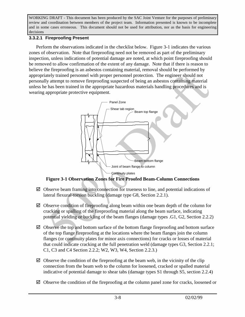
WORKING DRAFT - This document has been produced by the SAC Joint Venture for the purposes of preliminaryreview and coordination between members of the project team. Information presented is known to be incompleteand in some cases erroneous. This document should not be used for attribution, nor as the basis for engineeringdecisions
3-8 02/02/99
3.3.2.1 Fireproofing Present
Perform the observations indicated in the checklist below. Figure 3-1 indicates the variouszones of observation. Note that fireproofing need not be removed as part of the preliminaryinspection, unless indications of potential damage are noted, at which point fireproofing shouldbe removed to allow confirmation of the extent of any damage. Note that if there is reason tobelieve the fireproofing is an asbestos containing material, removal should be performed byappropriately trained personnel with proper personnel protection. The engineer should notpersonally attempt to remove fireproofing suspected of being an asbestos containing materialunless he has been trained in the appropriate hazardous materials handling procedures and iswearing appropriate protective equipment.
Beam top flange
Beam bottom flange
Joint of beam flange to column
Shear tab region
Panel Zone
Continuity plates
Figure 3-1 Observation Zones for Fire Proofed Beam-Column Connections
æ Observe beam framing into connection for trueness to line, and potential indications oflateral flexural-torsion buckling (damage type G8, Section 2.2.1).
æ Observe condition of fireproofing along beam within one beam depth of the column forcracking or spalling of the fireproofing material along the beam surface, indicatingpotential yielding or buckling of the beam flanges (damage types .G1, G2, Section 2.2.2)
æ Observe the top and bottom surface of the bottom flange fireproofing and bottom surfaceof the top flange fireproofing at the locations where the beam flanges join the columnflanges (or continuity plates for minor axis connections) for cracks or losses of materialthat could indicate cracking at the full penetration weld (damage types G3, Section 2.2.1;C1, C3 and C4 Section 2.2.2; W2, W3, W4, Section 2.2.3.)
æ Observe the condition of the fireproofing at the beam web, in the vicinity of the clipconnection from the beam web to the column for loosened, cracked or spalled materialindicative of potential damage to shear tabs (damage types S1 through S5, section 2.2.4)
æ Observe the condition of the fireproofing at the column panel zone for cracks, loosened or

WORKING DRAFT - This document has been produced by the SAC Joint Venture for the purposes of preliminaryreview and coordination between members of the project team. Information presented is known to be incompleteand in some cases erroneous. This document should not be used for attribution, nor as the basis for engineeringdecisions
3-9 02/02/99
spalled material, indicative of damage to the panel zone or continuity plates (damagetypes P1 through P8, Section 2.2.5)
æ Observe the flanges of the column at and beneath the joint with the beam flange forloosened, spalled or cracked material, indicative of fractures, buckled or yielded sections(damage types C1, C3, C4, C6, Section 2.2.6)
æ Observe the column flange in the area immediately above the bottom beam flange forloosened, spalled or cracked material, indicative of a potential divot type fracture of thecolumn material (damage type C2, Section 2.2.2)
Commentary: The presence of fireproofing will tend to obscure many types ofdamage, unless the damage is very severe. However, removal of fireproofing canbe a difficult and time consuming process. For the purposes of preliminaryinspection in buildings with fireproofing, inspection is limited to that readilyobservable with the fire proofing in place. Removal of fireproofing and morecareful visual inspection in such buildings is limited to inspections performed aspart of detailed evaluations, in accordance with Chapters 3 and 4 of theseguidelines. An exception is the case when observation indicates that thefireproofing has noticeably cracked, spalled or loosened, indicating that damagehas probably occurred to the steel framing beneath. In this case, removal offireproofing is recommended as part of the preliminary inspection to determinethe extent of damage.
In most buildings constructed prior to 1979, the original fireproofingmaterials commonly contained friable asbestos fibers. Disturbing such materialwithout wearing suitable breathing apparatus can result in a significant healthhazard both to the person performing the work and also to others located in thearea. For this reason, owners have been gradually addressing these hazardseither by encapsulating such fireproofing, to prevent it from being disturbed, orreplacing it with non-hazardous materials. In buildings constructed prior to1979, the engineer should not permit fireproofing to be removed without properlytrained personnel using appropriate procedures unless the owner can presentsuitable evidence that the material does not contain friable asbestos.
3.3.2.2 Bare Steel
Preliminary inspection of framing connections in buildings that do not have fireproofing inplace on the structural steel, or in which it has been removed should include the complete jointpenetration (CJP) groove welds connecting both top and bottom beam flanges to the columnflange, including the backing bar and the weld access holes in the beam web; the shear tabconnection, including the bolts, supplemental welds and beam web; the column’s web panelzone, including doubler plates; and the continuity plates and continuity plate welds (see Figure 2-2).

WORKING DRAFT - This document has been produced by the SAC Joint Venture for the purposes of preliminaryreview and coordination between members of the project team. Information presented is known to be incompleteand in some cases erroneous. This document should not be used for attribution, nor as the basis for engineeringdecisions
3-10 02/02/99
Beam
Column
Backing
Shear TabSupplemental weld
PanelZone
Continuity Plates
Figure 5-3 Components of Moment Connection
The inspection should be by visible means. Observe all exposed surface for cracks, buckling,yielding, and loosened or broken bolts. The area inspected should include that portion of thebeam within a distance db of the face of the column, that portion of the column below theconnection and within a distance dc of the bottom beam flange, the panel zone and all bolts andplates within these regions. Sections 2.2.1 through 2.2.6 indicate the types of damage that maybe present. All damage observed should be recorded according to the classification indicated inthose sections, and recorded in sketch form.
Note that visual inspection should not be performed casually. After a fracture forms in steelframing, it can close up again under further loading of the building. Such “closed” fractures,though obscure, can typically be detected by careful observation, sometimes aided with touch todetect roughness in the surface in the vicinity of a potential fracture. In some cases, it may benecessary to use methods of NDT, such as Ultrasonic Testing or Liquid Dye Penetrant to confirmthe presence of such cracks. Such confirmation can be performed as part of the more detailedinspections undertaken as part of either a level 1 detailed evaluation (Chapter 4) or a level 2detailed evaluation (Chapter 5).
Certain types of damage (C2, C3, C5, Section 5.3.2; W2, W3 Section 2.2.3) may beimpossible to detect by visual observation alone, as the presence of weld backing at the undersideof the beam flange will obscure the presence of the fracture. The presence of a gap between thebottom edge of the backing and the column flange is one indication of the potential presence ofsuch damage. If such a gap is present it may be possible to explore the presence of concealedfractures by inserting a feel gauge into the gap to determine its depth. If the feeler gauge can beinserted to a depth that exceeds the backing thickness, a fracture should be assumed to bepresent. NDT will be required to confirm the extent of such damage, and can be performed aspart of the more detailed evaluation.

WORKING DRAFT - This document has been produced by the SAC Joint Venture for the purposes of preliminaryreview and coordination between members of the project team. Information presented is known to be incompleteand in some cases erroneous. This document should not be used for attribution, nor as the basis for engineeringdecisions
3-11 02/02/99
3.3.3 Data Reduction and Assessment
Following the collection of data on a building, as outlined in Sections 3.3.1 and 3.3.2, it isnecessary to form a preliminary opinion as to the probability that the building has sustaineddamage, the likely severity of the damage, and the nature of appropriate following actions. Thefollowing sections provide minimum recommendations in this regard. The structural engineer,may on the basis of the evaluated data, or his/her own engineering judgment make a moreconservative assessment.
3.3.3.1 Finding of Dangerous Condition
An assessment should be made that a building has been extensively damaged and ispotentially hazardous, if any of the following conditions are observed:
• permanent inter-story drift in any level of 0.4% or greater
• unexpected severe damage to architectural elements or significant period lengthening ofthe building is observed in aftershocks.
• visual inspections of steel framing indicate the presence of a number of fractures of types:G4, G7, C2, C3, C6, C7, W3, W3, S1, S2, S3, S4, S5, S6, P3, P5, P6, P7 or P9
In the event that any of the above conditions is detected the building should be assessed on apreliminary basis as conforming to damage class Red-1, of Table 3-1. A detailed evaluationshould be recommended and notification should be made advising against continued occupancyuntil a more detailed determination of structural condition can be completed. Refer to Table 3-1.
3.3.3.2 Finding of Damaged Condition
If none of the conditions indicated in Section 2.3.2.1 are determined to exist, and one or moreof the conditions indicated in this Section are present, an assessment should be made that thebuilding has potentially sustained significant damage.
• permanent inter-story drift greater than 0.25% of story height is observed
• significant architectural or structural damage is observed in the building
• one or more columns of the building have noticeably settled relative to adjacent columns
• entry to the building has been limited by the building official because of earthquakedamage, regardless of the type or nature of the damage
• the building employs fracture-vulnerable moment-resisting connections and:
⇒ ground motion exceeds the PGA limits indicated in Table 3-2, or;

WORKING DRAFT - This document has been produced by the SAC Joint Venture for the purposes of preliminaryreview and coordination between members of the project team. Information presented is known to be incompleteand in some cases erroneous. This document should not be used for attribution, nor as the basis for engineeringdecisions
3-12 02/02/99
⇒ significant structural damage is observed in one or more WSMF structures locatedwithin 1 kilometer of the building on sites with similar or more firm soil profiles; or
⇒ significant structural damage is observed to one or more modern, apparently well-designed structures (of any material) within 1 kilometer of the building and on siteswith similar or more firm soil profiles; or
⇒ for an earthquake having a magnitude of 6.5 or greater, the structure is either within 5kilometers of the trace of a surface rupture or within the vertical projection of therupture area when no surface rupture has occurred.
In the event that any of the conditions indicated above is found to exist the building should beassessed on a preliminary basis as conforming to damage class Yellow-3, of Table 3-1. Adetailed evaluation should be recommended and notification should be made advising ofpotentially significant damage and suggesting caution be exercised with regard to continuedoccupancy.
Commentary: A building should be considered to have fracture vulnerablemoment-resisting connections if detailing of the connections is comprised ofdirect connection of the beam flanges to the columns with complete jointpenetration welds, and the building was constructed prior to 1994. Similarly,beam-column connection details where the welded joints are not capable ofdeveloping the full capacity of the connected elements (e.g. welds of beam flangesto columns that employ fillet welds or partial penetration groove welds) should beconsidered to be fracture-critical.
In the above, the term “significant” has been used without definition orquantification. The intent is to use known damage as an indicator of the severityof ground motion experienced. Damage is dependent not only on the strength ofground motion, but also on the quality and condition of the affected construction.Relatively moderate damage to buildings having regular configuration andadequate lateral-force-resisting systems may be a more significant indicator ofstrong ground motion than heavy damage to construction in poor condition orhaving other poor earthquake resisting characteristics. The building officialand/or structural engineer should use their own judgment in determining thesignificance of such damage.
The absence of significant observable damage to WSMF structures on sitesbelieved to have experienced strong ground motion, per Table 3-2, should not beused as an indication that detailed evaluations are not required. Many WSMFbuildings that were structurally damaged by the Northridge and Loma Prietaearthquakes had little apparent damage based on casual observation.
The observed behavior of a building in repeated aftershocks may providesome clues as to whether it has experienced significant structural damage. In

WORKING DRAFT - This document has been produced by the SAC Joint Venture for the purposes of preliminaryreview and coordination between members of the project team. Information presented is known to be incompleteand in some cases erroneous. This document should not be used for attribution, nor as the basis for engineeringdecisions
3-13 02/02/99
instrumented buildings it may be possible to observe a lengthening of the buildingperiod during subsequent earthquakes. In buildings without instruments, theobservation of unexpected large amounts of architectural damage duringsubsequent earthquakes could indicate the presence of previous structuraldamage.
In many cases in the past, buildings have initially been posted as unsafewithout adequate investigation of their condition. Upon reconsideration andtechnical evaluation, such buildings have subsequently been re-posted to allowoccupancy. In such cases, the building need not be considered to have beenposted.
Table 3-2 - Ground Motion Indicators of Potential Damage
1997 NEHRP MCEMap* Short PeriodContour Area
Estimated PeakGround
Acceleration
Level of Damage to Buildings Within 1Kilometer
SS > 0.50 > 0.20g Prevalent partial collapse of URM buildings.High levels of Non-structural damage.Considerable damage to ordinary buildings.
0.20 > SS >0.50 > 0.12g Considerable damage to URM buildings.Slight damage to well-designed buildings.Prevalent non-structural damage.
0.12 < SS < 0.20 > 0.08g Damaged chimneys.Some fallen plasterLimited damage to URM buildings.
* ASCE-7, 1998 and IBC 2000 Maps.
Commentary: A number of techniques are available for estimating thedistribution of ground motion in an area following an earthquake. Frequently,the USGS or other government agencies will develop maps of ground motionintensity, shortly after an earthquake occurs. In regions with a large number ofstrong motion accelerographs present, actual ground motion recordings producethe best method of mapping contours of ground motion. These should be used iflocated near the building, and are located on sites having similar characteristics.In other regions, empirical techniques, such as the use of standard ground motionattenuation relationships (e.g., Joyner and Boore - 1994; Campbell andBazorgnia - 1994) may be required. These can be supplemented with analyticallyderived estimates such as those obtained by direct simulation of the fault ruptureand ground wave propagation. It may be desirable to retain a qualifiedgeotechnical engineer or earth science consultant to make these estimates. Itshould be noted, however, that lacking direct instrumental evidence, site-specificground motion estimates are, at best, uncertain and subject to wide variations

WORKING DRAFT - This document has been produced by the SAC Joint Venture for the purposes of preliminaryreview and coordination between members of the project team. Information presented is known to be incompleteand in some cases erroneous. This document should not be used for attribution, nor as the basis for engineeringdecisions
3-14 02/02/99
depending on the assumptions made. Therefore, the best indicator of the severityof ground motion at a site is often the performance of adjacent construction. Thecriteria of Table 3-2 are provided to help assure that sites which experiencedrelatively strong ground motion are not overlooked as a result of inaccurateestimates of the ground motion severity.
3.3.3.3 Finding of Undamaged Condition
If none of the conditions indicated in Sections 3.3.3.1 or 3.3.3.2 are determined to exist, it isrecommended that the building be assigned a condition assessment of Green-1, Green-2, orGreen-3 of Table 3-1, as appropriate. No further evaluation is recommended.
3.3.4 Reporting and Notification
Following performance of a preliminary evaluation, notification should be made that anevaluation has been performed and a report should be provided to the Owner. The extent ofnotification to be made is dependent upon the jurisdiction of the party performing the evaluation,and upon the condition of the building. If the building has been found to be dangerous, theoccupants ultimately must be notified (in a timely manner).
3.3.4.1 Building Departments
When preliminary evaluations are performed by or on behalf of the Building Official, or otherauthority having jurisdiction, the following notifications should be made:
• A placard should be placed at the main entry to the building indicating that a preliminaryevaluation has been performed, and indicating the assessed condition designation of thebuilding, recommended occupancy restrictions and follow-up actions. Appendix A tothis document includes sample placards.
• If a building has been posted either as "damaged" (condition Yellow-3) or "unsafe"(condition Red-1), additional written notification should be served on the Owner athis/her legal address, indicating the status of the posting, the Owner’s rights and anyactions required on the Owner’s part.
3.3.4.2 Private Consultants
If permitted by the local authority having jurisdiction, a placard should be placed at the mainentry to the building indicating that preliminary evaluation has been performed, the assessedcondition of the building, recommended occupancy restrictions and follow-up actions, and theidentity and affiliation of the person performing the evaluation. Appendix A to this documentincludes sample placards.
A formal report should be prepared indicating the scope of evaluation that has beenperformed, the findings of the evaluation, including a description of any damage encountered, the

WORKING DRAFT - This document has been produced by the SAC Joint Venture for the purposes of preliminaryreview and coordination between members of the project team. Information presented is known to be incompleteand in some cases erroneous. This document should not be used for attribution, nor as the basis for engineeringdecisions
3-15 02/02/99
appropriate post-earthquake condition designation assigned to the building and anyrecommendations for additional evaluation, restrictions of occupancy and/or repair action. Thereport should be submitted to the party requesting the evaluation and to other parties as requiredby law.

WORKING DRAFT - This document has been produced by the SAC Joint Venture for the purposes ofpreliminary review and coordination between members of the project team. Information presented is knownto be incomplete and in some cases erroneous. This document should not be used for attribution, nor as thebasis for engineering decisions
4-1 February 2, 1999
4. Level 1 Detailed Post-Earthquake Evaluations
4.1 Introduction
Detailed evaluation is the second step of the post-earthquake evaluation process, forbuildings with yellow or red condition designations assigned during the preliminaryevaluation. Prior to performing a detailed post-earthquake evaluation, it is recommendedthat a preliminary evaluation, in accordance with the procedures of Chapter 3, beconducted, to avoid the extensive effort required in a detailed evaluation for thosebuildings that are unlikely to have been damaged, and also to permit rapid identificationof those buildings that may have been so severely damaged that they pose a significantthreat to life safety.
Many WSMF buildings damaged in past earthquakes have displayed few outwardsigns of structural or nonstructural damage. Consequently, except for those structureswhich have been damaged so severely that they are obviously near collapse, briefevaluation procedures, such as those of Chapter 3, are unlikely to provide a goodindication of the extent of damage or its consequences. In order to make suchdetermination, it is necessary to perform detailed inspections of the condition of criticalstructural components and connections. If structural damage is found in the course ofsuch inspections, then it is necessary to perform an analysis (either by determining adamage index in accordance with the guidelines of this Chapter, or by performingstructural analysis in accordance with the guidelines of Chapter 5) to determine the effectof discovered damage on the structure’s ability to resist additional loading. This chapterprovides simplified guidelines for a detailed evaluation method in which occupancy andrepair decisions are made based on the calculation of a damage index, related to thedistribution and severity of different types of damage in the structure. An understandingof the distribution of damage in the structure should be obtained by performing visualinspections of critical connections. Although it is preferred that damage indices becalculated based on a determination of the condition of all connections in the building, itis permissible to infer a distribution of damage, and calculate a damage index, based onan appropriately selected sample of connections. Chapter 5 provides an alternative seriesof detailed evaluation guidelines, termed a level 2 evaluation, based on a structuralanalysis of the damaged structure’s ability to resist additional strong ground shaking. Inorder to perform a level 2 evaluation, is necessary to conduct a complete inspection of allfracture critical connections in the building.
Commentary: The level 1 evaluation approach contained in this chapteris based on the methodology presented in FEMA-267. The level 2evaluation is a more comprehensive approach that is compatible with theoverall approach developed by SAC for performance evaluation ofstructures.

WORKING DRAFT - This document has been produced by the SAC Joint Venture for the purposes ofpreliminary review and coordination between members of the project team. Information presented is knownto be incomplete and in some cases erroneous. This document should not be used for attribution, nor as thebasis for engineering decisions
4-2 February 2, 1999
The level 1 detailed evaluation procedure consists of gatheringavailable information on the structure and a multi-step inspectionevaluation, decision and reporting process. Although it is preferable toconduct a complete inspection of all fracture-critical connections, it ispermissible to inspect only a portion of the elements and connections andto use statistical methods to estimate the overall condition of the building.A damage index is introduced to quantify the severity of damage. Thisdamage index is calculated based on individual connection damageindices, di, assigned to the inspected connections. These connectiondamage indices vary between 0 and 10 with 0 representing no significantearthquake damage and 10 representing severe damage. A story leveldamage index, Dmax, is introduced which varies between 0 and 1.0,depending on the severity of damage. Based on the maximum damageindex obtained for any floor level, Dmax, or if full inspections were notmade of all connections, the probability that the damage index exceeds aspecified threshold, guidance is provided to the structural engineerregarding the appropriate damage condition designation as well asdecisions regarding occupancy restrictions and repair actions.
4.2 Data Collection
Prior to performing a detailed inspection and evaluation, available information on thebuilding’s construction should be collected and reviewed. This review should beconducted in a manner similar to that indicated in Section 3.3.1, but extended to includeidentification of the the primary lateral and gravity load-resisting systems, typicaldetailing, presence of irregularities, etc. Pertinent available engineering and geotechnicalreports, including any previous damage survey reports, such as the Preliminary post-earthquake evaluation report prepared in accordance with Chapter 3 of these guidelines,and current ground motion estimates, should also be reviewed. Specifications (includingthe original Welding Procedure Specifications) shop drawings, erection drawings, andconstruction records should be reviewed when available.
When structural framing information is not available, a comprehensive field studymust be undertaken to determine the location and configuration of all lateral force-resisting frames, and the details of their construction including members sizes, materialproperties, and connection configurations.
4.3 Evaluation Approach
Analyses of damaged buildings show that although damage occurs at slightly higherfrequency in locations predicted to have high stress and deformation demands, damagedconnections tend to be widely distributed throughout building frames, often at locationsanalyses would not predict. This suggests that there is some randomness in thedistribution of the damage. To reliably detect all such damage, it is necessary to subject

WORKING DRAFT - This document has been produced by the SAC Joint Venture for the purposes ofpreliminary review and coordination between members of the project team. Information presented is knownto be incomplete and in some cases erroneous. This document should not be used for attribution, nor as thebasis for engineering decisions
4-3 February 2, 1999
each fracture critical connection to detailed inspections. Fracture critical connectionsinclude:
• Moment-resisting beam-column connections in which the beams areconnected to columns using full penetration welds between the beam flangesand column, and in which yield behavior is dominated by the formation of aplastic hinge within the beam at the face of the column, or within the columnpanel zone.
• Splices in the end columns of moment-resisting frames when the splicesconsist of partial penetration groove welds between the upper and lowersections of the column, or of bolted connections that are incapable ofdeveloping the full strength of the upper column in tension.
The inspection of all such connections within a building can be a costly and disruptiveprocess. Although complete visual inspections of fracture critical connections arerecommended as part of a level I evaluation, the evaluation methodology permits arepresentative sample of the critical connections to be selected and inspected. When onlya sample of connections is inspected use is made of statistical techniques to projectdamage observed in the inspected sample to that likely experienced by the entire building.
In order to obtain valid projections of a building’s condition, when the samplingapproach is selected, samples should be broadly representative of the varying conditions(location, member sizes, structural demand) present throughout the building and samplesshould be sufficiently large to permit confidence in the projection of overall buildingdamage. Three alternative methods for sample selection are provided. When substantialdamage is found within the sample of connections, additional connections are inspectedto provide better, more reliable information on the building condition.
Once the extent of building damage is determined, (or estimated if a samplingapproach is utilized) the structural engineer should assess the residual structural capacityand safety, and determine appropriate repair and/or modification actions. Generalrecommendations are provided, based on calculated damage indices. As an alternative tothis approach, direct application of engineering analysis may also be used (level 2evaluation) as provided for in Chapter 5 of these guidelines.
4.4 Detailed Procedure
Post-earthquake evaluation should be carried out under the direct supervision of astructural engineer. Two alternative procedures are presented below depending onwhether all connections in the building are inspected, or if only a sample of theconnections in the building are inspected. Section 4.4.1 describes the procedure when allconnections are inspected. Section 4.4.2 describes the procedure when a sample ofconnections are inspected.

WORKING DRAFT - This document has been produced by the SAC Joint Venture for the purposes ofpreliminary review and coordination between members of the project team. Information presented is knownto be incomplete and in some cases erroneous. This document should not be used for attribution, nor as thebasis for engineering decisions
4-4 February 2, 1999
Commentary: As used in these guidelines, the term “connection” meansthat assembly of elements including the beam, clip plates, bolts, welds, etc.that connect a single beam to a single column. Interior columns of frameswill typically have two connections (one for each beam framing to thecolumn) at each floor level. Exterior columns of frames will have only oneconnection at each floor level.
4.4.1 Inspect All Connections
The following five step procedure may be used to determine the condition of thestructure and to develop occupancy, repair and modification strategies:
Step 1: All moment-resisting connections in the building are subjected to acomplete visual inspection in accordance with Section 4.4.1.1, withsupplemental nondestructive examination, as suggested by that section.
Step 2: Assign a damage index to each inspected connection in accordance withSection 4.4.1.2.
Step 3: Calculate the damage index at each floor pertinent to lateral forceresistance of the building in each of two orthogonal directions, inaccordance with Section 4.4.1.3. Determine the maximum of the floordamage indices.
Step 4: Based on the calculated damage indices, determine appropriate occupancy,and structural repair strategies, in accordance with Section 4.4.1.4. Ifdeemed appropriate, the structural engineer may conduct detailedstructural analyses of the building in the as-damaged state, to obtainimproved understanding of its residual condition and to confirm that therecommended strategies are appropriate or to suggest alternative strategies.Guidelines for such detailed evaluations are contained in Chapter 5.
Step 5: Report the results of the inspection and evaluation process to the buildingofficial and building owner.
4.4.1.1 Detailed Connection Inspections
In order to perform a detailed inspection of beam-column joints, it is necessary toremove the fireproofing to allow direct visual observation of the connection area.Detailed inspections may be conducted in stages. An initial stage inspection may beperformed by removing only the limited amount of fireproofing indicated in Figure 4-1and following the inspection checklist of Section 4.4.1.1.1. If such initial inspectionindicates the presence or potential presence of damage, than a complete inspection, inaccordance with the checklist of Section 4.4.1.1.2 should be performed. Toaccommodate a complete inspection, removal of fireproofing as indicated in Figure 5-2 is

WORKING DRAFT - This document has been produced by the SAC Joint Venture for the purposes ofpreliminary review and coordination between members of the project team. Information presented is knownto be incomplete and in some cases erroneous. This document should not be used for attribution, nor as thebasis for engineering decisions
4-5 February 2, 1999
necessary. At the discretion of the engineer, a complete inspection in accordance withSection 4.4.1.1.2 may be performed without first performing an initial inspection, perSection 4.4.1.1.1. Refer to Chapter 3 for cautions with regard to removal of fireproofingmaterials.
6”
6”6”
Fireproofing
Exposed surfaces
Figure 4-1 Fireproofing Removal for Initial Connection Inspection
6”
6”12”
Fireproofing
Figure 4-2 Fireproofing Removal for Complete Connection Inspection
The findings of detailed inspections of moment-resisting connections should berecorded on appropriate forms, documenting the location of the connection, the personperforming the inspection, the date of the inspection, the extent of the inspection, themeans of inspection (visual or NDT), the location and type of any observed damage, andif no damage was observed, an indication of this. Appendix A to this Guideline includesforms suggested for this purpose. Detected damage should be classified in accordancewith the system of Chapter 2.

WORKING DRAFT - This document has been produced by the SAC Joint Venture for the purposes ofpreliminary review and coordination between members of the project team. Information presented is knownto be incomplete and in some cases erroneous. This document should not be used for attribution, nor as thebasis for engineering decisions
4-6 February 2, 1999
Commentary: The largest concentration of reported damage following theNorthridge earthquake occurred at the welded joint between the bottomgirder flange and column, or in the immediate vicinity of this joint. To amuch lesser extent, damage was also observed in some buildings at thejoint between the top girder flange and column. If damage at either ofthese locations is substantial, then damage is also commonly found in thepanel zone or shear tab areas. This suggests that it may be appropriate toinitially inspect only the welded joint of the bottom beam flange to thecolumn, and if damage is found at this location to extend the inspection tothe remaining connection components.
4.4.1.1.1 Initial Inspections
Perform the inspections and observations indicated in the checklist below. Prior toperforming the inspection, remove fireproofing, as indicated in Figure 5-1 If there areindications of damage, then perform a complete inspection in accordance with theguidelines of Section 4.4.1.1.2.
æ Observe the beam framing into the connection for trueness to line, and potentialindications of lateral flexural-torsion buckling (damage type G8, Section 2.2.1).
æ Observe condition of fireproofing along the beam within one beam depth of thecolumn for cracking or spalling of the fireproofing material along the beamsurface, indicating potential yielding or buckling of the beam flanges (damagetypes .G1, G2, Section 2.2.1)
æ Observe the top and bottom surface of the exposed beam bottom flange forfractures (damage types G3, G4, Section 2.2.1).
æ Observe the exposed surfaces of the complete joint penetration weld between thebeam bottom flange and column for fractures (damage types W2, W3, W4 Section2.2.3)
æ Observe the exposed surfaces of the column flange for fractures (damage typesC1, C2, C3, Section 2.2.2)
æ Observe the condition at the bottom of weld backing on the bottom flange. Ifgaps are present, insert feeler gauge to detect potential damage (damage types C1,C4, C5, Section 2.2.2)
æ Observe the bottom surface of the top flange fireproofing at the locations wherethe beam flanges join the column flanges (or continuity plates for minor axisconnections) for cracks or losses of material that could indicate cracking at the fullpenetration weld (damage types G3, Section 5.3.1; C1, C3 and C4 Section 2.2.2;W2, W3, W4, Section 2.2.3.)

WORKING DRAFT - This document has been produced by the SAC Joint Venture for the purposes ofpreliminary review and coordination between members of the project team. Information presented is knownto be incomplete and in some cases erroneous. This document should not be used for attribution, nor as thebasis for engineering decisions
4-7 February 2, 1999
æ Observe the condition of the fireproofing at the beam web, in the vicinity of theclip connection from the beam web to the column for loosened, cracked or spalledmaterial indicative of potential damage to shear tabs (damage types S1 throughS5, section 2.2.4)
æ Observe the condition of the fireproofing at the column panel zone for cracks,loosened or spalled material, indicative of damage to the panel zone or continuityplates (damage types P1 through P8, Section 2.2.5)
æ Observe the flanges of the column at and beneath the joint with the beam flangefor loosened, spalled or cracked material, indicative of buckled or yielded sections(damage type C6, Section 2.2.2)
4.4.1.1.2 Detailed Inspections
Perform the inspections and observations indicated in the checklist below. Prior toperforming the inspection, remove fireproofing, as indicated in Figure 5-2. Note thatinspection of the top surface of the top flange of the beam and the adjacent column flangewill typically be obscured by the diaphragm. If inspections from the exposed bottomsurface of the top beam flange indicate a potential for damage to be present, then thediaphragm should be locally removed to allow a more thorough inspection.
æ Observe the beam framing into the connection for trueness to line, and potentialindications of lateral flexural-torsion buckling (damage type G8, Section 2.2.1).
æ Observe condition of fireproofing along the beam within one beam depth of thecolumn for cracking or spalling of the fireproofing material along the beamsurface, indicating potential yielding or buckling of the beam flanges (damagetypes .G1, G2, Section 2.2.1)
æ Observe the top and bottom surface of the exposed beam bottom flange forfractures (damage types G3, G4, Section 2.2.1).
æ Observe the exposed surfaces of the complete joint penetration weld between thebeam bottom flange and column for fractures (damage types W2, W3, W4 Section2.2.3)
æ Observe the exposed surfaces of the column flange for fractures (damage typesC1, C2, C3, Section 2.2.2)
æ Observe the condition at the bottom of weld backing on the top and bottomflange. If gaps are present, insert feeler gauge to detect potential damage (damagetypes C1, C4, C5, Section 2.2.2)
æ Observe the condition of the shear tab for deformation of the tab, fractures ortearing of the welds and loosening or breaking of the bolts (damage types S1

WORKING DRAFT - This document has been produced by the SAC Joint Venture for the purposes ofpreliminary review and coordination between members of the project team. Information presented is knownto be incomplete and in some cases erroneous. This document should not be used for attribution, nor as thebasis for engineering decisions
4-8 February 2, 1999
through S5, section 2.2.4)
æ Observe the column panel zone for cracks, or distortion (damage types P1 throughP8, Section 2.2.5)
æ Observe the exposed flanges of the column for distortion (damage type C6,Section 2.2.2)
4.4.1.2 Damage Characterization
Characterize the observed damage at each of the inspected connections by assigning aconnection damage index, dj, obtained either from Table 4-1a or Table 4-1b. Table 4-1apresents damage indices for individual classes of damage and a rule for combiningindices where a connection has more than one type of damage. Table 4-1b providescombined indices for the more common combinations of damage. Refer to Chapter 2 fordescriptions of the various damage categories.
Table 4-1a - Connection Damage Indices
Type Location Description1 Index2djG1 Girder Buckled Flange 3G2 Girder Yielded Flange 1G3 Girder Top or Bottom Flange fracture in HAZ 5G4 Girder Top or Bottom Flange fracture outside HAZ 5G5 Girder Top and Bottom Flange fracture 10G6 Girder Yielding or Buckling of Web 2G7 Girder Fracture of Web 10G8 Girder Lateral-torsional Buckling 5C1 Column Incipient flange crack (detectable by UT) 3C2 Column Flange tear-out or divot5 8C3 Column Full or partial flange crack outside HAZ 8C4 Column Full or partial flange crack in HAZ 8C5 Column Lamellar flange tearing 5C6 Column Buckled Flange 8C7 Column Fractured column splice 10W2 CJP weld Crack through weld metal exceeding t/4 5W3 CJP weld Fracture at girder interface 5W4 CJP weld Fracture at column interface 5S1a Shear tab Partial crack at weld to column (beam flanges sound) 3S1b Shear tab Partial crack at weld to column (beam flange cracked) 7S2a Shear tab Crack in Supplemental Weld (beam flanges sound) 1S2b Shear tab Crack in Supplemental Weld (beam flange cracked) 7S3 Shear tab Fracture through tab at bolt holes 10S4 Shear tab Yielding or buckling of tab 3S5 Shear tab Damaged, or missing bolts4 6S6 Shear tab Full length fracture of weld to column 10
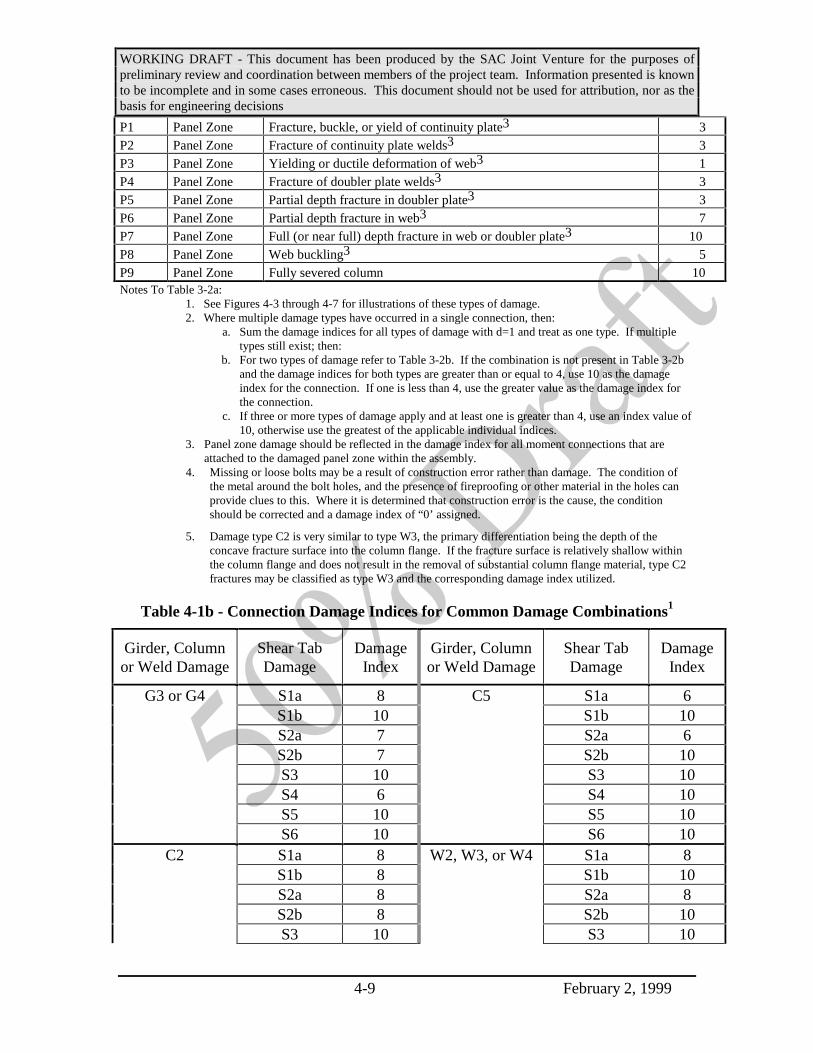
WORKING DRAFT - This document has been produced by the SAC Joint Venture for the purposes ofpreliminary review and coordination between members of the project team. Information presented is knownto be incomplete and in some cases erroneous. This document should not be used for attribution, nor as thebasis for engineering decisions
4-9 February 2, 1999
P1 Panel Zone Fracture, buckle, or yield of continuity plate3 3P2 Panel Zone Fracture of continuity plate welds3 3P3 Panel Zone Yielding or ductile deformation of web3 1P4 Panel Zone Fracture of doubler plate welds3 3P5 Panel Zone Partial depth fracture in doubler plate3 3P6 Panel Zone Partial depth fracture in web3 7P7 Panel Zone Full (or near full) depth fracture in web or doubler plate3 10P8 Panel Zone Web buckling3 5P9 Panel Zone Fully severed column 10Notes To Table 3-2a:
1. See Figures 4-3 through 4-7 for illustrations of these types of damage.2. Where multiple damage types have occurred in a single connection, then:
a. Sum the damage indices for all types of damage with d=1 and treat as one type. If multipletypes still exist; then:
b. For two types of damage refer to Table 3-2b. If the combination is not present in Table 3-2band the damage indices for both types are greater than or equal to 4, use 10 as the damageindex for the connection. If one is less than 4, use the greater value as the damage index forthe connection.
c. If three or more types of damage apply and at least one is greater than 4, use an index value of10, otherwise use the greatest of the applicable individual indices.
3. Panel zone damage should be reflected in the damage index for all moment connections that areattached to the damaged panel zone within the assembly.
4. Missing or loose bolts may be a result of construction error rather than damage. The condition ofthe metal around the bolt holes, and the presence of fireproofing or other material in the holes canprovide clues to this. Where it is determined that construction error is the cause, the conditionshould be corrected and a damage index of “0’ assigned.
5. Damage type C2 is very similar to type W3, the primary differentiation being the depth of theconcave fracture surface into the column flange. If the fracture surface is relatively shallow withinthe column flange and does not result in the removal of substantial column flange material, type C2fractures may be classified as type W3 and the corresponding damage index utilized.
Table 4-1b - Connection Damage Indices for Common Damage Combinations1
Girder, Columnor Weld Damage
Shear TabDamage
DamageIndex
Girder, Columnor Weld Damage
Shear TabDamage
DamageIndex
G3 or G4 S1a 8 C5 S1a 6S1b 10 S1b 10S2a 7 S2a 6S2b 7 S2b 10S3 10 S3 10S4 6 S4 10S5 10 S5 10S6 10 S6 10
C2 S1a 8 W2, W3, or W4 S1a 8S1b 8 S1b 10S2a 8 S2a 8S2b 8 S2b 10S3 10 S3 10

WORKING DRAFT - This document has been produced by the SAC Joint Venture for the purposes ofpreliminary review and coordination between members of the project team. Information presented is knownto be incomplete and in some cases erroneous. This document should not be used for attribution, nor as thebasis for engineering decisions
4-10 February 2, 1999
S4 8 S4 10S5 8 S5 10S6 10 S6 10
C3 or C4 S1a 8S1b 10S2a 8S2b 10S3 10S4 10S5 10S6 10
1. See Table 3-2a, footnote 2 for combinations other than those contained in this table.
More complete descriptions (including sketches) of the various types of defects anddamage are provided in Chapter 2. When the engineer can show by rational analysis thatother values for the relative severities of damage are appropriate, these may be substitutedfor the damage indices provided in the tables. A full reporting of the basis for thesedifferent values should be provided to the building official, upon request.
Commentary: The connection damage indices provided in Table 4-1(ranging from 0 to 10) represent judgmental estimates of the relativeseverities of the various types of damage. Damage severity is judged intwo basic respects, the impact of the damage on global stability andlateral resistance of the frame and the impact of the damage on the localgravity load carrying capacity of the individual connection. An index of 0indicates no impact on either global or local stability while an index of 10indicates very severe damage.
When initially developed, these connection damage indices wereconceptualized as estimates of the connection’s lost capacity to reliablyparticipate in the building’s lateral-force-resisting system in futureearthquakes (with 0 indicating no loss of capacity and 10 indicatingcomplete loss of capacity). However, due to the limited data available, nodirect correlation between these damage indices and the actual residualstrength and stiffness of a damaged connection was ever made. They doprovide a convenient measure, however, of the extent of damage thatvarious connections in a building have experienced.
Analyses conducted by SAC to explore the effect of connectionfractures on the global behavior of frames have revealed that the loss of asingle flange connection (top or bottom) consistently throughout amoment-resisting frame results in only a modest increase in thevulnerability of a structure to developing P-delta instability and collapse.However, if a number of connections develop fractures at both flanges of

WORKING DRAFT - This document has been produced by the SAC Joint Venture for the purposes ofpreliminary review and coordination between members of the project team. Information presented is knownto be incomplete and in some cases erroneous. This document should not be used for attribution, nor as thebasis for engineering decisions
4-11 February 2, 1999
the beam-column connection, significant increase in vulnerability occurs.As a result of this, damage that results in the loss of effectiveness of asingle flange joint to transfer flexural tension stress is assigned arelatively modest damage index of 5, if not combined with other types ofdamage at the connection. Damage types that result in an inability of bothflanges to transfer flexural demands are assigned a high damage index, of10, as are types of damage that could potentially result in impairment of acolumn or beam’s ability to continue to carry gravity loads. Other typesof damage are assigned proportionately lower damage indices, dependingon the apparent effect of this damage on structural stability and loadcarrying capacity.
4.4.1.3 Determine Damage Index at Each Floor for Each Direction of Response
Divide the connections in the building into two individual groups. Each group ofconnections should consist of those connections which are part of frames that provideprimary lateral-force resistance for the structure in one of two orthogonal buildingdirections. For example, one group of connections will typically consist of all thoseconnections located in frames that provide north-south lateral resistance, while the secondgroup will be all those connections located in frames that provide east-west lateralresistance.
For each group of connections, determine the value of the damage index for the groupat each floor, from the equation:
Dn
di
j
j
n
==
∑1
101
(4-1)
where: Di is the damage index at floor “i” for the group.
n is the number of connections in the group at floor level “i” and.
dj is the damage index, per Tables 4-1a and 4-1b for the jth connection in thegroup at that floor
4.4.1.4 Determine Maximum Floor Damage Index
Determine the maximum floor damage index for the building, Dmax, consisting of thelargest of the Di values calculated in accordance with the previous Section.
4.4.1.5 Determine Recommended Recovery Strategies for the Building
Recommended post-earthquake recovery strategies are as indicated in Table 4-2,based on the maximum damage index, Dmax, determined in the previous steps.

WORKING DRAFT - This document has been produced by the SAC Joint Venture for the purposes ofpreliminary review and coordination between members of the project team. Information presented is knownto be incomplete and in some cases erroneous. This document should not be used for attribution, nor as thebasis for engineering decisions
4-12 February 2, 1999
Table 4-2 - Recommended Repair and Modification Strategies
Observation6 Recommended Strategy (Cumulative) NoteDmax>0 Repair all connections discovered to have dj > 5 1,2Dmax > 0.1 Repair all connections discovered to have dj > 2 1,2Dmax> 0.5 A potentially unsafe condition should be deemed to exist unless
a level 2 evaluation is performed and indicates that acceptableconfidence is provided with regard to the lateral stability of thestructure. Notify the building owner of the potentially unsafecondition. Inspect all connections in the building. Repair allconnections with dj > 1.
3
Notes to Table 3-4:
1. Includes damage discovered either as part of Step 2 or Step 3.2. Although repair is recommended only for the more seriously damaged connections, the repair
of all connections that are damaged or otherwise deficient should be considered.3. The determination that an unsafe condition may exist should continue until either:
a. full inspection reveals that the gravity system is not compromised, and that the damageindex at any floor does not exceed 1/2, or
b. level 2 analyses indicate that a dangerous condition does not exist, orc. recommended repairs are completed for all connections having dj > 3.
Commentary: Recommendations to close a damaged building tooccupancy should not be made lightly, as such decisions will havesubstantial economic impact, both on the building owner and tenants. Abuilding should be closed to occupancy whenever, in the judgment of thestructural engineer, damage is such that the building no longer hasadequate lateral-force-resisting capacity to withstand additional strongground shaking, or if gravity load carrying elements of the structureappear to be unstable.
When a building has been damaged, it is recommended that inaddition to repair, consideration also be given to upgrade. A significantportion of structural upgrade costs are a result of the need to moveoccupants out of construction areas as well as the need to selectivelydemolish and replace building finishes and utilities in areas affected bythe work. Often the magnitude of such costs required to implementrepairs are comparable to those that would be incurred in performing anupgrade, permitting improved future performance to be attained withrelatively little increment in construction cost. Structural repair, by itself,will not result in substantial reduction in the vulnerability of the structureto damage from future earthquakes, while upgrade has the potential togreatly reduce future damage and losses.
A companion document to this publication, FEMA-XXX, Evaluationand Upgrade Criteria for Existing Moment-Resisting Steel FrameConstruction provides guidelines for assessing the probable performance

WORKING DRAFT - This document has been produced by the SAC Joint Venture for the purposes ofpreliminary review and coordination between members of the project team. Information presented is knownto be incomplete and in some cases erroneous. This document should not be used for attribution, nor as thebasis for engineering decisions
4-13 February 2, 1999
of steel frame buildings and for designing upgrades to improve thisperformance.
4.4.2 Inspect a Sample of Connections
The following eight-step procedure may be used to determine the condition of thestructure and to develop occupancy, repair and modification strategies when only asample of the building’s critical connections are inspected:
Step 1: The moment-resisting connections in the building are categorized into two ormore groups comprised of connections expected to have similar probabilitiesof being damaged.
Complete steps 2 through 7 below, for each group of connections.
Step 2: Determine the minimum number of connections in the group that should beinspected and select the specific sample of connections to be inspected.
Step 3: Inspect the selected sample of connections using the technical guidelines ofSection 4.4.1 and determine connection damage indices, dj, for each inspectedconnection
Step 4: If inspected connections are found to be seriously damaged, performadditional inspections of connections adjacent to the damaged connections.
Step 5: Determine the average damage index (davg) for connections in the group, andthen the average damage index at a typical floor.
Step 6: Given the average damage index for connections in the group, determine theprobability, P, that the connection damage index for any group, at a floorlevel, exceeds 1/2, and determine the maximum estimated damage index forany floor, Dmax.
Step 7: Based on the calculated damage indices and statistics, determine appropriateoccupancy, structural repair and modification strategies. If deemedappropriate, the structural engineer may conduct detailed structural analyses ofthe building in the as-damaged state, to obtain improved understanding of itsresidual condition and to confirm that the recommended strategies areappropriate or to suggest alternative strategies. Guidelines for such detailedevaluations are contained in Chapter 5.
Step 8: Report the results of the inspection and evaluation process to the buildingofficial and building owner.
Sections 4.4.2.1 through 4.4.2.7 indicate, in detail, how these steps should beperformed.

WORKING DRAFT - This document has been produced by the SAC Joint Venture for the purposes ofpreliminary review and coordination between members of the project team. Information presented is knownto be incomplete and in some cases erroneous. This document should not be used for attribution, nor as thebasis for engineering decisions
4-14 February 2, 1999
Commentary: Following an earthquake structural engineers andtechnicians qualified to perform these evaluations may be at a premium.Prudent owners may want to consider having an investigation planalready developed (Steps 1 and 2) before an earthquake occurs, and tohave an agreement with appropriate structural engineering and inspectionprofessionals and organizations to give priority to inspecting theirbuildings rapidly following the occurrence of an earthquake.
4.4.2.1 Evaluation Step 1 - Categorize Connections by Groups
The welded moment-resisting connections participating in the lateral-force-resistingsystem for the building are to be categorized into a series of connection groups. Eachgroup consists of connections expected to behave in a similar manner (as an example, agroup may consist of all those connections that are highly stressed by lateral forcesapplied in a given direction). As a minimum, two groups of connections should bedefined - each group consisting of connections that primarily resist lateral movement inone of two orthogonal directions. Additional groups should be defined to account forunique conditions including building configuration, construction quality, member size,grade of steel, etc., that are likely to result in substantially different connection behavior,as compared to other connections in the building. Each connection in the building shouldbe uniquely assigned to one of the groups, and the total number of connections in eachgroup determined.
In buildings that have significant torsional irregularity, it may be advisable to defineat least four groups--one group in each orthogonal direction on each side of an assumedcenter of resistance.
For buildings of two or more stories, the roof connections may be excluded from theinitial inspection process. However, when these guidelines recommend inspection of allconnections within a group or building, the roof connections should be inspected.
4.4.2.2 Step 2--Select Samples of Connections for Inspection
Assign a unique identifier to each connection within each group. Consecutive integeridentifiers are convenient to some of the methods employed in this Section.
For each group of connections, select a representative sample for inspection inaccordance with any of Methods A, B, or C, below. If the evaluation is being performedto satisfy a requirement imposed by the building official, a letter indicating thecomposition of the groups, and the specific connections to be inspected should besubmitted to the building official prior to the initiation of inspection. The owner orstructural engineer may at any time in the investigation process elect to investigate moreconnections than required by the selected method. However, the additional connectionsinspected may not be included in the calculation of damage statistics under Step 4

WORKING DRAFT - This document has been produced by the SAC Joint Venture for the purposes ofpreliminary review and coordination between members of the project team. Information presented is knownto be incomplete and in some cases erroneous. This document should not be used for attribution, nor as thebasis for engineering decisions
4-15 February 2, 1999
(Section 4.4.2.4) unless they are selected in adherence to the rules laid out for the originalsample selection, given below.
Commentary: The purpose of inspection plan submittal prior to theperformance of inspections is to prevent a structural engineer, or owner,from performing a greater number of inspections and reporting data onlyon those which provide a favorable economic result with regard tobuilding disposition. The building official need not perform any actionwith regard to this submittal other than to file it for later reference at thetime the structural engineer’s evaluation report is filed. During theinspection process, it may be decided to inspect additional connections tothose originally selected as part of the sample. While additionalinspections can be made at any time, the results of these additionalinspections should not be included in the calculation of the damagestatistics, in Step 5, as their distribution may upset the random nature ofthe original sample selection. If the additional connections are selected ina manner that preserves the distribution character of the original sample,they may be included in the calculation of the damage statistics in Step 5.
4.4.2.2.1 Method A - Random Selection
Connections are selected for inspection such that a statistically adequate randomsample is obtained. The minimum number of connections to be inspected for each groupis determined in accordance with Table 3-3. The following limitations apply to theselection of specific connections:
1. Up to a maximum of 20% of the total connections in any sample may be pre-selected as those expected by rational assessment to be the most prone todamage. Acceptable criteria to select these connections could include:
• Connections shown by a rational analysis to have the highest demand-capacity ratios or at locations experiencing the largest drift ratios.
• Connections that adjoin significant structural irregularities and whichtherefore might be subjected to high localized demands. These include thefollowing irregularities:
- re-entrant corners
- set-backs
- soft or weak stories
- torsional irregularities (connections at perimeter columns)
- diaphragm discontinuities
• Connections incorporating the largest size framing elements.

WORKING DRAFT - This document has been produced by the SAC Joint Venture for the purposes ofpreliminary review and coordination between members of the project team. Information presented is knownto be incomplete and in some cases erroneous. This document should not be used for attribution, nor as thebasis for engineering decisions
4-16 February 2, 1999
2. The balance of the sample should be selected randomly from the remainingconnections in the group.
Up to 10% of the connections in the sample may be replaced by other connections inthe group to which access may more conveniently be made.
Table 3-3 - Minimum Sample Size for Connection Groups
Number of connectionsin Group1
Minimum number ofconnections to be
inspected
Number of Connectionsin Group1
Minimum number ofconnections to be
inspected6 2 200 2710 3 300 3715 4 400 4520 5 500 5330 7 750 7240 8 1000 9950 10 1250 10475 13 1500 120
100 17 2000 147
Note: 1. For other connection numbers use linear interpolation between valuesgiven, rounding up to the next highest integer.
Commentary: The number of connections needed to provide a statisticallyadequate sample depends on the total number of connections in the group.The sample sizes contained in Table 3-3 were developed from MIL-STD-105D, a well established quality control approach that has been widelyadopted by industry.
If relatively few connections within a group are inspected, thestandard deviation for the computed damage index will be large. Thismay result in prediction of excessive damage when such damage does notactually exist. The structural engineer may elect to investigate moreconnections than the minimum indicated in order to reduce the standarddeviation of the sample and more accurately estimate the total damage tothe structure. These additional inspections may be performed at any timein the investigative process. However, care should be taken to preservethe random characteristics of the sample, so that results are not biasedeither by selection of connections in unusually heavy (or lightly) damagedareas of the structure.
It is recognized that in many cases the structural engineer may wish topre-select those connections believed to be particularly vulnerable.However, unless these pre-selected connections are fairly wellgeometrically distributed, a number that is more than about 20% of thetotal sample size will begin to erode the validity of the assumption of

WORKING DRAFT - This document has been produced by the SAC Joint Venture for the purposes ofpreliminary review and coordination between members of the project team. Information presented is knownto be incomplete and in some cases erroneous. This document should not be used for attribution, nor as thebasis for engineering decisions
4-17 February 2, 1999
random selection of the sample. If the structural engineer has acompelling reason for believing that certain connections are most likely tobe damaged, and that more than 20% should be pre-selected on this basis,the alternative approach of Method C should be used.
It is recognized that there is often a practical incentive to selectconnections that are in specific unoccupied or more accessible areas. It issuggested that no more than 10% of the total sample be composed ofconnections pre-selected for this reason. These connections, rather thanhaving a higher disposition for damage, might well have a lower thanaverage tendency to be damaged. An excessive number of this type of pre-selected connection would quickly invalidate the basic assumption ofrandom selection. It is also recognized that during the inspection processconditions will be discovered that make it impractical to inspect aparticular connection, e.g., the architectural finishes are more expensiveto remove and replace than in other areas, or a particular tenant isunwilling to have their space disturbed. However, as discussed above, notmore than 10% of the total connections inspected should be selected basedon convenience.
There are a number of methods available for determining therandomly selected portion of the sample. To do this, each connection inthe group (excluding pre-selected connections) should be assigned aconsecutive integer identifier. The sample may then be selected with theuse of computer spread sheet programs - many of which have a routine forgeneration of random integers between specified limits, published lists ofrandom numbers, or by drawing of lots.
4.4.2.2.2 Method B - Deterministic Selection
Connections are selected to satisfy the following criteria:
1. At least one connection is selected on every column face of every line ofmoment-resisting framing in the group;
2. At least one connection is selected on every floor from every frame;
3. No more than 50% of the connections in a sample may be selected from anyfloor or column face than would be done if the number of inspectedconnections was equally apportioned among either the column faces or floors;and
Up to 10% of the connections in the sample may be replaced by other connections inthe same frame and group to which access may more conveniently be made.

WORKING DRAFT - This document has been produced by the SAC Joint Venture for the purposes ofpreliminary review and coordination between members of the project team. Information presented is knownto be incomplete and in some cases erroneous. This document should not be used for attribution, nor as thebasis for engineering decisions
4-18 February 2, 1999
Commentary: It is recognized that in many cases the structural engineermay be reluctant to select connections in a random manner, as providedby Method A. For those cases, Method B is acceptable since it assuresthat every floor and every column is inspected at least once. Thestructural engineer may select any combination of connections to beinspected that meets these criteria; notwithstanding, care should beexercised to assure that these allowances are not used to subvert the intentof the inspection process to determine the degree of damage to thebuilding, if any.
4.4.2.2.3 Method C - Analytical Selection
Connections are selected for inspection in accordance with the following criteria:
1. The minimum number of connections within the group to be inspected is asindicated in Table 3-3.
2. Up to 60% of the connections may be selected based on the results of rationalanalysis indicating those connections most likely to be damaged.
3. The remaining connections in the group to be inspected are selected such thatthe sample contains connections distributed throughout the building, includingupper, middle and lower stories. The rules of Section 4.4.2.2.1 should befollowed in a general way.
Prior to initiation of the inspections, the rational analysis and list of connections to beinspected should be subjected to a qualified independent third party review in accordancewith Section 4.6. The peer review should consider the basis for the analysis, consistencyof the assumptions employed, and assure that overall, the resulting list of connections tobe inspected provides an appropriate sampling of the building’s connections.
During the inspection process, up to 10% of the connections in the sample may bereplaced by other connections to which access may more conveniently be made.Substitution for more than 10% of the connection sample may be made provided that theindependent third party reviewer concurs with the adequacy of the resulting revisedsample.
For buildings designed and constructed following the 1994 Northridge earthquake,and conforming to the recommendations contained in Chapter 7 of FEMA-267, orconforming to the design recommendations for Special Moment Resisting Framescontained in the 1997 or later edition of the NEHRP Provisions, the scope of inspectionmay be reduced to 1/2 the number of connections recommended in the following sections.If in the course of this reduced scope of inspection, significant structural damage is found(damage to any connection with a damage index per Table 4-1(a or b) that is greater than5), then full inspections in accordance with the following sections should be performed.

WORKING DRAFT - This document has been produced by the SAC Joint Venture for the purposes ofpreliminary review and coordination between members of the project team. Information presented is knownto be incomplete and in some cases erroneous. This document should not be used for attribution, nor as thebasis for engineering decisions
4-19 February 2, 1999
Commentary: In analyses conducted of damaged buildings, there hasbeen a generally poor correlation of the locations of damage and thelocations of highest demand predicted by analysis. This is primarilyattributed to the fact that the propensity for a fracture to initiate in aconnection is closely related to the workmanship present in the weldedjoints, which tends to be a randomly distributed quantity. Moreover,typical analysis methods do not capture the complex nonlinear stress statethat occurs in actual connections. However, there has been somecorrelation. Analysis is a powerful tool to assist the structural engineer inunderstanding the expected behavior of a structure, damaged orundamaged. The specific analysis procedure used should be tailored tothe individual characteristics of the building. It should includeconsideration of all building elements that are expected to participate inthe building’s seismic response, including, if appropriate, elements notconsidered to be part of the lateral-force-resisting system. The groundmotion characteristics used for the analysis should not be less than thatrequired by the building code for new construction, and to the extentpractical, should contain the spectral characteristics of the actual groundmotion experienced at the site. Qualified independent review isrecommended to assure that there is careful consideration of the basis forthe selection of the connections to be inspected and that a representativesample is obtained.
4.4.2.3 Step 3--Inspect the Selected Samples of Connections
All moment-resisting connections within each sample are to be visually inspected asindicated in Section 4.4.1.1. Where visual inspection indicates the potential for damagethat is not clearly visible, further investigation using nondestructive examinationtechniques should be performed. Characterize all damage discovered by visual inspectionand/or nondestructive examination for each inspected connection as described in Section4.4.1.1 An individual data sheet should be filled out for each connection inspection,recording its location and conditions observed. In addition, plan and elevation sketchesfor the building’s structural system should be developed and conditions of observeddamage recorded on these sketches.
Commentary: The largest concentration of reported damage following theNorthridge earthquake occurred at the welded joint between the bottomgirder flange and column, or in the immediate vicinity of this joint. To amuch lesser extent, damage was also observed in some buildings at thejoint between the top girder flange and column. If damage at either ofthese locations is substantial, then damage is also commonly found in thepanel zone or shear tab areas.
For a level 1 evaluation, these Guidelines permit inspection, by visualmeans, of all of the potential damage areas for a small representative

WORKING DRAFT - This document has been produced by the SAC Joint Venture for the purposes ofpreliminary review and coordination between members of the project team. Information presented is knownto be incomplete and in some cases erroneous. This document should not be used for attribution, nor as thebasis for engineering decisions
4-20 February 2, 1999
sample of the connections in the building. Most of the damage reported inbuildings following the Northridge earthquake consisted of fractures thatinitiated at the roots of complete joint penetration welds joining beamflanges to column flanges, and which then propagated through the weld orbase metal, leaving a trace that was generally detectable by careful visualexamination. Careful visual examination requires removal of allobscuring finishes and fireproofing, and examination from a range of afew inches. Most fractures are visually evident. However, some fracturesare rather obscure since deformation of the building following the onset offracture can tend to close up the cracks. In some cases, it may beappropriate to use magnifying glasses or other means to verify thepresence of fractures. If doubt exists as to whether a surface indication isreally a fracture, liquid dye penetrants and other forms of nondestructiveexamination can be used to confirm the presence of a fracture.
Some types of fractures extend from the root of the beam flange weldinto the column flange and may not be detectable by visual examination.Such fractures, typified by types C3 and C5 (see section 5.3.2) can only bedetected by removal of the backing, or by nondestructive examination.Often, when such fractures are present, a readily visible gap can bedetected between the base of the backing and the column flange. Wheresuch indications are present, consideration should be given to the use ofultrasonic testing (UT) to determine if hidden fractures are present.
The practice of inspecting a small sample of the total connectionspresent in a building, in order to infer the probable overall condition ofthe structure is consistent with that followed by most engineers in the LosAngeles area, following the Northridge Earthquake. However, the typicalpractice following that event included the extensive use of UT in additionto visual inspection. This UT revealed a number of apparent conditions ofdamage at the roots of the full penetration welds between beam andcolumn flanges. These conditions, which were quite widespread weretypically reported by testing agencies and engineers as damage. Thispractice was encouraged by the FEMA-267 guidelines which classifiedroot indications as type W1 “damage”.
As a result of limitations in the accuracy of ultrasonic testingtechniques it was often found upon removal of weld backing material toallow repair of these root conditions, that the actual condition of the weldroot was significantly different that indicated by the UT. Sometimes, noflaws at all were found at the roots of welds reported to have W1conditions while in other cases, the size and location of actual flaws wasfound to be significantly different than that indicated by the UT.
In the time since, substantial evidence has been gathered that suggests

WORKING DRAFT - This document has been produced by the SAC Joint Venture for the purposes ofpreliminary review and coordination between members of the project team. Information presented is knownto be incomplete and in some cases erroneous. This document should not be used for attribution, nor as thebasis for engineering decisions
4-21 February 2, 1999
that many of the W1 conditions reported following the Northridgeearthquake were not damage at all but rather, construction defectsincluding slag inclusions and lack of fusion that had never been detectedduring the original construction quality control and quality assuranceprocesses. For these reasons, these guidelines have de-emphasized,relative to the recommendations of FEMA-267, the importance ofemploying NDT in the post-earthquake inspection process.
Inspections may be terminated when at least 50% of the connections selected for eachsample have been inspected if:
1) the inspections have progressed in a manner that retains an adequately randomnature and distributed geometry for those connections that are inspected (adistribution throughout the building that is acceptable to the building official);and
2) no connections with damage indices dj > 5 (Table 3-2a or b) are discovered;and,
3) not more than 10% of the total connections inspected are discovered to have dj> 2.
If all of these conditions are not met, then inspections should be completed for allconnections contained in all samples.
4.4.2.4 Damage Characterization
The observed damage at each of the inspected connections is characterized byassigning a connection damage index, dj, obtained either from Table 4-1a or Table 4-1b.Table 4-1a presents damage indices for individual classes of damage and a rule forcombining indices where a connection has more than one type of damage. Table 4-1bprovides combined indices for the more common combinations of damage. Refer toChapter 2 for descriptions of the various damage types.
Commentary: The connection damage indices provided in Table 4-1(ranging from 0 to 10) represent judgmental estimates of the relativeseverities of the various types of damage. Damage severity is judged intwo basic respects, the impact of the damage on global stability andlateral resistance of the frame and the impact of the damage on the localgravity load carrying capacity of the individual connection. An index of 0indicates no impact on either global or local stability while an index of 10indicates very severe damage.
When initially developed, these connection damage indices wereconceptualized as estimates of the connection’s lost capacity to reliably

WORKING DRAFT - This document has been produced by the SAC Joint Venture for the purposes ofpreliminary review and coordination between members of the project team. Information presented is knownto be incomplete and in some cases erroneous. This document should not be used for attribution, nor as thebasis for engineering decisions
4-22 February 2, 1999
participate in the building’s lateral-force-resisting system in futureearthquakes (with 0 indicating no loss of capacity and 10 indicatingcomplete loss of capacity). However, due to the limited data available, nodirect correlation between these damage indices and the actual residualstrength and stiffness of a damaged connection was ever made. They doprovide a convenient measure, however, of the extent of damage thatvarious connections in a building have experienced.
Analyses conducted by SAC to explore the effect of connectionfractures on the global behavior of frames have revealed that the loss of asingle flange connection (top or bottom) consistently throughout amoment-resisting frame results in only a modest increase in thevulnerability of a structure to developing P-delta instability and collapse.However, if a number of connections develop fractures at both flanges ofthe beam-column connection, significant increase in vulnerability occurs.As a result of this, damage that results in the loss of effectiveness of asingle flange joint to transfer flexural tension stress is assigned arelatively modest damage index of 5, if not combined with other types ofdamage at the connection. Damage types that result in an inability of bothflanges to transfer flexural demands are assigned a high damage index, of10, as are types of damage that could potentially result in impairment of acolumn or beam’s ability to continue to carry gravity loads, aftershocks orother future events. Other types of damage are assigned proportionatelylower damage indices, depending on the apparent effect of this damage onstructural stability and load carrying capacity.
4.4.2.5 Step 4--Inspect Connections Adjacent to Damaged Connections
Perform additional inspections of moment-resisting connections near connectionswith significant damage as follows:
1) when a connection is determined to have a damage index dj > 5, inspect allmoment-resisting connections immediately adjacent (above and below, to theleft and right) to the damaged connection in the same moment frame (SeeFigure 4-3). Also inspect any connections for beams framing into the columnin the transverse direction at that floor level, at the damaged connection.
2) when a connection is determined to have a damage index dj > 9, inspect thetwo moment-resisting connections immediately adjacent (above and below, tothe left and right) to the damaged connection in the same moment frame (SeeFigure 4-4). Also inspect any connections for beams framing into the columnin the transverse direction at that floor level at the damaged connection.

WORKING DRAFT - This document has been produced by the SAC Joint Venture for the purposes ofpreliminary review and coordination between members of the project team. Information presented is knownto be incomplete and in some cases erroneous. This document should not be used for attribution, nor as thebasis for engineering decisions
4-23 February 2, 1999
Frame Elevation Floor Plan
Damaged moment - resisting connection with dj > 5Adjacent moment - resisting connection - to be inspectedTransverse connection - to be inspected
Figure 4-3 - Inspection of Connections Adjacent to Damaged Connection (dj > 5)
Frame Elevation Floor Plan
Damaged moment - resisting connection with dj > 9Adjacent moment - resisting connection - to be inspectedTransverse connection - to be inspected
Figure 4-4 - Inspection of Connections Adjacent to Damaged Connection (dj > 9)
Assign damage indices, dj, per Tables 4-1a and 4-1b, to each additional connectioninspected. If significant damage is found in these additional connections (dj > 5), theninspect the connections near these additional connections, as indicated in 1) and 2) above.Continue this process, until one of the following conditions occurs:
a) The additional connection inspections do not themselves trigger moreinspections, or
b) All connections in the group have been inspected. In this case, proceed withthe evaluation of damage indices for this group in accordance with theguidelines of Section 4.4.1.

WORKING DRAFT - This document has been produced by the SAC Joint Venture for the purposes ofpreliminary review and coordination between members of the project team. Information presented is knownto be incomplete and in some cases erroneous. This document should not be used for attribution, nor as thebasis for engineering decisions
4-24 February 2, 1999
The results of these added connection inspections, performed in this step are notincluded in the calculation of average damage index davg per Section 4.4.2.6 but areincluded in the calculation of the maximum likely damage index Dmax and probability ofexcessive damage, P, per Section 4.4.2.7.
4.4.2.6 Step 5--Determine Damage Statistics for Each Group
For each group of connections, determine the estimated average value of the damageindex for the group (davg) and its standard deviation (σ) from the equations:
d1
n
d
10avgj
j 1
n
==∑ (4-2)
σ =−
−
=∑1
1 101
2
n
dd
j
avgj
n
(4-3)
where: n is the number of connections in the sample selected for inspection under step 2(Section 4.4.2.2), and.
dj is the damage index, per Tables 4-1a and 4-1b for the jth inspected connection inthe sample
The additional connections selected using the procedure of Section 4.4.2.5 (Step 4)are not included in the above calculation.
4.4.2.7 Step 6--Determine the Probability that the Connections in a Group at a FloorLevel Sustained Excessive Damage
In this procedure, the maximum damage index at a floor Dmax is estimated based onthe damage indices determined for the connections actually inspected, and the probabilityP that Dmax exceeds a value of 1/2 is determined.
First determine the average damage index at a typical floor D and its standarddeviation S from the equations:
D d avg= (4-4)
Sk
= σ(4-5)
where k is the total number of connections (both inspected and not inspected) in thegroup at a typical floor.
WORKING DRAFT - This document has been produced by the SAC Joint Venture for the purposes ofpreliminary review and coordination between members of the project team. Information presented is knownto be incomplete and in some cases erroneous. This document should not be used for attribution, nor as thebasis for engineering decisions
4-25 February 2, 1999
Then, determine the probability P that the set of connections within the group at anyfloor has had a cumulative damage index that is greater than or equal to 1/2. This may bedone by using the parameters D and S to calculate a factor “b,” which represents thenumber of multiples of the standard deviation of a Normal distribution above the meanthat would be required to exceed 1/2. The factor “b” is calculated from the equation:
( )b D S= −12 (4-6)
Using the value of “b” calculated from equation 4-6, determine Pf, from Table 4-4. Pfis the probability that if all connections had been inspected, the cumulative damage indexat any floor would have been found to exceed 1/2. If the probability Pf is high, thisstrongly suggests the possibility that there has been a significant reduction in seismicresisting capacity.
Then determine the probability P that if all connections within the group had beeninspected, the connections within the group on at least one floor (out of q total floors inthe group) would have been found to have a cumulative damage index of 1/2 or morefrom the equation:
P Pfq= − −1 1( ) (4-7)
Table 4-4 - Pf as a function of parameter “b”
“b” Pf - (%) “b” Pf - (%)-1.2816 90 1.2265 11-0.8416 80 1.2816 10-0.5244 70 1.3408 9-0.2533 60 1.4051 80.0000 50 1.4395 7.50.2533 40 1.4758 70.5244 30 1.5548 60.8416 20 1.6449 50.8779 19 1.7507 40.9154 18 1.8808 30.9542 17 1.9600 2.50.9945 16 2.0537 21.0364 15 2.1701 1.51.0803 14 2.3263 11.1264 13 3.0962 .11.1750 12 3.7190 .01
* Note - Intermediate values of Pf may be determined by linear interpolation
Finally, for each floor i in the group for which an inspection has been performed,determine the cumulative damage index, Di, from the equation:

WORKING DRAFT - This document has been produced by the SAC Joint Venture for the purposes ofpreliminary review and coordination between members of the project team. Information presented is knownto be incomplete and in some cases erroneous. This document should not be used for attribution, nor as thebasis for engineering decisions
4-26 February 2, 1999
( )D
k m d
k
1
k
d
10ii i avg
i i
j
j 1
mi
=−
+
=∑ (4-8)
where: ki is the total number of connections in the group at floor imi is the number of inspected connections in the group at floor i includingthe additional connections inspected under step 4
Take Dmax as the largest of the Di values calculated for each floor of the group.
Commentary: The criterion for damage evaluation used in this Guidelineis to assume that a cumulative damage index of 1/2 marks the threshold atwhich a structure may become dangerous. Such a damage index couldcorrespond to cases where 1/2 of the connections in a building have beenseverely damaged; cases where all of the connections have experiencedmoderate damage; or some combination of these, and therefore representsa reasonable point at which to begin serious consideration of a building’sresidual ability to withstand additional loads.
Although the actual form of the distribution of the probability ofdamage for an individual connection is not known, by the Central LimitTheorem, as the number of connections increases, the distribution ofdamage for a structure tends to a normal distribution, regardless of theform of the distribution for individual connections. Therefore, theprobability that a damage index of 1/2 has been exceeded at a floor, in agroup with k connections may be approximated by determining how manymultiples (b) times the standard deviation (S), when added to the meandamage index (D) equals 1/2. Or, in equation form :
D + bS = 1/2 (4-9)
Solution of this equation for the multiplier “b” results in the requiredrelationship of equation 4-9.
Damage Indices (from Table 4-1) that are largely judgmental are usedto characterize the loss of reliable seismic performance capability ofindividual connections. These indices are added, averaged and otherwisestatistically manipulated for use as an indication of the average damageindex for groups of connections, entire frames and ultimately of the lateralsystem itself. It should be clear that use of such an approximate,judgmentally defined characterization of strength cannot rigorouslycalibrate the loss of lateral resistance, or the residual strength andstiffness of the building.
In spite of the somewhat arbitrary nature of the 1/2 damage indexcriterion and the judgmental nature of the suggested way of testingwhether that criteria has been exceeded, it is believed that the results of

WORKING DRAFT - This document has been produced by the SAC Joint Venture for the purposes ofpreliminary review and coordination between members of the project team. Information presented is knownto be incomplete and in some cases erroneous. This document should not be used for attribution, nor as thebasis for engineering decisions
4-27 February 2, 1999
these procedures will lead to reasonable conclusions in most cases.However, it is always the prerogative of the responsible structuralengineer to apply other rational techniques, such as direct analyses of theremaining structural strength, stiffness, and deformation capacity as averification of the conclusions provided by these procedures. Particularlyin anomalous or marginal cases, such additional checks based onengineering judgment are strongly encouraged .
4.4.2.8 Step 7--Determine Recommended Recovery Strategies for the Building
Recommended post-earthquake recovery strategies are as indicated in Table 4-5,based on the calculated damage indices and statistics determined in the previous steps.

WORKING DRAFT - This document has been produced by the SAC Joint Venture for the purposes ofpreliminary review and coordination between members of the project team. Information presented is knownto be incomplete and in some cases erroneous. This document should not be used for attribution, nor as thebasis for engineering decisions
4-28 February 2, 1999
Table 4-5 - Recommended Condition Designation and Repair Strategies
Observation6 Condition Designation Recommended Strategy(Cumulative)
Note
P>0 or Dmax>0 Green - 3 Repair all connections discoveredto have dj > 5
1,2
P > 5% or Dmax > 0.1 Green - 3 Repair all connections discoveredto have dj > 2
1,2
P > 10 % orDmax> 0.2
Green - 3 Inspect all connections in thegroup. Repair all connections withdj > 2
2
P > 25 % orDmax> 0.5
Red - 2 A potentially unsafe conditionshould be deemed to exist unless alevel 2 evaluation is performed andindicates that acceptableconfidence is provided with regardto the lateral stability of thestructure. Notify the buildingowner of the potentially unsafecondition. Inspect all connectionsin the building. Repair allconnections with dj > 1.
3
Notes to Table 3-4:
1. Includes damage discovered either as part of Step 2 or Step 3.2. Although repair is recommended only for the more seriously damaged connections, the repair
of all connections that are damaged or otherwise deficient should be considered.3. The determination that an unsafe condition may exist should continue until either:
a. full inspection reveals that the gravity system is not compromised, and that the damageindex at any floor does not exceed 1/2, or
b. level 2 analyses indicate that a dangerous condition does not exist, orc. recommended repairs are completed for all connections having dj > 3.
Commentary: The value of P (the probability that the connections on atleast one floor have a cumulative damage index of 1/2 or more) and Dmax
(the maximum damage index at a floor level within a group) weredetermined in Method A by using a random selection process, and thusrepresent a statistically valid basis for the characterization of the damageindex for the group of connections, and thus for the building. Method Bselects the connections by using a specified distribution throughout thebuilding based on forcing selection of connections in every column lineand floor. Method C selects the connections, based on engineeringcharacterization of those most likely to have been damaged, modified toreflect a distribution throughout the structure. While the connectionsselected by Methods B and C are not truly random, they are widelydistributed and have some characteristics of a random distribution. Suchselections are judged to be sufficiently random-like to warrant processingas if the connections were selected randomly. Thus regardless of whether

WORKING DRAFT - This document has been produced by the SAC Joint Venture for the purposes ofpreliminary review and coordination between members of the project team. Information presented is knownto be incomplete and in some cases erroneous. This document should not be used for attribution, nor as thebasis for engineering decisions
4-29 February 2, 1999
method A, B, or C was used, decisions on disposition of the building, andthe need for repair measures can defensibly be based on the values ofthese two key parameters, as determined for each group of connections.
Recommendations to close a damaged building to occupancy shouldnot be made lightly, as such decisions will have substantial economicimpact, both on the building owner and tenants. A building should beclosed to occupancy whenever, in the judgment of the structural engineer,damage is such that the building no longer has adequate lateral-force-resisting capacity to withstand additional strong ground shaking, or ifgravity load carrying elements of the structure appear to be unstable.
When a building has been damaged, it is recommended that inaddition to repair, consideration also be given to upgrade. A significantportion of structural upgrade costs are a result of the need to moveoccupants out of construction areas as well as the need to selectivelydemolish and replace building finishes and utilities in areas affected bythe work. Often the magnitude of such costs required to implementrepairs are comparable to those that would be incurred in performing anupgrade, permitting improved future performance to be attained withrelatively little increment in construction cost. Structural repair, by itself,will not result in substantial reduction in the vulnerability of the structureto damage from future earthquakes, while upgrade has the potential togreatly reduce future damage and losses. Upgrade should be givenespecially strong consideration for those structures that have experiencedsubstantive damage, as evidenced by high calculated Dj’s for relativelymoderate levels of ground shaking.
A companion document to this publication, FEMA-XXX, Evaluationand Upgrade Criteria for Existing Moment-Resisting Steel FrameConstruction provides guidelines for assessing the probable performanceof steel frame buildings and for designing upgrades to improve thisperformance.
4.4.3 Additional Considerations
Regardless of the value calculated for the damage indices, in accordance with theprevious sections, and the recommended actions of Section 4.4.2.8, the engineer shouldbe alert for any damage condition that results in a substantial lessening of the ability ofthe structure as a whole, or of any part of the structure to resist gravity loads. Shouldsuch a condition be encountered, the engineer should take appropriate steps either to limitentry to the affected portion(s) of the structure, or to ensure that adequate shoring isprovide to prevent the onset of partial or total building collapse.

WORKING DRAFT - This document has been produced by the SAC Joint Venture for the purposes ofpreliminary review and coordination between members of the project team. Information presented is knownto be incomplete and in some cases erroneous. This document should not be used for attribution, nor as thebasis for engineering decisions
4-30 February 2, 1999
4.5 Evaluation Report
Upon completion of a detailed evaluation, the responsible structural engineer shouldprepare a written evaluation report and submit it to the person requesting the evaluation,as well as any other parties required by law to receive such a report. This report shoulddirectly, or by attached references, document the inspection program that was performed,and provide an interpretation of the results of the inspection program and a generalrecommendation as to appropriate repair and occupancy strategies. The report shouldinclude but not be limited to the following material:
• Building Address
• A narrative description of the building, indicating plan dimensions, number ofstories, total square feet, occupancy, the type and location of lateral-force-resistingelements. Include a description of the grade of steel specified for beams andcolumns and, if known, the type of welding (SMAW, FCAW, etc.) present.Indicate if moment connections are provided with continuity plates. The narrativedescription should be supplemented with sketches (plans and evaluations) asnecessary to provide a clear understanding of pertinent details of the building’sconstruction. The description should include an indication of any structuralirregularities as defined in the Building Code.
• A description of nonstructural damage observed in the building, especially asrelates to evidence of the drift or shaking severity experienced by the structure.
• If a letter was submitted to the building official before the inspection process wasinitiated that indicated how the connections were to be divided into groups andindicating the specific connections to be inspected, a copy of this letter should beincluded.
• A description of the inspection and evaluation procedures used, includingdocumentation of all instructions to the inspectors, and of the signed inspectionforms for each individual inspected connection.
• A description, including engineering sketches, of the observed damage to thestructure as a whole (e.g., permanent drift) as well as at each connection, keyed tothe damage types in Table 3-2a, photographs should be included for allconnections with damage index di>5.
• Calculations of davg, Di, and Dmax for each group, and if all connections in a groupwere not inspected, Pf and P.
• A summary of the recommended actions (repair and modification measures andoccupancy restrictions).

WORKING DRAFT - This document has been produced by the SAC Joint Venture for the purposes ofpreliminary review and coordination between members of the project team. Information presented is knownto be incomplete and in some cases erroneous. This document should not be used for attribution, nor as thebasis for engineering decisions
4-31 February 2, 1999
The report should include identification of any potentially hazardous conditionswhich were observed, including corrosion, deterioration, earthquake damage, pre-existingrejectable conditions, and evidence of poor workmanship or deviations from the approveddrawings. In addition, the report should include an assessment of the potential impacts ofobserved conditions on future structural performance and recommendations forremediatoin of any adverse conditions. The report should include the Field InspectionReports of damaged connections, as an attachment, and should bear the seal of thestructural engineer in charge of the evaluation.
Commentary: Following completion of the detailed damage assessments,the structural engineer should prepare a written report. The report shouldinclude identification of any potentially hazardous conditions which wereobserved, including earthquake damage, pre-existing rejectableconditions, and evidence of poor workmanship or deviations from theapproved drawings. In addition, the report should include an assessmentof the potential impacts of observed conditions on future structuralperformance. The report should include the field inspection, visualinspection and NDT records, data sheets, and reports as attachments.
The nature and scope of the evaluations performed should be clearlystated. If the scope of evaluation does not permit an informed judgment tobe made as to the extent with which the building complies with theapplicable building codes, or as to a statistical level of confidence that thedamage has not exceeded an acceptable damage threshold, this should bestated.
4.6 Qualified Independent Engineering Review
Independent third party review, by qualified professionals, is recommendedthroughout these Guidelines when alternative approaches to evaluation or design aretaken, or where approaches requiring high degrees of structural engineering knowledgeand judgment are taken. Specifically, it is recommended that qualified engineering reviewbe provided in any of the following cases:
• Where an evaluation is being performed and the engineer elects to selectconnections for inspection by a method other than those provided in theseGuidelines.
• Where the calculated damage index Dmax exceeds 50% and the engineer hasdetermined that an unsafe condition does not exist.
• Where an engineer has decided not to repair damage otherwise recommended tobe repaired by these Guidelines.

WORKING DRAFT - This document has been produced by the SAC Joint Venture for the purposes ofpreliminary review and coordination between members of the project team. Information presented is knownto be incomplete and in some cases erroneous. This document should not be used for attribution, nor as thebasis for engineering decisions
4-32 February 2, 1999
• When any story of the building has experienced a permanent lateral driftexceeding 0.7% of the story height and proposed repairs do not correct thiscondition.
Where independent review is recommended, the analysis and/or design should besubjected to an independent and objective technical review by a knowledgeable reviewerexperienced in the design, analysis, and structural performance issues involved. Thereviewer should examine the available information on the condition of the building, thebasic engineering and reliability concepts, and the recommendations for proposed action.
Commentary: The independent reviewer may be one or more personswhose collective experience spans the technical issues anticipated in thework. When more than one person is collectively performing theindependent review, one of these should be designated the review chairand should act on behalf of the team in presenting conclusions orrecommendations.
Independent third party review is not a substitute for plan checking. Itis intended to provide the structural engineer of record with anindependent opinion, by a qualified expert, on the adequacy of structuralengineering decisions and approaches. The seismic behavior of WSMFstructures is now understood to be an extremely complex issue. Properunderstanding of the problem requires knowledge of structural mechanics,metallurgy, welding, fracture mechanics, earthquake engineering, andstatistics. Due to our limited current state of knowledge, evenprofessionals who possess such knowledge face considerable uncertaintyin making design judgments. Third party review should only be performedby qualified individuals.
4.6.1 Timing of Independent Review
The independent reviewer(s) should be selected prior to the initiation of substantialportions of the design and/or analysis work that is to be reviewed, and coordination of thereview should start as soon as sufficient information to define the project is available.
4.6.2 Qualifications and Terms of Employment
The reviewer should have no other involvement in the project before, during, or afterthe review. The reviewer should be selected and paid by the owner and should have anequal or higher level of technical expertise in the issues involved than the structuralengineer-of-record. The reviewer (or in the case of peer review teams, the review chair)should be a structural engineer who is familiar with governing regulations for the workbeing reviewed. The reviewer should serve through completion of the project and shouldnot be terminated except for failure to perform the duties specified herein. Such

WORKING DRAFT - This document has been produced by the SAC Joint Venture for the purposes ofpreliminary review and coordination between members of the project team. Information presented is knownto be incomplete and in some cases erroneous. This document should not be used for attribution, nor as thebasis for engineering decisions
4-33 February 2, 1999
termination should be in writing with copies delivered to the building official, owner, andstructural engineer-of-record.
4.6.3 Scope of Review
Review activities related to evaluation of the safety condition of a building shouldinclude a review of available construction documents for the building, all inspection andtesting reports, any analyses prepared by the structural engineer of record, the method ofconnection sample selection, and visual observation of the condition of the structure, aswell as review of any mathematical models and analyses performed as part of the post-earthquake evaluation. Review should include consideration of the proposed designapproach, methods, materials, and details.
4.6.4 Reports
The reviewer should prepare a written report to the owner and building official thatcovers all aspects of the structural engineering review performed, including conclusionsreached by the reviewer. Such reports should include statements on the following:
• Scope of engineering review performed with limitations defined.
• The status of the project documents at each review stage.
• Ability of selected materials and framing systems to meet performance criteriawith given loads and configuration.
• Degree of structural system redundancy, ductility, and compatibility, particularlyin relation to lateral forces.
• Basic constructability of structural members and connections (or repairs andmodifications of these elements).
• Other recommendations that would be appropriate to the specific project.
• Presentation of the conclusions of the reviewer identifying any areas which needfurther review, investigation, and/or clarifications.
4.6.5 Responses and Corrective Actions
The structural engineer-of-record should review the report from the reviewer anddevelop corrective actions and other responses as appropriate. Changes during theconstruction/field phases that affect the seismic resistance system should be reported tothe reviewer in writing for action and recommendations.

WORKING DRAFT - This document has been produced by the SAC Joint Venture for the purposes ofpreliminary review and coordination between members of the project team. Information presented is knownto be incomplete and in some cases erroneous. This document should not be used for attribution, nor as thebasis for engineering decisions
4-34 February 2, 1999
4.6.6 Distribution of Reports
All reports, responses, and corrective actions prepared pursuant to this section shouldbe submitted to the building official and the owner along with other plans, specifications,and calculations required. If the reviewer is terminated by the owner prior to completionof the project, then all reports prepared by the reviewer, prior to such termination, shouldbe submitted to the building official, the owner, and the structural engineer-of-recordwithin ten (10) working days of such termination.
4.6.7 Engineer-of-Record
The structural engineer-of-record should retain the full responsibility for the structuraldesign as outlined in professional practice laws and regulations. The independent reviewengineer(s) should not be asked to or be expected to assume any responsibility for thestructural evaluation or subsequent repair designs.
4.6.8 Resolution of Differences
If the structural engineer-of-record does not agree with the recommendations of thereviewer, then such differences should be resolved by the building official in the mannerspecified in the applicable Building Code.

WORKING DRAFT - This document has been produced by the SAC Joint Venture for the purposes ofpreliminary review and coordination between members of the project team. Information presented is knownto be incomplete and in some cases erroneous. This document should not be used for attribution, nor as thebasis for engineering decisions
5-1 February 2, 1999
5. Level 2 Detailed Post-Earthquake Evaluations
5.1 Introduction
Detailed evaluation is the second step of the post-earthquake evaluation process.Prior to performing a detailed post-earthquake evaluation, it is recommended that apreliminary evaluation, in accordance with the Guidelines of Chapter 3, be conducted, toavoid the extensive effort required in a detailed evaluation for those buildings that areunlikely to have been damaged, and also to permit rapid identification of those buildingsthat have been so severely damaged that they pose a significant threat to life safety.
Many WSMF buildings damaged in past earthquakes have displayed few outwardsigns of this damage. Consequently, except for those structures which have beendamaged so severely that they are obviously near collapse, brief evaluation procedures,such as those of Chapter 3, are unlikely to provide a good indication of the extent ofdamage or its consequences. In order to make such determination, it is necessary toperform detailed inspections of the condition of critical structural components andconnections. It may also be necessary to perform an analysis to determine the effect ofdiscovered damage on the structure’s ability to resist additional loading. Chapter 4provides a series of guidelines for a detailed evaluation method in which occupancy andrepair decisions are made based on the calculation of damage indices based on theobserved distribution of damage in the structure. The distribution of damage isdetermined on the basis of detailed inspections of fracture critical connections. Althoughit is preferred that all fracture critical connections be inspected, the procedures of Chapter4 permit inspections to be limited to a representative sample. This chapter providesguidelines for a detailed evaluation processes in which a detailed analytical evaluation ofthe damaged structure’s ability to resist additional strong ground shaking is conducted. Inorder to perform such an analysis it is necessary to inspect all fracture critical connectionsin the building in order to understand their condition.
Commentary: The level 1 evaluation approach of Chapter 4 is based onthe methodology presented in FEMA-267. The level 2 evaluationapproach described in this Chapter is a more comprehensive analyticalapproach that is compatible methodology developed by SAC for designand performance evaluation of WSMF structures.
5.2 Data Collection
Prior to performing a detailed evaluation, the original construction drawings shouldbe reviewed (if available) to identify the primary lateral and gravity load-resistingsystems, typical detailing, presence of irregularities, etc. Pertinent available engineeringand geotechnical reports, including any previous damage survey reports and currentground motion estimates, should also be reviewed. Specifications (including the original

WORKING DRAFT - This document has been produced by the SAC Joint Venture for the purposes ofpreliminary review and coordination between members of the project team. Information presented is knownto be incomplete and in some cases erroneous. This document should not be used for attribution, nor as thebasis for engineering decisions
5-2 February 2, 1999
Welding Procedure Specifications) shop drawings, erection drawings, and constructionrecords should be reviewed when available.
When structural framing information is not available, a comprehensive field studymust be undertaken to determine the location and configuration of all vertical frames, andthe details of their construction including members sizes, material properties, andconnection configurations.
Commentary: It is important to collect data on all framing, whether ornot it was originally intended as part of the design to participate in thelateral force resistance of the structure. Studies have shown that verticalframes provided only for gravity load resistance can provide substantialresidual stiffness and strength in WSMF structures and the analyticalprocedures of this Chapter include direct consideration of such framing.Data collection should obtain sufficient information on this framing, aswell as that intended to provide the structure’s lateral-force resistance topermit an accurate analytical model of the structure to be developed.
In addition to reviewing available documentation, a complete inspection of all criticalframing and connections in the building should be undertaken, to determine theircondition. Connections to be inspected include all fracture-critical moment-resistingframing connections and column splices. The following connections are considered to befracture-critical:
• Moment-resisting beam-column connections in which the beams areconnected to columns using full penetration welds between the beam flangesand column, and in which yield behavior is dominated by the formation of aplastic hinge within the beam at the face of the column, or within the columnpanel zone.
• Splices in the end columns of moment-resisting frames when the splicesconsist of partial penetration groove welds between the upper and lowersections of the column, or of bolted connections that are incapable ofdeveloping the full strength of the upper column in tension.
Section 4.4.1.1 provides guidelines for conducting connection inspections, recordingand for classifying any damage found.
Commentary: Most welded, moment-resisting beam-column connectionsconstructed prior to 1994 will be of the fracture critical type describedhere. Following the 1994 Northridge earthquake guidelines for improvedconnection designs and details were developed and were rapidly adoptedthroughout the western United States, particularly in zones of highseismicity including California, Washington and Alaska. However,fracture critical connections may exist in some post-1994 buildings,

WORKING DRAFT - This document has been produced by the SAC Joint Venture for the purposes ofpreliminary review and coordination between members of the project team. Information presented is knownto be incomplete and in some cases erroneous. This document should not be used for attribution, nor as thebasis for engineering decisions
5-3 February 2, 1999
particularly those constructed in zones of lower seisimicity.
5.3 Evaluation Approach
In a level 2 evaluation, inspections are conducted of all critical structural elementsand connections. An analytical model is then developed for the building representing itsstrength and stiffness in the damaged state. An analysis of the response of this model to arepeat of the initial earthquake event that caused the damage is then conducted todetermine a level of confidence that the building is capable of resisting this groundmotion without collapse. If the analysis indicates sufficient confidence that the buildingwould not collapse in a repeat of the initial earthquake event, building occupancy maycontinue as the building is repaired. If sufficient confidence of the building’s ability toresist the ground motion without collapse is not indicated, then occupancy should belimited or prevented during the repair period.
Commentary: A number of different criteria have historically been used todetermine whether a building has sustained so much damage that it shouldnot continue to remain occupied. In all of these, the decision to post abuilding against occupancy is based on a finding that the building is likelyto endanger life safety if subjected to additional strong ground shaking.Approaches that have most commonly been used in the past include:
• comparison of the building’s residual lateral-force-resistingcapacity with that specified by the building code for design ofstructures
• comparison of the building’s residual lateral-force resistingcapacity with that which existed prior to the onset of damage
• application of the engineer’s judgment as to the extent whichthe building poses an imminent or extreme hazard
Each of these approaches have drawbacks. If a comparison of thebuilding’s residual lateral-force-resisting capacity with that specified bythe building code is used, it will often be found that a building that has notbeen damaged or has only minimal damage falls below the trigger levelthat indicates a “dangerous” condition, just due to the fact that thebuilding was designed to earlier editions of the code that had lessstringent design criteria. This results in a paradox in that engineerstypically do not post building as “unsafe”, even if they have lowcalculated lateral-force-resisting capacity, unless they have been severelydamaged.
The second approach, in which the computed degradation of abuilding’s lateral-force-resisting capacity is used as the measure of

WORKING DRAFT - This document has been produced by the SAC Joint Venture for the purposes ofpreliminary review and coordination between members of the project team. Information presented is knownto be incomplete and in some cases erroneous. This document should not be used for attribution, nor as thebasis for engineering decisions
5-4 February 2, 1999
whether or not a building should be occupied is somewhat more attractivein that it provides a direct measure of the effect of the damage sustainedon the safety of the building and thereby differentiates low strengthconditions that are a result of original design characteristics as opposedto those resulting from damage. However, this approach is also somewhatflawed in that some buildings have significant overstrength and reservecapacity and can sustain substantial reduction in initial capacity withoutbecoming hazardous.
Approaches limited to application of the engineers judgment areattractive to many engineers, but inherently arbitrary. Further, differentengineers will form different judgments as to the hazard that damage hascaused in a building and will recommend different posting actions.
In both of the above analytical approaches, an attempt is generallymade to estimate the adequacy of the building to withstand collapse giventhat ground motion comparable to that used as a basis for design in thebuilding code is experienced. However, building codes are based onhazards that have very long return periods. Such levels of ground shakingare unlikely to occur in the relatively brief period of time, perhaps a yearfollowing a damaging earthquake event, during which a building is eitherrepaired or demolished, and therefore may be excessively conservativewith regard to determining building safety.
Review of statistics of past earthquakes indicates that within therelatively brief period of a year or so following a major earthquake in aregion, the most likely events that the region will experience are of asimilar or reduced magnitude to the original shock. Therefore, theseguidelines recommend evaluation of damaged structures for their abilityto resist collapse (ability to provide Collapse Prevention performance) forsuch an event. For the purposes of accounting for variability in the likelylocations and magnitudes of major after shocks, and also to permitdevelopment of confidence levels for ability of the building to provideCollapse Prevention performance, a one year return period is assumed foran arbitrary after shock, comparable in intensity at the building site to theinitial shock. Variability in ground motion is somewhat arbitrarilyaccounted for by assuming a distribution of likely ground shaking at thebuilding site due to such an aftershock that has a mean value equal to thatwhich caused the original damage and having a coefficient of variation of0.5.
The safety evaluation approach presented in this section is intendedonly for use in assessing whether a building should remain occupied whileit is repaired, based on the probability of collapse during the periodimmediately following the earthquake. It is not intended as tool for
WORKING DRAFT - This document has been produced by the SAC Joint Venture for the purposes ofpreliminary review and coordination between members of the project team. Information presented is knownto be incomplete and in some cases erroneous. This document should not be used for attribution, nor as thebasis for engineering decisions
5-5 February 2, 1999
evaluating the adequacy of building performance over the longer term ofthe building’s remaining life. For guidelines on such performanceevaluations refer to the companion publication, FEMA-XXX Upgrade andEvaluation Criteria for Existing Welded Steel Moment-Resisting Framestructures.
5.4 Field Inspection
Prior to performing an analytical evaluation of building safety, a thorough inspectionof the building should be conducted to determine its condition. This inspection shouldinclude visual inspection of all critical connections including moment-resisting beam-column connections and column splices, supplemented by NDT where visual inspectionreveals the potential damage that can not be quantified by visual means alone. Beam-column connections should be inspected, and the damage recorded, as indicated inSection 4.4.1.
Geologic site hazards such as fault rupture, landslide, rock fall, and liquefaction mayinfluence the damage in a building and also its future performance. A detailed discussionof these hazards is provided in FEMA 273 and should be considered as part of a post-earthquake evaluation. The existing foundation system should be inspected to try to detectwhether or not differential settlement has occurred. Differential movement betweencolumns in a frame element has the potential to place severe demands on the momentconnections.
Commentary: Foundation inspection is typically difficult to accomplishsince most foundations are buried. In most cases, inspection of foundationcondition can be performed by observing floors for indications ofsettlement. Where significant settlements are indicated, local excavationto expose the foundation condition for inspection should be considered.
5.5 Material Properties and Condition Assessment
Knowing the specific mechanical and chemical properties of structural steel structuresis critical to proper evaluation using level 2 methods. Mechanical properties ofcomponent and connection material dictate the structural behavior of the componentunder load. Mechanical properties of greatest interest include the expected yield (Fye) andtensile (Fte) strengths of base and connection materials, modulus of elasticity, ductility,toughness, elongational characteristics, and weldability.
The effort required to determine these properties is related to the availability oforiginal and updated construction documents, original quality of construction,accessibility, and condition of materials and the level of confidence required for theevaluation. For the purpose of level 2 evaluations, material properties should be based onthe information presented on the original construction documents as supplemented by

WORKING DRAFT - This document has been produced by the SAC Joint Venture for the purposes ofpreliminary review and coordination between members of the project team. Information presented is knownto be incomplete and in some cases erroneous. This document should not be used for attribution, nor as thebasis for engineering decisions
5-6 February 2, 1999
Table 4-1, unless such documents are not available, in which case building specificsampling and testing should be performed.
When construction documents do not adequately define the material specifications fora structure, or the original construction documents are not available, the determination ofmaterial properties is best accomplished through removal of samples and laboratorytesting. Sampling should take place in regions of reduced low stress, to minimize theeffects of the resulting reduced area. It may be required to weld new material onto thecomponent to offset the removal of samples. If a connector such as a bolt is removed fortesting, a comparable bolt should be reinstalled at the time of sampling. Destructiveremoval of a welded connection sample must be accompanied by repair of the connection.
If sampling of in-place material is used to determine physical properties, the statisticalvalues shall be calculated in accordance with the following. The expected, or mean,value shall be taken as given by the equation:
xx
n= ∑ (5-1)
The median value, $x , shall be taken as that value that is larger than 50% of the valuesdetermined from the sample. The standard deviation shall be calculated from theequation:
( )( )σ x
x x
n n=
−−
∑ ∑2 2
1(5-2)
where n is the size of the sample. The coefficient of variation shall be calculated from theequation:
COVx
x=σ
(5-3)

WORKING DRAFT - This document has been produced by the SAC Joint Venture for the purposes ofpreliminary review and coordination between members of the project team. Information presented is knownto be incomplete and in some cases erroneous. This document should not be used for attribution, nor as thebasis for engineering decisions
5-7 February 2, 1999
Table 5-1 - Expected Material Properties for Structural Steel of Various Grades
MaterialSpecification
Year ofConstruction
Expected YieldStrength - Fye
Ksi
ExpectedTensile
Strength - Fue,Ksi
CVNToughness
ft-b
Plate and ShapeA-7 1949 - 1965A-36 1960 - 1990
1990 -A242 1941 -A441 1960 -
Group 1 and 2Group 3 and 4
Group 5A572 1966 -
Grade 42Grade 50Grade 60Grade 65
A913Grade 50Grade 65
BoltsA307 1947 -A325 1964 -A490 1982 -
Weld MaterialE60XX1
E70XX1
Notes: 1- If the actual welding consumable specification is available refer to XXX for information
When available construction documents do not provide sufficient information on thematerial specifications to permit estimation of material properties, it is necessary toutilize proven destructive and nondestructive testing methods. To achieve the desiredaccuracy, mechanical properties should be determined in the laboratory. Particularlaboratory test information that may be sought include yield and tensile strength,elongation, and Charpy V-notch toughness. For each test, industry standards publishedby the ASTM exist and should be followed. Applicable ASTM Standards are indicated inTable 5-2.

WORKING DRAFT - This document has been produced by the SAC Joint Venture for the purposes ofpreliminary review and coordination between members of the project team. Information presented is knownto be incomplete and in some cases erroneous. This document should not be used for attribution, nor as thebasis for engineering decisions
5-8 February 2, 1999
Table 5-2 - Standard Test Methods for Material Properties
Property ASTM Standard SpecificationNumber Title
Structural shape: Yield Strength,Tensile Strength, Charpy V-NotchToughness
A370 Standard Test Methods and Definitionsfor Mechanical Testing of Steel Products
Weld metal: Tensile Strength,Toughness
Bolts: Tensile Strength
Of greatest interest to steel building system performance are the expected yield andtensile strength of the installed materials. Notch toughness of structural steel and weldmaterial is also important for connections. Virtually all steel component elastic andinelastic limit states are related to yield and tensile strengths. Past research andaccumulation of data by industry groups have resulted in published material mechanicalproperties for most primary metals and their date of fabrication, as indicated in Table 4-1.This information may be used, together with tests from recovered samples, to rapidlyestablish expected strength properties for use in component strength and deformationanalyses.
Review of other properties derived from laboratory tests such as hardness, impact,fracture, and fatigue is generally not needed for steel component capacity determination,but may be required for connection evaluation. These properties may not be needed inthe analysis phase if significant rehabilitative measure are already known to be required.
To quantify material properties and analyze the performance of welded momentconnections, more extensive material property data is required including the carbonequivalent of the existing component(s). Appropriate welding procedures are dependentupon the chemistry of base metal (specifically elements in the IIW Carbon Equivalentformula). It is recommended that the carbon equivalent formula contained in AmericanWelding Society, D1.1 Structural Welding Code, be used.
When construction documents do not adequately indicate the materials specificationsfor building components, the guidelines given below should be followed for determiningthe expected yield (Fye) and tensile (Fte) strengths:
• If no knowledge exists of the structural systems and materials used in thesesystems, at least two strength tensile coupons should be removed from eachelement type for every four floors. If it is determined from testing that morethan one material grade exists, additional testing should be performed until theextent of use for each grade in component fabrication has been established. Ifit is determined that all components are made from the same materialspecification, the requirements immediately preceding this maybe followed.

WORKING DRAFT - This document has been produced by the SAC Joint Venture for the purposes ofpreliminary review and coordination between members of the project team. Information presented is knownto be incomplete and in some cases erroneous. This document should not be used for attribution, nor as thebasis for engineering decisions
5-9 February 2, 1999
• In the absence of construction records defining welding filler metals andprocesses used, at least one weld metal sample for each construction typeshould be obtained for laboratory testing. The sample shall consist of bothlocal base and weld metal, such that composite strength of the connection canbe derived. If ductility is required at or near the weld, the design professionalmay conservatively assume that no ductility is available in lieu of testing.
• Bolt specifications may typically be determined by reference to markings onthe heads of the bolts. Where head markings are obscured, or not present,testing requirements for bolts are the same for other steel components as givenabove.
For all laboratory test results, the mean yield and tensile strength may be interpretedas the expected strength for component strength calculations.
For other material properties, the design professional shall determine the particularneed for this type of testing and establish an adequate protocol consistent with that givenabove. In general, it is recommended that a minimum of three tests be conducted.
5.6 Structural Performance Confidence Evaluation
The basic process of post-earthquake evaluation, as contained in these guidelines is todevelop a mathematical model of the structure and by performing structural analysis, todetermine the likelihood that the building will be able to resist ground shaking demandsthat can be anticipated to occur during the immediate post-earthquake period, withoutcollapse. The structural analysis is used to predict the value of various structural responseparameters. These include:
• Inter-story drift
• Axial forces, moments and shears on individual elements
These structural response parameters are related to the amount of damage experiencedby individual structural components as well as the structure as a whole. These guidelinesspecify acceptance criteria for each of the design parameters indicated above, for aCollapse Prevention performance level. The Collapse Prevention level, is thatperformance level in which the structure is on the verge of experiencing partial or totalcollapse. Substantial damage to the structure has occurred, potentially includingsignificant degradation in the stiffness and strength of the lateral force-resisting system,large permanent lateral deformation of the structure, and, to a more limited extent,degradation in the vertical load-carrying capacity. However, all significant componentsof the gravity load-resisting system must continue to carry their gravity load demands.Significant risk of injury due to falling hazards from structural debris may exist. Thestructure may not be technically practical to repair and is not safe for re-occupancy,further aftershock activity could credibly induce collapse.

WORKING DRAFT - This document has been produced by the SAC Joint Venture for the purposes ofpreliminary review and coordination between members of the project team. Information presented is knownto be incomplete and in some cases erroneous. This document should not be used for attribution, nor as thebasis for engineering decisions
5-10 February 2, 1999
Acceptance criteria are limiting values for the various design parameters, at whichdamage corresponding to the Collapse Prevention performance level, has a significantprobability of exceedance. Acceptability of structural performance is evaluatedconsidering both local (element level) performance and global performance. Acceptancecriteria have been developed on a reliability basis, incorporating load and resistancefactors related to the uncertainty inherent in the evaluation process, such that a confidencelevel can be established with regard to the ability of the structure to actually provideCollapse Prevention performance for the ground motions anticipated to occur within thetime period immediately following a damaging earthquake.
Once an analysis is performed, predicted demands are factored by load factors, λ, toaccount for the uncertainty inherent in their computation, as well as variability instructural response, and compared against acceptance criteria, which have also beenfactored, by resistance factors, φ, to account for uncertainties and variation inherent instructural capacity. If the factored demands are less than the factored acceptance criteria(capacities), then the structure is indicated to be capable of meeting the desiredperformance, with at least a mean level of confidence. If the factored demands exceedthe factored acceptance criteria, then there is less than a mean level of confidence that thepredicted performance will be attained for the specified exceedance probability.Procedures are provided to permit calculation of the level of confidence, based on theratio of factored capacity to factored demand. If the predicted level of confidence isinadequate, then the occupancy of the structure should be suspended until such time asthe structure can be temporarily shored, and/or repaired, and a suitable level ofconfidence attained. In some cases it may be possible to improve the level of confidencewith regard to the ability of a building to resist collapse by performing a more detailedanalysis. More detailed and accurate analyses allow better understanding of thestructure’s behavior to be attained, resulting in modifications to the load and resistancefactors.
Table 5-3 summarizes the recommended posting condition for a building, as afunction of the level of confidence determined based on the calculated confidenceattained with regard to the structure’s ability to resist collapse for the level of groundshaking likely to be experienced in the immediate post earthquake period. Refer to Table3-1 for information on the recommended actions related to each posting.
Table 5-3 Recommended Occupancy Actions - Based on Detailed Evaluation
Confidence Level of AttainingCollapse Prevention
Performance
RecommendedOccupancy
Posting1
90% or greater confidence ofnon-collapse
Green-1, Green-2, orGreen-3, as appropriate

WORKING DRAFT - This document has been produced by the SAC Joint Venture for the purposes ofpreliminary review and coordination between members of the project team. Information presented is knownto be incomplete and in some cases erroneous. This document should not be used for attribution, nor as thebasis for engineering decisions
5-11 February 2, 1999
50% or greater confidence ofnon-collapse but less than 90%
Yellow-21
25% or greater confidence ofnon-collapse but less than 50%
Red-11
less than 25% confidence ofnon-collapse
Red-21
1- Refer to table 2-1 for explanation of postings
Four alternative analytical procedures are permitted in these guidelines, for theprediction of building response parameters. These are the same basic procedurescontained in FEMA-273 including the Linear Static Procedure (LSP); the Linear DynamicProcedure (LDP), Nonlinear Static Procedure (NSP) and Nonlinear Dynamic Procedure(NDP) Procedure. Section 3.5.6 outlines these procedures in some detail. The reader isreferred to FEMA-273 for additional information and discussion.
Commentary: These guidelines adopt a load and resistance factor design(LRFD) model for evaluation of structural performance. The purpose ofthis LRFD approach is to develop estimates of the confidence levelinherent in a damaged building with regard to its ability to providecollapse prevention performance given the probable ground shakingwhich may be experienced in the period immediately following adamaging earthquake, taken as 1 year.
In order to permit this process to occur, it is necessary to presume ahazard relationship for the site, during this immediate post-earthquakeperiod. Most strong earthquakes are followed by a large number ofaftershocks, that decrease in frequency over time. Aftershocks typicallyoccur on the same fault on which the main shock occurred, thoughoccasionally, an earthquake on a nearby fault has been triggered by theredistribution in crustal strains produced by the earthquake. Aftershockstypically are of the same magnitude as the main shock, or smaller, thoughthere are some instances when after shocks have actually exceeded thefirst shock. Generally, aftershock activity decays to insignificant levelswithin a period of approximately a year following the main event.
The actual motion experienced at a site during aftershock activity isdependent on the size of the individual events, their location relative to thesite and the faulting mechanism of the individual events. It is possible foraftershocks to produce either stronger or weaker motion at a specific sitethan is experienced in the main earthquake. For the purposes of thisguideline, it is assumed that the probable maximum intensity value for

WORKING DRAFT - This document has been produced by the SAC Joint Venture for the purposes ofpreliminary review and coordination between members of the project team. Information presented is knownto be incomplete and in some cases erroneous. This document should not be used for attribution, nor as thebasis for engineering decisions
5-12 February 2, 1999
aftershock induced ground shaking at the building site is the same as thatexperienced in the original damaging earthquake, that the variability inthis intensity is normally distributed and that it has a coefficient ofvariation of 50%. While these assumptions may not be accurate for anyspecific earthquake, it is felt to present a reasonable planning scenario forpost-earthquake building safety assessments.
With the above assumptions in place, together with an estimate of theintensity of motion that actually occurred at the site, during the damagingearthquake, it is possible to construct a hazard curve indicating theannual probability of exceeding ground motion of defined intensity at thesite. For the purposes of evaluations conducted in accordance with theseguidelines, the hazard curve is plotted as function of the spectral responseacceleration, Sa, at the fundamental period of the damaged building, andthe annual probability of exceedance for these accelerations. Figure 5-1presents such a hazard curve, with spectral response accelerationnormalized to the value actually thought to have been experienced in thefirst damaging earthquake. The primary parameters of importance fromthis hazard curve are the slope of the curve evaluated at Sa and the valueof Sa, itself.
Using the Sa value estimated to have been experienced during the firstdamaging earthquake, a structural analysis is performed to determine themaximum inter-story drift demand for the damaged structure under arepeat of that event. This is factored by a load factor, λ, to account for theuncertainty and variation inherent in the analytical process related toinaccuracies inherent in the analytical approach, the modeling of thestructure, and the estimation of the ground motion itself. The load factorλ, is calculated as:
λ βσ
=∑
e
k
b i22
(5-4)
where β is a bias factor, that accounts for under or over-prediction ofinter-story drift inherent in a particular analytical procedure, k is theslope of the hazard curve, evaluated in log-log coordinates, b is aregression coefficient that relates variation in inter-story drift to hazard,and which may typically be taken as unity, and Σσi
2 is the sum of thestandard deviations of the logarithmic distribution of interstory driftpredictions relative to the various random and uncertain parameters.Tabulated values of these λ factors are provided in these guidelines forvarious analytical procedures and typical framing conditions.

WORKING DRAFT - This document has been produced by the SAC Joint Venture for the purposes ofpreliminary review and coordination between members of the project team. Information presented is knownto be incomplete and in some cases erroneous. This document should not be used for attribution, nor as thebasis for engineering decisions
5-13 February 2, 1999
Ratio of Spectral Acceleration at Period Tin Main Shock to that in Repeat Shock
100
10-1
10-2
Ann
ual P
roba
bilit
y of
Exc
eeda
nce
100 10110-1
Figure 5-1 Presumed Post-earthquake Hazard Curve
The factored demand, calculated from the analysis represents a meanestimate of the probable maximum inter-story drift demand during theimmediate post-earthquake period, given the assumed distribution ofground shaking during this period, represented by the hazard curve.
These guidelines also tabulate median estimates of interstory driftcapacity for individual elements and the global structure. These driftcapacities are dependent on frame and connection configuration. Inaddition to drift capacities, capacity reduction factors, φ, that adjust theestimated capacity of the structure to a mean value are also provided.
Once the factored demand and capacities are determined, aparameter, γcon is calculated from the equation:
γφλcon
C
D
=∆∆ (5-5)
The value of γcon is then used directly to determine an associatedconfidence level for the desired performance, based on tabulated valuesrelated to both the slope of the hazard curve and also the uncertaintyinherent in the estimation of the building’s demand and capacities. Valuesof γcon exceeding 1.0 indicate greater than mean confidence of achievingthe desired performance. Values less than 1.0 indicate less than meanconfidence.
5.7 Ground Motion Representation
The damaged structure shall be analyzed for ground shaking demands representativeof those that caused the initial damage. Ground shaking demands shall be represented in

WORKING DRAFT - This document has been produced by the SAC Joint Venture for the purposes ofpreliminary review and coordination between members of the project team. Information presented is knownto be incomplete and in some cases erroneous. This document should not be used for attribution, nor as thebasis for engineering decisions
5-14 February 2, 1999
the form of a 5% damped elastic response spectrum or with ground acceleration histories,compatible with this spectrum as required by the selected analytical procedure. Groundshaking demands shall be determined by one of the following approaches.
5.7.1 Instrumental Recordings
When an actual recording of the ground shaking that caused the damage, obtainedfrom the building site, or a nearby site with similar conditions is available, this shall beused directly to perform analyses of the damaged structure. The ground accelerationhistory shall be converted into a smoothed, 5% damped response spectrum, similar inform to the generalized response spectrum described in FEMA-273, and completelyenveloping the actual response spectrum obtained for the acceleration record over theperiod range 0.5T to 2.0T, where T is the computed fundamental period of the damagedstructure. If the selected analytical procedure is response history analysis, a suite ofaccelerograms constructed in accordance with the recommendations of FEMA-273 shallbe used, one of which shall be the actual site recording.
Commentary: The best possible estimate of ground shaking experiencedat a site consists of actual ground motion recordings obtained from a free-field instrument located at the building site. Free field instruments arepreferable to instruments located within the building or another structureas they will not be influenced by structural response effects.
Even in zones of very high seismicity, very few buildings havefunctioning strong motion instrumentation, so therefore, it is highlyunlikely that such records will be available for most buildings.Recordings of ground shaking obtained from other nearby sites may beused providing that the site of the instrument was at a comparabledistance and azimuth to the fault rupture, as was the damaged building,and providing that site soil conditions are reasonably similar. Site soilconditions may be considered to be reasonably similar if they are of thesame site class, as defined in NEHRP Provisions, FEMA-302.
The intent of post-earthquake assessment analyses is not to evaluatethe damaged building’s response for the actual ground shaking thatcaused the original damage, but rather to evaluate this response forground shaking likely to be experienced in the immediate post-earthquakeperiod. As previously discussed, this is likely to be similar, though notidentical to that which caused the original damage. For this reason,response spectra obtained from actual ground motion recordings aresmoothed, to approximate a standard Newmark and Hall spectrum, asdescribed in FEMA-273.

WORKING DRAFT - This document has been produced by the SAC Joint Venture for the purposes ofpreliminary review and coordination between members of the project team. Information presented is knownto be incomplete and in some cases erroneous. This document should not be used for attribution, nor as thebasis for engineering decisions
5-15 February 2, 1999
5.7.2 Estimated Ground Motion
When instrumental recordings of the damaging ground shaking, as described inSection 4.7.1 are not available, an estimated response spectrum for this ground shakingshall be constructed. These spectra shall be constructed as recommended by FEMA-273except that rather than using mapped values for the parameters SS and S1, theseparameters shall be calculated using standard attenuation relationships and appropriateestimates of the magnitude of the damage causing event, its distance from the buildingsite, the site soil characteristics, faulting mechanism and other parameters required by theattenuation equation. Alternatively, these parameters may be estimated based onavailable recordings of ground shaking from the damage causing event.
Acceleration histories, if required, shall be constructed in accordance with therecommendations of FEMA-273.
5.8 Analytical Procedures
In order to evaluate the performance of an MRSF structure it is necessary to constructa mathematical model of the structure that represents its strength and deformationcharacteristics and to conduct an analysis to predict the values of various designparameters when it is subjected to design ground motion. This section providesguidelines for selecting an appropriate analysis procedure and for modeling. Generalrequirements for the mathematical model are presented in Section 5.9.
Four alternative analytical procedures are available for use in systematic performanceevaluation of WMSF structures. The basic analytical procedures are based on theanalytical procedures contained in FEMA-273 and shall generally be conducted inaccordance with the recommendations of that publication, except as specifically modifiedherein. The four basic procedures are:
• Linear static procedure - an equivalent lateral force technique, similar, butnot identical to that contained in the building code provisions
• Linear dynamic procedure - an elastic, modal response spectrum analysisor an elastic time history analysis
• Nonlinear static procedure - a simplified nonlinear analysis procedure inwhich the forces and deformations induced by a monotonically increased patternof lateral loading is evaluated using a series of incremental elastic analyses ofstructural models that are sequentially degraded to represent the effects ofstructural nonlinearity.
• Nonlinear dynamic procedure - a nonlinear dynamic analysis procedure inwhich the response of a structure to a ground motion time history is determinedthrough numerical integration of the equations of motion for the structure.

WORKING DRAFT - This document has been produced by the SAC Joint Venture for the purposes ofpreliminary review and coordination between members of the project team. Information presented is knownto be incomplete and in some cases erroneous. This document should not be used for attribution, nor as thebasis for engineering decisions
5-16 February 2, 1999
Structural stiffness is altered during the analysis to conform to nonlinear hystereticmodels of the structural components.
Commentary: The purpose of structural analyses performed as part of thepost-earthquake assessment process is to predict the values of keyresponse parameters, that are indicative of the damaged structure’sperformance, if it should be subjected to a repeat of the damaging groundmotion. Once the values of these response parameters are predicted, thestructure is evaluated for its ability to resist collapse using the basicequation:
γφλcon
C
D
=∆∆ (5-6)
where:
λ = a load factor to account for uncertainty in the prediction ofdemands (the value of the response parameters)
D = the demand predicted for a repeat of the original damagingshaking
φ = a capacity reduction factor to account for uncertainty in thecapacity of the structure
C= the capacity of the structure to resist collapse as measured by thespecific design parameter (acceptance criteria)
γcon = an index parameter by which confidence in performance predictioncan be related
Analyses performed in support of design, as required by the codeprovisions, evaluate the strength and deformation of the structure when itis subjected to a somewhat arbitrary level of loading. The code loadinglevel is based on, but substantially reduced from, the response predictedby an elastic analysis of the structure’s dynamic response to the expectedground motions, which have been reduced by a factor, R, to approximatelyaccount for the beneficial effects of inelastic response.
Analyses conducted in support of post-earthquake assessment, underthese guidelines, take a markedly different approach. Rather thanevaluating the forces and deformations induced in the structure underarbitrarily reduced loading levels, these analysis procedures attempt topredict, within probabilistically defined bounds, the actual values of theimportant response parameters related to collapse for the level of groundshaking likely to be experienced in the immediate post-earthquake period.
The ability of this post-earthquake assessment evaluation to reliably

WORKING DRAFT - This document has been produced by the SAC Joint Venture for the purposes ofpreliminary review and coordination between members of the project team. Information presented is knownto be incomplete and in some cases erroneous. This document should not be used for attribution, nor as thebasis for engineering decisions
5-17 February 2, 1999
estimate the probable performance of the structure is dependent on theability of the analysis procedure to predict the values of these responseparameters within acceptable levels of confidence. The linear dynamicprocedure is able to provide relatively reliable estimates of the responseparameters for structures that exhibit elastic, or near elastic behavior,however, few damaged structures will behave in such a manner. Thelinear static procedure inherently has more uncertainty associated with itsestimates of the response parameters because it less accurately accountsfor the dynamic characteristics of the structure. The nonlinear staticprocedure is more reliable than the linear procedures in predictingresponse parameters for structures that exhibit significant nonlinearbehavior, particularly if they are irregular. However, it does notaccurately account for the effects of higher mode response and therefore,when used for structures in which higher mode response is significant,must also be accompanied by a linear dynamic analysis. If appropriatemodeling is performed, the nonlinear dynamic approach is most capableof capturing the probable behavior of the real structure in response toground motion, however, there are considerable uncertainties associatedeven with the values of the response parameters predicted by thistechnique. Unique load factors, λ, are specified for each of the analysismethods, depending on the performance levels, to account for theseuncertainties.
5.8.1 Procedure Selection
Table 5-4 indicates the recommended analysis procedures for various performancelevels and conditions of structural regularity. Also indicated in the table are the loadfactors, λ, associated with each.
Table 5-4 - Recommended Analysis Procedures
Analysis ProcedureLinear Static Linear Dynamic Nonlinear Static Nonlinear Dynamic
Permitted forregularstructures, asindicated inFEMA-273λ = 2.0
Permitted forregularstructures, asindicated inFEMA-273λ = 1.5
Permitted forregular orirregularstructures, withperiods less than1.0 second andas indicated inFEMA-273λ = 1.2
Permitted for all structures, asindicated in FEMA-273λ = 1.0

WORKING DRAFT - This document has been produced by the SAC Joint Venture for the purposes ofpreliminary review and coordination between members of the project team. Information presented is knownto be incomplete and in some cases erroneous. This document should not be used for attribution, nor as thebasis for engineering decisions
5-18 February 2, 1999
5.8.2 Linear Static Procedure (LSP)
5.8.2.1 Basis of the Procedure
Linear static procedure analysis of damaged MRSF structures shall be conducted inaccordance with the Guidelines of FEMA-273, except as specifically noted herein. In thisprocedure, a total lateral force is applied to the structure, and deflections and componentforces under this applied loading is determined.
Results of the LSP are evaluated using the applicable acceptance criteria of Section5.10. Calculated internal forces typically will exceed those that the building can develop,because of anticipated inelastic response of components and elements. These obtaineddesign forces are evaluated through the acceptance criteria of Section 5.10.
Commentary: The linear static procedure is a method of estimating theresponse of the structure to earthquake ground shaking by representingthe effects of this response through the application of a series of staticlateral forces applied to an elastic mathematical model of the building’sstiffness. The forces are applied to the structure in a pattern thatrepresents the typical distribution of inertial forces in a regular structureresponding in a linear manner to the ground shaking excitation, factoredto account in an approximate manner, for the probable inelastic behaviorof the structure. It is assumed that the structure’s response is dominatedby the fundamental mode and that the lateral drifts induced in the elasticstructural model by these forces represent a reasonable estimate of theactual deformation of the structure when responding inelastically.
In the LSP, the building is modeled with linearly-elastic stiffness andequivalent viscous damping that approximate values expected for loadingto near the yield point. Earthquake demands for the LSP are representedby the static lateral forces whose sum is equal to the pseudo lateral load.The magnitude of the pseudo lateral load has been selected with theintention that when it is applied to the linearly elastic model of thebuilding it will result in displacement amplitudes approximating maximumdisplacements that are expected during the ground shaking underevaluation. If the building responds essentially elastically to the designearthquake, the calculated internal forces will be reasonableapproximations of those expected during this ground shaking. If thebuilding responds inelastically to the earthquake ground shaking, as willcommonly be the case, the internal forces that would develop in theyielding building will be less than the internal forces calculated on anelastic basis.
In addition to global structural drift, the collapse of MRSF structuresis closely related to inelastic deformation demands on the various

WORKING DRAFT - This document has been produced by the SAC Joint Venture for the purposes ofpreliminary review and coordination between members of the project team. Information presented is knownto be incomplete and in some cases erroneous. This document should not be used for attribution, nor as thebasis for engineering decisions
5-19 February 2, 1999
elements that comprise the structure, such as plastic rotation demands onbeam-column assemblies and tensile demands on column splices. Linearanalysis methods do not permit direct evaluation of such demands.However, through a series of analytical evaluations of typical buildingsfor a number of earthquake records, it has been possible to developstatistical correlation between the inter-story drift demands predicted by alinear analysis and the actual inelastic deformation demands determinedby more accurate nonlinear methods. These correlation relationships arereasonably valid for regular structures, using the definitions of regularitycontained in the building code. Thus, the performance evaluation processusing LSP procedures consists of performing the LSP analysis, todetermine an estimate of inter-story drift demands, adjustment of thesedemands with the load factor, λ, and comparison with tabulated inter-story drift capacities.
Although performance of MRSF structures is closely related to inter-story drift demand, there are some failure mechanisms, notably, failure ofcolumn splices, that are more closely related to strength demand.However, since inelastic structural behavior affects the strength demandon such elements, linear analysis is not capable of directly predictingthese demands, either, except when the structural response is essentiallyelastic. Therefore, as with inter-story drift demand, correlationcoefficients have been developed that allow approximate estimation of thestrength demands on such elements by adjusting demands calculated fromthe linear analysis.
Two basic assumptions apply in this evaluation approach. First - thatthe distribution of deformations predicted by an elastic analysis is similarto that which will occur in actual non-linear response; Second - that theratio of computed strength demands from an elastic analysis to yieldcapacities is a relative indication of the inelastic ductility demand on theelement. These assumptions are never particularly accurate but becomequite inaccurate for structures that are highly irregular and experiencelarge inelastic demands.
It should be noted that most damaged structures will behave in a morenon-linear manner than will undamaged structures, even when subjectedto relatively low levels of ground shaking. Beam-column connections withfractures at the bottom flange of the beam, for example, will behave muchlike undamaged, fully restrained joints when loaded such that thefractured flange is in compression and will behave much like pinned jointswhen loading produces tension at the bottom flange. Such behavior cannot be accurately reflected in elastic analysis. In order to minimize thepotential for analysis inaccuracies to result in overly optimistic estimatesof the actual response of a damaged structure, these guidelines suggest
WORKING DRAFT - This document has been produced by the SAC Joint Venture for the purposes ofpreliminary review and coordination between members of the project team. Information presented is knownto be incomplete and in some cases erroneous. This document should not be used for attribution, nor as thebasis for engineering decisions
5-20 February 2, 1999
what are believed to be conservative modeling assumptions for damagedframing elements. However, the uncertainties inherent in the use of linearmethods to model highly damaged structures are so large that it isrecommended they not be used for this purpose.
5.8.2.2 Modeling and Analysis Considerations
5.8.2.2.1 Period Determination
A fundamental period shall be calculated for each of two orthogonal directions ofbuilding response, by one of the following three methods.
Method 1. Eigenvalue (dynamic) analysis of the mathematical model of the building.The model for buildings with flexible diaphragms shall consider representation ofdiaphragm flexibility unless it can be shown that the effects of omission will not besignificant.
Method 2: Evaluation of the following equation:
T C ht n= 3 4/ (5-7)
where
T = Fundamental period (in seconds) in the direction under consideration
Ct =0.035 for moment-resisting frame systems of steel
hn = Height (in feet) above the base to the roof level
Method 3. The fundamental period of a one-story building with a single span flexiblediaphragm may be calculated as:
T w d= +( . . ) .01 0 078 0 5∆ ∆ (5-8)
where ∆w and ∆d are in-plane frame and diaphragm displacements in inches, due to alateral load, in the direction under consideration, equal to the weight tributary to thediaphragm. For multiple-span diaphragms, a lateral load equal to the gravity weighttributary to the diaphragm span under consideration should be applied to each diaphragmspan to calculate a separate period for each diaphragm span. The period so calculated thatmaximizes the pseudo lateral load shall be used for design of all walls and diaphragmspans in the building.
5.8.2.3 Determination of Actions and Deformations
5.8.2.3.1 Pseudo Lateral Load

WORKING DRAFT - This document has been produced by the SAC Joint Venture for the purposes ofpreliminary review and coordination between members of the project team. Information presented is knownto be incomplete and in some cases erroneous. This document should not be used for attribution, nor as thebasis for engineering decisions
5-21 February 2, 1999
A pseudo lateral load, given by equation 4-9, shall be independently calculated foreach of two orthogonal directions of building response, and applied to a mathematicalmodel of the damaged building structure.
V C C C S Wa= 1 2 3 (5-9)
where:
C1 = Modification factor to relate expected maximum inelastic displacements todisplacements calculated for linear elastic response. C1 may be calculatedusing the procedure indicated in Section 3.3.3.3 in FEMA 273 with theelastic base shear capacity substituted for Vy. Alternatively, C1 may betaken from Table 4-5
Linear interpolation shall be used to calculate C1 for intermediate values ofT.
T = Fundamental period of the damaged building in the direction underconsideration. If soil-structure interaction is considered, the effectivefundamental period T shall be substituted for T.
T0 = Characteristic period of the response spectrum, defined as the periodassociated with the transition from the constant acceleration segment ofthe spectrum to the constant velocity segment of the spectrum, estimatedfor the original damage causing ground shaking.
C2 = Modification factor to represent the effect of stiffness degradation andstrength deterioration on maximum displacement response. Values of C2
for different framing systems are listed in Table 5-5. Linear interpolationshall be used to estimate values for C2 for intermediate values of T.
C3 = Modification factor to represent increased displacements due to dynamicP-∆ effects. For values of the stability coefficient θ (see Equation 5-10)less than 0.2, C3 may be set equal to 1.0 For values of θ greater than 0.1,C3 shall be calculated as 1 + 5 (θ-0.1)/T. The maximum value θ for allstories in the building shall be used to calculate C3. Alternatively, thevalues of C3 in Table 4-5 may be used.
θ =P
VH
∆(5-10)
Sa = Response spectrum acceleration, at the fundamental period and dampingratio of the building in the direction under consideration.
W = Total dead load and anticipated live load as indicated below:

WORKING DRAFT - This document has been produced by the SAC Joint Venture for the purposes ofpreliminary review and coordination between members of the project team. Information presented is knownto be incomplete and in some cases erroneous. This document should not be used for attribution, nor as thebasis for engineering decisions
5-22 February 2, 1999
• In storage and warehouse occupancies, a minimum of 25% of the floorlive load
• The actual partition weight or minimum weight of 10 psf of floor area,whichever is greater
• The applicable snow load – see the NEHRP Recommended Provisions(BSSC, 1998)
• The total weight of permanent equipment and furnishings
Table 5-5 - Correlation Coefficients for Linear Static Procedure
Performance Level C1 C2 C3T< 1.0 SecT > 1.0 Sec
2.01.0
1.2 1.4
Commentary: This force, when distributed over the height of the linearly-elastic analysis model of the structure, is intended to produce calculatedlateral displacements approximately equal to those that are expected inthe real structure during the design event. If it is expected that the actualstructure will yield during the design event, the force given by Equation(4-9) may be significantly larger than the actual strength of the structureto resist this force. The acceptance criteria in Section 4.10 are developedto take this aspect into account.
5.8.2.3.2 Vertical Distribution of Seismic Forces
The lateral load Fx applied at any floor level x shall be determined from the followingequations:
F C Vx vx= (5-11)
Cw h
w hvx
x xk
i ik
i
n=
=∑
1
(5-12)
where
k = 1.0 for T < 0.5 second
= 2.0 for T > 2.5 seconds
Linear interpolation shall be used to estimate values of k for the intermediatevalues of T.

WORKING DRAFT - This document has been produced by the SAC Joint Venture for the purposes ofpreliminary review and coordination between members of the project team. Information presented is knownto be incomplete and in some cases erroneous. This document should not be used for attribution, nor as thebasis for engineering decisions
5-23 February 2, 1999
Cvx = Vertical distribution factor
V = Pseudo lateral load from Equation (5-9)
wi = Portion of the total weight W located on or assigned to floor level i
wx = Portion of the total building weight W located on or assigned to floor level x
hi = Height (in ft) from the base to floor level i
hx = Height (in ft) from the base to floor level x
5.8.2.3.3 Horizontal Distribution of Seismic Forces
The seismic forces at each floor level of the building shall be distributed according tothe distribution of mass at that floor level.
5.8.2.3.4 Floor Diaphragms
The lateral seismic load on each flexible diaphragm should be distributed along thespan of that diaphragm, considering its displaced shape.
5.8.2.3.5 Determination of Deformations
Structural deformations and story drifts shall be calculated using lateral loads inaccordance with Equations 5-9, and 5-11 and stiffnesses obtained from Section 5.9.Factored inter-story drift demands, λδi, at each story “i”, shall be determined by applyingthe appropriate load factor, λ, obtained from Table 5-4.
5.8.2.3.6 Determination of Column Demands
Columns and column splices shall be evaluated for factored axial demands, Pc’,obtained from the equation:
PP
C C Ccc’=
λ1 2 3
(5-13)
where: P is the axial load in the element computed from the analysisC1, C2, and C3 are the coefficients previously defined, andλc is obtained from Table 4-6
Table 5-6 Value of Load Factors λc for Columns - Linear Static Procedure
Column Located In MM p
1

WORKING DRAFT - This document has been produced by the SAC Joint Venture for the purposes ofpreliminary review and coordination between members of the project team. Information presented is knownto be incomplete and in some cases erroneous. This document should not be used for attribution, nor as thebasis for engineering decisions
5-24 February 2, 1999
< 1 1 < MM p
< 2 2 < MM p
Top 3 stories of building 1.25 15.
M M p
175.
M M p
10 stories below the top 3stories
1.25 125.
M M p
135.
M M p
All other 1.25 115.
M M p
125.
M M p
1. MM p
is the average of the ratio of beam moments calculated from the analysis to the plastic moment
capacities of the beams, for all beams framing into the column in stories above the level underconsideration.
5.8.3 Linear Dynamic Procedure (LDP)
5.8.3.1 Basis of the Procedure
Linear dynamic procedure analysis of damaged MRSF structures should generally beconducted in accordance with the Guidelines of FEMA-273, except as specifically notedherein. Coefficients C1, C2, and C3 should be taken as indicated in Table 5-5.
Commentary: The linear dynamic procedure is similar in approach to thelinear static procedure, described in the previous section. However,because it directly accounts for the stiffness and mass distribution of thestructure in calculating the dynamic response characteristics, it issomewhat more accurate. Coefficients C1, C2, and C3, which account inan approximate manner for the differences between elastic predictions ofresponse and inelastic behavior are the same as for the linear staticmethod under the Linear Dynamic Procedure (LDP), design seismicforces, their distribution over the height of the building, and thecorresponding internal forces and system displacements are determinedusing a linearly-elastic, dynamic analysis. Note that although the LDP ismore accurate than the LSP for analysis purposes, it can still be quiteinaccurate when applied to heavily damaged structures and should beused with caution.
The basis, modeling approaches, and acceptance criteria of the LDP are similar tothose for the LSP. The main exception is that the response calculations are carried outusing either Modal Spectral Analysis or Response-History Analysis. Modal spectralanalysis is carried out using linearly-elastic response spectra that are not modified to

WORKING DRAFT - This document has been produced by the SAC Joint Venture for the purposes ofpreliminary review and coordination between members of the project team. Information presented is knownto be incomplete and in some cases erroneous. This document should not be used for attribution, nor as thebasis for engineering decisions
5-25 February 2, 1999
account for anticipated nonlinear response. As with the LSP, it is expected that the LDPwill produce displacements that are approximately correct, but will produce internalforces that exceed those that would be obtained in a yielding building.
Estimates of inter-story drift and column axial demands shall be evaluated using theapplicable acceptance criteria of Section 5.10. Calculated displacements are factored bythe applicable load factor, λ, obtained from Table 5-7 and compared with factoredacceptable values, per Section 5.10. Calculated internal forces typically will exceed thosethat the building can sustain because of anticipated inelastic response of components andelements. These obtained design forces are evaluated through the acceptance criteria ofSection 5.10.
5.8.3.2 Modeling and Analysis Considerations
5.8.3.2.1 General
The LDP should conform to the criteria of this section. The analysis should be basedon appropriate characterization of the ground motion, as described in Section 5.7.
The LDP includes two analysis methods, namely, the Response Spectrum (RSA) andResponse-History Analysis (RHA) methods. The RSA uses peak modal responsescalculated from elastic dynamic analysis of a mathematical model. Only those modescontributing significantly to the response need to be considered. Modal responses arecombined using rational methods to estimate total building response quantities. RSHinvolves a time-step-by-time-step evaluation of building response, using discretizedrecorded or synthetic earthquake records as base motion input. Requirements for the twoanalysis methods are outlined below.
5.8.3.2.2 Response Spectrum Method
The requirement that all significant modes be included in the response analysis maybe satisfied by including sufficient modes to capture at least 90% of the participatingmass of the building in each of the building’s principal horizontal directions. Modaldamping ratios should reflect the damping inherent in the building at deformation levelsless than the yield deformation. Except for buildings incorporating passive or activeenergy dissipation devices, or base isolation technology, effective damping shall be takenas 5% of critical.
The peak member forces, displacements, story forces, story shears, and base reactionsfor each mode of response should be combined by recognized methods to estimate totalresponse. Modal combination by either the SRSS (square root sum of squares) rule or theCQC (complete quadratic combination) rule is acceptable.
Multidirectional excitation effects may be accounted for by combining 100% of theresponse due to loading in direction A with 30% of the response due to loading in the

WORKING DRAFT - This document has been produced by the SAC Joint Venture for the purposes ofpreliminary review and coordination between members of the project team. Information presented is knownto be incomplete and in some cases erroneous. This document should not be used for attribution, nor as thebasis for engineering decisions
5-26 February 2, 1999
direction B; and by combining 30% of the response in direction A with 100% of theresponse in direction B, where A and B are orthogonal directions of response for thebuilding.
5.8.3.2.3 Response History Analysis
The requirements for the mathematical model for Response-History Analysis areidentical to those developed for Response Spectrum Analysis. The damping matrixassociated with the mathematical model should reflect the damping inherent in thebuilding at deformation levels less than the yield deformation.
Response-History Analysis should be performed using a minimum of three spectrumcompatible ground motions.
Response parameters should be calculated for each ground motion record. If threeResponse-History Analyses are performed, the maximum response of the parameter ofinterest should be used for design. If seven or more pairs of horizontal ground motionrecords are used for Response-History Analysis, the average response of the parameter ofinterest may be used for design.
Where three dimensional analyses are performed, multidirectional excitation effectsshould be accounted for by evaluating the response due to concurrent excitation to pairsof time histories. Where two dimensional analyses are performed, multidirectionalexcitation effects should be accounted for in the same manner as for RSA analysis.
5.8.3.3 Determination of Actions and Deformations
5.8.3.3.1 Factored Inter-story Drift Demand
Factored interstory drift demand shall be obtained by mulitplying the results of theRSA or RSH analysis by the product of the modification factors, C1, C2, and C3 definedin Section 5.8.2.3 and by the applicable λ obtained from Table 5-4.
5.8.3.3.2 Determination of Column Demands
Columns and column splices shall be evaluated for factored axial demands, Pc’,obtained from the equation:
PP
C C Ccc’=
λ1 2 3
(5-14)
where: P is the axial load in the element computed from the analysisC1, C2, and C3 are the coefficients previously defined, andλc is obtained from Table 4-7

WORKING DRAFT - This document has been produced by the SAC Joint Venture for the purposes ofpreliminary review and coordination between members of the project team. Information presented is knownto be incomplete and in some cases erroneous. This document should not be used for attribution, nor as thebasis for engineering decisions
5-27 February 2, 1999
Table 5-7 Value of Load Factors λc for Columns - Linear Dynamic Procedure
Column Located In MM p
1
< 1 1 < MM p
< 2 2 < MM p
Top 3 stories of building 1.0 125.
M M p
15.
M M p
10 stories below the top 3stories
1.0 115.
M M p
125.
M M p
All other 1.0 110.
M M p
115.
M M p
1. MM p
is the average of the ratio of beam moments calculated from the analysis to the plastic moment
capacities of the beams, for all beams framing into the column in stories above the level underconsideration.
5.8.4 Nonlinear Static Procedure (NSP)
5.8.4.1 Basis of the Procedure
Under the Nonlinear Static Procedure (NSP), a model directly incorporating theinelastic material and geometric response of the damaged structure is displaced to a targetdisplacement, and resulting internal deformations and forces are determined. Thenonlinear load-deformation characteristics of individual components and elements of thedamaged building are modeled directly. The mathematical model of the building issubjected to a pattern of monotonically increasing lateral forces or displacements untileither a target displacement is exceeded or mathematical instability occurs. The targetdisplacement is intended to approximate the total maximum displacement likely to beexperienced by the actual structure, in response to the ground shaking anticipated duringthe immediate post-earthquake period. The target displacement may be calculated by anyprocedure that accounts for the effects of nonlinear response on displacement amplitude;one rational procedure is presented in Section 5.8.4.3.1. Because the mathematical modelaccounts directly for effects of material and geometric inelastic response, the calculatedinternal forces will be reasonable approximations of those expected during the anticipatedground shaking, presuming that an appropriate pattern of loading has been applied.
Results of the NSP are to be evaluated using the applicable acceptance criteria ofSection 5.10. Calculated inter-story drifts and column and column splice forces are

WORKING DRAFT - This document has been produced by the SAC Joint Venture for the purposes ofpreliminary review and coordination between members of the project team. Information presented is knownto be incomplete and in some cases erroneous. This document should not be used for attribution, nor as thebasis for engineering decisions
5-28 February 2, 1999
factored, and compared directly with factored acceptable values for the applicableperformance level.
5.8.4.2 Modeling and Analysis Considerations
5.8.4.2.1 General
In the context of these Guidelines, the NSP involves the monotonic application oflateral forces or displacements to a nonlinear mathematical model of a building until thedisplacement of the control node in the mathematical model exceeds a targetdisplacement. For buildings that are not symmetric about a plane perpendicular to theapplied lateral loads, the lateral loads must be applied in both the positive and negativedirections, and the maximum forces and deformations used for design.
The relation between base shear force and lateral displacement of the control nodeshould be established for control node displacements ranging between zero and 150% ofthe target displacement, δt, given by Equation 5-15. Post-earthquake assessment shall bebased on those column forces and inter-story drifts corresponding to minimum horizontaldisplacement of the control node equal to the target displacement, δt.
Gravity loads should be applied to appropriate elements and components of themathematical model during the NSP.
The analysis model should be discretized in sufficient detail to represent adequatelythe load-deformation response of each component along its length. Particular attentionshould be paid to identifying locations of inelastic action along the length of acomponent, as well as at its ends. The modeling and analysis considerations set forth inSection 5.9 should apply to the NDP unless the alternative considerations presentedbelow are applied.
5.8.4.2.2 Control Node
The NSP requires definition of the control node in a building. These Guidelinesconsider the control node to be the center of mass at the roof of a building; the top of apenthouse should not be considered as the roof. The displacement of the control node iscompared with the target displacement—a displacement that characterizes the effects ofearthquake shaking.
5.8.4.2.3 Lateral Load Patterns
Lateral loads should be applied to the building in profiles that approximately boundthe likely distribution of inertia forces in the anticipated ground shaking. For three-dimensional analysis, the horizontal distribution should simulate the distribution ofinertia forces in the plane of each floor diaphragm. For both two- and three-dimensionalanalysis, at least two vertical distributions of lateral load should be considered. The first

WORKING DRAFT - This document has been produced by the SAC Joint Venture for the purposes ofpreliminary review and coordination between members of the project team. Information presented is knownto be incomplete and in some cases erroneous. This document should not be used for attribution, nor as thebasis for engineering decisions
5-29 February 2, 1999
pattern, often termed the “uniform pattern,” should be based on lateral forces that areproportional to the total mass at each floor level. The second pattern, termed the modalpattern in these Guidelines, should be selected from one of the following two options:
• A lateral load pattern represented by values of Cvx given in Equation 5-12, whichmay be used if more than 75% of the total mass participants in the fundamentalmode in the direction under consideration; or
• A lateral load pattern proportional to the story inertia forces consistent with thestory shear distribution calculated by combination of modal responses using (1)Response Spectrum Analysis of the building including a sufficient number ofmodes to capture 90% of the total mass, and (2) the appropriate ground motionspectrum.
5.8.4.2.4 Period Determination
The effective fundamental period Te in the direction under consideration should becalculated using the force-displacement relationship of the NSP. The nonlinear relationbetween base shear and displacement of the target node should be replaced with a bilinearrelation to estimate the effective lateral stiffness, Ke, and the yield strength, Vy, of thebuilding. The effective lateral stiffness should be taken as the secant stiffness calculatedat a base shear force equal to 60% of the yield strength. The effective fundamental periodTe should be calculated as:
T TK
Ke ii
e= (5-15)
where:
Ti = Elastic fundamental period (in seconds) in the direction under considerationcalculated by elastic dynamic analysis
Ki = Elastic lateral stiffness of the building in the direction under consideration
Ke = Effective lateral stiffness of the building in the direction under consideration
See Figure 5-2 for further information.

WORKING DRAFT - This document has been produced by the SAC Joint Venture for the purposes ofpreliminary review and coordination between members of the project team. Information presented is knownto be incomplete and in some cases erroneous. This document should not be used for attribution, nor as thebasis for engineering decisions
5-30 February 2, 1999
Figure 5-2 - Calculation of Effective Stiffness, Ke
5.8.4.2.5 Analysis of Three-Dimensional Models
Static lateral forces should be imposed on the three-dimensional mathematical modelcorresponding to the mass distribution at each floor level. The effects of accidentaltorsion should be considered.
Independent analysis along each principal axis of the three-dimensional mathematicalmodel is permitted unless multidirectional evaluation is recommended.
5.8.4.2.6 Analysis of Two-Dimensional Models
Mathematical models describing the framing along each axis (axis 1 and axis 2) of thebuilding should be developed for two-dimensional analysis. The effects of horizontaltorsion should be considered.
If multidirectional excitation effects are to be considered, component deformationdemands and actions should be computed for the following cases: 100% of the targetdisplacement along axis 1 and 30% of the target displacement along axis 2; and 30% ofthe target displacement along axis 1 and 100% of the target displacement along axis 2.
5.8.4.3 Determination of Actions and Deformations
5.8.4.3.1 Target Displacement
The target displacement δt for a building with a rigid diaphragm at each floor levelshould be estimated using an established procedure that accounts for the likely nonlinearresponse of the building.

WORKING DRAFT - This document has been produced by the SAC Joint Venture for the purposes ofpreliminary review and coordination between members of the project team. Information presented is knownto be incomplete and in some cases erroneous. This document should not be used for attribution, nor as thebasis for engineering decisions
5-31 February 2, 1999
One procedure for evaluating the target displacement is given by the followingequation:
δπt aeC C C C S
Tg= 0 1 2 3
2
24(5-16)
where:
Te = Effective fundamental period of the building in the direction underconsideration, sec
C0 = Modification factor to relate spectral displacement and likely building roofdisplacement.
Estimates for C0 can be calculated using one of the following:
• the first modal participation factor at the level of the control node
• the modal participation factor at the level of the control node calculatedusing a shape vector corresponding to the deflected shape of the buildingat the target displacement
• the appropriate value from Table 5-8
C1 = Modification factor to relate expected maximum inelastic displacement todisplacements calculated for linear elastic response
= 1.0 for Te > T0
= [1.0 + (R – 1)T0/Te]/R for Te < T0
Values for C1 need not exceed those values given in Section 5.8.2.3. In nocase may C1 be taken as less than 1.0.
T0 = Characteristic period of the response spectrum, defined as the periodassociated with the transition from the constant acceleration segment of thespectrum to the constant velocity segment of the spectrum.
R = Ratio of elastic strength demand to calculated yield strength coefficient. Seebelow for additional information.
C2 = Modification factor to represent the effect of hysteresis shape on themaximum displacement response. Values for C2 are established in Section5.8.2.3.

WORKING DRAFT - This document has been produced by the SAC Joint Venture for the purposes ofpreliminary review and coordination between members of the project team. Information presented is knownto be incomplete and in some cases erroneous. This document should not be used for attribution, nor as thebasis for engineering decisions
5-32 February 2, 1999
C3 = Modification factor to represent increased displacements due to dynamic P-∆ effects. For buildings with positive post-yield stiffness, C3 should be setequal to 1.0. For buildings with negative post-yield stiffness, values of C3
should be calculated using as set for in Section 5.8.2.3.
Sa = Response spectrum acceleration, at the effective fundamental period anddamping ratio of the building in the direction under consideration, g.
The strength ratio R should be calculated as:
RS
V W Ca
y= ⋅
/
1
0(5-17)
Table 5-8 - Values for Modification Factor C0
Number of Stories Modification Factor1
1 1.02 1.23 1.35 1.4
10+ 1.5
1. Linear interpolation should be used to calculate intermediate values.
where Sa and C0 are as defined above, and:
Vy = Yield strength calculated using results of NSP, where the nonlinear force-displacement (i.e., base shear force versus control node displacement) curveof the building is characterized by a bilinear relation (Figure 5-2).
W = Total dead load and anticipated live load, as calculated in Section 5.8.2.3.
Coefficient C3 should be calculated as follows if the relation between base shear forceand control node displacement exhibits negative post-yield stiffness.
CR
Te3
3 2
101
= +−
.( ) /α
(5-18)
where R and Te are as defined above, and:
α = Ratio of post-yield stiffness to effective elastic stiffness, where the nonlinearforce-displacement relation is characterized by a bilinear relation (Figure 5-2)
For a building with flexible diaphragms at each floor level, a target displacementshould be estimated for each line of vertical seismic framing. The target displacements

WORKING DRAFT - This document has been produced by the SAC Joint Venture for the purposes ofpreliminary review and coordination between members of the project team. Information presented is knownto be incomplete and in some cases erroneous. This document should not be used for attribution, nor as thebasis for engineering decisions
5-33 February 2, 1999
should be estimated using an established procedure that accounts for the likely nonlinearresponse of the seismic framing. One procedure for evaluating the target displacementfor an individual line of vertical seismic framing is given by Equation 4-16. Thefundamental period of each vertical line of seismic framing, for calculation of the targetdisplacement, should follow the general procedures described for the NSP; masses shouldbe assigned to each level of the mathematical model on the basis of tributary area.
For a building with neither rigid nor flexible diaphragms at each floor level, the targetdisplacement should be calculated using rational procedures. One acceptable procedurefor including the effects of diaphragm flexibility is to multiply the displacementcalculated using Equation 5-16 by the ratio of the maximum displacement at any point onthe roof and the displacement of the center of mass of the roof, both calculated by modalanalysis of a three-dimensional model of the building using the ground shaking responsespectrum. The target displacement so calculated should be no less than that displacementgiven by Equation 4-16, assuming rigid diaphragms at each floor level. No vertical lineof seismic framing should be evaluated for displacements smaller than the targetdisplacement. The target displacement should be modified according to Section 5.9 toaccount for system torsion.
5.8.4.3.2 Floor Diaphragms
The lateral seismic load on each flexible diaphragm shall be distributed along thespan of that diaphragm, considering its displaced shape.
5.8.4.3.3 Factored Inter-story Drift Demand
Factored inter-story drift demand shall be obtained by multiplying the maximuminter-story drift calculated at the target displacement by the applicable load factor λobtained from Table 5-4.
5.8.4.3.4 Factored Column and Column Splice Demands
Factored demands on columns and column splices shall be obtained by multiplyingthe the calculated column forces at the target displacement by the applicable load factor λfrom Table 5-4.
5.8.4.4 Nonlinear Dynamic Procedure (NDP)
5.8.4.4.1 Basis of the Procedure
Under the Nonlinear Dynamic Procedure (NDP), design seismic forces, theirdistribution over the height of the building, and the corresponding internal forces andsystem displacements are determined using an inelastic response history dynamicanalysis.

WORKING DRAFT - This document has been produced by the SAC Joint Venture for the purposes ofpreliminary review and coordination between members of the project team. Information presented is knownto be incomplete and in some cases erroneous. This document should not be used for attribution, nor as thebasis for engineering decisions
5-34 February 2, 1999
The basis, modeling approaches, and acceptance criteria of the NDP are similar tothose for the NSP. The main exception is that the response calculations are carried outusing Response-History Analysis. With the NDP, the design displacements are notestablished using a target displacement, but instead are determined directly throughdynamic analysis using ground motion histories. Calculated response can be highlysensitive to characteristics of individual ground motions; therefore, it is recommended tocarry out the analysis with more than one ground motion record. Because the numericalmodel accounts directly for effects of material inelastic response, the calculated internalforces will be reasonable approximations of those expected during ground shaking.
Results of the NDP are to be checked using the applicable acceptance criteria ofSection 5.10. Calculated displacements and internal forces are factored, and compareddirectly with factored acceptable values for the applicable performance level.
5.8.4.5 Modeling and Analysis Assumptions
5.8.4.5.1 General
The NDP should conform to the criteria of this section. The analysis should be basedon characterization of the seismic hazard in the form of ground motion records. Themodeling and analysis considerations set forth in Section 5.9 should apply to the NDPunless the alternative considerations presented below are applied.
The NDP requires Response-History Analysis of a nonlinear mathematical model ofthe building, involving a time-step-by-step evaluation of building response, usingdiscretized recorded or synthetic earthquake records as base motion input.
5.8.4.5.2 Ground Motion Characterization
The earthquake shaking should be characterized by ground motion time histories,prepared in accordance with the guidelines of Section 5.9. A minimum of three pairs ofground motion records shall be used..
5.8.4.5.3 Response-History Method
Response-History Analysis should be performed using horizontal ground motion timehistories.
Multidirectional excitation effects should be accounted for by meeting therequirements of Section 5.9. The requirements of Section 5.9 may be satisfied byanalysis of a three-dimensional mathematical model using simultaneously imposed pairsof earthquake ground motion records along each of the horizontal axes of the building.

WORKING DRAFT - This document has been produced by the SAC Joint Venture for the purposes ofpreliminary review and coordination between members of the project team. Information presented is knownto be incomplete and in some cases erroneous. This document should not be used for attribution, nor as thebasis for engineering decisions
5-35 February 2, 1999
5.8.4.6 Determination of Actions and Deformations
5.8.4.6.1 Modification of Demands
The effects of torsion should be considered according to Section 5.9.
5.8.4.6.2 Factored Inter-story Drift Demand
Factored inter-story drift demand shall be obtained by multiplying the maximuminter-story drift calculated at the target displacement by the applicable load factor λobtained from Table 3-8.
5.8.4.6.3 Factored Column and Column Splice Demands
Factored demands on columns and column splices shall be obtained by multiplyingthe the calculated column forces at the target displacement by the applicable load factor λfrom Table 5-4.
5.9 Mathematical Modeling
5.9.1 Modeling Approach
In general, a damaged steel frame building should be modeled, analyzed and designedas a three-dimensional assembly of elements and components. Although two-dimensional models may provide adequate design information for regular, symmetricstructures and structures with flexible diaphragms, three-dimensional mathematicalmodels should be used for analysis and design of buildings with plan irregularity asdefined by the NEHRP Provisions.
Two-dimensional modeling, analysis, and evaluation of buildings with stiff or rigiddiaphragms is acceptable if torsional effects are either sufficiently small to be ignored orindirectly captured.
Vertical lines of moment frames with flexible diaphragms may be individuallymodeled, analyzed, and evaluated as two-dimensional assemblies of components andelements, or a three-dimensional model may be used with the diaphragms modeled asflexible elements.
If linear or static analysis methods are used, it may be necessary to build separatemodels to simulate the behavior of the structure to ground shaking demands in thepositive and negative response directions.
Commentary: An inherent assumption of linear seismic analysis is that thestructure will exhibit the same stiffness and distribution of stressesregardless of whether loads are positively or negatively loaded. However,

WORKING DRAFT - This document has been produced by the SAC Joint Venture for the purposes ofpreliminary review and coordination between members of the project team. Information presented is knownto be incomplete and in some cases erroneous. This document should not be used for attribution, nor as thebasis for engineering decisions
5-36 February 2, 1999
damage tends to create non-symmetrical conditions in structures. Forexample, fracture damage at the bottom flange of a beam will result in asubstantial reduction in the connection’s stiffness under one direction ofloading, but will have negligible effect for the reverse direction of loading.In order to capture this behavior using linear analysis approaches, it isnecessary to build two separate models, one in which the damage iseffective and one in which the damage is not, to simulate the separateresponse in each direction of loading. A similar approach is required fornonlinear static analysis, in that the nonlinear behavior will be different,depending on the direction of loading. Only nonlinear dynamic analysis iscapable of accurately simulating the effects of such damage with a singleanalytical model.
5.9.2 Frame Configuration
The analytical model should include all frames capable of providing non-negligiblestiffness for the structure, whether or not intended by the original design to participate inthe structure’s lateral force resistance. The model should accurately account for anydamage sustained by the structure. Refer to Section 5.9.10 for guidelines on modelingdamaged connections.
Commentary: Gravity framing, in which beams are connected to columnswith either clip angels or single clip plates can provide significantsecondary stiffness to a structure and should in general be modeled whenperforming post-earthquake assessment analyses. The primarycontributor to this added stiffness is the fact that the gravity load columnsare constrained to bend to the same deflected shape as the columns of themoment-resisting frame, through their interconnection by the gravitybeams, which act as struts and the diaphragms. As a secondary effect, therelatively small rigidity provided by the gravity connections provides someadditional overall frame stiffness.
5.9.3 Horizontal Torsion
The effects of horizontal torsion must be considered. The total torsional moment at agiven floor level should be set equal to the sum of the following two torsional moments:
a. The actual torsion; that is, the moment resulting from the eccentricity betweenthe centers of mass at all floors above and including the given floor, and thecenter of rigidity of the vertical seismic elements in the story below the givenfloor, and
b. The accidental torsion; that is, an accidental torsional moment produced byhorizontal offset in the centers of mass, at all floors above and including thegiven floor, equal to a minimum of 5% of the horizontal dimensional at the

WORKING DRAFT - This document has been produced by the SAC Joint Venture for the purposes ofpreliminary review and coordination between members of the project team. Information presented is knownto be incomplete and in some cases erroneous. This document should not be used for attribution, nor as thebasis for engineering decisions
5-37 February 2, 1999
given floor level measured perpendicular to the direction of the applied load.
In buildings with rigid diaphragms the effect of actual torsion should be considered ifthe maximum lateral displacement,δmax, from this effect at any point on any floordiaphragm exceeds the average displacement,δavg, by more than 10%. The effect ofaccidental torsion should be considered if the maximum lateral displacement due to thiseffect at any point on any floor diaphragm exceeds the average displacement δavg, by morethan 10%. This effect should be calculated independently of the effect of actual torsion.
If the effects of torsion are to be investigated, the increased forces and displacementsfrom horizontal torsion should be evaluated and considered for design. The effects oftorsion cannot be used to reduce force and deformation demands on components andelements.
If the ratio, η,of (1) the maximum displacement at any point on any floor diaphragm(including torsional amplification), to (2) the average displacement, calculated by rationalanalysis methods, exceeds 1.50, three-dimensional models that account for the spatialdistribution of mass and stiffness should be used for analysis and design. Subject to thislimitation, the effects of torsion may be indirectly captured for analysis of two-dimensional models as follows:
a. For the LSP and the LDP, the design forces and displacements should beincreased by multiplying by the maximum value of η calculated for the building.
b. For the NSP, the target displacement should be increased by multiplying by themaximum value of η calculated for the building.
c. For the NDP, the amplitude of the ground acceleration record should be increasedby multiplying by the maximum value of η calculated for the building.
5.9.4 Foundation modeling
Foundations should, in general, be modeled as non-compliant supports (fixed basecondition). Soil-structure interaction may be modeled as permitted by the building code.Assumptions with regard to the extent of fixity against rotation provided at the base ofcolumns should realistically account for the relative rigidities of the frame and foundationsystem, including soil compliance effects, and the detailing of the column baseconnections.
5.9.5 Diaphragms
Floor diaphragms should be classified as either flexible, stiff, or rigid. Diaphragmsshould be considered flexible when the maximum lateral deformation of the diaphragmalong its length is more than twice the average interstory drift of the story immediately

WORKING DRAFT - This document has been produced by the SAC Joint Venture for the purposes ofpreliminary review and coordination between members of the project team. Information presented is knownto be incomplete and in some cases erroneous. This document should not be used for attribution, nor as thebasis for engineering decisions
5-38 February 2, 1999
below the diaphragm. For diaphragms supported by basement walls, the averageinterstory drift of the story above the diaphragm may be used in lieu of the basementstory. Diaphragms should be considered rigid when the maximum lateral deformation ofthe diaphragm is less than half the average interstory drift of the associated story.Diaphragms that are neither flexible nor rigid should be classified as stiff. The interstorydrift and diaphragm deformations should be estimated using the seismic lateral forcesprescribed in the building code. The in-plane deflection of the floor diaphragm should becalculated for an in-plane distribution of lateral force consistent with the distribution ofmass, as well as all in-plane lateral forces associated with offsets in the vertical seismicframing at that floor.
Mathematical models of buildings with stiff or flexible diaphragms should bedeveloped considering the effects of diaphragm flexibility. For buildings with flexiblediaphragms at each floor level, the vertical lines of seismic framing may be designedindependently, with seismic masses assigned on the basis of tributary area.
Most floor slabs with concrete fill over metal deck may be considered to be rigiddiaphragms. Floors or roofs with plywood diaphragms should be considered flexible.The flexibility of unfilled metal deck, and concrete slab diaphragms with large openingsshould be considered in the analytical model.
5.9.6 P-Delta effects
Two types of P-∆ (second-order) effects are addressed in the Guidelines: (1) static P-∆ and (2) dynamic P-∆.
Commentary: Structure P-delta effect, caused by gravity loads acting onthe displaced configuration of the structure, may be critical in the seismicperformance of SMRF structures, which are usually rather flexible andmay be subjected to relatively large lateral displacements.
Structure P-delta effect has consequences from the perspectives ofstatics and dynamics. In a static sense this effect can be visualized as anadditional lateral loading that causes an increase in member forces andlateral deflections, reduces the lateral resistance of the structure, and maycause a negative slope of the lateral load - displacement relationship atlarge displacements. This response is obtained from an accuratedistributed plasticity analysis of the frame. From a static perspective themaximum lateral load that can be applied to the structure is a criticalquantity since this load cannot be maintained as displacements increase,and a sidesway collapse is imminent. From a dynamic perspective thismaximum load is not a critical quantity since seismic "loading" impliesenergy input, and stability is maintained as long as energy can bedissipated within the structural system. In concept, collapse will not occurunless the lateral forces due to P-delta effects exceed the available

WORKING DRAFT - This document has been produced by the SAC Joint Venture for the purposes ofpreliminary review and coordination between members of the project team. Information presented is knownto be incomplete and in some cases erroneous. This document should not be used for attribution, nor as thebasis for engineering decisions
5-39 February 2, 1999
restoring forces. These restoring forces include the internal forcesgenerated in the structure, as a result of its displaced shape, as well asinertial forces induced by continued shaking and response of the structureto this shaking.
An accurate determination of the inelastic response that includes allaspects of member and structure P-delta effects is possible only through adistributed plasticity finite element analysis. To be reliable, this analysisshould also incorporate local and flexural-torsional buckling effects. Theresponse determination under cyclic loading is even more complex,particularly if strength and/or stiffness deterioration have to beconsidered. If local and flexural-torsional buckling problems are avoided,if member P-delta effects and out-of-plane buckling are not importantissues, and if strength and stiffness deterioration are prevented, then asecond order concentrated plasticity (plastic hinge) analysis should beadequate for an assessment of P-delta effects. The following discussion isbased on these assumptions.
For structures of more than one story (MDOF systems), P-deltabecomes a problem that depends on the properties of individual stories.P-delta effects reduce the effective resistance of each story by an amountapproximately equal to Piδi/hi, where Pi, δi, and hi are the sum of verticalforces, interstory deflection, and height, respectively, of story i. Thus,large P-delta effects, which may lead to an effective negative storystiffness at large displacements, are caused by either large vertical storyforces (lower stories) or large story drifts.
Work by Krawinkler (ref) examined the base shear versus roof driftangle (roof displacement over structure height) response of a three storystructure, using a basic centerline model (Model M1, discussed later).Responses with and without P-delta effects were examined. When P-deltais ignored, the response maintains a hardening stiffness even at very largedrifts (3% strain hardening is assumed in the element models). When P-delta is included, the structural response changes radically, exhibitingonly a short strength plateau followed by a rapid decrease in resistance(negative stiffness) and a complete loss of lateral resistance at therelatively small global drift of 4%. This global force- displacementbehavior is alarming, but it does not provide much insight into P-deltasince this phenomenon is controlled by story properties.
The negative post-mechanism stiffness of the bottom five stories of a 9story building examined by Krawinkler (ref) is about the same and isapproximately equal to -6% of the elastic story stiffness. This negativestiffness arises because the Pδ/h "shear" counteracts the 3% strainhardening that would exist without P-delta. This research implies that the

WORKING DRAFT - This document has been produced by the SAC Joint Venture for the purposes ofpreliminary review and coordination between members of the project team. Information presented is knownto be incomplete and in some cases erroneous. This document should not be used for attribution, nor as thebasis for engineering decisions
5-40 February 2, 1999
structure would collapse in an earthquake because of complete loss inlateral load resistance if in any of the five bottom stories the driftapproaches 16%. A similar conclusion cannot be drawn for the upperstories which show a very small drift at zero lateral resistance. Thesestories recover effective stiffness as the structure is being pushed to largerdisplacements because of their smaller P-delta effect. Thus, as thedisplacements are being increased in the negative stiffness range, thelower stories drift at a much higher rate and contribute more and more tothe total structure drift. Deflected shapes of the structure as it is pushedunder the given load pattern to the maximum global drift of 0.04 radiansconstitutes an instability condition at which the structure is at incipientcollapse under gravity loads alone because of P-delta effects.
The amplification of drift in the lower stories and the de-amplificationin the upper stories, as the structure is being pushed to largerdisplacements, shows ratios of story drift angle to roof drift angle, plottedagainst roof drift angle, for all 20 stories. These curves show that in theelastic range all story drifts are about equal, but that great differences indrifts exist in the inelastic range. The rapid increase in drift in stories 1 to5 is evident. At very large drifts the contributions of the upper stories tothe deflection become negligible.
It needs to be noted that the contributions of the individual stories todrift depend on the load pattern selected in the pushover analysis. In thisstudy the NEHRP’94 (FEMA-222A, 1994) design load pattern with k = 2.0is selected. Drastic changes in the presented results are not expected ifdifferent load patterns would have been chosen. From a designperspective it is critical to understand the behavior characteristics fromthe pushover analysis in order to evaluate the importance of P-delta.
For steel moment frame structures in which member buckling isprevented, incremental sidesway collapse due to structure P-delta is thepredominant global collapse mode. The P-delta problem is notadequately addressed in present codes. The utilization of an elasticstability coefficient θ, such as the one used in the NEHRP’94 provisions [θ= Pδ/(Vh)], provides little protection against the occurrence of a negativepost-mechanism stiffness and against excessive drifting of the seismicresponse.
Because of the potential importance of P-delta effects on the seismicresponse of flexible SMRF structures it is imperative in all cases toconsider these effects in a nonlinear time history analysis. If two-dimensional analytical models are used it is customary to represent onlymoment resisting frames and ignore the presence of frames with simple(shear) connections. However, what cannot be ignored is the fact that the

WORKING DRAFT - This document has been produced by the SAC Joint Venture for the purposes ofpreliminary review and coordination between members of the project team. Information presented is knownto be incomplete and in some cases erroneous. This document should not be used for attribution, nor as thebasis for engineering decisions
5-41 February 2, 1999
moment resisting frames have to resist the P-delta effects caused byvertical loads tributary to the frames with simple connections. One simpleway of including these effects is to add an elastic "P-delta column" to the2-D model, which is loaded with all the vertical loads tributary to thesimple frames. This column should have negligible bending stiffness so itcan take on the deflected shape of the moment frames without attractingbending moments.
5.9.6.1 Static P-∆ Effects
The structure should be investigated to ensure that lateral drifts induced by earthquakeresponse do not result in a condition of instability under gravity loads. At each story, thequantity θi should be calculated for each direction of response, as follows:
θδ
ii i
i i
P
V h= (5-19)
where:
Pi = Portion of the total weight of the structure including dead, permanent live,and 25% of transient live loads acting on the columns and bearing wallswithin story level i.
Vi = Total calculated lateral shear force in the direction under consideration atstory i due to earthquake response, assuming that the structure remainselastic.
hi = Height of story i, which may be taken as the distance between thecenterline of floor framing at each of the levels above and below, thedistance between the top of floor slabs at each of the levels above andbelow, or similar common points of reference.
δi = Lateral drift in story i, in the direction under consideration, at its center ofrigidity, using the same units as for measuring hi.
In any story in which θi is less than or equal to 0.1, the structure need not beinvestigated further for stability concerns. When the quantity θi in a story exceeds 0.1,the analysis of the structure should consider P-∆ effects. When the value of θi exceeds0.33, the structure should be considered potentially unstable.
This process is iterative. For linear procedures, δi should be increased by 1/(1-θ) forevaluation of the stability coefficient.
Commentary: For a bilinear SDOF system with mass m and height h theeffect of P-delta can be represented using a dimensionless parameter θ =

WORKING DRAFT - This document has been produced by the SAC Joint Venture for the purposes ofpreliminary review and coordination between members of the project team. Information presented is knownto be incomplete and in some cases erroneous. This document should not be used for attribution, nor as thebasis for engineering decisions
5-42 February 2, 1999
mg/(Kh) that can be used to describe the decrease in stiffness andstrength. The elastic stiffness K is reduced to (1- θ)K, and the post-elasticstiffness α’K is reduced to (α’ - θ)K. In this formulation α’ is the strainhardening ratio of the system without P-delta effect, and α’ - θ is thestrain "hardening" ratio with P-delta effects, which is denoted here as theeffective strain "hardening" ratio α. If θ > α’, then α becomes negative.
For nonlinear procedures, second-order effects should be considered directly in theanalysis; the geometric stiffness of all elements and components subjected to axial forcesshould be included in the mathematical model.
5.9.6.2 Dynamic P-∆ Effects
Dynamic P-∆ effects may increase component actions and deformations, and storydrifts. Second-order effects should be considered directly for nonlinear procedures; thegeometric stiffness of all elements and components subjected to axial forces should beincluded in the mathematical model.
Commentary: From a dynamic perspective the structure P-delta effect maylead to a significant amplification in displacement response if α isnegative and the displacement demands are high enough to enter therange of negative lateral stiffness. The dynamic response of an SDOFsystem whose hysteretic behavior is bilinear but includes P-delta effectscan lead to a negative post-elastic stiffness αK = -0.03K. The presence ofthe negative stiffness leads to drifting (ratcheting) of the displacementresponse, which brings the SDOF system close to collapse. Researchusing a suite of time histories (Ref) mean values of the displacementamplification factor (displacement for α = -0.03 over displacement for α= 0.0) for different strength reduction factors R (R = elastic strengthdemand over yield strength) and a period range from 0 to 5.0 sec. weredeveloped. It is evident that the displacement amplification dependsstrongly on the yield strength (R-factor) and the period of the SDOFsystem. Particularly for short period systems with low yield strength theamplification can be substantial. The diagrams are terminated at the lastperiod of stability, i.e., for shorter periods at least one record did lead to acomplete loss of lateral resistance.
5.9.7 Elastic Framing Properties
The complete axial area of rolled shapes shall be used. For built-up sections, theeffective area should be reduced if adequate load transfer mechanisms are not available.For elements fully encased in concrete, the stiffness may be calculated assuming fullcomposite action if most of the concrete may be expected to remain after additional

WORKING DRAFT - This document has been produced by the SAC Joint Venture for the purposes ofpreliminary review and coordination between members of the project team. Information presented is knownto be incomplete and in some cases erroneous. This document should not be used for attribution, nor as thebasis for engineering decisions
5-43 February 2, 1999
ground shaking. Composite action may not be assumed for strength unless adequate loadtransfer and ductility of the concrete can be assured.
The shear area of the elements shall be based on standard engineering procedures.The comments regarding built-up section, concrete encased elements, and compositefloor beam and slab, apply.
The calculation of rotational stiffness of steel beams and columns in bare steel framesshall follow standard engineering procedures. For components encased in concrete, thestiffness shall include composite action, but the width of the composite section shall betaken as equal to the width of the flanges of the steel member and shall not include partsof the adjoining floor slab, unless there is an adequate and identifiable shear transfermechanism between the concrete and the steel.
5.9.8 Nonlinear Framing Properties
The elastic component properties, as outlined in section 5.9.7 shall be used.Appropriate nonlinear moment-curvature and interaction relationships should be used forbeams and beam-columns to represent plastification.
5.9.9 Verification of Analysis Assumptions
Each component should be evaluated to determine that assumed locations of inelasticdeformations are consistent with strength and equilibrium requirements at all locationsalong the component length. Further, each component should be evaluated by rationalanalysis for adequate post-earthquake residual gravity load capacity, consideringreduction of stiffness caused by earthquake damage to the structure.
Where moments in horizontally-spanning primary components, due to the gravityloads, exceed 50% of the expected moment strength at any location, the possibility forinelastic flexural action at locations other than components ends should be specificallyinvestigated by comparing flexural actions with expected component strengths, and thepost-earthquake gravity load capacity should be investigated. Formation of flexuralplastic hinges away from component ends should not be permitted unless it is explicitlyaccounted for in modeling and analysis.
5.9.10 Undamaged Connection Modeling
Undamaged connections shall be modeled in accordance with the followingguidelines.
5.9.10.1 Fully Restrained Connections
Framing connected with typical welded fully restrained moment-resistingconnections, such as shown in Figure 5-3, shall be modeled as indicated herein.
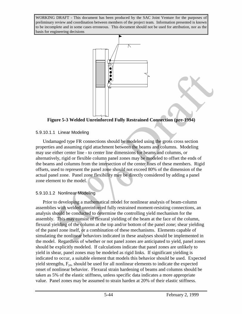
WORKING DRAFT - This document has been produced by the SAC Joint Venture for the purposes ofpreliminary review and coordination between members of the project team. Information presented is knownto be incomplete and in some cases erroneous. This document should not be used for attribution, nor as thebasis for engineering decisions
5-44 February 2, 1999
Figure 5-3 Welded Unreinforced Fully Restrained Connection (pre-1994)
5.9.10.1.1 Linear Modeling
Undamaged type FR connections should be modeled using the gross cross sectionproperties and assuming rigid attachment between the beams and columns. Modelingmay use either center line - to center line dimensions for beams and columns, oralternatively, rigid or flexible column panel zones may be modeled to offset the ends ofthe beams and columns from the intersection of the center lines of these members. Rigidoffsets, used to represent the panel zone should not exceed 80% of the dimension of theactual panel zone. Panel zone flexibility may be directly considered by adding a panelzone element to the model.
5.9.10.1.2 Nonlinear Modeling
Prior to developing a mathematical model for nonlinear analysis of beam-columnassemblies with welded unreinforced fully restrained moment-resisting connections, ananalysis should be conducted to determine the controlling yield mechanism for theassembly. This may consist of flexural yielding of the beam at the face of the column,flexural yielding of the column at the top and/or bottom of the panel zone; shear yieldingof the panel zone itself, or a combination of these mechanisms. Elements capable ofsimulating the nonlinear behaviors indicated in these analyses should be implemented inthe model. Regardless of whether or not panel zones are anticipated to yield, panel zonesshould be explicitly modeled. If calculations indicate that panel zones are unlikely toyield in shear, panel zones may be modeled as rigid links. If significant yielding isindicated to occur, a suitable element that models this behavior should be used. Expectedyield strengths, Fye, should be used for all nonlinear elements to indicate the expectedonset of nonlinear behavior. Flexural strain hardening of beams and columns should betaken as 5% of the elastic stiffness, unless specific data indicates a more appropriatevalue. Panel zones may be assumed to strain harden at 20% of their elastic stiffness.

WORKING DRAFT - This document has been produced by the SAC Joint Venture for the purposes ofpreliminary review and coordination between members of the project team. Information presented is knownto be incomplete and in some cases erroneous. This document should not be used for attribution, nor as thebasis for engineering decisions
5-45 February 2, 1999
5.9.10.2 Simple Shear Tab Connections - with slabs
This section presents modeling guidelines for the typical single plate shear tabconnection commonly used to connect beams to columns for gravity loads, whenmoment-resistance is not required by the design, and when concrete slabs are present.Figure 5-4 presents a detail for this connection. It is characterized by rolled wide flangebeams connected to either the major or minor axis of wide flange column sections. Beamwebs are connected to the column with a single plate shear tab, welded to the column andbolted to the beam web. A concrete floor slab, or slab on metal deck is present at the topflange of the beam.
Major Axis of Column Minor Axis of Column
Figure 5-4 Typical Simple Shear Tab Connection with Slab
5.9.10.2.1 Modeling Guidelines - Linear Analysis
One of the following two approaches shall be used to model framing with shear tabconnections when slabs are present:
a) Beams and columns connected with shear tabs shall be modeled using theirfull gross cross section properties. Connections of beams to columns shall beassumed to be pins.
b) Beams connected to columns shall be modeled using 5% of their grossmoment of inertia, while columns shall be modeled using the full cross sectionproperties. Framing shall be modeled center line to center line. Beam columnconnections shall be assumed to be fully rigid.
Commentary: The presence of gravity framing, utilizing shear tabconnectors, can provide substantial sitffening to WSMF system providedas the basic lateral force resisting system. The primary contributor to thisadded stiffness is the fact that the gravity load columns are constrained to
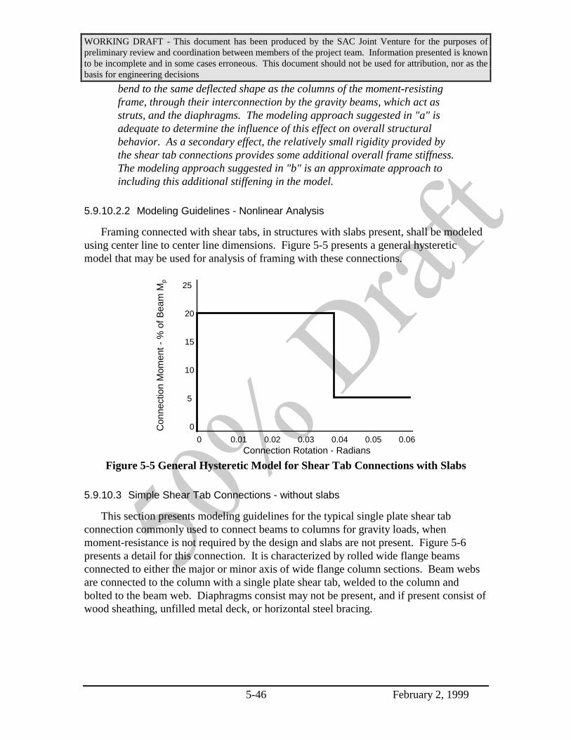
WORKING DRAFT - This document has been produced by the SAC Joint Venture for the purposes ofpreliminary review and coordination between members of the project team. Information presented is knownto be incomplete and in some cases erroneous. This document should not be used for attribution, nor as thebasis for engineering decisions
5-46 February 2, 1999
bend to the same deflected shape as the columns of the moment-resistingframe, through their interconnection by the gravity beams, which act asstruts, and the diaphragms. The modeling approach suggested in "a" isadequate to determine the influence of this effect on overall structuralbehavior. As a secondary effect, the relatively small rigidity provided bythe shear tab connections provides some additional overall frame stiffness.The modeling approach suggested in "b" is an approximate approach toincluding this additional stiffening in the model.
5.9.10.2.2 Modeling Guidelines - Nonlinear Analysis
Framing connected with shear tabs, in structures with slabs present, shall be modeledusing center line to center line dimensions. Figure 5-5 presents a general hystereticmodel that may be used for analysis of framing with these connections.
Con
nect
ion
Mom
ent -
% o
f Bea
m M
p
Connection Rotation - Radians0 0.01 0.02 0.03 0.04 0.05 0.06
25
20
15
10
5
0
Figure 5-5 General Hysteretic Model for Shear Tab Connections with Slabs
5.9.10.3 Simple Shear Tab Connections - without slabs
This section presents modeling guidelines for the typical single plate shear tabconnection commonly used to connect beams to columns for gravity loads, whenmoment-resistance is not required by the design and slabs are not present. Figure 5-6presents a detail for this connection. It is characterized by rolled wide flange beamsconnected to either the major or minor axis of wide flange column sections. Beam websare connected to the column with a single plate shear tab, welded to the column andbolted to the beam web. Diaphragms consist may not be present, and if present consist ofwood sheathing, unfilled metal deck, or horizontal steel bracing.

WORKING DRAFT - This document has been produced by the SAC Joint Venture for the purposes ofpreliminary review and coordination between members of the project team. Information presented is knownto be incomplete and in some cases erroneous. This document should not be used for attribution, nor as thebasis for engineering decisions
5-47 February 2, 1999
Major Axis of Column Minor Axis of Column
Figure 5-6 Typical Simple Shear Tab Connection without Slab
Commentary: Shear tabs of the type shown in Figure 5-6, though not aseffective in resisting frame lateral drifts as are shear tab connectionswhen slabs are present, as discussed in the previous section, do still havethe effect of coupling the deflected shapes of gravity columns to those ofcolumns intended to participate in the lateral-force-resisting system. Theconnections themselves, have negligible stiffness.
5.9.10.3.1 Modeling Guidelines - Linear Analysis
Beams and columns connected with shear tabs shall be modeled using their full grosscross section properties. Connections of beams to columns shall be assumed to be pins.
Commentary: The presence of gravity framing, utilizing shear tabconnectors, can provide substantial sitffening to WSMF system providedas the basic lateral force resisting system. The primary contributor to thisadded stiffness is the fact that the gravity load columns are constrained tobend to the same deflected shape as the columns of the moment-resistingframe, through their interconnection by the gravity beams, which act asstruts. The modeling approach suggested in this section is adequate todetermine the influence of this effect on overall structural behavior.
5.9.10.3.2 Modeling Guidelines - Nonlinear Analysis
Framing connected with shear tabs, in structures without slabs present, shall beincluding in the analytical model. Framing should be modeled using center line to centerline dimensions. Framing may be assumed to be pin connected, or alternatively, beamsconnected to columns with shear tab connections may be assigned 5% of their actualmoment of inertia.

WORKING DRAFT - This document has been produced by the SAC Joint Venture for the purposes ofpreliminary review and coordination between members of the project team. Information presented is knownto be incomplete and in some cases erroneous. This document should not be used for attribution, nor as thebasis for engineering decisions
5-48 February 2, 1999
5.9.11 Damage Modeling
This section presents guidelines for modeling various conditions of damage. Ingeneral, damage results in anisotropic frame behavior with affected framing exhibitingdifferent hysteretic properties for loading in a positive direction, than it does for loadingin the reverse direction. Except for nonlinear dynamic analyses, it is generally necessaryto utilize multiple models to represent these different behaviors, with loading applied inan appropriate direction for each model.
5.9.11.1 Type FR Connection Damage
Damaged type FR connections should be modeled in accordance with the guidelinesof this section. Refer to Chapter 5 for detailed descriptions of the various damageconditions.
a. Connections with any one of type G3, G4, G7, C2, C4, C5, W2, W3, W4, P5, orP6 damage at the bottom flange only may be modeled as undamaged for loadingconditions in which lateral loading will tend to place the fractured surfaces intocompression. For loading conditions in which the fracture is placed into tension,the connection shall be modeled as an undamaged simple shear tab connectionwith slab, per section 5.9.10.2.
b. Connections with any one of type G3, G4, G7, C2, C4, C5, W2, W3, W4, P5, orP6 damage at the top flange only may be modeled as undamaged for loadingconditions in which lateral loading will tend to place the fractured surfaces intocompression. For loading conditions in which the fracture is placed into tension,the connection shall be modeled as an undamaged simple shear tab connectionwithout slab, per section 5.9.10.3.
c. Connections with any combination of type G3, G4, G7, C2, C4, C5, W2, W3, W4,P5, or P6 damage at the top and bottom flanges shall be modeled as anundamaged simple shear tab connection with slab, per Section 5.9.10.2 forloading conditions in which the fracture at the beam bottom flange is placed intotension and shall be modeled as an undamaged simple shear tab connectionwithout slab, per Section 5.9.10.3 for loading conditions in which the fracture atthe top flange is placed into tension.
d. If any of the conditions in a, b, or c above is present in combination with shear tabdamage, types S1, S2, S3, S4, S5, or S6; the connection shall be modeled as anundamaged simple shear tab connection without slab, per Section 5.9.10.3 forboth directions of loading.
e. Connections with type P7 damage shall be modeled as follows. The beam andcolumn above the diagonal plane formed by the fracture shall be assumed to berigidly restrained to each other. The beam and column below the diagonal plane
WORKING DRAFT - This document has been produced by the SAC Joint Venture for the purposes ofpreliminary review and coordination between members of the project team. Information presented is knownto be incomplete and in some cases erroneous. This document should not be used for attribution, nor as thebasis for engineering decisions
5-49 February 2, 1999
formed by the fracture shall similarly be assumed to be rigidly restrained to eachother. The two assemblies consisting of the rigidly restrained beam-column jointabove and below the diagonal fracture shall be assumed to be unconnected forloading that places the fracture into tension and shall be assumed to be connectedto each other with a “pin” for conditions of loading that place the fracture intocompression.
f. Connections with type P9 damage and oriented as indicated in Figure 5-7 shall bemodeled with the beams and columns below the fracture surface assumed to berigidly connected. The column above the fracture surface shall be assumed to beunconnected for loading that places the column into tension and shall be assumedto be “pin” connected for loading that places the column into compression. If theorientation of type P9 damage is opposite that shown in Figure 5-7, then theinstructions for “top” and “bottom” columns above should be reversed.
5.9.11.2 Column Damage
a. If a column has type C1 or C3 damage in any flange, the column shall be modeledas if having a pinned connection (unrestrained for rotation) at that location forloading conditions that induce tension across the fracture. The column may bemodeled as undamaged for loading conditions that produce compression acrossthe fracture surfaces.
b. If a column has type C7, column splice fracture damage, it shall be assumed to beunconnected across the splice for load conditions that place the column in tensionand shall be assumed to have a “pin” connection for load conditions that place thecolumn in compression.
c. If a column has type C6, buckling damage of a flange, the buckled length of thecolumn shall be modeled with a separate element with flexural propertiescalculated using only 30% of the section of the buckled element.
5.9.11.3 Beam Damage
a. Beams that have lateral torsional buckling, type G8, should be modeled with aflexural pin at the center of the buckled region.
b. Beams that have type G1, buckling damage of a flange shall be modeled with thethe buckled length of the beam having represented by a separate element withflexural properties calculated using only 30% of the section of the buckled flange.
5.9.11.4 Other Damage
Damage other than indicated in Sections 5.9.11.1, 5.9.11.2, or 5.9.11.3 need not bemodeled unless in the judgment of the engineer, it results in significant alteration of the

WORKING DRAFT - This document has been produced by the SAC Joint Venture for the purposes ofpreliminary review and coordination between members of the project team. Information presented is knownto be incomplete and in some cases erroneous. This document should not be used for attribution, nor as thebasis for engineering decisions
5-50 February 2, 1999
stiffness or load distribution at the connection. In such cases, the engineer shall usedjudgment in developing the model such that it accurately reflects the behavior of thedamaged element(s).
5.10 Acceptance Criteria and Confidence Evaluation
The confidence provided with regard to the damaged building’s ability to resistcollapse under the levels of ground shaking likely in the immediate post-earthquakeperiod shall be determined through evaluation of the relationship:
γφλcon
C
D= (5-20)
where: φ = capacity reduction factorC = capacityλ = load factorD = computed demand
for each of the performance parameters indicated in Table 5-9. The value of γcon
determined for each of these performance parameters shall be used to determine a level ofconfidence associated with achieving the desired performance, either by reference toTable 5-10, or through direct calculation of confidence level through the procedures ofSection 5.11. The lowest of the confidence levels obtained for the structure for each ofthe design parameters shall establish the overall confidence with regard to the structure’sability to achieve the desired performance.
Table 5-9 Performance Parameters Requiring Evaluation of Confidence
Parameter Discussion
Inter-story Drift The maximum inter-story drift computed for any story of thestructure shall be evaluated. Refer to Section 5.10.1
Column Axial Load The adequacy of each column to withstand the calculatedmaximum compressive load for that column shall be evaluated.Refer to Section 5.10.2
Column SpliceTension
The adequacy of column splices to withstand calculatedmaximum tensile demands for the column shall be evaluated.Refer to Section 5.10.3
Beam-columnConnections
The adequacy of individual beam-column connections towithstand induced inter-story drift demands shall be evaluated.Refer to Section 5.10.4

WORKING DRAFT - This document has been produced by the SAC Joint Venture for the purposes ofpreliminary review and coordination between members of the project team. Information presented is knownto be incomplete and in some cases erroneous. This document should not be used for attribution, nor as thebasis for engineering decisions
5-51 February 2, 1999
Table 5-10 Confidence Level as a Function of the Parameter γcon
Confidence Level - % 50 65 84 90 95
Linear Static .2 .5 1 1.2 1.5
Linear Dynamic .3 .6 1.1 1.3 1.5
Nonlinear Static .4 .7 1.1 1.3 1.5
Nonlinear Dynamic .5 .8 1.2 1.3 1.5
Commentary: The process of predicting performance for a structureinherently incorporates a significant degree of uncertainty. Thisuncertainty may be ascribed to a number of factors including inaccuraciesin our modeling and analysis approaches, our lack of knowledge withregard to the construction quality, strength and damping inherent in thebuilding; inability to precisely predict the amount of dead and live loadpresent and other similar factors. In addition, the precise character of theground motion that will affect the structure and the capacity of thestructure to resist the resulting response can not be precisely predicted,nor do we completely understand the factors that affect the apparentvariation in these parameters.
Even though it is not possible to precisely predict all of theseparameters, it is possible to estimate bounds for each of these, to developan understanding of the effect of these uncertain and apparently randomparameters on the behavior and performance of the structure, and toestimate probabilistic distributions of the likely performance of thestructure, considering these bounds, using methods of structuralreliability.
The load factors, λ, and capacity reduction factors, φ, have beencalculated by assuming that the effects of these random and uncertainparameters result in a log normal distribution of response (inter-storydrift, member forces) and capacity. The standard deviations for thesedistributions have been estimated based on statistical distributions of dataobtained from laboratory testing of typical beam-column assemblies,analytical evaluations of building structures, and by judgment.
The load factors, λ, include a component that accounts for thestatistical distribution of response, given the distribution of random anduncertain response, as well as the bias inherent in the analytical techniqueused to predict the response parameters. The resistance factors, φ,account for the variation and uncertainty inherent in the prediction of

WORKING DRAFT - This document has been produced by the SAC Joint Venture for the purposes ofpreliminary review and coordination between members of the project team. Information presented is knownto be incomplete and in some cases erroneous. This document should not be used for attribution, nor as thebasis for engineering decisions
5-52 February 2, 1999
capacity. When the factored demand, λD is exactly equal to the factoredcapacity, φC, then this indicates that given the level of knowledgeavailable with regard to the behavior of the building, there is mean levelof confidence that the building will meet the performance being analyzed,in the case of post-earthquake assessments, a state of incipient collapse.
If greater knowledge can be obtained with regard to the probablebehavior of the building, for example through performing more rigorousquality assurance during construction or by performing more rigorousand accurate analytical evaluations of the building, then the uncertaintyassociated with both the prediction of the building’s response and theability of the building to withstand this response without exceeding thespecific performance goal, is reduced. This reduction in uncertainty canbe expressed as a reduction in the standard deviations of the distributionof possible response and capacity states of the building. As theuncertainty in response prediction is reduced, for example through the useof more accurate modeling and analytical methods, the load factorsassociated with the prediction of mean values of response parameters atthe desired probability of exceedance may be reduced. Thus, as reflectedin Table 5-4, the load factors associated with nonlinear analysisapproaches are generally lower than those associated with the linearapproaches.
As used in these Guidelines, confidence reflects the extent to which theuncertain parameters that affect performance prediction are understood.A high level of confidence is attained when there is a high level ofcertainty that the desired performance will be attained, while a low levelof confidence reflects a significant degree of uncertainty with regard tothe ability of the structure to provide the desired performance. The extentof certainty inherent in the performance prediction, and consequently thelevel of confidence associated with a building’s ability to provide specifiedperformance is indexed to the γcon parameter.
A calculated value of γcon of 1.0 indicates a mean level of confidence ofachieving the desired performance at the target annual probability ofexceedance. Since it is assumed that performance is log normallydistributed with regard to the uncertain parameters, a mean level ofconfidence is actually somewhat higher than a 50% certainty of being ableto achieve the desired performance, approximately on the order of 70%confidence. Values of γcon that exceed 1.0 indicate more certainperformance and values less than 1.0, less certain performance.
γcon is calculated as a function of the standard deviation of the log ofthe uncertain parameters and as a function of the hazard curve for the site

WORKING DRAFT - This document has been produced by the SAC Joint Venture for the purposes ofpreliminary review and coordination between members of the project team. Information presented is knownto be incomplete and in some cases erroneous. This document should not be used for attribution, nor as thebasis for engineering decisions
5-53 February 2, 1999
itself. The tabulated values of inter-story drift capacity, resistance factorsand confidence parameters contained in this section are based on thestudy of typical buildings, and the use of a presumed hazard function inthe immediate post-earthquake environment as described in Section 5.6.Section 5.11 presents a detailed procedure for calculating the capacity forinter-story drift for various performance levels, the resistance factorassociated with that capacity and the confidence parameter, γcon. Themore detailed procedures of Section 3.7 may be used, when warranted, toreduce the uncertainty inherent in performance prediction and potentiallyobtain more optimistic estimates of probable performance.
5.10.1 Interstory Drift Capacity - Global Stability
Factored inter-story drift capacity, φC, to maintain global stability shall be taken asthe product of the resistance factor φ and capacity C, obtained from Table 5-10. In lieu ofthe values contained in Table 5-10, the more detailed procedures of Section 5.11 may beused to determine inter-story drift capacity as limited by global building response.
Table 5-10 Inter-story Drift Capacity and as Limited By Global Response, andAssociated Resistance Factors
Structure Type Inter-storyDrift
Capacity
ResistanceFactor
φ
Low Rise -(3 above grade stories or less) .10 .6
Mid Rise - (4 or more above grade stories, butnot more than 12 above grade stories)
.08 .6
High Rise - More than 12 above grade stories .05 .6
5.10.2 Column Compressive Capacity
The capacity of each individual column to resist compressive axial loads shall bedetermined as the product of the resistance factor, φ, and the compressive strength of thecolumn as determined in accordance with the AISC Load and Resistance Factor DesignSpecification. For the purposes of this evaluation, φ shall be assigned a value of 0.7.
5.10.3 Column Splice Capacity
The capacity of individual column splices to resist tensile axial loads shall bedetermined as the product of the resistance factor, φ, and the tensile strength of the splice,as determined in accordance with the AISC Load and Resistance Factor Design
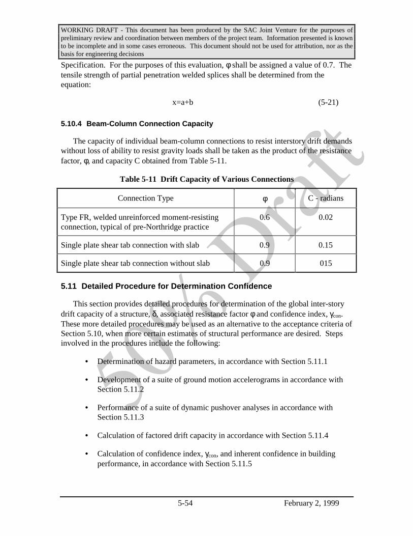
WORKING DRAFT - This document has been produced by the SAC Joint Venture for the purposes ofpreliminary review and coordination between members of the project team. Information presented is knownto be incomplete and in some cases erroneous. This document should not be used for attribution, nor as thebasis for engineering decisions
5-54 February 2, 1999
Specification. For the purposes of this evaluation, φ shall be assigned a value of 0.7. Thetensile strength of partial penetration welded splices shall be determined from theequation:
x=a+b (5-21)
5.10.4 Beam-Column Connection Capacity
The capacity of individual beam-column connections to resist interstory drift demandswithout loss of ability to resist gravity loads shall be taken as the product of the resistancefactor, φ, and capacity C obtained from Table 5-11.
Table 5-11 Drift Capacity of Various Connections
Connection Type φ C - radians
Type FR, welded unreinforced moment-resistingconnection, typical of pre-Northridge practice
0.6 0.02
Single plate shear tab connection with slab 0.9 0.15
Single plate shear tab connection without slab 0.9 015
5.11 Detailed Procedure for Determination Confidence
This section provides detailed procedures for determination of the global inter-storydrift capacity of a structure, δ, associated resistance factor φ and confidence index, γcon.These more detailed procedures may be used as an alternative to the acceptance criteria ofSection 5.10, when more certain estimates of structural performance are desired. Stepsinvolved in the procedures include the following:
• Determination of hazard parameters, in accordance with Section 5.11.1
• Development of a suite of ground motion accelerograms in accordance withSection 5.11.2
• Performance of a suite of dynamic pushover analyses in accordance withSection 5.11.3
• Calculation of factored drift capacity in accordance with Section 5.11.4
• Calculation of confidence index, γcon, and inherent confidence in buildingperformance, in accordance with Section 5.11.5

WORKING DRAFT - This document has been produced by the SAC Joint Venture for the purposes ofpreliminary review and coordination between members of the project team. Information presented is knownto be incomplete and in some cases erroneous. This document should not be used for attribution, nor as thebasis for engineering decisions
5-55 February 2, 1999
5.11.1 Hazard Parameters
A 5% damped, elastic response spectrum for the ground shaking that caused the initialdamage, at the fundamental period of the damaged structure shall be estimated inaccordance with the guidelines of Section 5.7.2.
5.11.2 Ground Motion Accelerograms
A suite of at least 10 ground motion accelerograms shall be developed that arecompatible with the 5% damped response spectrum for the site, determined in accordancewith Section 5.11.1. The accelerograms shall be scaled to achieve spectral compatibilityin accordance with the guidelines of FEMA-273.
5.11.3 Dynamic Pushover Analysis
A nonlinear mathematical model of the damaged building shall be constructed, inaccordeance with the modeling rules of Section 5.9. The model shall realistically modelthe material and geometric nonlinearities that may occur in the structure under largelateral response, including P-∆ effects, panel zone flexibility, if significant, and hystereticbehavior of beam-column connections. The stiffness of beam-column frames, notintended to participate in lateral force resistance shall also be included in the model.Equivalent viscous damping shall be taken as 3%.
For each ground motion, developed in accordance with Section 5.11.3, a dynamicpushover analysis shall be conducted, using the following procedure:
1. The ground motion shall be scaled to an index, spectral response accelerationat the fundamental period of the structure, that produces elastic response.
2. A response history analysis of the structure, for response to this ground motionshall be performed. The maximum inter-story drift obtained from the analysisshall be recorded.
3. The amplitude of the ground motion used in the analysis of step 2 shall bescaled to 110% of the amplitude used in that analysis.
4. Steps 2 and 3 shall be repeated, with the maximum inter-story drift predictedby each successive analysis recorded, until either the structure is predicted tocollapse by the analysis or maximum inter-story drift predicted by the analysisexceeds 10%.
5. A plot of the index spectral response acceleration at the structure’sfundamental period for each of the analyses and the maximum interstory driftobtained from the analysis shall be created. Such a plot, illustrated in Figure5-7, is termed a dynamic pushover plot.

WORKING DRAFT - This document has been produced by the SAC Joint Venture for the purposes ofpreliminary review and coordination between members of the project team. Information presented is knownto be incomplete and in some cases erroneous. This document should not be used for attribution, nor as thebasis for engineering decisions
5-56 February 2, 1999
Maximum Interstory Drift
Spe
ctra
l Res
opns
e A
ccel
erat
ion
- S
a
0 0.01 0.02 0.03 0.04 0.05 0.06
2.0
1.5
1.0
0.5
0
Predicted drift capacity
Peak spectral accelerationcapacity
K1 0.8 K
1
Figure 5-7 Dynamic Pushover Curve
6. The slope of the initial portion of the dynamic pushover plot shall be noted. Aline shall be constructed from the origin of the dynamic pushover plot andhaving a slope of 80% of the slope of the initial portion of the dynamicpushover plot. The inter-story drift at the intersection of this line, having 80%of the slope of the initial portion of the curve, and the pushover curve itself,shall be taken as the inter-story drift capacity of the structure, for this groundmotion. Refer to Figure 5-7. The inter-story drift capacity shall not be takenas greater than 0.1.
5.11.4 Determination of Factored Interstory Drift Capacity
The inter-story drift capacities δi, determined from each of the dynamic pushoveranalyses shall be tabulated, together with the natural logarithm of these inter-story driftcapacities, ln(δi). The median value of the δi statistics shall be determined, as shall thestandard deviation, σlnδ of the natural logarithms of the inter-story drift capacities. Aresistance factor, φ, shall be determined from the equation:
φσ δ
=−
ek
bln
2
2(5-22)
where: k = the slope of the hazard curve, plotted in ln-ln coordinates, during theimmediate post-earthquake period, which may be taken as having a valueof 4.0
b = a hazard parameter that may be taken as having a value of 1.0
σlnδ = the standard deviation of the natural logarithms of the predicted inter- story drifts obtained from the pushover anlayses
Factored inter-story drift demand for global response shall be taken as the product ofφ determined in accordance with equation 5-22 and the median inter-story drift capacity

WORKING DRAFT - This document has been produced by the SAC Joint Venture for the purposes ofpreliminary review and coordination between members of the project team. Information presented is knownto be incomplete and in some cases erroneous. This document should not be used for attribution, nor as thebasis for engineering decisions
5-57 February 2, 1999
determined from the dynamic pushover analyses.
5.11.5 Determination of Confidence Level
A performance confidence index, γcon, shall be determined in accordance with Section5.10, for each of the controlling performance parameters indicated in Table 5-9. Theconfidence parameter Kx, shall be determined from the equation, using the smallest of thevalues γcon:
Kb
kx
con
UT
UT= +ln( )γ
σσ2
(5-23)
where: k, and b are the hazard parameters defined in Section 5.11.4.σUT = is a measure of the uncertainty related to prediction of drift demand, taken fromTable 5-12.
Table 5-12 Uncertainty Measures for Different Analytical Procedures
Analytical Procedure σUT
Linear Static Procedure 0.6
Linear Dynamic Procedure 0.7
Nonlinear Static Procedure 0.8
Nonlinear Dynamic Procedure 0.9
The level of confidence with regard to the target performance shall be determined byinterpolation from, Table 5-13.
Table 5-13 - Values of Kx for Various Levels of Confidence
Confidence Level KX
65% 0
84% 1
90% 1.3
95% 1.6

WORKING DRAFT - This document has been produced by the SAC Joint Venture for the purposes ofpreliminary review and coordination between members of the project team. Information presented is knownto be incomplete and in some cases erroneous. This document should not be used for attribution, nor as thebasis for engineering decisions
5-58 February 2, 1999
5.12 Evaluation Report
Regardless of the level of evaluation performed, the responsible structural engineershould prepare a written evaluation report and submit it to the owner upon completion ofthe evaluation. When the building official has required evaluation of a WSMF building,this report should also be submitted to the building official. This report should directly,or by attached references, document the inspection program that was performed, andprovide an interpretation of the results of the inspection program and a generalrecommendation as to appropriate repair and occupancy strategies. The report shouldinclude but not be limited to the following material:
• Building Address
• A narrative description of the building, indicating plan dimensions, number ofstories, total square feet, occupancy, the type and location of lateral-force-resistingelements. Include a description of the grade of steel specified for beams andcolumns and, if known, the type of welding (SMAW, FCAW, etc.) present.Indicate if moment connections are provided with continuity plates. The narrativedescription should be supplemented with sketches (plans and evaluations) asnecessary to provide a clear understanding of pertinent details of the building’sconstruction. The description should include an indication of any structuralirregularities as defined in the Building Code.
• A description of nonstructural damage observed in the building.
• An estimate of the ground shaking intensity experienced by the building,determined in accordance with Section 5.7.
• A description of the inspection and evaluation procedures used, includingdocumentation of all instructions to the inspectors, and of the signed inspectionforms for each individual inspected connection.
• A description, including engineering sketches, of the observed damage to thestructure as a whole (e.g., permanent drift) as well as at each connection, keyed tothe damage types in Chapter 5, photographs should be included for all connectionswith significant visible damage.
• Calculations demonstrating the determination of a confidence level with regard tothe building’s ability to resist collapse in the immediate post-earthquake period.
• A summary of the recommended actions (repair and modification measures andoccupancy restrictions).
The report should include identification of any potentially hazardous conditionswhich were observed, including corrosion, deterioration, earthquake damage, pre-existing

WORKING DRAFT - This document has been produced by the SAC Joint Venture for the purposes ofpreliminary review and coordination between members of the project team. Information presented is knownto be incomplete and in some cases erroneous. This document should not be used for attribution, nor as thebasis for engineering decisions
5-59 February 2, 1999
rejectable conditions, and evidence of poor workmanship or deviations from the approveddrawings. In addition, the report should include an assessment of the potential impacts ofobserved conditions on future structural performance. The report should include the FieldInspection Reports of damaged connections, as an attachment, and should bear the seal ofthe structural engineer in charge of the evaluation.
Commentary: Following completion of the detailed damage assessments,the structural engineer should prepare a written report. The report shouldinclude identification of any potentially hazardous conditions which wereobserved, including earthquake damage, pre-existing rejectableconditions, and evidence of poor workmanship or deviations from theapproved drawings. In addition, the report should include an assessmentof the potential impacts of observed conditions on future structuralperformance. The report should include the field inspection, visualinspection and NDT records, data sheets, and reports as attachments.
The nature and scope of the evaluations performed should be clearlystated. If the scope of evaluation does not permit an informed judgment tobe made as to the extent with which the building complies with theapplicable building codes, or as to a statistical level of confidence that thedamage has not exceeded an acceptable damage threshold, this should bestated.
5.13 Qualified Independent Engineering Review
Independent third party review, by qualified professionals, is recommendedthroughout these Guidelines when alternative approaches to evaluation or design aretaken, or where approaches requiring high degrees of structural engineering knowledgeand judgment are taken. Specifically, it is recommended that qualified engineering reviewbe provided where:
• the level of confidence that the building can resist collapse is less than 50% andthe engineer has determined that an unsafe condition does not exist.
• Where an engineer has decided not to repair damage otherwise recommended tobe repaired by these Guidelines.
• When any story of the building has experienced a permanent lateral driftexceeding 1% of the story height and proposed repairs do not correct thiscondition.
• When nonlinear dynamic analyses are performed as part of the evaluation.
Where independent review is recommended, the analysis and/or design should besubjected to an independent and objective technical review by a knowledgeable reviewer

WORKING DRAFT - This document has been produced by the SAC Joint Venture for the purposes ofpreliminary review and coordination between members of the project team. Information presented is knownto be incomplete and in some cases erroneous. This document should not be used for attribution, nor as thebasis for engineering decisions
5-60 February 2, 1999
experienced in the design, analysis, and structural performance issues involved. Thereviewer should examine the available information on the condition of the building, thebasic engineering and reliability concepts, and the recommendations for proposed action.
Commentary: The independent reviewer may be one or more personswhose collective experience spans the technical issues anticipated in thework. When more than one person is collectively performing theindependent review, one of these should be designated the review chairand should act on behalf of the team in presenting conclusions orrecommendations.
Independent third party review is not a substitute for plan checking. Itis intended to provide the structural engineer of record with anindependent opinion, by a qualified expert, on the adequacy of structuralengineering decisions and approaches. The seismic behavior of WSMFstructures is now understood to be an extremely complex issue. Properunderstanding of the problem requires knowledge of structural mechanics,metallurgy, welding, fracture mechanics, earthquake engineering, andstatistics. Due to our limited current state of knowledge, evenprofessionals who possess such knowledge face considerable uncertaintyin making design judgments. Third party review should only be performedby qualified individuals.
5.13.1 Timing of Independent Review
The independent reviewer(s) should be selected prior to the initiation of substantialportions of the design and/or analysis work that is to be reviewed, and coordination of thereview should start as soon as sufficient information to define the project is available.
5.13.2 Qualifications and Terms of Employment
The reviewer should have no other involvement in the project before, during, or afterthe review. The reviewer should be selected and paid by the owner and should have anequal or higher level of technical expertise in the issues involved than the structuralengineer-of-record. The reviewer (or in the case of peer review teams, the review chair)should be a structural engineer who is familiar with governing regulations for the workbeing reviewed. The reviewer should serve through completion of the project and shouldnot be terminated except for failure to perform the duties specified herein. Suchtermination should be in writing with copies delivered to the building official, owner, andstructural engineer-of-record.

WORKING DRAFT - This document has been produced by the SAC Joint Venture for the purposes ofpreliminary review and coordination between members of the project team. Information presented is knownto be incomplete and in some cases erroneous. This document should not be used for attribution, nor as thebasis for engineering decisions
5-61 February 2, 1999
5.13.3 Scope of Review
Review activities related to evaluation of the safety condition of a building shouldinclude a review of available construction documents for the building, all inspection andtesting reports, any analyses prepared by the structural engineer of record, the method ofconnection sample selection, and visual observation of the condition of the structure, aswell as review of any mathematical models and analyses performed as part of the post-earthquake evaluation. Review should include consideration of the proposed designapproach, methods, materials, and details.
5.13.4 Reports
The reviewer should prepare a written report to the owner and building official thatcovers all aspects of the structural engineering review performed, including conclusionsreached by the reviewer. Such reports should include statements on the following:
• Scope of engineering review performed with limitations defined.
• The status of the project documents at each review stage.
• Ability of selected materials and framing systems to meet performance criteriawith given loads and configuration.
• Degree of structural system redundancy, ductility, and compatibility, particularlyin relation to lateral forces.
• Basic constructability of structural members and connections (or repairs andmodifications of these elements).
• Other recommendations that would be appropriate to the specific project.
• Presentation of the conclusions of the reviewer identifying any areas which needfurther review, investigation, and/or clarifications.
5.13.5 Responses and Corrective Actions
The structural engineer-of-record should review the report from the reviewer anddevelop corrective actions and other responses as appropriate. Changes during theconstruction/field phases that affect the seismic resistance system should be reported tothe reviewer in writing for action and recommendations.
5.13.6 Distribution of Reports
All reports, responses, and corrective actions prepared pursuant to this section shouldbe submitted to the building official and the owner along with other plans, specifications,

WORKING DRAFT - This document has been produced by the SAC Joint Venture for the purposes ofpreliminary review and coordination between members of the project team. Information presented is knownto be incomplete and in some cases erroneous. This document should not be used for attribution, nor as thebasis for engineering decisions
5-62 February 2, 1999
and calculations required. If the reviewer is terminated by the owner prior to completionof the project, then all reports prepared by the reviewer, prior to such termination, shouldbe submitted to the building official, the owner, and the structural engineer-of-recordwithin ten (10) working days of such termination.
5.13.7 Engineer-of-Record
The structural engineer-of-record should retain the full responsibility for the structuraldesign as outlined in professional practice laws and regulations. The independent reviewengineer(s) should not be asked to or be expected to assume any responsibility for thestructural evaluation or subsequent repair designs.
5.13.8 Resolution of Differences
If the structural engineer-of-record does not agree with the recommendations of thereviewer, then such differences should be resolved by the building official in the mannerspecified in the applicable Building Code.

WORKING DRAFT - This document has been produced by the SAC Joint Venture for the purposes of preliminaryreview and coordination between members of the project team. Information presented is known to be incompleteand in some cases erroneous. This document should not be used for attribution, nor as the basis for engineeringdecisions
6-1 02/02/991
6. POST-EARTHQUAKE REPAIR
6.1 Scope
This section provides criteria for structural repair of earthquake damage. Repair constitutesany measure(s) taken to restore earthquake damaged elements of the building, includingindividual members or their connections, or the building as whole, to their original configuration,strength, stiffness and deformation capacity. It does not include routine correction of non-conforming conditions resulting from the original fabrication or upgrades intended to result inimprovement in future seismic performance of the building.
Guidelines for acceptable methods of repair are provided in Sections 6.2 through 6.3 below.These Guidelines are not intended to be used for the routine repair of construction non-conformance commonly encountered in fabrication and erection work. Industry standardpractices are acceptable for such repairs. Guidelines for assessment of the seismic performancecapability of existing buildings and upgrade of building to improve performance capability maybe found in a companion publication, FEMA-XXX Evaluation and Upgrade Criteria for WeldedSteel Moment-Resisting Structures.
Commentary: Based on the observed behavior of actual buildings in theNorthridge Earthquake, as well as recent test data, WSMF structures constructedwith the typical detailing and construction practice prevalent prior to1994 do nothave the same deformation capacity they were presumed to possess at the time oftheir design and therefore present significantly higher risks than was originallythought. When these buildings are damaged or have excessive constructiondefects, this risk is higher still.
Based on (limited) testing, it is believed that the repair recommendationscontained in these Guidelines can be effective in restoring a building’s pre-earthquake condition, and to the extent that workmanship and materials of repairwork is improved relative to the original construction, provide some marginalimprovement in seismic performance capability. This does not imply, however,that the repaired building will be an acceptable seismic risk. As a minimum, itshould be assumed that buildings that are repaired, but not upgraded, can sustainsimilar and possibly more severe damage in future earthquakes than they did inthe present event. If this is unacceptable, either to the owner or the buildingofficial, then the building should be upgraded to provide improved futureperformance. Retrofit can consist of local reinforcement of individual momentconnections as well as alteration of the basic lateral-force-resistingcharacteristics of the structure through addition of braced frames, shear walls,base isolation, energy dissipation devices, etc. Performance evaluation andstructural retrofit are beyond the scope of these Guidelines. Criteria forperformance evaluation and structural retrofit may be found in a companion

WORKING DRAFT - This document has been produced by the SAC Joint Venture for the purposes of preliminaryreview and coordination between members of the project team. Information presented is known to be incompleteand in some cases erroneous. This document should not be used for attribution, nor as the basis for engineeringdecisions
6-2 02/02/992
document, Upgrade and Evaluation Criteria for Existing Welded Steel MomentFrame Structures, FEMA-XXX.
6.2 Shoring and Temporary Bracing
6.2.1 Investigation
Prior to engaging in repair activity, the structural engineer should investigate the entirebuilding and perform an evaluation to if any imminent collapse or life safety hazard conditionsexist and to determine if the structure as a whole provides adequate stability to safeguard lifeduring the repair process. The level 2 evaluation process, of Chapter 4 is one method ofconfirming the building’s global structural stability. Where hazardous conditions or lack ofstability are detected, shoring and or temporary bracing should be provided prior tocommencement of any repairs.
Commentary: In projects relating to construction of new buildings, it is commonpractice to delegate all responsibility for temporary shoring and bracing of thestructure to the contractor. Such practice may not be appropriate for severelydamaged buildings. The structural engineer should work closely with thecontractor to define shoring and bracing requirements. Some structuralengineers may wish to perform the design of temporary bracing systems. If thecontractor performs such design, the structural engineer should review thedesigns for adequacy and potential effects on the structure prior toimplementation.
6.2.2 Special Requirements.
Conditions which may become collapse or life safety hazards during the repair operationsshould be considered in the development of repair details and specifications, whether theyinvolve the damage area directly or indirectly. These conditions should be brought to theattention of the contractor by the structural engineer, and adequate means of shoring theseconditions should be developed. Consideration should be given to sequencing of repairprocedures for proper design of any required shoring. For column repair details that requireremoval of 20% or more of the damaged cross section, consideration should be given to the needfor shoring to prevent overstress of elements due to redistribution of loads.
Commentary: In general, contractors will not have adequate resources to definewhen such shoring is necessary. Therefore, the Contract Documents shouldclearly indicate when and where shoring is required. Design of this shoring maybe provided by the structural engineer, or the contract documents may requirethat the contractor submit a shoring design to the structural engineer for review.

WORKING DRAFT - This document has been produced by the SAC Joint Venture for the purposes of preliminaryreview and coordination between members of the project team. Information presented is known to be incompleteand in some cases erroneous. This document should not be used for attribution, nor as the basis for engineeringdecisions
6-3 02/02/993
6.3 Repair Details
The scope of repair work should be shown on drawings and specifications prepared by astructural engineer. The drawings should clearly indicate the areas requiring repair, as well as allrepair procedures, details, and specifications necessary to properly implement the proposedrepair. Sample repair details for various types of damage are included in this design criteria, forreference, only.
Commentary: Examples of repair details are provided for some classes ofdamage, based on approaches successfully performed in the field following theNorthridge earthquake. Limited testing indicates these repair methods can beeffective. Details are not complete in all respects and should not be usedverbatim, as construction documents. Many repairs will require the applicationof more than one operation, as represented by a given detail. The sample detailsindicated may not be directly applicable to specific repair conditions. Thestructural engineer is cautioned to thoroughly review the conditions at eachdamaged element, connection or joint, and to determine the applicability andsuitability of these details based on sound structural engineering judgment, priorto employing them on projects.
In typical practice for construction of new buildings, the selection of meansand methods used to construct design details are typically left to the contractor.In structural repair work, the members are typically under greater load and alsorestraint than is common in new construction. Therefore, the typical constructionpractices may not be appropriate and many contractors may not have theknowledge or experience to select appropriate methods for repair work. As aresult, these guidelines suggest much greater specification of means and methodsthan is common in new construction. Although it is recommended that theengineer provide such specification as part of the construction documents, theengineers should also be open to suggestions for alternative procedures if thecontractor desires to submit such procedures. If there is doubt as to the ability ofalternative procedures to provide acceptable construction, a full-scale mock-uptest of the proposed procedure should be considered.
6.3.1 Approach
Based on the nature and extent of damage several alternative approaches to repair should beconsidered. Repair approaches may include, but should not be limited to:
a) replacement of damaged portions of base metal (i.e. column and beam section),
b) replacement of damaged connection elements,
c) replacement of connection welds, or

WORKING DRAFT - This document has been produced by the SAC Joint Venture for the purposes of preliminaryreview and coordination between members of the project team. Information presented is known to be incompleteand in some cases erroneous. This document should not be used for attribution, nor as the basis for engineeringdecisions
6-4 02/02/994
d) repairs to portions of any of the aforementioned components.
Any or all of these techniques may be appropriate. The approach(s) used should consideradjacent structural components that may be affected by the repair or the effects of the repair.
Where base material is to be removed and replaced with plates or shapes, clear directionshould be given to orient the new material with the direction of rolling parallel to the direction ofapplication of major axial loads to be resisted by the section.
6.3.2 Weld Fractures - Type W Damage
All fractures and rejectable defects found in weld material, either between girder and columnor between connection element and structural member, should have sufficient material removedto completely eliminate any discontinuity or defect. NDT should be used to determine the extentof fracture or defect and sufficient material should be removed to encompass the damaged area.It is suggested that material removal extend 2 inches beyond the apparent end of the fracture ordefect. Simple fillet welds may be repaired by backgouging to eliminate unsound weld materialand replacing the damaged weld with sound material. Complete joint penetration (CJP) weldsfractured through the full thickness should be replaced with sound material deposited in strictaccordance with the Welding Procedure Specification (WPS) and project specifications. Weldbacking, existing end dams, and weld tabs should be removed from all welds that are beingrepaired. End dams should not be permitted in new work. After backing and tab elements areremoved, the weld root should be backgouged to sound material, rewelded and a reinforcing filletadded.
The structural engineer is cautioned to observe the provisions of AISC regarding intermixingof weld metals deposited by different weld processes (see AISC LRFD Manual of SteelConstruction, second edition, page 6-77, and AISC ASD Steel Construction Manual, ninthedition, page 5-69). As an example, E7018 shielded metal arc welding (SMAW) stick electrodesshould not be used to weld over self-shielded flux cored arc welding (FCAW-S) deposits.Removed weld material from fractures not penetrating the full weld thickness should be replacedin the same manner as full thickness fractures. For other types of W damage, existing backing,end dams, and weld tabs should also be removed in a like manner to CJP weld replacement.Table 6-1 provides an index to suggested repair details for type W damage.
Table 6-1 - Reference Details for Type W Damage
Damage or Defect Class FigureRejectable defects at weld root Figure 6-1, Figure 6-2W2 Figure 6-3W3 Figure 6-3W4 Figure 6-3W5 Figure 6-3

WORKING DRAFT - This document has been produced by the SAC Joint Venture for the purposes of preliminaryreview and coordination between members of the project team. Information presented is known to be incompleteand in some cases erroneous. This document should not be used for attribution, nor as the basis for engineeringdecisions
6-5 02/02/995
20o Min.Arc - Gouge
1/4” radius min.
Existing column flange
Removed backing
Existing beam flange
Reweld & reinforcew/ fillet
Notes:
1 Remove existing backing.2 Taper the depth of grinding or air arc gouging at each end to the face of flange with a minimum 2:1
(horizontal/vertical) taper. Provide a minimum root radius of 1/4.î3 Grind all surfaces on which weld metal will be deposited. Surfaces should be smooth, uniform and free
from fins, tears, fractures and other discontinuities that would adversely affect weld strength.4 A fillet weld should be applied to reinforce the joint. The size of the reinforcing fillet should be equal to
1/4 of the beam flange thickness, but not less than 1/4. It need nor be more than 3/8.5 On joints to be repaired, remove all remaining weld tabs and excess weld metal beyond the length of the
joint and grind smooth. Imperfection less than 1/16" should be removed by grinding. Repair as necessary.
Figure 6-1 - Gouge & Re-weld of Root Defect or Damage
Existing column flange
Removed backing
Existing beam flange
Backgouge , repair andreinforce per Figure 6-1.
Air-arc gougeReweld
Notes:
1. Remove the entire fracture plus 1/8” of sound metal beyond each end.2. For additional notes, refer to Figure 5-1
Figure 6-2 - Gouge & Re-weld of Fractured Weld

WORKING DRAFT - This document has been produced by the SAC Joint Venture for the purposes of preliminaryreview and coordination between members of the project team. Information presented is known to be incompleteand in some cases erroneous. This document should not be used for attribution, nor as the basis for engineeringdecisions
6-6 02/02/996
Existing column flange
Existing beam flange
Remove backing aftercompleting top welding,Backgouge , repair andreinforce, per Figure 6-1.
Air-arc gougeReweld
For notes see Figure 6-1 and 6-2.
Figure 6-3 - Backgouge and Reweld repair
Commentary: FCAW-S utilizes approximately 1-2% aluminum in the electrode toprotect the weld from mixing with atmospheric nitrogen and oxygen. By itself,aluminum can reduce the toughness and ductility of weld metal. The design ofFCAW-S electrodes requires the balance of other alloys in the deposit tocompensate for the effects of aluminum. Other welding processes rely on fluxesand/or gasses to protect the weld metal from the atmosphere, relieving them ofany requirement to contain aluminum or other elements that offset the effects ofaluminum. If the original weld that is being repaired consists of FCAW-S andsubsequent repair welds are made with SMAW (stick) using E7018, for example,the SMAW arc will penetrate into the FCAW-S deposit, resulting in the addition ofsome aluminum into the SMAW deposit. The notch toughness and/or ductility ofthe resultant weld metal may be substantially reduced as compared to pure E7018weld metal, based on the depth of penetration into the FCAW-S material.
Various types of FCAW-S electrodes may be mixed one with the other withoutpotentially harmful effect. Further, FCAW-S may be used to weld over othertypes of weld deposits without potentially harmful interaction. The structuralengineer could specify all repairs on FCAW-S deposits be made with FCAW-S.Alternately, intermixing of FCAW-S and other processes could be permittedprovided the subsequent composition is demonstrated to meet materialspecification requirements.
The guidelines of Chapters 3, 4, and 5 for inspection and evaluation ofdamaged buildings do not require extensive nondestructive examination of weldsto detect defects or fractures that are not detectable by visual inspection but arerejectable under the AWS D1.1 provisions. Nevertheless, it is likely that in thecourse of performing inspection and repair work, some such rejectable conditionswill be found. It is recommended that any such detected conditions be repaired as

WORKING DRAFT - This document has been produced by the SAC Joint Venture for the purposes of preliminaryreview and coordination between members of the project team. Information presented is known to be incompleteand in some cases erroneous. This document should not be used for attribution, nor as the basis for engineeringdecisions
6-7 02/02/997
part of the overall building repair program, as their presence in welds make thewelds significantly more vulnerable to future fracturing under loading,particularly if the welds are composed of low toughness material.
In the past, there has been considerable disagreement as to whether or notsmall cracks and defects at the root of a weld are earthquake damage or not, asthis affects who may be responsible for costs related to the repair of suchconditions. Proper observation by knowledgable persons can reveal whether aroot defect is a slag inclusion or lack of fusion, both conditions relating to theoriginal construction, or an actual crack. It should be noted that cracks may notnecessarily be caused by the building’s earthquake response. Some crackinginvariably occurs in structures during the erection process as a result of residualstress conditions and thermal upset. It is almost impossible to distinguish suchcracks from those caused by an earthquake, except through detailed examinationof the fracture surface for evidence of oxidation or other signs of age. Manyresearchers believe that the low toughness weld metal commonly used inconstruction prior to 1994 was incapable of arresting an earthquake inducedfracture, once it initiated in a joint and that small cracks that do not penetratethrough the metal are unlikely to be earthquake related. However, there havebeen reports from laboratory testing that indicate that small cracks do form in theweld metal and arrest prior to development of unstable fracture conditions.Therefore, without detailed examination of an individual fracture byknowledgeable individuals, no conclusive statement can be made as to whetherweld cracking is earthquake induced.
6.3.3 Column fractures - Type C1 - C5 and P1 - P6
Any column fracture observable with the naked eye or found by NDT and classified asrejectable in accordance with the AWS D1.1 criteria for Static Structures should be repaired.Repairs should include removing the fracture such that no sign of rejectable discontinuity ordefect within a six (6) inch radius around the fracture remains. Removal should includeeliminating any zones of fracture propagation, with a minimum of heat used in the removalprocess. Following removal of material, MT and PT should be used to confirm that all fracturedmaterial has been removed. Repairs of removed material may consist of replacement of portionsof column section, build-up with weld material where small portions of column were removed, orlocal replacement of removed base metal with weld material. Procedures of weld fracture repairshould be applied to limit the heat affected area and to provide adequate ductility to the repairedjoint. Tables 6-2 and 6-3 indicate representative details for these repairs. In many cases, it maybe necessary to remove a portion of the girder framing to a column, in order to attain necessaryaccess to perform repair work, per Figure 6-4. Refer to Section 6.3.5 for repair of girders, or ifaccess if restricted, as an alternative beam repair method.

WORKING DRAFT - This document has been produced by the SAC Joint Venture for the purposes of preliminaryreview and coordination between members of the project team. Information presented is known to be incompleteand in some cases erroneous. This document should not be used for attribution, nor as the basis for engineeringdecisions
6-8 02/02/998
Shore Beam
Remove Shear TabReplace upon completion
Remove portion of existing beam. Provide minimum 2” radius.
New web platethickness = tw +1/8”
tw
Figure 6-4 - Temporary Removal of Beam Section for Access
When the size of divot (type C2) or transverse column fractures (types C1, C3, C4) dictate atotal cut-out of a portion of a column flange or web (types P6, P7), the replacement materialshould be ultrasonically tested in accordance with ASTM A578-92, Straight-Beam UltrasonicExamination of Plane and Clad Steel Plates for Special Applications, in conjunction with AWSK6.3 Shearwave Calibration. Acceptance criteria should be that of Level III. The replacementmaterial should be aligned with the rolling direction matching that of the column.
Table 6-2 - Reference Details for Type C and P Damage
Damage Class FigureBeam Access Figure 6-4C1 Figure 6-4, 6-5C2 Figure 6-4, 6-6C3 Figure 6-4, 6-5C4 Figure 6-4, 6-5C5 Figure 6-4, 6-6P1 remove, prepare, replaceP2 arc-gouge and reweldP4 arc-gouge and reweldP5 Figure 6-7P6 Figure 6-7P7 Figure 6-7P8 Figure 6-8

WORKING DRAFT - This document has been produced by the SAC Joint Venture for the purposes of preliminaryreview and coordination between members of the project team. Information presented is known to be incompleteand in some cases erroneous. This document should not be used for attribution, nor as the basis for engineeringdecisions
6-9 02/02/999
Portion of E beamflange removedWeld access hole
in column web 45o
per AWS D1.1section 3.2.5,and Figure 3.2
Backgouge and reweld
10o
1 Investigate extent of fracture by UT to confirm that fractures are contained with the 45 degree angle zone ofa standard pre-qualified CJP groove weld as defined by AWS D1.1, Figure 2.4, Joint Designation B-U4a-G
2 Provide 10o bevel on lower flange plate, to channel slag out of joint.3 Grind all surfaces upon which weld metal will be deposited to smooth, uniform surface.
Figure 6-5 - Backgouge and reweld of column flange
New flangesplice plate
Weld accesshole and backing
10o
6”
min
imu
m
Note: Provide new flange plate material of the same strength, and width as the existing column flange. Alignrolling direction of plate with that of column flange. New plate should be of the same thickness as theexisting flange with a tolerance of -0-/+1/4. The welding should be sequenced to connect the column flangeto new flange plate welds prior to welding the column web to new flange plate. Bevel the lower edge of thecolumn flange, and upper edge of the splice plate down 10o, to channel slag out of joint.
Figure 6-6 - Replacement of Column Flange Repair

WORKING DRAFT - This document has been produced by the SAC Joint Venture for the purposes of preliminaryreview and coordination between members of the project team. Information presented is known to be incompleteand in some cases erroneous. This document should not be used for attribution, nor as the basis for engineeringdecisions
6-10 02/02/9910
Doubler PlateColumn web
Typical
Web with Doubler Plate Web without Doubler Plate
Notes:
1. Prepare fractured section of doubler by air-arc gouging, grind and reweld, using web as backing2. Prepare fractured section of web by air-arc gouging, grind and reweld, using doubler as backing or
backgouge and reweld from reverse side, if no doubler present.
Figure 6-7 - Reweld Repair of Web plate and Doubler plate
Flange removal and replacmentper Figure6-6, if required
Weld access holes as requiredfor weld terminations
Notes:
1. Sequence removal of portions of column and provide shoring as required to safely support existing columnloads.
2. Thickness of new web plate to match existing column web (tolerance -0,-/+1/8î).
Figure 6-8 - Alternate Column Web Repair - Columns without Doubler Plates
Commentary: Special attention should be given to conditions where more than20% of the column cross section will be removed at one time, as specialtemporary shoring may be warranted. In addition, care should be taken when

WORKING DRAFT - This document has been produced by the SAC Joint Venture for the purposes of preliminaryreview and coordination between members of the project team. Information presented is known to be incompleteand in some cases erroneous. This document should not be used for attribution, nor as the basis for engineeringdecisions
6-11 02/02/9911
applying heat to a flange or web containing a fracture, as fractures have beenobserved to propagate with the application of heat. This can be prevented bydrilling a small diameter hole at the end of the fracture, to prevent it fromrunning.
6.3.4 Column splice fractures - Type C7
Any fractures detected in column splices should be repaired by removing the fracturedmaterial and replacing it with sound weld material. For partial joint penetration groove welds,remove up to one half of the material thickness from one side and replace with sound material.Where complete joint penetration groove welds are required, it may be preferable to provide adouble bevel weld, repairing one half of the material thickness completely prior to preparing andrepairing the other half. Alternatively, if calculations indicate that column loads may safely beresisted with the entire section of column flange removed, or if suitable shoring is provided, itmay be preferable to use a single bevel weld.
Commentary: Special attention should be given to these conditions, as theremoval of material may require special temporary shoring. Also, since partialpenetration groove welds can serve as fracture initiators in tension applications,consideration should be given to replacing such damaged splice areas withcomplete joint penetration welds.
6.3.5 Girder Flange Fractures - Type G3-G5
Repair of fractures in girder flanges may be performed by several methods. One method is toremove the fracture by air arc gouging such that no sign of discontinuity or defect within a six (6)inch radius around the fracture remains, preparing the surface by grinding and welding newmaterial back. Alternatively, damaged portions of the girder flange may be removed andreplaced with new plate as shown in Figure 6-9 or Figure 6-10.
Commentary: Due to accessibility difficulties or excessive weld build-uprequirements, it may become necessary to remove a portion of the girder flange toproperly complete the joint repair. A minimum of six inches of girder flange maybe removed to facilitate the joint repair, with the optimum length being equal tothe flange width. After removal of the portion of flange, the face of column andcut edge of girder flange may then be prepared to receive a splice plate matchingthe flange in grade and width. Thickness should be adjusted as required to make-up the depth of the girder web and fillet removed as part of the preparationprocess.
In the case of restricted access on one side of the beam (facade interference) itmay be advantageous to make the plate narrower than the beam flange andperform all welding overhead. A CJP weld and fillet weld connect the plate to thecolumn flange and beam flange, respectively.

WORKING DRAFT - This document has been produced by the SAC Joint Venture for the purposes of preliminaryreview and coordination between members of the project team. Information presented is known to be incompleteand in some cases erroneous. This document should not be used for attribution, nor as the basis for engineeringdecisions
6-12 02/02/9912
It is recommended that a double bevel joint be utilized in replacing theremoved plate to eliminate the need for backup bars, consequently alsoeliminating the removal of these backup bars. A suggested joint detail is a B-U3/TC-U5, per AWS D1.1, with 1/3 tflange-2/3 tflange bevels on the plate. The webof the girder should be prepared at the column and butt weld areas to allowwelding access. Weld tabs may be used at the column and butt weld. The weldbetween the splice plate and the column flange should be completed first. If adouble bevel weld is selected, the welder may choose to weld the first few passesfrom one face, then backgouge and weld from the second side. This may help tokeep the interpass temperature below the maximum without down time oftenencountered in waiting for the weld to cool.
Typ.
New beam flange plate
New web stiffeners, near side and far side
Weld accesshole
Notes:
1. New plate thickness to match beam flange thickness + height of removed web fillet.2. Weld sequence - a) weld of new flange plate to column; b)weld of flange plate stiffeners to web and flange
plate; c) weld of new flange plate to beam flange. d)weld of stiffener plate to beam flange and web
Figure 6-9 - Beam Flange Plate Replacement

WORKING DRAFT - This document has been produced by the SAC Joint Venture for the purposes of preliminaryreview and coordination between members of the project team. Information presented is known to be incompleteand in some cases erroneous. This document should not be used for attribution, nor as the basis for engineeringdecisions
6-13 02/02/9913
New beam flange plate
Figure 6-10 - Alternative Beam Flange Plate Replacement
6.3.6 Buckled Girder Flanges - Type G1
Where the top or bottom flange of a girder has buckled, and the rotation between the flangeand web is less than or equal to the mill rolling tolerance given in the AISC Manual of SteelConstruction (AISC-1994 or AISC-1989) the flange need not be repaired. Where the angle isgreater than mill rolling tolerance, repair should be performed and may consist of adding fullheight stiffener plates on the web over each portion of buckled flange, contacting the flange atthe center of the buckle, (Figure 6-11) or using heat straightening procedures. Another availableapproach is to remove the buckled portion of flange and replace it with plate, similar to Figures6-9 and 6-10.
New stiffener plateseach side,tplate = tweb
Note: Provide stiffeners at beginning of buckle and at center of buckle
Figure 6-11 - Addition of Stiffeners at Buckled Girder Flange
Commentary: Should flange buckling occur on only one side of the web, and thebuckle repair consists of adding stiffener plates, only the side that has buckledneed be stiffened. In case of partial flange replacement, special shoringrequirements should be considered by the design engineer.

WORKING DRAFT - This document has been produced by the SAC Joint Venture for the purposes of preliminaryreview and coordination between members of the project team. Information presented is known to be incompleteand in some cases erroneous. This document should not be used for attribution, nor as the basis for engineeringdecisions
6-14 02/02/9914
6.3.7 Buckled column flanges - Type C6
Any column flange or portion of a flange that has buckled to the point where it exceeds therolling tolerances given in the AISC Manual of Steel Construction should be repaired. Flangerepair may consist either of flame straightening or of removing the entire buckled portion offlange and replacing it with material with yield properties similar to the actual yield properties ofthe damaged material similar to Figure 5-6. If workers with the appropriate skill to performflame straightening are available, this is the preferred method.
Commentary: For flange replacement, shoring is normally required. Thisshoring should be designed by the structural engineer, or may be designed by thecontractor provided the design is reviewed by the structural engineer.
Flame straightening can be an extremely effective method of repairingbuckled members. It is performed by applying heat to the member in a triangularpattern, in order to induce thermal strains that straighten the member out. Verylarge bends can be straightened by this technique. However, the practice of thistechnique is not routine and there are no standard specifications available forcontrolling the work. Consequently, the success of the technique is dependent onthe availability of workers who have the appropriate training and experience toperform the work. During the heat application process, the damaged member islocally heated to very high temperatures. Consequently, shoring may be requiredfor members being straightened in this manner.
A number of references are available that provide more information on thisprocess and its applications, published by AISC and others (Avent - 1992), (Avent- 1995), (Shonafelt and Horn - 1984)
6.3.8 Gravity connections
Connections not part of the lateral load-resisting system may also be found to require repairdue to excessive rotation or demand caused by distress of the lateral load-resisting system in thezone of influence. These connections should be repaired to a capacity at least equivalent to thepre-damaged connection capacity. Shear connections that are part of the lateral load resistingsystem should be repaired in a similar manner, with special consideration given to the nature andsignificance of the overall structural damage. In buildings that are repaired, but not modified,future earthquakes may cause moment connection failures with resulting large buildingdeflections and high rotation demands at gravity connections. When repairing gravityconnections, consideration should be given to providing connections with the ability to rotatewith little or no reduction in vertical load carrying capacity, possibly by dissipating energy(through the use of slip critical bolts with horizontal short slotted holes).
Commentary: In many cases, shear connections which were not a part of thelateral-force-resisting system provided an unanticipated redundancy afterdamage occurred to the primary WSMF lateral system. While repair details

WORKING DRAFT - This document has been produced by the SAC Joint Venture for the purposes of preliminaryreview and coordination between members of the project team. Information presented is known to be incompleteand in some cases erroneous. This document should not be used for attribution, nor as the basis for engineeringdecisions
6-15 02/02/9915
could provide for rotation to minimize damage, such details should not eliminatethe beneficial effect of the extra strength and stiffness these shear connectionsprovide. This is especially important in framing systems with low moment frameredundancy.
The suggestion of providing gravity connections with slotted holes and slipcritical bolts may be a reasonable compromise. Such a connection would becapable of providing some additional, unintended, strength and stiffness for thebuilding but would also be able to withstand relatively large rotations withoutjeopardizing the gravity support the connection is actually intended to provide.
6.3.9 Reuse of Bolts
Bolts in a connection displaying bolt damage or plate slippage should not be re-used. Asindicated in the AISC Specification for Structural Joints using ASTM A325 or A490 Bolts(American Institute of Steel Construction - 1985), A490 bolts and galvanized A325 bolts shouldnot be retightened and re-used under any circumstances. Other A325 bolts may be reused ifdetermined to be in good condition. Touching up or retightening previously tightened boltswhich may have been loosened by the tightening of adjacent bolts need not be considered asreuse provided the snugging up continues from the initial position and does not require greaterrotation, including the tolerance, than that required by Table 5 of the AISC Specification. Boltsin connections displaying bolt or plate slippage should not be reused.
Commentary: Proper performance of high strength bolts used in slip criticalapplications requires proper tensioning of the bolt. Although a number ofmethods are available to ensure that bolts are correctly tensioned, the mostcommon methods relate to torquing of the nut on the bolt. When a bolt has beendamaged, the torquing characteristics will be altered. As a result, damaged boltsmay either be over-tightened or under-tightened, if reinstalled. The threads ofASTM A-490 bolts and galvanized ASTM A-325 bolts become slightly damagedwhen tightened, and consequently, should not be reused. To determine if anungalvanized ASTM A-325 bolt is suitable for re-use, a nut should be run up thethreads of the bolt. If this can be done smoothly, without binding, then the boltmay be re-used.
6.3.10 Welding Specification
Welded repairs involving thick plates and conditions of high restraint should be specifiedwith caution. These conditions can lead to large residual stresses and in some cases, initiation ofcracking before the structure is loaded. The potential for problems can be reduced by specifyingappropriate joint configurations, welding processes, control of preheat, heat input during weldingand cooldown, as well as selecting electrodes appropriate to the application. Engineers who donot have adequate knowledge to confidently specify these parameters should seek consultationfrom a person with the required expertise.

WORKING DRAFT - This document has been produced by the SAC Joint Venture for the purposes of preliminaryreview and coordination between members of the project team. Information presented is known to be incompleteand in some cases erroneous. This document should not be used for attribution, nor as the basis for engineeringdecisions
6-16 02/02/9916
6.4 Preparation
6.4.1 Welding Procedure Specifications
A separate Welding Procedure Specification (WPS) should be established for every differentweld configuration, welding position, and material specification. Two categories of qualifiedwelding procedures are given in AWS D1.1-96. The WPS should be reviewed by the structuralengineer responsible for the repairs. The WPS is a set of focused instructions to the welders andinspectors stating how the welding is to be accomplished. Each type of weld should have its ownWPS solely for the purpose of that weld. The WPS should include instructions for jointpreparation based on material property and thickness, as well as welding parameters. Weldprocess, electrode type, diameter, stick-out, voltage, current, and interpass temperature should beclearly defined. In addition, joint preheat and postheat requirements should be specified asappropriate, including insulation guidelines if applicable. The WPS should also list appropriateinterim specification requirements that are mandated by the project specification.
Commentary: Preparation of the WPS is normally the responsibility of thefabricator/erector. Sample formats for WPS preparation and submission areincluded in AWS D1.1. Some contractors fill out the WPS by inserting referencesto the various AWS D1.1 tables rather than the actual data. This does not meetthe intent of the WPS, which is to provide specific instructions to the welder andinspector on how the weld is to be performed. The actual values of theparameters to be used should be included in the WPS submittal.
6.4.2 Welder Training
Training of welders should take place at the outset of the repair operations. Welders andinspectors should be familiar with the WPS, and should be capable of demonstrating familiaritywith each of its aspects. A copy of the WPS should be located on site, preferably at theconnection under repair, accessible to all parties involved in the repair.
6.4.3 Welder Qualifications
Welders must be qualified and capable of successfully making the repair welds required. Allwelders should be qualified to the AWS D1.1 requirements for the particular welding processand position in which the welding is to be performed. Successful qualification to theserequirements, however, does not automatically demonstrate a welder’s ability to make repairwelds for all the configurations that may be encountered. Specific additional training and/orexperience may be required for repair situations. Welders performing repairs should have aminimum of two years of verifiable field experience for the welding process that is employed, aswell as experience in arc-gouging and thermal cutting of material. Inexperienced welders shoulddemonstrate their ability to make proper repair welds. This may be done by welding on a mock-up assembly (see Section 5.4.4) that duplicates the types of conditions that would be encounteredon the actual project. Alternatively, the welder could demonstrate proficient performance on theactual project, providing this performance is continuously monitored, start to finish, during the

WORKING DRAFT - This document has been produced by the SAC Joint Venture for the purposes of preliminaryreview and coordination between members of the project team. Information presented is known to be incompleteand in some cases erroneous. This document should not be used for attribution, nor as the basis for engineeringdecisions
6-17 02/02/9917
construction of at least the first weld repair. This observation should be made by a qualifiedwelding inspector or Welding Engineer.
6.4.4 Joint Mock-ups
A joint mock-up should be considered as a training and qualification tool for each type ofrepair the welder is to perform that is more challenging than work in which he/she has previouslydemonstrated competence, or at the discretion of the structural engineer. This will allow thewelder to become familiar with atypical welds, and will give the inspector the opportunity toclearly observe the performance of each welder. An entire mock-up is recommended for eachsuch case, rather than only a single pass or portion of the weld as all welding positions and typesof weld would be experienced, thus showing the welder capable of successfully completing theweld in all required positions, and applying all heating requirements.
6.4.5 Repair Sequence
Repair sequence should be considered in the design of repairs, and any sequencingrequirements should be clearly indicated on the drawings and WPS. Structural instabilities orhigh residual stresses could arise from improper sequencing. The order of repair of flanges,shear plates, fractured columns, etc. should be indicated on the drawings to reduce possibleresidual stresses.
6.4.6 Concurrent Work
The maximum number of connections permitted to be repaired concurrently should beindicated on the drawings or in the project specifications.
Commentary: Although a connection is damaged, it may still posses significantability to participate in the structure’s lateral load resisting system.Consideration should be given to limiting the total number of connections beingrepaired at any one time, as the overall lateral load resistance of the structuremay be temporarily reduced by some repair operations. If many connections areunder repair simultaneously, the overall lateral resistance of the remaining frameconnections may not be adequate to protect the structure’s stability. Although thisappears to fall under the category of means and methods, the typical contractorwould have no way of determining the maximum number of connections that canbe repaired at any one time without requiring supplemental lateral bracing of thebuilding during construction. Therefore, the structural engineer should take apro-active role in determining this.

WORKING DRAFT - This document has been produced by the SAC Joint Venture for the purposes of preliminaryreview and coordination between members of the project team. Information presented is known to be incompleteand in some cases erroneous. This document should not be used for attribution, nor as the basis for engineeringdecisions
6-18 02/02/9918
6.5 Execution
6.5.1 Introduction
Recommended general requirements should include the following:
1. Strict enforcement of the welding requirements in AWS D1.1 as modified in 1994UBC Chapter 22, Division VIII or IX.
Commentary: Following the 1994 Northridge earthquake, the AWS established apresidential task group to determine if deficiencies in the D1.1 code contributedto the unexpected damage, and to determine if modifications to the code should bemade. That task group noted some areas of practice, related to steel momentframes in seismic zone, that could be improved relative to D1.1. These includedthe following recommendations:
a) the root pass of the complete joint penetration welds of beam tocolumn flanges should not exceed 1/4 inch in size, for prequalifiedprocedures.
b) where notch tough weld metal is desired, such as at the criticalcomplete joint penetration welds of beam flanges to columns, themaximum interpass temperature should not exceed 550o.
c) when a FCAW process is used, the welding procedure specificationshould conform to the electrode manufacturer’s recommendations.
d) the criteria for joints loaded in tension should apply to both top andbottom flange connections in moment frames.
Future editions of the AWS D1.1 code may adopt some or all of theserecommendations. In the interim period, the structural engineer should considerincluding these recommendations in the project welding specifications, tosupplement the standard AWS D1.1 requirements.
2. Implementation of the special inspection requirements in 1994 UBC section 1701{NEHRP-91 Section 1.6.2.6} and AWS D1.1. Visual inspection means that theinspector inspects the welding periodically for adherence to the approved WeldingProcedure Specification (WPS) and AWS D1.1 starting with preliminary tack weldingand fit-up and proceeding through the welding process. Reliance on the use ofnondestructive testing (NDT) at the end of the welding process alone should beavoided. Use visual inspection in conjunction with NDT to improve the chances ofachieving a sound weld.

WORKING DRAFT - This document has been produced by the SAC Joint Venture for the purposes of preliminaryreview and coordination between members of the project team. Information presented is known to be incompleteand in some cases erroneous. This document should not be used for attribution, nor as the basis for engineeringdecisions
6-19 02/02/9919
3. Require the fabricator to prepare and submit a WPS with at least the informationrequired by AWS D1.1 as discussed in Section 4.
4. Welding electrodes should be capable of depositing weld metal with a minimumnotch toughness as described in Chapter 8.
5. All welds for the frame girder-column joints should be started and ended on weld run-off tabs where practical. All weld tabs should be removed, the affected area groundsmooth and tested for defects using the magnetic particle method. Acceptance criteriashould be AWS D1.1, section 8.15.1. Imperfections less than 1/16î should beremoved by grinding. Deeper gouges, areas of lack of fusion, slag inclusions, etc.,should be removed by gouging or grinding and rewelding following the proceduresoutlined above.
6. Weld dams do not meet the intent of weld tabs, are not permitted by AWS D1.1, andshould not be permitted in the work. Dams are not necessary when proper bead sizelimitations are observed.
7. Steel backing (backing bars), if used, should be removed from new and/or repairedwelds at the girder bottom flange, the weld root back-gouged by air arcing and thearea tested for defects using the magnetic particle method, as described above. Theweld should be completed and reinforced with a fillet weld. Removal of the weldbacking at repairs of the top girder flange weld may be considered, at the discretion ofthe structural engineer.
Prior to removing weld backing, the contractor should prepare and submit a written WPS forreview by the structural engineer. The WPS should conform to the requirements of AWS D1.1.In addition, a WPS should be prepared for each welding process to be used on the project andshould include minimum preheat, maximum interpass temperatures, and the as-gouged crosssection which must simulate a prequalified joint design of D1.1. If for any reason the WPS doesnot meet the prequalified limits of AWS it should be qualified by test, in accordance with Section5.2 of AWS D1.1 In addition the contractor should propose the method(s) which will be used toremove the weld backing, back gouge to sound metal and when during this process he will applypreheat.
Although project conditions may vary, the following general guidelines may be considered:
The steel backing may be removed by either grinding or by the use of air arc, or oxy-fuel gouging. The zone just beyond the theoretical 90 degree intersection of the beamto column flange should be removed by either air arc or oxy-fuel gouging followed bya thin grinding disk, or by a grinding disk alone. This shallow gouged depth of weldand base metal should then be tested by MT to determine if any linear indicationsremain. If the area is free of indications the area may then be re-welded. The preheatshould be maintained and monitored throughout the process. If no furthermodification is to be made or if the modification will not be affected by a reinforcing

WORKING DRAFT - This document has been produced by the SAC Joint Venture for the purposes of preliminaryreview and coordination between members of the project team. Information presented is known to be incompleteand in some cases erroneous. This document should not be used for attribution, nor as the basis for engineeringdecisions
6-20 02/02/9920
fillet weld, the reinforcing fillet may be welded while the connection remains at orabove the minimum preheat temperature and below the maximum interpasstemperature.
If weld tabs were used and are to be removed in conjunction with the removal of the weldbacking, the tabs should be removed after the weld backing has been removed and fillet added.If cover plates are to be added, the removal of the weld tabs may occur before or after the plate isadded depending on the width and configuration of the plate. This sequence should be submittedto the structural engineer for his/her approval prior to the beginning of the work.
The weld tabs may be removed by air arc or oxy-fuel gouging followed by grinding or bygrinding alone. The resulting contour should blend smoothly with the face of the column flangeand the edge of the beam flange and should have a radius of 1/4-3/8 inch.
The finished surface should be visually inspected for contour and any visually apparentindications. This should be followed by magnetic particle testing (MT). Linear indicationsfound in this location of the weld may be detrimental. They may be the result of the final residueof defects commonly found in the weld tab area. Linear indications should be removed by lightlygrinding or using a cutting tool until the indication is removed. If after removal of the defect theground area can be tapered and is not beyond the theoretical 90 degree intersection of the beamflange edge and column flange, weld repair may not be necessary and should be avoided ifpossible.
If the defect removal has extended into the theoretical weld section, then weld repair may benecessary. The weld repair should be performed in accordance with the contractor’s WPS, withstrict adherence to the preheat requirements.
The surface should receive a final visual inspection and MT after all repairs and surfaceconditioning has been completed.
End dams, if present, should be removed if UT indicates rejectable flaws in the area of theend dam. Prior to removal of end dams, the contractor should submit a removal / repair planwhich lists the method of dam removal, defect removal, welding procedure including, process,preheat, and joint configuration. The tab may be removed by grinding, air arc or oxy-fuel torch.
Any weld defects should be removed by grinding or cutting tools, or by air arc gougingfollowed by grinding. The individual performing defect removal should be furnished the UTresults which describe the location depth and extent of the defect(s).
When the individual removing the defects has completed this operation, and has visuallyconfirmed that no remnants remain, the surface should be tested by MT. Additional defectremoval and MT may occur until the MT tests reveal that the defects have been removed.
The contour of the surface at this point may be too irregular in profile to allow welding tobegin. The surface should be conditioned by grinding or using a cutting tool to develop a joint

WORKING DRAFT - This document has been produced by the SAC Joint Venture for the purposes of preliminaryreview and coordination between members of the project team. Information presented is known to be incompleteand in some cases erroneous. This document should not be used for attribution, nor as the basis for engineeringdecisions
6-21 02/02/9921
profile which conforms to the WPS. Prior to welding MT should be performed to determine ifany additional defects have been exposed.
Based upon a satisfactory MT the joint may be prepared for welding. Weld tabs (and backingif necessary) should be added. The welding may begin and proceed in accordance with the WPS.The theoretical weld must be completed for its full height and length. Careful attention shouldbe paid to ensure that weld bead size does not exceed that permitted by the WPS.
If specified, the weld tabs and backing should be removed in accordance with the guidelinesection describing this technique. The final weld should be inspected by MT and UT.
Commentary: Removal of the weld backing from the top flange may be difficult,particularly along perimeter frames where access to the outer side is restricted.Nevertheless, there may be benefits to providing a weld with a more favorablecontour (i.e. that produced by the reinforcing fillet). Tests conducted to date havenot been conclusive with regard to the benefit of top flange weld backing removal.At this time, there is no direct evidence that removal of weld backing fromcontinuity plates in the column panel zone is required.
The decision to remove end dams should be based upon the results of UT.Since numerous stop - starts have occurred in this section of the theoretical weld,rejectable edge indications may reduce the integrity of the weld, especially duringdynamic or seismic loading. If, however the area is found acceptable by UTremoval is not necessary.
Excessive weaving of the weld bead, which can lead to unacceptable stressesat the toe of each weave, should not be allowed. However, some oscillation of theelectrode may be required to obtain good fusion.
6.5.2 Girder Repair
If at bottom flange repairs back gouging removes sufficient material such that a weld backingis required for the repair, after welding the backing should be removed from the girder.Alternatively, a double-beveled joint may be used The weld root should be inspected and testedfor imperfections, which if found, should be removed by back-gouging to sound material. Areinforcing fillet weld should be placed at T joints equal to one-quarter of the girder flangethickness. It need not exceed 3/8 inch (see Note J, Figure 3.4 of AWS D1.1.)
If the bottom flange weld requires repair, the following procedure may be considered:
1. The root pass should not exceed a 1/4 inch bead size.
2. The first half-length root pass should be made with one of the following techniques,at the option of the contractor:

WORKING DRAFT - This document has been produced by the SAC Joint Venture for the purposes of preliminaryreview and coordination between members of the project team. Information presented is known to be incompleteand in some cases erroneous. This document should not be used for attribution, nor as the basis for engineeringdecisions
6-22 02/02/9922
a) The root pass may be initiated near the center of the joint. If this approach isused, the welder should extend the electrode through the weld access hole,approximately 1î beyond the opposite side of the girder web. This is to allowadequate access for clearing and inspection of the initiation point of the weldbefore the second half-length of the root pass is applied. It is not desirable toinitiate the arc in the exact center of the girder width since this will limit access tothe start of the weld during post-weld operations. After the arc is initiated, travelshould progress towards the end of the joint (outboard beam flange edge), and theweld should be terminated on a weld tab.
b) The weld may be initiated on the weld tab, with travel progressing toward thecenter of the girder flange width. When this approach is used, the welder shouldstop the weld approximately 1î before the beam web. It is not advisable to leavethe weld crater directly in the center of the beam flange width since this willhinder post-weld operations.
3. The half length root pass should be thoroughly slagged and cleaned.
4. The end of the half length root pass that is near the center of the beam flange shouldbe visually inspected to ensure fusion, soundness, freedom from slag inclusions andexcessive porosity. The resulting bead profile should be suitable for obtaining fusionby the subsequent pass to be initiated on the opposite side of the girder web. If theprofile is not conducive to good fusion, the start of the first root pass should beground, gouged, chipped or otherwise prepared to ensure adequate fusion.
5. The second half of the weld joint should have the root pass applied before any otherweld passes are performed. The arc should be initiated at the end of the half lengthroot pass that is near the center of the beam flange, and travel should progress to theoutboard end of the joint, terminating on the weld tab.
6. Each weld layer should be completed on both sides of the joint before a new layer isdeposited.
7. Weld tabs should be removed and ground flush to the beam flange. Imperfectionsless than 1/16î should be removed by grinding. Deeper gouges, areas of lack offusion, slag inclusions, etc. should be removed by gouging or grinding and reweldingfollowing the procedures outlined above.
6.5.3 Weld Repair (Types W1, W2, or W3)
When W1, W2, or W3 cracks are found, the column base metal should be evaluated usingUT to determine if fractures have progressed into the flange. This testing should be performedboth during the period of discovery and during repair. As stated in Section 5.3.2, W1 cracksmay not be earthquake damage. Regardless, it may be prudent to repair this classification groupwhile the other more serious damage is being repaired.

WORKING DRAFT - This document has been produced by the SAC Joint Venture for the purposes of preliminaryreview and coordination between members of the project team. Information presented is known to be incompleteand in some cases erroneous. This document should not be used for attribution, nor as the basis for engineeringdecisions
6-23 02/02/9923
When a linear planar-type defect such as a crack or lack of fusion can be determined toextend beyond one-half the thickness of the beam flange, it is generally preferred to use a double-sided weld for repair (even though the fracture may not extend all the way to the oppositesurface.) This is because the net volume of material that needs to be removed and restored isgenerally less when a double-sided joint is utilized. It also results in a better distribution ofresidual stresses since they are roughly balanced on either side of the center of the flangethickness.
Repair of these cracks may warrant total removal of the original weld, particularly if multiplecracks are present. If the entire weld plus some base metal is removed care must be taken not toexceed the root opening and bevel limits of AWS D1.1 unless a qualified by test WPS is used. Ifthis cannot be avoided one of two options is available:
1. The beveled face of the beam and/or the column face may be built up (buttered) until the desired root opening and angle is obtained.
2. A section of the flange may be removed and a splice plate inserted.
Commentary: Building up base metal with welding is a less intrusive techniquethan removing large sections of the base metal and replacing with new plate.However, this technique should not be used if the length of build-up exceeds thethickness of the plate.
6.5.4 Column Flange Repairs - Type C2
Damage type C2 is a pullout type failure of the column flange material. The zone should beconditioned to a concave surface by grinding and inspected for soundness using MT. Theconcave area may then be built up by welding. The joint contour described in the WPS shouldspecify a "boat shaped" section with a "U" shaped cross section and tapered ends. The weldpasses should be horizontal stringers placed in accordance with the WPS. Since stop/starts willoccur in the finished weld, care must be taken to condition each stop/start to removediscontinuities and provide an adequate contour for subsequent passes. The final surface shouldbe ground smooth and flush with the column face. This surface and immediate surrounding areashould be subjected to MT and UT.


![©(Q)[lJLJJ~~ ~m~~@lF[}=[] (Q)~ ©(Q)~~m(LJJ©lY](Q)~~[L ~~W · an M.S. degree in 1949 and a Ph.D. degree in 1952. Dr. Theodore V. Galambos received his Ph.D. degree at Lehigh in](https://static.fdocuments.us/doc/165x107/5e781e2ede54365c4d77145d/qljljj-mlf-q-qmljjlyql-w-an-ms-degree-in-1949.jpg)