
Positive Displacement BLOWERS - THEREC · PDF fileRBT Positive Displacement Blowers were first...
6
Positive Displacement BLOWERS For Bulk Transport Vehicles
Transcript of Positive Displacement BLOWERS - THEREC · PDF fileRBT Positive Displacement Blowers were first...

PositiveDisplacement
BLOWERSFor Bulk Transport
Vehicles

RBT Positive Displacement Blowers were first introduced in1965 to meet the specific requirements of bulk transportvehicle builders and users. Since then many improvementsand refinements have been introduced and today, RBTMBlowers can be found in service on vehicles and in landbased applications throughout the world.
To ensure that the changing requirements of bulk transportvehicle builders and operators are adequately met, theperformance of Dresser Roots Positive Displacement AirBlowers is regularly monitored as part of a continuingdevelopment programme.
The Three models cover the required airflows for all types ofbulk transport vehicles.
Type 68 RBTM retains many early design features such asthe controlled lubrication system along with many newfeatures. The most important of these is that the operatingrange, both speed and pressure, has been extended. Thishelps to combat environmental pollution problems associatedwith dust and noise.
Type 610 RBTM is a medium volume, medium pressureblower which has a swept volume approximately 20% greaterthan that of the high pressure 68 RBTM. It has been designedprimarily for use on non-pressurised bulk transport vehicleswhere the types of material carried and the use of rotary sealsrequire increased air volumes.
Type 613 RBTM meets the need for a large volume.medium pressure blower with a swept volume approximately60% greater than the 68 RBTM machines. Increased airvolumes are achieved at acceptable engine speeds, animportant feature as power take-off ratios tend to be less thanthe engine speed.
Vehicle loads are discharged with low noise levels andengine speeds to minimise dust nuisance (seeperformance graphs).
A hydraulic pump with a compact drive arrangement isavailable for vehicles having a single power take-offaperture or a limited power gearbox, and also for directcoupled powerpacks.
The blower can be operated with a longitudinal inclinationof up to 10° without risk of oil starvation: this is of particularimportance when the vehicle is not standing onlevel ground.
There are no wear tips or inserts on the impellers whichneed to be bedded in after installation, and which mightsubsequently become detached or damaged causing thevehicle load to become contaminated by foreign matter.Air gaps at each end of the cylinder ensure that there canbe no contamination by oil or oil vapours.
Centre timing permits operation in either direction - verticalor horizontal air flow.
Suitable for combined pressure and exhauster applicationswith vacuum up to 475 m bar.
All machines are given a works overload test from cold toprove their reliability.
Casing: The cylinder and headplates are manufactured fromcast iron.
lmpellers and Shafts: The impellers and shafts are of one-piece construction, with axial location and centre timing.
Gears: The straight spur timing gears are taper mounted ontothe shafts, and operate in a totally enclosed gearcase.
Bearings: The bearings are of generous proportions to givelong operational life. Grease lubricated angular contactlocating bearings are used at the drive end. Roller bearings atthe gear end are splash lubricated from the gears.
Lubrication: A patented gear trough controls the lubricatingoil system, allowing the blower to operate at maximum speedswithout the need for an oil pump. Oil throwers are fittedbehind each gear end bearing: these do not requiremaintenance.
Air Gaps: The blower is constructed with an air gap at eachend, between bearing and cylinder, to ensure that thedelivered air cannot become contaminated by oil oroil vapours.
PositiveDisplacementBlowers andExhausters
User Benefits
Specification
Type 68 RBTM, 610 RBTM& 613 RBTM
68 RBTMFitted with Hydraulic Tipper Pump(CS P30). 68 RBTM
The type RBTM machines are suitable for direct drive from thepower take-off; belt drive; independent drive from a petrol ordiesel powerpack or by a hydraulic pump and motor. A V-beltdrive directly onto the blower shaft cannot be used if theblower is fitted with a speed increasing gearbox or ahydraulic pump.
Type of DriveWhen selecting power take-off equipment, care should betaken to ensure that it will pass the power required by theblower at the related power take-oft shaft speed. This isparticularly important when a speed increasing gearboxis used.
Power Take-off
Blowers should be protected against differential pressures inexcess of those for which they are designed. The followingequipment is recommended to give the required protection.
Relief Valve: A pressure relief valve is essential to protect theblower against over pressure in the event of line blockage.The relief valve must be selected, set and maintained so that itwill pass the full volume of air delivered by the blower, withoutthe pressure at the outlet exceeding that shown on therespective performance graph.
Vacuum Indicator: A visual vacuum indicator 350 mm wg(15 in) maximum vacuum should be placed between the airfilter and the blower inlet to give warning when the filterrequires cleaning. If the filter is not kept clean the blower mayseize due to high rotor temperature caused by air starvation.This can result in serious damage to the blower.
Inlet Filter: An inlet filter of adequate capacity should be fittedto the intake of the blower. A filter can, with advantage, becombined with a silencer.
Discharge Silencer: A discharge silencer is beneficial for allapplications, and particularly when long lengths of flexiblehose are used, as for example, with tractor mounted blowersfor articulate units.
Non-Return Valve: It is essential to fit a non-return valve.On pneumatic cargo discharge systems reverse air flow couldcause material to be forced back into the blower resulting inserious damage.
Blower Protection Devices
A unique close coupled assembly is available, enabling ahydraulic motor to be mounted directly onto the blower.
This avoids the complication of aligning couplings or usingdrive shafts with independently mounted motors and istherefore both economic in cost and space.
Motors are available with either fixed or variable displacement.
Inclusion of a boost unit in the system allows high efficiencywith minimal circuit capacity, thereby keeping space andweight to a minimum.
The ability to locate the blower in the most convenient positionon the vehicle (or trailer) without reference to the powertake-off position is assured, in addition to optimising engineefficiency and a reduction in noise levels.
Hydraulic Drive
To power the tipping gear and/or a hydraulically driven rotaryseal or some other device, a coupling and carrier can be fittedto the RBTM blower to drive a close coupled hydraulic pump.The carrier will accept the Commercial Shearing P30 seriespump. This pump will deliver a nominal 45 litres/minute(10 gpm) against 103 bar (1,500 psig) when driven at1,500 rpm.
Other types of pumps with compatible flange/shaftdimensions may be fitted eg. Volvo Fl Series.
When selecting a power take-off, a further 15 bhp beyond thatrequired by the air blower should be provided. The versatilityof blower mounting is not impaired in any way when a pumpis fitted, but a pump cannot be fitted to a blower which has aspeed increasing gearbox or if it is driven by V-belts.
The maximum speed of the blower when fitted with ahydraulic pump should be limited to 1,800 rpm.
Hydraulic Pump
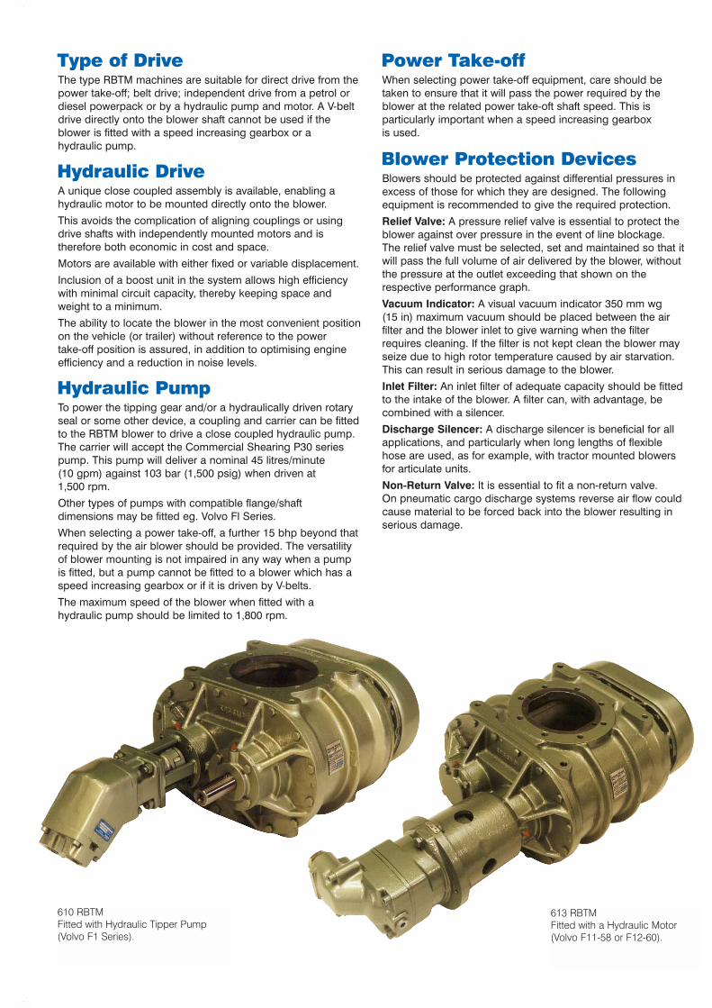
613 RBTMFitted with a Hydraulic Motor(Volvo F11-58 or F12-60).
610 RBTMFitted with Hydraulic Tipper Pump(Volvo F1 Series).

Timing: When a standard machine is to provide a horizontal airflow, the top shaft is extended for the drive. If the machine ismounted for vertical air flow, the drive shaft is on the right. Theposition of the shaft is given when looking at the machine fromthe drive shaft end. Centre timing enables the blower tooperate in either direction. if the machine is required with abottom or left hand shaft extended, all that needs to be done isto turn the gearcase and trough through 180°. Detailedinstructions are given in the installation and operatinginstruction folder.
Tachometer Otftake: A mechanically driven tachometerofftake is available as an option on the gearcase cover. Whilstthis is normally driven from the bottom shaft on a standardmachine, it can easily be changed to the alternative top position.
Performance: The graphs and table below show theperformance as blowers. However all three sizes can operateas exhausters at vacuums up to 475 m bar or combinations ofpressure and vacuum. Please refer to the applicationsdepartment at Dresser Roots for further information onvacuum duties.
Type Minimum MaximumRec.Speed Relief Valve Pressure1000 rpm 1035 m bar1450 rpm 1240 m bar1000 rpm 900 m bar1450 rpm 1035 m bar1000 rpm 840 m bar
* The relief valve should be selected, set and maintained to pass all the volumedelivered without the pressure at the outlet of the blower exceeding the abovemaximum pressure when the minimum recommended speed is that shown in theabove table.Caution: The bhp remains constant for any given impeller speed and outletpressure. When selecting power take-off equipment, relate the bhp to the blowerinput shaft speed if a speed increasing gearbox is used. The torque increases indirect proportion to the blower gearbox ratio.
Performance Graph 68 RBTM Performance Graph 613 RBTM
Performance Graph 610 RBTM
68 RBTM
610 RBTM
613 RBTM
1000
400
600
800
1000
1200
1400
1600
1800
1200 1400 1600 1800 2000 2200 2400BLOWER SPEED (rpm)
INLE
T V
OLU
ME
(m
3 /hr
)
PR
ES
SU
RE
(m
bar)
OU
TLE
T TE
MP.
(˚C
)P
OW
ER
(kW
)
400550700900
130
150
110
90
70
50
60
52.5
45
37.5
30
22.5
15
7.5
400
550
700
900
400
550
700
900
1035
1035
1000
300
600
800
1000
1200
1400
1600
1800
2000
2200
2400
1200 1400 1600 1800 2000 2200 2400BLOWER SPEED (rpm)
INLE
T V
OLU
ME
(m
3 /hr
)
PR
ES
SU
RE
(m
bar)
OU
TLE
T TE
MP.
(˚C
)P
OW
ER
(kW
)
300
500
700
125
110
90
70
50
60
52.5
45
37.5
30
22.5
15
7.5
300
500
700
840
400500
700
840
1240
1100
1035
900
700
500
1240
11001035
900
700
415
1000
300
400
500
600
700
800
900
1000
1100
1200
1300
1200 1400 1600 1800 2000 2200 2400BLOWER SPEED (rpm)
INLE
T V
OLU
ME
(m
3 /hr
)
PR
ES
SU
RE
(m
bar)
OU
TLE
T TE
MP.
(˚C
)P
OW
ER
(kW
)
500700
900
1100
175
150
130
110
90
70
50
60
52.5
45
37.5
30
22.5
15
7.5

A
B
90
Blowers can besupplied as twinshaft versions
Tachometer offtake3/4" x 26 T.P.I.Whitworth form threadfor standard tachometercable fitted withprotective cap
C
9.559.53
38.11338.100
(11/2")
34.2
934
.14
90157
46
91
Inlet and Outlet3/4" BSP
Inlet and Outlet1" BSP
81
123
375 (VOLVO F11)
407 (VOLVO F12)
305
472 152 crs
Tachometerdrive position
Alternative tachometer driveor oil filter position
Oil level filling plugDrain plug
79
133
8 holes tapped12 x 1.75 pitchx 16 deep
4 holes tapped16 x 2 pitch x 22 deep
105
133
8 holes tappedM16 x 2 pitchx 18 deep
4 mounting holestapped M16 x 2 pitchx 18 deep each side
140
140
4 mounting holestapped M16 x 2 pitchx 18 deep each side
STANDARD MACHINE
FLANGES
Bare shaft blower withtipper pump(CS P30)
Hydraulic drive
68 RBTM 610 RBTM 613 RBTM
N.B. Other types of pumps with compatible flange/shaft dimensions may be fitted e.g.Volvo F1 Series
N.B. Volvo tipper pump can be fitted/supplied in combination with Volvo hydraulic drive motors.
BLOWER
68 RBTM610RBTM613 RBTM
A
All dimensions in millimetres
B
601651727
296321359
CWITH
TACHO.305330368
CWITHOUTTACHO.
289312350
NETWEIGHT
Kg120143165

Volumes from 1600 to 7000 m3/hr and vacuums rangingfrom 500 to 900 m bar (i.e. up to 90% vacuum).
Vehicle Exhausters forBulk Collection/Cleaning
Your single sourcefor Vehicle MountedExhausters and Blowers
220 RBT High Performance Blowers forbulk transport vehicles. These unitssupplement the RBTM range andoffer higher pressures (up to 1600 m bar)and lower noise.
220 RBT fitted with HydraulicMotor (Volvo F1-60).
© 2003 Dresser, Inc. JET.RBTM.10.03
DRESSER, Inc.
PO BOX B7, Off St Andrews Road, Huddersfield HD1 6RB England.Tel: +44 (0) 1484 42 22 22 Fax: +44 (0) 1484 42 34 29E-mail: [email protected]
Following the Company’s policy of constantdevelopment we reserve the right to alter anydetail specified or illustrated in this publicationwithout notice and without incurring anyobligation to provide such modifications onmachines previously delivered.


