Position and Orientation Control of an Omni-Directional ... · Position and Orientation Control of...
7
Position and Orientation Control of an Omni-Directional Mobile Rehabilitation Robot Dongfeng Luo 1,3 ,Thomas Schauer 2 , Michael Roth 2 and Jörg Raisch 1,2 Abstract— Position and orientation control for an omni- directional mobile robot are investigated. The table-placed robot shall be used for arm and shoulder rehabilitation of stroke patients. The position and orientation of the device are determined by means of a modified Kalman filter which encompasses a kinematic model of the robot. By fusing infor- mation from incremental encoders at the robot and from an infrared camera at the ceiling, accurate and reliable estimates of robot position and orientation can be obtained. A cascaded position controller is designed for the mobile robot to allow the tracking of arbitrary translational reference movements and the stabilisation of the robot orientation. On the inner control loop, individual angular velocity controllers have been implemented for the three wheels to achieve maximum actuator performance and to facilitate a simplified state-space description of the robot dynamics. For the outer loop, a multi-variable state-space controller is utilised in form of a discrete-time linear quadratic regulator. The sensor fusion scheme and control system are validated in experiments and the obtained results are discussed. I. I NTRODUCTION Robot-aided neuro-rehabilitation has been widely studied in recent years. Robots are not only able to provide repet- itive functional movement training, but also can monitor the movement objectively and quantitatively. A variety of upper limb rehabilitation robots has been developed to as- sist, enhance, evaluate, and document neurological and or- thopaedic rehabilitation of movement, including MIT-Manus [1], [2], GENTLE/s [3], and ARMin [4], [5]. Some of these devices have been proven to reduce motor impairment in the hemiparetic upper limbs of stroke patients. However, these approaches exclusively focused on the clinical setting which entails a lack of mobility, high acquisition costs and limited patient training times. To address some of these issues, concepts that allow stroke patients with upper limb impairments to continue rehabilitation therapy at home must be investigated [6]. In order for the technology to support therapist indepen- dent home rehabilitation, the robot must be designed in a way that the system is less complex so that a patient can use the system without therapist input. These strong requirements, compact design and therapist independence, are currently not met by any active robotic device for training 1 D. Luo and J. Raisch are with the Max Planck Institute for Dynamics of Complex Technical Systems, Magdeburg, Germany 2 T. Schauer, M. Roth and J. Raisch are with the Technis- che Universität Berlin, Control Systems Group, Berlin, Germany, [email protected] 3 D. Luo is with the Xi’an Institute of Optics and Precision Mechanics of CAS, Xi’an, China upper limb functions after stroke. A first attempt is given by the Arm-Skate system [7], a semi-passive table-top device that is lightweight and less cumbersome. The ARMassist device [8] is another passive device that can be operated in a home environment on a standard table. Both devices are simple to set up and affordable for home-based rehabilitation. However, their capabilities are still limited by their lack of active movement support. The Reha-Maus, which is a novel upper limb rehabilitation system developed by the Control Systems Group at TU- Berlin, poses the first concept of a portable rehabilitation robot that actively provides different levels of patient assis- tance. Its compact design and reduced complexity facilitate user friendly home training as well as clinical use, and the implemented control strategy offers guidance and assistance for patient’s arm training. Furthermore, its estimated low price allows for group therapy with several robots in use. Prospective training applications include assisted or per- turbed motion of shoulder and elbow induced by controlled robot motion. Moreover, the utilised sensors and the use of computer control allow for advanced training programs and continuous patient assessment and monitoring. The design of the Reha-Maus is based on a mobile robot driven by omni-directional wheels. The table-placed robot allows simultaneously and independently controlled rotational and translation motion in a plane guiding the hand/lower arm. In the application of omni-directional mobile robot the motion control is the essential component. In [9], a simple resolved-acceleration control with PI and PD feedback has been developed to control the robot velocity and orientation angle. This design was sufficient for mobile service robots. In [10], an integrated control scheme has been developed for robot motion and internal forces based on extension modelling. The designed controller was only tested in simulation. Liu et al. [11] proposed a two-loop controller architecture based on trajectory linearisation. For the nonlinear controller design a precise dynamic nonlinear model of the robot is required. A sensor fusion method, which combines the on-board sensors and the vision system data, was employed to provide accurate and reliable robot po- sition and orientation estimates, thereby reducing the wheel slippage induced tracking error. This contribution describes the motion control system of the Reha-Maus. In the first part of this paper, the concept of this robotic system, the mechanical design, the electron- ics and sensors as well as the software environment are 2012 IEEE International Conference on Control Applications (CCA) Part of 2012 IEEE Multi-Conference on Systems and Control October 3-5, 2012. Dubrovnik, Croatia 978-1-4673-4504-0/12/$31.00 ©2012 IEEE 50
Transcript of Position and Orientation Control of an Omni-Directional ... · Position and Orientation Control of...
Position and Orientation Control of anOmni-Directional Mobile Rehabilitation Robot
Dongfeng Luo1,3,Thomas Schauer2, Michael Roth2 and Jörg Raisch1,2
Abstract— Position and orientation control for an omni-directional mobile robot are investigated. The table-placedrobot shall be used for arm and shoulder rehabilitation ofstroke patients. The position and orientation of the deviceare determined by means of a modified Kalman filter whichencompasses a kinematic model of the robot. By fusing infor-mation from incremental encoders at the robot and from aninfrared camera at the ceiling, accurate and reliable estimatesof robot position and orientation can be obtained. A cascadedposition controller is designed for the mobile robot to allow thetracking of arbitrary translational reference movements and thestabilisation of the robot orientation. On the inner control loop,individual angular velocity controllers have been implementedfor the three wheels to achieve maximum actuator performanceand to facilitate a simplified state-space description of therobot dynamics. For the outer loop, a multi-variable state-spacecontroller is utilised in form of a discrete-time linear quadraticregulator. The sensor fusion scheme and control system arevalidated in experiments and the obtained results are discussed.
I. INTRODUCTION
Robot-aided neuro-rehabilitation has been widely studiedin recent years. Robots are not only able to provide repet-itive functional movement training, but also can monitorthe movement objectively and quantitatively. A variety ofupper limb rehabilitation robots has been developed to as-sist, enhance, evaluate, and document neurological and or-thopaedic rehabilitation of movement, including MIT-Manus[1], [2], GENTLE/s [3], and ARMin [4], [5]. Some of thesedevices have been proven to reduce motor impairment inthe hemiparetic upper limbs of stroke patients. However,these approaches exclusively focused on the clinical settingwhich entails a lack of mobility, high acquisition costs andlimited patient training times. To address some of theseissues, concepts that allow stroke patients with upper limbimpairments to continue rehabilitation therapy at home mustbe investigated [6].
In order for the technology to support therapist indepen-dent home rehabilitation, the robot must be designed ina way that the system is less complex so that a patientcan use the system without therapist input. These strongrequirements, compact design and therapist independence,are currently not met by any active robotic device for training
1 D. Luo and J. Raisch are with the Max Planck Institute for Dynamicsof Complex Technical Systems, Magdeburg, Germany
2 T. Schauer, M. Roth and J. Raisch are with the Technis-che Universität Berlin, Control Systems Group, Berlin, Germany,[email protected]
3 D. Luo is with the Xi’an Institute of Optics and Precision Mechanicsof CAS, Xi’an, China
upper limb functions after stroke. A first attempt is given bythe Arm-Skate system [7], a semi-passive table-top devicethat is lightweight and less cumbersome. The ARMassistdevice [8] is another passive device that can be operatedin a home environment on a standard table. Both devices aresimple to set up and affordable for home-based rehabilitation.However, their capabilities are still limited by their lack ofactive movement support.
The Reha-Maus, which is a novel upper limb rehabilitationsystem developed by the Control Systems Group at TU-Berlin, poses the first concept of a portable rehabilitationrobot that actively provides different levels of patient assis-tance. Its compact design and reduced complexity facilitateuser friendly home training as well as clinical use, and theimplemented control strategy offers guidance and assistancefor patient’s arm training. Furthermore, its estimated lowprice allows for group therapy with several robots in use.Prospective training applications include assisted or per-turbed motion of shoulder and elbow induced by controlledrobot motion. Moreover, the utilised sensors and the use ofcomputer control allow for advanced training programs andcontinuous patient assessment and monitoring.
The design of the Reha-Maus is based on a mobilerobot driven by omni-directional wheels. The table-placedrobot allows simultaneously and independently controlledrotational and translation motion in a plane guiding thehand/lower arm.
In the application of omni-directional mobile robot themotion control is the essential component.
In [9], a simple resolved-acceleration control with PI andPD feedback has been developed to control the robot velocityand orientation angle. This design was sufficient for mobileservice robots. In [10], an integrated control scheme hasbeen developed for robot motion and internal forces basedon extension modelling. The designed controller was onlytested in simulation. Liu et al. [11] proposed a two-loopcontroller architecture based on trajectory linearisation. Forthe nonlinear controller design a precise dynamic nonlinearmodel of the robot is required. A sensor fusion method,which combines the on-board sensors and the vision systemdata, was employed to provide accurate and reliable robot po-sition and orientation estimates, thereby reducing the wheelslippage induced tracking error.
This contribution describes the motion control system ofthe Reha-Maus. In the first part of this paper, the conceptof this robotic system, the mechanical design, the electron-ics and sensors as well as the software environment are
2012 IEEE International Conference on Control Applications (CCA)Part of 2012 IEEE Multi-Conference on Systems and ControlOctober 3-5, 2012. Dubrovnik, Croatia
978-1-4673-4504-0/12/$31.00 ©2012 IEEE 50
presented. In the second part, as basis for the followingsections, the kinematics of mobile platform are describedin detail. Thirdly, a sensor fusion scheme, which combinesglobal absolute position measurements and encoder data toprovide an accurate and reliable estimation of robot positionand orientation, is presented. In addition to the work in [11],a delay between the measurement systems was taken intoaccount. In the fourth place, the paper describes the design ofthe cascaded multi-variable position control scheme for thetracking of arbitrary reference motions. In contrast to otherstudies, the design is only based on the kinematic model andan experimentally identified simple transfer function modelof the wheel speed dynamics. Finally, experimental resultsof sensor fusion and position controller are given.
II. OMNI-DIRECTIONAL ROBOT
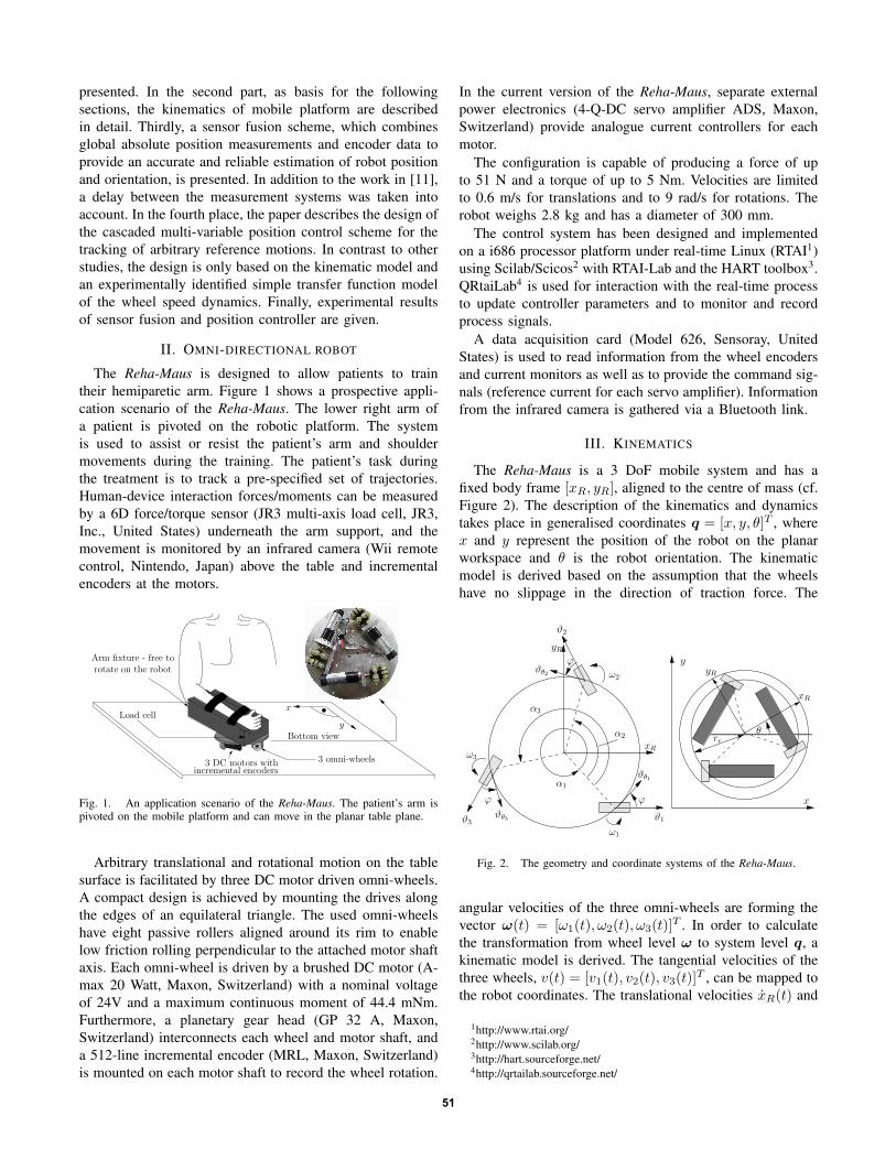
The Reha-Maus is designed to allow patients to traintheir hemiparetic arm. Figure 1 shows a prospective appli-cation scenario of the Reha-Maus. The lower right arm ofa patient is pivoted on the robotic platform. The systemis used to assist or resist the patient’s arm and shouldermovements during the training. The patient’s task duringthe treatment is to track a pre-specified set of trajectories.Human-device interaction forces/moments can be measuredby a 6D force/torque sensor (JR3 multi-axis load cell, JR3,Inc., United States) underneath the arm support, and themovement is monitored by an infrared camera (Wii remotecontrol, Nintendo, Japan) above the table and incrementalencoders at the motors.
3 DC motors withincremental encoders
3 omni-wheels
Arm fixture - free torotate on the robot
Load cell
Bottom viewy
x
Fig. 1. An application scenario of the Reha-Maus. The patient’s arm ispivoted on the mobile platform and can move in the planar table plane.
Arbitrary translational and rotational motion on the tablesurface is facilitated by three DC motor driven omni-wheels.A compact design is achieved by mounting the drives alongthe edges of an equilateral triangle. The used omni-wheelshave eight passive rollers aligned around its rim to enablelow friction rolling perpendicular to the attached motor shaftaxis. Each omni-wheel is driven by a brushed DC motor (A-max 20 Watt, Maxon, Switzerland) with a nominal voltageof 24V and a maximum continuous moment of 44.4 mNm.Furthermore, a planetary gear head (GP 32 A, Maxon,Switzerland) interconnects each wheel and motor shaft, anda 512-line incremental encoder (MRL, Maxon, Switzerland)is mounted on each motor shaft to record the wheel rotation.
In the current version of the Reha-Maus, separate externalpower electronics (4-Q-DC servo amplifier ADS, Maxon,Switzerland) provide analogue current controllers for eachmotor.
The configuration is capable of producing a force of upto 51 N and a torque of up to 5 Nm. Velocities are limitedto 0.6 m/s for translations and to 9 rad/s for rotations. Therobot weighs 2.8 kg and has a diameter of 300 mm.
The control system has been designed and implementedon a i686 processor platform under real-time Linux (RTAI1)using Scilab/Scicos2 with RTAI-Lab and the HART toolbox3.QRtaiLab4 is used for interaction with the real-time processto update controller parameters and to monitor and recordprocess signals.
A data acquisition card (Model 626, Sensoray, UnitedStates) is used to read information from the wheel encodersand current monitors as well as to provide the command sig-nals (reference current for each servo amplifier). Informationfrom the infrared camera is gathered via a Bluetooth link.
III. KINEMATICS
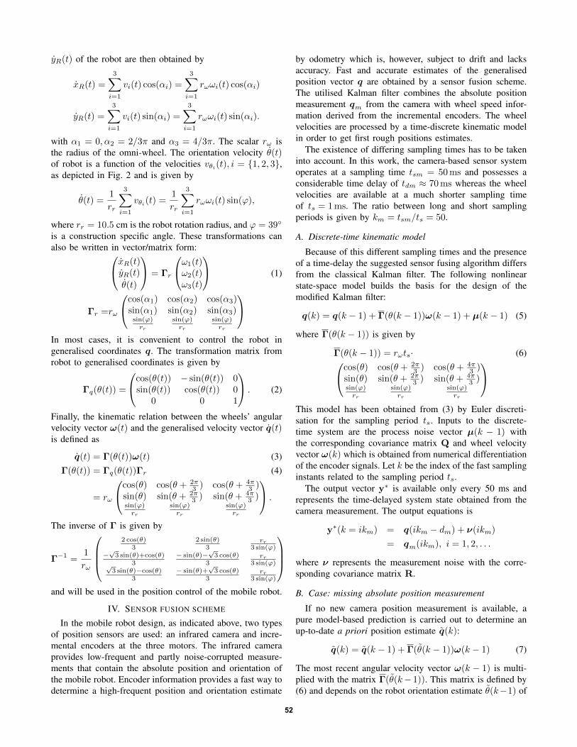
The Reha-Maus is a 3 DoF mobile system and has afixed body frame [xR, yR], aligned to the centre of mass (cf.Figure 2). The description of the kinematics and dynamicstakes place in generalised coordinates q = [x, y, θ]T , wherex and y represent the position of the robot on the planarworkspace and θ is the robot orientation. The kinematicmodel is derived based on the assumption that the wheelshave no slippage in the direction of traction force. The
ω2
ϕ
ϑ3ϑθ3
ϕ
ω3
α1
ϑθ1
α2
α3
ω1
ϑ1
ϕ
ϑθ2
ϑ2
x
y
rrθ
yR
xR
xR
yR
Fig. 2. The geometry and coordinate systems of the Reha-Maus.
angular velocities of the three omni-wheels are forming thevector ω(t) = [ω1(t), ω2(t), ω3(t)]
T . In order to calculatethe transformation from wheel level ω to system level q, akinematic model is derived. The tangential velocities of thethree wheels, v(t) = [v1(t), v2(t), v3(t)]
T , can be mapped tothe robot coordinates. The translational velocities xR(t) and
1http://www.rtai.org/2http://www.scilab.org/3http://hart.sourceforge.net/4http://qrtailab.sourceforge.net/
51
yR(t) of the robot are then obtained by
xR(t) =
3∑i=1
vi(t) cos(αi) =
3∑i=1
rωωi(t) cos(αi)
yR(t) =
3∑i=1
vi(t) sin(αi) =
3∑i=1
rωωi(t) sin(αi).
with α1 = 0, α2 = 2/3π and α3 = 4/3π. The scalar rω isthe radius of the omni-wheel. The orientation velocity θ(t)of robot is a function of the velocities vθi(t), i = {1, 2, 3},as depicted in Fig. 2 and is given by
θ(t) =1
rr
3∑i=1
vθi(t) =1
rr
3∑i=1
rωωi(t) sin(ϕ),
where rr = 10.5 cm is the robot rotation radius, and ϕ = 39◦
is a construction specific angle. These transformations canalso be written in vector/matrix form:xR(t)yR(t)
θ(t)
= Γr
ω1(t)ω2(t)ω3(t)
(1)
Γr =rω
cos(α1) cos(α2) cos(α3)sin(α1) sin(α2) sin(α3)sin(ϕ)rr
sin(ϕ)rr
sin(ϕ)rr
In most cases, it is convenient to control the robot ingeneralised coordinates q. The transformation matrix fromrobot to generalised coordinates is given by
Γq(θ(t)) =
cos(θ(t)) − sin(θ(t)) 0sin(θ(t)) cos(θ(t)) 0
0 0 1
. (2)
Finally, the kinematic relation between the wheels’ angularvelocity vector ω(t) and the generalised velocity vector q(t)is defined as
q(t) = Γ(θ(t))ω(t) (3)Γ(θ(t)) = Γq(θ(t))Γr (4)
= rω
cos(θ) cos(θ + 2π3 ) cos(θ + 4π
3 )sin(θ) sin(θ + 2π
3 ) sin(θ + 4π3 )
sin(ϕ)rr
sin(ϕ)rr
sin(ϕ)rr
.
The inverse of Γ is given by
Γ−1 =1
rω
2 cos(θ)
32 sin(θ)
3rr
3 sin(ϕ)−√3 sin(θ)+cos(θ)
3− sin(θ)−
√3 cos(θ)
3rr
3 sin(ϕ)√3 sin(θ)−cos(θ)
3− sin(θ)+
√3 cos(θ)
3rr
3 sin(ϕ)
and will be used in the position control of the mobile robot.
IV. SENSOR FUSION SCHEME
In the mobile robot design, as indicated above, two typesof position sensors are used: an infrared camera and incre-mental encoders at the three motors. The infrared cameraprovides low-frequent and partly noise-corrupted measure-ments that contain the absolute position and orientation ofthe mobile robot. Encoder information provides a fast way todetermine a high-frequent position and orientation estimate
by odometry which is, however, subject to drift and lacksaccuracy. Fast and accurate estimates of the generalisedposition vector q are obtained by a sensor fusion scheme.The utilised Kalman filter combines the absolute positionmeasurement qm from the camera with wheel speed infor-mation derived from the incremental encoders. The wheelvelocities are processed by a time-discrete kinematic modelin order to get first rough positions estimates.
The existence of differing sampling times has to be takeninto account. In this work, the camera-based sensor systemoperates at a sampling time tsm = 50ms and possesses aconsiderable time delay of tdm ≈ 70ms whereas the wheelvelocities are available at a much shorter sampling timeof ts = 1ms. The ratio between long and short samplingperiods is given by km = tsm/ts = 50.
A. Discrete-time kinematic model
Because of this different sampling times and the presenceof a time-delay the suggested sensor fusing algorithm differsfrom the classical Kalman filter. The following nonlinearstate-space model builds the basis for the design of themodified Kalman filter:
q(k) = q(k − 1) + Γ(θ(k − 1))ω(k − 1) + µ(k − 1) (5)
where Γ(θ(k − 1)) is given by
Γ(θ(k − 1)) = rωts· (6)cos(θ) cos(θ + 2π3 ) cos(θ + 4π
3 )sin(θ) sin(θ + 2π
3 ) sin(θ + 4π3 )
sin(ϕ)rr
sin(ϕ)rr
sin(ϕ)rr
This model has been obtained from (3) by Euler discreti-sation for the sampling period ts. Inputs to the discrete-time system are the process noise vector µ(k − 1) withthe corresponding covariance matrix Q and wheel velocityvector ω(k) which is obtained from numerical differentiationof the encoder signals. Let k be the index of the fast samplinginstants related to the sampling period ts.
The output vector y∗ is available only every 50 ms andrepresents the time-delayed system state obtained from thecamera measurement. The output equations is
y∗(k = ikm) = q(ikm − dm) + ν(ikm)
= qm(ikm), i = 1, 2, . . .
where ν represents the measurement noise with the corre-sponding covariance matrix R.
B. Case: missing absolute position measurement
If no new camera position measurement is available, apure model-based prediction is carried out to determine anup-to-date a priori position estimate q(k):
q(k) = q(k − 1) + Γ(θ(k − 1))ω(k − 1) (7)
The most recent angular velocity vector ω(k − 1) is multi-plied with the matrix Γ(θ(k− 1)). This matrix is defined by(6) and depends on the robot orientation estimate θ(k−1) of
52
the last time step. Hence, Eq. (7) is computed for samplinginstants where only ω is updated.
The update equation for the a priori covariance matrix ofthe state estimate is given by
P(k) = P(k − 1) + Q (8)
Please note, that in the Eqs. (7) and (8) a priori estimatesalso appear on the right sides of the equations. Because ofthe time delay dm > 1, a posteriori estimates do not existfor the time instant k − 1.
C. Case: present absolute position measurement
Once a camera measurement y∗(k) = qm(k) = q(k −dm)+ν(k) is available, one can determine the Kalman gainK(k − dm) as well as the a posteriori estimates q(k− dm)and P(k − dm) of the state and the covariance matrixrespectively for the past time instant k − dm:
K(k − dm) = P(k − dm)(P(k − dm) + R)−1 , (9)
P(k − dm) = (I−K(k − dm))P(k − dm) (10)q(k − dm) = q(k − dm)+
K(k − dm) (y∗(k)− q(k − dm)) . (11)
These calculations require that old a priori estimates andwheel velocities are temporally stored. Based on the obtaineda posterior estimates, new a priori estimates q and P canbe iteratively calculated from the time instant k− dm+1 tothe current time instant k:
q(k − dm + 1) = q(k − dm) + Γ(θ(k − dm))ω(k − dm)
P(k − dm + 1) = P(k − dm) + Q
q(k − dm + i) = q(k − dm + i− 1) +
Γ(θ(k − dm + i− 1)) ·ω(k − dm + i− 1), i = 2, . . . , dm
P(k − dm + i) = P(k − dm + i− 1) + Q,
i = 2, . . . , dm
The proposed algorithm accounts for a non-negligible trans-mission delay in the camera-based measurement system.
V. POSITION CONTROL
To execute arbitrary robot movements, a cascaded discrete-time position controller is developed while assuming a neg-ligible dynamics for the state observer, i.e. q(k) = q(k).
The inner loop consists of three independent motor speedcontrollers to operate the system at maximum actuator ca-pacity and to facilitate a simplified state-space description ofthe robot. For the outer loop, an optimal position controlleris used based on a discrete-time linear quadratic regulator(LQR) design.
A. Inner loop: wheel speed control
Each DC motor is powered by an individual powerelectronics offering analogue motor current control. Con-sequently, the reference motor currents Iri , i ∈ {1, 2, 3},represent the manipulable process input signals. Controlledsignals at the inner loop level are the motor wheel speeds
ωi(k), i ∈ {1, 2, 3}. The relation between the speed of awheel and the corresponding reference current is approxi-mately described by a simple pulse transfer function model
ωi(k) =B(q−1)
A(q−1)Iri(k) +
1
A(q−1)(1− q−1)e(k) (12)
with the polynomials A(q−1) = 1 + a1q−1 and B(q−1) =
b0q−1. Here, k is the sample index, e(k) represents a noise
input and q−1 is the back-shift operator (q−1s(k) = s(k−1)).A sampling time ts of one millisecond is used as before inthe sensor fusion.
The transfer function (12) can be experimentally identified[12]. Only one wheel of the robot with the arm load will beactivated by a square wave reference current signal. Thissignal has to be chosen carefully to not operate the motor atmaximal speed in order to allow linear system identification.
In order to track the demanded reference wheel speedsωri , i ∈ {1, 2, 3} (generated from the outer control loop), thefollowing digital controller in polynomial form is applied foreach motor [13]:
Iri(k) =1
R(q−1)(−S(q−1)ωi(k) + T(q−1)ωri). (13)
The feedback part of the controller possesses a pole at one(to have integral action) and a zero at minus one (to eliminatethe effect of noise at the Nyquist frequency):
R(q−1) = R(q−1)(1− q−1), (14)S(q−1) = S(q−1)(1 + q−1). (15)
The factors R and S of the controller polynomials aredetermined by pole-placement. The characteristic polynomialAcl(q
−1) of the closed-loop system (inner loop) is given by
Acl = AR · (1− q−1) + BS · (1 + q−1) , Adcl. (16)
The polynomials R and S have to be determined in sucha way that a desired, pre-specified, closed-loop polynomialAdcl is obtained. For a minimal degree controller we chosedegAdcl = 3, deg S = 1 and degR = 1. The polynomial Adclwill be factorised into a first and second order polynomial
Adcl(q−1) = Ao(q
−1)Ar(q−1)
Ar(q−1) = 1− ar1q−1 = 1− ets/trr q−1
Ao(q−1) = 1− 2e−ω0tsq−1 + e−2ω0tsq−2
with ω0 = 3.2/tro . Both polynomials, Ar and Ao, yield ofcourse stable system behaviour and characterise the closed-loop dynamics. Tuning parameters of the wheel speed con-trol loops are the rise times trr and tro associated withpolynomials Ar and Ao respectively. The desired transferfunction from the reference wheel speed to the actual wheelspeed shall be of first order with the polynomial Ar(q−1) asdenumerator and an unity DC gain:
Tω(q−1) =
ωi
ωri=q−1Ar(1)
Ar(q−1)=q−1(1− ar1)1− ar1q−1
(17)
53
To fulfil (17) the pre-filter polynomial T(q−1) of the con-troller has to be chosen as
T(q−1) =Ao(q
−1)Ar(1)
B(1). (18)
Each speed controller has been implemented with an anti-windup-scheme as proposed in [13].
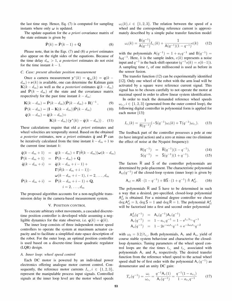
B. Outer loop: state space position controller
ωr[k]
Iinversekinematictransform
simplified ω control loop kinematic model
1/q1/q
qr(k)
Γ(k)−1 (1− ar1)I
ar1I
ω(k)
Γ(k)
q(k)
Fig. 3. Time-variant state-space model with the reference velocity as inputand the actual position as output (both in generalised coordinates).
The relationship between reference wheel velocity vectorωr and actual wheel velocity vector ω can be expressed bya single state-difference equation
ω(k + 1) = (1− ar1)ωr(k) + ar1ω(k) . (19)
Combining the kinematic model (7) (assuming a negligibledynamics for the state observer, i.e. q(k) = q(k)) withthe wheel speed dynamics (19) yields a linear time-varyingmodel with the state
x(k) =
(q(k)ω(k)
).
Let I and O be the 3 × 3 identity and zero matrix,respectively. Then, the combined state-difference equationcan be formulated as(q(k + 1)ω(k + 1)
)=
(I Γ(k)O ar1I
)(q(k)ω(k)
)+
(O
(1− ar1)I
)ωr(k) (20)
The whole state x(k) is accessible by measurement orestimation. The desired output is the generalised position.Hence, the output equation is given by
y(k) =(I O
)(q(k)ω(k)
). (21)
In order to improve disturbance rejection and facilitatethe use of a linear state feedback design, the plant isapproximately linearised. The linearisation is accomplishedby augmenting the existing model with an inverse of thekinematic transformation ωr(k) = Γ(k)qr(k). The corre-sponding state-space representation is then given by(
q(k + 1)ω(k + 1)
)=
(I Γ(k)O ar1I
)(q(k)ω(k)
)+
(O
(1− ar1)Γ−1
(k)
)qr(k). (22)
The input signal for the augmented system is now the refer-ence velocity qr(k) in generalised coordinates. As shown in
Figure 3, both time-varying transformation matrices Γ(k)−1
and Γ(k) are interconnected through the wheel velocitysubsystem.
The actual design procedure can now be carried out for onelinearised plant, i.e. one pair of Γ(k) and its correspondinginverse, evaluated at a fixed robot orientation θ0. This ap-proach is valid if the desired orientation angle is equal θ0 andif the controlled orientation angle remains close to the desiredone. In this work, an orientation of θ0 = 0 rad is chosen aslinearisation and reference angle. The corresponding matrixΓ0 and its inverse Γ
−10 are constant. The resulting linear
time-invariant model for the controller design can now beformulated as(
q(k + 1)ω(k + 1)
)≈
(I Γ0
O ar1I
)(q(k)ω(k)
)+
+
(O
(1− ar1)Γ−10
)qr(k) . (23)
The output equation (21) remains unchanged. The utilisedstate-space feedback control is based on a Linear QuadraticRegulator (LQR) problem [14]. The control design objectiveis to minimise the following cost function:
Ju =
∞∑k=k0
(xT (k)Qcx(k) + u
T (k)Rcu(k))
(24)
where Qc and Rc are symmetric weighting matrices for thestate x(k) and the control input u(k) = qr(k). The matrixQc is assumed to be non-negative definite, whereas Rc mustbe positive definite. The resulting optimal control signal isobtained as a state-feedback law given by
L = (B′P∞B + Rc)−1B′P∞A, (25)
u(k) = −Lx(k) + Fqr(k). (26)
P∞ is the solution of the following discrete-time Ricattiequation
P∞ = A′(P∞ −P∞B(B′P∞B + Rc)
−1B′P∞)A+Qc.
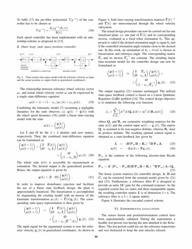
(27)The linear system matrices for controller design, A, B andC, can be extracted from the nominal model given by (21)and (23). Furthermore, a reference filter F is designed toprovide an unity DC gain for the command response. As theregarded system has six states and three manipulable inputs,the resulting controller matrix L is of dimension 3× 6. Thereference filter is a 3× 3 square matrix.
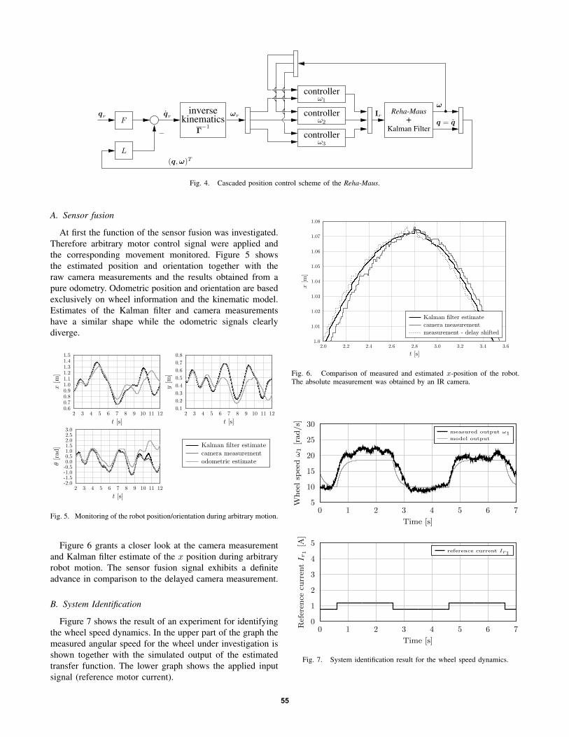
Figure 4 illustrates the cascaded control scheme.
VI. EXPERIMENTAL EVALUATION
The sensor fusion and position/orientation control havebeen experimentally validated. During the experiments ahealthy test person was having the arm attached to the Reha-Maus. The test person could not see the reference trajectoriesand was instructed to keep the arm muscles relaxed.
54
inverse
kinematicscontroller
controller
+
controller
Kalman Filter
L
F
Γ−1
−
ω1
ω2
ω3
qr qr ωr Reha-Mausω
Irq = q
(q,ω)T
Fig. 4. Cascaded position control scheme of the Reha-Maus.
A. Sensor fusion
At first the function of the sensor fusion was investigated.Therefore arbitrary motor control signal were applied andthe corresponding movement monitored. Figure 5 showsthe estimated position and orientation together with theraw camera measurements and the results obtained from apure odometry. Odometric position and orientation are basedexclusively on wheel information and the kinematic model.Estimates of the Kalman filter and camera measurementshave a similar shape while the odometric signals clearlydiverge.
x[m
]
t [s]
y[m
]
t [s]
θ[r
ad
]
t [s]
Kalman filter estimatecamera measurementodometric estimate
Fig. 5. Monitoring of the robot position/orientation during arbitrary motion.
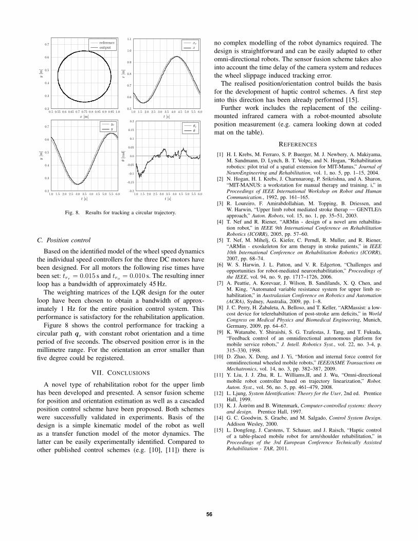
Figure 6 grants a closer look at the camera measurementand Kalman filter estimate of the x position during arbitraryrobot motion. The sensor fusion signal exhibits a definiteadvance in comparison to the delayed camera measurement.
B. System Identification
Figure 7 shows the result of an experiment for identifyingthe wheel speed dynamics. In the upper part of the graph themeasured angular speed for the wheel under investigation isshown together with the simulated output of the estimatedtransfer function. The lower graph shows the applied inputsignal (reference motor current).
x[m
]
t [s]
Kalman filter estimatecamera measurementmeasurement - delay shifted
Fig. 6. Comparison of measured and estimated x-position of the robot.The absolute measurement was obtained by an IR camera.
Wheelsp
eedω1[rad/s]
Time [s]
measured output ω1model output
Referen
cecu
rren
tI r
1[A
]
Time [s]
reference current Ir1
Fig. 7. System identification result for the wheel speed dynamics.
55
y[m
]
x [m]
referenceoutput
x[m
]
t [s]
xrx
y[m
]
t [s]
yry
θ[rad
]
t [s]
θrθ
Fig. 8. Results for tracking a circular trajectory.
C. Position control
Based on the identified model of the wheel speed dynamicsthe individual speed controllers for the three DC motors havebeen designed. For all motors the following rise times havebeen set: trr = 0.015 s and tro = 0.010 s. The resulting innerloop has a bandwidth of approximately 45 Hz.
The weighting matrices of the LQR design for the outerloop have been chosen to obtain a bandwidth of approx-imately 1 Hz for the entire position control system. Thisperformance is satisfactory for the rehabilitation application.
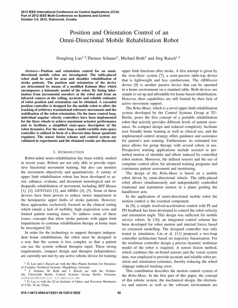
Figure 8 shows the control performance for tracking acircular path qr with constant robot orientation and a timeperiod of five seconds. The observed position error is in themillimetre range. For the orientation an error smaller thanfive degree could be registered.
VII. CONCLUSIONS
A novel type of rehabilitation robot for the upper limbhas been developed and presented. A sensor fusion schemefor position and orientation estimation as well as a cascadedposition control scheme have been proposed. Both schemeswere successfully validated in experiments. Basis of thedesign is a simple kinematic model of the robot as wellas a transfer function model of the motor dynamics. Thelatter can be easily experimentally identified. Compared toother published control schemes (e.g. [10], [11]) there is
no complex modelling of the robot dynamics required. Thedesign is straightforward and can be easily adapted to otheromni-directional robots. The sensor fusion scheme takes alsointo account the time delay of the camera system and reducesthe wheel slippage induced tracking error.
The realised position/orientation control builds the basisfor the development of haptic control schemes. A first stepinto this direction has been already performed [15].
Further work includes the replacement of the ceiling-mounted infrared camera with a robot-mounted absoluteposition measurement (e.g. camera looking down at codedmat on the table).
REFERENCES
[1] H. I. Krebs, M. Ferraro, S. P. Buerger, M. J. Newbery, A. Makiyama,M. Sandmann, D. Lynch, B. T. Volpe, and N. Hogan, “Rehabilitationrobotics: pilot trial of a spatial extension for MIT-Manus,” Journal ofNeuroEngineering and Rehabilitation, vol. 1, no. 5, pp. 1–15, 2004.
[2] N. Hogan, H. I. Krebs, J. Charnnarong, P. Srikrishna, and A. Sharon,“MIT-MANUS: a workstation for manual therapy and training. i,” inProceedings of IEEE International Workshop on Robot and HumanCommunication., 1992, pp. 161–165.
[3] R. Loureiro, F. Amirabdollahian, M. Topping, B. Driessen, andW. Harwin, “Upper limb robot mediated stroke therap — GENTLE/sapproach,” Auton. Robots, vol. 15, no. 1, pp. 35–51, 2003.
[4] T. Nef and R. Riener, “ARMin - design of a novel arm rehabilita-tion robot,” in IEEE 9th International Conference on RehabilitationRobotics (ICORR), 2005, pp. 57–60.
[5] T. Nef, M. Mihelj, G. Kiefer, C. Perndl, R. Muller, and R. Riener,“ARMin - exoskeleton for arm therapy in stroke patients,” in IEEE10th International Conference on Rehabilitation Robotics (ICORR),2007, pp. 68–74.
[6] W. S. Harwin, J. L. Patton, and V. R. Edgerton, “Challenges andopportunities for robot-mediated neurorehabilitation,” Proceedings ofthe IEEE, vol. 94, no. 9, pp. 1717–1726, 2006.
[7] A. Peattie, A. Korevaar, J. Wilson, B. Sandilands, X. Q. Chen, andM. King, “Automated variable resistance system for upper limb re-habilitation,” in Australasian Conference on Robotics and Automation(ACRA), Sydney, Australia, 2009, pp. 1–8.
[8] J. C. Perry, H. Zabaleta, A. Belloso, and T. Keller, “ARMassist: a low-cost device for telerehabiltation of post-stroke arm deficits,” in WorldCongress on Medical Physics and Biomedical Engineering, Munich,Germany, 2009, pp. 64–67.
[9] K. Watanabe, Y. Shiraishi, S. G. Tzafestas, J. Tang, and T. Fukuda,“Feedback control of an omnidirectional autonomous platform formobile service robots,” J. Intell. Robotics Syst., vol. 22, no. 3-4, p.315–330, 1998.
[10] D. Zhao, X. Deng, and J. Yi, “Motion and internal force control foromnidirectional wheeled mobile robots,” IEEE/ASME Transactions onMechatronics, vol. 14, no. 3, pp. 382–387, 2009.
[11] Y. Liu, J. J. Zhu, R. L. Williams,II, and J. Wu, “Omni-directionalmobile robot controller based on trajectory linearization,” Robot.Auton. Syst., vol. 56, no. 5, pp. 461–479, 2008.
[12] L. Ljung, System Identification: Theory for the User, 2nd ed. PrenticeHall, 1999.
[13] K. J. Åström and B. Wittenmark, Computer-controlled systems: theoryand design. Prentice Hall, 1997.
[14] G. C. Goodwin, S. Graebe, and M. Salgado, Control System Design.Addison Wesley, 2000.
[15] L. Dongfeng, J. Carstens, T. Schauer, and J. Raisch, “Haptic controlof a table-placed mobile robot for arm/shoulder rehabilitation,” inProceedings of the 3rd European Conference Technically AssistedRehabilitation - TAR, 2011.
56