PORTER PRECISION · Only available in Standard Point Length. *Ejector Kits available see page 41...
52
PORTER PRECISION PRODUCTS CO. PORTER PRECISION ®
Transcript of PORTER PRECISION · Only available in Standard Point Length. *Ejector Kits available see page 41...

Corporate Office & Manufacturing Plant2734 Banning Rd., Cincinnati, Ohio 45253-8706
Ph: (513) 923-3777 • Fax: (513) 923-1111Toll Free (800) 543-7041
Georgia Manufacturing Plant660 James Rd., Alpharetta, Ga. 30004
Ph: (770) 751-7234 • Fax: (770) 751-7238Toll Free: (800) 437-5185
Canada Plant30 Duke Street West, Suite #503
Kitchener, Ontario, Canada N2H 3W5Ph: (519) 746-3130 • Fax: (519) 746-6960
Toll Free: [email protected]
World Class Products That Perform!
PORTER PRECISION PRODUCTS CO.
PORTER PRECISION PRODUCTS CO.
www.porterpunch.com
PORTERPRECISION
®
BD BDW GL GD GU
SAPQ SAPN PAPQ PAPN
2 © 2017 — Porter Precision Products Company
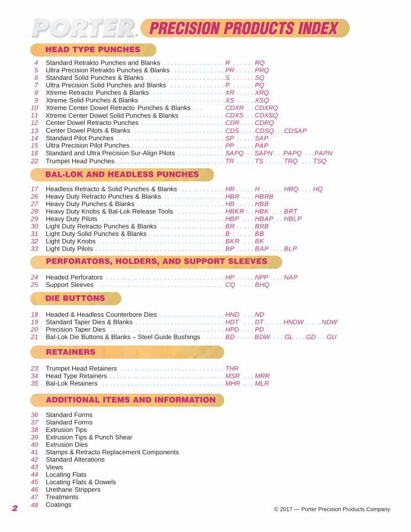
4 Standard Retrakto Punches and Blanks . . . . . . . . . . . . . . . . . R . . . . . . RQ5 Ultra Precision Retrakto Punches & Blanks . . . . . . . . . . . . . . PR . . . . . PRQ6 Standard Solid Punches & Blanks . . . . . . . . . . . . . . . . . . . . . .
. . . . . . . . . . . . . . . . . . . .
S . . . . . . SQ7 Ultra Precision S
Solid Punches & Blanks
olid Punches and Blanks . . . . . . . . . . . . . . . P . . . . . . PQ
9 Xtreme XS . . . . . XSQ8 Xtreme Retracto Punches & Blanks XR . . . . . XRQ
Xtreme Center Dowel Retracto Punches & Blanks . . . CDXR . .
. .
CDXRQ10Xtreme Center Dowel Solid Punches & Blanks CDXS . . .
. . .CDXSQ11
Center Dowel Retracto PunchesCenter Dowel Pilots & BlanksStandard Pilot Punches
Standard and Ultra Precision Sur-Align PilotsUltra Precision Pilot Punches
. . . . . . . . . . . . . . . . . . . . . . .
. . . . . . . . . . . . . . . . . . . . . . .
CDR . CDRQ12 . . . . . . . . . . . . . . . . . . . . . . . . . CDS CDSQ CDSAP . . . . . . .13
SP . . . . . . . . . .
SAP1415
. . . . . . . . . . . .
PP PAP16 . . . . . . . . . . . . .
. . . . . . . . . . . . . . . . . . . . . . . . . . . . . . . . . . . . . . . . . . . . . . . . . . . . . . . .
22 Trumpet Head Punches . . . . . . . . . . . . . . . . . . . . . . . . . . . . . . TR . . . . . TS . . . . . TRQ . . . . . . . . .
TSQ
17 Headless Retracto & Solid Punches & Blanks . . . . . . . . . . . . HR . . . . . H . . . . . . HRQ . . . HQ26 Heavy Duty Retracto Punches & Blanks . . . . . . . . . . . . . . . . . HBR . . . HBRB27 Heavy Duty Punches & Blanks . . . . . . . . . . . . . . . . . . . . . . . . HB . . . . . HBB28 Heavy Duty Knobs & Bal-Lok Release Tools . . . . . . . . . . . . . HBKR . . HBK . . . BRT29 Heavy Duty Pilots . . . . . . . . . . . . . . . . . . . . . . . . . . . . . . . . . . HBP . . . HBAP . . HBLP30 Light Duty Retracto Punches & Blanks . . . . . . . . . . . . . . . . . . BR . . . . . BRB31 Light Duty Solid Punches & Blanks . . . . . . . . . . . . . . . . . . . . . B . . . . . . BB32 Light Duty Knobs . . . . . . . . . . . . . . . . . . . . . . . . . . . . . . . . . . . BKR . . . BK33 Light Duty Pilots . . . . . . . . . . . . . . . . . . . . . . . . . . . . . . . . . . . . BP . . . . . BAP . . . BLP
24 Headed Perforators . . . . . . . . . . . . . . . . . . . . . . . . . . . . . . . . . HP . . . . . NPP . . . NAP25 Support Sleeves . . . . . . . . . . . . . . . . . . . . . . . . . . . . . . . . . . . CQ . . . . BHQ
18 Headed & Headless Counterbore Dies . . . . . . . . . . . . . . . . . . HND . . . ND19 Standard Taper Dies & Blanks . . . . . . . . . . . . . . . . . . . . . . . . . HDT . . . . . . . .
. . . . . . . . . .
. . . . .D HNDW NDWT20 Precision Taper Dies . . . . . . . . . . . . . . . . . . . . . . . . . . . . . . . . HPD . . .
. . . . . . . . .PD
21 Bal-Lok Die Buttons & Blanks – Steel Guide Bushings
23 Trumpet Head Retainers . . . . . . . . . . . . . . . . . . . . . . . . . . . . . THR34 Head Type Retainers . . . . . . . . . . . . . . . . . . . . . . . . . . . . . . . . MSR . . . MRR35 Bal-Lok Retainers . . . . . . . . . . . . . . . . . . . . . . . . . . . . . . . . . . MHR . . . MLR
36 Standard Forms37 Standard Forms38 Extrusion Tips39 Extrusion Tips & Punch Shear
Extrusion Dies4041 Stamps & Retracto Replacement Components
Standard Alterations42Views43Locating Flats44Locating Flats & Dowels45Urethane Strippers46
4748
TCoatings
reatments
BAL-LOK AND HEADLESS PUNCHES
PERFORATORS, HOLDERS, AND SUPPORT SLEEVES
DIE BUTTONS
RETAINERS
HEAD TYPE PUNCHES
ADDITIONAL ITEMS AND INFORMATION
PRECISION PRODUCTS INDEX

3
Description 1-19 Pieces 20-50 PiecesBlanks, Steel Springs, Urethane 1 1Round Punches (Circular Point) 2 5Round Dies (Circular ID) 2 5Shape Punches (flatted round, oblong, square, rectangle) 4 7Shape Dies (flatted round, oblong, square, rectangle) 4 7‘Z' Shapes - (01 - 16) Page 36 & 37 6 9‘Z' Shapes - (All Others) Page 36 & 37 8 11Pilots 3 5Knob Style Punches - Pages 28 & 32 8 12Guide Bushings - Page 21 3 10Durable Line - Pages 24 & 25 Quote Quote‘EX' Shapes, Pages 38 – 40 5 7Xtreme Punch - Pages 8 – 11 3 10Center Dowel - Pages 12 & 13 3 10Specials Quote QuoteCoatings - Page 46 Add 5 Days Add 5 DaysLocating Methods - Pages 44 & 45 Add 0 Days Add 1 DayStandard Alterations - Page 42Group (1) Below - up to 2 alterations Add 0 Days Add 0 DaysGroup (2) Below - each alteration Add 1 Day Add 2 DaysGroup (1) - RL/RT/RH/LPC/LPW/RP/RW/AP/AW & (AB/IB - for Taper Relief Die Matrix)Group (2) - PRL/RD/PRT/AR/SK & (AB/IB - for Stepped Relief Die Matrix)
STANDARD CATALOG ITEMS (Up to 32 mm Ø Body)NUMBER OF WORK DAYS TO SHIPMENT
Allow Additional Time for Multiple Line Item Orders Over 150 Total Pieces Round, or 50 Total Pieces Shape - or Combinations Thereof - Call For Quote
NOTE: THE DAY OF RECEIPT OF THE ORDER IS NOT CONSIDEREDA WORK DAY
WILL SHIP TODAYORDER MUST BE ENTERED BY NOON E.S.T. - and confirmed by phoneUp to Ø 25 mm bodyM2 steel only;Catalog Rounds - up to 9 pieces with maximum of one alteration Catalog Shapes - (flat round, oblong, square and rect.) up to 4 pieces/1 alterationLocking Methods - single and double flatsItems not available for this service
Knob Style PunchesCoatings/TreatmentsDowel Slots/Full Length Body FlatsDurable Line (catalog pages 24 & 25)Extrusion LinePilot Punches over 92 mm “L”
Advise Shipping Method - if not specified will ship FedX or UPS next day delivery A.M. or Saturday delivery if available
Additional Cost -Round items - add 100% to list price (no minimum charge)Shape items - add 50% to list price (no minimum charge)
WILL SHIP TOMORROWORDER MUST BE ENTERED BY NOON E.S.T. - and confirmed by phone
Same limitations as “Will Ship Today”, PLUSUp to 19 piece quantitiesUp to three alterations All locking methods available
Additional Cost - add 25% per line item (no minimum charge)

Only available in Standard Point Length. *Ejector Kits available see page 41 for details• Also available in D2 & PM4 5 mm Ø + 32 mm Ø + larger = no side hole.
4
Standard Headed Retrakto Punches (R-)
+1.0 -0.0
.25
.50
+0.1-0.0
Standard Alterations are changes that are beyond the ranges listed in the catalogthat can be altered for a minimal charge. See page 42.
Optional Locating Methods See Page 44 & 45for details and options.
Ordering Example:Qty Steel Type Code L2/L P13 M2 RC 013 19/060 P=10.50
Ordering Example:Qty Steel Type Code L2/L13 M2 RQ 010 19/080
For additional standard forms and configurations see pages 36 - 39.
H.25.50
+0.1 -0.0
All Standard Punchesup to 25mm Dia. are“Deep Cryogenically”treated for 1. Wear2. Toughness3. Dimensional Stability
See page 47 for moredetails.
Steel: D2, Rc 58-61, M2, Rc 60-63, PM4 RC 63-65Heads Rc 40-55 25mm Ø andsmaller and L > 50
TOLERANCESRound P +0.01
-0.00
Shape P, W ±.0.01
Back Draft 0.1/100mm L2 max.
� 0.02 P,W to D
� 0.01 P to D
All Lengths in Light Blue Panel have HotForged Heads for added strength and toughness.
• •• • • • •
BLANKS
Shank Head L2 Lengths L Point Replacement
D Code Round Shape Ejector mm No. H T Std. Alt. 045 050 056 060 063 070 071 080 090 100 110 120 125 Range P MinW Max P/G Kit*
5 005 8 5 13 19 • • • • • • • 1.60 – 4.99 1.60 5.00 K2M6 006 9 5 13 19 • • • • • • • • • 2.40 – 5.99 2.40 6.00 K3M8 008 11 5 19 25 • • • • • • • • 3.20 – 7.99 3.20 8.00 K4M
10 010 13 5 19 25 • • • • • • • • 4.50 – 9.99 4.50 10.00 K6M13 013 16 5 19 25 • • • • • • • • 6.00 –12.99 6.00 13.00 K6M16 016 19 5 19 25 • • • • • • • • 8.00 –15.99 7.20 16.00 K9M20 020 23 5 19 25 • • • • • • • • 10.00 –19.99 8.00 20.00 K9M25 025 28 5 19 25 • • • • • • • • 12.00 –24.99 9.00 25.00 K9M32 032 35 5 25 30 • • • • • • 16.00 –31.99 10.00 32.00 K12M40 040 43 5 25 30 • • • • • • 20.00 –39.99 10.00 40.00 K12M45 045 48 5 25 30 • • • • • • 25.00 –44.99 10.00 45.00 K12M50 050 53 5 25 30 • • • • • • 30.00 –49.99 10.00 50.00 K12M
RKRF RJ RN RO RR RS RVRC
*
* Side hole location indicated on request

Ultra Precision Headed Retrakto Punch (PR-)
2+1.0 -0.0
.008 P,W to D
.008 P,W to D
Steel: D2 Rc 58-61, M2 Rc 60-63,PM4, Rc 63-65
Heads Rc 40-55 (25mm Ø andsmaller and L > 50)
TOLERANCESRound P +0.005
-0.000
Shape P,W +0.005-0.000
5
Shank Head L2 Lengths Point ReplacementD Code L Range Min Max Ejector
mm No. H T 08 13 19 25 045 050 056 060 063 070 071 080 090100 110 120 125 P W P/G Kit*5 005 • • • • • • • • • • 1.60 – 4.99 1.60 5.00 K2M6 006 • • • • • • • • • • • • • 2.40 – 5.99 2.40 6.00 K3M8
89
008 11 555
• • •
L2 = 19 max. *Ejector Kits available see page 41 for details• Also available in D2 & PM4 5 mm Ø & 32 mm Ø = no side hole.
Standard Alterations are changes that are beyond the ranges listed in the catalogthat can be altered for a minimal charge. See page 42.
3.20 – 7.99 3.20 8.00 K4M10 010 13 5 • • • • • • • • • • • • • • 4.50.– 9.99 4.50 10.00 K6M13 013 16 5 • • • • • • • • • • • • • 6.00 –12.99 6.00 13.00 K6M16 016 19 5 • • • • • • • • • • • • • • 8.00 –15.99 7.20 16.00 K9M20 020 23 5 • • • • • • • • • • 9.50 –19.99 8.00 20.00 K9M25 025 28 5 • • •
• • • • •• • • • • • • 12.00 –24.99 9.00 25.00 K9M
32 032 35 5 16.00 –31.99 10.00 32.00 K12M
+0.1 -0.0
Ordering Example:Qty Steel Type Code L2/L P13 M2 PRC 013 19/60 P=10.50
Ordering Example:Qty Steel Type Code L2/L13 M2 PRQ 010 19/80
H.25.50
+0.1 -0.0
BLANKS
m4
Optional Locating Methods See Page 44 & 45for details and options.
For additional standard forms and configurations see pages 36 - 39.
All up to 25mm Dia. are“Deep Cryogenically”treated for 1. Wear2. Toughness3. Dimensional Stability
See page 47 for moredetails.
PRKPRF PRJ PRN PRO PRR PRS
PRQ
PRVPRC
Ultra Precision Punches
*Ejector Kits available see page for details• Also available in D2 & PM4 5 mm 32 mm Ø = no side hole.
Standard Alterations are changes that are beyond the ranges listed in the catalogthat can be altered for a minimal charge. See page
• • • • • • • • •
All Lengths in Light Blue Panel have HotForged Heads for added strength and toughness.
*
* Side hole location indicated on request

+0.3 -0.0
.25
.50
+1.0 -0.0
+0.1 -0.0
Ordering Example: Qty Steel Type Code L2/L P W Locate 25 M2 SO 013 25/090 P=12.00 W=6.00 LM2
Standard Headed Punches (S-)
Shank Head L2 Lengths L PointD Code Round Shape
mm No. H T Std. Alt. 100 110 125 150 Range P Min W Max P/G4 004 7 5 08 13 • • • • • • • • • • 1.60 – 3.99 1.60 4.005 005 8 5 13 19 • • • • • • • • • 1.60 – 4.99 1.60 5.006 006 9 5 13 19 • • • • • • • • • 1.60 – 5.99 1.60 6.008 008 11 5 19 25 • • • • • • • • 2.50 – 7.99 2.50 8.00
10 010 13 5 19 25 • • • • • • • • • • • 3.20 – 9.99 3.20 10.0013 013 16 5 19 25 • • • • • • • • • • • 5.00 – 12.99 4.50 13.0016 016 19 5 19 25 • • • • • • • • • • • 8.00 – 15.99 6.00 16.0020 020 23 5 19 25 • • • • • • • • • • • 10.00 – 19.99 8.00 20.0022 022 25 5 19 25 • • • • • • • • • 11.00 – 21.99 8.50 22.0025 025 28 5 19 25 • • • • • • • • • 12.00 – 24.99 9.00 25.0032 032 35 5 25 30 • • • • • • • 16.00 – 31.99 10.00 32.0040 040 43 5 25 30 • • • • • • 20.00 – 39.99 10.00 40.0045 045 48 5 25 30 • • • • • • 25.00 – 44.99 10.00 45.0050 050 53 5 25 30 • • • • • • 30.00 – 49.99 10.00 50.00
6
Ordering Example:Qty Steel Type Code L25 M2 SQ 008 056
H
SQ
+0.3 -0.0
.25
.30
+0.1 -0.0
BLANKS
Optional Locating Methods See Page 44 & 45details and options.
For additional standard forms and configurations see pages 36 - 39.
All Standard Punchesup to 25mm Dia. are“Deep Cryogenically”treated for 1. Wear2. Toughness3. Dimensional Stability
See page 47 for moredetails.
SKSF SJ SN SO SR SS SVSC
Only available in Standard Point Length. • Also available in D2 & PM4
Standard Alterations are changes that are beyond the ranges listed in the catalogthat can be altered for a minimal charge. See page 42.
Steel: D2, Rc 58-61, M2, Rc 60-63, PM4 RC 63-65Heads Rc 40-55 25mm Ø andsmaller and L > 50
TOLERANCESRound P +0.01
-0.00
Shape P, W ±.0.01
Back Draft 0.1/100mm L2 max.
� 0.02 P,W to D
� 0.01 P to D
All Lengths in Light Blue Panel have HotForged Heads for added strength and toughness.
045 050 056 060 063 070 071 080 090

7
Ultra Precision Headed Punch (P-)
m4
.25
.50
H +0.0 -0.3
+0.3 -0.0 +0.1
-0.0
Ordering Example:Qty Steel Type Code L25 PM4 PQ 020 100
Ordering Example:Qty Steel Type Code L2/L P W Locate13 PM4 PS 013 19/071 P=5.50 W=5.50 LM2
H2
+0.0 -0.3
+0.3 -0.0
m4
.25
.5013
20 min
(REF) +1.0 -0.0
+0.1 -0.0
Shank Head L2 Lengths L Range Min MaxD mm Code No. H T 08 13 19 25 100 110 125 150 P W P/G
4 004 7 5 • • • • • • • • • • • • • • 1.00 – 3.99 1.60 4.005 005 8 5 • • • • • • • • • • • • • • 1.20 – 4.99 1.60 5.006 006 9 5 • • • • • • • • • • • • • • 1.60 – 5.99 1.60 6.008 008 11 5 • • • • • • • • • • • • • • • • 2.50 – 7.99 2.50 8.00
10 010 13 5 • • • • • • • • • • • • • • • • • 3.20 – 9.99 3.20 10.0013 013 16 5 • • • • • • • • • • • • • • • • 5.00 –12.99 4.50 13.0016 016 19 5 • • • • • • • • • • • • • • • • 8.00 –15.99 6.00 16.0020 020 23 5 • • • • • • • • • • • • • • • 9.00 –19.99 8.00 20.0022 022 25 5 • • • • • • • • • • • • • 10.00 –21.99 8.50 22.0025 025 28 5 • • • • • • • • • • • • • 12.00 –24.99 9.00 25.0032 032 35 5 • • • • • • • • • • • 16.00 –31.99 10.00 32.00
Steel: D2, Rc 58-61, M2 Rc 60-63PM4, Rc 63-65
Heads Rc 40-55 (25mm Ø and smaller and L > 50)
TOLERANCESRound P +0.005
-0.000
Shape P,W +0.005-0.000
.008 P,W to D
.008 P,W to D
Optional Locating Methods See Page 44 & 45for details and options.
For additional standard forms and configurations see pages 36 - 39.
All Ultra Precision Punches up to 25mm Dia. are“Deep Cryogenically”treated for 1. Wear2. Toughness3. Dimensional Stability
See page 47 for moredetails.
PKPF PJ PN PO PR PS PVPC
(P,W below 1.60 L2 = 8 max.) P,W below 2.50 L2 = 19 max.
• Also available in D2 & PM4
Standard Alterations are changes that are beyond the ranges listed in the catalogthat can be altered for a minimal charge. See page 42.
All Lengths in Light Blue Panel have HotForged Heads for added strength and toughness.
045 050 056 060 063 070 071 080 090
BLANKS

Xtreme Retrakto Punches (XR-)
Ordering Example: Qty Type Code L2/L P8 XRC 013 13/080 P=6.90
Ordering Example:Qty Type Code L2/L8 XRQ 013 13/080
H
10°
2
+ 0.3 - 0.0
1.2R+ 0.4 - 0.0
+ 0.6 - + 0.0 - 0.3
m5+1.0 -0.0
8 mm
10°1.2R 13R
+1.0 -0.0
P
2
+ 0.3 - 0.0
8 mm +.02 - .01
+ 0.4 - 0.0
m5
+ 0.0 - 0.3
+ 0.6 -
25 min
Steel: M2, Rc 60-63, PM4 Rc 60-63
TOLERANCES
Round P +0.01-0.00
Shape P, W ±.0.01
Back Draft 0.1/100mm L2 max.
0.02 P,W to D
0.01 P to D
Shank Head Point Length Lengths Round Shapes Replacement
D Code H L2 L Point Range Min Max Ejectormm No. mm Std Alt 060 070 080 090 100 P W P/G Kit*
8 008 13 13 19 • • • • • 4.00 - 7.99 4.00 8.00 K4M
10 010 15 13 19 • • • • • 5.00 - 9.99 5.00 10.00 K6M
13 013 18 13 19 • • • • • 6.00 - 12.99 6.00 13.00 K6M
16 016 21 19 25 • • • • • 10.00 - 15.99 6.00 16.00 K9M
20 020 25 19 25 • • • • • 13.00 - 19.99 6.00 20.00 K9M
25 025 30 19 25 • • • • • 18.00 -24.99 6.00 25.00 K9M
8
BLANKS
XRQ
Optional Locating Methods See Page 44 & 45for details and options.
For additional standard forms and configurations see pages 36 - 39.
All Porter ExtremePunches are “Deep Cryogenically”treated for 1. Wear2. Toughness3. Dimensional Stability
See page 47 for moredetails.
XRKXRF XRJ XRN XRO XRR XRS XRVXRC
Standard Alterations are changes that are beyond the ranges listed in the catalogthat can be altered for a minimal charge. See page 42.
*Ejector Kits available see page 41 for details
+.02 - .01

Xtreme Standard Punches (XS-)
10•
H
+ 0.3 - 0.0
1.2R+ 0.4 - 0.0
+ 0.6 - + 0.0 - 0.3
8mm
m5
Ordering Example:Qty Type Code L2/L P W12 XSO 020 19/090 P=15.00 W=8.50
Shank Head Point Length Lengths Round Shapes
D Code H L2 L Point Range Min. Max mm No. mm Std Alt 060 070 080 090 100 P W P/G
8 008 13 13 19 • • • • • 3.00 – 7.99 3.00 8.00
10 010 15 13 19 • • • • • 3.00 – 9.99 3.00 10.00
13 013 18 13 19 • • • • • 6.00 –12.99 3.00 13.00
16 016 21 19 25 • • • • • 10.00 –15.99 4.00 16.00
20 020 25 19 25 • • • • • 13.00 –19.99 5.00 20.00
25 025 30 19 25 • • • • • 18.00 –24.99 6.00 25.00
H
P
2
+ 0.3 - 0.0
+1.0- 0.0
13R1.2R+ 0.4
- 0.0
+ 0.6 - + 0.0 - 0.3
8 mm
m5
10°25 min
9
Standard Alterations are changes that are beyond the ranges listed in the catalogthat can be altered for a minimal charge. See page 42.
XSKXSF XSJ XSN XSO XSR XSS XSVXSC
Steel: M2, Rc 60-63, PM4 RC 60-63
TOLERANCES
Round P +0.01-0.00
Shape P, W ±.0.01
Back Draft 0.1/100mm L2 max.
0.02 P,W to D
0.01 P to D
Optional Locating Methods See Page 44 & 45for details and options.
For additional standard forms and configurations see pages 36 - 39.
All Porter ExtremePunches are “Deep Cryogenically”treated for 1. Wear2. Toughness3. Dimensional Stability
See page 47 for moredetails.
Ordering Example:Qty Steel Type Code L25 M2 008 060
XSQ
BLANKS
XSQ
+.02 - .01 +.02
- .01

10
Standard Alterations are changes that are beyond the ranges listed in the catalogthat can be altered for a minimal charge. See page 42.
Optional Locating Methods See Page 44 & 45for details and options.
For additional standard forms and configurations see pages 36 - 39.
CDXRKCDXRF CDXRJ CDXRN
CDXRQ
CDXRO CDXRR CDXRS CDXRVCDXRC
Xtreme Center Dowel Retrakto Punches (CDXR-)
Ordering Example: Ordering Example:Qty Type Code L2/L P8 CDXRC 013 13/080 P=6.90
10°1.2R 13R
+1.0 -0.0
P
2
+ 0.3 - 0.0
8 mm
+ 0.4 - 0.0
m5
+ 0.0 - 0.3
+ 0.6 -
25 min
#Dowel6mm Dia11mm Deep
H
10°
2
+ 0.3 - 0.0
1.2R+ 0.4 - 0.0
+ 0.6 - + 0.0 - 0.3
#Dowel6mm Dia11mm Deep
m5+1.0 -0.0
8 mm
CDXRQSteel: PM4 Rc 60-63Heads Rc 40-55
TOLERANCES
Round P +0.01-0.00
Shape P, W ±.0.01
Back Draft 0.1/100mm L2 max.
0.02 P,W to D
0.01 P to D
Shank Head Point Length Lengths Round Shapes Replacement
D Code H L2 L Point Range Min Max Ejectormm No. mm Std Alt 080 090 100 P W P/G Kit*
10 010 15 13 19 • • • 5.00 - 9.99 5.00 10.00 K6M
13 013 18 13 19 • • • 6.00 - 12.99 6.00 13.00 K6M
16 016 21 19 25 • • • 10.00 - 15.99 6.00 16.00 K9M
20 020 25 19 25 • • • 13.00 - 19.99 6.00 20.00 K9M
25 025 30 19 25 • • • 18.00 -24.99 6.00 25.00 K9M
*Ejec
#Standard dowelsupplied. Pulldowel availableupon request.
tor Kits available see page 41 for details.
Qty Type Code L2/L13 CDXRQ 010 19/080
BLANKS
All Porter ExtremePunches are “Deep Cryogenically”treated for 1. Wear2. Toughness3. Dimensional Stability
See page 47 for moredetails.
+.02- .01 +.02
- .01

Shank Head Point Length Lengths Round Shapes
D Code H L2 L Point Range Min. Max mm No. mm Std Alt 80 90 100 P W P/G
10 010 15 13 19 • • • 3.00 – 9.99 3.00 10.00
13 013 18 13 19 • • • 6.00 –12.99 3.00 13.00
16 016 21 19 25 • • • 10.00 –15.99 4.00 16.00
20 020 25 19 25 • • • 13.00 –19.99 5.00 20.00
25 025 30 19 25 • • • 18.00 –24.99 6.00 25.00
10•
H
+ 0.3 - 0.0
1.2R+ 0.4 - 0.0
+ 0.6 - + 0.0 - 0.3
8mm
m5
#Dowel 6mm Dia.11mm Deep
CDXSQ
Ordering Example:Qty Type Code L2/L P W12 CDXSO 020 19/080 P=15.00 W=8.50
H
P
2
+ 0.3 - 0.0
+1.0- 0.0
13R1.2R+ 0.4
- 0.0
+ 0.6 - + 0.0 - 0.3
8 mm
m5
10°25 min
#Dowel6mm Dia.11mm Deep
Steel: PM4 Rc 60-63Heads Rc 40-55
TOLERANCES
Round P +0.01-0.00
Shape P, W ±.0.01
Back Draft 0.1/100mm L2 max.
0.02 P,W to D
0.01 P to D
All Xtreme Punches are“Deep Cryogenically” treated for 1. Wear2. Toughness3. Dimensional Stability
See page 47 formore details.
#Standard dowelsupplied. Pulldowel availableupon request
11
Xtreme Center Dowel Punches (CDXS-)
CDXSQ
Standard Alterations are changes that are beyond the ranges listed in the catalogthat can be altered for a minimal charge. See page 42.
For additional standard forms and configurations see pages 36 - 39.
CDXSKCDXSF CDXSJ CDXSN CDXSO CDXSR CDXSS CDXSVCDXSC
BLANKS
Ordering Example:Qty Type Code L13 CDXSQ 010 19/080
Optional Locating Methods See Page 44 & 45for details and options.
+.02 - .01
+.02 - .01

12
Standard Alterations are changes that are beyond the ranges listed in the catalogthat can be altered for a minimal charge. See page 42.
For additional standard forms and configurations see pages 36 - 39.
All Standard CenterDowel Punches
All Lengths in Light Blue Panel have HotForged Heads for added strength and toughness.
CDRKCDRF CDRJ CDRN CDRO CDRR CDRS CDRVCDRC
Standard Center Dowel Retrakto Punches (CDR-)
Ordering Example:Qty Type Code L2/L P25 CDRO 010 25/090 P=8.50
Dowel 6mm Dia.11mm Deep
2
+0.3–0.0
+0.0–0.3
+1.0–0.0
m55.0
32 min
13.25.50
+0.1 -0.0
H
+0.3 -0.0
.25
.50
5.0
+0.0 -0.3
Dowel6mm Dia.11mm Deep
Ordering Example:Qty Steel Type Code L2/L25 M2 CDRQ 025 19/090
Shank Head Point Length Lengths Round Shapes ReplacementD Code H L2 L Point Range Min Max Ejector
mm No. mm Std Alt 071 080 090 100 P W P/G Kit*10 010 13 19 25 • • • • 4.50 - 9.99 4.50 10.00 K6M13 013 16 19 25 • • • • 6.00 - 12.99 6.00 13.00 K6M16 016 19 19 25 • • • • 8.00 - 15.99 7.20 16.00 K9M20 020 23 19 25 • • • • 10.00 - 19.99 8.00 20.00 K9M25 025 28 19 25 • • • • 12.00 - 24.99 9.00 25.00 K9M32 032 35 25 30 • • • • 16.00 - 31.99 10.00 32.00 K9M
Optional Locating Methods See Page 44 & 45for details and options.
“Deep Cryogenically”treated for 1. Wear2. Toughness3. Dimensional Stability
See page 47 for moredetails.
0.02 P,W to D
0.01 P to D
Steel: M2 Rc 60-63Heads Rc 40-55 (25 mm Ø and smaller)
TOLERANCES
Round P +0.01-0.00
Shape P, W ±.0.01
Back Draft 0.1/100mm L2 max.
*
* Side hole location indicated on request
*Ejector Kits available see Page 41 for details. 32 mm Ø = no side hole.
+0.1-0.0
W=5.00W
BLANKS
SteelM2

Standard Alterations are changes that are beyond the ranges listed in the catalog that can be altered for a minimal charge. See page 42.
CDSKCDSF CDSJ CDSN CDSO CDSR CDSS CDSVCDSC
Standard Center Dowel Punches (CDS-)
13
up to 25mm Dia. are “Deep Cryogenically” treated for 1. Wear2. Toughness3. Dimensional Stability
See page 47 for more details.
All Standard Center Dowel Punches
Ordering Example:Qty Type Code L2/L P50 CDSC 016 19/090 P=10.00
Dowel 6mm Dia.11mm Deep
2
+0.3–0.0
+0.0–0.3
+1.0–0.0
m55.0
13
20 min
.25
.50
H
+0.3 -0.0
.25
.50
+0.0 -0.3
5.0
Dowel6mm Dia.11mm Deep
Ordering Example:Qty Steel Type Code L12 M2
SteelM2 CDSQ 032 100
0.02 P,W to D
0.01 P to D
Steel: M2 Rc 60-63Heads Rc 40-55 (25 mm Ø and smaller)
TOLERANCES
Round P +0.01-0.00
Shape P, W ±.0.01
Back Draft 0.1/100mm L2 max.
For additional standard forms and configurations see pages 36 - 39.
Shank Head Point Length Lengths Round ShapesD Code H L2 L Point Range Min Max
mm No. mm Std Alt 071 080 090 100 110 125 130 140 150 P W P/G10 010 13 19 25 • • • • • • • 4.50 - 9.99 4.50 10.0013 013 16 19 25 • • • • • • • • • 6.00 - 12.99 6.00 13.0016 016 19 19 25 • • • • • • • • • 8.00 - 15.99 7.20 16.0020 020 23 19 25 • • • • • • • • • 10.00 - 19.99 8.00 20.0025 025 28 19 25 • • • • • • • • • 12.00 - 24.99 9.00 25.0032 032 35 25 30 • • • • • 16.00 - 31.99 10.00 32.0038 038 41 25 30 • • • • 16.00 - 37.99 10.00 38.00
Standard Center Dowel Pilot Punches (CDSAP)
B & L Lengths do not include Pilot Tip N
H
Dowel6mm Dia.11mm Deep
13R
20 min.
+0.3 -0.0
.25
.50
+1.0 -0.0
5.0
+0.0 -0.3
13RBreakCorner
Ordering Example:Qty Steel Type Code L2/L P25 M2 CDSAP 013 21/065 P=12.00
• Available D2 only RC 58-61
Shank Head Point Length Standard Lengths Standard ND Catalog H L2 L Point MAX
mm No. mm Std Alt 065 073 082 092 102 112 127 132 142 Range10 CDSAP10 13 21 27 • • • • • • • 4.85 – 10.00 813 CDSAP13 16 21 27 • • • • • • • • • 6.30 – 13.00 1016 CDSAP16 19 21 27 • • • • • • • • 9.95 – 16.00 1520 CDSAP20 23 21 27 • • • • • • • • 13.60 – 20.00 2025 CDSAP25 28 21 27 • • • • • • • • 17.25 – 25.00 2532 CDSAP32 35 27 32 • • • • • 20.85 – 32.00 30
Optional Locating Methods See Page 44 & 45for details and options.
All Lengths in Light Blue Panel have Hot Forged Heads for added strength and toughness.
+0.1-0.0 +0.1
-0.0
+0.1-0.0
BLANKS

Standard Headed Pilots
14
2
m5REF
20 min.13 R
H=+0.0 -0.3
+1.0 -0.0
+0.5 -0.0
2
.
.25
.50
13RBreakCorner
B & L Lengths do not include Pilot Tip N
Regular Parabolic Pilot–SP Type
B & L Lengths do not include Pilot Tip N
Angular Pilot–SAP Type
+0.5 -0.0
m5
REF
13 R
H=+0.0 -0.3
2+1.0 -0.0
+
.25
.50
20 min.
Ordering Example: Qty Steel Type Code L2/L P13 M2 SP 010 21/082 P=7.55
0.01 P to D
Ordering Example: Qty Steel Type Code L2/L P6 M2 SAP 025 27/102 P=20.05
OAlso available in D2 &PM4nly available in Standard Point length
Shank Head L2 Lengths L N RoundD Pilot Type H T Std Alt 047052 058 062 072 073 082 092 102 112 127 MAX Range P4 SP004 7 5 10 15 • • • • • • • 4.0 1.55 – 4.005 SP005 8 5 15 21 • • • • • • • 4.0 1.55 – 5.006 SP006 9 5 15 21 • • • • • • • 4.0 2.45– 6.008 SP008 11 5 21 27 • • • • • • • • 4.0 3.15 – 8.00
10 SP010 13 5 21 27 • • • • • • • • • 4.0 4.45 –10.0013 SP013 16 5 21 27 • • • • • • • • • 4.0 5.95 –13.0016 SP016 19 5 21 27 • • • • • • • • • 4.0 7.95 –16.0020 SP020 23 5 21 27 • • • • • • • • • • 4.0 9.95 –20.0025 SP025 28 5 21 27 • • • • • • • • 4.0 12.00 –25.0032 SP032 35 5 27 32 • • • • • 4.0 16.00 –32.00
Also available in D2 & PM4
All StandardPunches up to25mm Dia. are“DeepCryogenically” treated for 1. Wear2. Toughness3. DimensionalStability
See page 47 formore details.
Headless Punch Pilots are also available.To order call out: Regular Pilot = HSP
Angular Pilot = HAP
Steel: D2, Rc 58-61M2 Rc 60-63 PM4, Rc 63-65
Heads Rc 40-55 (25mm Ø andsmaller and L > 50)
TOLERANCESRound P +0.01
-0.00
Shank Head L2 Lengths L N RoundD Pilot Type H T Std Alt 065 072 073 082092 102 112 127 MAX Range P8 SAP008 11 5 21 27 • • • • • • • 7 2.45 – 8.00
10 SAP010 13 5 21 27 • • • • • • • • 8 4.85 –10.0013 SAP013 16 5 21 27 • • • • • • • • 10 6.30 –13.0016 SAP016 19 5 21 27 • • • • • • • • 15 9.95 –16.0020 SAP020 23 5 21 27 • • • • • • • • 20 13.60 –20.0025 SAP025 28 5 21 27 • • • • 25 17.25 –25.0032 SAP032 35 5 21 32 • • • 30 20.85 –32.00
Standard Alterations are changes that are beyond the ranges listed in the catalogthat can be altered for a minimal charge. See page 42.
All Lengths in Light Blue Panel have Hot Forged Heads for added strength and toughness.
All Lengths in Light Blue Panel have Hot Forged Heads for added strength and toughness.
+0.1-0.0
+0.1-0.0

Ultra Precision Headed Pilots
+0.3 -0.0
m4REF
20 min.
13 R
H=+0.0 -0.3
2+1.0 -0.0
.25
.50
Ultra Precision Regular Pilot
B & L Lengths do not include Pilot Tip N
B & L Lengths do not include Pilot Tip N
Ordering Example: Qty Steel Type Code L2/L P13 D2 PAP 016 21/062 P=10.50
Ordering Example: Qty Steel Type Code L2/L P50 M2 PP 004 29/092 P=3.75
Steel: D2, Rc 58-61, M2 60-63, PM4, Rc 63-65Heads Rc 40-55 (25mm Ø andsmaller and L > 50)
TOLERANCESRound P +0.005
-0.000 .008 P to D
P below 1.60 L2 =10 max
P below 1.60 L2 =10 max
P below 2.50 L2 =21 max
P below 2.50 L2 =21 max
Shank Head L2 Lengths L N RoundD Pilot Type H T 10 15 21 27 047
065 072 073 082 092
052 058 062 065 072 073 082 092 102 112 127 MAX Range P4 PP004 7 5 • • • • • • • • • • • • • 4.0 1.55 – 4.005 PP005 8 5 • • • • • • • • • • • • • 4.0 1.55 – 5.006 PP006 9 5 • • • • • • • • • • • • • 4.0 1.55 – 6.008 PP008 11 5 • • • • • • • • • • • • • • 4.0 2.45 – 8.00
10 PP010 13 5 • • • • • • • • • • • • • • • 4.0 3.15 –10.0013 PP013 16 5 • • • • • • • • • • • • • • 4.0 4.95 –13.0016 PP016 19 5 • • • • • • • • • • • • • • 4.0 7.95 –16.0020 PP020 23 5 • • • • • • • • • • • • • • 4.0 8.95 –20.0022 PP022 25 5 • • • • • • • • • • • • 4.0 9.95 –22.0025 PP025 28 5 • • • • • • • • • • • • 4.0 11.95 –25.0032 PP032 35 5 • • • • • • • • • 4.0 15.95 –32.00
Shank Head L2 Lengths L N RoundD Pilot Type H T 10 15 21 27 102 112 127 MAX Range P8 PAP008 11 5 • • • • • • • • • • • 7 2.45 – 8.00
10 PAP010 13 5 • • • • • • • • • • • • 8 4.85 –10.0013 PAP013 16 5 • • • • • • • • • • • • 10 6.30 –13.0016 PAP016 19 5 • • • • • • • • • • • • 15 9.95 –16.0020 PAP020 23 5 • • • • • • • • • • • • 20 13.60 –20.0022 PAP022 25 5 • • • • • • • • 22 15.00 –22.0025 PAP025 28 5 • • • • • • • • 25 17.75 –25.0032 PAP032 35 5 • • • • • • • 30 20.85 –32.00
Headless Punch Pilots are also available.To order call out: Regular Pilot = HSP
Angular Pilot = HAP
15
• Also available in D2 & PM4
• Also available in D2 & PM4
All UltraPrecisionPilots are“DeepCryogenically” treated for 1. Wear2. Toughness3. DimensionalStability
See page 47 formore details.
Standard Alterations are changes that are beyond the ranges listed in the catalogthat can be altered for a minimal charge. See page 42.
All Lengths in Light Blue Panel have Hot Forged Heads for added strength and toughness.
All Lengths in Light Blue Panel have Hot Forged Heads for added strength and toughness.
2m4REF
20 min.13 R
H=+0.0 -0.3
+1.0 -0.0
+0.3 -0.0
.25
.5013R
BreakCorner
Ultra Precision Angular Pilot-PAP Type
+0.1-0.0
+0.1-0.0

Sur-Align Pilots
Sur–Align Straight (SAPQ)
Ordering Example: Qty Steel Type Code L P Dim. Alt.10 M2 SAPQ 32 5.50 RL=2920 M2 SAPN 025 x 25 24.50
40•
BreakCorner
+0.1- 0.0
0.30.5
+0.0- 0.3
+0.3- 0.0
13
Any overall lengthwithin catalog rangeno extra costSpecify”RL” pluslength.
Any overall lengthwithin catalog rangeno extra costSpecify”RL” pluslength.
Sur-Align Pilots prevent movement. Reduce standard pilotdeflection by mounting Sur-Align in your guide stripper plate.
Sur–Align Nibbed (SAPN)
40•
3mm RBreakCorner
+0.1- 0.0
0.30.5
+0.8- 0.0
+0.3- 0.0
13 R
m5
3.0
+0.0- 0.3
0.01 P to D
Steel: M2 Rc 60-63TOLERANCES
P +0.01-0.00
Range Max Head Lengths L Shank Min Range MaxTypeP N T H 16 20 22 25 28 32 35 Type D Code P P N
SAPQ 3.00 – 4.00 4 5 7 • • • • • • • SAPN004 4 004 1.55 1.95 – 3.99 4SAPQ 4.01 – 5.00 5 5 8 • • • • • • • SAPN005 5 005 1.55 2.65 – 4.99 5SAPQ 5.01 – 6.00 6 5 9 • • • • • • • SAPN006 6 006 2.10 3.40 – 5.99 6SAPQ 6.01 – 8.00 7 5 11 • • • • • • • SAPN008 8 008 2.10 4.10 – 7.99 7SAPQ 8.01 –10.00 8 5 13 • • • • • • • SAPN010 10 010 2.10 4.8 5– 9.99 8SAPQ 10.01 –13.00 10 5 16 • • • • • • • SAPN013 13 013 3.15 6.30 – 12.99 10SAPQ 13.01 –16.00 15 5 19 • • • • • • • SAPN016 16 016 5.95 9.95 – 15.99 15SAPQ 16.01 –20.00 20 5 23 • • • • • • SAPN020 20 020 5.95 13.60 – 19.99 20
5 28 • • • • • • SAPN025 25 025 7.95 17.25 – 24.99 255 35 • • • • • • SAPN032 32 032 9.95 20.85 – 31.99 30
Ultra Precision Sur-Align Pilots (PAP-)
Sur–Align Straight (PAPQ)
Ordering Example: Qty Steel Type L P Alt. 10 D2 PAPQ 32 P=5.50 RL=29
40•
BreakCorner
+0.1- 0.0
0.30.5
+0.0- 0.3
+0.3- 0.0
13
Ordering Example: Qty Steel Type Code L P20 M2 PAPN 025 28 P=8.02
Sur–Align Nibbed (PAPN)
40•
3mm RBreakCorner
+0.1- 0.0
0.30.5
+0.8- 0.0
+0.3- 0.0
13 R
m5
3.0
+0.0- 0.3
Standard Alterations are changes that are beyond the ranges listed inthe catalog that can be altered for a minimal charge. See page 42.
Steel: D2 Rc 58-61, M2 Rc 60-63PM4 Rc 63-65TOLERANCES
P +0.005-0.000 0.008 P to D
Range Max Head Lengths L Shank Min Range MaxTypeP N T H 16 20 22 25 28 32 35 Type D Code P P N
PAPQ 3.00 – 4.00 4 5 7 • • • • • • • PAPN004 4 004 1.55 1.95 – 3.99 4PAPQ 4.01 – 5.00 5 5 8 • • • • • • • PAPN005 5 005 1.55 2.65 – 4.99 5PAPQ 5.01 – 6.00 6 5 9 • • • • • • • PAPN006 6 006 2.10 3.40 – 5.99 6PAPQ 6.01 – 8.00 7 5 11 • • • • • • • PAPN008 8 008 2.10 4.10 – 7.99 7PAPQ 8.01 –10.00 8 5 13 • • • • • • • PAPN010 10 010 2.10 4.8 5– 9.99 8PAPQ 10.01 –13.00 10 5 16 • • • • • • • PAPN013 13 013 3.15 6.30 – 12.99 10PAPQ 13.01 –16.00 15 5 19 • • • • • • • PAPN016 16 016 5.95 9.95 – 15.99 15PAPQ 16.01 –20.00 20 5 23 • • • • • • PAPN020 20 020 5.95 13.60 – 19.99 20
5 28 • • • • • • PAPN025 25 025 7.95 17.25 – 24.99 255 35 • • • • • • PAPN032 32 032 9.95 20.85 – 31.99 30
16

co
Standard Headless Retrakto & Solid Punches
2
2+1.0 -0.0
Ordering Example: Qty Steel Type Code L2/L P25 M2 HC 013 25/080 P=6.00
2+1.0 -0.0
For Shape and Form Headless Punches Specify LM7 relation to shape.Standard l ation is at 0°.Alternate angles are available Specify LM7 A=12°.
LM2 LM6
Optional Locating Methods See page 44 & 45for details and options.
Ordering Example: Qty Steel Type Code L2/L P W ALT15 M2 HRO 020 19/063 P=19.99 W=10.25 AD
Ordering Example:Qty Steel Type Code L12 M2 HQ 013 100
HQHRQ
STD LM-7D A°
≤10mm 5°13mm 7.5°≥16mm 10°
Steel: M2 Rc 60-63TOLERANCES
Round P +0.01-0.00
Shape P, W ±.0.01
Back Draft 0.1/100mm L2 max.
0.02 P,W to D
0.01 P to D
Ordering Example:Qty Steel Type Code L2/L10 M2 HEQ 025 19/070
Only available in Standard Point Length. * Ejector Kits available see page 41 for details. 5mm Ø = no side hole.
Shank Lengths Point ReplacementD Code
L2 L Round Shape Ejectormm No. Std. Alt. 045 050 056 060 063 070 071 080 090 100 Range P Min W Max P/G Kit
5 005 13 19 • • • • • • • 1.60 – 4.99 1.60 5.00 K2M6 006 13 19 • • • • • • • • • 2.40 – 5.99 2.40 6.00 K3M8 008 19 25 • • • • • • • • 3.20 – 7.99 3.20 8.00 K4M
10 010 19 25 • • • • • • • • 4.50 – 9.99 4.50 10.00 K6M13 013 19 25 • • • • • • • • 6.00 – 12.99 6.00 13.00 K6M16 016 19 25 • • • • • • • • 8.00 – 15.99 7.20 16.00 K9M20 020 19 25 • • • • • • • • 10.00 – 19.99 8.00 20.00 K9M25 025 19 25 • • • • • • • • 12.00 – 24.99 9.00 25.00 K9M
17
*
* Side hole location indicated on request
BLANKS BLANKS
For additional standard forms and configurations see pages 36 - 39.
HKHF HJ HN HO HR HS HVHCHRKHRF HRJ HRN HRO HRR HRS HRVHRC
D=g5 add AD to callout
HR- H-

18
L +0.5–0.0
Dn5
+1.5–0.0
Ordering Example:Qty Steel Type Code L P W Locate
6 M2 NDR 016 x 25 P=5.40 W=4.20 LM1
LB
H = D ØR
+0.5–0.0
+3mm
5.0
Dm5
.25
.50
+1.5–0.0
N = Available ND only. **Additional Land lengths available see page 19 (Taper Relief Dies)
Ordering Example: Qty Steel Type Code L P6 M2 HNDC 020 x 25 P=11.00
Optional Locating Methods See Page 44 & 45 for details and options.
Optional Locating Methods See Page 44 & 45 for details and options.
Body Code Land Max. Lengths Round ID Shape IDD No. B** R 19 20 22 25 28 30 32 35 Range P Min. W Max. P/G8 008 4 4 • • • • 1.5 – 3.2 – –
10 010 4 6 • • • • 1.5 – 5.0 1.5 5.013 013 5 8 • • • • 1.5 – 7.2 1.5 7.216 016 5 9.5 • • • • 5.0 – 8.8 1.9 8.820 020 5 12 • • • • 7.0 – 11.0 1.9 11.022 022 6 15 • • • • 9.0 – 14.0 1.9 14.025 025 6 17.5 • • • • 11.0 – 16.5 1.9 16.532 032 6 21 • • • • 13.0 – 20.0 4.0 20.038 038 8 27 16.0 – 26.0 4.0 26.0
0.02 P,W to D
0.01 P to D
Steel: M2 Rc 60-63TOLERANCES
Round P +0.01-0.00
Shape P, W ±.0.01
Porter’s S
SLUG-KEEPER
lug keeper can beadded to any round or shape dieto reduce slug pulling
(SK)
Standard Die Button
For additional standard forms and configurations see pages 36 - 39.
NDKNDF NDJ NDN NDO NDR NDS NDVNDC
HNDKHNDF HNDJ HNDN HNDO HNDR HNDS HNDVHNDC
Standard Alterations are changes that are beyond the ranges listed in the catalogthat can be altered for a minimal charge. See page 42.
NNNNNNNN
N N N
NNNNNNNN
NNNNNNNN
NNNNNNNN
• • • •
+0.1-0.0
HND- ND-

Range Min. Max.P W P/G
1.30 – 3.20 1.30 3.201.30 – 3.90 1.30 3.901.30 – 5.40 1.30 5.401.60 – 6.80 1.30 6.803.00 – 8.80 1.90 8.807.40 – 10.80 1.90 10.809.50 – 13.60 1.90 13.60
10.50 – 15.00 1.90 15.0012.00 – 17.00 1.90 17.0016.00 – 22.00 4.00 22.0018.00 – 27.00 4.00 27.0018.00 – 27.00 4.00 27.0018.00 – 35.00 4.00 35.0018.00 – 40.00 4.00 40.00
P
0.80.80.80.81.6
6 & 3.06 & 3.01.6
6 & 3.03.51.63.23.23.2
Thru Hole
19
L
Dn5
B+1.5–0.0
TaperedShapedRelief1 per side˚
+0.5–0.0
Ordering Example:Qty Steel Type Code/B L P10 M2 DTC 050B x 40 P=20.00
L
H=D
+0.5–0.0
+0.0–0.3
+3mm Dm5
5.0 B
.25
.50
+1.5–0.0
TaperedShapedRelief1 per side˚
D=Available in DT only. Also available in PM4 Alter Taper (AT=)*Alternate lands are available, call out “AB” and land desired (Ex “AB-5”). For perforating stock thickness less than 1 mm thick, the landshould be shortened to minimize slug jamming in the die land.
Optional Locating Methods See Page 44 & 45for details and options.
Standard Alterations are changes that are beyond the ranges listed inthe catalog that can be altered for a minimal charge. See page 42.
Ordering Example:Qty Steel Type Code/B L P W Locate
5 M2 HDTS 025 x 30 P=4.00 W=4.00 LM2
Standard Taper Relief Die Buttons
B LengthsBody Code Std Alt Alt L
D No. S A B 13 16 19 20 22 25 28 30 32 35 40 45 50 55 605 005 4 5 36 006 4 5 38 008 4 5 3
10 010 4 5 313 013 5 8 316 016 5 8 320 020 5 10 322 022 6 10 325 025 6 10 332 032 6 12 338 038 6 12 340 040 8 12 345 045 8 12 350 050 8 12 3 D D D D D D
0.02 P,W to D
0.01 P to D
Steel: M2 Rc 60-63,PM4 Rc 63-65
TOLERANCESRound P +0.01
-0.00
Shape P, W +0.01-
+0.5 -0.0
Dn4
NDW
Ordering Example: Qty Type Code L6 NDW 016 x 25
For additional standard forms and configurations see pages 36 - 39.
DTKDTF DTJ DTN DTO DTR DTS DTVDTC
(D+3.0)
5.0
+0.5 -0.0
.25
.50
H =+0.0–0.3 m4
H
HDT- DT-
NDW
Ordering Example: Qty Type Code L8 HNDW 025 x 32
Porter’s S
SLUG-KEEPER
lug keeper can beadded to any round or shape dieto reduce slug pulling
(SK)
All Standard Taper Die Buttons are “Deep Cryogenically” treated for1. Wear2. Toughness3. Dimensional Stability
See page 47 for details.
• Available D2 only 58-61 Rc
HDTKHDTF HDTJ HDTN HDTO HDTR HDTS HDTVHDTC
(1) ØD > 40 Tol D = m 5
• • • • •• • • • •• • • • •• • • • •• • • • •• • • • •
• • • • • • • • • • • • • • • •
• • • • • •
+0.1-0.0
+0.1-0.0

Body Code Lengths L Range Min MaxD No. 13 16 19 20 22 25 28 30 32 35 P W P/G5 005 1.60 – 3.20 1.30 3.206 006 1.60 – 3.90 1.30 3.908 008 2.40 – 5.40 1.30 5.40
10 010 3.20 – 6.80 1.30 6.8013 013 5.40 – 8.80 1.90 8.8016 016 7.40 – 10.80 1.90 10.8020 020 9.50 – 13.60 1.90 13.6022 022 10.50 – 15.00 1.90 15.0025 025 12.00 – 17.00 1.90 17.0032 032 16.00 – 22.00 4.00 22.0038 038 • • • • • • • • 18.00 – 27.00 4.00 27.0040 040 • • • • • • • • 18.00 – 27.00 4.00 27.00
20
Ultra Precision Die Button
TaperedShapedRelief
per side
q°
+1.5–0.0mm5.0 +1.5
–0.0mm
TaperedShapedRelief
per side
q°n
All Ultra Precision die buttons are “DeepCryogenically” treated for 1. Wear2. Toughness3. Dimensional Stability
See page 47 for more details.
Ordering Example:Qty Steel Type Code L P
6 M2 HPDC 016 x 25 P=9.00
Ordering Example:Qty Steel Type Code L P W Locate
6 M2 PDO 025 x 25 P=12.00 W=6.50 LM1
Alter Taper (AT=)
*Standard 3mm thick land is supplied, alternate lands are available, call out “AB” and land desired (Ex “AB-5”). For perforating stock thickness less than 1 mm thick, the land should be shortened to minimize slug jamming inthe die land.
Steel: M2 Rc 60-63, PM4 Rc 63-65TOLERANCES
ØD ≤ 38.0 P,W +0.005- 0.000
ØD > 38.0 P,W +0.01-0.00 .012 P,W to D
.008 P,W to D
Optional Locating Methods See Page 44 & 45 for details and options.
Porter’s S
SLUG-KEEPER
lug keeper can beadded to any round or shape dieto reduce slug pulling
(SK)
For additional standard forms and configurations see pages 36 - 39.
PDKPDF PDJ PDN PDO PDR PDS PDVPDCHPDKHPDF HPDJ HPDN HPDO HPDR HPDS HPDVHPDC
Standard Alterations are changes that are beyond the ranges listed in the catalogthat can be altered for a minimal charge. See page 42.
Also available in PM4
+0.1-0.0
HPD- PD-

21• Locating flats and dowels, see page 44 & 45.• Guide Bushing I.D. should be at least .0127mm larger than the punch point that it is used with.
Ordering Example:Headless 4 ea. GLC 010 x 13 P=4.50Head-Down 4 ea. GDO 013 x 16 P= 6.00 W=2.50 LM1 Head-Up 4 ea. GUS 008 x 10 P=3.00 LM1
Body Code Length L Circular ID Shape ID ØC Match PunchØD No. 10.0 13.0 16.0 Range P Min. W Max.P/G ±0.12 Shank Ø
6 006 • • • 1.50 – 4.00 1.50 4.00 4.37 4.08 008 • • • 1.50 – 5.00 1.50 5.00 5.37 5.0
10 010 • • • 1.50 – 6.00 1.50 6.00 6.37 6.013 013 • • 2.50 – 8.00 2.00 8.00 8.37 8.016 016 • • 3.50 –10.00 3.20 10.00 10.37 10.020 020 • • 5.50 –13.00 4.50 13.00 13.37 13.022 022 • • 8.00 –16.00 6.00 16.00 16.37 16.025 025 • 10.00 –20.00 8.00 20.00 20.37 20.0
0.008 P to D
Steel: D2 Rc 58-61TOLERANCES
P & W +0.008- 0.000
Ordering Example:Qty Steel TypeCode P25 M2 BDC 016 P=5.65
Steel: M2, Rc 60-63TOLERANCES
Round P +0.01-0.00
Shape P,W +0.02-0.00 0.02 P,W to D
0.01 P to D
Bal-Lok Die Buttons (BD-)
BDKBDF BDJ BDN BDO BDR BDS BDVBDC
n
GL–HEADLESS
.25
.50
+0.1 0.0
+0.1 0.0
GD–HEAD-DOWN
.25
.50
GU–HEAD-UP
Supplied with 1% / side taper Alter Taper (AT=)
Body Min. Max. Length Round I.D. Shape I.D.Code D B R L Range P Min. W Max. P/G13 13 4 6.00 32.0 1.50 – 5.20 1.50 5.2016 16 4 8.00 32.0 3.20 – 7.20 2.00 7.2020 20 4 12.00 32.0 4.00 –11.00 2.40 11.0025 25 5 16.00 32.0 8.00 –15.00 4.00 15.0032 32 6 20.00 32.0 11.00 –19.00 4.80 19.0038 38 6 27.00 32.0 16.50 –26.00 6.40 26.00
Standard Ball Seat location is at 90°, alternate locations of 0°, 180° and 270° are availableat no extra charge. See pages 36-39 for additional standard I.D. forms.
Steel Guide Bushings
*SPECIAL NOTE: Large quantities of Bal-Lok die buttons may be substituted with a stepped relief.
For additional standard forms and configurations see pages 36 - 39.
G-C G-F G-K G-J G-N G-O G-R G-S G-V

1.5
+0.0 -0.1
(Ref)
(Ref)
(h6)
+
+
0
.02
.5 -
-
0.0
+1.0 -0.0
ØDR
L2ØP
L
ØH
T4
L3
ØD
1.5
+0.0 -0.1
(Ref)
(Ref)
(h6)
+0.5 -0.0
+1.0 -0.0
ØDR
L2
ØP
L
ØH
T4
L3
ØD
22
Trumpet Head Punch (TS-)
Trumpet Head Ejector Punches (TR-)
Ordering Example: Qty Steel Type Code L2/L P W Locate 25 M2 TSO 013 25/090 P=12.00 W=6.00 LM2
TSQ
Ordering Example: Qty Steel Type Code L2/L P13 M2 TRC 013 19 071/ P=10.50
TRQ
* Ejector punches M2 onlyFor additional standard forms and configurations see pages 36 - 39.
ShankHead L3 L2 R Lengths L
PointD Code Round Shape
mm No. H Theoretical Max 070 080 090 100 Range P Min W Max P/G4 004 5.5 7.38 25 8 • • • • 1.60 – 3.99 1.60 4.005 005 7 8.25 25 10 • • • • 1.60 – 4.99 1.60 5.006 006 9 9.19 25 10 • • • • 1.60 – 5.99 1.60 6.008 008 11 9.72 25 12 • • • • 2.50 – 7.99 2.50 8.00
10 010 14 11.40 25 15 • • • • 3.20 – 9.99 3.20 10.0013 013 17 11.40 25 15 • • • • 5.00 – 12.99 4.50 13.0016 016 20 11.40 25 15 • • • • 8.00 – 15.99 6.00 16.0020 020 25 12.22 25 15 • • • • 10.00 – 19.99 8.00 20.00
ShankHead L3 L2 Lengths L
Point ReplacementD Code Round Shape Ejector
mm No. H Theoretical Max 071 080 090 100 Range P Min W Max P/G Kit*5 005 7 8.25 25 • • • • 1.60 – 4.99 1.60 5.00 K2M6 006 9 9.19 25 • • • • 2.40 – 5.99 2.40 6.00 K3M8 008 11 9.72 25 • • • • 3.20 – 7.99 3.20 8.00 K4M
10 010 14 11.40 25 • • • • 4.50 – 9.99 4.50 10.00 K6M13 013 17 11.40 25 • • • • 6.00 – 12.99 6.00 13.00 K6M16 016 20 11.40 25 • • • • 8.00 – 15.99 7.20 16.00 K9M20 020 25 12.22 25 • • • • 10.00 – 19.99 8.00 20.00 K9M
0.02 P,W to D
0.01 P to D
Steel: M2 Rc 60-63 PM4,RC 63-65
TOLERANCESRound P +0.01
-0.00
Shape P, W ±0.01
Back Draft 0.1/100mm L2 max.
+.02-
TRKTRF TRJ TRN TRO TRR TRS TRVTRC
TSKTSF TSJ TSN TSO TSR TSS TSVTSC
Optional Locating Methods See page 44 & 45 for details and options.
BLANKS
BLANKS

THR006
THR008
THR010
THR013
THR016
THR020
Material:– Retainer: SAE 4140 / 43 – 48 HRc
How to Order: Quantity=3 Catalog Number: THR.013
Retainer Includes:– 2 Screws– 2 Dowels
For Trumpet Head Punch(TS-TR)
Serie THR B–B noitceSA–A noitceS
CatalogNumber
T
Retainer for Trumpet Head Punch
23
THR.013
R
THC006 6
THC008 8
THC010 10
THC013 13
THC016 16
THC020 20
CatalogNumber
D
Trumpet Head Cutters

A, B, AB, NA, NB, NAB & Pilot Perforators
Ordering Example:Qty. Style D L H T P L212 NA 4.02 x 50 P=2.00 L2=12.0012 NB 4.02 x 50 H=5.00 T=5.00 P=2.00 L2=10.00
Ordering Example:Qty. Style D L H T P L26 PB 4.00x63 H=6.00 T=4.006 PNB 4.00x63 H=6.00 T=4.00 P=3.00 L2=13.00
*Adds 6mm max to (L) on all perforatorsAngle Pilots (AP)
Ordering Example:Qty. Style D L H T12 B 3.00 x 50 H=5.0 T=3.0
Steel: M2 Rc 60-63Heads Rc 40-55 (L > 50)
TOLERANCESP +.01
-.00
D Range .8-7.0 D=m5
.008 P to D
Head Type Perforators (A)
Pointed Perforators NBHead Type Perforators (B)
Pointed Perforators NAB
Head Type Perforators (AB)
Pointed Perforators NA
Pilot Tips (P)
24
D
TL +0.3
–0.0
+.25–0.0
m5+0.0–0.1H
D
LT +.25
–0.0
H60°
+0.3–0.0
+0.0–0.1 m5
(PILOT)4mm*
L
1.8 DREF.
.7D
60°
+0.3–0.0
D m5
L2
L2
L2
L +0.3–0.0
L +0.3–0.0
L +0.3–0.0
T +.25–0.0
P
P
P
D m5
+0.0–0.1H
T +.25–0.0
+0.0–0.1H
60°
60°
D m5
1.8DREF .7D
D m5

Catalog CD Length d h tNo. m6 L
BHQ–010 10
BHQ–013 13
BHQ–016 16
BHQ–020 20
BHQ–025 25
BHQ–032 32
25
CQ Perforator Holders
Support Quill Series
Steel: D2, Rc 59-62TOLERANCES
+0.152+0.100
2 x dto 9 mm maxT +0.3
–0.0
BQH
Ordering Example:Qty. Cat. No. x L x d Style12 CQ-08 x 20 d=4.00 AB
Catalog D m6 L d 0.01 d Tol. h tNo. m6 Chart 20 25 32 38 45 50 Increment F7CQ–04 4 +0.012 • • • 1.00– 1.49 +0.021CQ–06 6 +0.005 • • • • 1.50– 3.00 +0.010
CQ–08 8 +0.015 • • • • 3.01– 4.29 +0.027CQ–10 10 +0.007 • • • • • 4.30– 6.00 +0.013
CQ–13 13 +0.018 • • • • • 6.01– 8.09 +0.033CQ–16 16 +0.008 • • • • • 8.10– 9.29 +0.016
CQ–20 20 +0.021 • • • • 9.30–10.00 +0.040CQ–22 22 +0.009 • • • • 10.01–10.49 +0.020
Punc
h he
addi
amet
er +
0.35
D2-RC 59-62
Ordering Example:Qty. Cat. No. x L Head Style3 BQH-013 x 32 AB
60°
60°
H
t
T T T
D
LLt t
h H Hh
To matchPerforator
d d
Press-inlead
L
dPress-in
leadPress-in
lead
2 x dto 9 mm max
2 x dto 9 mm max
2 x dto 9 mm max
+0.152+0.100
+0.152+0.100
+0.152+0.100
+0.3–0.0
+0.3–0.0
+0.3–0.0
dDdDd
0.01
Style B Head Style AB Head Style A Head
Hea
d th
ickn
ess
Dia
met
er +
.20
+.00
Light-Duty Ball Seat
Perf
orat
or (L
) - 6
mm
Perf
orat
or (D
)
Perf
orat
or (H
)
Perf
orat
or (T
)
d+0.027+0.013
DG6
LengthL
h t
+.02
7+.
013
+.20
+.10
+2.0
-0.0
Customer must supply perforator dimensions with order
Customer must supply perforator dimensions with order

26
Heavy Duty Bal-Lok Retrakto Punch (HBR-)
L +0.3–0.0
Dg5
2
Ordering Example:Qty Steel Type Code L2/L P W12 M2 HBRS 013 25/090 P=9.95 W=9.95
Ordering Example:Code L2/L
25 M2 HBRB 025 13/080
Standard ball seat location is at 90° usingreflected view for punches. Alternate loca-tions of 0°, 180° and 270° are available atno extra charge. Custom ball seat locationscan be specified as number of degreescounterclockwise from 0° Example call out: BS 180°
Steel: M2 Rc 60-63PM4 Rc 63-65
TOLERANCESRound P +0.01
-0.00
Shape P, W ±0.01
Back Draft 0.1/100mm L2 max.
0.02 P,W to D
0.01 P to D
= L2, 25 not aAlso available in PM4
vailable
+1.0 -0.02
38 min.
+0.3 -0.0
Dg5
REF
32 mm Ø + larger = no side hole. *Ejector Kits available see page 41 for details.
Shank Point Length Lengths Point ReplacementD Code L2 L Round Shape Ejector
mm No. Std. Alt. Alt. 063 071 080 090 100 110 125 Range P Min W Max P/G Kit*10 010 19 10 • • • • • • 3.00 – 9.97 3.00 9.97 K4M13 013 19 13 25 • • • • • • 5.00 – 12.97 4.50 12.97 K6M16 016 19 13 25 • • • • • • 8.00 – 15.97 6.00 15.97 K6M20 020 19 13 25 • • • • • • 12.00 – 19.97 8.00 19.97 K9M25 025 19 13 25 • • • • • • 16.00 – 24.97 10.00 24.97 K9M32 032 19 13 25 • • • • • • 24.00 – 31.97 12.50 31.97 K12M40 040 25 19 30 • • • • • 30.00 – 39.97 14.00 39.97 K12M
*
* Side hole location indicated on request
HBRKHBRF HBRJ HBRN HBRO HBRR HBRS HBRVHBRC
Standard Alterations are changes that are beyond the ranges listed in the catalogthat can be altered for a minimal charge. See page 42.
For additional standard forms and configurations see pages 36 - 39.
Qty Steel Type
BLANKS

27
Heavy Duty Bal-Lok Solid Punch (HB-)
+0.3 -0.0
Dg5
35 min.
+0.3 -0.0
REF
g5
+1.0 -0.02
Ordering Example:Qty Steel Type Code L2/L P W13 M2 HBO 016 19/080 P=15.00 W=7.50
Ordering Example:Qty Steel Type Code L6 M2 HBB 025 110
Standard ball seat location is at 90° usingreflected view for punches. Alternate loca-tions of 0°, 180° and 270° are available atno extra charge. Custom ball seat locationscan be specified as number of degreescounterclockwise from 0° Example call out: BS 180°
Steel: M2 Rc 60-63PM4 Rc 63-65
TOLERANCESRound P +0.01
-0.00
Shape P, W ±0.01
Back Draft 0.1/100mm L2 max.
0.02 P,W to D
0.01 P to D
= L2, 25 is not available.
Shank Point Length Lengths PointD Code L2 L Round Shape
mm No. Std. Alt. Alt. 063 071 080 090 100 110 125 150 Range P Min W Max P/G10 010 19 10 • • • • • • 2.10 – 9.97 2.10 9.9713 013 19 13 25 • • • • • • • 5.00 – 12.97 4.50 12.9716 016 19 13 25 • • • • • • • 8.00 – 15.97 6.00 15.9720 020 19 13 25 • • • • • • • 12.00 – 19.97 8.00 19.9725 025 19 13 25 • • • • • • • 16.00 – 24.97 10.00 24.9732 032 19 13 25 • • • • • • • 24.00 – 31.97 12.50 31.9740 040 25 19 30 • • • • • 30.00 – 39.97 14.00 39.97
HBKHBF HBJ HBN HBO HBR HBS HBVHBC
For additional standard forms and configurations see pages 36 - 39.
Standard Alterations are changes that are beyond the ranges listed in the catalogthat can be altered for a minimal charge. See page 42.
• Also available in PM4
BLANKS

Heavy Duty Knob Style Punches
28
HBK– +0.3 -0.0
2
+0.3 -0.0
2
HBKKHBKRK
HBKJHBKRJ
HBKNHBKRN
HBKCHBKRC
HBKFHBKRF
HBKOHBKRO
HBKSHBKRS
HBKRHBKRR
HBKVHBKRV
Ordering Example:Qty Steel Type Code L W P
6 M2 HBKR 032 080 W=15.00 P=30.00
Standard ball seat locationis at 90° using reflectedview for punches.Alternate locations of 0°,180° and 270° are avail-able at no extra charge.Custom ball seat locationscan be specified as num-ber of degrees counter-clockwise from 0°.
Ordering Example:Qty Steel Type Code L P
4 M2 HBRKC 016 090 P=32.00
For additional standard forms and configurations see pages 36 - 39.
HBKR–
Standard Alterations are changes that are beyond the rangeslisted in the catalog that can be altered for a minimal charge.See page 42.
All shank to largest point diameter will be supplied with 13 mm metricradius blend unless otherwise specified. All inside corners will be sup-plied with .8 mm metric max. radius blend unless otherwise specified.
Steel: M2 Rc 60-63TOLERANCES
Round P +0.01-0.00
Shape P, W ±0.01
Back Draft 0.1/100mm L2 max.
0.02 P,W to D
0.01 P to D
*Ejector Kits available see page 41 for details.
Shank Point Lengths Point ReplacementD Code Length L Round Shape Retrakto
mm No. L2 080 090 100 Range P Min W Max P/G Kit*13 013 20 • • • 13.10 – 32.00 5.00 32.00 K6M16 016 25 • • • 16.10 – 38.00 6.00 38.00 K6M20 020 25 • • • 20.10 – 40.00 8.00 40.00 K9M25 025 25 • • • 25.10 – 44.00 10.00 44.00 K9M32 032 32 • • • 32.10 – 50.00 11.50 50.00 K12M40 040 32 • • • 40.10 – 56.00 14.00 56.00 K12M
BRT 9
Bal-Lok Release Tools
BRT 8

Heavy Duty Bal-Lok Pilots
29
P
LB
13 R
+0.3–0.0 N
D
g5
35 min
+1.0 -0.02
P
13 R
Dg5
NLB
+0.3–0.0
35 min
+1.0 -0.02
13RBreakCorner
B & L Lengths do not include Pilot Tip N
Angular Pilot–HBAP Type
Ordering Example:Qty Steel Type Code L2/L P19 M2 HBAP 010 19/080 P=7.77
Ordering Example:Qty Steel Type Code L2/L P15 M2 HBP 016 15/082 P=9.25
0.01 P to D
Regular Pilot–HBP Type
B & L Lengths do not include Pilot Tip N
Standard Alterations are changes that are beyond the ranges listed inthe catalog that can be altered for a minimal charge. See page 42.
Steel: M2 Rc 60-63PM4 Rc 63-65
TOLERANCESP +0.01
-0.00
Shank Lengths L2 Lengths L N RoundD Pilot Type Std. Alt. Alt. 065 073 082 092 102 112 127 MAX Range P10 HBP010 21 12 • • • • • • 4.0 2.05 – 9.97
13 HBP013 21 15 27 • • • • • • 4.0 4.95 – 12.97
16 HBP016 21 15 27 • • • • • • 4.0 7.95 – 15.97
20 HBP020 21 15 27 • • • • • • 4.0 11.95 – 19.97
25 HBP025 21 15 27 • • • • • • 4.0 15.95 – 24.97
32 HBP032 21 15 27 • • • • • • 4.0 23.95 – 31.97
40 HBP040 27 21 32 • • • • • 4.0 29.95 – 39.97
= L2, 27 not available • Also available in PM4
• Also available in PM4
Shank Lengths L2 Lengths L N RoundD Pilot Type Std. Alt. 080 090 100 110 125 MAX Range P10 HBAP010 19 32 • • • • 8 5.00 – 9.97
13 HBAP013 19 32 • • • • • 10 9.00 – 12.97
16 HBAP016 25 38 • • • • • 15 12.00 – 15.97
20 HBAP020 25 38 • • • • • 20 15.00 – 19.97
25 HBAP025 25 38 • • • • • 25 19.00 – 24.97
32 HBAP032 25 38 • • • • 30 24.00 – 31.97

30
Light Duty Bal-Lok Retrakto Punch (BR-)
L +0.3–0.0
Dg5
2
Ordering Example: Qty Steel Type Code L2/L P W10 M2 BRR 010 19/071 P=5.50 P=3.00
Ordering Example:Qty Steel Type Code L15 M2 BRB 025 13/080
Standard ball seat location is at 90° using reflect-ed view for punches. Alternate locations of 0°,180° and 270° are available at no extra charge.Custom ball seat locations can be specified asnumber of degrees counterclockwise from 0°Example call out: BS 180°
+1.0 -0.02
28 min.
+0.3 -0.0
Dg5
.5
B Ref.
*Ejector kits available see page 41 for details. 32 mm Ø = no side hole
Steel: M2 Rc 60-63TOLERANCES
Round P +0.01-0.00
Shape P, W ±0.01
Back Draft 0.1/100mm L2 max.
0.02 P,W to D
0.01 P to D
Shank Point Length Lengths Point Replacement
D Code L2 L Round Shape Ejectormm No. Std. Alt. Alt. 063 071 080 090 100 Range P Min W Max P/G Kit*
6 006 13 10 • • • • • 2.10 – 5.97 2.10 5.97 K3M10 010 19 10 • • • • • 2.10 – 9.97 2.10 9.97 K3M13 013 19 13 • • • • • 5.00 –12.97 4.50 12.97 K6M16 016 19 13 25 • • • • • 8.00 –15.97 6.00 15.97 K6M20 020 19 13 25 • • • • • 12.00 –19.97 8.00 19.97 K9M25 025 19 13 25 • • • • • 16.00 –24.97 10.00 24.97 K9M32 032 19 13 25 • • • • 24.00 –31.97 12.50 31.97 K12M
*
* Side hole location indicated on request
For additional standard forms and configurations see pages 36 - 39.
BRKBRF BRJ BRN BRO BRR BRS BRVBRC
Standard Alterations are changes that are beyond the ranges listed in the catalogthat can be altered for a minimal charge. See page 42.
BLANKS

31
Light Duty Bal-Lok Solid Punch (B-)
Ordering Example:Qty Steel Type Code L2/L P W15 M2 BS 025 25/080 P=13.00 P=13.00
25 min.
+1.0 -0.0
+0.3 -0.0
Dg5
2
L +0.3–0.0
Dg5
Standard ball seat location is at 90° usingreflected view for punches. Alternate locationsof 0°, 180° and 270° are available at no extracharge. Custom ball seat locations can bespecified as number of degrees counterclock-wise from 0° Example call out: BS 180°
Steel: M2 Rc 60-63TOLERANCES
Round P +0.01-0.00
Shape P, W ±0.01
Back Draft 0.1/100mm L2 max.
0.02 P,W to D
0.01 P to D
Shank Point Length Lengths PointD Code L2 L Round Shape
mm No. Std. Alt. Alt. 063 071 080 090 100 107 118 131 Range P Min W Max P/G6 006 13 10 • • • • • 2.10 – 5.97 2.10 5.9710 010 19 10 • • • • • 2.10 – 9.97 2.10 9.9713 013 19 13 25 • • • • • • • • 5.00 –12.97 4.50 12.9716 016 19 13 25 • • • • • • • • 8.00 –15.97 6.00 15.9720 020 19 13 25 • • • • • • • • 12.00 –19.97 8.00 19.9725 025 19 13 25 • • • • • • • • 16.00 –24.97 10.00 24.9732 032 19 13 25 • • • • • • • 24.00 –31.97 12.50 31.97
Standard Alterations are changes that are beyond the ranges listed in the catalogthat can be altered for a minimal charge. See page 42.
Ordering Example:Qty Steel Type Code L25 M2 BB 016 080
BKBF BJ BN BO BR BS BVBC
For additional standard forms and configurations see pages 36 - 39.
BLANKS

Light Duty Knob Style Punches
32
BK– +0.3 -0.0
2
+0.3 -0.0
2
Ordering Example:Qty Steel Type Code L P15 M2 BRKC 013 080 P=25.20
Standard ball seat location is at 90° using reflected view for punches. Alternate locations of 0°, 180° and 270° are available at no extra charge.Custom ball seat locations can be specified as number of degrees counterclockwise from 0°.
Ordering Example:Qty Steel Type Code L P W4 M2 BKS 020 100 P=23.00 P=23.00
BKR–
Steel: M2 Rc 60-63TOLERANCES
Round P +0.01-0.00
Shape P, W ±0.01
Back Draft 0.1/100mm L2 max.
0.02 P,W to D
0.01 P to D
*Ejector Kits available see page 41 for details.
Shank Point Lengths Point Replacement
D Code Length L Round Shape Ejectormm No. L2 080 090 100 Range P Min W Max P/G Kit*
13 013 20 • • • 13.10 – 32.00 5.00 32.00 K6M
16 016 25 • • • 16.10 – 38.00 6.00 38.00 K6M
20 020 25 • • • 20.10 – 40.00 8.00 40.00 K9M
25 025 25 • • • 25.10 – 44.00 10.00 44.00 K9M
32 032 32 • • • 32.10 – 50.00 11.50 50.00 K12M
Standard Alterations are changes that are beyond the ranges listed in the catalogthat can be altered for a minimal charge. See page 42.
BKKBKRK
BKJBKRJ
BKNBKRN
BKCBKRC
BKFBKRF
BKOBKRO
BKSBKRS
BKRBKRR
BKVBKRV
For additional standard forms and configurations see pages 36 - 39.

33
P
LB
13 R
+0.3–0.0
+1.0–0.0
N
D
25 min
2
g 5
P
13 R
D
NLB
+0.3–0.0
+1.0–0.0
25 min2
g 5
13RBreakCorner
B & L Lengths do not include Pilot Tip N
Regular Parabolic Pilot–BP
Angular Pilot–BAP Type
Ordering Example:Qty Steel Type Code L2/L P19 M2 BAP 010 19/080 P=7.77
Ordering Example:Qty Steel Type Code L2/L P
7 M2 BP 020 27/092 P=15.00
B & L Lengths do not include Pilot Tip N
Standard Alterations are changes that are beyond the ranges listed in the catalogthat can be altered for a minimal charge. See page 42.
0.01 P to D
Steel: M2 Rc 60-63TOLERANCES
P +0.01-0.00
Shank Lengths L2 Lengths L N RoundD Pilot Type Std. Alt. Alt. 065 073 082 092 102 112 127 MAX Range P6 BP006 15 12 • • • • • 4.0 2.05 – 5.97
10 BP010 21 12 • • • • • • 4.0 2.05 – 9.97
13 BP013 21 15 27 • • • • • • • 4.0 4.95 – 12.97
16 BP016 21 15 27 • • • • • • 4.0 7.95 – 15.97
20 BP020 21 15 27 • • • • • • 4.0 11.95 – 19.97
25 BP025 21 15 27 • • • • • • 4.0 15.95 – 24.97
32 BP032 21 15 27 • • • • 4.0 23.95 – 31.97
Shank Lengths L2 Lengths L N RoundD Pilot Type Std. Alt. 071 080 090 100 110 MAX Range P10 BAP010 19 32 • • • • •
• • • • •8.0 5.00 – 9.97
13 BAP013 19 32 10.0 9.00 – 12.97
16 BAP016 25 38 • • • • • 15.0 12.00 – 15.97
20 BAP020 25 38 • • • • • 20.0 15.00 – 19.97
25 BAP025 25 38 • • • • • 25.0 19.00 – 24.97
32 BAP032 25 38 • • • 30.0 24.00 – 31.97
Light Duty Bal-Lok Pilots

Head Type Retainers - Round
34
METRIC - Round
AA
B
B
ØL
ØL1
M
Rosco M8
ØTØD
ØC Ø7
Ø6G6
U
a
Y
K
A
X
R
S x 45º
BG16
25
5 +
0.1
0
METRIC
CRITEM
dnouR-C
Dowels2•Screws2•
Includes:Retainer
DowelsScrews
Includes:Set Retainer
A
Ba
U
R
X
S x 45º
S
G
A
S x 45º
S
B
TRICEM
MRR xxxCatalog
HRc.4140/43-48 Retainer:Material:
MRR xxx#:
4140/43-48 SAE Retainer:
Material:
Ø6G6ØØ6Ø6G6
B
ØC
ØD
Ø7
K
Y
A
0
+ 0
.15
16
ØL
ØL1
ØT
Rosco M8
M
25
ØD
32MRR032
20
25MRR025
MRR020
13
16MRR016
MRR013
8
10MRR010
MRR008
Catalog #
R
22.06369.538.5
17.5
22.06369.530.5
5560.025.5
12.5
14.05053.520.5
4750.518.0
9.5
9.54144.514.5
4144.512.0
BAC
K
23.8239.689.0
19.05
23.8239.689.0
34.948.0
19.05
19.0531.747.0
28.546.5
19.05
19.0522.245.0
22.245.0
GS
L=L1
1422.040.6407.0
1
1422.040.6407.0
116.533.5305.0
9
913.531.7506.0
12.029.9706.5
9
99.026.9257.5
9.026.9257.5
XUY
28º1320.5
28º
28º1320.5
1118.0
28º
28º 914.5
914.5
30º
30º 914.5
914.5
MT
METRIC - Shaped
METRIC
AA
B
B
ØL
ØL1
M
Rosco M8
ØT
Ø7
Ø6G6
C (Raio)
D/2
ØD
ØC
U
a
Y
K
A
X
R
S x 45º
S
BG16
25
5 +
0.1
0
CRITEM
dpehaS-C
Material:
Dowels2•Screws2•
Includes:Retainer
Material:
DowelsScrews
Includes:Set Retainer
A
B
Ø7
(Raio)C
D/2
K
Y
a
U
R
X
A
S x 45º
BG
ØDCatalog #
TRICEM
RBAC
MSR xxxCatalog
4140/43-48Retainer:
KGS
MSR xxx#:
HRc.4140/43-48SAE Retainer:
L=L1XUY
B
G6Ø6Ø6G6
ØC
ØD
A
0
+ 0
.15
MT
ØL
ØL1
ØT
Rosco M8
M
25
16
32MSR032
20
25MSR025
MSR020
13
16MSR016
MSR013
8
10MSR010
MSR008
22.06369.519.3
17.5
22.06369.515.3
5560.012.8
12.5
14.05053.510.3
4750.59.0
9.5
9.54144.57.3
4144.56.0
23.8239.689.022.0
19.05
23.8239.689.022.0
34.948.017.5
19.05
19.0531.747.014.0
28.546.512.5
19.05
19.0522.245.0
22.245.0
1422.040.6407.0
1
1422.040.6407.0
116.533.5305.0
9
913.531.7506.0
12.029.9706.5
9
99.026.9257.5
9.026.9257.5
28º1320.5
28º
28º1320.5
1118.0
28º
28º 914.5
914.5
30º
30º 914.5
914.5
Head Type Retainers - Shaped

Standard Ball Lock Punch Retainers
35
Retainer Set Includes:
Material:
CatalogNumber ØD A B U Y K G X R aº
ScrewSizeS
LIGHT DUTY
HEAVY DUTY
METRIC

36When Ordering Forms Specify: Qty Mat. Type Code L2/L Form P W R Locate
5 M2 ( ) Z 010 19/080 Z-06 P=6.0 W=4.0 1.0 LM1
In cases where clearance per side (∅ ) is .08 ∅ or lesswe will break the sharp corners to eliminate interfer-ence, when punches, and/or guides and dies areordered together.
VIEWS: Shown as in-die position. This is reflected view for punch and guide,plan view (thru cutting end) of die button. See page 39 for details.CENTERING: Forms are centered to the shank or body as shown. Exceptionbeing forms Z09 and Z15, will not be centered on P due to clearance.
Forms
Triangles & Trapezoid Forms
Keyhole & Teardrop Forms
Knock–Out Forms

37ORENTATION: Bal-Lok Punch and Die Button Standard Ballseat location is at 90°. For all else standard flat and dowel location is at 0°.Alternate and custom locations are also available, see orientation guidelines.
U Shape Forms
L Shape Forms
Spline Shape Forms
Knock–Out Forms

Standard Perforate & Extrude Tips
38
All shank to largest point diameter will be supplied with 13mm radius blend unless otherwisespecified. All inside corners will be supplied with .5mm radius blend unless otherwise specified. For LA information see panel on page 39.
LALA ±.025 ±.025
L
LA
LA
LA
LA
LA LA LA
LA LA
LA LA LA
B
±.025
±.02B

Standard Punch Shear
39
Ex. 1 thru Ex. 33 tips are availableon all standard catalog rangepunches. (Head type, Headlessand Bal-Lok Solid and Retrakto.)
Use caution when using Retraktotype in relation to point length (P)and smallest point Ø (P). Sometips are not compatible withRetrakto use. (Example # Ex. 31)
When no B (point length) is called out, the standard B for the typepunch selected will be supplied. All Ultra Precision style must callout B length as there are more than one standard available for thisstyle punch.
Common type of extrusion punches are shown above and can be configuredon any style punch as called out by the customer. Configurations of otherstyles can be furnished upon receipt of customer drawings with specified tolerances.
Standard Perforate & Extrude Tips
P13 R
N
Parabolic Point
Dg5
LB
+0.3–0.0
35 min+1.0 -0.02
B & L Lengths do not include Pilot Tip N
EX-LP
All shank to largest point diameter will be supplied with 13mm radius blend unless otherwisespecified. All inside corners will be supplied with 15mm radius blend unless otherwise specified.
For X information see panel on page 39.
LA ±.025
L ±.025
±.0005

Draw-Extrude Type Die Buttons
40
Standard materials used on any of these will be M2 with RC of 60-63 unless called out by the customer to be otherwise.Other configurations can be manufactured with drawings submitted by the customer.
PRL
PRT
PRL
PRT
PRL
PRT
PRL
PRT
PRL
PRT
PRL
PRT
PRL
PRT
PRL
PRT
PRL
PRT
PRL
PRT

41
Marking Punches and Custom Stamps
Metric Ejector Replacement Components
LHP
TL
ØH
ØD
+.10 -.00
BMany custom stamps and marking punches are available from Porter.Please identify punch style as part of the order. All tolerances on punchbody other than (L) will be manufactured to catalog standards unlessotherwise specified by the customer.
Kit includes 1 each – set screw– spring– pin
Components available as kits or separately.
Ejector Springs and pins are cutto length at assembly.
Replacement Punch Type Set Screw Spring Pin Pin ExtensionEjector Kit Headed HD Bol-bk Size/Length Hole-D D L Hole L d Length
K2M 5 2.5 x 4.0 2.20 2.10 50 .50 28 .43 .8
K3M 6 10 3.0 x 3.0 2.52 2.40 63 .80 35 .68 .8
K4M 8 10 4.0 x 4.0 3.52 3.30 73 1.16 49 1.04 1.6
K6M 10-13 13-16 5.0 x 5.0 4.42 4.30 73 1.59 49 1.47 1.6
K9M 16-20-25 20-25 6.0 x 6.0 5.52 5.00 80 2.38 56.5 2.26 1.6
K12M 32 &> 32 &> 8.0 x 8.0 7.12 7.00 80 3.17 56.5 3.05 1.6
Ordering Example (Specify punch style) Drawings RequiredQty Steel Type Code L P B12 M-2 ( )MP 50 x 80 P=10.00 3.00

Alterations beyond standard ranges listed in the catalog that can be accomplishedfor a slight additional charge.Alterations beyond those listed consult factory.Standard catalog tolerances are used for all alterations unless otherwise specified
RL = Reduce Length (L)• Punches- Stock is removed from the point end, also reducing the point length (B)• Die Buttons-Headless (Excluding Bal-Lok). Stock is removed from the Co-bore
end. Head Type with Co-Bore relief. Stock is removed from the I.D. end short-ening the (B).
• Taper dies “RL” will not reduce land length
RLB = Reduce length maintain “L2”
PRL = Precision Reduced Length• Same as “RL” plus “L” is held to ±.02
RD = Reduced Diameter of Shank or Body• Max standard reduction 1.0 (Further reduction consult factory). “H” remains
the same.
RP = Reduce “P” on Round Punches• (See chart for standard ranges or consult factory)
RW = Reduce “W” on Shape Punches • (See chart for standard ranges or consult factory)
RT = Reduce Head Thickness• Stock removed from the top of the head (Reduces “L”)
PRT = Precision Reduced Head Thickness• Same as RT. “T” is held to
RH = Reduce Head Diameter• Max standard reduction 1mm (Further reduction consult factory)
LPC = Longer Point Circular• Solid Punches Only• Specify “B” length up to 44 mm• Minimum body Length shown in catalog (Further reduction consult factory)
LPW = Longer Point Shape• Solid Punches Only• Specify “B” length up to 44 mm• Minimum body length shown in catalog (Further reduction consult factory)
AP = Alter “P” on Round Dies• Standard dies up to .5 over listed range (Greater increases require “AR”)• Taper dies (See chart)
AW =Alter “W” on Shape Dies• Standard dies up to .5 over listed range (Greater increases require “AR”)• Taper dies (See chart)
AR = Alter Relief on Co-Bore Dies• Round Relief Only
AB = Alter Land “B” Length on Die Buttons• Reduction is from I.D. end shortening “L”
IB = Increase Land “B” on Die Buttons• Taper Dies {1.3-6.0 (6.0) max}• {P or W 6.1 and over (13.0) max} [Longer consult factory]• Co-Bore Dies (Consult factory)
SK = Slug Keeper• Slug Retention System
AT = Alter Taper
Metric Standard Alterations
42
004 1.06 1.60005 1.60 1.60 1.60 1.60006 2.00 2.00 2.00 2.00 1.80 1.80008 3.00 3.00 3.00 3.00010 4.00 4.00 4.00 4.00 1.80 1.80 1.80 1.80013 4.00 4.00 4.00 4.00 4.00 4.00 4.00 4.00016 6.00 6.00 6.00 6.00 4.00 4.00 4.00 4.00020 6.00 6.00 6.00 6.00 6.00 6.00 6.00 6.00022 6.00 6.00 6.00 6.00025 6.00 6.00 6.00 6.00 6.00 6.00 6.00 6.00032 7.20 7.20 7.20 7.20 7.20 7.20 7.20 7.20040 7.20 7.20 7.20 7.20 7.20 7.20
RW-Reduce W Chart
Inch Body Ø MaxP/W/G5.0 3.26.0 4.08.0 6.2
10.0 7.713.0 10.416.0 12.820.0 16.025.0 20.032.0 25.638.0 30.040.0 32.0
RP-Reduce P Chart
Inch Body Ø MaxP/W/G8.0 6.6
10.0 8.113.0 10.816.0 13.320.0 16.825.0 20.832.0 26.438.0 30.840.0 32.8
+.02-.00
AP-Alter P Chart AR-Alter RØ Chart
PLPPP HBLP
PRC PC PAP HBAPRC SC SLP HBP
BODY HEC HC SAP BLPXRC XSC SP BC BAP
CODE CDRC CDSC CDSAP HBRC BRC HBC BP004 1.30005 1.30 1.60 1.60006 2.00 2.00 1.60 1.30 1.30 1.40008 3.00 3.00 1.60010 4.00 4.00 1.60 1.80 1.80 1.60 1.60013 4.00 4.00 3.20 4.00 4.00 4.00 4.00016 6.00 6.00 6.00 4.00 4.00 4.00 4.00020 6.00 6.00 6.00 6.00 6.00 6.00 6.00022 6.00 6.00 6.00025 8.00 8.00 8.00 8.00 8.00 8.00 8.00032 10.00 10.00 10.00 10.00 10.00 10.00 10.00040 13.00 13.00 12.00 12.00 12.00 12.00
PRO PO RO SOPRR PR RR SRPRS PO RS SSPRF PF RF SFCDRO CDSO XRO XSO HBRO HBO BRO BO
BODY CDRR CDSR XRR XSR HBRR HBR BRR BRCDRS CDSS XRS XSS HBRS HBS BRS BS
CODE CDRF CDSF XRF XSF HBRF HBF BRF BF
Below 1.60mm L2 = 8 max. Pilots L2 = 10 max.Below 2.50mm L2 = 19 max. Pilots L2 = 121 max.
Below 1.50mm L2 = 13 max. Below 2.30mm L2 = 19 max.

Punch Orentation Views
VIEWSAll views are shown as in die position view. This is thereflected (thru shank) view for the punch and guide, andis the plain view ( thru I.D. end) for the die button (matrix).This view is consistent whether for headed and press fititems or Bal-Lok items.
ORIENTATIONOn Headed and Press Fit punches, die buttons and guidebushings the standard keying location is at 0° (on the longside of the standard shape). Custom locations are avail-able and called out as the number of degrees counterclockwise from 0° (Example: LM1@45°)
BAL-LOK Punches and Die Buttons. The standard ball-seat keying location is at 90°, (in theend zone if looking at a football field). Custom locationsare available and called out as the number of degreescounter clockwise from 0°. (Example: BS@45°)
43

LM3
R = 1.5 (F = .5D)
LM3
Flat DepthLM1 F = .5DLM2 F = .5D
Standard Locating Methods
Locating Methods, Punches, Dies & Guide Bushings
All above locating methods are supplied at standard location (0°) “Alternate locations are available at no extra charge”Call out(LM1@90)
Full Length Punch Flats
LF2A F= .5D-1.0LF2 F= .5D-1.5LF21 F= .5D-2.5LF22 F= Specify
Full Body Flat-Headed Punches & Die Buttons
LF
F
F F F
F
(Button)
LM2LM1
LF (Punch)
Full Length Die Button
LF1A F= .5D-1.0LF1 F= .5D-1.5LF11 F= .5D-2.5LF12 F= Specify
For Shape and Form Headless Punches Specify LM7 relation to shape.Standard location is at 0°.Alternate angles are available Specify LM7 A=12°.
STD LM-7D A°
≤10mm 5°13mm 7.5°≥16mm 10°
44
TOLERANCES Standard Precision F= to C/L
.001/1.000 Parallel
Ultra Precision F= to C/L
0.05/100 Parallel
Flat length
+0.02-0.00
+0.01-0.00
+.25-.00

Flat Locations-Headless Die Buttons & Guide Bushings
Metric = 6mm
Metric = 6mm
Metric = 3.0 Dowel
LM43, LM44, LM45, LM46, LM47, LM48, LM49, LM 80(Flat is on cutting–End)
LM20
Dowel Slots - Dies
**LM1 & LM41
LM (6, 63, 64, 65, 66)
*Additional variations available (consult factory or supply drawings of requirement)**Above flats available on Cutting end at no charge (Example LM1C) Old style standard New standard
TOLERANCES ON ALL FLATSStandard Precision F= to C/L
.001/1.000 Parallel
Ultra Precision F= to C/L
0.05/100 Parallel
Flat length
Call Out F Length
LM43 .5D-1.5
.5D-1.5
.5D-1.5
.5D-2.5
.5D-2.5
.5D-2.5
.5D-2.5
13
LM44 16
LM45 20
LM46 SPECIFY
LM47 13
LM48 16
LM49 20
LM80 14
LM1, LM41& LM42
Custom locations (other than 0°, 90°, 180° and 270°) Old style standard New standardLM8= Dowel Slot Custom Location (LM8@45)
Full Length Die Button
LF1A F= .5D-1.0
LF1 F= .5D-1.5
LF11 F= .5D-2.5
LF12 F= Specify
Body Diameter “D”Call Dowel
32Out Ø D= 05 06 08 10 13 16 20 22 25 & up
LM6 3 mm F = .5D .5D .5D .5D .5D .5D .5D .5D .5D .5D
LM63 3 mm F = 3.5 3.9 4.7 5.5 6.7 .5D .5D .5D .5D .5D
LM64 4 mm F = 4.0 4.4 5.2 6.0 7.2 .5D .5D .5D .5D .5D
LM65 4 mm F = 3.5 4.0 5.0 6.0 7.5 .5D .5D .5D .5D .5D
LM66 6 mm F = – – 6.2 7.0 8.2 9.0 11.0 12.0 13.5 .5D
LF-(Button)
45
+0.02-0.00
+0.01-0.00
+.25-.00
Call Body Diameter “D”
Out D* 05 .06 08 10 13 16 20 22 25 32 38 40 45 50
LM1 F = .5D – 1.5 mm
LM2 F = .5D – 1.5 mm
LM41 F = 2.2 2.6 3.5 4.3 5.6 6.9 8.7 9.5 10.8 13.8 16.5 17.4 19.5 21.7
LM20 F = 3.5 4.0 5.5 7.0 8.5 9.5 11.0 14.0 17.0 18.0 20.5 23.0
LM42 F = 2.0 2.5 3.5 4.0 5.5 7.0 8.5 9.5 11.0 14.0 17.0 18.0 20.5 23.0
Body Diameter “D”D* 08 10 13 16 20 22 25 32 38 40 45 50
F = 3.5 4.0 5.5 7.0 8.5 9.5 11.0 14.0 17.0 18.0 20.5 23.0
66
146
6
F
F

Ordering Example: Quantity Description
7 M6-45
Pop-OnClosed End PunchStrippers
+1.5 -0.0 +1.5
-0.0
6.3
Urethane Punch Strippers
Ordering Example: Quantity Description
6 05-45
All are oil and solventresistant 95A durome-ter. All provide greaterpressures than equalsized steel die springs.All are easy to installand dampen vibration.Pop-On’s closed endgives more positivestripping and full strip-ping around peripheryof punch point. Openend more economical.
Approx. Stripping PressureI.D. O.D. Length Catalog in kg at deflection ofmm mm L mm Number 3 mm 6.5 mm 9.5 mm35 M05-35 125 kg 200 kg
5 18 45 M05-45 115 kg 175 kg55 M05-55 105 kg 150 kg35 M06-35 140 kg 240 kg45 M06-45 135 kg 230 kg
6 19 55 M06-55 110 kg 190 kg 240 kg65 M06-65 90 kg 130 kg 200 kg35 M08-35 160 kg 250 kg45 M08-45 150 kg 225 kg
8 21 55 M08-55 135 kg 200 kg65 M08-65 120 kg 185 kg 290 kg71 M08-71 100 kg 165 kg 270 kg35 M10-35 210 kg 350 kg38 M10-38 190 kg 310 kg45 M10-45 175 kg 285 kg
10 23 47 M10-47 160 kg 270 kg55 M10-55 145 kg 250 kg 325 kg65 M10-65 130 kg 220 kg 290 kg71 M10-71 115 kg 190 kg 265 kg35 M13-35 260 kg 390 kg38 M13-38 225 kg 360 kg45 M13-45 215 kg 340 kg
13 26 47 M13-47 165 kg 270 kg55 M13-55 150 kg 240 kg 300 kg65 M13-65 130 kg 200 kg 250 kg71 M13-71 105 kg 160 kg 200 kg35 M16-35 300 kg 460 kg38 M16-38 260 kg 420 kg45 M16-45 240 kg 390 kg
16 30 47 M16-47 235 kg 385 kg55 M16-55 220 kg 360 kg 460 kg65 M16-65 200 kg 330 kg 420 kg71 M16-71 170 kg 290 kg 360 kg38 M20-38 280 kg 420 kg47 M20-47 240 kg 390 kg
20 38 55 M20-55 200 kg 350 kg 550 kg65 M20-65 165 kg 300 kg 450 kg71 M20-71 150 kg 270 kg 400 kg35 M25-35 1200 kg 1800 kg38 M25-38 1100 kg 1600 kg45 M25-45 1000 kg 1500 kg
25 50 47 M25-47 900 kg 1400 kg55 M25-55 700 kg 1150 kg 1650 kg65 M25-65 600 kg 1000 kg 1450 kg71 M25-71 500 kg 850 kg 1300 kg
Approx. Stripping PressureI.D. O.D. Length Catalog in kg at deflection ofmm mm L mm Number 4 mm 7 mm 10 mm35 O05-35 125 kg 200 kg
5 18 45 O05-45 115 kg 175 kg55 O05-55 105 kg 150 kg35 O06-35 140 kg 240 kg45 O06-45 135 kg 230 kg
6 19 55 O06-55 110 kg 190 kg 240 kg65 O06-65 90 kg 130 kg 200 kg35 O08-35 160 kg 250 kg45 O08-45 150 kg 225 kg
8 21 55 O08-55 135 kg 200 kg65 O08-65 120 kg 185 kg 290 kg71 O08-71 100 kg 165 kg 270 kg35 O10-35 210 kg 350 kg38 O10-38 190 kg 310 kg45 O10-45 175 kg 285 kg
10 23 47 O10-47 160 kg 270 kg55 O10-55 145 kg 250 kg 325 kg65 O10-65 130 kg 220 kg 290 kg71 O10-71 115 kg 190 kg 265 kg35 O13-35 260 kg 390 kg38 O13-38 225 kg 360 kg45 O13-45 215 kg 340 kg
13 26 47 O13-47 165 kg 270 kg55 O13-55 150 kg 240 kg 300 kg65 O13-65 130 kg 200 kg 250 kg71 O13-71 105 kg 160 kg 200 kg35 O16-35 300 kg 460 kg38 O16-38 260 kg 420 kg45 O16-45 240 kg 390 kg
16 30 47 O16-47 235 kg 385 kg55 O16-55 220 kg 360 kg 460 kg65 O16-65 200 kg 330 kg 420 kg71 O16-71 170 kg 290 kg 360 kg38 O20-38 280 kg 420 kg47 O20-47 240 kg 390 kg
20 38 55 O20-55 200 kg 350 kg 550 kg65 O20-65 165 kg 300 kg 450 kg71 O20-71 150 kg 270 kg 400 kg35 O25-35 1200 kg 1800 kg38 O25-38 1100 kg 1600 kg45 O25-45 1000 kg 1500 kg
25 50 47 O25-47 900 kg 1400 kg` 55 O25-55 700 kg 1150 kg 1650 kg65 O25-65 600 kg 1000 kg 1450 kg71 O25-71 500 kg 850 kg 1300 kg
DurathaneOpen EndPunch Strippers
46

Hot Forged Heads & Deep Cryogenics
47
HOT FORGED
HEADSOUTLASTTHE OTHERS...

48
Coatings
TinTitanium Nitride
A (PVD) process of placing a thincoating of Titanium Nitride 1-5microns thick over the workingarea of the punch.
Benefits*Surface hardness of 2300 Vickers*Dry coefficent of friction versus
steel .4**Thermal stability up to 600 C Appears gold in color
TICNTitanium Carbonitrite
A (PVD) process of placing a thincoating of Titanium Nitride 1-5microns thick over the workingarea of the punch.
Benefits*Surface hardness of 3000Vickers harder than Carbide”
*Dry coefficent of friction versus steel .3
*Thermal stability up to 400 C *More wear resistance than TINAppears brown or light blue.
TIALNTitanium Aluminum
NitrideA (PVD) process of placing a thincoating of Titanium AluminumNitride 2-5 microns thick over theworking area of the punch.
Benefits*Surface hardness of 3000 Vickers*Dry coefficent of friction versus
steel .6*Thermal stability up to 700 C *Appears grey
Porter Plus (PPC)
A (PVD) process of placing athin layer of this special coating (2-5 microns thick) over the workingarea of the punch.
Benefits* Surface hardness of 3200
Vickers* Dry coefficient of friction
versus steel .35* Thermal stability up to 1100 C * More wear resistant than TICN * Appears blue-grey
P-41A (PVD) process of placing a
thin coating 1-8 microns thick overthe working area of the punch.
Benefits* Surface hardness of 2000-
2800 Vickers* Dry coefficient of friction
versus steel .1* Thermal stability up to 300 C
* More wear resistant than TICN * Specially for non ferrous
materials* Appears black
P-90A (PVD) process of placing a
thin coating 6-8 microns thick overthe working area of the punch.
Benefits* Surface hardness of 3800
Vickers* Dry coefficient of friction
versus steel .12* Thermal stability up to 400 C * More wear resistant coating * Appears silver-grey
TICNMP
Benefits* Surface hardness of 3000
Vickers* Dry coefficient of friction
versus steel .2* Specially for Galling issues
in steel
* Appears bronze
PZRNA (PVD) process of placing a
thin coating 2-10 microns thick overthe working area of the punch.
Benefits* Surface hardness of 2800
Vickers* D
*
*
Specially for non-ferrousmaterialsAppears yellow-gold
ry coefficient of friction versus steel .5
CRNA (PVD) process of placing a
thin coating 2-4 microns thick overthe working area of the punch.
A (PVD) process of placing athin coating 2-4 microns thick overthe working area of the punch.
Benefits* Surface hardness of 2300
Vickers* D
* Specially for forming punches
ry coefficient of friction versus steel .3
* Appears silver

Blank Punch Sketch Tool
49
2734 Banning RoadCincinnati, OH 45253-8706
Ph: (513) 923-3777Fax: (513) 923-1111
660 James RoadAlpharetta, GA 30004
Ph: (770) 751-7234Fax: (770) 751-7238
PORTER PRECISION PRODUCTSBlank Punch Sketch Tool
[email protected] or [email protected]
2
2
2
STD 90°Punches
useReflective
View
Company Name Tool # Part #/ Det # Description (Porter Precision Products)
Body Dia “D” Length “L” Material Nose Length “B” or L2 Coating Locating Device & Location “T” if not Std (Xtreme)
Notes and or other Alteration requests
*All tolerances will be held to industry standards unless otherwise specified
HD B/L
LD B/L
Ejector
Ejector
Ejector
Locating DevicesNose Point Alteration
Qty
LF
P =
P =
W =
P =
W =
P =
W =
P =
W =
W =
R =
P =
W =
P =
W =
W =
R
35mm min.
19mm min.
19mm min.
13mm R
13mm R.25.50 R
13mm R

Blank Button Sketch Tool
50
2734 Banning RoadCincinnati, OH 45253-8706
Ph: (513) 923-3777Fax: (513) 923-1111
660 James RoadAlpharetta, GA 30004
Ph: (770) 751-7234Fax: (770) 751-7238
PORTER PRECISION PRODUCTSBlank Button Sketch Tool
[email protected] or [email protected]
STD 90° Punchesuse
ReflectiveView
Company Name Tool # Part #/ Det # Description (Porter Precision Products)
Body Dia “D” Length “L” Material Nose Length “B” or L2 Coating Locating Device & Location “T” if not Std (Xtreme)
Notes and or other Alteration requests
*All tolerances will be held to industry standards unless otherwise specified
Press-FitC’Bore Relief
Press-FitTapered Relief
Press-FitPrecisionTolerance
HeadedTapered Relief
HeadedPrecisionTolerance
HeadedC’Bore Relief
Locating Devices
LM3 Std Dowel is .3mm Dia.Custom Dowel Size (Dia.)
Qty
LF
3mm
3mm
L
B
H = D ØR
.25
.50 mm
25.50
mm
+.3mm
5mm
D
P =
W =
P =
W =
P =
W =
W =
R =
RP =
P =
W =
P =
W =
P =
W =
W =

51
Policy / Items and Conditions
PolicyPorter Precision Products guarantees its products to meet catalog specifications which are inter-changeable and equivalent to I.S.O. standards. Print items and special description call-outs will bemanufactured to the customer’s specifications. No other warranties are expressed or implied.
All dimensions not specifically toleranced will be manufactured to industry (our Catalog) standards,regardless of the decimal place call-out. To eliminate misunderstandings, include tolerance charts onyour prints or specifically tolerance critical dimensions.
Steel type is to be specified by the customer. If not specified, we will supply the first material listedin the catalog. It is always best to include your material choice in the part call-out as shown in theordering examples.
Terms & ConditionsPrices- Net each and subject to change without notice.
Minimum Order Charge-There is no minimum order charge on manufactured items.
Terms-Net 30 Days, F.O.B. Shipping pointwe also accept American Express, Master Card, and VisaCredit- Orders are subject to the approval of our credit department. To expedite new accounts, furnishbank reference and three supplier references.
Returns- Credit claims for our manufactured items must be made within 45 days of shipment date.Stock blanks are returnable for credit less a 25% restocking fee. If they are exchanged for items ofequal or greater value they can be returned for full credit. All items altered by us to the customer’sspecifications are the property of the buyer and are not returnable unless they do not meet catalog orprint tolerances. Any item that has been altered by the customer is the said customer’s responsibilityand is for no reason returnable.
Over/Under Shipments- Manufactured products can vary up to 10% of the quantity ordered depending on the complexity of the part. If no variation is acceptable this information must be suppliedto us at the time of quoting.
Cancellation- The customer will be responsible for a pro-rated charge to cover any work completedprior to cancellation.
Infringements- Customer shall assume all responsibility and undertake the defense of all lawsuits for infringements on patents brought against Porter Precision Products for the manufacture of prod-ucts named in an order when said products are made according to drawings, samples, and/or descrip-tions that have been supplied by the customer.Items supplied but not manufactured by us- All policies/terms & conditions set forth by the manu-facturer of said items are applicable. Contact Porter for information regarding various policies.

Corporate Office & Manufacturing Plant2734 Banning Rd., Cincinnati, Ohio 45253-8706
Ph: (513) 923-3777 • Fax: (513) 923-1111Toll Free (800) 543-7041
Georgia Manufacturing Plant660 James Rd., Alpharetta, Ga. 30004
Ph: (770) 751-7234 • Fax: (770) 751-7238Toll Free: (800) 437-5185
Canada Plant30 Duke Street West, Suite #503
Kitchener, Ontario, Canada N2H 3W5Ph: (519) 746-3130 • Fax: (519) 746-6960
Toll Free: [email protected]
World Class Products That Perform!
PORTER PRECISION PRODUCTS CO.
PORTER PRECISION PRODUCTS CO.
www.porterpunch.com
PORTERPRECISION
®