Portal da Universidade Aberta – Única Instituição de ...
12
Transcript of Portal da Universidade Aberta – Única Instituição de ...


perspectives and applied it to solve the azimuthal equidistant and the equirectangular cases (Araújo 2018a). The present paper reports on how this general framework can be applied to cubical perspective. We present the rationale of this application and partial results on the way to a full, efficient solution of this perspective.
Definition of Cubical Perspective Set an observer at a station point O. Around him, centered on O, place a cube. Project the points of the 3D environment conically onto the faces of the cube. You obtain a drawing of the environment on the cube’s faces, such that the observer, with his eye fixed at O but free to rotate and look around at the projection on the cube’s faces will have the visual sensation of looking at the original 3D environment. This is an immersive anamorphosis, very much analogous to a perspective box (Verweij, 2010) with especially nice symmetries.From this anamorphosis we get a cubical perspective: cut seven edges of the cube, use the others as folding lines to get a cross-shaped flattening of the cube (figure 1). This turns the anamorphic drawing into a plane drawing, no longer a global anamorphosis; the station point O has split into six points, corresponding to six local plane anamorphoses, or classical perspectives. But the picture as a whole carries the full visual information of the original global anamorphosis, which can be recovered by reversing the flattening: closing the cube again and putting the observer at its center. This can be done virtually through computer rendering (Rossi et al. 2018). It is this inverse process that interests us: we wish to draw cubic perspectives in the flat paper, from observation or imagination, and use the computer to turn these drawings into immersive visualizations, keeping the discipline of handmade drawing at the center of the process.Cubical perspective is a curious object to solve. The first thing one may ask is if there is indeed anything to do. If solving a perspective means giving a methodical way to find all vanishing points of lines and planes, and to show how to plot them by elementary means, then isn’t it solved already? It is after all just a set of classical perspectives, one for each face of the cube, and those we certainly can solve. The question is what we consider an elegant solution of the whole. We will see that it is indeed very inelegant and inefficient for the draughtsman to look at cubical perspective as a simple union of individual classical perspectives. Let’s illustrate this by inspecting an example of a line plot. We are concerned with drawing from observation. Hence, we measure the subtended angles of points (azimuth and elevation) by sight (e.g., using a theodolite), as seen from the station point, and plot their projections (tangents of the angles) on the appropriate face of the cube. This presents difficulties. Consider the example of figure 2. A line has been plotted from exact measurements by working from 3D data or from plan-and-elevation for each face (figure 2 -top). This line intersects four faces of the cube. Question: how would we plot it minimally, from observation? Naively, if we treat it as a set of four
Cubic perspective is an attractive option for drawing vr panoramas, as it carries with it the familiarity of classical perspective and its ease of drawing line segments. Its simplicity is however only apparent as the transition of line images between the various planes of the cube can be baffling to the draughtsman. We argue that the best way to systematize this perspective is to see it fully as a spherical perspective and start by classifying and rendering its geodesics.
Keywords: vr, cubical perspective, spherical projection, immersion
IntroductionThe sketch is the expressive tool that gives shape to essential phases of analysis and project, guides the interpretation of reality, and enables “flashes of the intellect” (Scolari 1982). The handmade drawing runs to delineate thought onto an image that later choices will bend to project requirements.But drawing has also served throughout history to immerse the viewer in the imagined construction. This tradition of illusionary drawing is at the basis of even the most modern digital immersive visualization devices (Rossi 2017). Digital immersive panoramas continue, and enhance through interactivity, a long tradition of immersive anamorphoses that includes both Andrea Pozzo’s church ceilings and the 19th century cylindrical paintings from which the very word panorama originates (Araújo 2017). They allow the viewer to visit and interact with an environment, dislocating him into a different context (Cabezos Bernal et al. 2014, Rossi 2018), which may represent something existing or previsualize something with the potentiality to exist (Rossi and Olivero 2018).Among such panoramas, those based on immersive photography promote a form of iconic culture that did not fail to change the way of cataloging, enhancing, protecting, divulging, the inherited heritage (Rossi 2017). It is therefore not surprising that much interest has been generated around rapid and efficient processes of image stitching and editing for the constructions of photographic panoramas (Brown et al. 2007, Barba et al. 2014), and on computational models that allow for an efficient rendering of panoramas, both based on photography, on computer generated imagery (Greene 1986, Wong et al. 2007), and on the hybrid form called Mixed Reality. Among these models are the various spherical panorama types – equirectangular, cubical – that although mathematically equivalent in visual information content, differ in their performance and convenience for various tasks. It is natural, then, to also strive to update the drawing methods for the representation of immersive views, if sketching is to keep its proper place. In this context, handmade sketches in cubical perspective and their VR panoramas have been investigated in an exploratory way by A. Rossi et al. (Rossi et al. 2018), in which the authors argued the need for a systematic solution of the problem. Meanwhile, A. B. Araújo (Araújo 2018b) provided a general framework for drawing spherical
Boxing the Visual Sphere: towards a systematic solution of the cubical perspective
António Bandeira Araújo*, Lucas Fabián Olivero**, Adriana Rossi***
PENSARE il disegno del pensiero/il pensiero del disegno 33THINKING the drawing of thought/ the thought of drawing
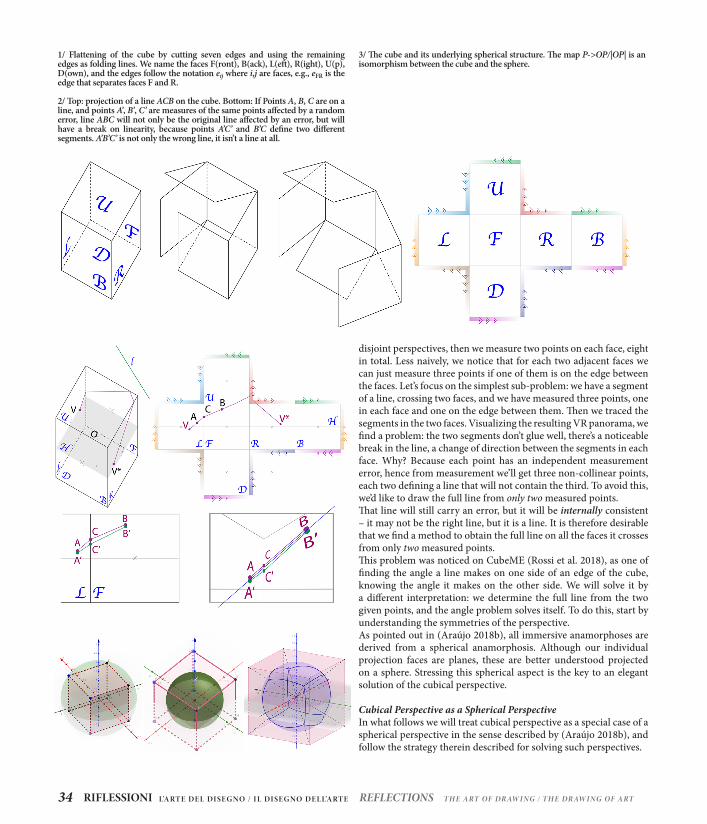
disjoint perspectives, then we measure two points on each face, eight in total. Less naively, we notice that for each two adjacent faces we can just measure three points if one of them is on the edge between the faces. Let’s focus on the simplest sub-problem: we have a segment of a line, crossing two faces, and we have measured three points, one in each face and one on the edge between them. Then we traced the segments in the two faces. Visualizing the resulting VR panorama, we find a problem: the two segments don’t glue well, there’s a noticeable break in the line, a change of direction between the segments in each face. Why? Because each point has an independent measurement error, hence from measurement we’ll get three non-collinear points, each two defining a line that will not contain the third. To avoid this, we’d like to draw the full line from only two measured points. That line will still carry an error, but it will be internally consistent – it may not be the right line, but it is a line. It is therefore desirable that we find a method to obtain the full line on all the faces it crosses from only two measured points.This problem was noticed on CubeME (Rossi et al. 2018), as one of finding the angle a line makes on one side of an edge of the cube, knowing the angle it makes on the other side. We will solve it by a different interpretation: we determine the full line from the two given points, and the angle problem solves itself. To do this, start by understanding the symmetries of the perspective.As pointed out in (Araújo 2018b), all immersive anamorphoses are derived from a spherical anamorphosis. Although our individual projection faces are planes, these are better understood projected on a sphere. Stressing this spherical aspect is the key to an elegant solution of the cubical perspective.
Cubical Perspective as a Spherical PerspectiveIn what follows we will treat cubical perspective as a special case of a spherical perspective in the sense described by (Araújo 2018b), and follow the strategy therein described for solving such perspectives.
1/ Flattening of the cube by cutting seven edges and using the remaining edges as folding lines. We name the faces F(ront), B(ack), L(eft), R(ight), U(p), D(own), and the edges follow the notation eij where i,j are faces, e.g., eFR is the edge that separates faces F and R.
3/ The cube and its underlying spherical structure. The map P->OP/|OP| is an isomorphism between the cube and the sphere.
2/ Top: projection of a line ACB on the cube. Bottom: If Points A, B, C are on a line, and points A’, B’, C’ are measures of the same points affected by a random error, line ABC will not only be the original line affected by an error, but will have a break on linearity, because points A’C’ and B’C define two different segments. A’B’C’ is not only the wrong line, it isn’t a line at all.
RIFLESSIONI34 REFLECTIONSL’A RT E DE L DI SE G NO / I L DI SE G NO DE L L’A RT E T H E A RT OF DR AW I NG / T H E DR AW I NG OF A RT

A spherical perspective can be described as a two-step process, the first step being the same for all such perspectives: a conical anamorphosis onto the sphere’s surface. The second step is a flattening of that spherical anamorphosis, often derived from a cartographic map of the sphere. This is the step that distinguishes
one spherical perspective from another. Cubic perspective is a spherical perspective in that sense. You just make the intermediate step of projecting from the sphere to the cube (figure 3) and then flatten the cube by opening it. The composition of these two actions is the flattening map. The importance of pointing out that
4/ Top: construction of a line given two points. Bottom: completing the geodesic and finding the line inside it.
PENSARE il disegno del pensiero/il pensiero del disegno 35THINKING the drawing of thought/ the thought of drawing

cubical perspective is a spherical perspective lies in the fact that the paper mentioned above specifies a clear strategy to solving any such perspective, and this strategy is then applicable to our case: if our surface (the cube) is isomorphic to the sphere by the central projection, then for our purposes it is a sphere. Then we solve its perspective by classifying and rendering the projection of the sphere’s geodesics onto the surface of the cube.Recall that the geodesics of a sphere are its great circles, i.e., the intersections of the sphere with the planes that pass through its center. Each spatial line defines a single plane through the center of the sphere, and that plane’s intersection with the sphere defines
a great circle. The anamorphic image of the line is just half of that great circle, i.e., a meridian, delimited by its two vanishing points. We spoke freely of tracing a line from two measured points, but do two points on the cube always determine a line image? What if they are in different faces? This becomes clear by thinking in terms of the sphere: two points on the cube determine two points on the sphere. And two points on the sphere determine a single plane through the origin (a great circle) if and only if those points are not antipodal (diametrically opposite) to each other. Hence, two non-antipodal points on the cube determine a single geodesic image on the cube. Then the line is defined by specifying a vanishing point in that
5/ Descriptive geometry construction of a 360º view from its geodesic projections on the cube
RIFLESSIONI36 REFLECTIONSL’A RT E DE L DI SE G NO / I L DI SE G NO DE L L’A RT E T H E A RT OF DR AW I NG / T H E DR AW I NG OF A RT

geodesic. The line image will be the meridian between this vanishing point and its antipode. Since we know that two non-antipodal points determine a geodesic image on the cube, all that remains is to construct it. That turns out to be an exercise in descriptive geometry. Let’s solve the example of the previous section (figure 2). We are given the images A and B of two points of a spatial line, on adjacent faces of the cube – for concreteness suppose A is on the left face and B on the front face of the cube. To find the full image of the line, we must find the image of the geodesic through A and B defined by plane π=AOB (note that we are identifying with the same notation corresponding points on the sphere and the cube, as well as geodesics).
Let eFL be the edge between the front and left faces and δFL the vertical plane through O and eFL, which defines another geodesic. The geodesics of π and δFL intersect in two antipodal points, one of which must project on the line containing eFL. Let that point be D. To find D, draw a top view beneath the front view (figure 4 top) and on it draw the projection of π and δFL. These intersect on a vertical line that contains a single point C of AB. To find the height of C, project line AB orthogonally on front view and intersect it with the front view of the vertical through C. Draw line OC. Where it intersects eFL, we find point D. We determine the geodesic on the two faces by drawing AD and DB to the edges of both faces to find points A’ and B’ of π. Finding the antipodes of these points we close the geodesic around the cube. To find the line itself we must know a vanishing point V.
6/ Frames from the VR rendering of the drawing of figure 5.
PENSARE il disegno del pensiero/il pensiero del disegno 37THINKING the drawing of thought/ the thought of drawing

Given V, find its antipode V*; the desired line is the section of the geodesic between V and V* (figure 4 bottom). Being able to draw, from only two measured points, segments that cross edges of the cube, we are now able to do all sorts of perspective constructions, such as finding centers of figures, segment multiplication, division, grid construction, etc. In figures 5, 6 and 8 we can see this construction in action.Are we done, then? Not yet. The construction above is only one of several possible cases. For instance, although point D falls necessarily in the line defined by edge eFL, it may fall outside of the edge itself, and in fact arbitrarily far from it. We don’t want a method that works in
principle but creates such difficulties for drawing, hence that case needs a different construction. Also, constructions will vary according to the relative positions of the faces in which the measured points are located and the number of faces touched by the geodesic. There are a number of such constructions, that the authors have now fully determined but need to classify in the most efficient manner. Their full description must wait for a later, lengthier publication.We finish by pointing out some important aspects of the relation between cubical perspective and other spherical perspectives. There are presently two total spherical perspectives that have been fully
7/ I n this construction point D is outside the edge of the two faces. A different construction is required to keep the drawing in the confines of the page.
RIFLESSIONI38 REFLECTIONSL’A RT E DE L DI SE G NO / I L DI SE G NO DE L L’A RT E T H E A RT OF DR AW I NG / T H E DR AW I NG OF A RT

8/ Application of the method to repeat a module in two different faces of the example from figure 5.
PENSARE il disegno del pensiero/il pensiero del disegno 39THINKING the drawing of thought/ the thought of drawing

solved in a manner adequate for handmade drawing. The first is the azimuthal equidistant perspective (Araújo 2018b) that generalizes Barre and Flocon’s fisheye spherical perspective (Barre & Flocon 1964). The second is equirectangular spherical perspective (Araújo 2018a). In both cases, images of a segment AB are never found from two arbitrary points. They require either the measurement of specially located points, or more than two points. This creates some difficulties for drawing. By contrast, cubical perspective, being a perspective that is spherical but not curvilinear, allows for a segment to be fully and easily determined by two arbitrary non-antipodal points. However (nothing ever comes for free) we must pay for this by doing some descriptive geometry work to cross the edges between faces and dealing with special cases that depend on the relative position of the points and faces. Another advantage of cubical perspective is the complete absence of blow-up singularities, of which there are one on azimuthal equidistant and two in equirectangular perspective. But in return we have a number of edge transitions which cause their own difficulties. It is all a game of give and take in spherical perspective and the user must choose wisely. As in cartography, it is good to have options, and a properly systematized cubical perspective is certainly be a useful option for the draughtsman to have.
ConclusionWe framed cubical perspective as a special case of spherical perspective and gave guidelines to solve it by studying its geodesics. We showed, in a special case, how a geodesic can be rendered from two arbitrary points, by using descriptive geometry methods and how this allows us to use classical perspective operations in the cubical case. We outlined the main aspects of a complete solution to the cubical perspective and discussed in what ways it compares with the other spherical perspectives currently available for handmade sketching.
AcknowledgementsAuthor A. B. Araújo was financially supported by Portuguese national funds through FCT, within project UID/Multi/04019/2013.
Notes* Department of Sciences and Technology, Universidade Aberta, and CIAC-UAb, Portugal. [email protected]** PhD Student in Environment, Design and Innovation, Università degli Studi della Campania “Luigi Vanvitelli”, Italy and in Digital Media Art, Universidade Aberta, Portugal [email protected]*** Department of Engineering, Università degli Studi della Campania “Luigi Vanvitelli”, Italy [email protected]
BibliographyAraújo António Bandeira, 2017. Anamorphosis: optical games with perspective’s playful parent. In: Proceedings of Recreational Mathematics Colloquium V - G4G (Europe) [online]. Lisboa: Associação Ludus. p. 71–86. from: http://hdl.handle.net/10400.2/6647Araújo António Bandeira, 2018a. Drawing Equirectangular VR Panoramas with Ruler, Compass, and Protractor. Journal of Science and Technology of the Arts. 3 April 2018. Vol. 10, no. 1, p. 15–27. https://doi.org/10.7559/citarj.v10i1.471Araújo António Bandeira, 2018b. Ruler, compass, and nail: constructing a total spherical perspective. Journal of Mathematics and the Arts. 3 July 2018. Vol. 12, no. 2–3, p. 144–169. https://doi.org/10.1080/17513472.2018.1469378Barba Salvatore, Fiorillo Fausta, Naddeo Alessandro, 2014. Tecniche di image editing: un possibile ‘work flow’ per le architetture prospettiche. In: Prospettive architettoniche. Conservazione digitale, divulgazione e studio. Graziano Mario Valenti. Rome, Italy: Sapienza Università Editrice. p. 871–886. Studi e Ricerche, 26. ISBN 978-88-98533-45-9Barre André, Flocon Albert, Bouligand Georges, 1967. La Perspective curviligne: de l’espace visuel à l’image construite. Paris: Flammarion Brown Matthew, Hartley Richard, Nister David, 2007. Minimal Solutions for Panoramic Stitching. In: 2007 IEEE Conference on Computer Vision and Pattern Recognition. 17 June 2007. p. 1–8. ISBN 1063-6919. https://doi.org/10.1109/CVPR.2007.383082Cabezos Bernal Pedro, Cisneros Vivó Juan, Soler Sanz Felipe, 2014. Anamorfosis, su historia y evolución. EGA Expresión Gráfica Arquitectónica [online]. 2014. Vol. Núm. 23 (2014). https://doi.org/10.4995/ega.2014.2184Greene Ned, 1986. Environment Mapping and Other Applications of World Projections. IEEE Computer Graphics and Applications. November 1986. Vol. 6, no. 11, p. 21–29. https://doi.org/10.1109/MCG.1986.276658Rossi Adriana, Barba Salvatore, Olivero Lucas Fabian, 2018a. “CubeME”, a variation for an immaterial rebuilding. In: Rappresentazione / Materiale / Immateriale. Drawing as (in)tangible representation [online]. Rome, Italy: Gangemi Editore International. 2018. p. 31–36. [Accessed 20 September 2018]. ISBN 978-88-492-3651-4. http://hdl.handle.net/11591/392282Rossi Adriana, Olivero Lucas Fabian, 2018b. Immersive models from analogical sketches applied to Solimene’s Factory. In: VII Congreso Internacional y XV Congreso Nacional de Expresión Gráfica en Ingeniería, Arquitectura y Carreras Afines. Río Cuarto, Argentina: UniRío Editora. September 2018. p. 55. ISBN 978-987-688-285-9. http://hdl.handle.net/11591/396733Rossi Adriana, 2017. Immersive high resoluttion photographs for cultural heritage. Adriana Rossi [Ed.]. Drawing/Disegno. Padova, Italy: libreriauniversitaria edizioni.it., 2017, vol. 2, 120 pp. ISBN 978-88-6292-855-7Rossi Daniele, 2018. Brand new: panorama. Continuous image to shape virtual reality. In: Rappresentazione / Materiale / Immateriale. Drawing as (in)tangible representation. Rome, Italy: Gangemi Editore International. 2018. p. 1389–1396. ISBN 978-88-492-3651-4Scolari Massimo, 1982. Ed. by Giorgio Ciucci & Massimo Scolari. Considerazioni e aforismi sul disegno. Rassegna. 1982. Vol. 9, p. 79–83. CIPIAVerweij Agnes, 2010. Perspective in a box. Nexus Network Journal. 1 April 2010. Vol. 12, no. 1, p. 47–62. https://doi.org/10.1007/s00004-010-0023-7Wong Tien-Tsin, Wan Liang, Leung Chil-Sing, 2007. Isocube: Exploiting the Cubemap Hardware. IEEE Transactions on Visualization & Computer Graphics. 2007. Vol. 13, no. 4, pp. 720–731. https://doi.org/10.1109/TVCG.2007.1020
RIFLESSIONI40 REFLECTIONSL’A RT E DE L DI SE G NO / I L DI SE G NO DE L L’A RT E T H E A RT OF DR AW I NG / T H E DR AW I NG OF A RT