Portable Survey Instruments - BHI Energy
110
Electric Power Research Institute, Inc. All rights reserved. Approved Rev: [Date] Portable Survey Instruments RP02.01
Transcript of Portable Survey Instruments - BHI Energy

Electric Power Research Institute, Inc. All rights reserved.
Approved Rev: [Date]
Portable Survey InstrumentsRP02.01

2Electric Power Research Institute, Inc. All rights reserved.
Standardized Task Evaluation Program
The Standardized Task Evaluation (STE) program
promotes a work-ready workforce through the
standardization of common tasks by defining the
knowledge and skills required to perform a given task.
Subject Matter Experts (SMEs) analyze the task and
generate lesson plans, knowledge examination, and
performance evaluation elements. These elements are
combined to create an STE package.
The Electric Power Research Institute (EPRI) facilitates
the development, oversees the quality, and
programmatically implements each STE. EPRI STE
members have access to these materials and permission
to implement these STEs in accordance with their site
training and qualification procedures.

3Electric Power Research Institute, Inc. All rights reserved.
10CFR20, Subpart F, Radiation Protection Program
Important Point
▪§20.1502 - The licensee shall monitor exposures to radiation and radioactive material at levels sufficient to demonstrate compliance with the occupational dose limits of this part.

4Electric Power Research Institute, Inc. All rights reserved.
Terminal Objective
▪When working as a RP technician at a U.S. nuclear utility,
the individual will be able to properly select, setup, and use
portable survey instruments in order to support worker
activities in a radiological control area in accordance with the
standards of NISP-RP-02.01, Portable Survey Instruments.

5Electric Power Research Institute, Inc. All rights reserved.
Enabling Objectives
1.) Describe the theory of operation for the following detectors:
– Gas Filled
GM
Proportional Counter
Ion Chamber
– Scintillation
Zinc Sulfide
Plastic Scintillation
Nal
CsI
Dual Scintillation
– Solid State

6Electric Power Research Institute, Inc. All rights reserved.
Enabling Objectives
2.) Identify the correct instrument to use based on the type of
survey to be performed
3.) Describe the preoperational checks required for portable
instruments:
Visual
Calibration check
Battery check
Source check
Available scales
Documentation
4.) Identify the risk of an off-scale reading high due to the potential
for over-ranging conditions.

7Electric Power Research Institute, Inc. All rights reserved.
Enabling Objectives
5.) Describe conditions that might affect survey instrument
response.
6.) Describe the operational characteristics of:
Gas filled detectors
Scintillation detectors
Solid State detectors
7.) Given a correction factor, calculate:
Ion Chamber, Beta/Gamma readings
GM tube, cpm to dpm

8Electric Power Research Institute, Inc. All rights reserved.
Gas Filled Detectors

9Electric Power Research Institute, Inc. All rights reserved.
Gas Filled Detector

10Electric Power Research Institute, Inc. All rights reserved.
Radiation Detection – Gas Filled Detector
▪How is radiation detection
possible?
▪Due to the ability of
radiation to produce
ionization.
▪The detector is used to
indicate the presence of
radiation.
▪A current measuring device
or meter is used to indicate
the intensity of the
radiation.

11Electric Power Research Institute, Inc. All rights reserved.
Radiation Detection – Gas Filled Detector
▪Factors affecting pulse size in gas filled
detectors.
–Type of radiation
–Energy of radiation
–Applied voltage
–Source strength
–Distance from the source
–Medium between the source and detector.

12Electric Power Research Institute, Inc. All rights reserved.
Six Region Curve

13Electric Power Research Institute, Inc. All rights reserved.
Six Region Curve
▪Pulse magnitude and duration
▪Radiation and Voltage will affect output
▪Ion chamber pulse and/or current output vs.
detector voltage input.
▪Known as the six region curve or the gas
amplification curve.

14Electric Power Research Institute, Inc. All rights reserved.
The radiation field must be unchanging or the curve will shift up or
down.
The amount of applied voltage, the type of gas, and the energy
level of the measured radiation all play a part in the pulse
magnitude and duration measured at the output of the gas filled
detector.
The more ionizing the radiation or the higher the applied voltage to
the detector, the higher the pulse or current seen on the output.
Ion chamber pulse and/or current output vs. detector voltage input.
Known as the six region curve or the gas amplification curve.
Six Region Curve

15Electric Power Research Institute, Inc. All rights reserved.
Six Region Curve
▪ If a gas filled chamber is set in a radiation field of
unchanging intensity and the applied voltage is raised from
zero to some high value, the gas amplification characteristic
curve for a gas filled detector results.

16Electric Power Research Institute, Inc. All rights reserved.
Six Region Curve – Recombination
▪Zero voltage – no ionization
▪Not enough applied voltage
to attract all ion pairs
produced
▪As voltage increase,
ionization occurs, but some
ion pairs recombine before
reaching electrodes
▪NOT USED IN RADIATION
DETECTORS

17Electric Power Research Institute, Inc. All rights reserved.
Six Region Curve – Ionization Chamber
One to one ratio ▪ 100% of ion pairs produced are
collected
▪ Output signal from detector is
directly proportional to the
amount of radiation entering the
detector – ideal for dose rate
measurements
Advantages of detectors operating in
this regions are:
• Accuracy
• Response proportional to dose rate
• Less regulated power supply needed
No gas amplification for creating
secondary ion events– all primary ion
pairs.

18Electric Power Research Institute, Inc. All rights reserved.
Six Region Curve – Ionization Chamber
Beta Radiation Gamma Radiation
▪Beta particles are
charged and can be
measured directly
provided the particle
passes through the
shielding of the chamber
wall (which it normally
cannot).
▪A window on some
detectors allows beta
particles to enter, this is
shown on slide 94.
▪Detectors rely on fill gas
molecules and various
gamma interactions with
matter to provide ions
inside chamber.
▪Gamma interactions
– Photo-electric effect
– Pair Production
– Compton Scattering

19Electric Power Research Institute, Inc. All rights reserved.
Six Region Curve – Ionization Chamber
▪Pulse size is dependent on radiation energy and type
▪Most accurate region because every ion pair created is
collected.
▪Insensitive to low radiation levels, Generally ionization
chamber detectors cannot detect radiation level <2
mr/hr. The amount of current produced is small so a
large amount of amplification is required.
▪Used for stay time and dose assessment
measurements.
▪Best for measuring high levels of radiation.
20Electric Power Research Institute, Inc. All rights reserved.
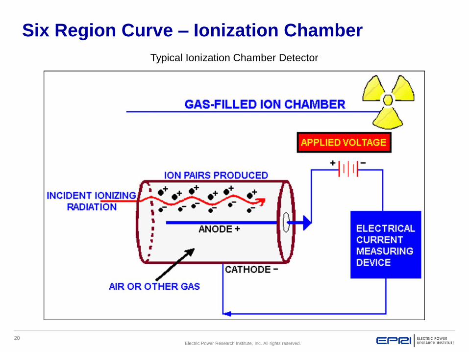
Six Region Curve – Ionization Chamber
Typical Ionization Chamber Detector

21Electric Power Research Institute, Inc. All rights reserved.
Six Region Curve – Ionization Chamber
Sequence of events of the previous slide:
1.Radiation passes through the chamber.
2.The radiation interacts with an atom of the fill gas.
3.The radiation gives up some or all of its energy to the gas atom.
4.The excited gas atom releases one of its orbital electrons.
5.The electric field causes the electron to drift toward the center
(+) electrode (anode).
6.The now positively charged gas ion drifts toward the (-) electrode
(cathode).
7.The electron and positively charged atom are collected on the
electrodes and produce an electric current which flows through
the anode to the electronic metering circuit.

22Electric Power Research Institute, Inc. All rights reserved.
Six Region Curve – Proportional Counter
Where gas amplification starts
▪ Initial ionization occurs
▪Amount of signal
amplification is the “gas
amplification factor”
▪Detector circuitry measures
pulses – more energetic the
radiation detected, the
higher the pulse

23Electric Power Research Institute, Inc. All rights reserved.
This region can be used for radiation discrimination of alpha and beta
and dose rate measurements. Proportional counters must have a
stable power supply because they are voltage dependent.
Examples:
• Tennelec changes voltage for counting smears for alpha and beta.
• Personnel contamination monitors (PCMs) can be used with a circuit
that counts pulses and can discriminate types of radiation based on
pulse heights.
Some instruments operating in the proportional region can be used to
measure beta, gamma and alpha radiations simultaneously because
the numbers of ions created by the beta, gamma and alpha are
significantly different, depending on the voltage.
Six Region Curve – Proportional Counter

24Electric Power Research Institute, Inc. All rights reserved.
Six Region Curve – Proportional Counter
▪ Uses
– Quantifying alpha and beta activity
– Neutron detection
– X-ray spectroscopy.
▪ The pulses produced are larger than those produced by an ion chamber
▪ Unlike the situation in a GM detector (we’ll see later), the pulse size
reflects the energy deposited by the incident radiation in the detector
gas. As such, it is possible to distinguish the larger pulses produced
by alpha particles from the smaller pulses produced by betas or
gamma rays. By using a “voltage window” the pulse received may
be included or excluded based on whether it is in the “window”.
▪ The pulses produced by a proportional counter are larger than those
produced by an ion chamber. This means that the proportional
counter is more conveniently operated in the pulse mode (ion
chambers usually operate in the current mode).
25Electric Power Research Institute, Inc. All rights reserved.
Six Region Curve – Proportional Counter
▪The size of the pulse in a proportional counter depends
on two things:
–Operating Voltage. The higher the operating voltage,
the larger each avalanche becomes and the larger
the pulse (must have a stable voltage supply).
–Energy Deposited in Detector Gas. The greater the
energy deposited in the detector gas by an incident
particle of radiation, the larger the number of primary
ion pairs, the larger the number of avalanches, and
the larger the pulse.

26Electric Power Research Institute, Inc. All rights reserved.
Six Region Curve – Proportional Counter
This diagram shows a charged particle traversing the detector gas. Four
primary ion pairs (and four resulting avalanches) are produced. It is usually
the case that many more ion pairs are produced by incident radiation than
the four shown here. Keep in mind that the four avalanches contribute to
a single pulse.

27Electric Power Research Institute, Inc. All rights reserved.
This diagram shows the Townsend Avalanche. In a proportional counter, many
electrons (10 - 10,000) reach the anode for each primary ion pair produced in the
gas. The reason is that the electron of each primary ion pair creates further
"secondary" ion pairs as it gets close to the anode. These secondary ion pairs are
produced in what is called an avalanche.
Six Region Curve – Proportional Counter

28Electric Power Research Institute, Inc. All rights reserved.
Instruments operating in the proportional region rely on primary and
secondary ions to create a current sufficient to be useful in measuring
radiation.
Advantages
• Good discrimination
• Detector can be used with a circuit that counts pulses and can
discriminate types of radiation based on pulse heights
• Good sensitivity
• Fast response time
Disadvantages
• Requires highly regulated power supply (voltage dependent)
• Fill gas is a compressed gas that is more expensive than the air that fills
an air filled ion chamber.
Six Region Curve – Proportional Counter

29Electric Power Research Institute, Inc. All rights reserved.
This region can also be used for neutron monitoring. Typically through 2
methods: fission of U-235 and absorption of B-10.
In the following animation, the neutron fission process in the detector only
shows one positively charge fission product and one negatively charged
electron being released inside the chamber.
In reality, there are two fission products released with each one having
multiple positive charges. There would also be multiple negative charges
released as a result. This creates a much larger pulse than a gamma
interaction with the gas in the detector. The smaller gamma pulses can be
discriminated with the external circuitry so that only neutrons are
detected.
Plant use: incore or excore neutron detectors (fission chamber detector)
Note that the next slide shows the initial ionization, but also the secondary
ionizations produced in the fill gas. This is caused by in increase in the
detector applied voltage.
Six Region Curve – Proportional Counter

30Electric Power Research Institute, Inc. All rights reserved.
Fission Chamber
CATHODE -U3O8 COATING (95% ENRICHED U-235)
ANODE +
NEUTRON
FISSION PRODUCT
ELECTRON
+--

31Electric Power Research Institute, Inc. All rights reserved.
This is measured with a proportional (region) counter. Only the Boron-
10 reacts with the neutron to produce the Li, alpha, and electrons. The
alpha causes ionization of the gas and the subsequent current pulse in
the detector external circuitry. The alpha is then measured. Example:
Rem Ball.
A series of current pulses are counted to determine the radiation level.
The amount of current produced in this region is amplified through a
process known as gas amplification. For each initial ion pair produced
in the detector, 1 million (106) secondary ionizations are produced.
Six Region Curve – Proportional Counter

32Electric Power Research Institute, Inc. All rights reserved.
Gas amplification increases the detector’s sensitivity to low level radiation. The gas
amplification factor (GAF) for a detector is constant at a given applied voltage.
Variations in applied voltage cause variations in GAF, therefore, a stable voltage
supply is required.
Pulse size is dependent on radiation energy and type, therefore, radiation
discrimination can take place.
Instruments operated in this region can be used for Stay Time and Dose
Assessment Measurements.
Radiation discrimination is accomplished electronically using a pulse height
analyzer (PHA).
Neutron detectors use some form of boron 10 (Bf3= Boron trifluoride) because
neutrons would not otherwise interact in the detector sufficiently to create a
measurable signal. The next slide depicts this interaction.
Six Region Curve – Proportional Counter

33Electric Power Research Institute, Inc. All rights reserved.
BF3 Proportional Detector
5B10 + 0n
15B
113Li7 + 2
4 ++ + 2e-

34Electric Power Research Institute, Inc. All rights reserved.
Six Region Curve – Proportional Detector

35Electric Power Research Institute, Inc. All rights reserved.
Six Region Curve – Proportional Detector

36Electric Power Research Institute, Inc. All rights reserved.
Six Region Curve – Proportional Detector

37Electric Power Research Institute, Inc. All rights reserved.
Six Region Curve – Limited Proportional
▪A transitional region to the
Geiger-Mueller region.
▪NOT USED IN RADIATION
DETECTION

38Electric Power Research Institute, Inc. All rights reserved.
Six Region Curve – Geiger-Mueller
▪G-M counters produce
the largest signal from an
ionizing event
▪ Ions are moving with
such energy that entire
tube is flooded with
positive and negative
ions
▪The result is referred to
as an avalanche and is
one pulse
▪Pulses are a count rate

39Electric Power Research Institute, Inc. All rights reserved.
Because of this large gas amplification region (GAF), the pulse size is
the same for every event. This prevents any ability to discriminate
against different types of radiation.
Examples: Friskers, Telepoles
Avalanching causing a pulse that is detected in GM Region.
A series of current pulses are counted to determine the radiation level.
The large gas amplification field (GAF) in this region makes this type of
detector ideally suited for low level radiation detection. For each initial
ion pair produced in the detector, 1 billion (109) secondary ionizations
are produced. Because the large GAF may lead to continuous
discharge inside the detector, quenching materials are added to the gas
to prevent it from occurring. The pulse size in this region is constant
regardless of the type of energy of the radiation, therefore, the ability to
discriminate against the different types of radiation is lost. Because the
response of the detectors in this region is dependent on the energy
they are calibrated to, they cannot be used for stay time or dose
assessment calculation.
Six Region Curve – Geiger-Mueller

40Electric Power Research Institute, Inc. All rights reserved.
Six Region Curve – Geiger-Mueller
▪Beta or alpha particles ionize the fill gas directly
▪Gamma and x-rays ionize the gas indirectly by interacting
with the metal wall of the GM (via the photoelectric effect,
Compton scattering or pair production) in such a way that
an electron is "knocked" off the inner wall of the detector.
▪This electron then ionizes the gas inside the tube.
▪ It is true that gamma rays or x-rays might interact with the
fill gas rather than the wall, but this is less probable except
for very low energy photons.

41Electric Power Research Institute, Inc. All rights reserved.
Six Region Curve – Geiger-Mueller

42Electric Power Research Institute, Inc. All rights reserved.
Six Region Curve – Geiger-Mueller
▪At the high voltages associated with the Geiger-Mueller
Region, the avalanche created by a single primary
electron leads to the creation of other "secondary"
avalanches, and so many of these "secondary"
avalanches occur that they completely envelop the
anode. The pulse eventually shuts itself down when
the accumulation of positive ions around the anode
reduces the strength of the electric field below that
required for continued propagation.

43Electric Power Research Institute, Inc. All rights reserved.
The electric field created by the potential difference between the
anode and cathode causes the negative member (electron) of
each ion pair to move to the anode while the positively charged
gas atom or molecule is drawn to the cathode. As the electrons of
the primary ion pairs move towards the anode, they gain kinetic
energy (and lose potential energy). If the electric field in the
chamber is of sufficient strength (approximately 106 V/m) these
electrons gain enough kinetic energy to ionize the gas and create
secondary ion pairs. The electrons produced in these secondary
ion pairs, along with the primary electrons, continue to gain
energy as they move towards the anode, and as they do, they
produce more and more ionizations. The result is that each
electron from a primary ion pair produces a cascade or avalanche
of ion pairs (Townsend avalanche).
Six Region Curve – Geiger-Mueller

44Electric Power Research Institute, Inc. All rights reserved.
Six Region Curve – Geiger-Mueller
The mechanism by which a single avalanche can eventually envelope
the entire anode involves the fact that any avalanche not only
involves the ionization of gas molecules, it also involves the excitation
of gas molecules. The subsequent de-excitation of the excited
molecules results in the emission of UV photons. If enough of these
photons are produced, some will be absorbed by the gas molecules
via the photoelectric effect. This leads to further ionization of the gas
and the formation of a second avalanche. For all practical
purposes, the multiple avalanches are produced at the same
time - only one pulse results. The following diagram above shows
how a single avalanche can spread along the anode via the emission
of UV photons.

45Electric Power Research Institute, Inc. All rights reserved.
Six Region Curve – Geiger-Mueller

46Electric Power Research Institute, Inc. All rights reserved.
Six Region Curve – Geiger-Mueller
Definitions of Dead Time, Recovery Time, and
Resolving Time

47Electric Power Research Institute, Inc. All rights reserved.
Six Region Curve – Geiger-Mueller
Dead time is the time period when new ionizing events will not
be detected.
Recovery time is the time that the voltage gradient inside the
detector is being restored.
Resolving time is the time period between two separate
ionizing events so that both are detected.

48Electric Power Research Institute, Inc. All rights reserved.
Six Region Curve – Geiger-Mueller
GM detectors experience the longest dead times due to their
high gas amplification factor (109 ). Dead times for GM
instruments can be from 200 to 300 microseconds whereas the
dead time for proportional detectors average about 5
microseconds due to their lower gas amp factors (106) . Ion
chambers are not affected by dead time due to their low
voltage which does not allow for gas amplification.
Because of long dead times in G-M detectors, they can
saturate in high fields of radiation.
• Saturation is when a G-M detector reads low in a high
field of radiation.
• Saturation in a G-M detector is hard to detect unless the
meter’s operator sees it occur.

49Electric Power Research Institute, Inc. All rights reserved.
Six Region Curve – Geiger-Mueller

50Electric Power Research Institute, Inc. All rights reserved.
Six Region Curve – Geiger-Mueller

51Electric Power Research Institute, Inc. All rights reserved.
Six Region Curve – Geiger-Mueller

52Electric Power Research Institute, Inc. All rights reserved.
Advantages of these types of detectors:
• Unaffected by atmospheric temperature or pressure
• Magnitude of output pulse
• Less regulated power supply
• Greater sensitivity (for comparable size)
Disadvantages of these types of detectors:
• Does not measure true dose (Detector response unrelated to
energy deposited)
• Large dead time
• Non-discriminating
• If saturated - detectors fail down scale if a special circuit is not
present to prevent a down-scale failure
• Over response to low energy gamma energies (~70 kev)
• Over response to high gamma energies (i.e. N-16 ~6 Mev)
Six Region Curve – Geiger-Mueller

53Electric Power Research Institute, Inc. All rights reserved.
Scintillation Detectors

54Electric Power Research Institute, Inc. All rights reserved.
Scintillation Detectors and semi-conductor detectors are not gas filled and do not operate anywhere on the Gas amplification curve.
1. Scintillation detectors use materials capable of changing the energy of ionizing radiation to visible light via the excitation process.
2. The intensity of the light is proportional to the amount of radiation present.
a. The light is measured with a photomultiplier tube to determine the level of radioactivity or radiation level.
b. Different types of phosphors and material are used for detecting the different types of radiation.
1) ZnS- Zinc Sulfide crystals for alpha detection
2) Plastic Scintillators for beta detection
3) NaI Sodium Iodide for gamma detection
4) CsI- Cesium Iodide for gamma detection
Scintillation Detectors

55Electric Power Research Institute, Inc. All rights reserved.
Scintillation Detectors
▪ Ionizing radiation interacts with phosphor crystalline
material to produce light called scintillation.
▪Alpha, beta, and gamma scintillators.
▪A photo multiplier tube used to convert this light to an
electrical pulse.
▪A major advantage of the scintillation counter over a gas-
filled detector is the much higher counting efficiency for
gamma radiation.
▪Dual Scintillation Detectors contain a thin plastic scintillator with a coating of ZnS, which are effective in surveying both alpha and beta particles at the same time.

56Electric Power Research Institute, Inc. All rights reserved.
The detector principle dose does not involve gas amplification.
Different phosphor materials are sensitive to different types of
radiation.
Examples of instruments: Fast Scan whole body counter, SAM-11
(plastic scintillators) refers to a scintillating material in which the
primary fluorescent emitter called a fluor is suspended in the base, a
solid polymer matrix.
The advantages of plastic scintillators include fairly high light output
and a relatively quick signal, with a decay time of 2–4 nanoseconds,
but perhaps the biggest advantage of plastic scintillators is their ability
to be shaped, through the use of molds or other means, into almost
any desired form with what is often a high degree of durability
Scintillation Detectors

57Electric Power Research Institute, Inc. All rights reserved.
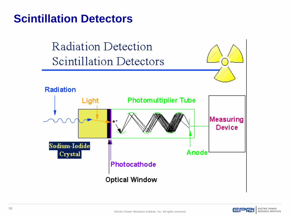
Sequence of events in the following slide (alpha, beta and gamma)
1.Radiation enters the crystal material, Radiation interacts with a phosphor atom
2.The phosphor atom gives off a flash of light
3.Light is transmitted through the crystal (also reflected off walls of crystal casing) and collected at the photo cathode of the photo-multiplier tube.
4.Photo cathode converts light into electrons
5.Electron is emitted and is aimed toward the amplifying dynodes.
6.Dynodes, in the Photo multiplier tube, then attract and multiply the number of electrons emitted (from the previous dynode or source).
7.External circuit allows these electrons to be measured or counted.
Scintillation Detectors
58Electric Power Research Institute, Inc. All rights reserved.
Scintillation Detectors

59Electric Power Research Institute, Inc. All rights reserved.
Scintillation Detector
Examples of Scintillation Detectors:
Fast Scan Whole Body Counter
SAM 11
Bicron Analyst
ASP with a 50cm or 100cm scintillation probe
Bicron micro-rem

60Electric Power Research Institute, Inc. All rights reserved.
Scintillation Detectors
▪Used to detect alpha, beta, and gamma radiation
depending on the crystal used.
▪Contamination detectors (especially alpha).
▪Low level radiation and natural background checks.
Advantages
▪ Detects low level radiation
common to loose surface and
fixed contamination
▪ Readily portable
▪ Can discriminate energy of
gamma
Disadvantages
▪ Light sensitive
▪ Easily damaged
▪ Temperature sensitive

61Electric Power Research Institute, Inc. All rights reserved.
Semiconductor Detectors

62Electric Power Research Institute, Inc. All rights reserved.
Semiconductor Detector

63Electric Power Research Institute, Inc. All rights reserved.
Semiconductor Detector

64Electric Power Research Institute, Inc. All rights reserved.
Semiconductor Detector

65Electric Power Research Institute, Inc. All rights reserved.
Semiconductor Detector

66Electric Power Research Institute, Inc. All rights reserved.
Semiconductor Detector
There is no energy
gap to cross in order
to reach the
conduction band.

67Electric Power Research Institute, Inc. All rights reserved.
Semiconductor Detector

68Electric Power Research Institute, Inc. All rights reserved.
Semiconductor Detector

69Electric Power Research Institute, Inc. All rights reserved.
Semiconductor Detector

70Electric Power Research Institute, Inc. All rights reserved.
Semiconductor Detector
▪3 electrical classes of
material
– Insulator
– Semiconductor
– Conductor
▪Semiconductor detector
uses the semiconductor
type material
▪Examples: Electronic
dosimeters and gamma
spectroscopy equipment
71Electric Power Research Institute, Inc. All rights reserved.
Another way of looking at this is like a spark plug. Insulator
– gap so far apart that the spark wouldn’t reach. Semi-
conductor – gap just right for good spark. Conductor –
electrons move back and forth. In atoms, electrons are
divided into energy levels which tend to form bands. The
highest, filled energy level at which electrons occupy is called
the valence band and the first level above the valence band
is known as the conduction band. The valence electrons do
not participate in conduction.
Semiconductor detectors act like gas-filled ionization
detectors. The semiconductor is usually silicon or
germanium.
Semiconductor Detector

72Electric Power Research Institute, Inc. All rights reserved.
Semiconductor Detector
Sequence of events:
1.Electron-hole pairs2.Radiation interacts with crystal.3.Electron is raised from Valence band
to Conductive band.4.”Missing” electron creates a “hole-
pair” in the Valence band (similar to electron pair in gas filled detector).
5.In an electric field the “hole-pair” moves toward cathode and electrons moved toward anode to cause current flow/pulse.
Note: Continued on next slide.
Only a small amount of energy is required to create an electron-hole pair .

73Electric Power Research Institute, Inc. All rights reserved.
6. Crystal must have a center depletion region formed by use of very high purity materials.
7. Ionizing radiation interacts in center depletion region, leaving “holes”.
8. Center depletion region acts as a solid “fill gas” and “electron hole pairs” are equivalent to ion pairs in a gas filled detector.
9. Under the influence of an electric field, electrons and holes travel to the electrodes, where they result in a pulse that can be measured.
Semiconductor Detector

74Electric Power Research Institute, Inc. All rights reserved.
Semiconductor Detector
▪ Semi-Conductors have a major advantage over scintillation due to better energy resolution (especially for alpha and beta), greater durability and easier of transport.
▪ There current drawback is the higher cost of Semi-Conductors. As the cost to produce Semi-Conductors goes down, their will be a greater increase in their use in the field.
▪ They are cooled by liquid nitrogen in order to reduce the thermal generation of charge carriers (thus reverse leakage current) to an acceptable level. Otherwise, leakage current induced noise destroys the energy resolution of the germanium detector.

75Electric Power Research Institute, Inc. All rights reserved.
Advantages
▪Good energy
resolution
▪Unique energy peaks
▪Durability
▪Ease of transport
Disadvantages
▪High cost
▪The detector needs to
be cooled
Semiconductor Detector

76Electric Power Research Institute, Inc. All rights reserved.
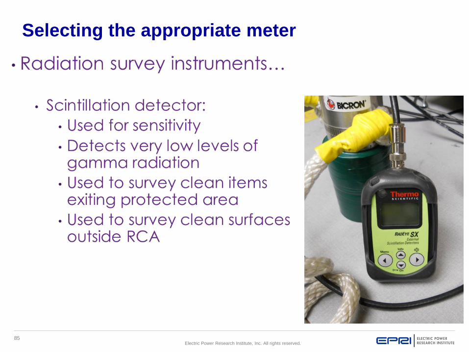
Selecting the appropriate meter
▪Determining the appropriate instrument for performance of
radiation surveys under various conditions is based on:
– Expected Radiation Type(s) – i.e. General area walkways,
Systems with RCS, charging water, gas lines, Containment entries,
Fuel Pool.
– Expected dose rates – Initial postings, previous survey maps of
the area, RWP.
– Environmental conditions – Temperature, noise, lighting,
clearance of mobility (how cluttered with pipes and material in the
area).
A pre-job review of area radiological conditions should
update you on expected environment of the area to be
surveyed.

77Electric Power Research Institute, Inc. All rights reserved.
Selecting the appropriate meter
▪Many factors go into choosing the best
instrument for a particular survey:
• Contamination or radiation survey
• Expected radiation type(s)
• Expected dose rate
• Environmental conditions
• Location of survey
• Reason for survey

78Electric Power Research Institute, Inc. All rights reserved.
Selecting the appropriate meter

79Electric Power Research Institute, Inc. All rights reserved.
Selecting the appropriate meter

80Electric Power Research Institute, Inc. All rights reserved.
Selecting the appropriate meter

81Electric Power Research Institute, Inc. All rights reserved.
Selecting the appropriate meter

82Electric Power Research Institute, Inc. All rights reserved.
Selecting the appropriate meter

83Electric Power Research Institute, Inc. All rights reserved.
Selecting the appropriate meter

84Electric Power Research Institute, Inc. All rights reserved.
Selecting the appropriate meter
85Electric Power Research Institute, Inc. All rights reserved.
Selecting the appropriate meter

86Electric Power Research Institute, Inc. All rights reserved.
Selecting the appropriate meter

87Electric Power Research Institute, Inc. All rights reserved.
Operability Checks
▪Physical condition
▪Meter zero
▪Calibration date
▪Battery check
▪Source check response
▪Available Scales
▪Documentation

88Electric Power Research Institute, Inc. All rights reserved.
Physical Condition: Ensures all switches, meter
movement and detector, including the detector cable,
if applicable, are in good condition.
Meter zero: Some meters allow for a physical
adjustment of the needle zero.
There is a mechanical zero located in front of the
meter handle. This is not to be adjusted as part of
the daily performance check.
Calibration date: Check the calibration sticker for
verification of calibration within the last six months.
Battery check: Ensure the batteries are within the
battery okay range, if batteries are below the battery
okay range, replace the batteries prior to performing
any work.
Note: Continued on the next slide.
Operability Checks

89Electric Power Research Institute, Inc. All rights reserved.
Source check: Ensures the meter responds to the source
correctly. Permissible tolerance is + 20 percent.
Available scales: Depending on the radiation dose field to be
entered would depend upon the available scales required. Ensure
you obtain the proper meter for the radiation field to be entered.
If not immediately signed out for use, instruments that pass pre-
operational checks should be turned off and placed in an area or
location identified for storage of equipment “ready for use”. The
instruments are turned off to conserve the batteries used to power
the detector and those used for powering components such as
the electrical signal amplifiers. If the battery power indicator
shows low on the instrument, then replace all the batteries to
ensure adequate power is available to all meter components.
Operability Checks

90Electric Power Research Institute, Inc. All rights reserved.
Documentation: Site specific procedures give direction on
sources to use and anticipated instrument responses.
Perform checks in accordance with procedure; then
DOCUMENT the results. Follow procedure instructions for
instruments that fail pre-operational checks. Defective
instruments or those tagged as out of service should be
segregated from operational instruments to prevent use of
inoperative equipment.
Operability Checks

91Electric Power Research Institute, Inc. All rights reserved.
Identify the Risk
The radiation dose field one would be entering would determine the
type of meter to be used. Ensure you obtain the proper meter for the
expected radiation field to be entered.
An example would be, entering a high gamma
field with a tele-pole on a low range setting. The
instrument could become saturated and read
incorrectly leaving you in a higher dose field
causing you a higher than anticipated dose. While
a GM detector is great for reading gammas and is
very accurate it is not always the best choice as
an only meter. A good practice is to enter with 2
separate instruments such as an ion chamber and
a tele-pole at the higher setting. The ion chamber
may take a little longer to respond but it will not
saturate as a GM could.

92Electric Power Research Institute, Inc. All rights reserved.
Geotropism: The effect of gravity on the meter reading
depending on how it is held.
Atmospheric pressure: Most often seen on
containment entries for certain meters.
High humidity: May inhibit gas interaction particularly in
Ion Chambers. Ion chambers have an internal desiccant
to remove moisture.
Mixed radiation fields: Neutron interaction can effect
proportional counter readings for Alpha (not commonly a
problem).
Noble gas atmospheres: Can saturate Ion Chambers.
Ion chambers (Ro2 & Ro2A) when saturated will render a
false high reading.
Extreme temperatures: Can adversely effect meter’s
circuity.
Off-scale reading: Improper scale, meter
contamination, GM saturation.
Radiofrequency interference: High voltage areas that
cause EMF. Electromagnetic Frequency (EMF) that can
cause interference with survey instruments are welding
units, magnets, walkie-talkies, high voltage lines.
Conditions that may effect survey instrument response

93Electric Power Research Institute, Inc. All rights reserved.
• Probe contamination – go to a low background area to verify
probe contamination or interference from other types of
radiation.
• Distance between the probe and surface being monitored –
hold the detector ~ ¼ inch from the surface.
• Climatic conditions – humidity and atmospheric pressure will
affect the response of the detector, especially a gas proportional
counter detector.
• Instrument repair and calibration – ensure the instrument is in
good condition and has a current calibration. (PROBE and
METER CALIBRATED TOGETHER)
• Type of surface and overlying material – irregular surfaces
may prevent holding the detector within ¼ inch of the surface
being monitored. Liquids or other materials on the surface being
monitored will absorb the alpha particles and prevent their
detection.
• Monitoring technique – the detector must be moved slowly
over the surface being monitored to give the meter time to
respond.
Factors Affecting Alpha Survey Results

94Electric Power Research Institute, Inc. All rights reserved.
Operational Characteristics/Correction FactorsThere are various types of Ion Chamber
meters. (RSO-5, RSO-50, Fluke 451B to
name a few) These meters are vented to air,
some have a plastic body while others may
have a metal body. They will have a Beta
window as shown (to the right) to detect
Betas, however each meter will have a
correction factor.
Determine the gamma dose rate by holding
the instrument in a steady position with the
window closed and allowing the readout to
stabilize.
Determine the beta dose rate by obtaining an
open window readings with the instrument in
the same position. Apply the following
calculation:
To obtain a Beta reading take the open
window reading and subtract the closed
window reading and then multiply the
difference of the two numbers by the beta
correction factor. The meter to the left uses a
beta correction factor of 4.
95Electric Power Research Institute, Inc. All rights reserved.
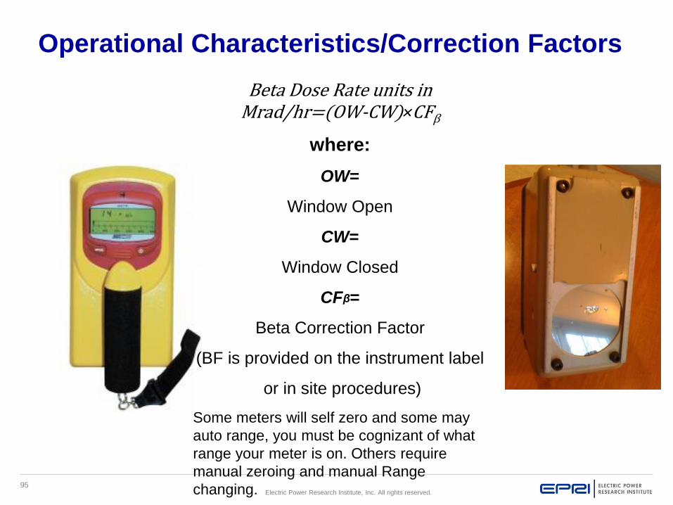
Operational Characteristics/Correction Factors
Beta Dose Rate units in Mrad/hr=(OW-CW)×CFβ
where:
OW=
Window Open
CW=
Window Closed
CFβ=
Beta Correction Factor
(BF is provided on the instrument label
or in site procedures)
Some meters will self zero and some may
auto range, you must be cognizant of what
range your meter is on. Others require
manual zeroing and manual Range
changing.

96Electric Power Research Institute, Inc. All rights reserved.
Knowledge check
You have an open reading on a valve of 10
mr/h and a closed window reading of 20
mr/h, using a correction factor of 4 what is
your Mrad/hr reading? Do your math and
give it to the Instructor for discussion.

97Electric Power Research Institute, Inc. All rights reserved.
The Telepole or (Extender) has an extendable probe for surveying
inaccessible or high dose areas. This meter is very sensitive but is prone to
saturation in very high dose rate areas. Keep in mind that if one is using a
GM detector (Telepole) to gain a reading on a specific location that reading
will always be higher than that of an ion chamber due to the size of the
detector and decreased distance from the source. Keep in mind this
detector cannot discriminate between Beta/Gamma
GM Detector(s)

98Electric Power Research Institute, Inc. All rights reserved.
Six Region Curve – Geiger-Mueller Gamma
Energy Response Curve
As can be noted in the graph above, the "thin wall" style GM tube with an 80 mg/sq. cm
window provides excellent transmission for low energy photons below 100 keV. However,
relative to Cs-l37 it does over-respond by nearly a factor of 13 at 70 keV. This results from
the high photon influence being transmitted through the cathode wall, a high interaction
probability, and the subsequent discharge events being counted. In the intermediate
energies the response is relatively flat, but does begin to increase slightly above 1 MeV.
The latter is due to the increase in number of secondary charged particles from pair
production.

99Electric Power Research Institute, Inc. All rights reserved.
Six Region Curve – Geiger-Mueller Gamma
Energy response curve
Over-response below about 200 keV may be reduced by adding a thin layer filter of high
atomic number metal over the tube with an appropriate open area. This effectively
attenuates a portion of the low energy photon influence. With proper engineering, one can
easily obtain a 20% response from 50 keV to 1.25 MeV using a "thin wall" GM tube and
energy compensation filter. However, the high atomic number filter actually causes an
increased over-response in the 6 MeV range compared to the bare tube. This is no doubt
due to energetic secondaries produced in the energy compensation filter, passing through
the GM tube cathode wall and causing a discharge.
100Electric Power Research Institute, Inc. All rights reserved.
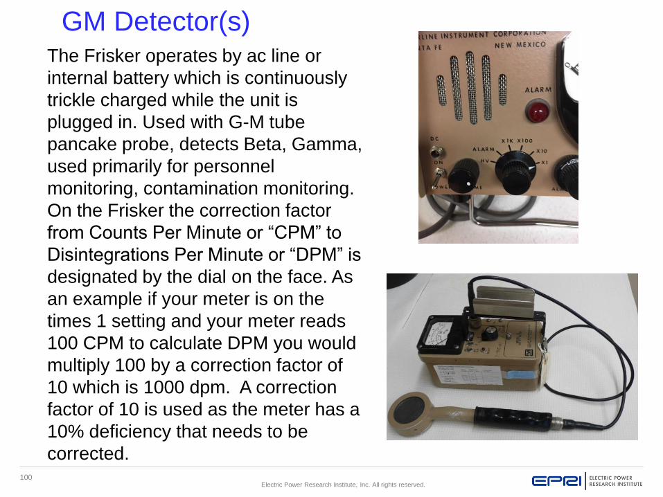
The Frisker operates by ac line or
internal battery which is continuously
trickle charged while the unit is
plugged in. Used with G-M tube
pancake probe, detects Beta, Gamma,
used primarily for personnel
monitoring, contamination monitoring.
On the Frisker the correction factor
from Counts Per Minute or “CPM” to
Disintegrations Per Minute or “DPM” is
designated by the dial on the face. As
an example if your meter is on the
times 1 setting and your meter reads
100 CPM to calculate DPM you would
multiply 100 by a correction factor of
10 which is 1000 dpm. A correction
factor of 10 is used as the meter has a
10% deficiency that needs to be
corrected.
GM Detector(s)

101Electric Power Research Institute, Inc. All rights reserved.
Knowledge check
You are counting a smear on the times 1 scale.
Your background reading is 100. As you begin your
count the meter jumps to 400 cpm. How many dpm
is that.
Do your math and give it to the Instructor for
discussion.
If counting samples or smears for several minutes
on a counter/scaler divide the total counts by the
total count time to obtain counts per minute (cpm).
Subtract any background activity and ensure
background levels are also expressed in counts
per minute. Example- The total sample count on a
smear for 5 minutes is 1500 counts this = 300 cpm.
If a 60 minute background count produces 6000
total counts this would equal 100 cpm background.
300 cpm minus 100 cpm background = 200 net
cpm on the smear.

102Electric Power Research Institute, Inc. All rights reserved.
Solid State Detector(s)
Examples of Solid State Detectors
Scintillation
Semiconductor
A solid state detector in ionizing radiation detection physics is a
device that uses a semiconductor (usually silicon or germanium)
to measure the effect of incident charged particles or photons.
These types of detectors have a much improved energy resolution
and improved stability, however are more expensive and sensitive
as previously discussed.

103Electric Power Research Institute, Inc. All rights reserved.
Scintillation Detector(s)
The scintillation detectors can detect low level radiation common to loose
surface and fixed contamination, it is readily portable and can discriminate
energy of gamma. But keep in mind it is light and temperature sensitive
and easily damaged. These meters will have an associated correction
factor, verify the correction factor prior to using. Counts minus background
divided by the correction factor. Example; 100 cpm divided by a correction
factor of .45 equals 222 dpm

104Electric Power Research Institute, Inc. All rights reserved.
The following slide contains a picture of a Gamma Spectroscopy and
High Purity Germanium detector
A semiconductor detector in radiation detection is a device that uses a
semiconductor (usually silicon or germanium) to measure the effect of
incident charged particles or photons.
The semiconductor devices are temperature sensitive. Even a small
overheating may cause damage. They are cooled by liquid nitrogen in
order to reduce the thermal generation of charge carriers (thus reverse
leakage current) to an acceptable level. Otherwise, leakage current
induced noise destroys the energy resolution of the germanium
detector.
Semiconductor Detector(s)

105Electric Power Research Institute, Inc. All rights reserved.
Semiconductor Detector(s)

106Electric Power Research Institute, Inc. All rights reserved.
Terminal Objective
▪When working as a RP technician at a U.S. nuclear utility,
the individual will be able to properly select, setup, and use
portable survey instruments in order to support worker
activities in a radiological control area in accordance with the
standards of NISP-RP-02.01, Portable Survey Instruments.
Review

107Electric Power Research Institute, Inc. All rights reserved.

108Electric Power Research Institute, Inc. All rights reserved.

109Electric Power Research Institute, Inc. All rights reserved.

110Electric Power Research Institute, Inc. All rights reserved.
Together…Shaping the Future of Electricity