
Portable Gas Barbecue - Appliance Factory Parts
24
These instructions are a guide to assembling and using the Premium 6X barbecue. Please read carefully, and retain for future reference. Only to be used outdoors. Illustration may vary from barbecue contained in carton. FOR YOUR SAFETY . 1. Do not store or use petrol or other flammable vapours and liquids in the vicinity of this or any other appliance. 2. A gas cylinder not connected for use must not be stored in the vicinity of this or any other appliance. FOR YOUR SAFETY . IF YOU SMELL GAS: 1.Shut off gas to the appliance, if possible. 2. Extinguish any open flame. 3. Open hood. 4. If odour continues, immediately call your gas supplier or fire department. Operating and Assembly Instructions Portable Gas Barbecue
Transcript of Portable Gas Barbecue - Appliance Factory Parts
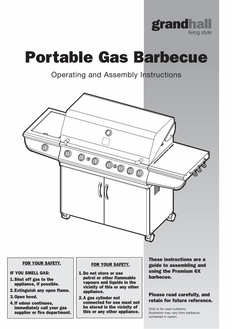
These instructions are aguide to assembling andusing the Premium 6X barbecue.
Please read carefully, and retain for future reference.
Only to be used outdoors. Illustration may vary from barbecue contained in carton.
FOR YOUR SAFETY.
1.Do not store or use petrol or other flammablevapours and liquids in thevicinity of this or any otherappliance.
2.A gas cylinder not connected for use must notbe stored in the vicinity ofthis or any other appliance.
FOR YOUR SAFETY.
IF YOU SMELL GAS:1.Shut off gas to the
appliance, if possible.2.Extinguish any open flame.3.Open hood.4. If odour continues,
immediately call your gassupplier or fire department.
Operating and Assembly Instructions
Portable Gas Barbecue
G E N E R A L I N F O R M A T I O N2 2
The following minimum clearances from combustible materials must bemaintained when barbecue is in use: top – 1000 mm, rear – 450 mm, sides – 250 mm.
Openings at the rear and sides of the appliance provide air forcombustion and must not be obstructed.
CLEARANCES
Height – hood closed 1235 mm, hood open 1605 mm
Width (including trolley) – 1840 mm
Depth – hood closed 660 mm, hood open 715 mm.
OVERALL DIMENSIONS
Appliance specifications can be found on the data label attached to theside panel of the barbecue body.
SPECIFICATIONS
• FAILURE TO COMPLY WITH THESEINSTRUCTIONS COULD RESULT IN AFIRE OR EXPLOSION WHICH COULDCAUSE SERIOUS BODILY INJURY,DEATH OR PROPERTY DAMAGE
• ACCESSIBLE PARTS MAY BE VERY HOT
• KEEP YOUNG CHILDREN AWAY • ANY MODIFICATION OF THIS
APPLIANCE MAY BE DANGEROUS• DO NOT MOVE THIS APPLIANCE
DURING USE • TURN OFF THE GAS SUPPLY AT THE
GAS CYLINDER AFTER USE • READ THE INSTRUCTIONS BEFORE
USING THE APPLIANCE• PARTS SEALED BY THE
MANUFACTURER MUST NOT BE ALTERED IN ANY WAY
• THIS BARBECUE IS ONLY TO BE USED OUTDOORS.
Purchased from
Date purchased
Serial No.
NOTE: Sales docket must be kept as proof of purchase date.
Jackeroo barbecues for use with bottled gas are labelled ‘Universal LPG’or ‘Propane’. Barbecues for use with natural gas are labelled ‘NaturalGas’ and must be installed by an authorised person. Check the gas typesticker attached to the barbecue. Check that the label matches the gastype to be used.
Your barbecue is preset at the factory to operate on bottled gasonly, unless specified otherwise.
FOR CUSTOMER REFERENCE (Record and file in a safe place).
General Information 2Safety 3-4Outdoor Areas 5Pre-Assembly 6Assembly 7-11Inspection 12-13Assembly – General 14Operation 15-17Fault Finding 18Maintenance 19-21Parts Diagram / List 22-23
TABLE OF CONTENTS
The regulator and hose assembly supplied with the barbecue are suitablefor use with bottled gas – POL connection.
This regulator is adjusted to have an outlet pressure of 2.75 kPa forconnection to a gas cylinder only. The regulator and hose assembly suppliedwith the appliance must be used. Replacement regulator and hoseassemblies must be those specified by the appliance manufacturer.
When connecting the hose and regulator assembly to the gas cylinder,take care to avoid unnecessary twisting of the flexible hose. Also, takecare to avoid a loose connection with the gas cylinder. After the assemblyhas been secured, turn on the gas and check for leaks by brushing asoap and water solution over all visible and accessible gas line connections.Include checking those connections which were made by your supplier.The presence of bubbles will indicate a gas escape. DO NOT TEST FORGAS ESCAPES WITH AN OPEN FLAME. If you are unable to correctthe leak by tightening the connections, turn off the gas and contact yourplace of purchase immediately.
Always ensure the appliance is kept away from flammable materialsand the gas cylinder clear of any heat source. When changing over froman empty gas cylinder to a full one, make sure this procedure is carriedout in a flame free atmosphere.
Inspect the gas hose assembly when exchanging the gas cylinder,or at least once a year, whichever is more frequent. If the ‘O-Ring’ or PVChose is cracked, cut, abraded or damaged in any way, the appliance mustnot be operated. The complete assembly must be replaced if damagedand when statutory conditions require it. Contact your place of purchaseif uncertain.
HOSE AND REGULATOR SAFETY
NEVER OPERATE THIS BARBECUE WITHOUT A REGULATOR.
This appliance is certified to AS 4557 by the Australian Gas Association.Refer data label on the barbecue for certificate number.
Barbecues must be used in accordance with the installationrequirements of your local gas supply authority, and the appropriateinstallation standard AS5601.
GAS INSTALLATION CODES
5/8"-18 UNF (3/8" SAE FLARE).
HOSE CONNECTIONS
S A F E T Y3 3
FOR YOUR SAFETY:• DO NOT STORE OR USE PETROL OR
OTHER FLAMMABLE VAPOURS AND LIQUIDS IN THE VICINITY OF THIS OR ANYOTHER APPLIANCE
• DO NOT STORE EMPTY OR FULL SPAREGAS CYLINDERS UNDER OR NEAR THISOR ANY OTHER APPLIANCE
• KEEP THE GAS HOSE AWAY FROM HOTSURFACES. PROTECT GAS HOSE FROMDRIPPING GREASE. AVOID UNNECESSARY TWISTING OFHOSE. VISUALLY INSPECT HOSE PRIOR TO EACH USE FOR CUTS, CRACKS,EXCESSIVE WEAR OR OTHER DAMAGE.REPLACE HOSE, IF NECESSARY
• NEVER TEST FOR GAS LEAKS WITH A LITMATCH OR OPEN FLAME
• NEVER LIGHT BARBECUE WITH LID ON ORHOOD CLOSED
• NEVER LEAN OVER COOKING SURFACE WHILE LIGHTING BARBECUE
• USE GOOD QUALITY INSULATED OVENMITTS WHEN OPERATING BARBECUE
• NEVER ALTER OR MODIFY THEREGULATOR OR GAS SUPPLY ASSEMBLY
• THIS BARBECUE MUST NOT BE USEDINDOORS.
DANGER – IF YOU SMELL OR HEAR THE HISS OF ESCAPING GAS FROM THE GAS CYLINDER:• KEEP CLEAR OF THE GAS CYLINDER• TURN ALL CONTROLS ON THE BARBECUE
TO ‘OFF’• EXTINGUISH ANY OPEN FLAME• REMOVE LID OR OPEN HOOD• IF ODOUR CONTINUES, IMMEDIATELY
CALL YOUR GAS SUPPLIER OR FIREDEPARTMENT.
READ CAREFULLY BEFORE ASSEMBLING AND OPERATING YOUR BARBECUE.
NEVER CONNECT AN UNREGULATED GAS CYLINDER TO YOUR BARBECUE.
• NEVER STORE YOUR GAS CYLINDER INDOOR.
• FOR STORAGE AND CYLINDEREXCHANGE, DISCONNECT HOSE AT THECYLINDER ONLY – DO NOT DISCONNECT HOSE FROM THE APPLIANCE.
DO NOT use your barbecue in garages, porches, breezeways, sheds orother enclosed areas. Your barbecue is to be used OUTDOORS ONLY.Refer to page 5. The barbecue is not intended to be installed in or usedon recreational vehicles and/or boats and should not be placed underany surface that will burn. Do not obstruct the flow of combustion andventilation air around the barbecue housing while in use.
LOCATION OF YOUR BARBECUE
The gas cylinder should be filled by a reputable gas dealer, or exchangedat a reputable gas cylinder exchange outlet. Gas cylinders should bevisually inspected and re-qualified periodically.
Always keep gas cylinder in an upright position. Always close thecylinder valve when the barbecue is not in use.
Do not subject the gas cylinder to excessive heat.
If you store your barbecue indoors, ALWAYS disconnect and remove gascylinder FIRST, and store gas cylinder safely outside. Gas cylindersmust be stored outdoors in a well ventilated area out of reach of children,and must not be stored in a building, garage or any other enclosed area.
This is a low pressure barbecue and must only be used with the hose andregulator supplied.
Your barbecue is designed for use with a 9 kg gas cylinder. Ensuregas cylinder conforms to Australian Standards and is less than 10 years old.
DO NOT CONNECT YOUR BARBECUE TO A GASCYLINDER LESS THAN OR EXCEEDING THIS CAPACITY.
GAS CYLINDER USE & SAFETY
SERVICING
ANY OF THE FOLLOWING SIGNS MAY INDICATE THAT THE APPLIANCE IS NOTOPERATING PROPERLY AND MAY NEEDSERVICING:• EXCESSIVE YELLOW FLAME• IRREGULAR SIZE OF FLAME
ACROSS BURNER• ‘POPPING’ OF FLAME• SOOTING• ABNORMAL NOISE(S)• HISSING SOUND.NOTE: Before requesting service, please refer to page 20 ‘Fault finding’.
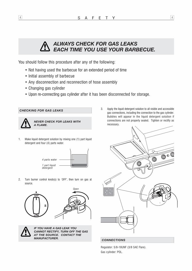
NEVER TEST FOR LEAKS WITH A FLAME.
Prior to first use, and at the beginning of each new season (or, ifusing bottled gas, whenever gas cylinder is changed), you must checkfor gas leaks. Follow these steps:
1. Make soap solution by mixing one part liquid detergent and onepart water.
2. Turn burner control(s) to ‘OFF’, then turn on gas at source.
3. Apply the soap solution to all visible and accessible gas connectionsincluding the gas cylinder. Bubbles will appear in the soap solutionif connections are not properly sealed. Tighten or rectify as necessary.Refer to page 4 for further details.
4. If you have a gas leak you cannot rectify, turn off the gas at thesource. Contact the manufacturer for assistance. Refer to backcover.
CHECKING FOR GAS LEAKS
S A F E T Y4 4
NEVER CHECK FOR LEAKS WITH A FLAME.
IF YOU HAVE A GAS LEAK YOU CANNOT RECTIFY, TURN OFF THE GASAT THE SOURCE. CONTACT THE MANUFACTURER.
ALWAYS CHECK FOR GAS LEAKS EACH TIME YOU USE YOUR BARBECUE.
1. Make liquid detergent solution by mixing one (1) part liquiddetergent and four (4) parts water.
2. Turn burner control knob(s) to ‘OFF’, then turn on gas atsource.
CHECKING FOR GAS LEAKS
You should follow this procedure after any of the following:
• Not having used the barbecue for an extended period of time• Initial assembly of barbecue• Any disconnection and reconnection of hose assembly• Changing gas cylinder• Upon re-connecting gas cylinder after it has been disconnected for storage.
4 parts water
Open
1 part liquiddetergent
3. Apply the liquid detergent solution to all visible and accessiblegas connections, including the connection to the gas cylinder.Bubbles will appear in the liquid detergent solution ifconnections are not properly sealed. Tighten or rectify asnecessary.
Regulator: 5/8-18UNF (3/8 SAE Flare).
Gas cylinder: POL.
CONNECTIONS
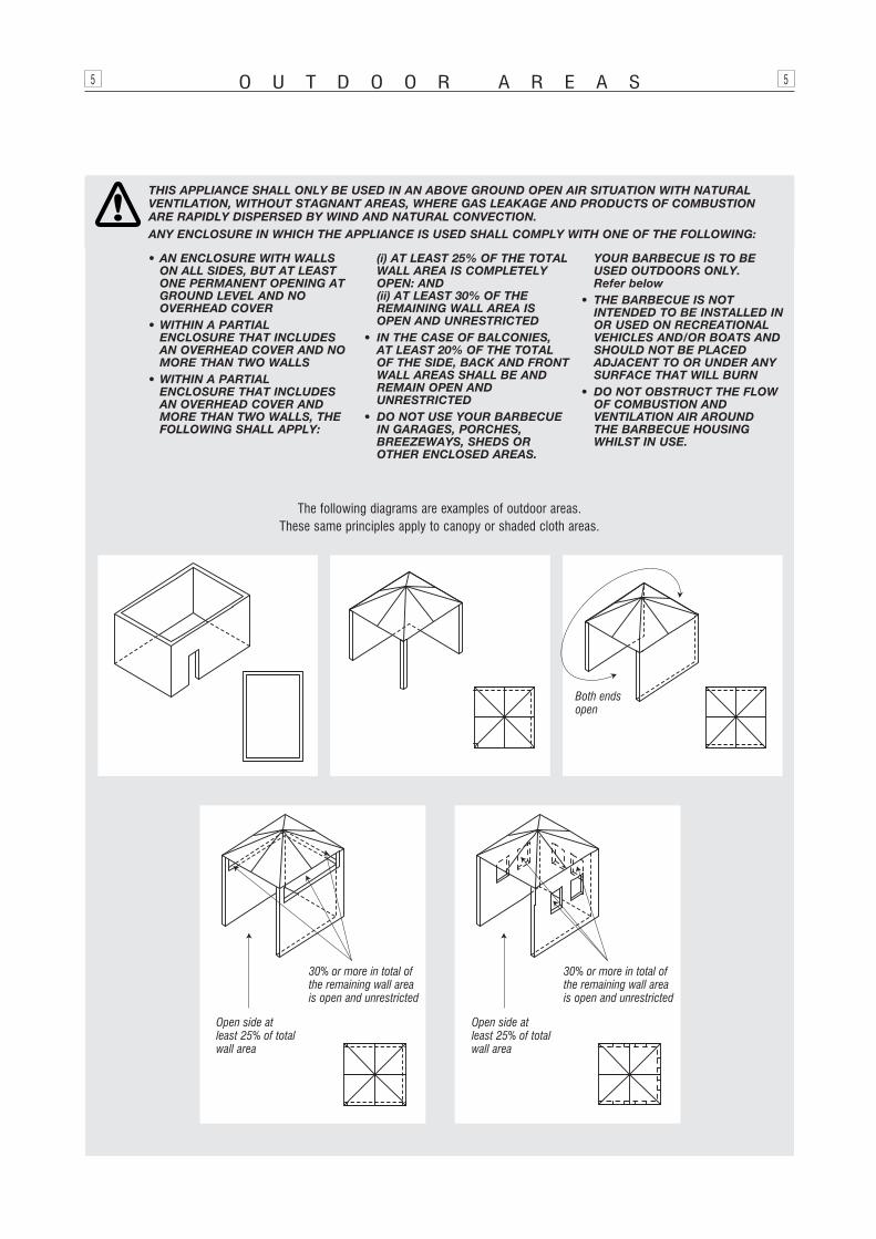
The following diagrams are examples of outdoor areas. These same principles apply to canopy or shaded cloth areas.
THIS APPLIANCE SHALL ONLY BE USED IN AN ABOVE GROUND OPEN AIR SITUATION WITH NATURAL VENTILATION, WITHOUT STAGNANT AREAS, WHERE GAS LEAKAGE AND PRODUCTS OF COMBUSTION ARE RAPIDLY DISPERSED BY WIND AND NATURAL CONVECTION.ANY ENCLOSURE IN WHICH THE APPLIANCE IS USED SHALL COMPLY WITH ONE OF THE FOLLOWING:
O U T D O O R A R E A S5 5
• AN ENCLOSURE WITH WALLSON ALL SIDES, BUT AT LEASTONE PERMANENT OPENING ATGROUND LEVEL AND NO OVERHEAD COVER
• WITHIN A PARTIAL ENCLOSURE THAT INCLUDESAN OVERHEAD COVER AND NOMORE THAN TWO WALLS
• WITHIN A PARTIAL ENCLOSURE THAT INCLUDESAN OVERHEAD COVER ANDMORE THAN TWO WALLS, THEFOLLOWING SHALL APPLY:
(i) AT LEAST 25% OF THE TOTALWALL AREA IS COMPLETELYOPEN: AND(ii) AT LEAST 30% OF THE REMAINING WALL AREA ISOPEN AND UNRESTRICTED
• IN THE CASE OF BALCONIES, AT LEAST 20% OF THE TOTAL OF THE SIDE, BACK AND FRONTWALL AREAS SHALL BE ANDREMAIN OPEN AND UNRESTRICTED
• DO NOT USE YOUR BARBECUEIN GARAGES, PORCHES,BREEZEWAYS, SHEDS OROTHER ENCLOSED AREAS.
YOUR BARBECUE IS TO BE USED OUTDOORS ONLY. Refer below
• THE BARBECUE IS NOT INTENDED TO BE INSTALLED INOR USED ON RECREATIONALVEHICLES AND/OR BOATS ANDSHOULD NOT BE PLACED ADJACENT TO OR UNDER ANYSURFACE THAT WILL BURN
• DO NOT OBSTRUCT THE FLOWOF COMBUSTION AND VENTILATION AIR AROUND THE BARBECUE HOUSINGWHILST IN USE.
Both endsopen
30% or more in total ofthe remaining wall areais open and unrestricted
30% or more in total ofthe remaining wall areais open and unrestricted
Open side atleast 25% of totalwall area
Open side atleast 25% of totalwall area
P R E - A S S E M B L Y6 6
Before attempting to assemble your barbecue, check that all thenecessary parts have been included using the parts list opposite.Inspect barbecue and trolley parts as you proceed.
Contact your place of purchase for assistance regardingreplacement of any damaged or missing parts. Supplier contactdetails are on the back cover of the instruction manual.
Do not assemble or operate a barbecue that appears damaged.
Check that the barbecue supplied is correct for the gas typebeing used. There is a label on the side panel of the barbecueabove the gas connection. Barbecues for use with gas cylindersare labelled ‘Propane’ or ‘Universal LPG’. Barbecues for usewith natural gas are labelled ‘Natural Gas’.
CHECK BARBECUE FOR ANY DAMAGE
While it is possible for one person to assemble the barbecue,we recommend asking for the assistance of another person whenmanoeuvring some of the larger or heavier pieces.
GENERAL
Standard Phillips-head screwdriver.Adjustable spanner (open end shifter).
TOOLS YOU WILL NEED
1. Flatten cardboard packaging and use this as a protectivework surface to assemble upon.
2. Some protective coating may need to be removed fromcomponents prior to assembly.
3. Do not tighten screws and nuts until trolley is fully assembled.4. Pre-screwing of connection points for securing the side
shelves will assist in securing shelves smoothly.
ASSEMBLY TIPS
Description Qty
Side panel – right 1
Side panel – left 1
Bottom shelf 1
Castor seat 4
Castors 4
Trolley bracket – front 1
Gas cylinder housing 1
Door hinge bracket – top left 1
Door hinge bracket – top right 1
Doors 2
Barbecue body assembly 1
Side shelf – right 1
Side burner assembly – left 1
Tool holder 1
Tool hooks 3
Hardware pack 1
Hot plate 2
Grill plate 2
Flame tamer 2
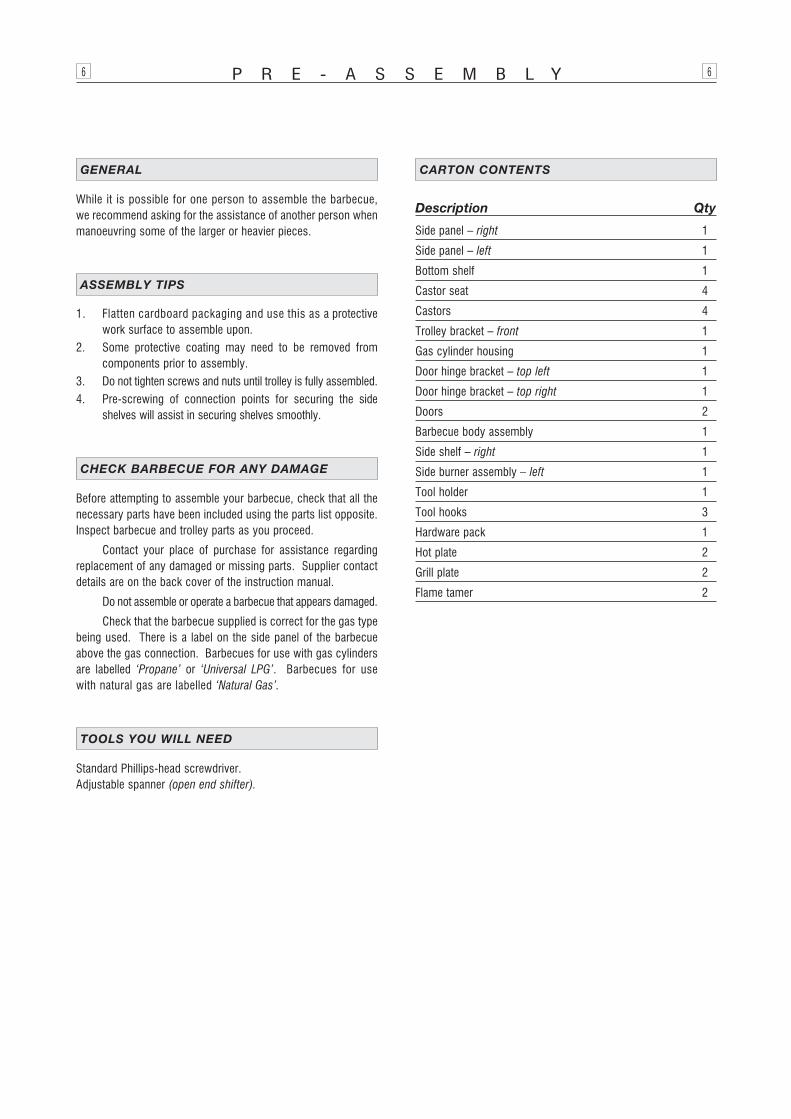
CARTON CONTENTS
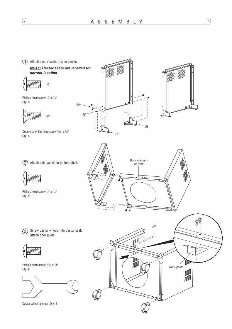
A S S E M B L Y7 7
Phillips-head screw 1/4" x 1/2" Qty: 8
Attach side panels to bottom shelf.2 Door magnets to front
LF / RR
Phillips-head screw 1/4" x 1/2" Qty: 8
Countersunk flat-head screw 3/16" x 3/8" Qty: 8
Attach castor seats to side panels.
NOTE: Castor seats are labelled forcorrect location
1
A
A
BB
LF
LR
Screw castor wheels into castor seat.Attach door guide
3
Phillips-head screw 3/16" x 3/8"Qty: 2
Castor wheel spanner Qty: 1
Door guide
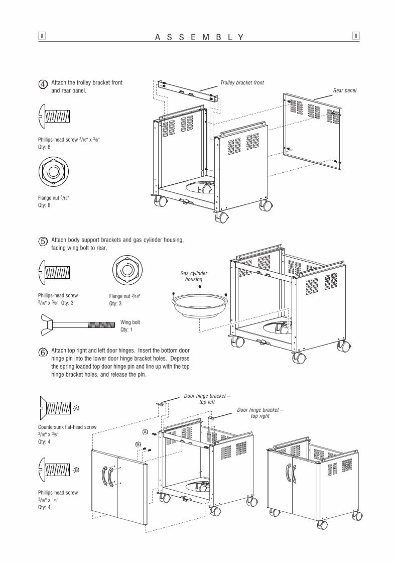
A S S E M B L Y8 8
Phillips-head screw 3/16" x 3/8" Qty: 8
Flange nut 3/16" Qty: 8
Rear panelTrolley bracket front
Phillips-head screw 3/16" x 3/8" Qty: 3
Flange nut 3/16" Qty: 3
Phillips-head screw3/16" x 1/4" Qty: 4
Gas cylinder housing
Door hinge bracket –top left
Door hinge bracket –top right
Countersunk flat-head screw3/16" x 3/8" Qty: 4
B
A
A
B
Attach body support brackets and gas cylinder housing,facing wing bolt to rear.
5
Attach the trolley bracket frontand rear panel.
4
Attach top right and left door hinges. Insert the bottom doorhinge pin into the lower door hinge bracket holes. Depressthe spring loaded top door hinge pin and line up with the tophinge bracket holes, and release the pin.
6
Wing boltQty: 1
G E N E R A L9 9
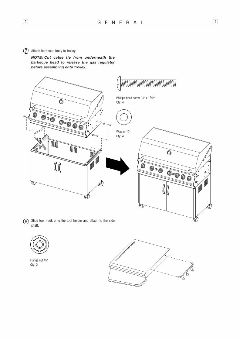
Phillips-head screw 1/4" x 13/16" Qty: 4
Washer 1/4" Qty: 4
Flange nut 1/4" Qty: 2
Slide tool hook onto the tool holder and attach to the sideshelf.
8
Attach barbecue body to trolley.
NOTE: Cut cable tie from underneath thebarbecue head to release the gas regulatorbefore assembling onto trolley.
7
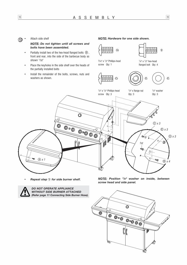
A S S E M B L Y10 10
NOTE: Hardware for one side shown.
1/4" x 1/2" Phillips-head screw Qty: 3
• Attach side shelf
NOTE: Do not tighten until all screws andbolts have been assembled.
• Partially install two of the hex-head flanged bolts ,front and rear, into the side of the barbecue body asshown ‘1st’
• Place the keyholes in the side shelf over the heads ofthe partially installed bolts
• Install the remainder of the bolts, screws, nuts andwashers as shown.
10
1/4" x 1/2" hex-head flanged bolt Qty: 4
1/4" washerQty: 3
1/4" x flange nutQty: 3
3/16" x 1/2" Phillips-head screw Qty: 1
x 1
x 3
1st
x 3
x 3
x 4
A
D EC
B
• Repeat step for side burner shelf. NOTE: Position 1/4" washer on inside, betweenscrew head and side panel.
9
DO NOT OPERATE APPLIANCE WITHOUT SIDE BURNER ATTACHED(Refer page 11 Connecting Side Burner Hose).

A S S E M B L Y11 11
TEST FOR LEAKS WITH A SOAP SOLUTION, NEVER WITH AN OPEN FLAME (Refer pages 3 and 4).
CONNECTING TO, AND DISCONNECTING FROM GAS SOURCE
CONNECTING TO GAS SOURCE
1. Place the gas cylinder into the gas cylinder housing andface the gas cylinder valve to the left front corner. Securewith the wing bolt.
2. Attach cylinder connection device of regulator and hose assembly to cylinder valve outlet. Tighten firmly.
3. Open the gas cylinder valve fully to allow gas to flow.
4. Leak test all accessible connections thoroughly using a soapy water solution prior to lighting the barbecue.Refer to Safety information, pages 3 and 4.
5. If a leak is found, turn gas cylinder valve off and do not usebarbecue until repairs or replacement can be made.
DISCONNECTING FROM GAS SOURCE
1. Turn the burner control ‘OFF’.
2. Turn the gas cylinder valve off fully.
3. Detach the regulator assembly from gas cylinder valve.
This barbecue is also certified for use on natural gas. Contactthe manufacturer for advice in relation to using your barbecue onnatural gas. Refer to back cover.
Barbecues for use on natural gas must be installed by anauthorised person.
NATURAL GAS INSTALLATION
IMPORTANT: Before connecting and disconnectingbarbecue to gas source, ensure burner controls arein ‘OFF’ position.
NOTE: The ‘OFF’ position on the control panel isidentified by either a small black dot / a short verticalblack line / or the word ‘OFF’.
When the marking, or the word ‘OFF’ printed onthe control knob, aligns with the printed marking onthe control panel, then the burner is in the fully offposition.
CAUTION: When the appliance is not in use, the gasmust be turned off at the gas cylinder.
Familiarise yourself with the general information and safetyguidelines located at the front of this booklet. Check to see thatgas cylinder is filled and that end of each burner tube is properlylocated over each valve orifice. Set burner controls to ‘OFF’position.
ENSURING BURNER CONTROLS ARE OFF
• DISCONNECT AND REMOVE GASCYLINDER WHEN MANOEUVRING THEBARBECUE OVER UNEVEN SURFACESOR CARRYING UP AND DOWN STAIRS
• IF THIS INFORMATION IS NOT FOLLOWED EXACTLY, A FIRE CAUSING DEATH OR SERIOUS INJURYMAY OCCUR!
• DO NOT STORE A SPARE GAS CYLINDER UNDER OR NEAR THISAPPLIANCE
• THIS BARBECUE IS ONLY TO BE USED OUTDOORS.
Direction fortightening
CAUTION: Fully handtighten hose nut prior tousing spanner to ensure threads are not ‘cross-threaded’.
Attach the side burner hose to the main barbecue manifold inlet and tighten with a shifter. Take care not to overtighten.
CONNECTING THE SIDE BURNER HOSE
DO NOT USE SEALING TAPE OR COMPOUNDS. USE TOOLS TO SECURECONNECTIONS. TEST FOR LEAKS WITH ASOAP SOLUTION BEFORE LIGHTING – refer to page 3.
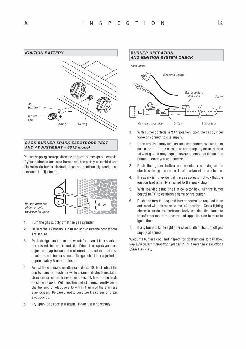
I N S P E C T I O N12 12
Product shipping can reposition the rotisserie burner spark electrode.If your barbecue and side burner are completely assembled andthis rotisserie burner electrode does not continuously spark, thenconduct this adjustment.
1. Turn the gas supply off at the gas cylinder.
2. Be sure the AA battery is installed and ensure the connectionsare secure.
3. Push the ignition button and watch for a small blue spark atthe rotisserie burner electrode tip. If there is no spark you mustadjust the gap between the electrode tip and the stainlesssteel rotisserie burner screen. The gap should be adjusted toapproximately 5 mm or closer.
4. Adjust the gap using needle nose pliers. DO NOT adjust thegap by hand or touch the white ceramic electrode insulator.Using one set of needle nose pliers, securely hold the electrodeas shown above. With another set of pliers, gently bendthe tip end of electrode to within 5 mm of the stainlesssteel screen. Be careful not to puncture the screen or breakelectrode tip.
5. Try spark electrode test again. Re-adjust if necessary.
BACK BURNER SPARK ELECTRODE TEST AND ADJUSTMENT – 5012 model
Do not touch thewhite ceramic electrode insulator
1. With burner controls in ‘OFF’ position, open the gas cylindervalve or connect to gas supply.
2. Upon first assembly the gas lines and burners will be full ofair. In order for the burners to light properly the lines mustfill with gas. It may require several attempts at lighting theburners before you are successful.
3. Push the igniter button and check for sparking at thestainless steel gas collector, located adjacent to each burner.
4. If a spark is not evident at the gas collector, check that theignition lead is firmly attached to the spark plug.
5. With sparking established at collector box, turn the burnercontrol to ‘HI’ to establish a flame on the burner.
6. Push and turn the required burner control as required in ananti-clockwise direction to the ‘HI’ position. Cross lightingchannels inside the barbecue body enables the flame totransfer across to the centre and opposite side burners toignite them.
7. If any burners fail to light after several attempts, turn off gassupply at source.
Wait until burners cool and inspect for obstructions to gas flow.See also Safety instructions (pages 3, 4), Operating instructions(pages 15 - 16).
BURNER OPERATION AND IGNITION SYSTEM CHECK
Electronic igniter
Piezo igniter
5 mm
Gas valve assembly Orifice Burner tube
ScrewGas collector /
electrode
AA battery
Spring
Ignitercap
Contact
IGNITION BATTERY
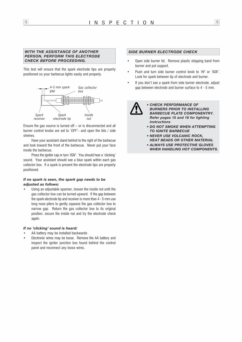
I N S P E C T I O N13 13
This test will ensure that the spark electrode tips are properlypositioned so your barbecue lights easily and properly.
WITH THE ASSISTANCE OF ANOTHER PERSON, PERFORM THIS ELECTRODECHECK BEFORE PROCEEDING.
Ensure the gas source is turned off – or is disconnected and allburner control knobs are set to ‘OFF’– and open the lids / sideshelves.
Have your assistant stand behind to the right of the barbecueand look toward the front of the barbecue. Never put your faceinside the barbecue.
Press the igniter cap or turn ‘IGN’. You should hear a ‘clicking’sound. Your assistant should see a blue spark within each gascollector box. If a spark is present the electrode tips are properlypositioned.
If no spark is seen, the spark gap needs to beadjusted as follows:• Using an adjustable spanner, loosen the inside nut until the
gas collector box can be turned upward. If the gap betweenthe spark electrode tip and receiver is more than 4 - 5 mm uselong nose pliers to gently squeeze the gas collector box tonarrow gap. Return the gas collector box to its originalposition, secure the inside nut and try the electrode checkagain.
If no ‘clicking’ sound is heard:• AA battery may be installed backwards• Electronic wires may be loose. Remove the AA battery and
inspect the igniter junction box found behind the controlpanel and reconnect any loose wires.
• CHECK PERFORMANCE OF BURNERS PRIOR TO INSTALLING BARBECUE PLATE COMPONENTRY.Refer pages 15 and 16 for lighting instructions
• DO NOT SMOKE WHEN ATTEMPTINGTO IGNITE BARBECUE
• NEVER USE VOLCANIC ROCK, HEAT BEADS OR OTHER MATERIAL
• ALWAYS USE PROTECTIVE GLOVESWHEN HANDLING HOT COMPONENTS.
• Open side burner lid. Remove plastic shipping band fromburner and pot support.
• Push and turn side burner control knob to ‘HI’ or ‘IGN’.Look for spark between tip of electrode and burner.
• If you don’t see a spark from side burner electrode, adjustgap between electrode and burner surface to 4 - 5 mm.
SIDE BURNER ELECTRODE CHECK+
-
4-5 mm sparkgap
Gas collectorbox
Spark electrode tip
Sparkreceiver
Inside nut
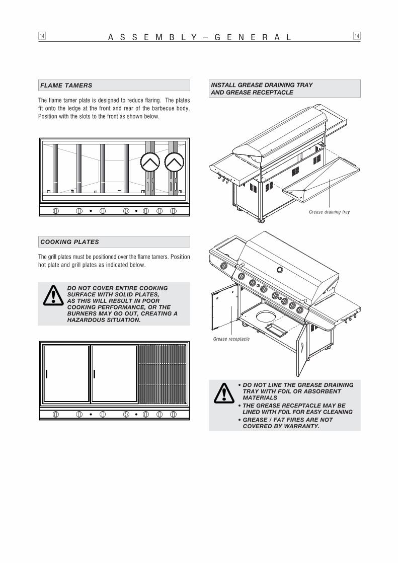
The flame tamer plate is designed to reduce flaring. The platesfit onto the ledge at the front and rear of the barbecue body.Position with the slots to the front as shown below.
FLAME TAMERS
A S S E M B L Y – G E N E R A L14 14
The grill plates must be positioned over the flame tamers. Positionhot plate and grill plates as indicated below.
COOKING PLATES
DO NOT COVER ENTIRE COOKING SURFACE WITH SOLID PLATES, AS THIS WILL RESULT IN POOR COOKING PERFORMANCE, OR THEBURNERS MAY GO OUT, CREATING AHAZARDOUS SITUATION.
• DO NOT LINE THE GREASE DRAININGTRAY WITH FOIL OR ABSORBENT MATERIALS
• THE GREASE RECEPTACLE MAY BELINED WITH FOIL FOR EASY CLEANING
• GREASE / FAT FIRES ARE NOT COVERED BY WARRANTY.
INSTALL GREASE DRAINING TRAY AND GREASE RECEPTACLE
Grease receptacle
Grease draining tray
NOTE: The location of the back burner makes itmore susceptible to wind conditions that willdecrease the performance of your rotisserie cooking.For this reason you should not operate the backburner during windy weather conditions.
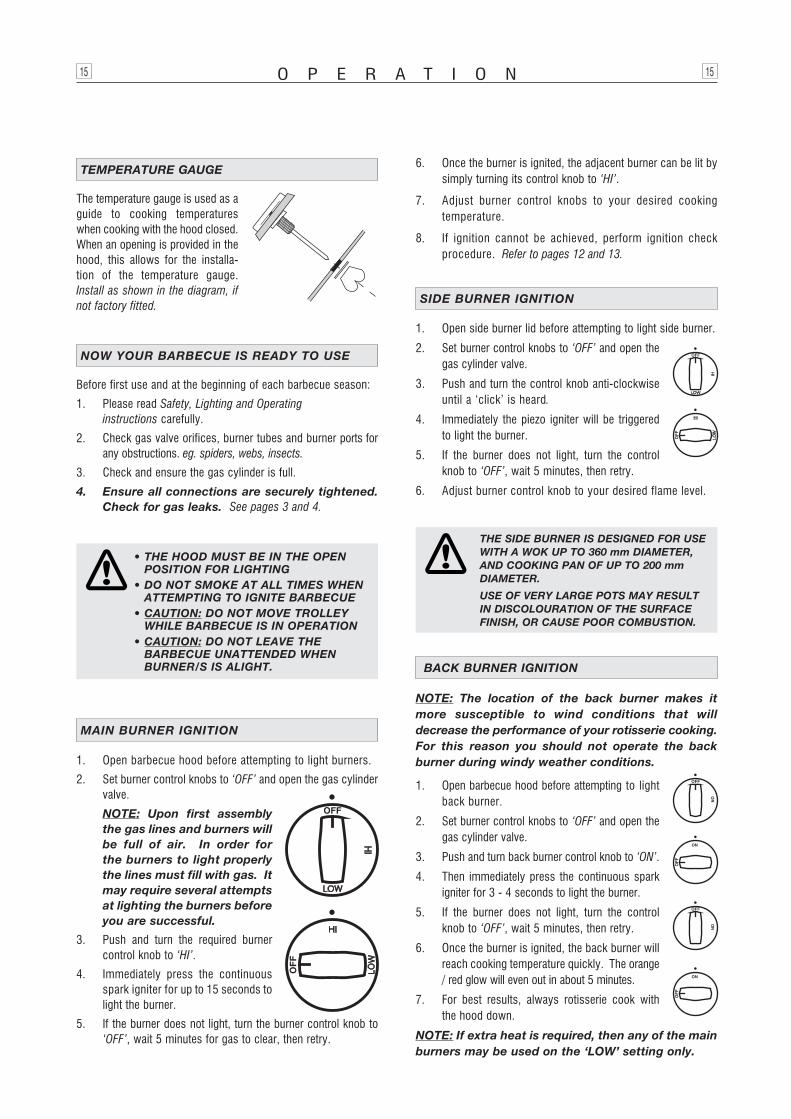
1. Open barbecue hood before attempting to lightback burner.
2. Set burner control knobs to ‘OFF’ and open thegas cylinder valve.
3. Push and turn back burner control knob to ‘ON’.
4. Then immediately press the continuous sparkigniter for 3 - 4 seconds to light the burner.
5. If the burner does not light, turn the controlknob to ‘OFF’, wait 5 minutes, then retry.
6. Once the burner is ignited, the back burner willreach cooking temperature quickly. The orange/ red glow will even out in about 5 minutes.
7. For best results, always rotisserie cook withthe hood down.
NOTE: If extra heat is required, then any of the mainburners may be used on the ‘LOW’ setting only.
BACK BURNER IGNITION
O P E R A T I O N15 15
• THE HOOD MUST BE IN THE OPENPOSITION FOR LIGHTING
• DO NOT SMOKE AT ALL TIMES WHENATTEMPTING TO IGNITE BARBECUE
• CAUTION: DO NOT MOVE TROLLEYWHILE BARBECUE IS IN OPERATION
• CAUTION: DO NOT LEAVE THE BARBECUE UNATTENDED WHEN BURNER/S IS ALIGHT.
1. Open barbecue hood before attempting to light burners.
2. Set burner control knobs to ‘OFF’ and open the gas cylindervalve.
NOTE: Upon first assemblythe gas lines and burners willbe full of air. In order forthe burners to light properlythe lines must fill with gas. Itmay require several attemptsat lighting the burners beforeyou are successful.
3. Push and turn the required burnercontrol knob to ‘HI’.
4. Immediately press the continuousspark igniter for up to 15 seconds tolight the burner.
5. If the burner does not light, turn the burner control knob to‘OFF’, wait 5 minutes for gas to clear, then retry.
MAIN BURNER IGNITION
6. Once the burner is ignited, the adjacent burner can be lit bysimply turning its control knob to ‘HI’.
7. Adjust burner control knobs to your desired cookingtemperature.
8. If ignition cannot be achieved, perform ignition checkprocedure. Refer to pages 12 and 13.
Before first use and at the beginning of each barbecue season:
1. Please read Safety, Lighting and Operating instructions carefully.
2. Check gas valve orifices, burner tubes and burner ports forany obstructions. eg. spiders, webs, insects.
3. Check and ensure the gas cylinder is full.
4. Ensure all connections are securely tightened.Check for gas leaks. See pages 3 and 4.
NOW YOUR BARBECUE IS READY TO USE
The temperature gauge is used as aguide to cooking temperatureswhen cooking with the hood closed.When an opening is provided in thehood, this allows for the installa-tion of the temperature gauge.Install as shown in the diagram, ifnot factory fitted.
TEMPERATURE GAUGE
THE SIDE BURNER IS DESIGNED FOR USEWITH A WOK UP TO 360 mm DIAMETER, AND COOKING PAN OF UP TO 200 mmDIAMETER.
USE OF VERY LARGE POTS MAY RESULTIN DISCOLOURATION OF THE SURFACEFINISH, OR CAUSE POOR COMBUSTION.
1. Open side burner lid before attempting to light side burner.
2. Set burner control knobs to ‘OFF’ and open thegas cylinder valve.
3. Push and turn the control knob anti-clockwiseuntil a ‘click’ is heard.
4. Immediately the piezo igniter will be triggeredto light the burner.
5. If the burner does not light, turn the controlknob to ‘OFF’, wait 5 minutes, then retry.
6. Adjust burner control knob to your desired flame level.
SIDE BURNER IGNITION
O P E R A T I O N16 16
BURN-OFF
Before cooking on your barbecue for the first time, burn-off anyresidual oils or foreign matter from the cooking plates.ENSURE THE LID IS REMOVED OR THE HOODOPEN, and operate at ‘HI’ setting for approximately 15 minutes.Allow to cool then wash grill/plate/pan thoroughly with soap sudsand scrubbing brush. Rinse thoroughly and wipe clean with acloth. Your grill/plate/pan is ready to use.
PREHEATING
It is necessary to preheat the barbecue before cooking.Operate the burner(s) under the cooking surface to be used at‘HI’ for approximately 10 minutes before cooking. Hoodedbarbecues should be pre-heated with the hood down.
OPERATING PROCEDURE
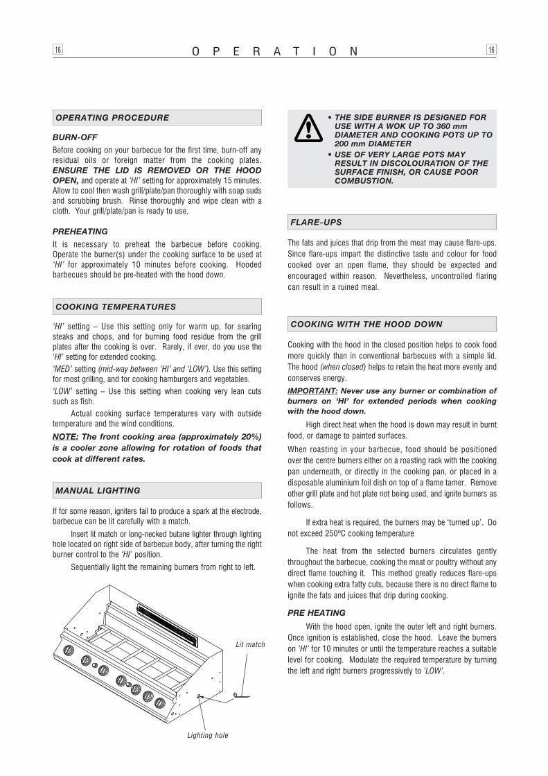
If for some reason, igniters fail to produce a spark at the electrode,barbecue can be lit carefully with a match.
Insert lit match or long-necked butane lighter through lightinghole located on right side of barbecue body, after turning the rightburner control to the ‘HI’ position.
Sequentially light the remaining burners from right to left.
MANUAL LIGHTING
Lighting hole
Lit match
• THE SIDE BURNER IS DESIGNED FOR USE WITH A WOK UP TO 360 mmDIAMETER AND COOKING POTS UP TO200 mm DIAMETER
• USE OF VERY LARGE POTS MAYRESULT IN DISCOLOURATION OF THESURFACE FINISH, OR CAUSE POORCOMBUSTION.
‘HI’ setting – Use this setting only for warm up, for searingsteaks and chops, and for burning food residue from the grillplates after the cooking is over. Rarely, if ever, do you use the‘HI’ setting for extended cooking.‘MED’ setting (mid-way between ‘HI’ and ‘LOW’). Use this settingfor most grilling, and for cooking hamburgers and vegetables.‘LOW’ setting – Use this setting when cooking very lean cutssuch as fish.
Actual cooking surface temperatures vary with outsidetemperature and the wind conditions.
NOTE: The front cooking area (approximately 20%)is a cooler zone allowing for rotation of foods thatcook at different rates.
COOKING TEMPERATURES
The fats and juices that drip from the meat may cause flare-ups.Since flare-ups impart the distinctive taste and colour for foodcooked over an open flame, they should be expected andencouraged within reason. Nevertheless, uncontrolled flaringcan result in a ruined meal.
FLARE-UPS
Cooking with the hood in the closed position helps to cook foodmore quickly than in conventional barbecues with a simple lid.The hood (when closed) helps to retain the heat more evenly andconserves energy.
IMPORTANT: Never use any burner or combination ofburners on ‘HI’ for extended periods when cookingwith the hood down.
High direct heat when the hood is down may result in burntfood, or damage to painted surfaces.
When roasting in your barbecue, food should be positionedover the centre burners either on a roasting rack with the cookingpan underneath, or directly in the cooking pan, or placed in adisposable aluminium foil dish on top of a flame tamer. Removeother grill plate and hot plate not being used, and ignite burners asfollows.
If extra heat is required, the burners may be ‘turned up’. Donot exceed 250ºC cooking temperature
The heat from the selected burners circulates gentlythroughout the barbecue, cooking the meat or poultry without anydirect flame touching it. This method greatly reduces flare-upswhen cooking extra fatty cuts, because there is no direct flame toignite the fats and juices that drip during cooking.
PRE HEATING
With the hood open, ignite the outer left and right burners.Once ignition is established, close the hood. Leave the burnerson ‘HI’ for 10 minutes or until the temperature reaches a suitablelevel for cooking. Modulate the required temperature by turningthe left and right burners progressively to ‘LOW’.
COOKING WITH THE HOOD DOWN
ROTISSERIE COOKING
• Rotisserie cooking produces foods that are moist, flavoursomeand appealing. The rotating food self bastes. Although therotisserie is best for larger pieces of meat or poultry, mostcuts can be used if prepared properly.
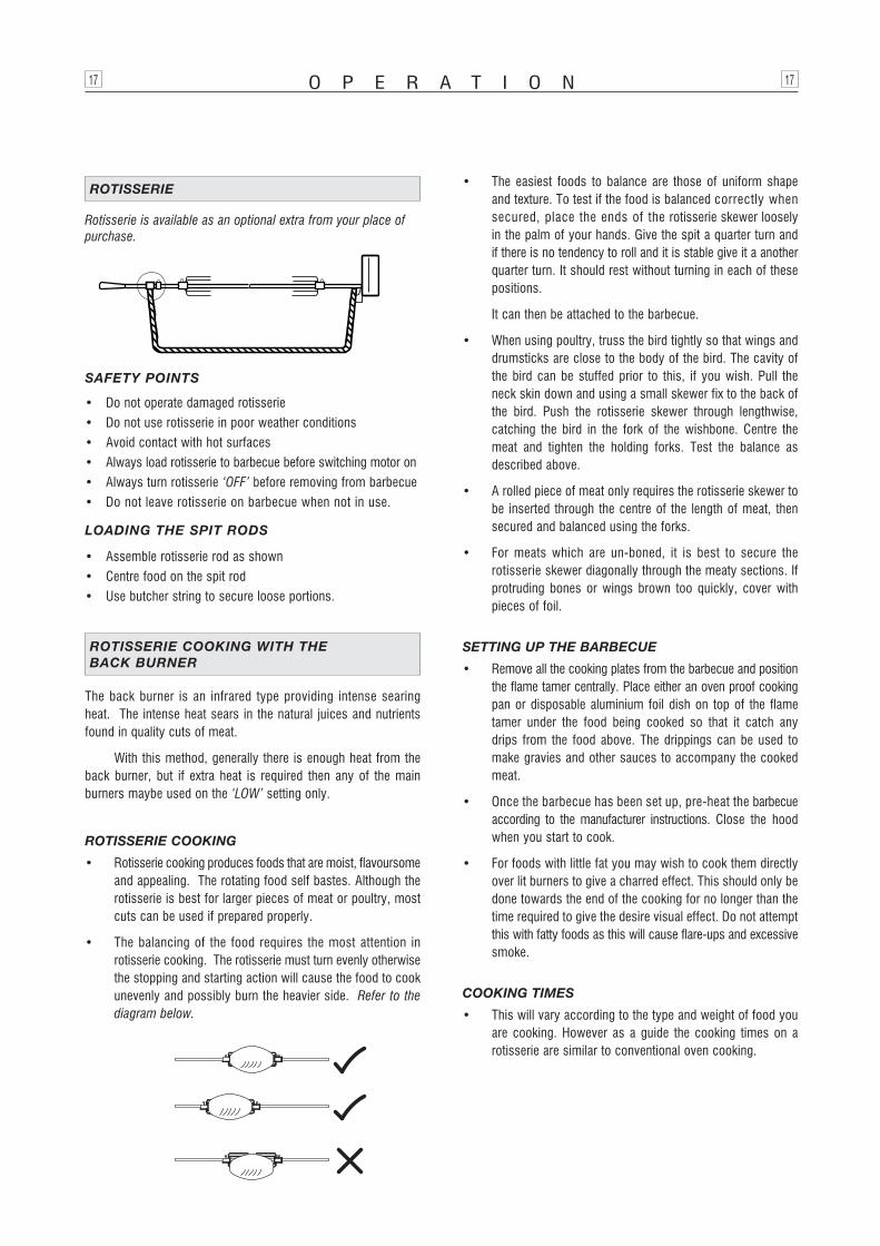
• The balancing of the food requires the most attention inrotisserie cooking. The rotisserie must turn evenly otherwisethe stopping and starting action will cause the food to cookunevenly and possibly burn the heavier side. Refer to thediagram below.
• The easiest foods to balance are those of uniform shapeand texture. To test if the food is balanced correctly whensecured, place the ends of the rotisserie skewer looselyin the palm of your hands. Give the spit a quarter turn andif there is no tendency to roll and it is stable give it a anotherquarter turn. It should rest without turning in each of thesepositions.
It can then be attached to the barbecue.
• When using poultry, truss the bird tightly so that wings anddrumsticks are close to the body of the bird. The cavity ofthe bird can be stuffed prior to this, if you wish. Pull theneck skin down and using a small skewer fix to the back ofthe bird. Push the rotisserie skewer through lengthwise,catching the bird in the fork of the wishbone. Centre themeat and tighten the holding forks. Test the balance asdescribed above.
• A rolled piece of meat only requires the rotisserie skewer tobe inserted through the centre of the length of meat, thensecured and balanced using the forks.
• For meats which are un-boned, it is best to secure therotisserie skewer diagonally through the meaty sections. Ifprotruding bones or wings brown too quickly, cover withpieces of foil.
SETTING UP THE BARBECUE
• Remove all the cooking plates from the barbecue and positionthe flame tamer centrally. Place either an oven proof cookingpan or disposable aluminium foil dish on top of the flametamer under the food being cooked so that it catch anydrips from the food above. The drippings can be used tomake gravies and other sauces to accompany the cookedmeat.
• Once the barbecue has been set up, pre-heat the barbecueaccording to the manufacturer instructions. Close the hoodwhen you start to cook.
• For foods with little fat you may wish to cook them directlyover lit burners to give a charred effect. This should only bedone towards the end of the cooking for no longer than thetime required to give the desire visual effect. Do not attemptthis with fatty foods as this will cause flare-ups and excessivesmoke.
COOKING TIMES
• This will vary according to the type and weight of food youare cooking. However as a guide the cooking times on arotisserie are similar to conventional oven cooking.
O P E R A T I O N17 17
SAFETY POINTS
• Do not operate damaged rotisserie• Do not use rotisserie in poor weather conditions• Avoid contact with hot surfaces• Always load rotisserie to barbecue before switching motor on• Always turn rotisserie ‘OFF’ before removing from barbecue• Do not leave rotisserie on barbecue when not in use.
LOADING THE SPIT RODS
• Assemble rotisserie rod as shown• Centre food on the spit rod• Use butcher string to secure loose portions.
Rotisserie is available as an optional extra from your place ofpurchase.
ROTISSERIE
The back burner is an infrared type providing intense searingheat. The intense heat sears in the natural juices and nutrientsfound in quality cuts of meat.
With this method, generally there is enough heat from theback burner, but if extra heat is required then any of the mainburners maybe used on the ‘LOW’ setting only.
ROTISSERIE COOKING WITH THE BACK BURNER
F A U L T F I N D I N G18 18
SHOULD A FLASHBACK FIRE OCCUR IN OR AROUND THE BURNER TUBES,FOLLOW THE INSTRUCTIONS BELOW.FAILURE TO COMPLY WITH THESEINSTRUCTIONS COULD RESULT IN AFIRE OR EXPLOSION THAT COULDCAUSE SERIOUS BODILY INJURY,DEATH, OR PROPERTY DAMAGE:• SHUT OFF GAS SUPPLY TO THE GAS
BARBECUE• TURN THE CONTROL KNOBS TO OFF
POSITION• OPEN THE BARBECUE LID.
PUT OUT ANY FLAME WITH A FIRE EXTINGUISHER
• ONCE THE BARBECUE HAS COOLEDDOWN, CLEAN THE BURNER TUBESAND BURNERS ACCORDING TO THE CLEANING INSTRUCTIONS IN THISOPERATOR’S MANUAL.
1. Turn gas off at source and turn burner control knobs to‘OFF’. Wait at least five (5) minutes for gas to clear, then retry.
2. If your barbecue still fails to light, check gas supply andconnections.
3. Repeat lighting procedure. If your barbecue still fails tooperate, turn the gas off at source, turn the control knobs to‘OFF’, then check the following:
• Misalignment of burner tubes over orifices
Correction: Reposition burner tubes over orifices.
• Obstruction in gas line
Correction: Remove fuel line from barbecue. Do not smoke!Open gas supply for one second to clear any obstructionfrom fuel line. Close off gas supply at source and reconnectfuel line to barbecue.
• Plugged orifice
Correction: Remove burners from barbecue by pulling cotterpin (beneath burner) using long nose pliers. Carefully lifteach burner up and away from gas valve orifice. Removethe orifice from gas valve and gently clear any obstructionwith a fine wire. Then reinstall all orifices, burners, cotterpins and cooking components.
If an obstruction is suspected in gas valves or manifold,contact your place of purchase or manufacture.
• Obstruction in burner tubes
Correction: Follow the burner tube cleaning procedure onpage 21 of this operator’s manual.
• Misalignment of igniter on burner
Correction: Check for proper position of the electrode tipas shown on pages 12 - 13. The gap between the sparkelectrode tip and spark receiver should be approximately4 - 5 mm. Adjust if necessary. With the gas supplyclosed and all control knobs set to ‘OFF’ press the electronicigniter cap and check for the presence of a spark at theelectrode.
• Disconnected electronic wires
Correction: Inspect the igniter junction box found behind thecontrol panel. Connect loose electronic wires to junctionbox and try to light the barbecue.
• Weak AA battery
Correction: Unscrew the igniter cap and replace the battery.
IF THE BARBECUE FAILS TO LIGHT
CAUTION: If burners go out during operation, closegas supply at source, and turn all gas valves off.Open hood and wait 5 minutes before re-attemptingto light (this allows accumulated gas fumes toclear).
CAUTION: Should grease fire occur, close gas supplyat source, turn off all burners and remove food untilfire is out.
KEEP THE VENTILATION OPENINGS OF THE CYLINDER ENCLOSURE FREE AND CLEAR FROMDEBRIS.
Before initial use, and periodically, wash your cooking plates in amild soap and warm water solution. You can use a wash cloth orvegetable brush to clean your cooking plates.
It is recommended the cooking plates be coated with a thinlayer of cooking oil on a regular basis to prevent rusting. Slightrusting can be removed with a scrubbing brush before use.
CLEANING THE COOKING PLATES
Proper care and maintenance will keep your barbecue in topoperating condition and prolong its life. Follow these cleaningprocedures on a timely basis and your barbecue will stay cleanand operate with minimum effort.
CAUTION: Be sure your barbecue is off and coolbefore cleaning.
CLEANING AND MAINTENANCE
Before initial use, and periodically thereafter, we suggest you washyour barbecue using a mild soap and warm water solution. Youcan use a wash cloth or sponge for this process. Do not use astiff wire or brass brush. These will scratch stainless steel andchip painted surfaces (varies by model) during the cleaningprocess.
CLEANING EXTERIOR SURFACES
To reduce the chance of fire, the grease draining tray and greasereceptacle should be visually inspected before each barbecueuse. Remove any grease and wash grease tray and receptaclewith a mild soap and warm water solution.
NOTE: Grease / fat fires are not covered by warranty.
CLEANING THE GREASE TRAY AND RECEPTACLE
M A I N T E N A N C E19 19
Periodically you should wash the flame tamer in a soap and warmwater solution. Use a vegetable brush to remove stubborn burnt-oncooking residue. Dry the flame tamers thoroughly before youre-install them into the barbecue.
CLEANING THE FLAME TAMERS
The stainless steel over time will be affected by ‘tea staining’ (thebrown discolouration of some stainless steel).
Tea staining can be reduced by washing the surface with milddetergent and warm water. This should then be followed byrinsing with clean cold water. We recommend the surfacethen be wiped dry with a clean cloth.
CARE FOR STAINLESS STEEL SURFACE
FAILURE TO READ AND FOLLOW THE‘USE AND CARE INSTRUCTIONS’ COULDRESULT IN A FIRE OR EXPLOSION THAT COULD CAUSE SERIOUS BODILYINJURY, DEATH OR PROPERTY DAMAGE.
IN COASTAL AREAS, FREQUENTCLEANING AND THE USE OF A COVERIS RECOMMENDED TO PROLONG THELIFE OF THE APPLIANCE. SALTY AIR WILL ADVERSELY AFFECTEXPOSED PARTS.
DO NOT USE OVEN CLEANER TO CLEANTHE BARBECUE.SOME PROPRIETORY BARBECUE CLEANERS MAY AFFECT / DAMAGESOME OF THE SURFACE COATINGSUSED ON THE APPLIANCE.READ THE CLEANER INSTRUCTIONSCAREFULLY.IT IS RECOMMENDED TO TEST IN ANINCONSPICUOUS PLACE FIRST.GENERALLY WE RECOMMEND ONLYWARM SOAPY WATER FOR CLEANINGTHE APPLIANCE.
We recommend that you minimise the barbecue’s exposure tothe elements. High moisture content in the air (rain, mist, saltspray etc.) can affect metal components and lead to materialbreakdown. If left in an area subjected to high moisture content,we strongly recommend that you observe the cleaning procedureon a regular basis and cover the appliance whilst not in use(covers are available as an optional extra). Material breakdownfrom high moisture conditions can be avoided if the appliance iswell protected from the weather and regular cleaning is carried out.
STORAGE
• KEEP BARBECUE AREA CLEAR ANDFREE FROM COMBUSTIBLE MATERIALS,GASOLINE AND OTHER FLAMMABLEVAPOURS AND LIQUIDS
• DO NOT OBSTRUCT THE FLOW OF AIRFOR COMBUSTION AND VENTILATION
• KEEP THE VENTILATION OPENINGS OFTHE CYLINDER ENCLOSURE CABINETFREE AND CLEAR OF DEBRIS
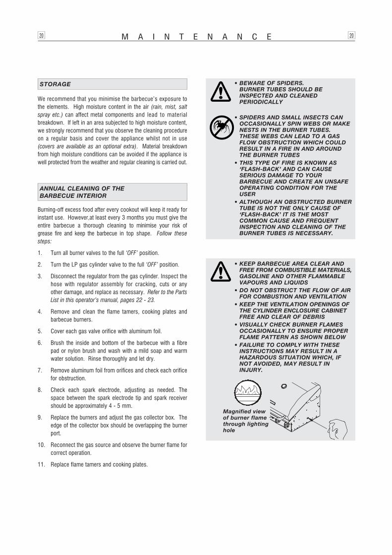
• VISUALLY CHECK BURNER FLAMESOCCASIONALLY TO ENSURE PROPERFLAME PATTERN AS SHOWN BELOW
• FAILURE TO COMPLY WITH THESEINSTRUCTIONS MAY RESULT IN A HAZARDOUS SITUATION WHICH, IF NOT AVOIDED, MAY RESULT ININJURY.
Magnified viewof burner flamethrough lightinghole
Burning-off excess food after every cookout will keep it ready forinstant use. However,at least every 3 months you must give theentire barbecue a thorough cleaning to minimise your risk ofgrease fire and keep the barbecue in top shape. Follow thesesteps:
1. Turn all burner valves to the full ‘OFF’ position.
2. Turn the LP gas cylinder valve to the full ‘OFF’ position.
3. Disconnect the regulator from the gas cylinder. Inspect thehose with regulator assembly for cracking, cuts or anyother damage, and replace as necessary. Refer to the PartsList in this operator’s manual, pages 22 - 23.
4. Remove and clean the flame tamers, cooking plates andbarbecue burners.
5. Cover each gas valve orifice with aluminum foil.
6. Brush the inside and bottom of the barbecue with a fibrepad or nylon brush and wash with a mild soap and warmwater solution. Rinse thoroughly and let dry.
7. Remove aluminum foil from orifices and check each orificefor obstruction.
8. Check each spark electrode, adjusting as needed. Thespace between the spark electrode tip and spark receivershould be approximately 4 - 5 mm.
9. Replace the burners and adjust the gas collector box. Theedge of the collector box should be overlapping the burnerport.
10. Reconnect the gas source and observe the burner flame forcorrect operation.
11. Replace flame tamers and cooking plates.
ANNUAL CLEANING OF THE BARBECUE INTERIOR
M A I N T E N A N C E20 20
• BEWARE OF SPIDERS. BURNER TUBES SHOULD BE INSPECTED AND CLEANED PERIODICALLY
• SPIDERS AND SMALL INSECTS CANOCCASIONALLY SPIN WEBS OR MAKENESTS IN THE BURNER TUBES. THESE WEBS CAN LEAD TO A GASFLOW OBSTRUCTION WHICH COULDRESULT IN A FIRE IN AND AROUNDTHE BURNER TUBES
• THIS TYPE OF FIRE IS KNOWN AS‘FLASH-BACK’ AND CAN CAUSE SERIOUS DAMAGE TO YOUR BARBECUE AND CREATE AN UNSAFEOPERATING CONDITION FOR THEUSER
• ALTHOUGH AN OBSTRUCTED BURNERTUBE IS NOT THE ONLY CAUSE OF‘FLASH-BACK’ IT IS THE MOST COMMON CAUSE AND FREQUENTINSPECTION AND CLEANING OF THEBURNER TUBES IS NECESSARY.
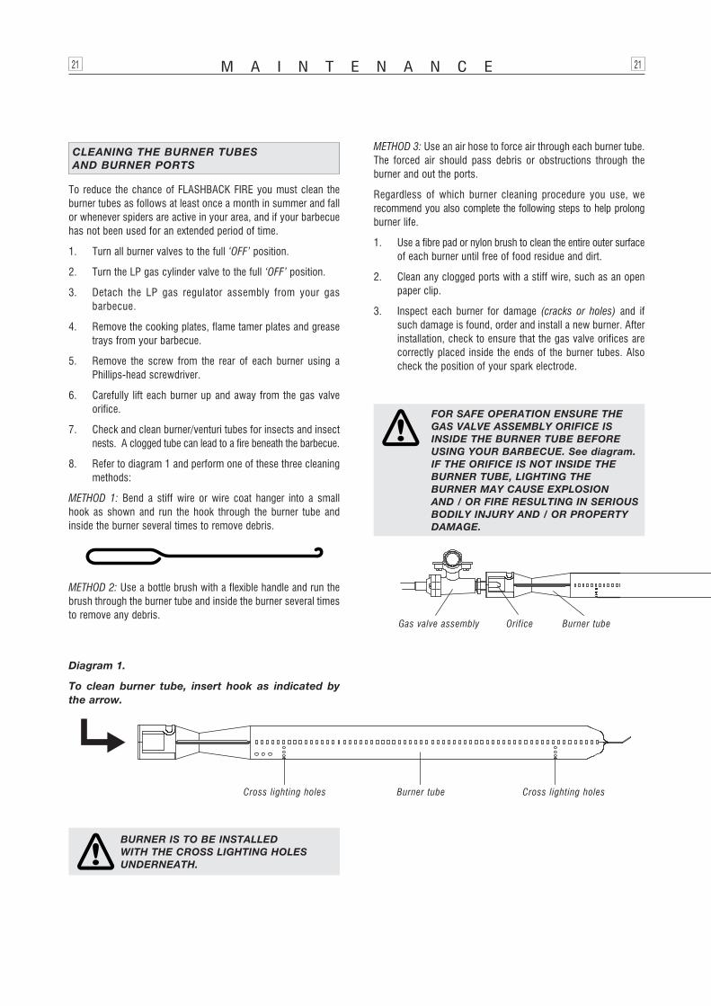
To reduce the chance of FLASHBACK FIRE you must clean theburner tubes as follows at least once a month in summer and fallor whenever spiders are active in your area, and if your barbecuehas not been used for an extended period of time.
1. Turn all burner valves to the full ‘OFF’ position.
2. Turn the LP gas cylinder valve to the full ‘OFF’ position.
3. Detach the LP gas regulator assembly from your gasbarbecue.
4. Remove the cooking plates, flame tamer plates and greasetrays from your barbecue.
5. Remove the screw from the rear of each burner using aPhillips-head screwdriver.
6. Carefully lift each burner up and away from the gas valveorifice.
7. Check and clean burner/venturi tubes for insects and insectnests. A clogged tube can lead to a fire beneath the barbecue.
8. Refer to diagram 1 and perform one of these three cleaningmethods:
METHOD 1: Bend a stiff wire or wire coat hanger into a smallhook as shown and run the hook through the burner tube andinside the burner several times to remove debris.
METHOD 2: Use a bottle brush with a flexible handle and run thebrush through the burner tube and inside the burner several timesto remove any debris.
METHOD 3: Use an air hose to force air through each burner tube.The forced air should pass debris or obstructions through theburner and out the ports.
Regardless of which burner cleaning procedure you use, werecommend you also complete the following steps to help prolongburner life.
1. Use a fibre pad or nylon brush to clean the entire outer surfaceof each burner until free of food residue and dirt.
2. Clean any clogged ports with a stiff wire, such as an openpaper clip.
3. Inspect each burner for damage (cracks or holes) and ifsuch damage is found, order and install a new burner. Afterinstallation, check to ensure that the gas valve orifices arecorrectly placed inside the ends of the burner tubes. Alsocheck the position of your spark electrode.
CLEANING THE BURNER TUBES AND BURNER PORTS
FOR SAFE OPERATION ENSURE THEGAS VALVE ASSEMBLY ORIFICE ISINSIDE THE BURNER TUBE BEFOREUSING YOUR BARBECUE. See diagram.IF THE ORIFICE IS NOT INSIDE THEBURNER TUBE, LIGHTING THEBURNER MAY CAUSE EXPLOSION AND / OR FIRE RESULTING IN SERIOUSBODILY INJURY AND / OR PROPERTYDAMAGE.
M A I N T E N A N C E21 21
Gas valve assembly Orifice Burner tube
BURNER IS TO BE INSTALLED WITH THE CROSS LIGHTING HOLESUNDERNEATH.
Diagram 1.
To clean burner tube, insert hook as indicated bythe arrow.
Burner tubeCross lighting holes Cross lighting holes
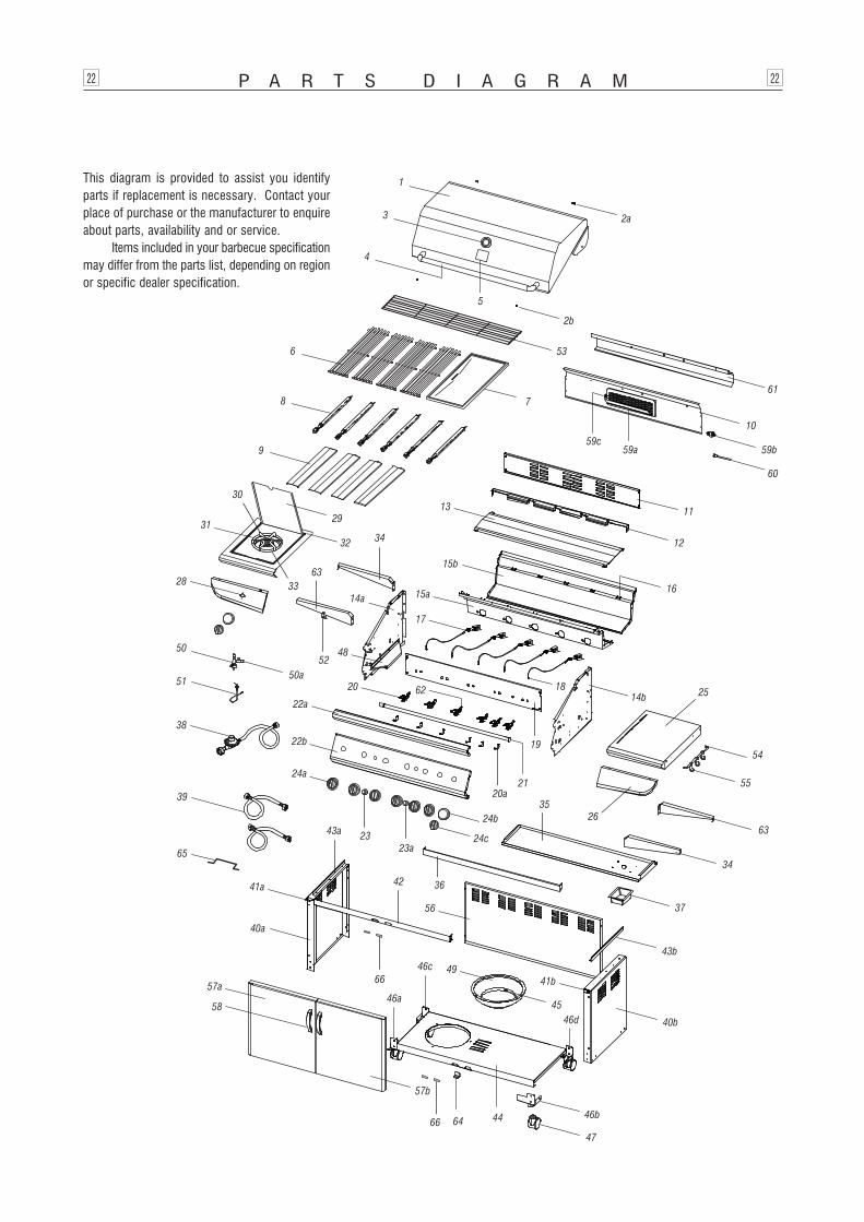
P A R T S D I A G R A M22 22
This diagram is provided to assist you identifyparts if replacement is necessary. Contact yourplace of purchase or the manufacturer to enquireabout parts, availability and or service.
Items included in your barbecue specificationmay differ from the parts list, depending on regionor specific dealer specification.
9
8
30
3129
32
11
12
13
63
52
34
33
50
51
28
23a
38
16
54
26
21
35
20
55
2562
19
17
18
34
63
58
42 36
23
49
37
6466
66
47
45
56
48
50a
39
65
2b
60
10
59a59c
7
6 53
5
1
4
3 2a
61
59b
15b
15a
14b
20a
24b
24c
14a
22a
22b
24a
43a
41a
40a
57a46a
46c
46d
57b
44 46b
41b
43b
40b

P A R T S L I S T23 23
Ref Description Part # Qty1 Hood P00148034B 12a Hood hinge P05501018A 22b Protective pad P05518002I 23 Temperature gauge P00601011B 14 Hood handle P00205068M 15 Name plate P00407006S 16 Grill plate P01615028C 47 Hot plate P01702008H 18 Burner P02008015A 69 Flame tamer P01705011E 410 Body wind shield – back burner P06905028A 111 Rear wind shield P0075101IB 112 Burner bracket P0220606ED 113 Heat shield for body P06903034A 114a Body panel – left P0072052JA 114b Body panel – right P0072152JA 115a Body panel – front P00738449A 115b Body panel – rear P00725449A 116a Flame tamer track – front P033280504 616b Flame tamer track – rear P033280514 617 Gas collector with electrode P02609002B 618 Electronic wire – set P02615081A 119 Gas valve heat shield P03010121B 120 Main burner gas valve – without orifice P03204094A 620a Main burner orifice – LP P06517007A 621 Manifold P05012012G 122a Control panel – top P02910911A 122b Control panel – bottom, with screen print P0291413BA 123a Electronic igniter – 6 point P02502265C 123b Electronic igniter – 2 point P02502252C 124a Burner control knob – main / side P03426201B 724b Knob seat P03415014S 724c Back burner knob P03426361B 125 Side shelf – right P011030084 126 Side shelf decorative panel – bottom right P07502004M 128 Control panel – side burner P07503004M 129 Side shelf lid P0011538P4 130 Side shelf body P011020364 131 Side shelf pot support P00805010B 132 Side shelf trim plate – left P011280044 133 Side burner P02002012A 134 Side shelf bracket – right front / left rear P01206005B 235 Grease draining tray P02717115B 136 Trolley trim bracket – front P033050194 137 Grease receptacle P02701187B 138 Regulator P03603030A 139 Connection tube – side burner P03711035F 240a Trolley panel – left P07605005B 140b Trolley panel – right P07606005B 141a Door hinge bracket – top / left P03313006D 141b Door hinge bracket – top / right P03313007D 142 Trolley bracket – front P03301037D 143a Body support bracket – left P03315001D 143b Body support bracket – right P03315002D 144 Trolley bottom shelf P01004053D 145 Wing bolt S233G05261 146a Castor seat – LF P05327019G 146b Castor seat – RF P05327020G 146c Castor seat – LR P05327018G 146d Castor seat – RR P05327017G 147 3" Castor P05112002A 448 Grease tray track P05330012G 249 Gas cylinder housing P04021003C 150 Side burner valve P03237001G 150a Side burner orifice – LP P06514010A 151 Ignition wire – side burner P02607002A 152 Orifice support bracket P033170344 153 Cooking rack / secondary P01508007H 154 Tool holder P05212013F 155 Tool hook P05514130L 356 Trolley panel – rear P07702044B 157a Door – left P04305004H 157b Door – right P04306004H 158 Door handle P00201001C 259a Back burner – with wind shield P02007014A 159b Back burner orifice – LP P06531014A 159c Back burner electrode P02614025A 160 Back burner connection tube P03717036B 161 Back burner wind shield panel P06905029B 162 Back burner valve P03204015A 163 Side shelf bracket – left front / right rear P01204005B 264 Door guide P05510024P 165 Side burner bracket P033270244 166 Door magnet P05523001K 4
Manifold / gas valve / heat shield assembly Y0060480 1Hardware pack P06003121A 1
P80140244A Printed 6/2008
Focus Lifestyle Products Pty Ltd may collect personal informationabout a consumer of its products in the course of receiving orresponding to a warranty claim. Such information is only collectedto enable the resolution of the warranty claim to the consumer’ssatisfaction, and is not disclosed to other organisations exceptservice agents or sometimes the applicable retailer.
Focus Lifestyle Products has a Privacy Policy (available onrequest), which encompasses compliance with the Privacy Act1988 (Cth). Importantly, individual consumers generally have aright to access information held about them.
PRIVACY POLICY
Manufactured byGrand Hall Enterprise Co Ltd
forFocus Lifestyle Products Pty Ltd
ABN 93 160 136 977
223 - 225 Governor Road, Braeside, Victoria, Australia 3195
P.O. Box 532 Mordialloc, Victoria, Australia 3195
[email protected]: 1800 680 405
Fax: (03) 9587 7965
All specifications are subject to change without notice.