
Portable Appliance Testing
80
PAT: Portable Appliance Testing
description
Portable Appliance Testing
Transcript of Portable Appliance Testing

PAT: Portable Appliance Testing
Prelims-H8736.indd iPrelims-H8736.indd i 4/22/2008 11:42:19 AM4/22/2008 11:42:19 AM
By the same author
Electrical Installation Work, ISBN 978-0-7506-8733-1
Electric Wiring: Domestic, ISBN 978-0-7506-8735-5
Wiring Systems and Fault Finding, ISBN 978-0-7506-8734-8
17th Edition IEE Wiring Regulations: Explained and Illustrated, ISBN 978-0-7506-8720-1
17th Edition IEE Wiring Regulations: Design and Verification of Electrical Installations, ISBN 978-0-7506-8721-8
17th Edition IEE Wiring Regulations: Inspection, Testing and Certification, ISBN 978-0-7506-8719-5
Prelims-H8736.indd iiPrelims-H8736.indd ii 4/22/2008 11:42:19 AM4/22/2008 11:42:19 AM
PAT: Portable Appliance Testing
In-Service Inspection and Testing of Electrical Equipment
Second edition
Brian Scaddan, IEng, MIET
AMSTERDAM • BOSTON • HEIDELBERG • LONDON •NEW YORK • OXFORD • PARIS • SAN DIEGO •
SAN FRANCISCO • SINGAPORE • SYDNEY • TOKYONewnes is an imprint of Elsevier
Prelims1-H8736.indd iiiPrelims1-H8736.indd iii 4/24/2008 5:05:32 PM4/24/2008 5:05:32 PM
Newnes is an imprint of Elsevier Linacre House, Jordan Hill, Oxford OX2 8DP, UK 30 Corporate Drive, Suite 400, Burlington, MA 01803, USA
First published 2000 Revised edition 2003 Second edition 2008
Copyright © 2008, Brian Scaddan. Published by Elsevier Ltd. All rights reserved
The right of Brian Scaddan to be identified as the author of this work has been asserted in accordance with the Copyright, Designs and Patents Act 1988
No part of this publication may be reproduced, stored in a retrieval system or transmitted in any form or by any means electronic, mechanical, photocopying, recording or otherwise without the prior written permission of the publisher
Permissions may be sought directly from Elsevier ’ s Science & Technology Rights Department in Oxford, UK: phone (+44) (0) 1865 843830; fax (+44) (0) 1865 853333; email: [email protected]. Alternatively you can submit your request online by visiting the Elsevier web site at http://elsevier.com/locate/permissions , and selecting Obtaining permission to use Elsevier material
Notice No responsibility is assumed by the publisher for any injury and/or damage to persons or property as a matter of products liability, negligence or otherwise, or from any use or operation of any methods, products, instructions or ideas contained in the material herein
British Library Cataloguing in Publication Data Scaddan, Brian PAT : portable appliance testing : in-service inspection
and testing of electrical equipment. – Rev. ed.1. Electric apparatus and appliances – Testing 2. Electricapparatus and appliances – Testing – Problems, exercises, etc. I. Title 621.3’1042’0287
Library of Congress Control Number: 2008926543
ISBN: 978-0-7506-8736-2
08 09 10 11 11 10 9 8 7 6 5 4 3 2 1
Typeset by Charon Tec Ltd., A Macmillan Company. (www.macmillansolutions.com)
Printed and bound in Slovenia
For information on all Newnes publications visit our website at www.elsevierdirect.com
Prelims1-H8736.indd ivPrelims1-H8736.indd iv 4/24/2008 5:05:33 PM4/24/2008 5:05:33 PM

To Nicola
Prelims1-H8736.indd vPrelims1-H8736.indd v 4/24/2008 5:05:33 PM4/24/2008 5:05:33 PM

Prelims1-H8736.indd viPrelims1-H8736.indd vi 4/24/2008 5:05:33 PM4/24/2008 5:05:33 PM
Contents
PREFACE ............................................................................................. ix
CHAPTER 1 Legislation ........................................................................1 The Health and Safety at Work etc. Act 1974 ..........................................1 The Management of Health and Safety at Work Regulations 1999 ......................................................................1 The Provision and Use of Work Equipment Regulations 1998 .................1 The Electricity at Work Regulations 1989 ............................................... 2 Prosecutions ..........................................................................................3
CHAPTER 2 Setting Up .........................................................................5 Equipment Register .............................................................................. 7 Combined Inspection and Testing Form ................................................ 7 Faulty Equipment and Repair Register ................................................ 10
CHAPTER 3 Equipment to be Inspected and Tested ............................11 Basic Protection ................................................................................. 11 Fault Protection ................................................................................... 11 Class 0 Equipment or Appliances .........................................................12 Class 01 Equipment or Appliances .......................................................12 Class I Equipment or Appliances .......................................................... 12 Class II Equipment or Appliances .........................................................13 Class III Equipment or Appliances ........................................................ 15 Equipment Types .................................................................................16
CHAPTER 4 Inspection .......................................................................19 User Checks ........................................................................................19 Formal Visual Inspection ...................................................................... 20
vii
Prelims1-H8736.indd viiPrelims1-H8736.indd vii 4/24/2008 5:05:33 PM4/24/2008 5:05:33 PM
viii
CHAPTER 5 Combined Inspection and Testing .................................. 23 Testing ................................................................................................23 Preliminary Inspection ......................................................................... 23
APPENDIX 1 Shock Risk ....................................................................35 Electric Shock .................................................................................... 35 Basic Protection .................................................................................. 37 Fault Protection ................................................................................... 37 What Is Earth and Why and How We Connect to It? ..............................38
APPENDIX 2 Basic Electrical Theory Revision ....................................43 Electrical Quantities and Units ............................................................. 43 Relationship Between Voltage, Current and Resistance ........................44 Common Multiples of Units ..................................................................44 Resistance in Series ........................................................................... 44 Resistance in Parallel ..........................................................................45
APPENDIX 3 Sample 2377 Questions .................................................49 The Management of Electrical Equipment Maintenance .......................49 Inspection and Testing of Electrical Equipment ..................................... 59
APPENDIX 4 Answers to Sample 2377 Questions .............................. 67 The Management of Electrical Equipment Maintenance ...................... 67 Inspection and Testing of Electrical Equipment ................................... 67
INDEX ................................................................................................ 69
Contents
Prelims1-H8736.indd viiiPrelims1-H8736.indd viii 4/24/2008 5:05:33 PM4/24/2008 5:05:33 PM
ix
Preface
The introduction of The Electricity at Work Regulations (EAWR) 1989 prompted, among many other things, a rush to inspect and test portable appliances . The Regulations do not require such inspecting and testing, nor do they specifically mention portable appliances. They do, however, require any electrical system to be constructed, maintained and used in such a manner as to prevent danger, and in consequence inspection and testing of systems (port-able appliances are systems) is needed in order to determine if maintenance is required.
All electrical equipment connected to the fixed wiring of an instal-lation will need attention, not just portable appliances. I have how-ever left the title of this book as PAT: Portable Appliance Testing as such words are now indelibly imprinted on our minds, even though it should read ‘ Inspection and Testing of In-service Electrical Equipment ’ .
The book is intended for those who need be involved in this inspection and testing process, either as a business venture or as an ‘ in-house ’ procedure to conform with the EAWR. It is also a use-ful reference document for anyone embarking on a City & Guilds 2377 course.
Brian Scaddan, April 2008
This new edition has been updated in line with the 17th Edition Wiring Regulations and the 3rd edition of the Code of Practice for In-Service Inspection and Testing of Electrical Equipment.
Preface-H8736.indd ixPreface-H8736.indd ix 4/24/2008 5:05:03 PM4/24/2008 5:05:03 PM

Acknowledgements
I would like to thank Paul Clifford for his thorough technical proof reading.
Preface-H8736.indd xPreface-H8736.indd x 4/24/2008 5:05:03 PM4/24/2008 5:05:03 PM
1
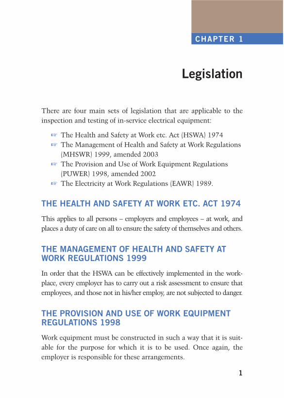
Legislation
There are four main sets of legislation that are applicable to the inspection and testing of in-service electrical equipment:
The Health and Safety at Work etc. Act (HSWA) 1974 The Management of Health and Safety at Work Regulations
(MHSWR) 1999, amended 2003 The Provision and Use of Work Equipment Regulations
(PUWER) 1998, amended 2002 The Electricity at Work Regulations (EAWR) 1989.
THE HEALTH AND SAFETY AT WORK ETC. ACT 1974
This applies to all persons – employers and employees – at work, and places a duty of care on all to ensure the safety of themselves and others.
THE MANAGEMENT OF HEALTH AND SAFETY AT WORK REGULATIONS 1999
In order that the HSWA can be effectively implemented in the work-place, every employer has to carry out a risk assessment to ensure that employees, and those not in his/her employ, are not subjected to danger.
THE PROVISION AND USE OF WORK EQUIPMENT REGULATIONS 1998
Work equipment must be constructed in such a way that it is suit-able for the purpose for which it is to be used. Once again, the employer is responsible for these arrangements.
CHAPTER 1
ch01-h8736.indd 1ch01-h8736.indd 1 4/22/2008 10:23:24 AM4/22/2008 10:23:24 AM
2
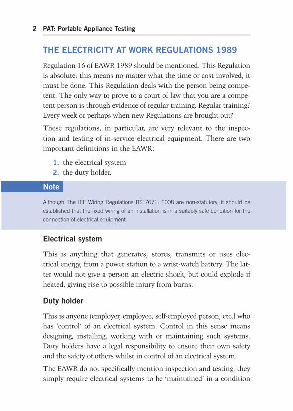
THE ELECTRICITY AT WORK REGULATIONS 1989
Regulation 16 of EAWR 1989 should be mentioned. This Regulation is absolute; this means no matter what the time or cost involved, it must be done. This Regulation deals with the person being compe-tent. The only way to prove to a court of law that you are a compe-tent person is through evidence of regular training. Regular training? Every week or perhaps when new Regulations are brought out?
These regulations, in particular, are very relevant to the inspec-tion and testing of in-service electrical equipment. There are two important definitions in the EAWR:
1. the electrical system 2. the duty holder.
PAT: Portable Appliance Testing
Note
Although The IEE Wiring Regulations BS 7671: 2008 are non-statutory, it should be
established that the fixed wiring of an installation is in a suitably safe condition for the
connection of electrical equipment.
Electrical system
This is anything that generates, stores, transmits or uses elec-trical energy, from a power station to a wrist-watch battery. The lat-ter would not give a person an electric shock, but could explode if heated, giving rise to possible injury from burns.
Duty holder
This is anyone (employer, employee, self-employed person, etc.) who has ‘ control ’ of an electrical system. Control in this sense means designing, installing, working with or maintaining such systems. Duty holders have a legal responsibility to ensure their own safety and the safety of others whilst in control of an electrical system.
The EAWR do not specifically mention inspection and testing; they simply require electrical systems to be ‘ maintained ’ in a condition
ch01-h8736.indd 2ch01-h8736.indd 2 4/22/2008 10:23:24 AM4/22/2008 10:23:24 AM
3
so as not to cause danger. However, we only know if a system needs to be maintained if it is inspected and tested, and thus the need for such inspection and testing of a system is implicit in the require-ment for it to be maintained.
Anyone who inspects and tests an electrical system is, in law, a duty holder and must be competent to undertake such work.
PROSECUTIONS
Offences committed under The EAWR 1989 may be liable for: £20 000 fine for each offence in Magistrates ’ Court, unlimited fines/prison sentences in Crown Court.
Here are just a few examples of the many prosecutions under the EAWR 1989 that take place every year.
Legislation
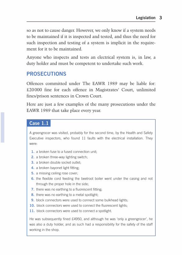
Case 1.1
A greengrocer was visited, probably for the second time, by the Health and Safety
Executive inspectors, who found 11 faults with the electrical installation. They
were:
1. a broken fuse to a fused connection unit;
2. a broken three-way lighting switch;
3. a broken double socket outlet;
4. a broken bayonet light fitting;
5. a missing ceiling rose cover;
6. the flexible cord feeding the beetroot boiler went under the casing and not
through the proper hole in the side;
7. there was no earthing to a fluorescent fitting;
8. there was no earthing to a metal spotlight;
9. block connectors were used to connect some bulkhead lights;
10. block connectors were used to connect the fluorescent lights;
11. block connectors were used to connect a spotlight.
He was subsequently fined £4950, and although he was ‘ only a greengrocer ’ , he
was also a duty holder, and as such had a responsibility for the safety of the staff
working in the shop.
ch01-h8736.indd 3ch01-h8736.indd 3 4/22/2008 10:23:24 AM4/22/2008 10:23:24 AM
PAT: Portable Appliance Testing4
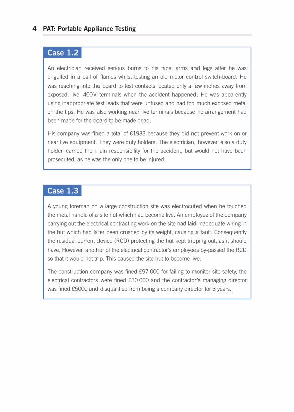
Case 1.2
An electrician received serious burns to his face, arms and legs after he was
engulfed in a ball of flames whilst testing an old motor control switch-board. He
was reaching into the board to test contacts located only a few inches away from
exposed, live, 400 V terminals when the accident happened. He was apparently
using inappropriate test leads that were unfused and had too much exposed metal
on the tips. He was also working near live terminals because no arrangement had
been made for the board to be made dead.
His company was fined a total of £1933 because they did not prevent work on or
near live equipment. They were duty holders. The electrician, however, also a duty
holder, carried the main responsibility for the accident, but would not have been
prosecuted, as he was the only one to be injured.
Case 1.3
A young foreman on a large construction site was electrocuted when he touched
the metal handle of a site hut which had become live. An employee of the company
carrying out the electrical contracting work on the site had laid inadequate wiring in
the hut which had later been crushed by its weight, causing a fault. Consequently
the residual current device (RCD) protecting the hut kept tripping out, as it should
have. However, another of the electrical contractor’s employees by-passed the RCD
so that it would not trip. This caused the site hut to become live.
The construction company was fined £97 000 for failing to monitor site safety, the
electrical contractors were fined £30 000 and the contractor’s managing director
was fined £5000 and disqualified from being a company director for 3 years.
ch01-h8736.indd 4ch01-h8736.indd 4 4/22/2008 10:23:25 AM4/22/2008 10:23:25 AM
5
Setting Up
There are two ways for an organization to ensure that in-service electrical equipment is regularly maintained:
employ a specialist company to provide the inspection and testing service; or
arrange for ‘ in-house ’ staff to carry out the work through relevant training to ensure competence and hence compliance Regulation 16 of the EAWR.
In either case, the first step is for the organization to appoint a ‘ responsible person ’ who will, therefore, be a duty holder and to whom staff and/or outside contractors should report the results of any inspection and test, including defects, etc. Such a person could be the manager of the premises or a member of staff: they will need to be trained and competent, both in the management of the appliance testing process and in the knowledge of relevant legislation as discussed in Chapter 1.
The second step is for the ‘ responsible person ’ to carry out an inventory of all equipment that will need testing and/or inspect-ing, and make decisions as to the frequency of such work. Some advice may be needed here from an experienced contractor in order to achieve the most effective time schedule and to make decisions on which equipment should be involved.
Table 2.1 gives some examples of recommended periods between each inspection and test.
CHAPTER 2
Ch02-H8736.indd 5Ch02-H8736.indd 5 4/24/2008 5:09:32 PM4/24/2008 5:09:32 PM
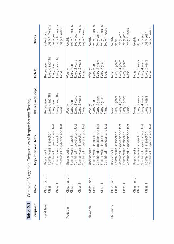
Tabl
e 2
.1
Sam
ple
of S
ugge
sted
Fre
quen
cies
of I
nspe
ctio
n an
d Te
stin
g .
Equ
ipm
ent
Cla
ss
Insp
ecti
on a
nd T
ests
O
ffic
es a
nd S
hops
H
otel
s S
choo
ls
Han
d-he
ld
Cla
ss I
and
II U
ser
chec
ks
Bef
ore
use
Bef
ore
use
Bef
ore
use
C
lass
I Fo
rmal
vis
ual i
nspe
ctio
n Ev
ery
6 m
onth
s Ev
ery
6 m
onth
s Ev
ery
4 m
onth
s
C
ombi
ned
insp
ectio
n an
d te
st
Ever
y ye
ar
Ever
y ye
ar
Ever
y ye
ar
C
lass
II
Form
al v
isua
l ins
pect
ion
Ever
y 6
mon
ths
Ever
y 6
mon
ths
Ever
y 4
mon
ths
Com
bine
d in
spec
tion
and
test
N
one
Non
e Ev
ery
4 ye
ars
Por
tabl
e C
lass
I an
d II
Use
r ch
ecks
W
eekl
y W
eekl
y W
eekl
y
Cla
ss I
Form
al v
isua
l ins
pect
ion
Ever
y ye
ar
Ever
y ye
ar
Ever
y 4
mon
ths
Com
bine
d in
spec
tion
and
test
Ev
ery
2 ye
ars
Ever
y 2
year
s Ev
ery
year
Cla
ss II
Fo
rmal
vis
ual i
nspe
ctio
n Ev
ery
2 ye
ars
Ever
y 2
year
s Ev
ery
4 m
onth
s
C
ombi
ned
insp
ectio
n an
d te
st
Non
e N
one
Ever
y 4
year
s
Mov
eabl
e C
lass
I an
d II
Use
r ch
ecks
W
eekl
y W
eekl
y W
eekl
y
Cla
ss I
Form
al v
isua
l ins
pect
ion
Ever
y ye
ar
Ever
y ye
ar
Ever
y 4
mon
ths
Com
bine
d in
spec
tion
and
test
Ev
ery
2 ye
ars
Ever
y 2
year
s Ev
ery
year
Cla
ss II
Fo
rmal
vis
ual i
nspe
ctio
n Ev
ery
2 ye
ars
Ever
y 2
year
s Ev
ery
4 m
onth
s
C
ombi
ned
insp
ectio
n an
d te
st
Non
e N
one
Ever
y 4
year
s
Stat
iona
ry
Cla
ss I
and
II U
ser
chec
ks
Non
e N
one
Wee
kly
C
lass
I Fo
rmal
vis
ual i
nspe
ctio
n Ev
ery
2 ye
ars
Ever
y 2
year
s N
one
Com
bine
d in
spec
tion
and
test
Ev
ery
4 ye
ars
Ever
y 4
year
s Ev
ery
year
Cla
ss II
Fo
rmal
vis
ual i
nspe
ctio
n Ev
ery
2 ye
ars
Ever
y 2
year
s Ev
ery
year
C
ombi
ned
insp
ectio
n an
d te
st
Non
e N
one
Ever
y 4
year
s
IT
Cla
ss I
and
II U
ser
chec
ks
Non
e N
one
Wee
kly
C
lass
I Fo
rmal
vis
ual i
nspe
ctio
n Ev
ery
2 ye
ars
Ever
y 2
year
s N
one
Com
bine
d in
spec
tion
and
test
Ev
ery
4 ye
ars
Ever
y 4
year
s Ev
ery
year
Cla
ss II
Fo
rmal
vis
ual i
nspe
ctio
n Ev
ery
2 ye
ars
Ever
y 2
year
s Ev
ery
year
C
ombi
ned
insp
ectio
n an
d te
st
Non
e N
one
Ever
y 4
year
s
Ch02-H8736.indd 6Ch02-H8736.indd 6 4/24/2008 5:09:32 PM4/24/2008 5:09:32 PM
Setting Up 7
The ‘ responsible person ’ should have in place a procedure for users of electrical equipment to report and log any defects found.
Whether the inspection and test is to be carried out by competent staff or by outside contractors, it is advisable that various forms be produced.
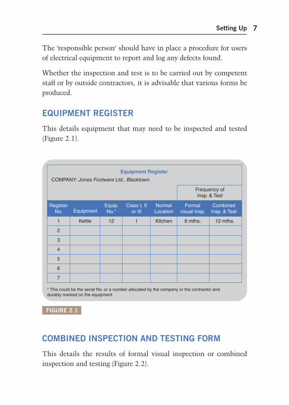
EQUIPMENT REGISTER
This details equipment that may need to be inspected and tested ( Figure 2.1 ) .
FIGURE 2.1
Equipment Register
Frequency ofInsp. & Test
RegisterNo. Equipment
Equip.No.*
Class I, IIor III
NormalLocation
Formalvisual Insp.
CombinedInsp. & Test
COMPANY: Jones Footware Ltd., Blacktown.
1 Kettle 12 I Kitchen 6 mths. 12 mths.
2
3
4
5
6
7
* This could be the serial No. or a number allocated by the company or the contractor anddurably marked on the equipment
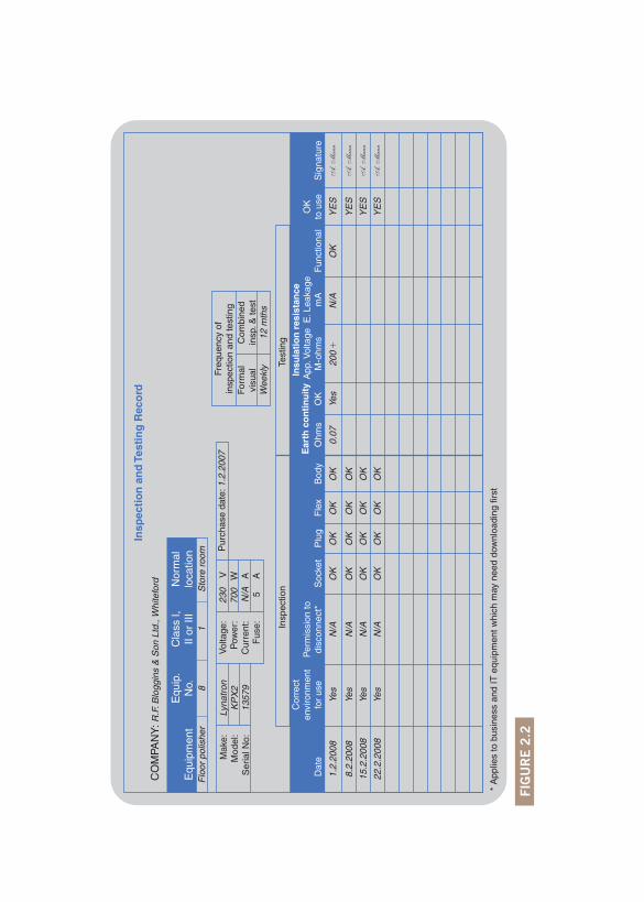
COMBINED INSPECTION AND TESTING FORM
This details the results of formal visual inspection or combined inspection and testing ( Figure 2.2 ) .
Ch02-H8736.indd 7Ch02-H8736.indd 7 4/24/2008 5:09:32 PM4/24/2008 5:09:32 PM
FI
GU
RE
2.2
Insp
ecti
on
an
d T
esti
ng
Rec
ord
Equ
ipm
ent
Insp
ectio
n
Dat
e
1.2.
2008
Yes
YE
S
YE
S
YE
S
YE
S
N/A
OK
OK
OK
OK
OK
OK
OK
OK
OK
OK
OK
OK
OK
OK
0.07
Yes
200
OK
OK
OK
N/A
N/A
N/A
N/A
Yes
Yes
Yes
8.2.
2008
15.2
.200
8
22.2
.200
8
Cor
rect
envi
ronm
ent
for
use
Per
mis
sion
todi
scon
nect
*
* A
pplie
s to
bus
ines
s an
d IT
equ
ipm
ent w
hich
may
nee
d do
wnl
oadi
ng fi
rst
Soc
ket
Plu
gF
lex
Bod
yE
arth
co
nti
nu
ity
Test
ing
Insu
lati
on
res
ista
nce
App
. Vol
tage
M-o
hms
Fun
ctio
nal
OK
to u
seS
igna
ture
Freq
uenc
y of
insp
ectio
n an
d te
stin
gF
orm
alvi
sual
Com
bine
din
sp. &
test
Wee
kly
12 m
ths
Ohm
sO
K
Mak
e:M
odel
:S
eria
l No:
Vol
tage
:P
ower
:C
urre
nt:
Fus
e:
Pur
chas
e da
te: 1
.2.2
007
Flo
or p
olis
her
81
Sto
re r
oom
Equ
ip.
No.
Cla
ss I,
II or
III
Nor
mal
loca
tion
CO
MPA
NY
: R.F
. Blo
ggin
s &
Son
Ltd
., W
hite
ford
Lyna
tron
KP
X2
1357
9
230
V
700
WN
/A
A 5
A
E. L
eaka
gem
A
Ch02-H8736.indd 8Ch02-H8736.indd 8 4/24/2008 5:09:32 PM4/24/2008 5:09:32 PM
FI
GU
RE
2.3
Fau
lty
Eq
uip
men
t &
Rep
air
Reg
iste
r
Dat
e re
mov
edfr
om s
ervi
ce
13.3
.200
8H
air
drye
r9 11
4M
ain
salo
nFr
ayed
flex
20.3
.200
828
.3.2
008
Yes
No
1.4.
2008
N.O
. Goo
d
T.O
. Bad
20.3
.200
8C
rack
ed h
andl
eR
oom
218
Cur
ling
tong
s15
.3.2
008
Equ
ipm
ent
Equ
ip.
No.
Equ
ipm
ent
regi
ster
No.
Nor
mal
loca
tion
Faul
tD
ate
sent
for
repa
irR
epai
rer
Dat
ere
turn
ed
Su
itab
le fo
r u
se
OK
Sig
natu
reC
omm
ents
Not
rep
aira
ble
CO
MPA
NY
: Mr.
Bal
dys
Hai
rdre
ssin
g E
mpo
rium
, Thi
ntow
n
Ch02-H8736.indd 9Ch02-H8736.indd 9 4/24/2008 5:09:33 PM4/24/2008 5:09:33 PM
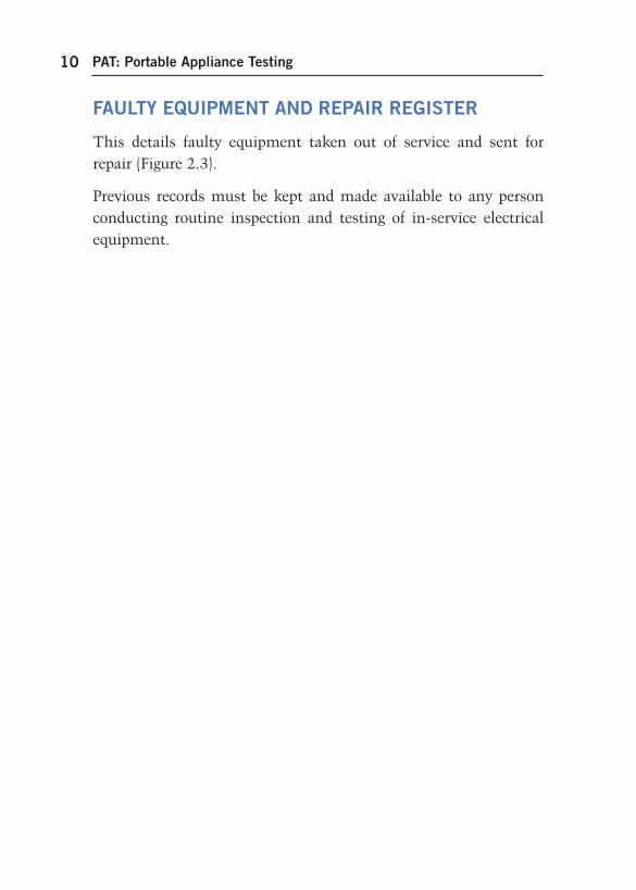
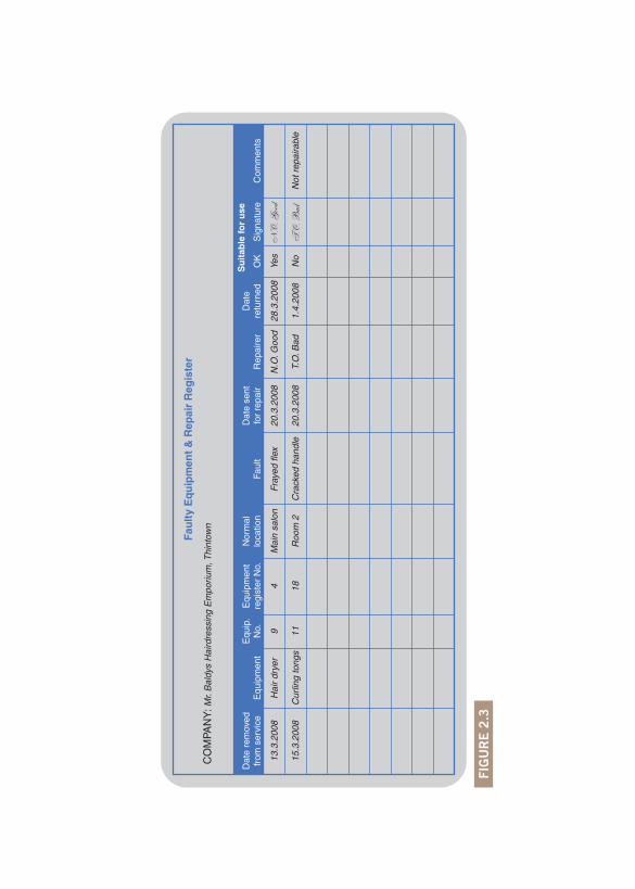
FAULTY EQUIPMENT AND REPAIR REGISTER
This details faulty equipment taken out of service and sent for repair ( Figure 2.3 ).
Previous records must be kept and made available to any person conducting routine inspection and testing of in-service electrical equipment.
PAT: Portable Appliance Testing10
Ch02-H8736.indd 10Ch02-H8736.indd 10 4/24/2008 5:09:33 PM4/24/2008 5:09:33 PM
11
Equipment to be Inspected and Tested
As mentioned in the Preface to this book, it is not just portable appliances that have to be inspected and tested, but all in-service electrical equipment. This includes items connected to the supply by 13 A BS 1363 plugs, BS EN 60309-2 industrial plugs or hard wired to the fixed installation via fused connection units or single- or three-phase isolators.
It is perhaps wise at this stage to comment on the two methods of protecting against an electric shock, and the different classes of equipment (Class 0, Class 01, Class I, Class II and Class III).
BASIC PROTECTION
This prevents touching intentionally live parts. Protection is gen-erally achieved by applying basic insulation to such parts and/or enclosing them to prevent contact.
FAULT PROTECTION
This provides protection where exposed metalwork of electrical equipment has become live due to a fault (e.g. breakdown of basic insulation). Protection is generally by adequate earthing and auto-matic disconnection of supply or the use of double or reinforced insulation (Class II).
CHAPTER 3
ch03-h8736.indd 11ch03-h8736.indd 11 4/22/2008 10:31:53 AM4/22/2008 10:31:53 AM
PAT: Portable Appliance Testing12
CLASS 0 EQUIPMENT OR APPLIANCES
Almost everyone can remember those old-fashioned, ornate brass table lamps, wired with either flat PVC-insulated twin flex or twisted cotton-covered rubber-insulated twin flex. In other words, equipment with a non-earthed metal case, the protection against electric shock being provided by insulating live parts with basic insulation only. Breakdown of this insulation could result in the metal enclosure becoming live and with no means of disconnecting the fault. The statutory Electrical Equipment Safety Regulations introduced in 1975 effectively ban the sale of Class 0 equipment.
CLASS 01 EQUIPMENT OR APPLIANCES
This is the same as Class 0. However, the metal casing has an earthing terminal but the supply cable is twin and the plug has no earth pin.
Class 0 and 01 equipment may be used but only in special circum-stances and in a strictly controlled environment. Generally these classes should not be used unless connections to earth are pro-vided on the item and an earth return path via a supply cable that has a circuit protective conductor (cpc) incorporated: this would convert the equipment to Class I.
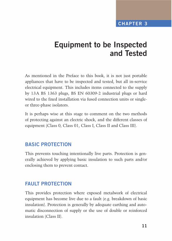
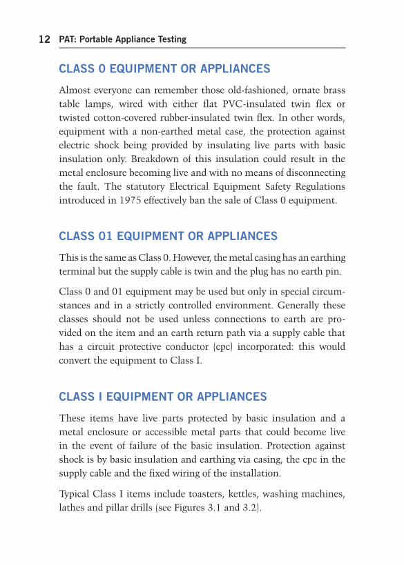
CLASS I EQUIPMENT OR APPLIANCES
These items have live parts protected by basic insulation and a metal enclosure or accessible metal parts that could become live in the event of failure of the basic insulation. Protection against shock is by basic insulation and earthing via casing, the cpc in the supply cable and the fixed wiring of the installation.
Typical Class I items include toasters, kettles, washing machines, lathes and pillar drills (see Figures 3.1 and 3.2 ).
ch03-h8736.indd 12ch03-h8736.indd 12 4/22/2008 10:31:53 AM4/22/2008 10:31:53 AM
Equipment to be Inspected and Tested 13
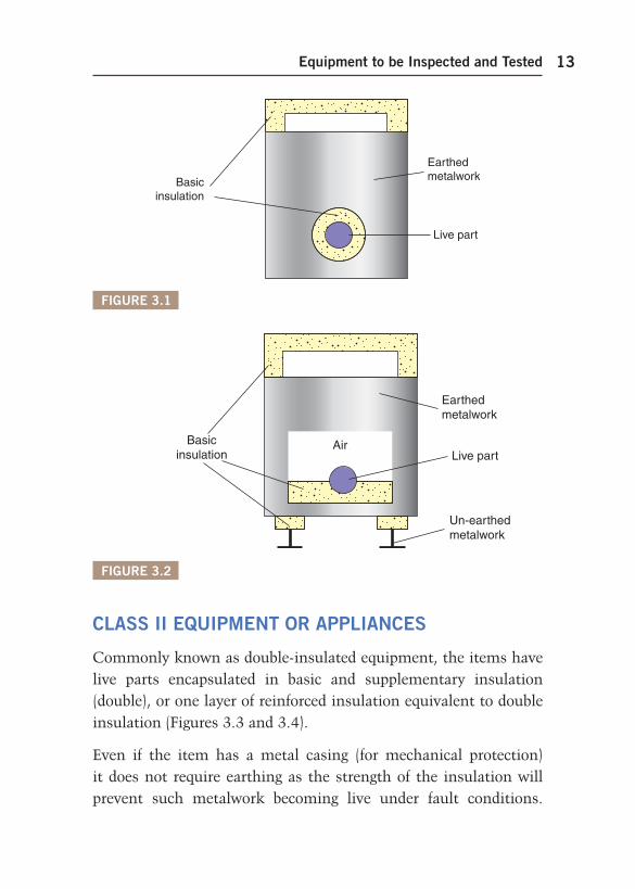
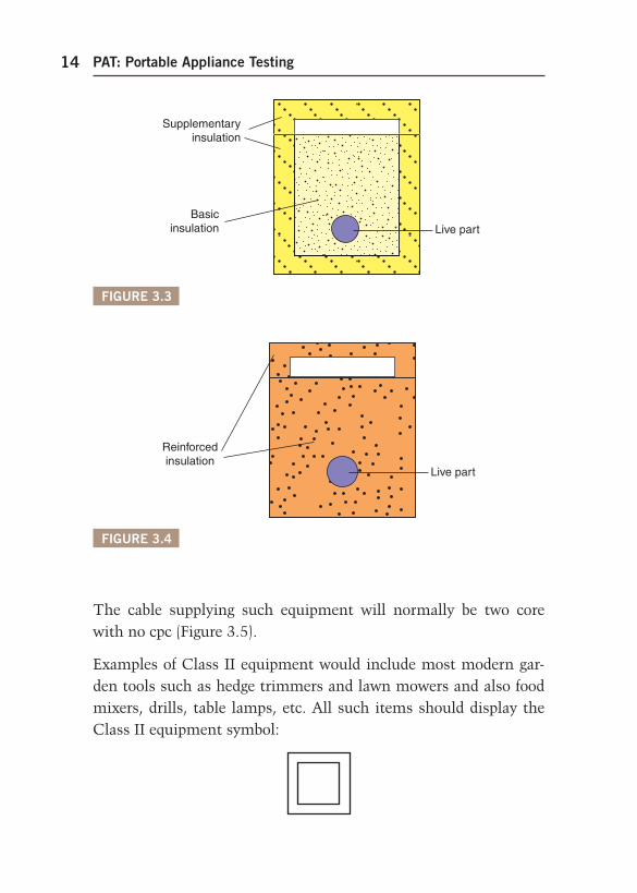
CLASS II EQUIPMENT OR APPLIANCES
Commonly known as double-insulated equipment, the items have live parts encapsulated in basic and supplementary insulation (double), or one layer of reinforced insulation equivalent to double insulation ( Figures 3.3 and 3.4 ).
Even if the item has a metal casing (for mechanical protection) it does not require earthing as the strength of the insulation will prevent such metalwork becoming live under fault conditions.
FIGURE 3.1
EarthedmetalworkBasic
insulation
Live part
FIGURE 3.2
Earthedmetalwork
Un-earthedmetalwork
Basicinsulation Live part
Air
ch03-h8736.indd 13ch03-h8736.indd 13 4/22/2008 10:31:53 AM4/22/2008 10:31:53 AM
PAT: Portable Appliance Testing14
The cable supplying such equipment will normally be two core with no cpc ( Figure 3.5 ).
Examples of Class II equipment would include most modern gar-den tools such as hedge trimmers and lawn mowers and also food mixers, drills, table lamps, etc. All such items should display the Class II equipment symbol:
FIGURE 3.3
Supplementaryinsulation
Basicinsulation Live part
FIGURE 3.4
Reinforcedinsulation
Live part
ch03-h8736.indd 14ch03-h8736.indd 14 4/22/2008 10:31:53 AM4/22/2008 10:31:53 AM
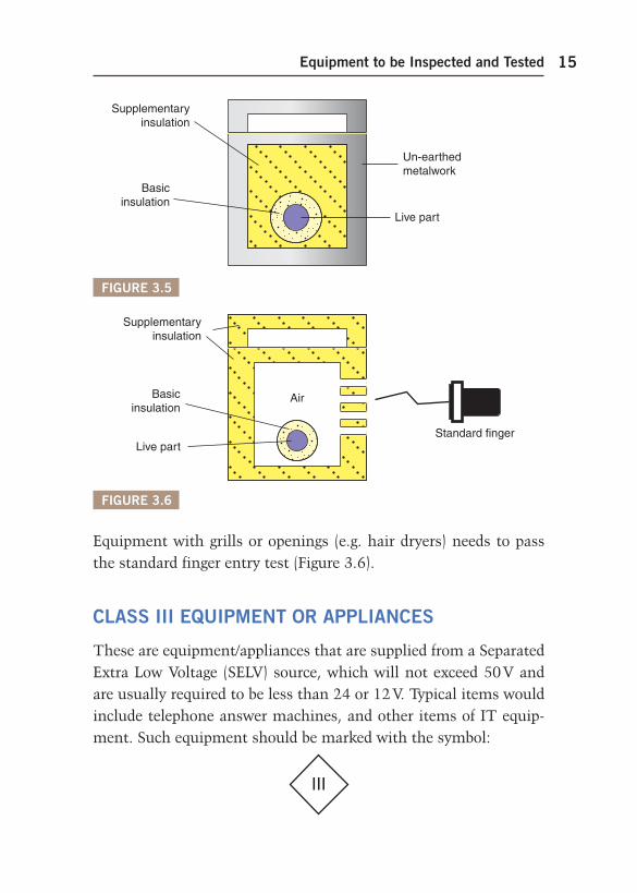
Equipment to be Inspected and Tested 15
Equipment with grills or openings (e.g. hair dryers) needs to pass the standard finger entry test ( Figure 3.6 ).
CLASS III EQUIPMENT OR APPLIANCES
These are equipment/appliances that are supplied from a Separated Extra Low Voltage (SELV) source, which will not exceed 50 V and are usually required to be less than 24 or 12 V. Typical items would include telephone answer machines, and other items of IT equip-ment. Such equipment should be marked with the symbol:
III
FIGURE 3.5
Supplementaryinsulation
Basicinsulation
Live part
Un-earthedmetalwork
FIGURE 3.6
Supplementaryinsulation
Basicinsulation
Live partStandard finger
Air
ch03-h8736.indd 15ch03-h8736.indd 15 4/22/2008 10:31:54 AM4/22/2008 10:31:54 AM
PAT: Portable Appliance Testing16
and be supplied from a safety isolating transformer to BS EN 61558-2, which in itself should be marked with the symbol:
These transformers are common and are typical of the type used for charging mobile phones, etc. Note there are no earths in an SELV system and hence the earth pin on the transformer is plastic.
EQUIPMENT TYPES
The Code of Practice for In-Service and Testing of Electrical Equipment defines various types of equipment/accessory that needs to be inspected and tested and that are generally in normal use. Advice from the manufacturer should be sought before testing spe-cialist equipment. The equipment types are as follows:
portable equipment/appliances hand-held equipment/appliances moveable equipment/appliances stationary equipment/appliances fixed equipment/appliances built-in equipment/appliances information technology equipment extension leads.
Portable equipment/appliances
These are items which are capable of easy movement whilst ener-gized and/or in operation. Examples of such appliances are:
chip fryers toasters coffee percolators tin openers.
ch03-h8736.indd 16ch03-h8736.indd 16 4/22/2008 10:31:54 AM4/22/2008 10:31:54 AM
Equipment to be Inspected and Tested 17
Hand-held equipment/appliances
These items are of a portable nature, which require control/use by direct hand contact. Examples include:
drills hair dryers hedge trimmers soldering irons.
Moveable equipment/appliances
There is a thin dividing line between this and the previous two types, but in any case still needs inspecting and testing. Generally such items are 18 kg or less and may have wheels or are easily moved. Examples would include:
tumble dryers the old-fashioned twin-tub washing machine industrial/commercial kitchen equipment.
Stationary equipment/appliances
These appliances weigh in excess of 18 kg and are not intended to be moved, such as:
ordinary cookers dishwashers washing machines.
Fixed equipment/appliances
These items are fixed or secured in place, typically:
tubular heaters lathes and other industrial equipment towel rails.
ch03-h8736.indd 17ch03-h8736.indd 17 4/22/2008 10:31:54 AM4/22/2008 10:31:54 AM
PAT: Portable Appliance Testing18
Built-in equipment/appliances
These are appliances that are ‘ built-in ’ to a unit or recess, such as:
an oven an inset electric fire.
Information technology equipment
In general terms, these are business equipment such as:
PCs printers typewriters scanners.
Extension leads
These include the multi-way sockets so very often used where IT equipment is present, as there is seldom enough fixed socket out-lets to supply all the various units. These leads should always be wired with three-core (line, neutral and earth) cable, and should not exceed:
12 m in length for a 1.25 mm 2 core size 15 m in length for a 1.5 mm 2 core size 25 m in length for a 2.5 mm 2 core size.
The 2.5 mm 2 lead should be supplied via a BS EN 60309-2 plug, and if any of the lengths are exceeded, the leads should be pro-tected by a BS 7071 30 mA RCD.
ch03-h8736.indd 18ch03-h8736.indd 18 4/22/2008 10:31:54 AM4/22/2008 10:31:54 AM
19
Inspection
Inspection is vital, and must precede testing. It may reveal serious defects which may not be detected by testing only.
Two types of inspection are required: user checks and formal visual inspection.
USER CHECKS
All employees are required by the Electricity at Work Regulations to work safely with electrical appliances/equipment and hence all should receive some basic training/instruction in the checking of equipment before use. (This training needs to be only of a short duration.) Generally, this is all common sense: nevertheless, a set routine of pre-use checks should be established. Such a routine could be as follows:
Check the condition of the appliance/equipment (look for cracks or damage).
Examine the cable supplying the item, looking for cuts, abrasions, cracks, etc.
Check the cable sheath is secure in the plug and the appliance.
Look for signs of overheating.
Check that it has a valid label indicating that it has been formally inspected and tested and the date of the next inspection and/or test.
CHAPTER 4
ch04-h8736.indd 19ch04-h8736.indd 19 4/22/2008 10:40:09 AM4/22/2008 10:40:09 AM
PAT: Portable Appliance Testing20
Decide if the item is suitable for the environment in which it is to be used, for example 230 V appliances should not be used on a construction site, unless protected by a 30 mA RCD.
If all these checks prove satisfactory, check that the appliance is working correctly.
If the user feels that the equipment is not satisfactory, it must be switched off, removed from the supply, labelled ‘ Not to be used ’ or words to that effect, and reported to a responsible person. That per-son will then take the necessary action to record the details of the faulty item and arrange for remedial work or have it disposed of.
No record of user checks is required if the equipment is considered satisfactory.
FORMAL VISUAL INSPECTION
This must be carried out by a person competent to do so, and recorded on an appropriate form. This inspection is similar to, but more detailed than, user checks and must be conducted with the accessory/equipment disconnected from the supply.
General
Check cable runs to ensure that cables will not be damaged by staff or heavy equipment.
Make sure that plugs, sockets, flex outlets, isolators, etc., are always accessible to enable disconnection/isolation of the supply, either for functional, maintenance or emergency purposes. For example, in many office environments, socket outlets are very often obscured by filing cabinets, etc.
ch04-h8736.indd 20ch04-h8736.indd 20 4/22/2008 10:40:09 AM4/22/2008 10:40:09 AM
Inspection 21
Check that items that require clear ventilation, such as convector heaters, VDUs, etc., are not covered in paper, files, etc., and that foreign bodies or moisture cannot accidentally enter such equipment.
Ensure that cables exiting from plugs or equipment are not tightly bent.
Check that multi-way adaptors/extension leads are not excessively used.
Check that equipment is suitable for both the purpose to which it is being put and the environment in which it is being used.
Ensure that accessories/equipment are disconnected from the supply during the inspection process, either by removing the plug or by switching off at a connection unit or isolator.
Take great care before isolating or switching off business equipment. Ensure that a responsible person agrees that this may be done, otherwise this may result in a serious loss of information, working processes, etc.
The accessories/equipment
Check the cable for damage. Is it too long or too short?
Is the supply cable/cord to the appliance the right size?
Is the plug damaged? Look for signs of overheating, etc.
Is the fuse in a BS 1363 13 A plug the correct size? Are the contacts for the fuse secure? This requires dismantling of the plug. The fuse should be approved, and ideally have an ASTA mark on it. Some fuses made in China and marked PMS are dangerous and should be replaced. Fuse and cord
ch04-h8736.indd 21ch04-h8736.indd 21 4/22/2008 10:40:09 AM4/22/2008 10:40:09 AM
PAT: Portable Appliance Testing22
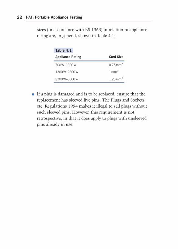
sizes (in accordance with BS 1363) in relation to appliance rating are, in general, shown in Table 4.1 :
Table 4.1
Appliance Rating Cord Size
700 W–1300 W 0.75 mm 2
1300 W–2300 W 1 mm 2
2300 W–3000 W 1.25 mm 2
If a plug is damaged and is to be replaced, ensure that the replacement has sleeved live pins. The Plugs and Sockets etc. Regulations 1994 makes it illegal to sell plugs without such sleeved pins. However, this requirement is not retrospective, in that it does apply to plugs with unsleeved pins already in use.
ch04-h8736.indd 22ch04-h8736.indd 22 4/22/2008 10:40:09 AM4/22/2008 10:40:09 AM
23
Combined Inspection and Testing
Combined inspection and testing comprises preliminary inspec-tion as per Chapter 4 together with instrument tests to verify earth continuity, insulation resistance, functional checks and, in the case of cord sets and extension leads, polarity as well. In some low-risk environments such as offices, shops, hotels, etc., Class II equipment does not require the routine instrument tests.
TESTING
This has to be carried out with the appliance/equipment isolated from the supply. Such isolation is, of course, easy when the item is supplied via a plug and socket, but presents some difficulties if it is permanently wired to, say, a flex outlet, a connection unit, or an iso-lator, etc. In these cases the tester must be competent to undertake a disconnection of the appliance; if not, then a qualified/competent electrical operative should carry out the work.
Additionally, the permission of a responsible person may be needed before isolating/disconnecting business equipment.
PRELIMINARY INSPECTION
This must always be done before testing as it could reveal faults that testing may not show, such as unsecured cables in appliance
CHAPTER 5
Ch05-H8736.indd 23Ch05-H8736.indd 23 4/24/2008 5:12:50 PM4/24/2008 5:12:50 PM
PAT: Portable Appliance Testing24
housings, damaged cable sheathing, etc. The inspection procedure is as detailed in Chapter 4.
Testing
This may be carried out using a portable appliance tester, of which there are many varieties, or separate instruments capable of meas-uring continuity and insulation resistance.
Portable appliance testers
These instruments allow appliances, fitted with a plug, to be easily tested. Some testers have the facility for testing appliances of vari-ous voltage ranges, single and three phase, although the majority only accept single-phase 230 or 110 V plugs (BS 1363 and BS EN 60309-2).
Generally, portable appliance testers are designed to allow opera-tives to ‘ plug in ’ an item of equipment, push a test button, view results and note a ‘ pass ’ or ‘ fail ’ indication. The operative can then interpret these results and, where possible, make adjustments which may enable a ‘ fail ’ indication to be changed to a ‘ pass ’ status.
Some portable appliance testers are of the GO, NO-GO type, where the indication is either a red (fail) or green (pass) light. As there are no test figures associated with this type of tester, no adjustment can be made. This could result in appliances being rejected when no fault is present. This situation will be dealt with a little later.
Continuity/insulation resistance testers
These are usually dual instrument testers, although separate instruments are in use. Multi-meters are rarely suitable for these tests.
Ch05-H8736.indd 24Ch05-H8736.indd 24 4/24/2008 5:12:50 PM4/24/2008 5:12:50 PM
Combined Inspection and Testing 25
For earth continuity, the instrument test current (AC or DC) should be between 20 and 200 mA with the source having an open-circuit voltage of between 100 mV and 24 V. For insulation resistance the instrument should deliver a maintainable test voltage of 500 V DC across the load. Note : All test leads should conform to the recom-mendations of the HSE Guidance Note GS 38.
So, what are the details of the tests required?
Earth continuity
This test can only be applied to Class I equipment, and the pur-pose of the test is to ensure that the earth terminal of the item is connected to the casing effectively enough to result in the test between this terminal and the casing giving a value of not more than 0.1 Ω .
Clearly, it is not very practicable to have to access terminals inside an enclosure and hence it is reasonable to measure the earth conti-nuity from outside, via the plug and supply lead. This also checks the integrity of the lead earth conductor, or cpc.
Testing in this way will, of course, add the resistance of the lead to the appliance earth resistance, which could result in an overall value in excess of the 0.1 Ω limit, and the tester may indicate a ‘ fail ’ status. This is where the interpretation of results is so impor-tant in that, provided the final value having subtracted the lead resistance from the instrument reading is no more than 0.1 Ω , the appliance can be passed as satisfactory.
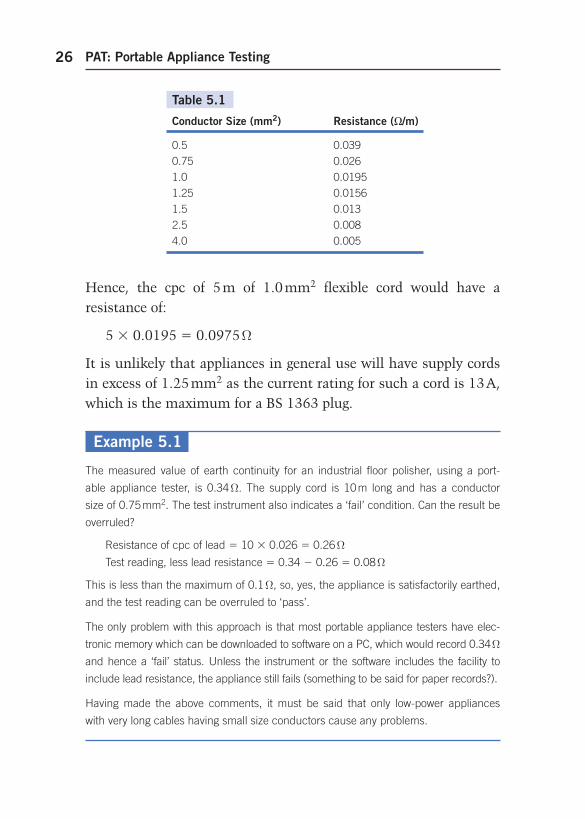
The use of a GO, NO-GO instrument prohibits such an adjust-ment as there are no test values available. Table 5.1 gives the resistance in ohms per metre of copper conductors, at 20°C for flexible cords from 0.5 to 4.0 mm 2 .
Ch05-H8736.indd 25Ch05-H8736.indd 25 4/24/2008 5:12:51 PM4/24/2008 5:12:51 PM
PAT: Portable Appliance Testing26
Hence, the cpc of 5 m of 1.0 mm 2 flexible cord would have a resistance of:
5 0.0195 0.0975 Ω
It is unlikely that appliances in general use will have supply cords in excess of 1.25 mm 2 as the current rating for such a cord is 13 A, which is the maximum for a BS 1363 plug.
Table 5.1
Conductor Size (mm 2 ) Resistance ( /m)
0.5 0.039
0.75 0.026
1.0 0.0195
1.25 0.0156
1.5 0.013
2.5 0.008
4.0 0.005
Example 5.1
The measured value of earth continuity for an industrial floor polisher, using a port-
able appliance tester, is 0.34 Ω . The supply cord is 10 m long and has a conductor
size of 0.75 mm 2 . The test instrument also indicates a ‘ fail ’ condition. Can the result be
overruled?
Resistance of cpc of lead 10 0.026 0.26 Ω
Test reading, less lead resistance 0.34 0.26 0.08 Ω
This is less than the maximum of 0.1 Ω , so, yes, the appliance is satisfactorily earthed,
and the test reading can be overruled to ‘ pass ’ .
The only problem with this approach is that most portable appliance testers have elec-
tronic memory which can be downloaded to software on a PC, which would record 0.34 Ω
and hence a ‘ fail ’ status. Unless the instrument or the software includes the facility to
include lead resistance, the appliance still fails (something to be said for paper records?).
Having made the above comments, it must be said that only low-power appliances
with very long cables having small size conductors cause any problems.
Ch05-H8736.indd 26Ch05-H8736.indd 26 4/24/2008 5:12:51 PM4/24/2008 5:12:51 PM
Combined Inspection and Testing 27
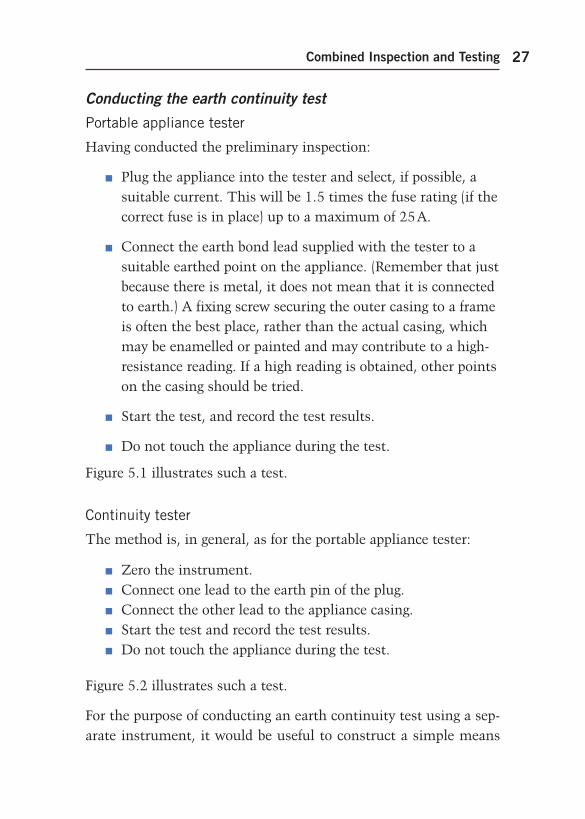
Conducting the earth continuity test
Portable appliance tester
Having conducted the preliminary inspection:
Plug the appliance into the tester and select, if possible, a suitable current. This will be 1.5 times the fuse rating (if the correct fuse is in place) up to a maximum of 25 A.
Connect the earth bond lead supplied with the tester to a suitable earthed point on the appliance. (Remember that just because there is metal, it does not mean that it is connected to earth.) A fixing screw securing the outer casing to a frame is often the best place, rather than the actual casing, which may be ename l led or painted and may contribute to a high-resistance reading. If a high reading is obtained, other points on the casing should be tried.
Start the test, and record the test results.
Do not touch the appliance during the test.
Figure 5.1 illustrates such a test.
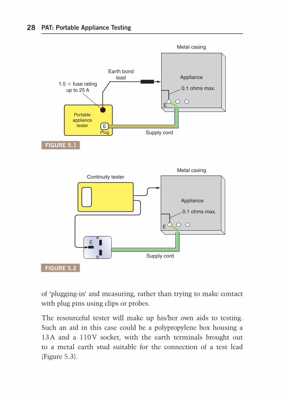
Continuity tester
The method is, in general, as for the portable appliance tester:
Zero the instrument. Connect one lead to the earth pin of the plug. Connect the other lead to the appliance casing. Start the test and record the test results. Do not touch the appliance during the test.
Figure 5.2 illustrates such a test.
For the purpose of conducting an earth continuity test using a sep-arate instrument, it would be useful to construct a simple means
Ch05-H8736.indd 27Ch05-H8736.indd 27 4/24/2008 5:12:51 PM4/24/2008 5:12:51 PM
PAT: Portable Appliance Testing28
of ‘ plugging-in ’ and measuring, rather than trying to make contact with plug pins using clips or probes.
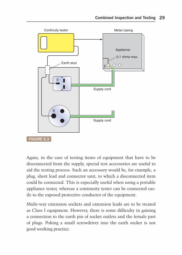
The resourceful tester will make up his/her own aids to testing. Such an aid in this case could be a polypropylene box housing a 13 A and a 110 V socket, with the earth terminals brought out to a metal earth stud suitable for the connection of a test lead ( Figure 5.3 ).
FIGURE 5.1
Metal casing
Earth bondlead
Supply cordPlug
Portableappliance
tester
E
0.1 ohms max.
Appliance1.5 fuse rating
up to 25 A
E
FIGURE 5.2
E
Continuity testerMetal casing
Supply cord
E
0.1 ohms max.
Appliance
Ch05-H8736.indd 28Ch05-H8736.indd 28 4/24/2008 5:12:51 PM4/24/2008 5:12:51 PM
Combined Inspection and Testing 29
Again, in the case of testing items of equipment that have to be disconnected from the supply, special test accessories are useful to aid the testing process. Such an accessory would be, for example, a plug, short lead and connector unit, to which a disconnected item could be connected. This is especially useful when using a portable appliance tester, whereas a continuity tester can be connected eas-ily to the exposed protective conductor of the equipment.
Multi-way extension sockets and extension leads are to be treated as Class I equipment. However, there is some difficulty in gaining a connection to the earth pin of socket outlets and the female part of plugs. Poking a small screwdriver into the earth socket is not good working practice.
FIGURE 5.3
Continuity tester Metal casing
Supply cord
Supply cord
E
0.1 ohms max.
Appliance
E
E
Earth stud
Ch05-H8736.indd 29Ch05-H8736.indd 29 4/24/2008 5:12:51 PM4/24/2008 5:12:51 PM
PAT: Portable Appliance Testing30
For Class I cord sets, why not use the arrangement shown in Figure 5.3 and add a selection of recessed sockets to house the range of female plugs found on cord sets? All their earth pins would be connected to the earth stud. For extension leads incor-porating a socket or sockets, use the earth pin from an old plug, as this is designed to enter the earth pin socket.
Insulation resistance
Realistically, this test can only be carried out on Class I equip-ment. It is made to ensure that there is no breakdown of insula-tion between the protective earth and live (line and neutral) parts of the appliance and its lead.
For Class II items, there are no earthed parts and one test probe would need to be placed at various points on the body of the appli-ance in order to check the integrity of the casing.
Items that have a cord set (e.g. a kettle) should have the cord set plugged into the appliance and the appliance switch should be in the ‘ on ’ position.
There are two tests that can be made, using either the applied volt-age method or the earth leakage method.
The applied voltage method
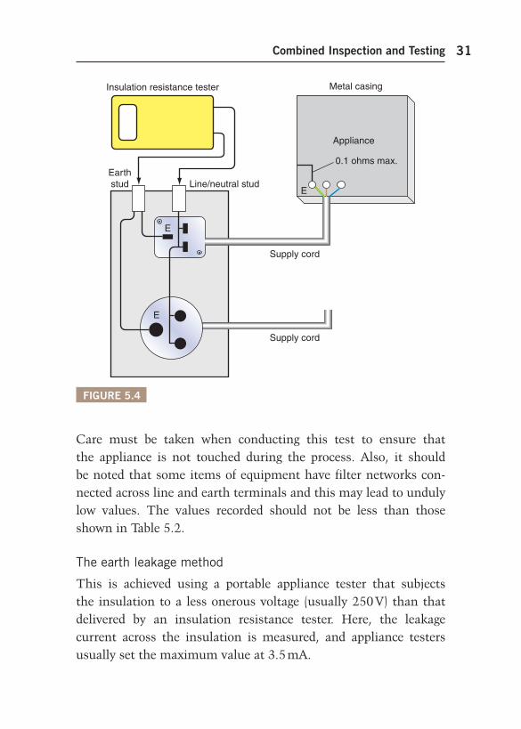
This is conducted using an insulation resistance tester, set on 500 V DC. The test is made between the line and neutral con-nected together , and the protective earth. (For three-phase items, all live conductors are connected together.) This is best achieved using the same arrangement as shown in Figure 5.2 , but with the addition of a line/neutral stud connected to the socket’s line and neutral ( Figure 5.4 ).
Ch05-H8736.indd 30Ch05-H8736.indd 30 4/24/2008 5:12:51 PM4/24/2008 5:12:51 PM
Combined Inspection and Testing 31
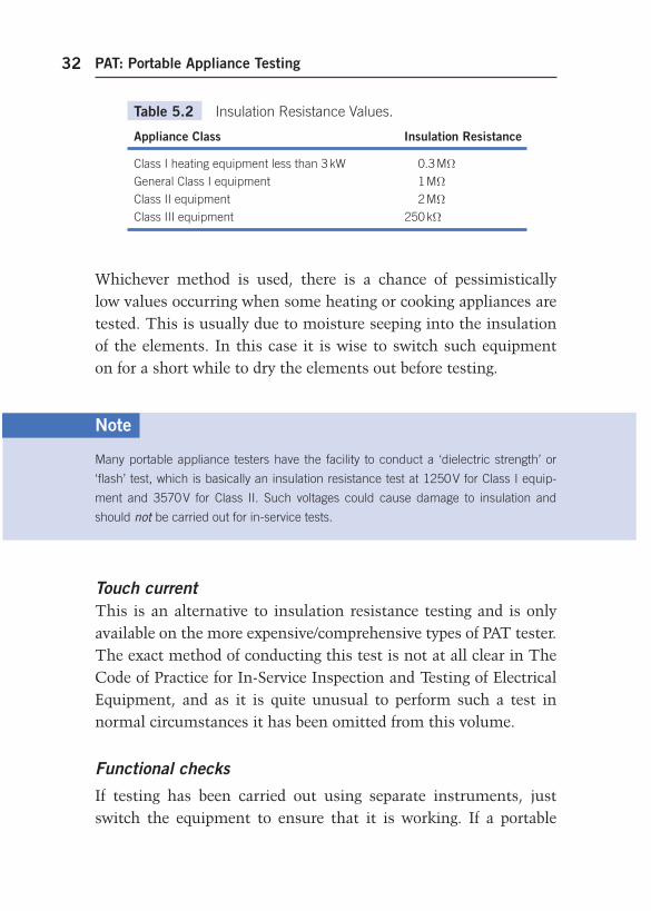
Care must be taken when conducting this test to ensure that the appliance is not touched during the process. Also, it should be noted that some items of equipment have filter networks con-nected across line and earth terminals and this may lead to unduly low values. The values recorded should not be less than those shown in Table 5.2 .
The earth leakage method
This is achieved using a portable appliance tester that subjects the insulation to a less onerous voltage (usually 250 V) than that delivered by an insulation resistance tester. Here, the leakage current across the insulation is measured, and appliance testers usually set the maximum value at 3.5 mA.
FIGURE 5.4
Insulation resistance tester Metal casing
Line/neutral studEarthstud
Supply cord
Supply cord
E
0.1 ohms max.
Appliance
E
E
Ch05-H8736.indd 31Ch05-H8736.indd 31 4/24/2008 5:12:51 PM4/24/2008 5:12:51 PM
PAT: Portable Appliance Testing32
Whichever method is used, there is a chance of pessimistically low values occurring when some heating or cooking appliances are tested. This is usually due to moisture seeping into the insulation of the elements. In this case it is wise to switch such equipment on for a short while to dry the elements out before testing.
Table 5.2 Insulation Resistance Values.
Appliance Class Insulation Resistance
Class I heating equipment less than 3 kW 0.3 M Ω
General Class I equipment 1 M Ω
Class II equipment 2 M Ω
Class III equipment 250 k Ω
Note
Many portable appliance testers have the facility to conduct a ‘ dielectric strength ’ or
‘ flash ’ test, which is basically an insulation resistance test at 1250 V for Class I equip-
ment and 3570 V for Class II. Such voltages could cause damage to insulation and
should not be carried out for in-service tests.
Touch current This is an alternative to insulation resistance testing and is only available on the more expensive/comprehensive types of PAT tester. The exact method of conducting this test is not at all clear in The Code of Practice for In-Service Inspection and Testing of Electrical Equipment, and as it is quite unusual to perform such a test in normal circumstances it has been omitted from this volume.
Functional checks
If testing has been carried out using separate instruments, just switch the equipment to ensure that it is working. If a portable
Ch05-H8736.indd 32Ch05-H8736.indd 32 4/24/2008 5:12:52 PM4/24/2008 5:12:52 PM
Combined Inspection and Testing 33
appliance tester is used, there is usually a facility for conducting a ‘ load test ’ . The equipment is automatically switched on and the power consumption measured while the item is on load. This is useful as it indicates if the equipment is working to its full capac-ity, for example a 2 kW reading on a 3 kW heater suggests a broken element.
Ch05-H8736.indd 33Ch05-H8736.indd 33 4/24/2008 5:12:52 PM4/24/2008 5:12:52 PM

Ch05-H8736.indd 34Ch05-H8736.indd 34 4/24/2008 5:12:52 PM4/24/2008 5:12:52 PM
35
Appendix 1 Shock Risk
As we have seen in Chapter 1, all who are involved with electri-cal systems are ‘ Duty holders ’ in Law. For those operatives who have only a limited knowledge of electricity, but are nevertheless charged with their company’s appliance testing, an understanding of electric shock will help to give more meaning and confidence to the inspection and test process.
ELECTRIC SHOCK
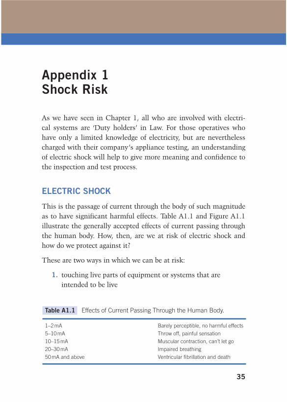
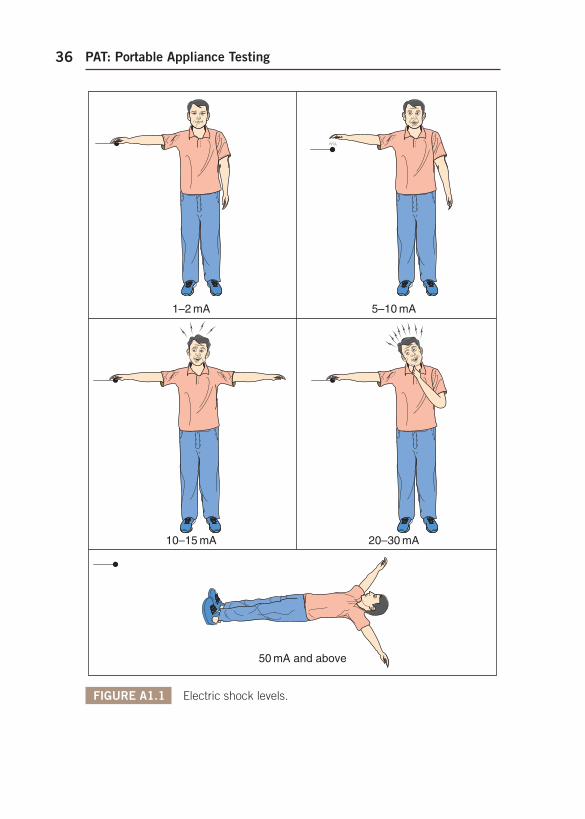
This is the passage of current through the body of such magnitude as to have significant harmful effects. Table A1.1 and Figure A1.1 illustrate the generally accepted effects of current passing through the human body. How, then, are we at risk of electric shock and how do we protect against it?
These are two ways in which we can be at risk:
1. touching live parts of equipment or systems that are intended to be live
Table A1.1 Effects of Current Passing Through the Human Body.
1–2 mA Barely perceptible, no harmful effects
5–10 mA Throw off, painful sensation
10–15 mA Muscular contraction, can’t let go
20–30 mA Impaired breathing
50 mA and above Ventricular fibrillation and death
APP-1-H8736.indd 35APP-1-H8736.indd 35 4/24/2008 5:14:46 PM4/24/2008 5:14:46 PM
PAT: Portable Appliance Testing36
FIGURE A1.1 Electric shock levels.
1–2 mA 5–10 mA
10–15 mA 20–30 mA
50 mA and above
APP-1-H8736.indd 36APP-1-H8736.indd 36 4/24/2008 5:14:46 PM4/24/2008 5:14:46 PM
Appendix 1: Shock Risk 37
2. touching conductive parts which are not meant to be live, but which have become live due to a fault.
The conductive parts associated with point 2 above can be either a metalwork of electrical equipment and accessories (Class I) and that of electrical wiring systems (e.g. metal conduit and trunking), called exposed conductive parts, or other metalwork (e.g. pipes, radiators and girders), called extraneous conductive parts.
BASIC PROTECTION
How can we prevent danger to persons and livestock from contact with intentionally live parts? Clearly we must minimize the risk of such contact and this can be achieved by basic protection, which comprises:
insulating any live parts ensuring any uninsulated live parts are housed in suitable
enclosures and/or are behind barriers.
The use of a residual current device (RCD) cannot prevent such con-tact, but it can be used as additional protection to any of the other measures taken, provided that it is rated at 30 mA or less and has a tripping time of not more than 40 ms at an operating current of 150 mA.
It should be noted that RCDs are not the panacea for all electrical ills, they can malfunction, but they are a valid and effective back-up to the other methods. They must not be used as the sole means of protection.
FAULT PROTECTION
How, under single fault conditions, can we protect against shock from contact with live, exposed or extraneous conductive parts
APP-1-H8736.indd 37APP-1-H8736.indd 37 4/24/2008 5:14:46 PM4/24/2008 5:14:46 PM
PAT: Portable Appliance Testing38
whilst touching earth, or from contact between live exposed and/or extraneous conductive parts? The most common method is by protective earthing and protective equipotential bonding and auto-matic disconnection of supply.
All extraneous conductive parts are joined together with a main protective bonding conductor and connected to the main earthing terminal, and all exposed conductive parts are connected to the main earthing terminal by the circuit protective conductors. Add to this, overcurrent protection that will operate fast enough when a fault occurs and the risk of severe electric shock is significantly reduced.
WHAT IS EARTH AND WHY AND HOW WE CONNECT TO IT?
The thin layer of material which covers our planet – rock, clay, chalk or whatever – is what we in the world of electricity refer to as earth. So, why do we need to connect anything to it? After all, it is not as if earth is a good conductor.
It might be wise at this stage to investigate potential difference (PD). A PD is exactly what it says it is: a difference in potential (volts). In this way, two conductors having PDs of, say, 20 and 26 V have a PD between them of 26 20 6 V. The original PDs (i.e. 20 and 26 V) are the PDs between 20 V and 0 V and 26 V and 0 V. So where does this 0 V or zero potential come from? The sim-ple answer is, in our case, the earth. The definition of earth is, therefore, the conductive mass of earth, whose electric potential at any point is conventionally taken as zero.
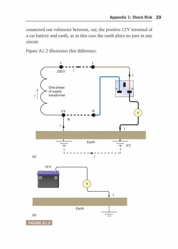
Thus, if we connect a voltmeter between a live part (e.g. the line conductor of a socket outlet) and earth, we may read 230 V; the conductor is at 230 V and the earth at zero. The earth provides a path to complete the circuit. We would measure nothing at all if we
APP-1-H8736.indd 38APP-1-H8736.indd 38 4/24/2008 5:14:46 PM4/24/2008 5:14:46 PM
Appendix 1: Shock Risk 39
connected our voltmeter between, say, the positive 12 V terminal of a car battery and earth, as in this case the earth plays no part in any circuit.
Figure A1.2 illustrates this difference.
FIGURE A1.2
L
230 V
I
I
One phaseof supplytransformer
L
N
N
0 V
0 VEarth
I
I
I
I
(a)
V
V
12 V
I
Earth
(b)
APP-1-H8736.indd 39APP-1-H8736.indd 39 4/24/2008 5:14:46 PM4/24/2008 5:14:46 PM
PAT: Portable Appliance Testing40
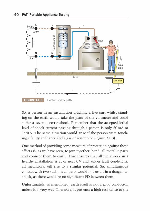
So, a person in an installation touching a live part whilst stand-ing on the earth would take the place of the voltmeter and could suffer a severe electric shock. Remember that the accepted lethal level of shock current passing through a person is only 50 mA or 1/20 A. The same situation would arise if the person were touch-ing a faulty appliance and a gas or water pipe ( Figure A1.3 ).
One method of providing some measure of protection against these effects is, as we have seen, to join together (bond) all metallic parts and connect them to earth. This ensures that all metalwork in a healthy installation is at or near 0 V and, under fault conditions, all metalwork will rise to a similar potential. So, simultaneous contact with two such metal parts would not result in a dangerous shock, as there would be no significant PD between them.
Unfortunately, as mentioned, earth itself is not a good conductor, unless it is very wet. Therefore, it presents a high resistance to the
FIGURE A1.3 Electric shock path.
N
Gaspipe
Earth
I
Fault
NN
0 V
230 V
Con
sum
er u
nit
I
II
ILL
Supply
Gas main
APP-1-H8736.indd 40APP-1-H8736.indd 40 4/24/2008 5:14:46 PM4/24/2008 5:14:46 PM
Appendix 1: Shock Risk 41
flow of fault current. This resistance is usually enough to restrict fault current to a level well below that of the rating of the protec-tive device, leaving a faulty circuit uninterrupted. Clearly this is an unhealthy situation.
In all but the most rural areas, consumers can connect to a metal-lic earth return conductor, which is ultimately connected to the earthed neutral of the supply. This, of course, presents a low-resistance path for fault currents to operate the protection.
In summary, connecting metalwork to earth places that metal at or near zero potential and bonding between metallic parts puts such parts at a similar potential even under fault conditions. Add to this a low-resistance earth fault return path, which will enable the circuit protection to operate very fast, and we have signifi-cantly reduced the risk of electric shock. We can see from this how important it is to check that equipment earthing is satisfactory and that there is no damage to conductor insulation.
APP-1-H8736.indd 41APP-1-H8736.indd 41 4/24/2008 5:14:47 PM4/24/2008 5:14:47 PM

APP-1-H8736.indd 42APP-1-H8736.indd 42 4/24/2008 5:14:47 PM4/24/2008 5:14:47 PM
43
Appendix 2 Basic Electrical Theory Revision
This appendix has been added in order to jog the memory of those who have some electrical background and to offer a basic explana-tion of theory topics within this book for those relatively new to the subject.
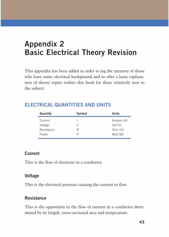
ELECTRICAL QUANTITIES AND UNITS
Quantity Symbol Units
Current I Ampere (A)
Voltage V Volt (V)
Resistance R Ohm (Ω )
Power P Watt (W)
Current
This is the flow of electrons in a conductor.
Voltage
This is the electrical pressure causing the current to flow.
Resistance
This is the opposition to the flow of current in a conductor deter-mined by its length, cross-sectional area and temperature.
app-2-h8736.indd 43app-2-h8736.indd 43 4/22/2008 10:51:01 AM4/22/2008 10:51:01 AM

PAT: Portable Appliance Testing44
Power
This is the product of current and voltage, hence P I V .
RELATIONSHIP BETWEEN VOLTAGE, CURRENT AND RESISTANCE
Voltage Current Resistance V I R , Current Voltage/Resistance I V / R or Resistance Voltage/Current R V / I .
COMMON MULTIPLES OF UNITS
Current I amperes kA mA
Kilo-amperes Milli-amperes
1000 amperes 1/1000 of an ampere
Voltage V volts kV mV
Kilovolts Millivolts
1000 volts 1/1000 of a volt
Resistance R ohms M Ω m Ω
Megohms Milli-ohms
1 000 000 ohms 1/1000 of an ohm
Power P watts MW kW
Megawatt Kilowatt
1 000 000 watts 1000 watts
RESISTANCE IN SERIES
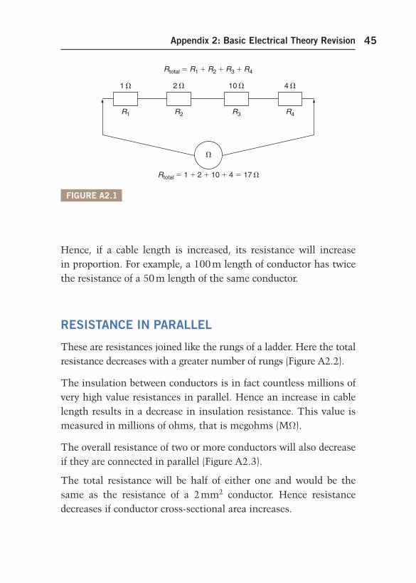
These are resistances joined end to end in the form of a chain. The total resistance increases as more resistances are added ( Figure A2.1 ).
app-2-h8736.indd 44app-2-h8736.indd 44 4/22/2008 10:51:01 AM4/22/2008 10:51:01 AM
Appendix 2: Basic Electrical Theory Revision 45
Hence, if a cable length is increased, its resistance will increase in proportion. For example, a 100 m length of conductor has twice the resistance of a 50 m length of the same conductor.
RESISTANCE IN PARALLEL
These are resistances joined like the rungs of a ladder. Here the total resistance decreases with a greater number of rungs ( Figure A2.2 ).
The insulation between conductors is in fact countless millions of very high value resistances in parallel. Hence an increase in cable length results in a decrease in insulation resistance. This value is measured in millions of ohms, that is megohms (M Ω ).
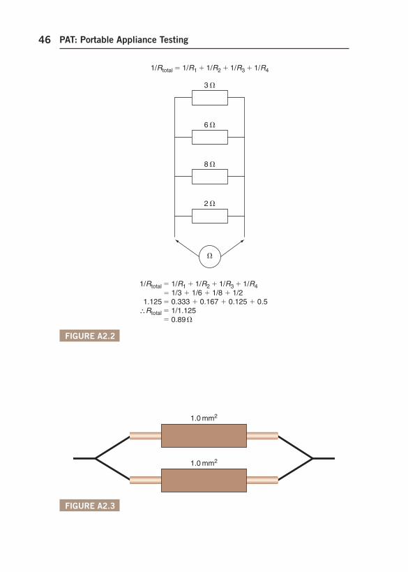
The overall resistance of two or more conductors will also decrease if they are connected in parallel ( Figure A2.3 ).
The total resistance will be half of either one and would be the same as the resistance of a 2 mm 2 conductor. Hence resistance decreases if conductor cross-sectional area increases.
Rtotal R1 R2 R3 R4
Rtotal 1 2 10 4 17
1 2 10 4
R1 R2 R3 R4
FIGURE A2.1
app-2-h8736.indd 45app-2-h8736.indd 45 4/22/2008 10:51:01 AM4/22/2008 10:51:01 AM
PAT: Portable Appliance Testing46
FIGURE A2.2
1/Rtotal 1/R1 1/R2 1/R3 1/R4
3
6
2
8
1/Rtotal 1/R1 1/R2 1/R3 1/R4 1/3 1/6 1/8 1/2 1.125 0.333 0.167 0.125 0.5 Rtotal 1/1.125
0.89
FIGURE A2.3
1.0 mm2
1.0 mm2
app-2-h8736.indd 46app-2-h8736.indd 46 4/22/2008 10:51:01 AM4/22/2008 10:51:01 AM
Appendix 2: Basic Electrical Theory Revision 47
Example A2.1
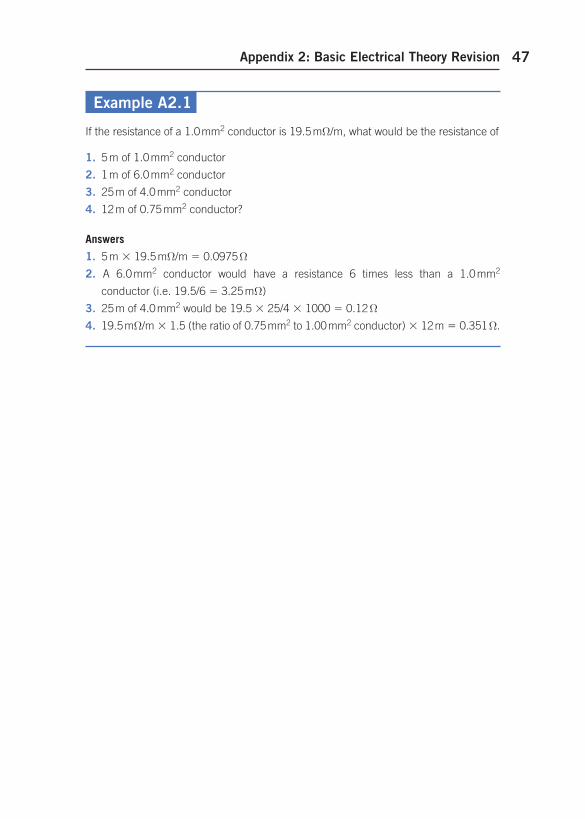
If the resistance of a 1.0 mm 2 conductor is 19.5 m Ω /m, what would be the resistance of
1. 5 m of 1.0 mm 2 conductor
2. 1 m of 6.0 mm 2 conductor
3. 25 m of 4.0 mm 2 conductor
4. 12 m of 0.75 mm 2 conductor?
Answers
1. 5 m 19.5 m Ω /m 0.0975 Ω
2. A 6.0 mm 2 conductor would have a resistance 6 times less than a 1.0 mm 2
conductor (i.e. 19.5/6 3.25 m Ω )
3. 25 m of 4.0 mm 2 would be 19.5 25/4 1000 0.12 Ω
4. 19.5 m Ω /m 1.5 (the ratio of 0.75 mm 2 to 1.0 0 mm 2 conductor) 12 m 0.351 Ω .
app-2-h8736.indd 47app-2-h8736.indd 47 4/22/2008 10:51:01 AM4/22/2008 10:51:01 AM

app-2-h8736.indd 48app-2-h8736.indd 48 4/22/2008 10:51:01 AM4/22/2008 10:51:01 AM
49
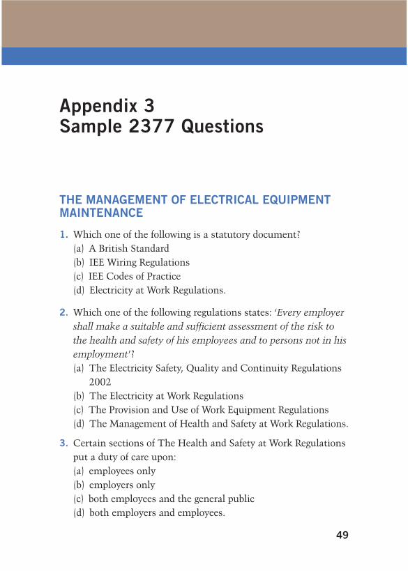
Appendix 3 Sample 2377 Questions
THE MANAGEMENT OF ELECTRICAL EQUIPMENT MAINTENANCE
1. Which one of the following is a statutory document? (a) A British Standard (b) IEE Wiring Regulations (c) IEE Codes of Practice (d) Electricity at Work Regulations.
2. Which one of the following regulations states: ‘ Every employer shall make a suitable and sufficient assessment of the risk to the health and safety of his employees and to persons not in his employment ’ ? (a) The Electricity Safety, Quality and Continuity Regulations
2002 (b) The Electricity at Work Regulations (c) The Provision and Use of Work Equipment Regulations (d) The Management of Health and Safety at Work Regulations.
3. Certain sections of The Health and Safety at Work Regulations put a duty of care upon: (a) employees only (b) employers only (c) both employees and the general public (d) both employers and employees.
app-3-h8736.indd 49app-3-h8736.indd 49 4/22/2008 10:52:24 AM4/22/2008 10:52:24 AM
PAT: Portable Appliance Testing50
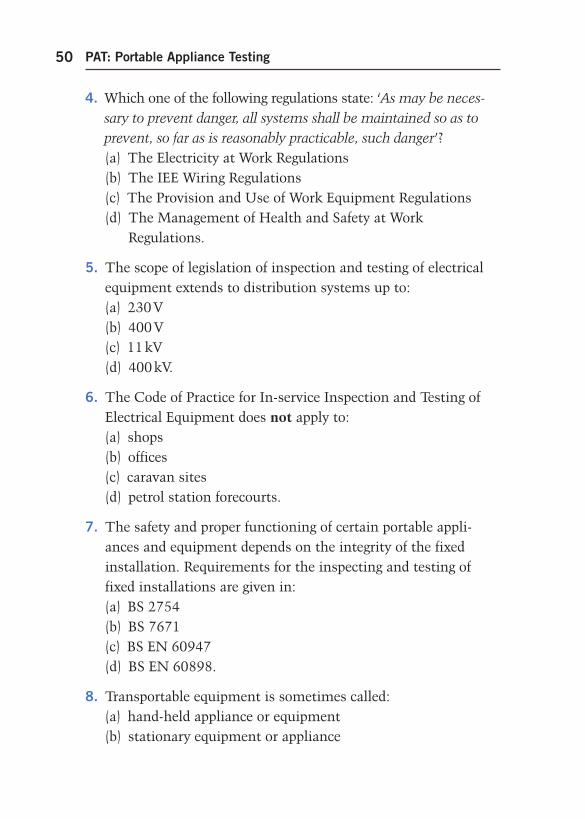
4. Which one of the following regulations state: ‘ As may be neces-sary to prevent danger, all systems shall be maintained so as to prevent, so far as is reasonably practicable, such danger ’ ? (a) The Electricity at Work Regulations (b) The IEE Wiring Regulations (c) The Provision and Use of Work Equipment Regulations (d) The Management of Health and Safety at Work
Regulations.
5. The scope of legislation of inspection and testing of electrical equipment extends to distribution systems up to: (a) 230 V (b) 400 V (c) 11 kV (d) 400 kV.
6. The Code of Practice for In-service Inspection and Testing of Electrical Equipment does not apply to: (a) shops (b) offices (c) caravan sites (d) petrol station forecourts.
7. The safety and proper functioning of certain portable appli-ances and equipment depends on the integrity of the fixed installation. Requirements for the inspecting and testing of fixed installations are given in: (a) BS 2754 (b) BS 7671 (c) BS EN 60947 (d) BS EN 60898.
8. Transportable equipment is sometimes called: (a) hand-held appliance or equipment (b) stationary equipment or appliance
app-3-h8736.indd 50app-3-h8736.indd 50 4/22/2008 10:52:24 AM4/22/2008 10:52:24 AM
Appendix 3: Sample 2377 Questions 51
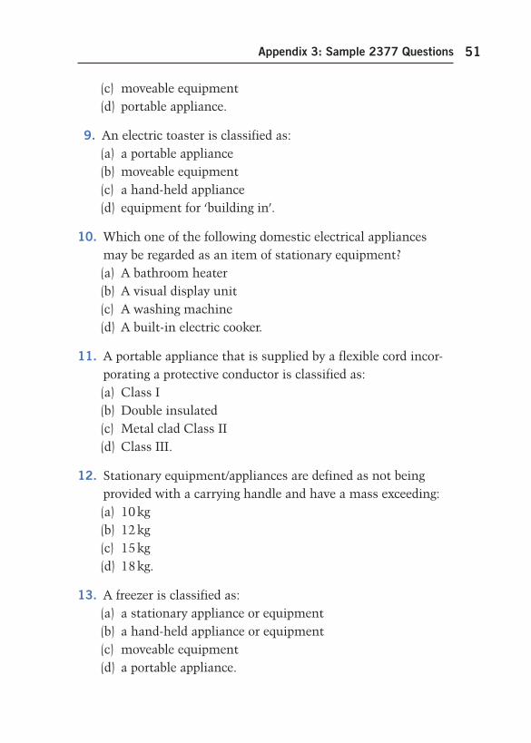
(c) moveable equipment (d) portable appliance.
9. An electric toaster is classified as: (a) a portable appliance (b) moveable equipment (c) a hand-held appliance (d) equipment for ‘ building in ’ .
10. Which one of the following domestic electrical appliances may be regarded as an item of stationary equipment? (a) A bathroom heater (b) A visual display unit (c) A washing machine (d) A built-in electric cooker.
11. A portable appliance that is supplied by a flexible cord incor-porating a protective conductor is classified as: (a) Class I (b) Double insulated (c) Metal clad Class II (d) Class III.
12. Stationary equipment/appliances are defined as not being provided with a carrying handle and have a mass exceeding: (a) 10 kg (b) 12 kg (c) 15 kg (d) 18 kg.
13. A freezer is classified as: (a) a stationary appliance or equipment (b) a hand-held appliance or equipment (c) moveable equipment (d) a portable appliance.
app-3-h8736.indd 51app-3-h8736.indd 51 4/22/2008 10:52:24 AM4/22/2008 10:52:24 AM
PAT: Portable Appliance Testing52
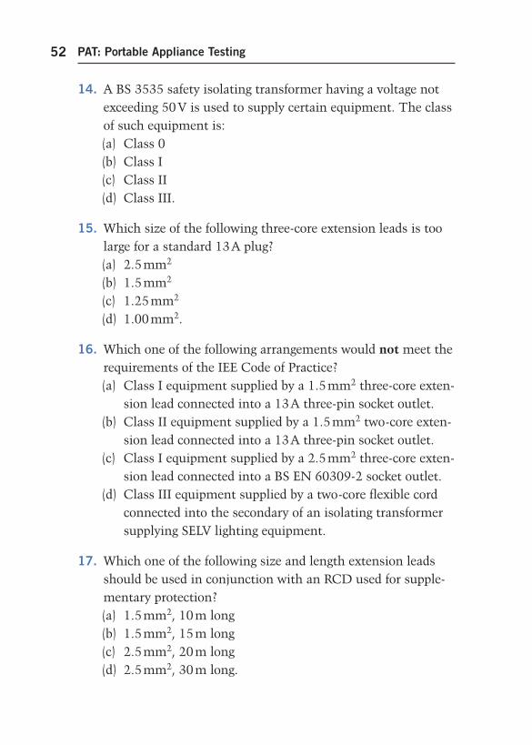
14. A BS 3535 safety isolating transformer having a voltage not exceeding 50 V is used to supply certain equipment. The class of such equipment is: (a) Class 0 (b) Class I (c) Class II (d) Class III.
15. Which size of the following three-core extension leads is too large for a standard 13 A plug? (a) 2.5 mm 2 (b) 1.5 mm 2 (c) 1.25 mm 2 (d) 1.00 mm 2 .
16. Which one of the following arrangements would not meet the requirements of the IEE Code of Practice? (a) Class I equipment supplied by a 1.5 mm 2 three-core exten-
sion lead connected into a 13 A three-pin socket outlet. (b) Class II equipment supplied by a 1.5 mm 2 two-core exten-
sion lead connected into a 13 A three-pin socket outlet. (c) Class I equipment supplied by a 2.5 mm 2 three-core exten-
sion lead connected into a BS EN 60309-2 socket outlet. (d) Class III equipment supplied by a two-core flexible cord
connected into the secondary of an isolating transformer supplying SELV lighting equipment.
17. Which one of the following size and length extension leads should be used in conjunction with an RCD used for supple-mentary protection? (a) 1.5 mm 2 , 10 m long (b) 1.5 mm 2 , 15 m long (c) 2.5 mm 2 , 20 m long (d) 2.5 mm 2 , 30 m long.
app-3-h8736.indd 52app-3-h8736.indd 52 4/22/2008 10:52:24 AM4/22/2008 10:52:24 AM
Appendix 3: Sample 2377 Questions 53
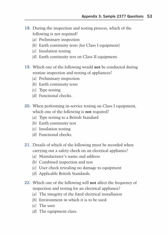
18. During the inspection and testing process, which of the following is not required? (a) Preliminary inspection (b) Earth continuity tests (for Class I equipment) (c) Insulation testing (d) Earth continuity test on Class II equipment.
19. Which one of the following would not be conducted during routine inspection and testing of appliances? (a) Preliminary inspection (b) Earth continuity tests (c) Type testing (d) Functional checks.
20. When performing in-service testing on Class I equipment, which one of the following is not required? (a) Type testing to a British Standard (b) Earth continuity test (c) Insulation testing (d) Functional checks.
21. Details of which of the following must be recorded when carrying out a safety check on an electrical appliance? (a) Manufacturer’s name and address (b) Combined inspection and test (c) User check revealing no damage to equipment (d) Applicable British Standards.
22. Which one of the following will not affect the frequency of inspection and testing for an electrical appliance? (a) The integrity of the fixed electrical installation (b) Environment in which it is to be used (c) The user (d) The equipment class.
app-3-h8736.indd 53app-3-h8736.indd 53 4/22/2008 10:52:25 AM4/22/2008 10:52:25 AM
PAT: Portable Appliance Testing54
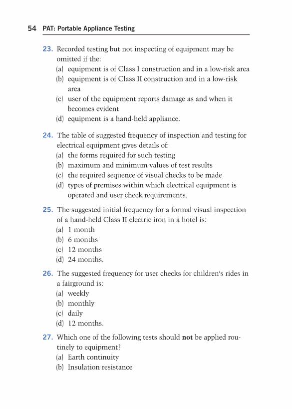
23. Recorded testing but not inspecting of equipment may be omitted if the: (a) equipment is of Class I construction and in a low-risk area (b) equipment is of Class II construction and in a low-risk
area (c) user of the equipment reports damage as and when it
becomes evident (d) equipment is a hand-held appliance.
24. The table of suggested frequency of inspection and testing for electrical equipment gives details of: (a) the forms required for such testing (b) maximum and minimum values of test results (c) the required sequence of visual checks to be made (d) types of premises within which electrical equipment is
operated and user check requirements.
25. The suggested initial frequency for a formal visual inspection of a hand-held Class II electric iron in a hotel is: (a) 1 month (b) 6 months (c) 12 months (d) 24 months.
26. The suggested frequency for user checks for children’s rides in a fairground is: (a) weekly (b) monthly (c) daily (d) 12 months.
27. Which one of the following tests should not be applied rou-tinely to equipment? (a) Earth continuity (b) Insulation resistance
app-3-h8736.indd 54app-3-h8736.indd 54 4/22/2008 10:52:25 AM4/22/2008 10:52:25 AM
Appendix 3: Sample 2377 Questions 55
(c) Polarity (d) Dielectric strength.
28. The first electrical test to be applied to Class I equipment is: (a) insulation resistance (b) earth continuity (c) dielectric strength (d) polarity.
29. When information regarding test procedures is unavailable from the manufacturer or supplier of IT equipment, which one of the following electrical tests should not be undertaken? (a) Earth continuity (b) Polarity (c) Functional (d) Insulation.
30. The purpose of an equipment register is to ensure: (a) compliance with the Electricity at Work Regulations (b) that maintenance procedures are recorded (c) the frequency of inspection and test is reviewed (d) inspection and testing is performed.
31. Identification of all electrical equipment within a duty holder’s control is required in order to produce: (a) ‘ pass ’ safety check equipment label (b) faulty equipment register (c) equipment register (d) repair register.
32. Which one of the following items of information is not required on an inspection and test label? (a) An indication of whether the equipment has passed or
failed the safety tests (b) Details of previous test results
app-3-h8736.indd 55app-3-h8736.indd 55 4/22/2008 10:52:25 AM4/22/2008 10:52:25 AM
PAT: Portable Appliance Testing56
(c) Date at time of testing (d) Appliance or equipment number.
33. All electrical equipment should be marked with a unique serial number to aid: (a) disconnection (b) identification (c) risk assessment (d) interpretation of test results.
34. Information provided for equipment which requires routine inspection and/or testing should consist of: (a) an indelible bar-code system (b) an identification code to enable the equipment to be
uniquely identifiable (c) operating instructions regarding the test equipment (d) an indication of the results which may be expected during
inspections and/or tests.
35. Which one of the following is not required to be tested within the scope of the IEE Code of Practice? (a) Fixed equipment (b) Fixed installations (c) Electrical tools (d) Portable appliances.
36. The Memorandum of Guidance on the Electricity at Work Regulations 1989 advises that equipment records: (a) should be kept throughout the working life of the
equipment (b) should only be kept where the equipment is used in high-
risk areas (c) are not required where the equipment is used in low-risk
areas (d) are not required if the equipment is fed from a 110 V
safety supply.
app-3-h8736.indd 56app-3-h8736.indd 56 4/22/2008 10:52:25 AM4/22/2008 10:52:25 AM
Appendix 3: Sample 2377 Questions 57
37. Records of all maintenance activities relating to electrical appliances must be kept, including details of the: (a) initial cost (b) procurement of equipment (c) estimated replacement date (d) estimated replacement cost.
38. The person responsible for carrying out an inspection and test on an appliance should have made available to them: (a) a list of all the users of equipment (b) a copy of the Electricity at Work Regulations (c) a copy of the Health and Safety at Work Act (d) previous inspection and test results.
39. Which voltage must be used when carrying out an insulation resistance test on a Class I toaster? (a) 3750 V AC (b) 500 V DC (c) 1000 V DC (d) 500 V AC .
40. An insulation resistance tester should be capable of: (a) delivering a minimum voltage of 1000 V DC to the load (b) testing the continuity of an earthing circuit (c) delivering a maximum voltage of 25 A through the load (d) maintaining the test voltage required across the load.
41. Where a user check reveals damage to equipment, it must be reported to: (a) the equipment manufacturer (b) the Health and Safety Inspectorate (c) a responsible person (d) a manager of an inspection and test organization.
app-3-h8736.indd 57app-3-h8736.indd 57 4/22/2008 10:52:25 AM4/22/2008 10:52:25 AM
PAT: Portable Appliance Testing58
42. The manager of an inspection and test organization should be able to: (a) repair faulty electrical equipment (b) instruct untrained persons in the use of portable appliance
testers (c) know their legal responsibilities under the Electricity at
Work Regulations (d) demonstrate competence in the use of appliance
testers.
43. Which one of the following is outside the scope of the IEE Code of Practice for Inspection and Testing of In-Service Electrical Equipment? (a) Those who inspect and test (b) The user of electrical appliances (c) Managers of the inspection and test organization (d) The hirer of electrical portable appliances and
equipment.
44. Earth continuity testing may in certain circumstances be carried out by means of: (a) a low-resistance ohmmeter (b) an insulation resistance tester (c) a bell set and battery (d) an instrument complying with BS EN 60309.
45. Test leads and probes used to measure voltages over 50 V AC and 100 V DC should comply with: (a) BS 7671 (b) Health and Safety Executive Guidance Note GS 38 (c) BS 5490 Specification for Classification of Protection (d) IEC Publication 479.
app-3-h8736.indd 58app-3-h8736.indd 58 4/22/2008 10:52:25 AM4/22/2008 10:52:25 AM
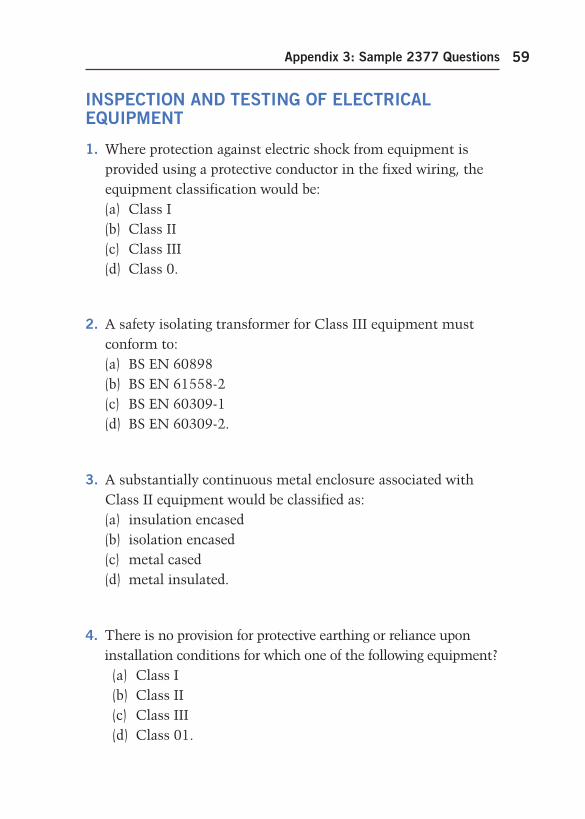
Appendix 3: Sample 2377 Questions 59
INSPECTION AND TESTING OF ELECTRICAL EQUIPMENT
1. Where protection against electric shock from equipment is provided using a protective conductor in the fixed wiring, the equipment classification would be: (a) Class I (b) Class II (c) Class III (d) Class 0.
2. A safety isolating transformer for Class III equipment must conform to: (a) BS EN 60898 (b) BS EN 61558-2 (c) BS EN 60309-1 (d) BS EN 60309-2.
3. A substantially continuous metal enclosure associated with Class II equipment would be classified as: (a) insulation encased (b) isolation encased (c) metal cased (d) metal insulated.
4. There is no provision for protective earthing or reliance upon installation conditions for which one of the following equipment? (a) Class I (b) Class II (c) Class III (d) Class 01.
app-3-h8736.indd 59app-3-h8736.indd 59 4/22/2008 10:52:25 AM4/22/2008 10:52:25 AM
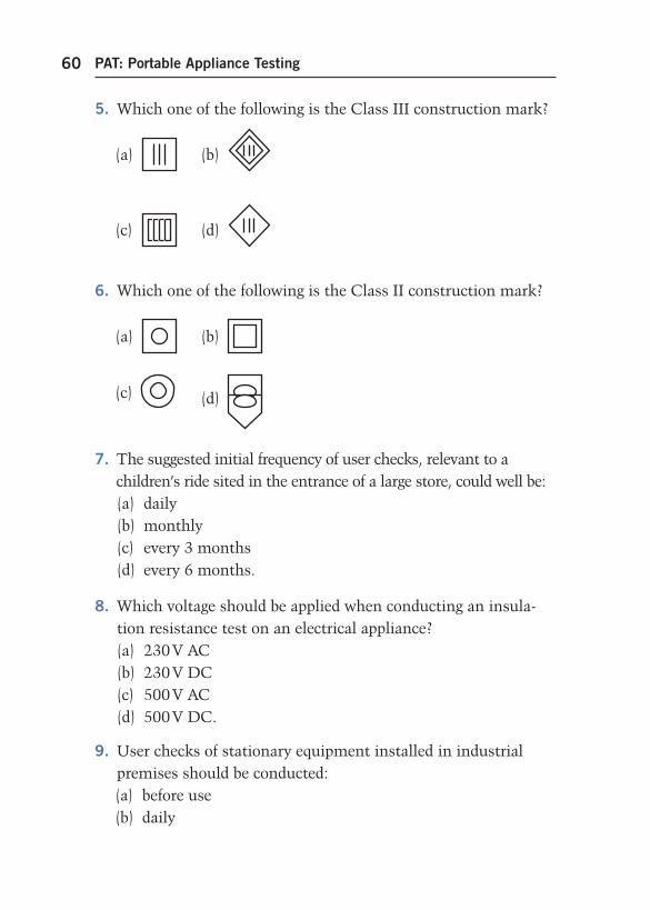
PAT: Portable Appliance Testing60
5. Which one of the following is the Class III construction mark?
(a)
(b)
(c)
(d)
6. Which one of the following is the Class II construction mark?
(a)
(b)
(c)
(d)
7. The suggested initial frequency of user checks, relevant to a children’s ride sited in the entrance of a large store, could well be: (a) daily (b) monthly (c) every 3 months (d) every 6 months.
8. Which voltage should be applied when conducting an insula-tion resistance test on an electrical appliance? (a) 230 V AC (b) 230 V DC (c) 500 V AC (d) 500 V DC.
9. User checks of stationary equipment installed in industrial premises should be conducted: (a) before use (b) daily
app-3-h8736.indd 60app-3-h8736.indd 60 4/22/2008 10:52:25 AM4/22/2008 10:52:25 AM
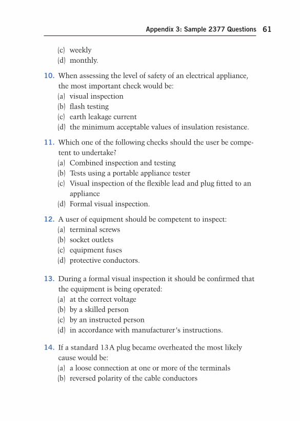
Appendix 3: Sample 2377 Questions 61
(c) weekly (d) monthly.
10. When assessing the level of safety of an electrical appliance, the most important check would be: (a) visual inspection (b) flash testing (c) earth leakage current (d) the minimum acceptable values of insulation resistance.
11. Which one of the following checks should the user be compe-tent to undertake? (a) Combined inspection and testing (b) Tests using a portable appliance tester (c) Visual inspection of the flexible lead and plug fitted to an
appliance (d) Formal visual inspection.
12. A user of equipment should be competent to inspect: (a) terminal screws (b) socket outlets (c) equipment fuses (d) protective conductors.
13. During a formal visual inspection it should be confirmed that the equipment is being operated: (a) at the correct voltage (b) by a skilled person (c) by an instructed person (d) in accordance with manufacturer’s instructions.
14. If a standard 13 A plug became overheated the most likely cause would be: (a) a loose connection at one or more of the terminals (b) reversed polarity of the cable conductors
app-3-h8736.indd 61app-3-h8736.indd 61 4/22/2008 10:52:27 AM4/22/2008 10:52:27 AM
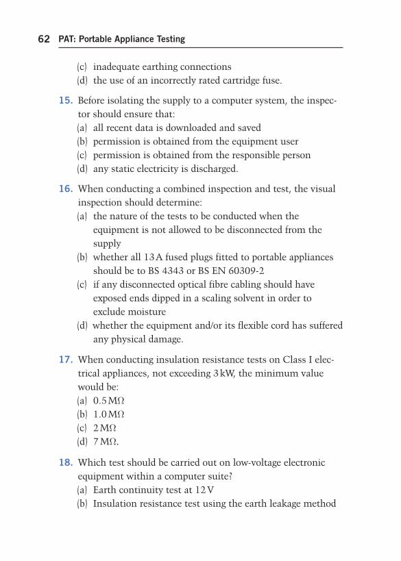
PAT: Portable Appliance Testing62
(c) inadequate earthing connections (d) the use of an incorrectly rated cartridge fuse.
15. Before isolating the supply to a computer system, the inspec-tor should ensure that: (a) all recent data is downloaded and saved (b) permission is obtained from the equipment user (c) permission is obtained from the responsible person (d) any static electricity is discharged.
16. When conducting a combined inspection and test, the visual inspection should determine: (a) the nature of the tests to be conducted when the
equipment is not allowed to be disconnected from the supply
(b) whether all 13 A fused plugs fitted to portable appliances should be to BS 4343 or BS EN 60309-2
(c) if any disconnected optical fibre cabling should have exposed ends dipped in a scaling solvent in order to exclude moisture
(d) whether the equipment and/or its flexible cord has suffered any physical damage.
17. When conducting insulation resistance tests on Class I elec-trical appliances, not exceeding 3 kW, the minimum value would be: (a) 0.5 M Ω (b) 1.0 M Ω (c) 2 M Ω (d) 7 M Ω .
18. Which test should be carried out on low-voltage electronic equipment within a computer suite? (a) Earth continuity test at 12 V (b) Insulation resistance test using the earth leakage method
app-3-h8736.indd 62app-3-h8736.indd 62 4/22/2008 10:52:27 AM4/22/2008 10:52:27 AM
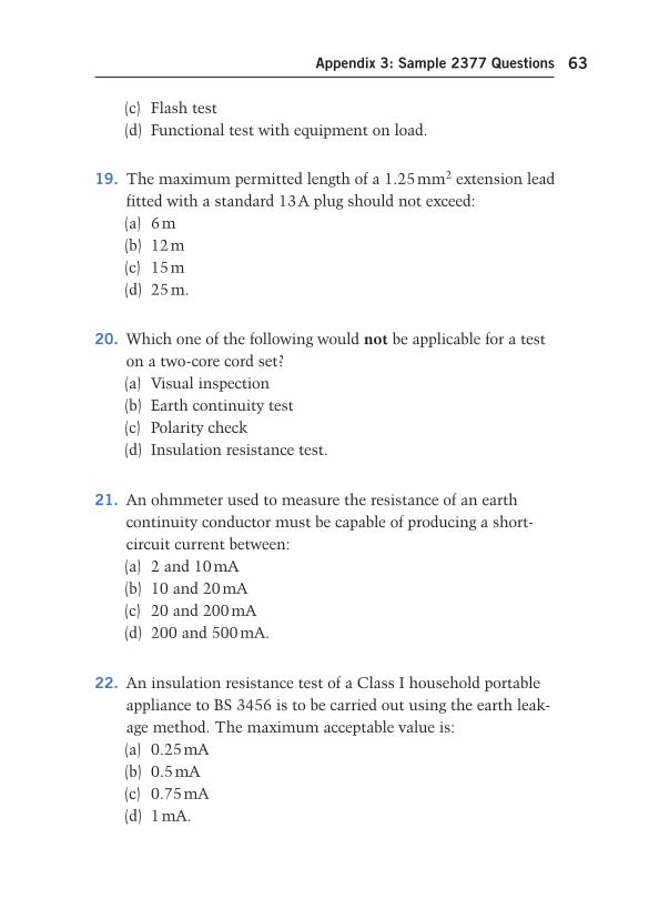
Appendix 3: Sample 2377 Questions 63
(c) Flash test (d) Functional test with equipment on load.
19. The maximum permitted length of a 1.25 mm 2 extension lead fitted with a standard 13 A plug should not exceed: (a) 6 m (b) 12 m (c) 15 m (d) 25 m.
20. Which one of the following would not be applicable for a test on a two-core cord set? (a) Visual inspection (b) Earth continuity test (c) Polarity check (d) Insulation resistance test.
21. An ohmmeter used to measure the resistance of an earth continuity conductor must be capable of producing a short-circuit current between: (a) 2 and 10 mA (b) 10 and 20 mA (c) 20 and 200 mA (d) 200 and 500 mA.
22. An insulation resistance test of a Class I household portable appliance to BS 3456 is to be carried out using the earth leak-age method. The maximum acceptable value is: (a) 0.25 mA (b) 0.5 mA (c) 0.75 mA (d) 1 mA.
app-3-h8736.indd 63app-3-h8736.indd 63 4/22/2008 10:52:27 AM4/22/2008 10:52:27 AM
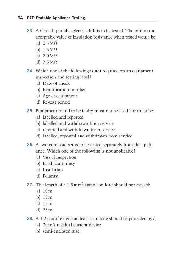
PAT: Portable Appliance Testing64
23. A Class II portable electric drill is to be tested. The minimum acceptable value of insulation resistance when tested would be: (a) 0.5 M Ω (b) 1.5 M Ω (c) 2.0 M Ω (d) 7.5 M Ω .
24. Which one of the following is not required on an equipment inspection and testing label? (a) Date of check (b) Identification number (c) Age of equipment (d) Re-test period.
25. Equipment found to be faulty must not be used but must be: (a) labelled and reported (b) labelled and withdrawn from service (c) reported and withdrawn from service (d) labelled, reported and withdrawn from service.
26. A two-core cord set is to be tested separately from the appli-ance. Which one of the following is not applicable? (a) Visual inspection (b) Earth continuity (c) Insulation (d) Polarity.
27. The length of a 1.5 mm 2 extension lead should not exceed: (a) 10 m (b) 12 m (c) 15 m (d) 25 m.
28. A 1.25 mm 2 extension lead 15 m long should be protected by a: (a) 30 mA residual current device (b) semi-enclosed fuse
app-3-h8736.indd 64app-3-h8736.indd 64 4/22/2008 10:52:27 AM4/22/2008 10:52:27 AM
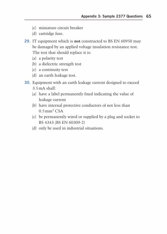
Appendix 3: Sample 2377 Questions 65
(c) miniature circuit breaker (d) cartridge fuse.
29. IT equipment which is not constructed to BS EN 60950 may be damaged by an applied voltage insulation resistance test. The test that should replace it is: (a) a polarity test (b) a dielectric strength test (c) a continuity test (d) an earth leakage test.
30. Equipment with an earth leakage current designed to exceed 3.5 mA shall: (a) have a label permanently fixed indicating the value of
leakage current (b) have internal protective conductors of not less than
0.5 mm 2 CSA (c) be permanently wired or supplied by a plug and socket to
BS 4343 (BS EN 60309-2) (d) only be used in industrial situations.
app-3-h8736.indd 65app-3-h8736.indd 65 4/22/2008 10:52:27 AM4/22/2008 10:52:27 AM

app-3-h8736.indd 66app-3-h8736.indd 66 4/22/2008 10:52:27 AM4/22/2008 10:52:27 AM
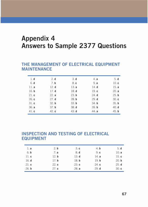
67
Appendix 4 Answers to Sample 2377 Questions
THE MANAGEMENT OF ELECTRICAL EQUIPMENT MAINTENANCE
1. d 2. d 3. d 4. a 5. d
6. d 7. b 8. c 9. a 10. c
11. a 12. d 13. a 14. d 15. a
16. b 17. d 18. d 19. c 20. a
21. c 22. a 23. b 24. d 25. b
26. c 27. d 28. b 29. d 30. c
31. c 32. b 33. b 34. b 35. b
36. a 37. b 38. d 39. b 40. d
41. c 42. c 43. d 44. a 45. b
INSPECTION AND TESTING OF ELECTRICAL EQUIPMENT
1. a 2. b 3. c 4. b 5. d
6. b 7. a 8. d 9. c 10. a
11. c 12. b 13. d 14. a 15. c
16. d 17. b 18. b 19. b 20. b
21. c 22. c 23. c 24. c 25. d
26. b 27. c 28. a 29. d 30. c
app-4-h8736.indd 67app-4-h8736.indd 67 4/22/2008 10:54:13 AM4/22/2008 10:54:13 AM

app-4-h8736.indd 68app-4-h8736.indd 68 4/22/2008 10:54:13 AM4/22/2008 10:54:13 AM
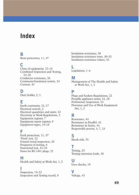
69
Index
B Basic protection , 11 , 37
C Class of equipment , 12–16 Combined Inspection and Testing ,
23–26 Conductor resistance , 26 Continuity/Insulation testers , 24 Current , 43
D Duty holder , 2 , 5
E Earth continuity , 25 , 27 Electrical system , 2 Electrical quantities and units , 43 Electricity at Work Regulations, 2 Equipment register , 7 Equipment repair register , 9 Equipment types , 16–18
F Fault protection , 11 , 37 ‘Flash’ test , 32 Formal visual inspection , 20 Frequency of testing , 6 Functional test , 32–33 Fuses for BS 1361 plugs , 22
H Health and Safety at Work Act , 1 , 2
I Inspection , 19–22 Inspection and Testing record , 8
Insulation resistance , 30 Insulation resistance tests , 30–32 Insulation resistance values , 32
L Legislation , 1–4
M Management of The Health and Safety
at Work Act , 1 , 2
P Plugs and Sockets Regulations , 22 Portable appliance tester , 24 , 28 Preliminary Inspection , 23 Provision and Use of Work Equipment
Act , 1 , 2
R Resistance , 43 Resistance in Parallel , 45 Resistance in Series , 44 Responsible person , 5 , 7 , 23
S Shock risk , 35
T Testing , 23 Testing extension leads , 30
U User checks , 19
V Voltage , 43
index-h8736.indd 69index-h8736.indd 69 4/22/2008 10:56:07 AM4/22/2008 10:56:07 AM

index-h8736.indd 70index-h8736.indd 70 4/22/2008 10:56:07 AM4/22/2008 10:56:07 AM


![[Brian Scaddan] PAT Portable Appliance Testing, S(Bookos.org)](https://static.fdocuments.us/doc/165x107/545d9e67b1af9f370a8b4895/brian-scaddan-pat-portable-appliance-testing-sbookosorg.jpg)


![PAT - Portable Appliance Testing[1]](https://static.fdocuments.us/doc/165x107/577cbc761a28aba7118da66b/pat-portable-appliance-testing1.jpg)

