PORTABLE ANCHOR SYSTEMS: TERRADAPTORTM MODULE 2 · Portable Anchor Systems: TerrAdaptor™ Module 2...
45
When you work in a vertical world you need Vertical Rescue Solutions www.verticalrescuesolutions.com PORTABLE ANCHOR SYSTEMS: STUDENT MANUAL Version 1.0 TERRADAPTOR TM MODULE 2
Transcript of PORTABLE ANCHOR SYSTEMS: TERRADAPTORTM MODULE 2 · Portable Anchor Systems: TerrAdaptor™ Module 2...

When you work in a vertical world you need
Vertical Rescue Solutions
www.verticalrescuesolutions.com
PORTABLE ANCHOR SYSTEMS:
STUDENT MANUAL Version 1.0TERRADAPTORTM MODULE 2

Contents
2
Portable Anchor Systems: TerrAdaptor™ Module 2 v 1.0 - 2009
Course Description - - - - - - - - - - - - - - - - - - - - - - - - - - - - - - - - - - - - - - - - - - - - - 3
Prerequisites - - - - - - - - - - - - - - - - - - - - - - - - - - - - - - - - - - - - - - - - - - - - - - - - 3
Learning Objectives - - - - - - - - - - - - - - - - - - - - - - - - - - - - - - - - - - - - - - - - - - - - 3
Order of Instruction - - - - - - - - - - - - - - - - - - - - - - - - - - - - - - - - - - - - - - - - - - - - 4
Lesson 1: Introduction and Overview of Course - - - - - - - - - - - - - - - - - - - - - - - - - - 5
Lesson 2: Safety Issues - - - - - - - - - - - - - - - - - - - - - - - - - - - - - - - - - - - - - - - - - - 7
Lesson 3: Whiteboard Analysis of Resultants - - - - - - - - - - - - - - - - - - - - - - - - - - - - 9
Lesson 4: Friction Issues - - - - - - - - - - - - - - - - - - - - - - - - - - - - - - - - - - - - - - - - - 17
Lesson 5: Resultant Forces Applied to Tripods and Quad-pods - - - - - - - - - - - - - - - 21
Lesson 6: Swiss Anchors (AKA Anchors Kept in a Neutral State) - - - - - - - - - - - - - - - 23
Lesson 7: Bi-pods: A-Frames - - - - - - - - - - - - - - - - - - - - - - - - - - - - - - - - - - - - - 29
Lesson 8: Bi-pods: Angled A-Frames - - - - - - - - - - - - - - - - - - - - - - - - - - - - - - - - 31
Lesson 9: Mono-pods/Gin Poles - - - - - - - - - - - - - - - - - - - - - - - - - - - - - - - - - - - 35
Appendix
TerrAdaptor™ Module 2 - Written Exam (25 points total)
Release and Assumption of Risk Form

3
Portable Anchor Systems: TerrAdaptor™ Module 2 v 1.0 - 2009
© 2008-2009 Pigeon Mountain Industries VRS by PMITM and Pigeon Mountain Industries do not guarantee the accuracy or completeness of any information in, or provided
in connection with, this manual. VRS by PMITM and Pigeon Mountain Industries are not responsible for any errors or omissions, or for the results obtained from the use of such information. VRS by PMITM and Pigeon Mountain Industries do not guarantee the safety of those participating in training using this manual.
Course DescriptionThis is a two-day rope technician intermediate skills course that instructs participants in the
use of portable anchor systems using the TerrAdaptor™ and supports sound and reliable
manipulative mono-pod and bi-pod skills congruent with the requirements of NFPA 1670
and 1006 Technician Level training. Intermediate force multiplier theory that is applicable
to portable anchors is a key component of Module 2.
PrerequisitesSuccessful completion of Portable Anchor Systems: Theoretical and Practical Application of
the TerrAdaptor™, Module 1 of this series.
Learning ObjectivesUpon successful completion of Module 2, all participants will be able to safely and
efficiently accomplish the following tasks and objectives:
1. Construct and operate individual and system belays congruent to the use of mono-pods and bi-pods
2. Construct and operate a mainline system congruent to the use of mono-pods and bi-pods
3. Understand basic principles of force multipliers as they apply to whiteboard analysis of critical angles, and the relation between compression and tension as they apply to portable anchor systems, with a focus on mono-pods and bi-pods
4. Rig and manage mono-pods and bi-pods congruent to the requirements of this course
5. Rig the TerrAdaptor™ as a mono-pod and bi-pod congruent to the requirements of the TerrAdatpor™ User’s Manual and to the satisfaction of the lead instructor
6. Complete and pass the TerrAdaptor™ Module 2 written test

4
Portable Anchor Systems: TerrAdaptor™ Module 2 v 1.0 - 2009
Order of Instruction
1. Introduction and Overview of Course• The purpose of VRS™• The instructor’s expectations for the course as well as your classmate’s and your
own• The flow of the course
2. Safety Issues• Release and Assumption of Risk Form• Two points of contact for anyone within six-feet of the edge (for flat surfaces, this
may be more depending on the terrain)— No one is allowed to approach the edge without full approval and
inspection of the instructor— Anyone can call STOP at any time if they have a safety question or issue
about what is taking place• Required Personal Gear and PPE
— Class 3 Harness (preferred)— Helmet (rescue type with three-point chin strap)— Gloves (leather rappel type)— Appropriate Footwear (hiking boots or duty boots, no tennis or jogging
shoes)— Appropriate attire to meet climate requirements— Personal snacks and water
3. Whiteboard Analysis of Resultants• Vector Components and Angles• Pulley Resultants• Parallelogram/Resultant Analysis• Vector Formulas
4. Friction Issues• Friction Law• Coefficient of Friction• Dynamic Friction
5. System Safety Factors• SSSF (Static System Safety Factor)• DSSF (Dynamic System Safety Factor)
6. Back-ties and the Relationship Between Compression and Tension• Back-ties• Compression• Tension
7. Bi-pods: A-Frames
8. Bi-pods: Angled A-Frames
9. Mono-pods/Gin Poles

5
Portable Anchor Systems: TerrAdaptor™ Module 2 v 1.0 - 2009
6
Portable Anchor Systems: TerrAdaptor™ Module 2 v 1.0 - 2009
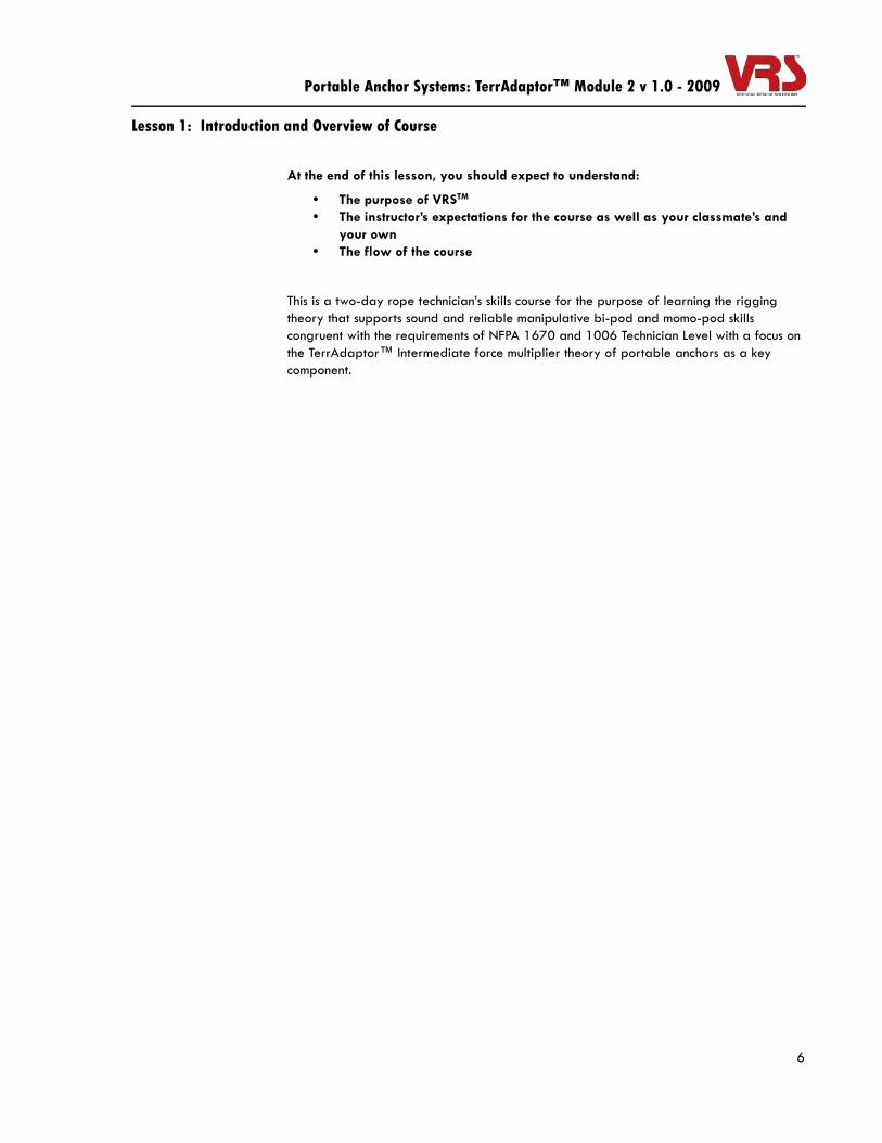
Lesson 1: Introduction and Overview of Course
At the end of this lesson, you should expect to understand:
• The purpose of VRSTM • The instructor’s expectations for the course as well as your classmate’s and
your own• The flow of the course
This is a two-day rope technician’s skills course for the purpose of learning the rigging theory that supports sound and reliable manipulative bi-pod and momo-pod skills congruent with the requirements of NFPA 1670 and 1006 Technician Level with a focus on the TerrAdaptor™ Intermediate force multiplier theory of portable anchors as a key component.

7
Portable Anchor Systems: TerrAdaptor™ Module 2 v 1.0 - 2009

8
Portable Anchor Systems: TerrAdaptor™ Module 2 v 1.0 - 2009
Lesson 2: Safety Issues
By the end of this lesson, you should expect to understand:
• The importance of the overall safety briefing• Edge safety protocols• Required personal protective gear (PPE)
Inattention to safety during a rescue and/or training becomes and emergency in its own right. It is the responsibility of each participant in this class to be on guard against non-safe situations. Catastrophic failures can always be traced back to the accumulative effect of several “lesser” mess-ups, over-sights, or in many cases, a simple lack of knowledge and training. Safety is a state of mind.
This course will involve work that is in close proximity to dangerous edges; anyone within six-feet of an unprotected edge shall be connected to an appropriate fall arrest system and subject to the direction and interpretation of the lead instructor. Dependant on the conditions of the terrain, a great distance from the edge may require fall arrest.
ANYONE MAY CALL FOR A “STOP” IF A SAFETY ISSUE OR QUESTION OF SAFETY ARISES!
1. Review Safety Issues, Including:
• Release and Assumption of Risk Form
• Two points of contact for anyone within six-feet of the edge (for flat surfaces, this may be more depending on the terrain)
• No one is allowed to approach the edge without full approval and inspection of the instructor
• Anyone can call STOP at any time if they have safety questions or issues about what is taking place

9
Lesson 2: Safety Issues (Cont.)
Portable Anchor Systems: TerrAdaptor™ Module 2 v 1.0 - 2009
2. Required Personal Gear and PPE:
• Class 3 Harness (preferred)
• Helmet (rescue type with three-point chin strap)
• Gloves (leather rappel type)
• Appropriate Footwear (hiking boots or duty boots, no tennis or jogging shoes)
• Appropriate attire to meet climate requirements
• Personal snacks and water

10
Portable Anchor Systems: TerrAdaptor™ Module 2 v 1.0 - 2009
Lesson 3: Whiteboard Analysis of Resultants
By the end of this lesson, you should expect to understand:
• How to calculate the resultant created by force factors on a pulley in a portable anchor system
• Why it is important to memorize the percentage a given load exerts on both the main pulley and directional pulley anchors based on vector formulas
To understand rigging is to understand at least some aspects of trigonometry and vector physics. The knowledge of angles, components and resultants is synonymous to quality of rope rigging. To study vectors is to study the physical qualities of force that has both direction and magnitude.
A force vector may be graphed or represented as a simple arrow, also more commonly referred to in math as a component. This component will always indicate the direction of the force.
In addition to seeing the direction of force vectors, comparing the length of different vector components will reveal the magnitude relative to each other.
The longer component will always have a greater magnitude. In the example above, the component on the right has approximately twice the magnitude as the one on the left.
Two components that connect for an angle. The resultant is the net force of the angle these two components create.
11
Lesson 3: Whiteboard Analysis of Resultants (Cont.)
Portable Anchor Systems: TerrAdaptor™ Module 2 v 1.0 - 2009
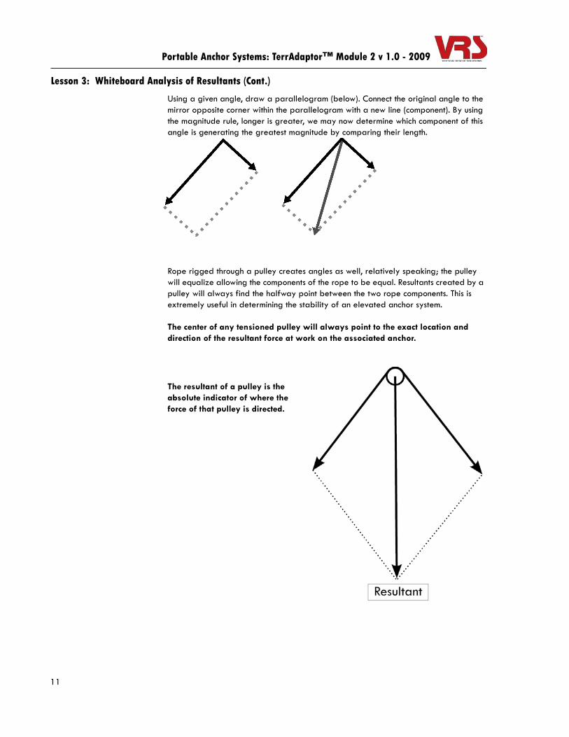
Using a given angle, draw a parallelogram (below). Connect the original angle to the mirror opposite corner within the parallelogram with a new line (component). By using the magnitude rule, longer is greater, we may now determine which component of this angle is generating the greatest magnitude by comparing their length.
Rope rigged through a pulley creates angles as well, relatively speaking; the pulley will equalize allowing the components of the rope to be equal. Resultants created by a pulley will always find the halfway point between the two rope components. This is extremely useful in determining the stability of an elevated anchor system.
The center of any tensioned pulley will always point to the exact location and direction of the resultant force at work on the associated anchor.
The resultant of a pulley is the absolute indicator of where the force of that pulley is directed.

12
Lesson 3: Whiteboard Analysis of Resultants (Cont.)
Portable Anchor Systems: TerrAdaptor™ Module 2 v 1.0 - 2009
One of the most misunderstood issues of rope rigging is the analysis of the angle of a multipoint anchor system versus the same angle of a directional pulley. Most rope rescue personnel have committed to rote memory that with a 90o angle, each anchor of a 2 by 1 multipoint anchor system will receive 71% of the load, or with a 150o angle each anchor will receive 200% of the load. Given the same angles of rope going in and coming out of a directional pulley, when asked to give the force on the directional pulley anchor, many rescuers will erroneously give the same answer.
Study the two right angle rope systems below; both have two anchors and both support a 100kg load. What percentage of the load is each anchor receiving?
If you said A1 and A2 receive 71kg, A3 receives 100kg, and A4 receives 141kg you would be correct.
Resultant
Component 2
Component 1

13
Lesson 3: Whiteboard Analysis of Resultants (Cont.)
Portable Anchor Systems: TerrAdaptor™ Module 2 v 1.0 - 2009
Look at these right angles again and apply the parallelogram/resultant analysis:
The 100kg load is our known value, whatever component the load is connected to represents 100; the remaining two components may now be assigned a value simply by comparing their length. C3 = 100, therefore C1 and C2 are 71% of C3 - C5 = 100, therefore C4 = 100% of C5 and C6 = 141% of C5.
Although using parallelograms as mentioned above to determine the resultant of any given angle is a good rule of thumb method, ultimately, for field application we must commit to rote memory the recognition of angles as they apply to either, 1) multipoint systems, or 2) directional pulley anchors.

14
Lesson 3: Whiteboard Analysis of Resultants (Cont.)
Portable Anchor Systems: TerrAdaptor™ Module 2 v 1.0 - 2009
Vector Formula for Directional Pulley Anchors
High Directional Vector Force:Degree of Angle % of Weight of Load At
High Directional0 . . . . . . . . . . . . . . . . . . . . . . . . . 200%5 . . . . . . . . . . . . . . . . . . . . . . . . . 199.9%10 . . . . . . . . . . . . . . . . . . . . . . . . 199%15 . . . . . . . . . . . . . . . . . . . . . . . . 198%20 . . . . . . . . . . . . . . . . . . . . . . . . 197%25 . . . . . . . . . . . . . . . . . . . . . . . . 195%30 . . . . . . . . . . . . . . . . . . . . . . . . 193%35 . . . . . . . . . . . . . . . . . . . . . . . . 191%40 . . . . . . . . . . . . . . . . . . . . . . . . 188%45 . . . . . . . . . . . . . . . . . . . . . . . . 185%50 . . . . . . . . . . . . . . . . . . . . . . . . 181%60 . . . . . . . . . . . . . . . . . . . . . . . . 173%65 . . . . . . . . . . . . . . . . . . . . . . . . 169%70 . . . . . . . . . . . . . . . . . . . . . . . . 164%75 . . . . . . . . . . . . . . . . . . . . . . . . 159%80 . . . . . . . . . . . . . . . . . . . . . . . . 153%85 . . . . . . . . . . . . . . . . . . . . . . . . 147%90 . . . . . . . . . . . . . . . . . . . . . . . . 141%95 . . . . . . . . . . . . . . . . . . . . . . . . 135%100 . . . . . . . . . . . . . . . . . . . . . . . 129%105 . . . . . . . . . . . . . . . . . . . . . . . 122%110 . . . . . . . . . . . . . . . . . . . . . . . 115%115 . . . . . . . . . . . . . . . . . . . . . . . 107%120 . . . . . . . . . . . . . . . . . . . . . . . 100%125 . . . . . . . . . . . . . . . . . . . . . . . 92%130 . . . . . . . . . . . . . . . . . . . . . . . 85%135 . . . . . . . . . . . . . . . . . . . . . . . 77%140 . . . . . . . . . . . . . . . . . . . . . . . 68%145 . . . . . . . . . . . . . . . . . . . . . . . 60%150 . . . . . . . . . . . . . . . . . . . . . . . 52%155 . . . . . . . . . . . . . . . . . . . . . . . 43%160 . . . . . . . . . . . . . . . . . . . . . . . 35%165 . . . . . . . . . . . . . . . . . . . . . . . 26%
15
Lesson 3: Whiteboard Analysis of Resultants (Cont.)
Portable Anchor Systems: TerrAdaptor™ Module 2 v 1.0 - 2009
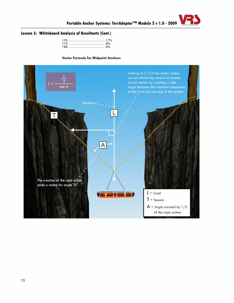
170. . . . . . . . . . . . . . . . . . . . . . . . 17%175. . . . . . . . . . . . . . . . . . . . . . . . 8%180. . . . . . . . . . . . . . . . . . . . . . . . 0%
Vector Formula for Midpoint Anchors

16
Lesson 3: Whiteboard Analysis of Resultants (Cont.)
Portable Anchor Systems: TerrAdaptor™ Module 2 v 1.0 - 2009

17
Portable Anchor Systems: TerrAdaptor™ Module 2 v 1.0 - 2009

18
Portable Anchor Systems: TerrAdaptor™ Module 2 v 1.0 - 2009
Lesson 4: Friction Issues
By the end of this lesson, you should expect to understand:
• How the coefficient of friction affects both the Dynamic System Safety Factor (DSSF) and the Static System Safety Factor (SSSF)
• How to roughly calculate the added amount of load that edge friction generates when hauling
Rigging is the use of tension and compression to either move something or to keep something from moving. Whether we are moving or holding something, friction is always there, working for or against us. This section on friction is a basic treatment of friction coefficients with a specific focus on how it will multiply the weight of the actual load during a hauling.
It is common practice in rope rescue to use a friction device such as a brake rack for the addition of friction during a lowering. When the mainline comes in contact with the edge during a lowering it is as if an additional brake rack has been added. Aside from any rope wear and tear of continual edge contact, this edge friction is working in our favor.
Now let’s convert our lowering to a raising system. The same edge contact that was working in our favor on the way down is now playing tug-of-war with the haul team! A matter of fact, a good rule of thumb measurement is about 3 times the weight of the load is really what the haul team has to overcome when the rope is being pulled over a rock ledge. This is arguable the single most important reason for the use of an elevated anchor system (i.e. the TerrAdaptor™) over difficult edges.
At the beginning of this chapter, the DSSF was mentioned. Traditionally, the SSSF is calculated prior to the implementation of a rope rescue, analyzed and a judgement is made based on the system’s weakest link. It is then decided if the system is rigged within the parameters of the previously established safety margin. This safety margin is often a 10:1 safety margin.
The DSSF on the other hand, judges the rigging system during its operation and predicts the weakest link during the greatest moment of system stress. This moment of greatest stress will always be during the transitions between a static state to a state of hauling, or to put it into physical terms - the transition from static friction to dynamic friction (sliding fruition).

19
Lesson 4: Friction Issues (Cont.)
Portable Anchor Systems: TerrAdaptor™ Module 2 v 1.0 - 2009
Friction Law
Friction is a force of resistance between two objects that opposes any motion. Friction may be further defined as being either static friction (force that tends to counter motion of an object that is in a state of rest), and kinetic friction (force wanting to slow an object in motion).
Coefficient of Friction
The coefficient of friction ( ) between an object and the surface on which it is at rest can be defined as the ratio of applied force ( ) needed to move the object divided by the normal force between the object and the surface ( ).
In rigging, what is the ratio of the amount of force (stress on the rope system) needed to initiate the hauling process divided by the loaded mainline at rest on a given surface prior to the start of the haul? Obviously the higher the coefficient of friction the more stress is added to the haul system and the entire anchor system.
Dynamic Friction
After the initial spike of needed force to move the object from a state of rest the dynamic friction (sliding friction) is the force needed to sustain movement over the surface.
The only true way to establish the coefficient of friction of any given surface is through detailed analysis in a laboratory setting.
Although we have performed multiple informal slow pull tests of a 50 pound load over a sandstone edge and steel hand rails at 90o contact surface, we have found the best and simplest way to prove this point in the classroom is through the use of tabletop demonstrations by raising a five pound weight over brick or a metal pipe on the edge of the table. We usually use 6mm rope connected to a 50 pound rated dynamometer (fish scale).
μ
fn
μ fn---=

20
Lesson 4: Friction Issues (Cont.)
Portable Anchor Systems: TerrAdaptor™ Module 2 v 1.0 - 2009
Going down, the five pound weight will register around one and a half to two pounds on the scale. Coming up, the same five pound weight will register around 18 plus pounds on the scale. The results of these small scale classroom demonstrations are remarkably close to the test we performed with 50 pound loads over a sandstone edge; dynamic coefficient of friction about 0.35 or a magnification of the load by approximately three times during the hauling process.
Round steel hand rails proved little relief with an increase of the true load of about twice as much.
Key Points:
• Avoid excessive rope contact with any surface
• Use elevated anchor systems, especially when hauling is predicted
• Remember, the true load is the rescue package plus any added friction - even moderate rock contact can increase this as much as three times the load!

21
Portable Anchor Systems: TerrAdaptor™ Module 2 v 1.0 - 2009

22
Portable Anchor Systems: TerrAdaptor™ Module 2 v 1.0 - 2009
Lesson 5: System Safety Factors
By the end of this lesson, you should expect to understand:
• How to calculate both a Static System Safety Factor (SSSF) and a Dynamic System Safety Factor (SSSD) based on the weakest link in each system
.
SSSF (Static System Safety Factor)
The SSSF is the ratio of the overall rope system divided by the load during a static state (no movement). This is based on the weakest component and/or equipment link from the anchor to the load
Example:
The anchor is Bombproof rigged with a Wrap 3, Pull 2 webbing system . . MBS 8500 lbs
The connecting carabiner to the anchor is steel. . . . . . . . . . . . . . . . . . . . . . . MBS 9000 lbs
The rigging plate is . . . . . . . . . . . . . . . . . . . . . . . . . . . . . . . . . . . . . . . . . . . . MBS 8000 lbs
The brake rack is . . . . . . . . . . . . . . . . . . . . . . . . . . . . . . . . . . . . . . . . . . . . . . MBS 5000 lbs
The rope with 50% de-rating for knot is . . . . . . . . . . . . . . . . . . . . . . . . . . . . MBS 4500 lbs
The connecting carabiner to the load is steel . . . . . . . . . . . . . . . . . . . . . . . . MBS 9000 lbs
The weakest link is 4500 lbs
Divided by the load of approximately 450 lbs
Divided by the load of 450 lbs plus a coefficient of friction of 3 (90o angle of contact with a sandstone edge) giving an actual load of 1350 lbs (450 x 3).
SSSF = 10:1
DSSF (Dynamic System Safety Factor)
The DSSF is the ratio of the overall rope system divided by the load plus all other physical factors during the predicted greatest moment of system stress - typically during the start of the hauling process of a rescue requiring a raising system.
Example:
The anchor is Bombproof rigged with a Wrap 3, Pull 2 webbing system . . MBS 8500 lbs
The connecting carabiner to the anchor is steel. . . . . . . . . . . . . . . . . . . . . . . MBS 9000 lbs
The rigging plate is . . . . . . . . . . . . . . . . . . . . . . . . . . . . . . . . . . . . . . . . . . . . MBS 8000 lbs
The brake rack is . . . . . . . . . . . . . . . . . . . . . . . . . . . . . . . . . . . . . . . . . . . . . . MBS 5000 lbs
The rope with 50% de-rating for knot is . . . . . . . . . . . . . . . . . . . . . . . . . . . . MBS 4500 lbs
23
Lesson 5: System Safety Factors (Cont.)
Portable Anchor Systems: TerrAdaptor™ Module 2 v 1.0 - 2009
The connecting carabiner to the load is steel . . . . . . . . . . . . . . . . . . . . . . . . . MBS 9000 lbs
The weakest link is 4500 lbs
Divided by the load of 450 lbs plus a coefficient of friction of 3 (90o angle of contact with a sandstone edge) giving an actual load of 1350 lbs (450 x 3).
DSSF = 3.3:1

24
Portable Anchor Systems: TerrAdaptor™ Module 2 v 1.0 - 2009
Lesson 6: Back-ties and the Relationship Between Compression and Tension
By the end of this lesson, you should expect to understand:
• Why it is important to keep a portable high directional anchor in a Swiss, or neutral, state
• The complex relationship between compression force and tensile force when using back-ties on portable anchor systems
• How to calculate the amount of stress applied to a tensioned member in an elevated portable anchor system
Back-ties, and the Relationship Between Compression and Tension
Compression force is the opposite of tensile force. As with all forms of construction, rope rigging included, one cannot exist without the other. One of our best examples of the use of compression and tension in technical rescue can be found when we use a tripod as an elevated anchor point (high directional).
The tripod does not become stable until the tensile force of the hanging load is applied, thereby allowing the compression of the three legs to oppose the tensile force of the load. Both must take place in harmony for us to have a workable rigging system.
The goal for the rigging of all anchors should be to keep them in a Swiss, or neutral, state.
Although typical 12.5mm rescue rope is strong enough to support a system load, a single leg used as a back-tie may stretch too much to keep the marginal anchor in a neutral state. Three legs of rope are commonly used to mitigate the stretching of the rope within the back-tie system once it has been fully loaded.

25
Lesson 6: Back-ties and the Relationship Between Compression and Tension (Cont.)
Portable Anchor Systems: TerrAdaptor™ Module 2 v 1.0 - 2009
The anchor system, including the rigging of the back-tie anchor system, must be adequate enough to support the resultant force applied to the anchor with at least a DSSF of 7:1.
Tensile Force can be defined as a pulling or stretching force that is applied equally between two points acting in opposite directions. Reducing tension and compression to their simplest state, at least in our world rigging, we are talking about two possibilities: load pulling against an anchor and/or an anchor pulling against an anchor.
Back-Ties
Back-Tie Anchor
Ratchet Prusik On The Last Leg Of The 3:1cd
Marginal Anchor
Tie off the “cd” with two ½ hitches.
3:1cd MA, extending the full distance between to two anchors. (carabiners, no pulleys)
Anchor
Load
Equal force is applied to the rope in both directions.
Back-tie Anchor
Mainline Anchor
Equal force is applied to both anchors in both directions.

26
Lesson 6: Back-ties and the Relationship Between Compression and Tension (Cont.)
Portable Anchor Systems: TerrAdaptor™ Module 2 v 1.0 - 2009
Compression Force can be defined as two forces of equal magnitude pushing on both ends of a solid object.
Anchor failure may occur when tension exceeds compression. Either the rope will break or the compression member of the anchor system will skid, bend or break.
Manufacturer standards such as NFPA 1983 give an additional layer of protection for the user in guaranteeing the quality of modern rigging gear. Most seasoned rope rescue technicians don’t need a detailed mathematical foundation. Having said this, the higher the technician climbs up the ladder of his/her’s rigging career - assistant instructor, lead instructor, research and development - the more these issues of physics and math come to the surface.
Equal opposing force is applied to the bar from the ground.
System failure will usually occur when tension exceeds compression.
Force is applied to the top of the bar.
Note: The 9mm rope employed in the tensioned back-ties connected to the TerrAdaptor Lashing Ring; even though these back-tie ropes are only rated for “Light” use per NFPA 1983, they are well above a 20:1 safety margin in this 2 person rescue load application. This is based on accurate tension and compression analysis performed by informed rope rescue veterans.

27
Lesson 6: Back-ties and the Relationship Between Compression and Tension (Cont.)
Portable Anchor Systems: TerrAdaptor™ Module 2 v 1.0 - 2009
Look at the relationship between a vertical compression member and a tensioned member of an elevated anchor system, more specifically, what is the stress on the tension member and how does this effect the anchor and equipment selection? Keep in mind this is a single dimension analysis. With additional tension members back-tie/guys and/or additional compression members typical to “A” frames, the distribution of tensile and compressive stress would be based on the respective angles of each member hence becoming a two dimensional analysis.
We must first calculate the resultant force placed on the apex of the high directional by the components of the loaded mainline.
Secondly, we will calculate the leverage ratio of the compression member over the tension member.
Lastly, we will calculate the ratio of the resultant force over the leverage ratio.
Stress on a single tensioned member of an elevated anchor system =
C = the angle created by the resultant component of the high directional pulley or the vector force that is attached to the top of the compression member of the elevated anchor system.
T = the angle at the top of the high directional where the compression and tension members join.
M = the magnitude of the resultant component.
Example 1:M = 200kg
Angle “C” = 90o to the compression member (maximum leverage)
Angle “T” = 30o
M SinC⋅SinT
----------------------
28
Lesson 6: Back-ties and the Relationship Between Compression and Tension (Cont.)
Portable Anchor Systems: TerrAdaptor™ Module 2 v 1.0 - 2009
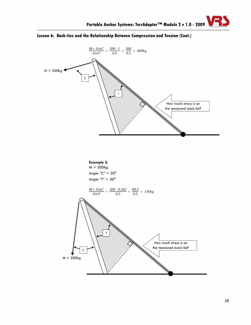
Example 2:M = 200kgAngle “C” = 20o
Angle “T” = 30o
M SinC×SinT
------------------------ 200 1⋅0.5
---------------- 2000.5--------- 400kg= = =
M SinC×SinT
------------------------ 200 0.342⋅0.5
--------------------------- 68.40.5---------- 136kg= = =

29
Lesson 6: Back-ties and the Relationship Between Compression and Tension (Cont.)
Portable Anchor Systems: TerrAdaptor™ Module 2 v 1.0 - 2009
Example 3:
The angle of the mainline going in and out of the high directional pulley is 40o.
M = 376kg (188% of the 200kg load)
Angle “C” = 5o (typical leverage from a high directional pulley resultant acting on a single compression member)
Angle “T” = 30o
M SinC×SinT
------------------------ 376 0.087×0.5
---------------------------- 32.70.5---------- 65kg= = =

30
Portable Anchor Systems: TerrAdaptor™ Module 2 v 1.0 - 2009
Lesson 7: Bi-pods: A-Frames
By the end of this lesson, you should expect to understand:
• When to use a bi-pod or A-Frame portable anchor system• The basic mechanics and physics involved in setting up bi-pods and A-Frames
A-Frames

31
Portable Anchor Systems: TerrAdaptor™ Module 2 v 1.0 - 2009

32
Portable Anchor Systems: TerrAdaptor™ Module 2 v 1.0 - 2009
Lesson 8: Bi-pods: Angled A-Frames
By the end of this lesson, you should expect to understand:
• What rescue scenarios lend themselves to the use of an Angled A-Frame portable high directional anchor
• Rigging tips and techniques (such as using Mechanical Advantage systems for tensioning back-ties) that ensure a safe and solid set-up of the Angled A-Frame portable high directional anchor
Angled A-Frames

33
Lesson 8: Bi-pods: Angled A-Frames (Cont.)
Portable Anchor Systems: TerrAdaptor™ Module 2 v 1.0 - 2009
The Angled A-Frame can fit in extremely tight locations, such as industrial catwalks.
The same rules still apply when choosing the back-tie anchors for the tension back-ties. When eyeing one back-tie anchor in relation to the other, this visual straight-edge should bisect the middle of the plane created by the front and back legs of the Angled A-Frame.
Many times when the back-tie anchors don’t quite line up, the Angled A-Frame may simply be rotated to make the plane of the legs accommodate the back-tie anchors.
34
Lesson 8: Bi-pods: Angled A-Frames (Cont.)
Portable Anchor Systems: TerrAdaptor™ Module 2 v 1.0 - 2009
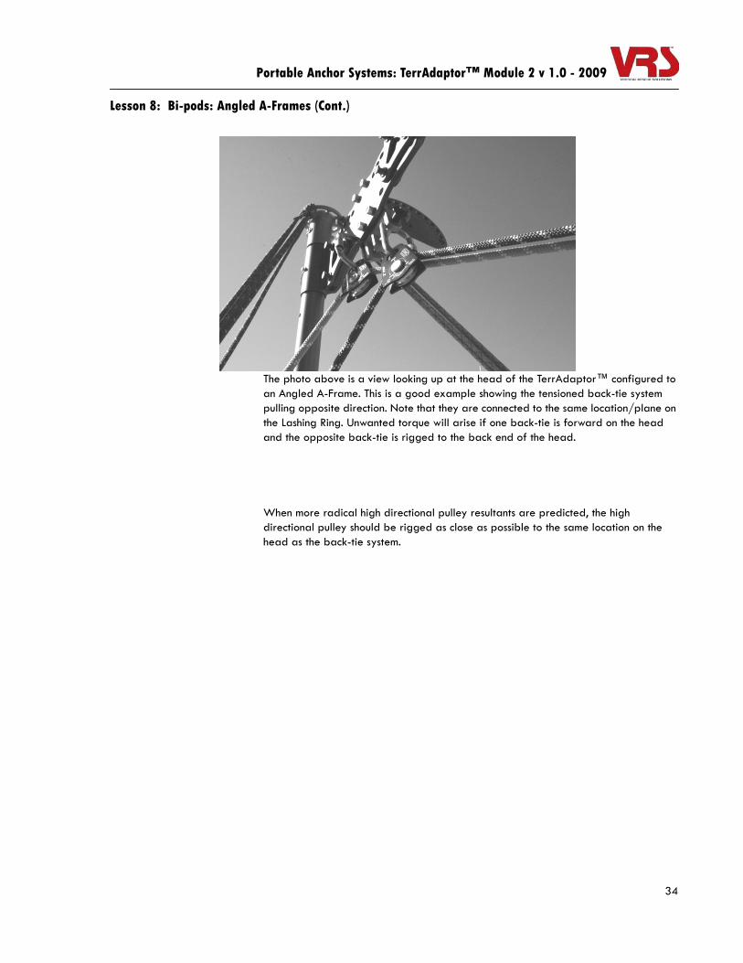
The photo above is a view looking up at the head of the TerrAdaptor™ configured to an Angled A-Frame. This is a good example showing the tensioned back-tie system pulling opposite direction. Note that they are connected to the same location/plane on the Lashing Ring. Unwanted torque will arise if one back-tie is forward on the head and the opposite back-tie is rigged to the back end of the head.
When more radical high directional pulley resultants are predicted, the high directional pulley should be rigged as close as possible to the same location on the head as the back-tie system.
35
Lesson 8: Bi-pods: Angled A-Frames (Cont.)
Portable Anchor Systems: TerrAdaptor™ Module 2 v 1.0 - 2009
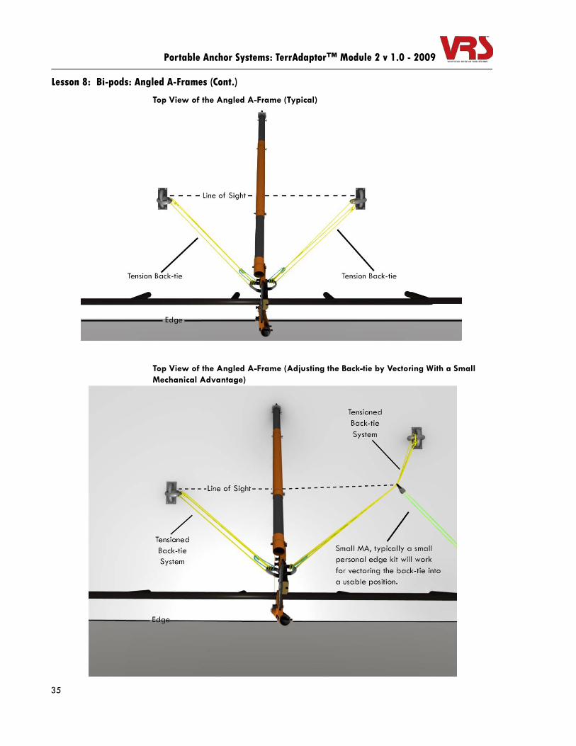
Top View of the Angled A-Frame (Typical)
Top View of the Angled A-Frame (Adjusting the Back-tie by Vectoring With a Small Mechanical Advantage)

36
Portable Anchor Systems: TerrAdaptor™ Module 2 v 1.0 - 2009
Lesson 9: Mono-pods/Gin Poles
By the end of this lesson, you should expect to understand:
• When the use of a Gin Pole (or Mono-pod) would be the best high directional portable anchor option
• Rigging tips and techniques that are unique to the use of a Gin Pole
Benefits of the Gin Pole Configuration
The Gin Pole is the lightest and arguable the least complex high directional portable anchor system. When constructed properly, the Gin Pole is a remarkably strong anchor option. Compression and tensile forces must be finely tuned to keep the Gin Pole high directional anchor system in a swiss state.
Gin Poles

Portable Anchor Systems: TerrAdaptor™ Module 2 v 1.0 - 2009

Appendix

Portable Anchor Systems: TerrAdaptor™ Module 2 v 1.0 - 2009

Portable Anchor Systems: TerrAdaptor™ Module 2 v 1.0 - 2009
TerrAdaptor™ Module 2 - Written Exam (25 points total)Please circle the correct answer
1. To study vectors is to study the physical qualities of force that has both direction and magnitude. (1pt)
a. True
b. False
2. A force vector may be graphed or represented as a simple arrow, also more commonly referred to in math as component. This component will always indicated the direction of the force. (1pt)
a. True
b. False
3. The shorter component will always have a greater magnitude. In the example below, the component on the left has approximately twice the magnitude as the one on the right. (1pt)
a. True
b. False
4. The resultant is the net force of an angle two components create. (1pt)
a. True
b. False
5. The center of any tensioned pulley should point to the exact location and direction of the resultant force at work on the associated anchor. (1pt)
a. True
b. False
For questions 6 through 12: Give a field approximation of the percentage of the load that the
stated pulley resultant angle applies to the anchor. (7pts)
6. 0o ______%
7. 30o ______%
8. 60o ______%
9. 90o ______%
10. 120o ______%
11. 150o ______%
12. 175o ______%

TerrAdaptor™ Module 2 - Written Exam (25 points total) (Cont.)
Portable Anchor Systems: TerrAdaptor™ Module 2 v 1.0 - 2009
For questions 13 through 19: Give a field approximation of the percentage of the load that the
stated angle of a 2x1 multipoint anchor system applies to each anchor. (7pts)
13. 0o ______%
14. 30o ______%
15. 60o ______%
16. 90o ______%
17. 120o ______%
18. 150o ______%
19. 175o ______%
20. Friction is a force of resistance between two objects that tends to oppose any motion. (1pt)
a. True
b. False
21. Static friction may be defined as: (1pt)
a. The force that tends to stop an object that is moving.
b. The force wanting to slow an object in motion.
c. The force that tends to counter the motion of an object that is in a state of rest.
d. All of the above.
e. Only a and b.
22. Kinetic friction may be defined as: (1pt)
a. The force that tends to stop an object that is moving.
b. The force wanting to slow an object in motion.
c. The force that tends to counter the motion of an object that is in a state of rest.
d. All of the above.
e. Only a and b.
23. The coefficient of friction may be defined as: (1pt)
a. The ratio of the applied force needed to move the object divided by the normal force between the object and the surface.
b. The force that slows an object in motion.a. The force that tends to counter the motion of an object that is in a state of rest.b. All of the above.
TerrAdaptor™ Module 2 - Written Exam (25 points total) (Cont.)
Portable Anchor Systems: TerrAdaptor™ Module 2 v 1.0 - 2009
24. The SSSF is the ratio of the overall rope system divided by the load during a static state (no movement). This is based on the weakest component and/or equipment link from the anchor to the load. (1pt)
a. True
b. False
25. The DSSF is the ratio of the overall rope system divided by the load plus all other physical factors during the predicted greatest moment of system stress, typically during the start of the hauling process of a rescue requiring a raising system. (1pt)
a. True
b. False

Portable Anchor Systems: TerrAdaptor™ Module 2 v 1.0 - 2009

VERTICAL RESCUE SOLUTIONS BY PMI
WAIVER OF LIABLITY/CONSENT FOR PARTICIPATION
WARNING!
All activities pertaining and relating to climbing, mountaineering, work at height, and rescue may be potentially dangerous. Injury or death could occur while engaged in these activities.
This VRS by PMI Course is designed to inform and familiarize you with the best use of PMI manufactured and/or distributed equipment. These operations will be run with full attention to safety. However, due to the nature of on‐rope activities, VRS, PMI, our consultants or instructors, nor anyone else can guarantee your safety.
Your participation, either as observer or as participant, must be undertaken at your own risk. You are welcome to observe the demonstrations and operations, or you may participate in these activities upon the invitation of those in charge of the course, at your own risk.
ACKNOWLEDGEMENT AND ASSUMPTION OF RISKS:
• I understand and am aware that there (are) may be certain risks involved in activities related to any instruction of work at height, rescue, and related activities, including the risk of physical injury and death.
• I hereby recognize, acknowledge, accept and assume such risks. I do not need to be warned as to any potential dangers as I am fully aware of such potentially dangerous conditions.
• I hereby verify that, to the best of my knowledge, I am free from any physical/medical condition(s) which would interfere with my ability to work at height in a safe and satisfactory manner, or put myself or others at risk, including but not limited to:
• Pregnancy • High blood pressure • Influence of Drugs or Alcohol • Diabetes
• Dizziness or Difficulty With Balance • Epilepsy, Fits, Blackouts • Fear of Heights or Vertigo • Heart Disease
• Impaired Limb Function • Psychiatric Illness
• VRS by PMI Pigeon Mountain Industries endeavor to provide quality service to our customers. However, VRS by PMI and Pigeon Mountain Industries do not
guarantee the accuracy or completeness of any information in, or provided in connection with, services provided. VRS by PMI and Pigeon Mountain Industries are not responsible for any errors or omissions, or for the results obtained from the use of such information. I am aware and have been advised that VRS by PMI and Pigeon Mountain Industries do not guarantee the safety of myself and those participating in the program.
RELEASE IN FULL I hereby on my own behalf and on behalf of my heirs and assigns do forever release and discharge VRS by PMI and Pigeon Mountain Industries, as well as any of their agents, employees, representatives, instructors or volunteers (hereinafter referred to as the Released Parties) from any and all claims of any type for injuries, damages or even death whether caused by the negligence or other wrongful conduct of any of the Release Parties. I agree to fully indemnify and hold harmless the Released Parties for any and all clams of any type which may be presented against the Released Parties for any claim or lawsuit for injuries or damages arising out of my voluntary participation in the activities conducted by VRS by PMI and Pigeon Mountain Industries. I understand that I am releasing any right that I, my estate, heirs, or assigns might have to sue any of the Released Parties and I do this of my own free will in consideration for being allowed to participate in those activities conducted by the Release Parties on the __________ day of __________, 200___ at ___________. I authorize and release to VRS by PMI and Pigeon Mountain Industries the use of my image and any photographic or video recording taken by VRS by PMI or Pigeon Mountain Industries, of any activities in which I participate. I agree to indemnify and hold harmless VRS by PMI and Pigeon Mountain Industries, their employees, agents, volunteers from all claims, damages, losses, injuries and expenses arising out of or resulting from my participation in these activities. In short, I cannot sue VRS by PMI or Pigeon Mountain Industries Inc, and if I do, I cannot collect any money. I authorize and release to VRS by PMI and Pigeon Mountain Industries the use of my image in any photograph or video recording taken by VRS by PMI or Pigeon Mountain Industries. I have read the above statements and understand them. I understand this is a legal document and that by signing it I am giving up my right to sue or otherwise make any claim against Vertical Rescue Solutions by PMI or Pigeon Mountain Industries Inc. or any of its volunteers, employees, agents, leaders, instructors, guides, officers, directors or representatives which may arise during my participation in any activities of VRS by PMI or Pigeon Mountain Industries, Inc. Signed Printed Name Date Address Telephone
Employer City, State Witness: VRS by PMI representative or employee: Signed Printed Name


![HDA Design anchor - Motek AS€¦ · Anchor bolt Nominal tensile strength f uk [N/mm²] 800 800 800 ... HDA Design anchor 09 / 2012 77 Anchor TE 24 a) TE 25 a) Anchor Anchor. HDA](https://static.fdocuments.us/doc/165x107/5b34310d7f8b9a436d8bbdfd/hda-design-anchor-motek-as-anchor-bolt-nominal-tensile-strength-f-uk-nmm.jpg)