PORT ABLE EQUIPMENT FOR BOREHOLE GEOPHYSICAL EXPLORATION
27
UN I TED STATES DEPARTMENT OF THE INTERIOR GEOLOGICAL SURVEY PORT ABLE EQUIPMENT FOR BOREHOLE GEOPHYSICAL EXPLORATION . I I 1 HYDROLOGIC LABORATORY I Denver, Colorado
Transcript of PORT ABLE EQUIPMENT FOR BOREHOLE GEOPHYSICAL EXPLORATION

UN I TED STATES
DEPARTMENT OF THE INTERIOR
GEOLOGICAL SURVEY
PORT ABLE EQUIPMENT
FOR
BOREHOLE GEOPHYSICAL
EXPLORATION
. I
I 1 HYDROLOGIC LABORATORY I
Denver, Colorado
•
•
•
UNITED STATES DEPARTMENT OF THE INTERIOR
GEOLOGICAL SURVEY
PORTABLE EQUIPMENT FOR BOREHOLE
GEOPHYSICAL EXPLORATION
By A. I. Johnson
US.~~~CALSURVEY WRD,UBRARY 505 MARQU.ETTI: NW, RM 726 ALBUQUERQUE; N.A\ 87102
U.S. GEOU>GICAL SURVEY OPEN-FILE REPORT
Hydrologic Laboratory Denver, Colorado
1963

•
•
•
CONTENTS
Page
Introduction --------------------------------------------------- 1 Portable reels ------------------------------------------------- 1 Exploration equipment ------------------------------------------ 4
Depth-to-water -------------------------------------------- 4 Fluid conductivity ---------------------------------------- 5 Collection of water samples ------------------------------- 5 Fluid velocity -------------------------------------------- 8 Borehole diameter ----------------------------------------- 11
Summary -------------------------------------------------------- 11 References ----------------------------------------------------- 14 Appendix -----------.------------------------------------------ -- 15
Beading of suspension cable ------------------------------- 15 The measuring wheel ---------------------------~-----·----- 16 Assembling cable-end fitting ------------------------------ 17 Installation of Au meter in carrier tube ------------------ 20 Operation of well caliper --------------------------------- 22
Figure 1. 2. 3. 4.
5. 6.
ILLUSTRATIONS
Large and small capacity portable borehole reels ---Powered reels for borehole exploration -------------Accessories for portable borehole exploration reel -Results of conductivity electrode surveys for salt-
water leaks --------------------------------------Water samplers -------------------------------------Au flow meter ---------------------------------------
2 3 3
6 7 9
7. Calibration curve for Au flow meter and typical velocity survey ----------------------------------- 10
B. Packing gland assembly for shutting off flowing artesian well ------------------------------------- 12
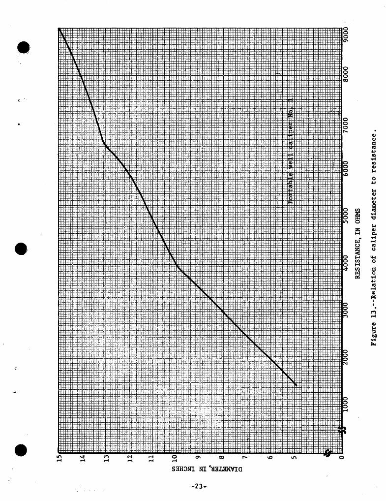
9. Borehole caliper for portable reel -----------~------ 13 10. Measuring wheel ------------------------------------- 16 11. Tool kit -------------------------------------------- 17 12. Cable-end fitting assembly -------------------------- 18 13. Relation of caliper diameter to resistance ---------- 23
TABLE
Table 1. Relationship of caliper diameter to meter readings -- 24
i

•
•
•
PORTABLE EQUIPMENT FOR BOREHOLE GEOPHYSICAL EXPLORATION
By A. I. Johnson
Introduction
Borehole geophysical exploration can yield data interpretable in ter~ of aquifer depth and continuity and in terms of well construction and condition. The extent to which borehole geophysical methods may be used to solve any given ground-water problem is dependent upon the degree to which those methods provide information on the geophysical exploration controls.
Portable equipment for bore-hole geophysical exploration is rather limited in availability and adaptability at present. That equipment presently available consists of reels and accessories for determining (1) depth to water, (2) conductivity of the borehole water (varies with mineral content of the water), (3) borehole water quality by collection of water samples, (4) rate of vertical flow of water in the borehole, and (5) diameter of the borehole. Velocity-meter logs aid in the identification of different aquifers, in determination of the hydraulic characteristics of the aquifers, and in the determination of the static hydraulic head of each of the aquifers open to the well. Borehole-diameter logs provide information on the well construction, or rock structure for open-hole wells, and enable calculation of accurate flow rates from velocity-meter logs (by correcting flow rate by area of borehole.) Conductivity logs assist in locating salt-water leaks through a well casing and determine the relative salinity of the water in aquifers penetrated by the well.
Portable Reels
Several types of portable wells have been developed for deep-well exploration. One type can use 1,000 to 3,000 feet of Ellsworth 0.08-inch cable, and-the other type uses 500 to 1,000 feet of the same cable. (See fig. 1.) The Atomic Energy Commission has developed a large powered reel for use at the National Reactor Testing Station, Idaho (fig. 2a) and Mr. F. C. Koopman of the Hydrologic Laboratory has developed a smaller powered reel, both capable of holding 2,000 feet of cable (fig. 2b). The reels are complete with accessories. (See fig. 3.)
-1-

(a)
(b)
Figure 1.--Large and small capacity portable bor eho l e exploration reels . (a) Knocked-down for carrying; (b) Set up for operation.
-2-

(a) (b)
Figure 2.--Powered reels for borehole exploration: (~) developed at National Reactor Testing Station, Atomic Energy Commission, Idaho Falls, Idaho, and (E) developed at Hydrologic Laboratory, U.S. Geological Survey, Denver, Colo.
Figure 3 . --Accessories for portable borehole exploration reel. These accessories are comprised of the following items: (a) Steel cylinder (25-pound) for clearing trash from wells. (b) Deepwell current meter (3-inch diameter). (c) Deep-well currentmeter tube. Ball valves furnished with this tube enable one to convert it to a 1-gallon "point'' sampler. (d) Water sampler, 1-quart, with ball valves, for "point" sampling. (e) Electrode (3/4 inch) for locating surface of water. (f) Electrode (1~-inch) serves same purpose as (e) but has greater weight and produces more voltage. (g) Voltmeter (1000-ohms-per-volt, 0-1 volt range) for use with items (e) and (f). (h) Repair kit.
-3-

•
•
•
Exploration Equipment
Salt-water leaks in a well may be located by pumping the well and collecting water samples for conductivity determinations. Exploration methods have been amply discussed by Livingston (1938, 1940, 1942, 1954), and Livingston and Lynch (1937), and Fiedler (1933). The information obtained from such pumping tests make it possible to estimate the salinity of the contaminating water (from its conductivity), the rate of leakage, and the depth of contamination.
For a more detailed analysis of leaky well casings or a detailed study of salt-water contamination of fresh ground-water aquifers, borehole geophysical exploration may be required. The basic methods of exploration possible with the portable exploration reels and accessory equipment were described in the introduction.
Depth-to-water
There are two depth-to-water electrodes available, 3/4-inch and 1~-inch diameter. Both use a magnesium electrode point which provides enough voltage to actuate the volt meter without use of batteries.
Before using the magnesium electrode, either clean with sand paper or soak the magnesium element in water for about 5 minutes. A coating forms on the magnesium while in storage that tends to decrease its normal electrolytic activity. When a poor electrical response occurs, soaking the magnesium should be given first consideration. Sprinkling salt on it when wet also tends to increase the voltage produced at least until the salt becomes washed off.
Always retract the magnesium element before screwing into the cap the part that holds this element.· Too much pressure exerted against the head of the wood screw within the cap may cause damage to the copper wires that come in contact with the screw. Thus, it is dangerous to attempt to assemble the cap with the part holding the magnesium element if the magnesium element protrudes upward to any appreciable extent. After assembling the parts, gently advance the magnesium element with a screw driver until you feel it make firm contact against the head of the wood screw. If the meter should not register at all when the electrode is in water, check to be sure that this last operation--advancing the magnesium element into contact position--has not been overlooked.
The "zero" of the cable occurs at a slightly different position for the 3/4-inch electrode than for the 1\-inch electrode. In the former instance, the meter responds when the water reaches the lower edge of the brass cap, whereas in the latter instance, the meter responds when the water reaches the lowest surface of the magnesium element.
-4-

•
•
•
The 1\-inch electrode·can be used either with or without the lower end. That part merely serves to provide additional weight when needed. The two holes at the lower end of the black nylon plastic sleeve on the 3/4-inch electrode are for convenience in tying a weight thereto if such additional weight is desirable.
Fluid Conductivity
The exact depth to a point of leakage or to a salt-water-fresh water interface may be obtained by logging a well with conductivity electrodes. The conductivity varies primarily with the mineral content of the water. Livingston and Lynch (1937) first used this type of equipment in 1930 to determine the location of satt-water leaks in artesian wells in Texas. It was data used and discussed by Fiedler (1933), Stringfield (1933), and Livingston and Bridges (1936). Since that time undoubtedly it has been used many times in ground-water studies.
The equipment consists of a pair of closely-spaced electrodes attached by means of the reel's two-conductor cable, to an ammeter or ohmmeter and battery or generator at the surface. The electrodes may be mounted in the top of the water-sampling tube or used as separate units as desired. The electrodes may have a separation of t inch to ~ inch and use dry cells having a potential of about 3 volts. The sheave of the portable reel indicates the depth of the electrode at all times so values of fluid conductivity (or its reciprocal, resistivity), are recorded for various depths. This data is usually plotted on arithmetic graph paper with depth as ordinate and conductivity as abscissa. (See figure 4.)
Because variation in water temperature causes a variation in the conductance, the readings of the milliameter are only relative. If true water conductivity is desired, the temperature of the water at all depths in the well must be known (within 1°F). However, the main purpose of the conductivity survey is to determine the depth to water of different quality and the true quality of that water may then be determined from a sample subsequently collected by the water-sampler survey.
Collection of Water Samples
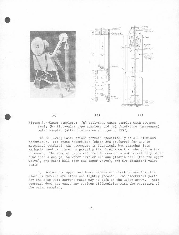
A water sampler is used to obtain a sample of the contaminating water at the depth determined significant from the conductivity survey. Livingston and Lynch (1937) and Livingston (1954) described several types of water samplers. The sampler furnished with the portable reel is of the ball-valve type and may be used to obtain a water sample at any desired depth below the water surface. (See figure 5.)
-5-

I 0\ I
•
~ Zt-w (/')u.J <tu.. u IJ..~ O_j a..w o> 1-W ~-~
0 gz W:::l coo It§ 1-tCl.<{ w 0
MILLIAMPERES . 24 26 28 30 32 34 36
•
MILLIAMPERES MILLIAMPERES 24 26 28 30 32 34 36 38 40 42 24 26 28 30 32 34
Q
a_-~ ~0 <({l: _j(!)
~~ oo a..Cl:l g~
~f3 g~ w~ CD,
IS? ~-~~ ow
lL.
z
I
I -Leak
...........
~
"--
I -
I
I
I
'eak
Le!Jk
---
~ (!)~ zo u;~ s~ u..~ oo a..QJ g~
~~ g~ ~~ ~~ CltWl&J Ol&J
LL
z
~ . Leak-
... ~
r -____ c____
Figure 4o--Results of conductivity electrode surveys for salt~water leakso [After Livingston and Lynch, 1937]
•
36 38 0
50
100
150
200
250
300
350
400
450
500
I ~
·, l ~~ r ,_,·~ ·~§ ,y;'
Seats j .· "'""'" (a) (b) (c)
Figure 5.--Water samplers: (a) ball-type water sampler with powered reel; (b) flap-valve type sampler; and (c) thief-type (messenger) water sampler (after Livingston and Lynch, 1937).
The following instructions pertain specifically to all aluminum assemblies. For brass assemblies (which are preferred for use in motorized outfits), the procedure is identical, but somewhat less emphasis need be placed on greasing the threads on the tube and in the "crowns". The special parts required to convert aluminum velocity meter tube into a one-gallon water sampler are one plastic ball (for the upper valve), one metal ball (for the lower valve), and two identical valve seats.
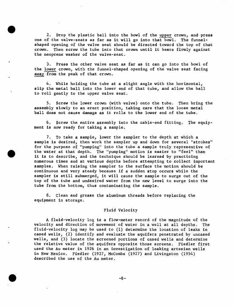
1, Remove the upper and lower crowns and check to see that the aluminum threads are clean and lightly greased. The electrical parts for the deep well current meter may be left in the upper crown, Their presence does not cause any serious difficulties with the operation of the water sampler.
-7-
•
•
•
2. Drop the plastic ball into the bowl of the upper crown, and press one of the valve-seats as far as it will go into that bowl. The funnelshaped opening of the valve seat should be directed toward the top of that crown. Then screw the tube into that crown until it bears firmly against the neoprene washer of the valve-seat.
3. Press the other valve seat as far as it can go into the bowl of the lower crown, with the funnel-shaped opening of the valve seat facing away from the peak of that crown.
4. While holding the tube at a slight angle with the horizontal, slip the metal ball into the lower end of that tube, and allow the ball to roll gently to the upper valve seat.
5. Screw the lower crown (with valve) onto the tube. Then bring the assembly slowly to an erect position, taking care that the loose metal ball does not cause damage as it rolls to the lower end of the tube.
6. Screw the entire assembly into the cable-end fitting. The equipment is now ready for taking a sample.
7. To take a sample, lower the sampler to the depth at which a sample is desired, then work the sampfer up and down for several 11 strokes" for the purpose of "pumping,. into the tube a sample truly representive of the water at that depth. The 11 pumping" motion is easier to "feel" than it is to describe, and the technique should be learned by practicing numerous times and at various depths before attempting to collect important samples. When raising the sampler to the surface the motion should be continuous and very steady because if a sudden stop occurs while the sampler is still submerged, it will cause the sample to surge out of the top of the tube and undesired water from the new level to surge into the tube from the bottom, thus contaminating the sample.
8. Clean and grease the aluminum threads before replacing the equipment in storage.
Fluid Velocity
A fluid-velocity log is a flow-meter record of the magnitude of the velocity and direction of movement of water in a well at all depths. The fluid-velocity log may be used to (1) determine the location of leaks in cased wells, (2) identify and evaluate the aquifers penetrated by uncased wells, and (3) locate the screened portions of cased wells and determine the relative value of the aquifers opposite those screens. Fiedler first used the Au meter in 1926 in an investigation of leaking artesian welis in New Mexico. Fiedler (1927, McCombs (1927) and Livingston (1954) described the use of the Au meter .
-8-

The Au meter consists of a helical turbine mounted on a shaft supported on a frame inside a 3-inch diameter brass tube and with the long axis, or axis of rotation parallel to the direction of flow. (See figure 6 .)
Figure 6.--Au flow meter
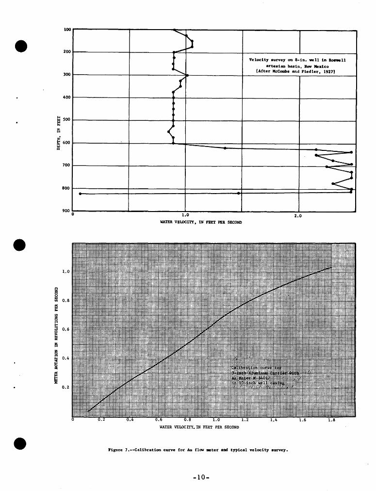
The meter shaft is geared to a commutator head which causes a signal for each revolution to be transmitted through the electrical supporting cable up to battery-powered headphones at the surface (Other commutator heads provide signals each fifth or tenth revolution). The signals are counted for a time interval selected on a stopwatch and the number of revolutions per second is converted to velocity in feet per second (or minute) by means of a calibration curve. (See figure 7.) Each meter should have its individual rating curve from a hydraulic laboratory, while mounted in its aluminum carrier tube and in the size and type of casing common to the project area.
To log a well, the flow-meter is lowered into the well to the desired depth, usually at intervals of 10 to 15 feet, and the revolutions per second recorded. The data for the downward traverse should be checked with data for the upward traverse. The direction of flow of the water may be determined by slowly raising and lowering the meter in the well. The meter will have a lesser measured velocity as it moves in the direction of the flowing water.
The velocity log plotted on arithmetic graph paper, with depth as the ordinate and flow velocity as the abscissa. The direction of flow should be indicated by arrows at the appropriate locations on the log.
-9-
100
• 200
~
J _,... ~ Velocity aurvey on 8-in. vell in lloevell
300
4 arteaian basin, New Mexico
4~ [After McC~a and Fiedler, 1927)
j 400
fo< 500 E ~
:i t 600 ~ ~ Q
700 ~
800 < .. ...
900 0 1.0 2.0
WATER VBLOCI'l'Y, Df FEET PER. SBCOND
• 1.0
~ u ~ 0.8 ell
f:i Po
ell a § 0.6 g :! j!:j
s 0.4 !2
~ P4
~ 0.2
1.8
WATER VELOCITY.IN FEET PER SECOND
• Figure 7.--Calibration curve for Au flow meter and typical velocity aurvey.
-10-

•
•
•
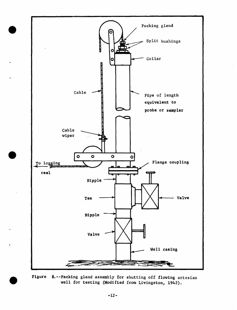
Velocity surveys may be made on flowing wells or nonflowing wells. There is usually only small clearance in a pumped well and it would be dangerous to use the Au meter in the well with the pump operatingo Probably the most convenient method of flow-meter logging a nonflowing well is to put water in at a constant rate, from another well source or from a tank trailer or trucko To determine leakage in a flowing well, it may be necessary to close in the well and log through a packing gland (fig. B)o A velocity survey made while a well is flowing or is pumped at a moderate rate may identify (1) the aquifer zones contributing to the well discharge, (2) the thickness of the zones, and (3) the relative yield at that discharge rate.
Because the velocity of the water in the well is in proportion to the cross-sectional area of the casing or hole, a borehole-diameter survey is usually requiredo The velocity data from a calibrated meter may be converted to flow rate in gallons per minute or cubic feet per second if the diameter of the well at all depths is known.
Borehole Diameter
Many cased wells are constructed with several different sizes of casing and uncased wells in rock varying in qiameter with the degree to which the rocks resist the abrasion and solution caused by the drilling actiono Thus, borehole-diameter logging may be necessary for calculation of true flow rates, for identifying the most likely zones for discharge of the aquifer into the well, and for location of holes in the casing.
The variation of borehole diameter with depth is measured by means of an instrument called a caliper (figo 9). The caliper is a system of arms which press against the wall of the casing or hole. As the arms move in and out in response to the changing diameter of the borehole, a variable resistance is actuated. The electrical resistance thus varies with diameter. The caliper is lowered into the borehole to the bottom, ·and, as it makes the upward traverse, the resistance (or diameter) variation is recorded by the instruments at the land surfaceo The appendix contains specific instructions for operation of the caliper shown in figure 9.
Summary
The methods of exploration described above are those readily available to the hydrologist needing portable inexpensive equipment. Used properly these simple investigative tools can provide valuable information on the occurrence, quality, and movement of ground-water, on the condition and·construction of wells or test holes, and on the characteristics of the geologic formations encountered. MOre detailed information on some of the more sophisticated methods for borehole geophysical exploration may be found in reports by Jones and Skibitzke (1956), Patten and Bennett (1962), and Johnson (1963)0
-11-
•
•
•
reel
Cable
Cable wiper
-~--
Nipple
Tee
Nipple
Valve
0
Packing gland
Split bushings
Collar
Pipe of length
equivalent to
probe or sampler
Flange coupling
Valve
Well casing
Figure a.--Packing gland assembly for shutting off flowing artesian well for testing (Modified from Livingston, 1942).
-12-

·e
I
Caliper
Hole diameter (inches)
0 5 10 15
Caliper log
500'
1,000'
Figure 9 , --Bore hole caliper for portable reel,
-13-

•
•
References
Fiedler, Ao G., 1927, The Au deep-well current meter and its use in the
Roswell artesian basin, New Mexico: UoSo Geol. Survey Water-Supply
Paper 596-A, p. 24-32.
_____ 1933, Deep-well salinity exploration: Am. Geophys. Union Trans.,
14th Ann. Meeting, Po 478-4800
Johnson, A. I., 1963, Geophysical logging of boreholes for hydrologic
studies: UoSo Geol. Survey open-file rept., 10 Po
Jones, P. H., and Skibitzke, H. E., 1956, Subsurface geophysical methods
in ground-water hydrology: Advances in Geophysics, v. 3, Po 241-3000
Livingston, Penn, 1940, Underground leakage from artesian wells in the
Las Vegas area, Nevada~ UoS. Geolo Survey Water-Supply Paper 849-D,
p. 147-173 •
Livingston, Penn, and Bridges, To Wo, 1936, Ground-water resources of
Kleberg County, Texas: U.S. Geolo Survey Water-Supply Paper 773-D,
p. 197-2320
Livingston, Penn, and Lynch, Walter, 1937, Methods of locating salt-water
leaks in water wells: u.s. Geol. Survey Water-Supply Paper 796-A,
p. 1-20.
Livingston, Penn, and Maxey, G. B., 1944, Underground leakage from
artesian wells in the Flowell area near Fillmore, Utah: Utah
State Engineer Tech. Pubo 1, 37 p.
McCombs, John, and Fiedler, Ao G., 1927, Methods of ~xploring and repairing
leaky artesian wells: U.So Geol. Survey Water-Supply Paper 596-A, 32 Po
Patten, E. P., and Bennett, C. Do, 1962, Methods of flow measurement in
well bores~ U.S. Geolo Survey Water-Supply Paper 1544-Co
• Stringfield, Vo T., 1933, Exploration of artesian wells in Sarasota County,
Florida: Florida Geolo Survey 23d-24th Ann. Repto, 1930-1932, p. 199-277o
-14-

•
•
•
Appendix
Included in this appendix are instructions for the maintenance, repair, and operation of the particular exploration equipment designed by the U.S. Geological Survey.
Beading of Suspension Cable
Copper beads have been swaged onto the cable at various intervals for the following reasons:
1. If the cable should break or if even one or two of the outer armor wires on the cable should break and start to unstrand, there would be danger of the entire cable becoming worthless were it not for the copper beads preventing such unstranding from extending any farther than the adjacent beads.
Because damage usually occurs most frequently at the extreme lower end of the cable, a series of beads (usually about 3 of them about 10 feet apart) are located at the lower end of the cable. Thus, if the instruments should get caught in a well and failure occur at the connector, only the lower 10 feet of cable is likely to become damaged. Such accidents would normally tend to disturb the relative location of the "sensing element" with respect to the other marks on the cable. That difficulty has been largely prevented however by establishing a "zero'' mark, comprised of three closely-spaced beads at a location of from 30 to 50 feet above the lower end. The operator should measure the distance from the "sensing element" to the middle one of those three beads, and should plan to (a) set the dial of the depth indicator to read "0" when the middle bead is opposite the index on the measuring wheel (and whe~ the red groove marked "0" across the face of the wheel coincides with the center of that bead, and (b), correct the readings made on the depth indicator by the distance that has just been measured. If the top of the well casing is to be used for the "reference point", a further correction should, of course, be made to account for the distance between the measuring wheel and "reference point".
2. Slippage may occur between the cable aQd the measuring wheel, especially if the load on the cable is very light. The beads having been spaced 100 feet apart permits corrections to be made at any or all of those 100-foot points, thereby confining any accumulation of errors to that which occurs between the last 100-foot mark and the point at which the observation is made. Three conditions must be met when re-setting the measuring wheel at any of the 100-foot marks, (a), the bead must be centered over the correct red-painted groove across the measuring wheel (b), the groove must be located directly at the pointer, and (c) the hand on the depth indicator must be directly over the "zero" symbol on the inner dial of the depth indicator .
-15-

3. The "computing-typJ' depth indicator reads only to 100 feet and then repeats. The beads at each 100-foot mark provide one means for counting the number of hundreds, watching for the zero index mark to appear on the inner dial of the depth indicator provides a second means, and observing the numbers marked on the side of the measuring wheel provides a third means.
The Measuring Wheel
Distractions will occur which cause the operator of a reel to forget whether the last bead that had passed over the measuring wheel was actually counted. Numbers on the side of the wheel assist in correcting this difficulty. (See figure 10 .)
Figure 10.-Measuring wheel.
The measuring wheel is so dimensioned that with each revolution, 1-1/2 feet of 0.08" cable will have passed over it. Fifteen equallyspaced marks, each representing 0.10 foot of travel have been cut into the rim of the wheel. An important purpose of those marks is to facilitate the accurate positioning and timing of observations of rapid changes in water levels. When using the magnesium-brass electrode, and the water is rising (for example), the observer sets the electrode say 0.5 ft above the surface and observes the time the needle of the voltmeter deflects. Then by using the grooves on the wheel for this "scale" he positions the electrode a few tenths higher than before and observes the time of the next deflection of the volt meter. This process is repeated for the period of the "run".
-16-

Assembling Cable-End Fitting
By using the proper tools (fig, ll) and the following step by step instructions a cable-end fitting may be easily assembled .
Figure 11 . --Tool kit .
l, Pull the damaged 0,08'' Ellsworth cable through the cable-end fitting (fig . 5) before cutting off the damaged section,
2. Cut cable off cleanly so as to provide a non-ravelled end. This is done by taking about two turns around the cable with electrical or Masking tape and cutting the cable off through the midpoint of this tape, making the angle of the cut about 45° with the centerline of the cable.
3. Thread the cable through the upper end of the brass cable-end fitting. It will probably be necessary to remove the tape and carefully hold the ends of the cable from fraying prior to pushing the cable through the small hole in the fitting. If it frays too much as it emerges from the other end of the fitting, it may be preferable to make another cut (above the frsyed portion) as explained above, rather than to attempt winding the loose ends back into place.
-17-
I ~ 0) I
•
0. 08" Ellsworth \
Cable
•
Cable-end fitting
Nic.opress
•
Ends of cable bent backward and clipped off
Washer Screw
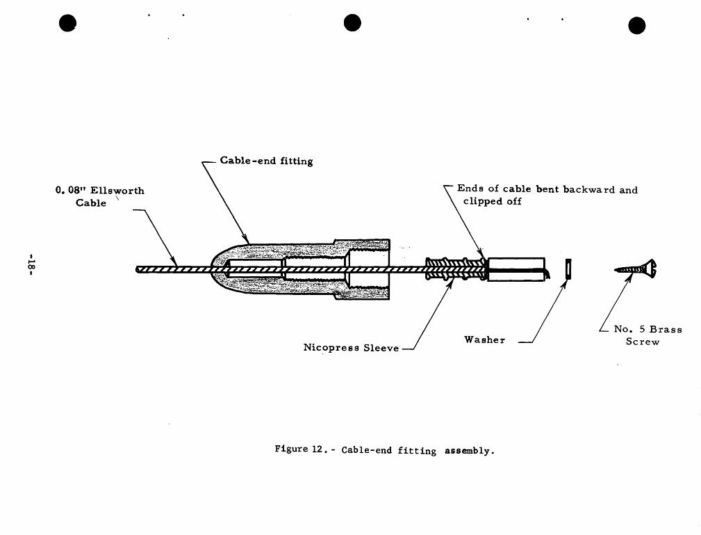
Figure 12. - Cable-end fitting assembly.

•
•
•
4. Thread the cable through one of the 7/8" long copper Nicopress sleeves. Permit the cable to extend about 1-1/4 inch beyond the sleeve and crLmp the sleeve onto the cable with the Nicopress tool. Use the "D" section of the tool, and make three "squeezes",--one near each end, and one near the middle. Then give it one additional "squeeze" near the middle, with the ''C" section of the tool. This sleeve must become seated within the deepest recess of the cable-end fitting. If, therefore, finlike protuberances should became formed as a result of the squeezing operation, they may prevent the sleeve from slipping freely into the recess and they should be filed off (orsqueezed down) before proceeding with the assembly work.
5. Unstrand the steel armor of the cable back as far as the Nicopress sleeve, and bend the wires back sharply at the outer end of the sleeve. With the cable-cutting tool, trim off the bent armor wires as closely as possible to the end of the sleeve, letting the nylon-insulated copper strand project therefrom.
6. With a match (or cigarette-lighter), heat the outer end of the nylon-insulated wire up to about 1/4" or 3/8" from the Nicopress sleeve until the nylon insulation tends to "boil", then quickly wipe it off with the wiping cloth. Repeat this two or three times to be sure that the nylon is entirely removed from the copper wire, but leaving about 1/4 inch of that insulation still intact near the sleeve where it will help protect the inner conductor from making contact with the outer armor wires. Then apply the abrasive cloth to the exposed copper wire so as to assure good electrical contact with the brass wood screw.
7. Slide the plastic sleeve over the exposed inner conductor. Advance that sleeve until it bears against the outwardly-bent steel armor wires.
8. Cut off whatever portion of the copper wire protrudes more than about 3/32 inch from the outer end of the plastic tube.
9. Thread the #5 Brass Screw through the washer, watching to see that the countersunk face of the washer is directed toward the head of the screw, and push the end of the screw for a distance of about 1/8 inch to 1/4 inch into the plastic tube alongside the copper wire. (Do not push it in too far or it will tend to swell the OD of the tube so much that the tube will not seat properly within its recess in the cable-end fittings).
10. In the event that instruments are to be installed onto the cableend fitting that are extremely sensitive, and might be affected by the stray currents that might occur if water from the well penetrated into the inside of the fitting, it is believed that packing the inner recesses of the fitting with water repellent silicone grease before performing the next operation will be beneficial .
-19-

•
•
•
11. Now guide the end-assembly into the cable-end fitting. Do this by "pushing" it from the outer end (preferably with a screw driver), rather than by "pulling" it from the cable end. If ''pulled" into place, the plastic sleeve tends to slip off the end of the wire, and there is no good method of getting the plastic sleeve properly relocated without cutting the cable and starting the entire operation over "from scratch".
12. When the Nicopress sleeve and the plastic sleeve are properly seated, advance the brass screw the rest of its length into the plastic. This swells the plastic tube so as to help seal the inside of the fitting against the intrusion of water from above. Stop tightening the screw when its head (and the washer) rest firmly against the end of the plastic tube. Turning it too much tends to shear off the copper wire within the plastic tube.
Installation of Au Meter in Carrier Tube
The Au meter should be installed in the aluminum carrier tube so it will be protected during logging operations. The meter is installed in the tube by the following procedure:
1. Check to see that the preferred contact chamber is on the meter, see that the binding post on the contact chamber is oriented in line with the cross brace at the top of the meter, and that the set screw that holds that contact chamber is tight. Also see that the contact wire within the contact chamber bears against the eccentric with the desired amount of pressure.
2. Note that there is a stainless steel set screw in the upper "crown". See that this set screw does not protrude into the inner recesses of the "crown".
3. There is a knurled nut located just below the shaft of the rotor of the meter which, when screwed in one direction, will raise the rotor off its pivot, and restrain it from revolving. When the nut is screwed as far as it will go in the other direction, the meter is in the operating condition. Before assembling the meter within the 3-inch pipe, one should always see that the nut is screwed to the operating position. It is equally important that the nut is screwed in the opposite direction when the meter is packed for storage or shipment.
4. Presumably both the upper and lower "crowns" are screwed onto the current meter tube at the beginning of the procedure that we are about to describe. Unscrew the upper crown.
-20-

•
•
•
5. To assemble the meter within the tube, first see that the wiring connections needed for carrying the electrical current from the inner conductor of the cable to the terminal of the meter are installed in t,he crown. The next step is to check to see that the threads on the tube and in the ''crown" are clean of dirt and grit, and that a thin film of the Alcoa Thread Grease has been applied to them. Ungreased aluminum threads are prone to lock together if not greased, and much trouble can result from overlooking this step. Then connect the wire terminal to the binding post on the meter. Next hold the upper crown upside down and slip the top end of the meter into the deepest recess into which it will fit within the crown. That position should be deep enough so that the stainless steel set screw in the rim of the crown will ~ear against the knurled ring around the upper end of the meter. Do hot fasten the set screw yet.
Second, while holding this assembly upside down, screw the tube into it. This method prevents the wire from becoming "all twisted up".
Third, (still upside down) orient the meter so that the crossrib at the top of the meter and the stainless steel set screw in the crown are in alignment, then tighten the set screw (with only moderate pressure). The set screw not only holds the meter from slipping down into the tube, but it also cuts through the paint on the meter and thus completes the electrical circuit (the paint would otherwise cause the circuit to be "open"). If the meter i.s not oriented as described, the pressure of the set screw may tend to bend out of shape the tube from which the meter is made, and thereby damage it pennanently,--so be careful!
6. Remove the thread-protecting nut from the top end of the crown and screw the tube assembly onto the cable-end fitting. Electrical contact should be made between the insulated brass screws that come together within the cable-end fitting.
7. Check the overall electrical circuit by installing the headphones (with battery) to the binding posts on the reel, and causing the rotor of the meter to revolve by blowing onto it.
When disassembling the equipment, again hold the assembly upside down, loosen the set screw, unscrew the tube from the crown and in general follow the above instructions in the reverse order. Be sure to clean the aluminum threads on the tube and on both crowns, and apply grease before re-installing the crowns for storage purposes. Don't forget to replace the thread-protecting nut at the top of the entire assembly.
-21-
•
•
•
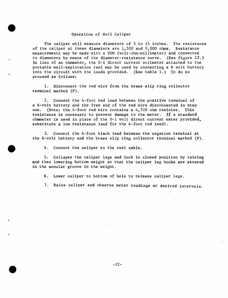
Operation of Well Caliper
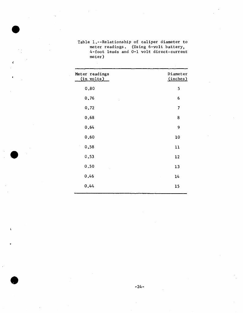
The caliper will measure diameters of 5 to 15 inches. The resistance of the caliper at these diameters are 1,500 and 9,000 ohms. Resistance measurements may be made with a VOM (volt-ohm-millimeter) and converted to diameters by means of the diameter-resistance curve. (See figure 12.) In lieu of an ohmmeter, the 0-1 direct current voltmeter attached to the portable well-exploration reel may be used by connecting a 6 volt battery into the circuit with the leads provided. (See table 1.) To do so proceed as follows:
1. Disconnect the red wire from the brass slip ring collector terminal marked (P).
2. Connect the 4-foot red lead between the positive terminal of a 6-volt battery and the free end of the red wire disconnected in step one. (Note: the 4-foot red wire contains a 4,700 ohm resister. This resistance is necessary to prevent damage to the meter. If a standard ohmmeter is used in place of the 0-1 volt direct current meter provid~d, substitute a low resistance lead for the 4-foot red lead).
3. Connect the 4-foot black lead between the negative terminal at the 6-volt battery and the brass slip ring collector terminal marked (P) .
4. Connect the caliper to the reel cable.
5. Collapse the caliper legs and lock in closed position by raising and then lowering bottom weight so that the caliper leg hooks are secured in the annular groove in the weight.
6. Lower caliper to bottom of hole to release caliper legs.
7. Raise caliper and observe meter readings at desired.intervals.
-22-
•!
'
c . '
••
(
•
!-1-H-t+t-·t-1-H- -{- . +-
-23-
,-
,-
- "i-
'::\:
r-·
0 0 0 0\
0 0 0 co
0 0 0
""
0 0 0 \0
0 0 ~
'
I~
0
Q) u c:: t1S
,&.J CD
"" CD Q) ... 0
"""' ... Q)
,&.J Q)
~ m ..... '0 ,..
~ Q) Q.
r:a .. ..... r..f
u t1S
~ u E-4 ~ Cll 0 H Cll = ~ 0
"" ,&.J
t1S r..f
Q)
~ I
' M .... G) ,.. =' ()0 .....
r;...
• (
•
•
Table lo--Relationship of caliper diameter to meter readings. (Using 6-volt battery, 4-foot leads and 0-1 volt direct-current meter)
Meter readings Diameter (in volts) (inches)
Oo80 5
0.76 6
Oo72 7
0068 8
0.64 9
0.60 10
0.58 11
0.53 12
0.50 13
Oo46 14
Oo44 15
-24-