Porsche 997 2005-2012 Table of Contents 99-9606 Dash ... · 99-9606 2 1. Remove the (1) T-30 Torx...
8
METRA. The World’s best kits. ™ metraonline.com © COPYRIGHT 2004-2016 METRA ELECTRONICS CORPORATION REV. 4/6/2016 INST99-9606 Installation instructions for part 99-9606 CAUTION! All accessories, switches, climate controls panels, and especially air bag indicator lights must be connected before cycling the ignition. Also, do not remove the factory radio with the key in the on position, or while the vehicle is running. • ISO DIN radio provision with pocket • ISO DDIN radio provision • 99-9606G - Painted gray • 99-9606B - Painted black • A) Radio trim panel • B) Radio brackets • C) Pocket • D) (4) #8 x 3/8” Phillips pan-head screws • E) (4) Phillips 5mm x 12mm flat-head screws KIT FEATURES KIT COMPONENTS WIRING & ANTENNA CONNECTIONS (sold separately) Wiring Harness: • N/A Antenna Adapter: • 40-EU10 Porsche 997 2005-2012 99-9606 A B Dash Disassembly .................................................. 2 Kit Assembly – ISO DIN radio provision with pocket...................... 3 – ISO DDIN radio provision ...................................... 3 Table of Contents • Panel removal tool • Phillips screwdriver • Torx T-15 screwdriver • Torx T-30 screwdriver • 5mm Allen wrench TOOLS REQUIRED C D E
Transcript of Porsche 997 2005-2012 Table of Contents 99-9606 Dash ... · 99-9606 2 1. Remove the (1) T-30 Torx...

METRA. The World’s best kits.™ metraonline.com © COPYRIGHT 2004-2016 METRA ELECTRONICS CORPORATION
REV.
4/6
/201
6 I
NST9
9-96
06
Installation instructions for part 99-9606
CAUTION! All accessories, switches, climate controls panels, and especially air bag indicator lights must be connected before cycling the ignition. Also, do not remove the factory radio with the key in the on position, or while the vehicle is running.
• ISO DIN radio provision with pocket• ISO DDIN radio provision• 99-9606G - Painted gray• 99-9606B - Painted black
• A) Radio trim panel • B) Radio brackets • C) Pocket • D) (4) #8 x 3/8” Phillips pan-head screws • E) (4) Phillips 5mm x 12mm flat-head screws
KIT FEATURES
KIT COMPONENTS
WIRING & ANTENNA CONNECTIONS (sold separately)Wiring Harness: • N/A
Antenna Adapter: • 40-EU10
Porsche 997 2005-201299-9606
A B
Dash Disassembly ..................................................2
Kit Assembly
– ISO DIN radio provision with pocket ...................... 3
– ISO DDIN radio provision ...................................... 3
Table of Contents
• Panel removal tool • Phillips screwdriver• Torx T-15 screwdriver • Torx T-30 screwdriver • 5mm Allen wrench
TOOLS REQUIRED
C D
E
99-9606
2
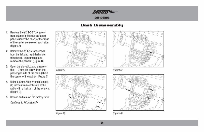
1. Remove the (1) T-30 Torx screw from each of the small carpeted panels under the dash, at the front of the center console on each side. (Figure A)
2. Remove the (2) T-15 Torx screws from the left and right dash side trim panels, then unsnap and remove the panels. (Figure B)
3. Open the gloveblox and unscrew the (1) 7mm set screw from the passenger side of the radio (about the center of the radio). (Figure C)
4. Using a 5mm Allen wrench, unlock (2) latches from each side of the radio with a half turn of the wrench. (Figure D)
5. Unsnap and remove the factory radio.
Continue to kit assembly
Dash Disassembly
(Figure B)
(Figure A)
(Figure D)
(Figure C)

99-9606
Kit Assembly
(Figure A)
(Figure A)
ISO DIN radio provision with pocket
1. Remove the metal DIN sleeve and trim ring from the aftermarket radio.
2. Attach the pocket to the radio brackets using the (4) #8 x 3/8” Phillips pan-head screws provided. (Figure A)
3. Slide the radio into the bracket/pocket assembly and then secure it using the screws supplied with the radio. (Figure A)
Note: The screws must be flush in the radio brackets in order to properly slide into the factory sub-dash. (4) 5mm x 12mm Phillips flat-head screws have been supplied if the radio does not supply these type of screws.
4. Locate the factory wiring harness and antenna connector in the dash and complete all necessary connections to the radio. Metra recommends using the proper mating adapter from Metra and/or AXXESS. Test the radio for proper operation.
5. Snap the radio into the dash, then snap the radio trim panel over the radio, and then reassemble the dash in the reverse order of disassembly.
Note: Once the radio is snapped in it will not release unless the entire radio sub-dash assembly is removed.
ISO DDIN radio provision
1. Attach the radio brackets to the radio using the screws supplied with the radio. (Figure A)
Note: The screws must be flush in the radio brackets in order to properly slide into the factory sub-dash. (4) 5mm x 12mm Phillips flat-head screws have been supplied if the radio does not supply these type of screws.
2. Locate the factory wiring harness and antenna connector in the dash, and complete all necessary connections to the radio. Metra recommends using the proper mating adapter from Metra and/or AXXESS. Test the radio for proper operation.
3. Snap the radio into the dash, then snap the radio trim panel over the radio, and then reassemble the dash in the reverse order of disassembly.
Note: Once the radio is snapped in it will not release unless the entire radio sub-dash assembly is removed.
3

METRA. The World’s best kits.™ metraonline.com © COPYRIGHT 2004-2016 METRA ELECTRONICS CORPORATION
REV.
4/6
/201
6 I
NST9
9-96
06
Installation instructions for part 99-9606
KNOWLEDGE IS POWEREnhance your installation and fabrication skills by enrolling in the most recognized and respected mobile electronics school in our industry.Log onto www.installerinstitute.com or call 800-354-6782 for more information and take steps toward a better tomorrow.
Metra recommends MECP certified technicians
IMPORTANTIf you are having difficulties with the installation of this product, please call our Tech Support line at 1-800-253-TECH. Before doing so, look over the instructions a second time, and make sure the installation was performed exactly as the instructions are stated. Please have the vehicle apart and ready to perform troubleshooting steps before calling.

METRA. The World’s best kits.™ metraonline.com © COPYRIGHT 2004-2016 METRA ELECTRONICS CORPORATION
REV.
4/6
/201
6 I
NST9
9-96
06
Instrucciones de instalación para la pieza 99-9606
¡PRECAUCIÓN! Todos los accesorios, interruptores, paneles de con-troles de clima y especialmente las luces del indicador de las bolsas de aire deben estar conectados antes ciclar la ignición. Además, no quite el radio de fábrica con la llave en la posición o de encendido ni con el vehículo funcionando.
• Provisión de radio ISO DIN con cavidad• Provisión de radio ISO DDIN• 99-9606G - Pintura gris• 99-9606B - Pintura negro
• A) Panel de moldura de radio • B) Soportes del radio • C) Cavidad • D) (8) Tornillos Phillips de cabeza troncocónica #8 de 3/8” • E) (4) Tornillos Phillips de cabeza plana de 5mm x 12mm
KIT FEATURES
COMPONENTES DEL KIT
CABLEADO Y CONEXIONES DE ANTENA (se venden por separado)Arnés de cableado: • N/A
Adaptador de antena: • 40-EU10
Porsche 997 2005-201299-9606
A B
Desmontaje del tablero ..........................................2
Ensamble del kit
– Provisión de radio ISO DIN con cavidad ................ 3
– Provisión de radio ISO DDIN ................................. 3
Indice
• Herramienta para quitar paneles • Destornillador Phillips• Destornillador Torx T-15 • Destornillador Torx T-30 • Llave Allen de 5mm
HERRAMIENTAS REQUERIDAS
C D
E

99-9606
2
1. Quite el (1) tornillo Torx T-30 de cada uno de los paneles alfombrados pequeños abajo del tablero, en el frente de la consola central de cada lado. (Figura A)
2. Quite los (2) tornillos Torx T-15 del panel de la moldura de lado izquierdo y derecho del tablero, luego suelte a presión y quite los paneles. (Figura B)
3. Abra la gloveblox, y desatornille el (1) tornillo de ajuste de 7 mm del lado del pasajero del radio (aproximadamente el centro del radio). (Figura C)
4. Use una llave Allen de 5 mm para desbloquear los (2) seguros de cada lado del radio con media vuelta de la llave. (Figura D)
5. Suelte a presión y quite el radio de fábrica.
Continúe con el ensamble del kit
Desmontaje del tablero
(Figura B)
(Figura A)
(Figura D)
(Figura C)

99-9606
Ensamble del kit
(Figura A)
(Figura A)
Provisión de radio ISO DIN con cavidad
1. Quite la manga de metal DIN y el anillo de moldura del radio de mercado secundario.
2. Coloque la cavidad en el soportes del radio con (4) tornillos Phillips de cabeza troncocónica #8 suministrados. (Figura A)
3. Deslice el radio dentro del conjunto del soporte/la cavidad y sujételo con los tornillos suministrados con el radio. (Figura A)
Nota: Los tornillos deben estar al ras en los soportes del radio para deslizarlo correctamente en el sub tablero de fábrica. Se han proporcionado (4) tornillos Phillips de cabeza plana de 5 mm x 12 mm si el radio no proporciona estos tipos de tornillos.
4. Localice el arnés de cableado de fábrica y el conector de la antena en el tablero, y haga todas las conexiones necesarias al radio. Metra recomienda que use adaptadores adecuados de acoplamiento de Metra y/o de AXXESS. Pruebe el radio para verificar que funcione correctamente.
5. Inserte a presión el radio en el tablero, luego inserte a presión el panel de la moldura del radio sobre el radio, y después vuelva a armar el tablero al revés de como lo desarmó.
Nota: Después de que el radio se haya insertado a presión, no se soltará a menos que se quite todo el ensamble del sub tablero del radio.
Provisión de radio ISO DDIN
1. Coloque los soportes del radio en la radio con los tornillos suministrados con el radio. (Figura A)
Nota: Los tornillos deben estar al ras en los soportes del radio para deslizarlo correctamente en el sub tablero de fábrica. Se han proporcionado (4) tornillos Phillips de cabeza plana de 5mm x 12mm si el radio no proporciona estos tipos de tornillos.
2. Localice el arnés de cableado de fábrica y el conector de la antena en el tablero, y haga todas las conexiones necesarias al radio. Metra recomienda que use adaptadores adecuados de acoplamiento de Metra y/o de AXXESS. Pruebe el radio para verificar que funcione correctamente.
3. Inserte a presión el radio en el tablero, luego inserte a presión el panel de la moldura del radio sobre el radio, y después vuelva a armar el tablero al revés de como lo desarmó.
Nota: Después de que el radio se haya insertado a presión, no se soltará a menos que se quite todo el ensamble del sub tablero del radio.
3

METRA. The World’s best kits.™ metraonline.com © COPYRIGHT 2004-2016 METRA ELECTRONICS CORPORATION
REV.
4/6
/201
6 I
NST9
9-96
06
KNOWLEDGE IS POWEREnhance your installation and fabrication skills by enrolling in the most recognized and respected mobile electronics school in our industry.Log onto www.installerinstitute.com or call 800-354-6782 for more information and take steps toward a better tomorrow.
Metra recomienda técnicos con certificación del Programa de Certificación en Electrónica Móvil (Mobile Electronics Certification Program, MECP).
EL CONOCIMIENTO ES PODERMejore sus habilidades de instalación y fabricación inscribiéndose en la escuela de dispositivos electrónicos móviles más reconocida y respetada de nuestra industria. Regístrese en www.installerinstitute.com o llame al 800-354-6782 para obtener más información y avance hacia un futuro mejor.
Instrucciones de instalación para la pieza 99-9606
IMPORTANTESi tiene dificultades con la instalación de este producto, llame a nuestra línea de soporte técnico al 1-800-253-TECH. Antes de hacerlo, revise las instrucciones por segunda vez y asegúrese de que la instalación se haya realizado exactamente como se indica en las instrucciones. Por favor tenga el vehículo desarmado y listo para ejecutar los pasos de resolución de problemas antes de llamar.