Porogen-based solid freeform fabrication of ... · Biomaterials 27 (2006) 4399–4408 Porogen-based...
10
Biomaterials 27 (2006) 4399–4408 Porogen-based solid freeform fabrication of polycaprolactone–calcium phosphate scaffolds for tissue engineering Mark J. Mondrinos a , Robert Dembzynski b , Lin Lu b , Venkata K.C. Byrapogu b , David M. Wootton b , Peter I. Lelkes a, , Jack Zhou b a School of Biomedical Engineering, Science and Health Systems, Drexel University, Philadelphia, PA, USA b Department of Mechanical Engineering and Mechanics, Drexel University, Philadelphia, PA, USA Received 5 November 2005; accepted 21 March 2006 Available online 5 May 2006 Abstract Drop on demand printing (DDP) is a solid freeform fabrication (SFF) technique capable of generating microscale physical features required for tissue engineering scaffolds. Here, we report results toward the development of a reproducible manufacturing process for tissue engineering scaffolds based on injectable porogens fabricated by DDP. Thermoplastic porogens were designed using Pro/Engineer and fabricated with a commercially available DDP machine. Scaffolds composed of either pure polycaprolactone (PCL) or homogeneous composites of PCL and calcium phosphate (CaP, 10% or 20% w/w) were subsequently fabricated by injection molding of molten polymer-ceramic composites, followed by porogen dissolution with ethanol. Scaffold pore sizes, as small as 200 mm, were attainable using the indirect (porogen-based) method. Scaffold structure and porosity were analyzed by scanning electron microscopy (SEM) and microcomputed tomography, respectively. We characterized the compressive strength of 90:10 and 80:20 PCL–CaP composite materials (19.571.4 and 24.871.3 Mpa, respectively) according to ASTM standards, as well as pure PCL scaffolds (2.7770.26 MPa) fabricated using our process. Human embryonic palatal mesenchymal (HEPM) cells attached and proliferated on all scaffolds, as evidenced by fluorescent nuclear staining with Hoechst 33258 and the Alamar Blue TM assay, with increased proliferation observed on 80:20 PCL–CaP scaffolds. SEM revealed multilayer assembly of HEPM cells on 80:20 PCL–CaP composite, but not pure PCL, scaffolds. In summary, we have developed an SFF-based injection molding process for the fabrication of PCL and PCL–CaP scaffolds that display in vitro cytocompatibility and suitable mechanical properties for hard tissue repair. r 2006 Elsevier Ltd. All rights reserved. Keywords: Calcium phosphate; Polycaprolactone; Composite; Scaffold; Mechanical properties; Cell proliferation 1. Introduction Tissue engineering is an interdisciplinary field that draws from materials science, cell biology, and biotechnology to synthesize effective strategies for repair or replacement of damaged or diseased tissues [1]. Typically, in vitro bone tissue engineering uses engineered 3-D scaffolds [2] made of synthetic biodegradable polymers [3] or bioceramics [4], as substrates for 3-D culture of osteoblasts or other applicable cell types. The recent application of solid freeform fabrica- tion (SFF) to manufacturing scaffolds for tissue engineering [5–8] is limited by the fact that SFF machines must be adapted to the fluid mechanical properties of each biomaterial under consideration. For drop-on-demand- printing (DDP) and fused deposition modeling, the machine parameters must match the physical properties of the build material, such as viscosity and surface tension. These properties vary greatly amongst different biomaterials, precluding the use of a single machine for direct fabrication of scaffolds from multiple biomaterials, requiring more complicated multi-nozzle designs. Therefore, it is desirable ARTICLE IN PRESS www.elsevier.com/locate/biomaterials 0142-9612/$ - see front matter r 2006 Elsevier Ltd. All rights reserved. doi:10.1016/j.biomaterials.2006.03.049 Abbreviations: Au, gold; CAD, computer-aided design; CaP, calcium phosphate; CM, compressive modulus; DDP, drop-on-demand printing; FBS, fetal bovine serum; HEPM, human embryonic palatal mesenchyme; MEM, minimum essential medium; PBS, phosphate buffered saline; PCL, polycaprolactone; Pd, palladium; SEM, scanning electron microscopy; SFF, solid freeform fabrication; UCS, ultimate compressive strength; mCT, micro computed tomography; SD, standard deviation Corresponding author. Tel.: +1 215 895 2219; fax: +1 215 895 4983. E-mail address: [email protected] (P.I. Lelkes).
Transcript of Porogen-based solid freeform fabrication of ... · Biomaterials 27 (2006) 4399–4408 Porogen-based...
ARTICLE IN PRESS
0142-9612/$ - se
doi:10.1016/j.bi
Abbreviations
phosphate; CM
FBS, fetal bovi
MEM, minimu
polycaprolacton
SFF, solid freef
mCT, micro com�CorrespondE-mail addr
Biomaterials 27 (2006) 4399–4408
www.elsevier.com/locate/biomaterials
Porogen-based solid freeform fabrication of polycaprolactone–calciumphosphate scaffolds for tissue engineering
Mark J. Mondrinosa, Robert Dembzynskib, Lin Lub, Venkata K.C. Byrapogub,David M. Woottonb, Peter I. Lelkesa,�, Jack Zhoub
aSchool of Biomedical Engineering, Science and Health Systems, Drexel University, Philadelphia, PA, USAbDepartment of Mechanical Engineering and Mechanics, Drexel University, Philadelphia, PA, USA
Received 5 November 2005; accepted 21 March 2006
Available online 5 May 2006
Abstract
Drop on demand printing (DDP) is a solid freeform fabrication (SFF) technique capable of generating microscale physical features
required for tissue engineering scaffolds. Here, we report results toward the development of a reproducible manufacturing process for
tissue engineering scaffolds based on injectable porogens fabricated by DDP. Thermoplastic porogens were designed using Pro/Engineer
and fabricated with a commercially available DDP machine. Scaffolds composed of either pure polycaprolactone (PCL) or homogeneous
composites of PCL and calcium phosphate (CaP, 10% or 20% w/w) were subsequently fabricated by injection molding of molten
polymer-ceramic composites, followed by porogen dissolution with ethanol. Scaffold pore sizes, as small as 200 mm, were attainable using
the indirect (porogen-based) method. Scaffold structure and porosity were analyzed by scanning electron microscopy (SEM) and
microcomputed tomography, respectively. We characterized the compressive strength of 90:10 and 80:20 PCL–CaP composite materials
(19.571.4 and 24.871.3Mpa, respectively) according to ASTM standards, as well as pure PCL scaffolds (2.7770.26MPa) fabricated
using our process. Human embryonic palatal mesenchymal (HEPM) cells attached and proliferated on all scaffolds, as evidenced by
fluorescent nuclear staining with Hoechst 33258 and the Alamar BlueTM assay, with increased proliferation observed on 80:20 PCL–CaP
scaffolds. SEM revealed multilayer assembly of HEPM cells on 80:20 PCL–CaP composite, but not pure PCL, scaffolds. In summary, we
have developed an SFF-based injection molding process for the fabrication of PCL and PCL–CaP scaffolds that display in vitro
cytocompatibility and suitable mechanical properties for hard tissue repair.
r 2006 Elsevier Ltd. All rights reserved.
Keywords: Calcium phosphate; Polycaprolactone; Composite; Scaffold; Mechanical properties; Cell proliferation
1. Introduction
Tissue engineering is an interdisciplinary field that drawsfrom materials science, cell biology, and biotechnology tosynthesize effective strategies for repair or replacement ofdamaged or diseased tissues [1]. Typically, in vitro bone
e front matter r 2006 Elsevier Ltd. All rights reserved.
omaterials.2006.03.049
: Au, gold; CAD, computer-aided design; CaP, calcium
, compressive modulus; DDP, drop-on-demand printing;
ne serum; HEPM, human embryonic palatal mesenchyme;
m essential medium; PBS, phosphate buffered saline; PCL,
e; Pd, palladium; SEM, scanning electron microscopy;
orm fabrication; UCS, ultimate compressive strength;
puted tomography; SD, standard deviation
ing author. Tel.: +1215 895 2219; fax: +1 215 895 4983.
ess: [email protected] (P.I. Lelkes).
tissue engineering uses engineered 3-D scaffolds [2] made ofsynthetic biodegradable polymers [3] or bioceramics [4], assubstrates for 3-D culture of osteoblasts or other applicablecell types. The recent application of solid freeform fabrica-tion (SFF) to manufacturing scaffolds for tissue engineering[5–8] is limited by the fact that SFF machines must beadapted to the fluid mechanical properties of eachbiomaterial under consideration. For drop-on-demand-printing (DDP) and fused deposition modeling, the machineparameters must match the physical properties of the buildmaterial, such as viscosity and surface tension. Theseproperties vary greatly amongst different biomaterials,precluding the use of a single machine for direct fabricationof scaffolds from multiple biomaterials, requiring morecomplicated multi-nozzle designs. Therefore, it is desirable
ARTICLE IN PRESS
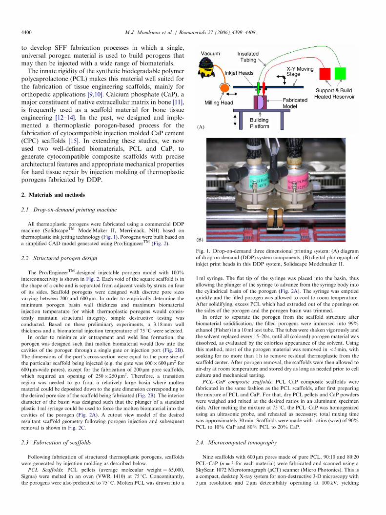
Fig. 1. Drop-on-demand three dimensional printing system: (A) diagram
of drop-on-demand (DDP) system components; (B) digital photograph of
inkjet print heads in this DDP system, Solidscape Modelmaker II.
M.J. Mondrinos et al. / Biomaterials 27 (2006) 4399–44084400
to develop SFF fabrication processes in which a single,universal porogen material is used to build porogens thatmay then be injected with a wide range of biomaterials.
The innate rigidity of the synthetic biodegradable polymerpolycaprolactone (PCL) makes this material well suited forthe fabrication of tissue engineering scaffolds, mainly fororthopedic applications [9,10]. Calcium phosphate (CaP), amajor constituent of native extracellular matrix in bone [11],is frequently used as a scaffold material for bone tissueengineering [12–14]. In the past, we designed and imple-mented a thermoplastic porogen-based process for thefabrication of cytocompatible injection molded CaP cement(CPC) scaffolds [15]. In extending these studies, we nowused two well-defined biomaterials, PCL and CaP, togenerate cytocompatible composite scaffolds with precisearchitectural features and appropriate mechanical propertiesfor hard tissue repair by injection molding of thermoplasticporogens fabricated by DDP.
2. Materials and methods
2.1. Drop-on-demand printing machine
All thermoplastic porogens were fabricated using a commercial DDP
machine (SolidscapeTM ModelMaker II, Merrimack, NH) based on
thermoplastic ink jetting technology (Fig. 1). Porogens were built based on
a simplified CAD model generated using Pro/EngineerTM (Fig. 2).
2.2. Structured porogen design
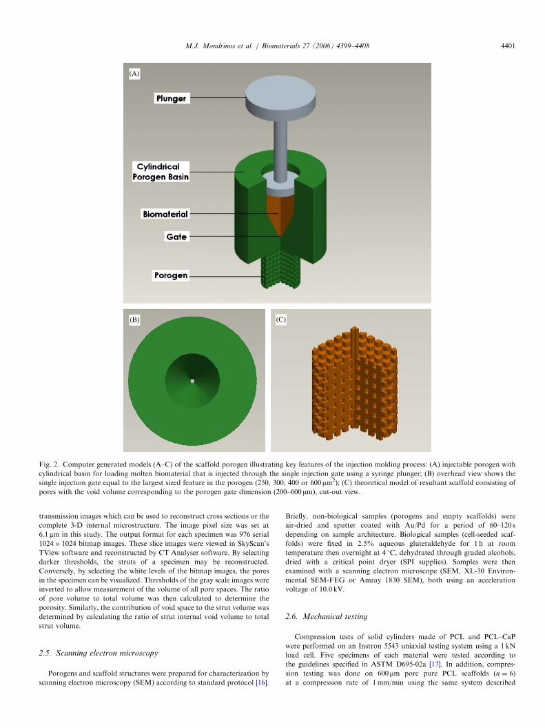
The Pro/EngineerTM-designed injectable porogen model with 100%
interconnectivity is shown in Fig. 2. Each void of the square scaffold is in
the shape of a cube and is separated from adjacent voids by struts on four
of its sides. Scaffold porogens were designed with discrete pore sizes
varying between 200 and 600mm. In order to empirically determine the
minimum porogen basin wall thickness and maximum biomaterial
injection temperature for which thermoplastic porogens would consis-
tently maintain structural integrity, simple destructive testing was
conducted. Based on these preliminary experiments, a 3.18mm wall
thickness and a biomaterial injection temperature of 75 1C were selected.
In order to minimize air entrapment and weld line formation, the
porogen was designed such that molten biomaterial would flow into the
cavities of the porogen through a single gate or injection port (Fig. 2B).
The dimensions of the port’s cross-section were equal to the pore size of
the particular scaffold being injected (e.g. the gate was 600� 600mm2 for
600mm-wide pores), except for the fabrication of 200mm pore scaffolds,
which required an opening of 250� 250mm2. Therefore, a transition
region was needed to go from a relatively large basin where molten
material could be deposited down to the gate dimension corresponding to
the desired pore size of the scaffold being fabricated (Fig. 2B). The interior
diameter of the basin was designed such that the plunger of a standard
plastic 1ml syringe could be used to force the molten biomaterial into the
cavities of the porogen (Fig. 2A). A cutout view model of the desired
resultant scaffold geometry following porogen injection and subsequent
removal is shown in Fig. 2C.
2.3. Fabrication of scaffolds
Following fabrication of structured thermoplastic porogens, scaffolds
were generated by injection molding as described below.
PCL Scaffolds: PCL pellets (average molecular weight ¼ 65,000,
Sigma) were melted in an oven (VWR 1410) at 75 1C. Concomitantly,
the porogens were also preheated to 75 1C. Molten PCL was drawn into a
1ml syringe. The flat tip of the syringe was placed into the basin, thus
allowing the plunger of the syringe to advance from the syringe body into
the cylindrical basin of the porogen (Fig. 2A). The syringe was emptied
quickly and the filled porogen was allowed to cool to room temperature.
After solidifying, excess PCL which had extruded out of the openings on
the sides of the porogen and the porogen basin was trimmed.
In order to separate the porogen from the scaffold structure after
biomaterial solidification, the filled porogens were immersed into 99%
ethanol (Fisher) in a 10ml test tube. The tubes were shaken vigorously and
the solvent replaced every 15–20 s, until all (colored) porogen material was
dissolved, as evaluated by the colorless appearance of the solvent. Using
this method, most of the porogen material was removed in o5min, with
soaking for no more than 1 h to remove residual thermoplastic from the
scaffold center. After porogen removal, the scaffolds were then allowed to
air-dry at room temperature and stored dry as long as needed prior to cell
culture and mechanical testing.
PCL–CaP composite scaffolds: PCL–CaP composite scaffolds were
fabricated in the same fashion as the PCL scaffolds, after first preparing
the mixture of PCL and CaP. For that, dry PCL pellets and CaP powders
were weighed and mixed at the desired ratios in an aluminum specimen
dish. After melting the mixture at 75 1C, the PCL–CaP was homogenized
using an ultrasonic probe, and reheated as necessary; total mixing time
was approximately 30min. Scaffolds were made with ratios (w/w) of 90%
PCL to 10% CaP and 80% PCL to 20% CaP.
2.4. Microcomputed tomography
Nine scaffolds with 600mm pores made of pure PCL, 90:10 and 80:20
PCL–CaP (n ¼ 3 for each material) were fabricated and scanned using a
SkyScan 1072 Microtomograph (mCT) scanner (Micro Photonics). This is
a compact, desktop X-ray system for non-destructive 3-D microscopy with
5mm resolution and 2mm detectability operating at 100 kV, yielding
ARTICLE IN PRESS
Fig. 2. Computer generated models (A–C) of the scaffold porogen illustrating key features of the injection molding process: (A) injectable porogen with
cylindrical basin for loading molten biomaterial that is injected through the single injection gate using a syringe plunger; (B) overhead view shows the
single injection gate equal to the largest sized feature in the porogen (250, 300, 400 or 600mm2); (C) theoretical model of resultant scaffold consisting of
pores with the void volume corresponding to the porogen gate dimension (200–600mm), cut-out view.
M.J. Mondrinos et al. / Biomaterials 27 (2006) 4399–4408 4401
transmission images which can be used to reconstruct cross sections or the
complete 3-D internal microstructure. The image pixel size was set at
6.1 mm in this study. The output format for each specimen was 976 serial
1024� 1024 bitmap images. These slice images were viewed in SkyScan’s
TView software and reconstructed by CT Analyser software. By selecting
darker thresholds, the struts of a specimen may be reconstructed.
Conversely, by selecting the white levels of the bitmap images, the pores
in the specimen can be visualized. Thresholds of the gray scale images were
inverted to allow measurement of the volume of all pore spaces. The ratio
of pore volume to total volume was then calculated to determine the
porosity. Similarly, the contribution of void space to the strut volume was
determined by calculating the ratio of strut internal void volume to total
strut volume.
2.5. Scanning electron microscopy
Porogens and scaffold structures were prepared for characterization by
scanning electron microscopy (SEM) according to standard protocol [16].
Briefly, non-biological samples (porogens and empty scaffolds) were
air-dried and sputter coated with Au/Pd for a period of 60–120 s
depending on sample architecture. Biological samples (cell-seeded scaf-
folds) were fixed in 2.5% aqueous gluteraldehyde for 1 h at room
temperature then overnight at 4 1C, dehydrated through graded alcohols,
dried with a critical point dryer (SPI supplies). Samples were then
examined with a scanning electron microscope (SEM, XL-30 Environ-
mental SEM-FEG or Amray 1830 SEM), both using an acceleration
voltage of 10.0 kV.
2.6. Mechanical testing
Compression tests of solid cylinders made of PCL and PCL–CaP
were performed on an Instron 5543 uniaxial testing system using a 1 kN
load cell. Five specimens of each material were tested according to
the guidelines specified in ASTM D695-02a [17]. In addition, compres-
sion testing was done on 600mm pore pure PCL scaffolds (n ¼ 6)
at a compression rate of 1mm/min using the same system described
ARTICLE IN PRESSM.J. Mondrinos et al. / Biomaterials 27 (2006) 4399–44084402
above with a 100N load cell. Effective stress was computed based on
the macroscopic scaffold cross-sectional area. The ultimate compres-
sive strength (UCS) as well as the compression modulus (CM) was
calculated from the effective stress–strain diagrams, as previously
described [17].
2.7. Cell culture
The cytocompatibility of the scaffolds was assessed using human
embryonic palatal mesenchymal (HEPM) cells (American Type Culture
Collection, ATCC, CRL-1486). These cells are routinely maintained in
Eagles’ minimum essential medium (MEM) with Earles’ salts supplemen-
ted with 10% fetal bovine serum (Hyclone), 2.0mM L-glutamine, 1.0mM
sodium pyruvate, 0.1mM non-essential amino acids, and 1.5 g/l sodium
bicarbonate at 37 1C in a 5% CO2 incubator [16].
For cell culture studies, the scaffolds were sterilized with 70% ethanol
for 1 h at room temperature, and washed 3� 5min with sterile phosphate
buffered saline (PBS). The scaffolds were then incubated with a mixture of
30mg/ml collagen type I (BD Biosciences) and MatrigelTM (BD
Biosciences, diluted 1:30) in MEM for 1 h at 37 1C to facilitate
extracellular matrix protein adsorption and enhanced cellular attachment.
Scaffolds were then seeded with a suspension of 1 million HEPM cells/ml
overnight on an orbital shaker (Belly Dancer, Stovall). Following seeding,
scaffolds were transferred to 24-well plates, allowed to equilibrate for 2 h
in the described cell culture medium and the initial level of cell seeding was
assessed by the Alamar Blue (AB, Biosource) assay [16]. In order to assess
cell proliferation on the various scaffolds the AB assay was performed
again on the same samples at day 4 post-seeding. Subsequently, the
samples were fixed in 10% buffered formalin (Fisher) for 1 h at room
temperature and stored in PBS at 4 1C until cytological staining. For
staining, the samples were washed once more with PBS and incubated with
PBS containing 2mg/ml Hoechst 33258 (Bisbenzimide, Sigma), a nuclear
stain.
2.8. Statistical analysis
All data are presented as means7standard deviation (SD). The number
of samples analyzed is listed for each experiment, except for the cell culture
experiment, where the number of samples for each scaffold was 5.
Statistical significance of Alamar BlueTM measurements was assessed by
one way ANOVA with Tukey-Cramer post-tests for multiple compar-
isons, defining po0.05 as significant. Due to unequal variance, compar-
isons for the compressive testing were performed with one-tailed t-test
followed by the Welch correction for significantly different standard
deviations.
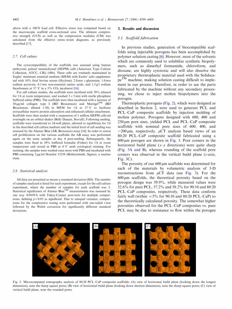
Fig. 3. Microcomputed tomography analysis of 80:20 PCL–CaP composite
dimension), note the sharp square pores; (B) view of horizontal build plane (lo
vertical build plane, note the rounded pores.
3. Results and discussion
3.1. Scaffold fabrication
In previous studies, generation of biocompatible scaf-folds using injectable porogens has been accomplished bypolymer solution casting [6]. However, most of the solventswhich are commonly used to solubilize synthetic biopoly-mers, such as dimethyl formamide, chloroform, anddioxane, are highly cytotoxic and will also dissolve theproprietary thermoplastic material used with the Solidsca-peTM machine, making solution casting difficult to imple-ment in our process. Therefore, in order to use the partsfabricated by the machine without any secondary proces-sing, we chose to inject molten biopolymers into theporogen.Thermoplastic porogens (Fig. 2), which were designed as
described in Section 2, were used to generate PCL andPCL–CaP composite scaffolds by injection molding ofmolten polymer. Porogens designed with 600, 400 and250 mm pore sizes, yielded PCL and PCL–CaP compositescaffolds with nominal pore sizes of 600, 400, and�200 mm, respectively. mCT analysis based views of an80:20 PCL–CaP composite scaffold fabricated using a600 mm porogen are shown in Fig. 3. Pore corners in thehorizontal build plane (x–y directions) were quite sharp(Fig. 3A and B), whereas rounding of the scaffold porecorners was observed in the vertical build plane (z-axis,Fig. 3C).The porosity of our 600 mm scaffolds was determined for
each of the materials by volumetric analysis of 3-Dreconstructions from mCT data (see Fig. 3). For the600 mm scaffolds, the theoretical porosity based on theporogen design was 59.9%, while measured values were52.6% for pure PCL, 57.2% and 58.2% for 90:10 and 80:20PCL–CaP composites, respectively. These data conformfairly well (within o5% for 90:10 and 80:20 PCL–CaP) tothe theoretically calculated porosity. The somewhat higherporosities observed for the PCL–CaP composites vs. purePCL may be due to resistance to flow within the porogen
scaffolds: (A) view of horizontal build plane (looking down the longest
oking down shortest dimension), note the sharp square pores; (C) view of
ARTICLE IN PRESSM.J. Mondrinos et al. / Biomaterials 27 (2006) 4399–4408 4403
caused by the solid CaP particles, whereas the pure PCLmelt flows more freely during injection molding, thus morecompletely filling and compressing the porogen.
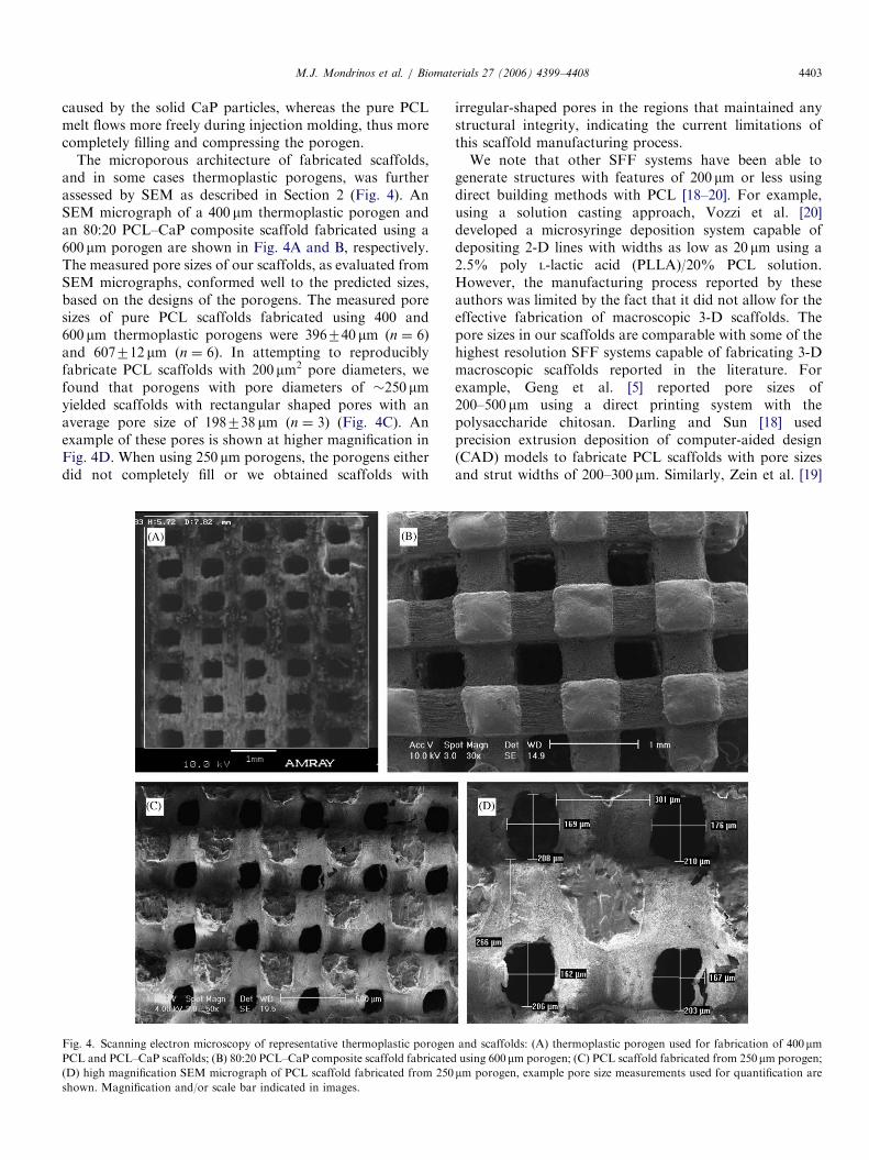
The microporous architecture of fabricated scaffolds,and in some cases thermoplastic porogens, was furtherassessed by SEM as described in Section 2 (Fig. 4). AnSEM micrograph of a 400 mm thermoplastic porogen andan 80:20 PCL–CaP composite scaffold fabricated using a600 mm porogen are shown in Fig. 4A and B, respectively.The measured pore sizes of our scaffolds, as evaluated fromSEM micrographs, conformed well to the predicted sizes,based on the designs of the porogens. The measured poresizes of pure PCL scaffolds fabricated using 400 and600 mm thermoplastic porogens were 396740 mm (n ¼ 6)and 607712 mm (n ¼ 6). In attempting to reproduciblyfabricate PCL scaffolds with 200 mm2 pore diameters, wefound that porogens with pore diameters of �250 mmyielded scaffolds with rectangular shaped pores with anaverage pore size of 198738 mm (n ¼ 3) (Fig. 4C). Anexample of these pores is shown at higher magnification inFig. 4D. When using 250 mm porogens, the porogens eitherdid not completely fill or we obtained scaffolds with
Fig. 4. Scanning electron microscopy of representative thermoplastic porogen
PCL and PCL–CaP scaffolds; (B) 80:20 PCL–CaP composite scaffold fabricated
(D) high magnification SEM micrograph of PCL scaffold fabricated from 250
shown. Magnification and/or scale bar indicated in images.
irregular-shaped pores in the regions that maintained anystructural integrity, indicating the current limitations ofthis scaffold manufacturing process.We note that other SFF systems have been able to
generate structures with features of 200 mm or less usingdirect building methods with PCL [18–20]. For example,using a solution casting approach, Vozzi et al. [20]developed a microsyringe deposition system capable ofdepositing 2-D lines with widths as low as 20 mm using a2.5% poly L-lactic acid (PLLA)/20% PCL solution.However, the manufacturing process reported by theseauthors was limited by the fact that it did not allow for theeffective fabrication of macroscopic 3-D scaffolds. Thepore sizes in our scaffolds are comparable with some of thehighest resolution SFF systems capable of fabricating 3-Dmacroscopic scaffolds reported in the literature. Forexample, Geng et al. [5] reported pore sizes of200–500 mm using a direct printing system with thepolysaccharide chitosan. Darling and Sun [18] usedprecision extrusion deposition of computer-aided design(CAD) models to fabricate PCL scaffolds with pore sizesand strut widths of 200–300 mm. Similarly, Zein et al. [19]
and scaffolds: (A) thermoplastic porogen used for fabrication of 400mmusing 600 mm porogen; (C) PCL scaffold fabricated from 250mm porogen;
mm porogen, example pore size measurements used for quantification are
ARTICLE IN PRESS
500
400
300
200
100
0
CM
(M
p a
)
35
30
20
15
10
5
25
0
UC
S (
MP
a)
100% PCL
90% PCL10 % CaP
80 % PCL20 % CaP
100% PCL
90% PCL10 % CaP
80 % PCL20 % CaP
Material
Material
(A)
(B)
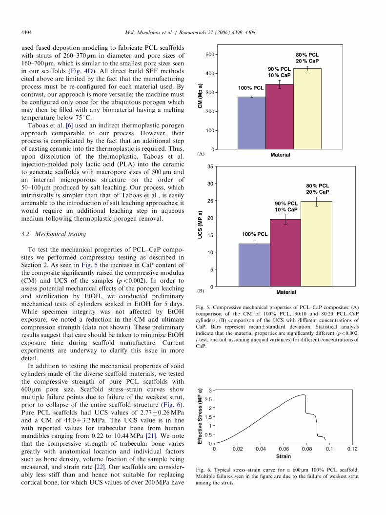
Fig. 5. Compressive mechanical properties of PCL–CaP composites: (A)
comparison of the CM of 100% PCL, 90:10 and 80:20 PCL–CaP
cylinders; (B) comparison of the UCS with different concentrations of
CaP. Bars represent mean7standard deviation. Statistical analysis
indicate that the material properties are significantly different (po0.002,
t-test, one-tail: assuming unequal variances) for different concentrations of
CaP.
3
2.5
2
1.5
1
0.5
00 0.02 0.04 0.06 0.10.08 0.12
Strain
Eff
ecti
ve S
tres
s (M
P a
)
Fig. 6. Typical stress–strain curve for a 600mm 100% PCL scaffold.
Multiple failures seen in the figure are due to the failure of weakest strut
among the struts.
M.J. Mondrinos et al. / Biomaterials 27 (2006) 4399–44084404
used fused depostion modeling to fabricate PCL scaffoldswith struts of 260–370 mm in diameter and pore sizes of160–700 mm, which is similar to the smallest pore sizes seenin our scaffolds (Fig. 4D). All direct build SFF methodscited above are limited by the fact that the manufacturingprocess must be re-configured for each material used. Bycontrast, our approach is more versatile; the machine mustbe configured only once for the ubiquitous porogen whichmay then be filled with any biomaterial having a meltingtemperature below 75 1C.
Taboas et al. [6] used an indirect thermoplastic porogenapproach comparable to our process. However, theirprocess is complicated by the fact that an additional stepof casting ceramic into the thermoplastic is required. Thus,upon dissolution of the thermoplastic, Taboas et al.injection-molded poly lactic acid (PLA) into the ceramicto generate scaffolds with macropore sizes of 500 mm andan internal microporous structure on the order of50–100 mm produced by salt leaching. Our process, whichintrinsically is simpler than that of Taboas et al., is easilyamenable to the introduction of salt leaching approaches; itwould require an additional leaching step in aqueousmedium following thermoplastic porogen removal.
3.2. Mechanical testing
To test the mechanical properties of PCL–CaP compo-sites we performed compression testing as described inSection 2. As seen in Fig. 5 the increase in CaP content ofthe composite significantly raised the compressive modulus(CM) and UCS of the samples (po0.002). In order toassess potential mechanical effects of the porogen leachingand sterilization by EtOH, we conducted preliminarymechanical tests of cylinders soaked in EtOH for 5 days.While specimen integrity was not affected by EtOHexposure, we noted a reduction in the CM and ultimatecompression strength (data not shown). These preliminaryresults suggest that care should be taken to minimize EtOHexposure time during scaffold manufacture. Currentexperiments are underway to clarify this issue in moredetail.
In addition to testing the mechanical properties of solidcylinders made of the diverse scaffold materials, we testedthe compressive strength of pure PCL scaffolds with600 mm pore size. Scaffold stress–strain curves showmultiple failure points due to failure of the weakest strut,prior to collapse of the entire scaffold structure (Fig. 6).Pure PCL scaffolds had UCS values of 2.7770.26MPaand a CM of 44.073.2MPa. The UCS value is in linewith reported values for trabecular bone from humanmandibles ranging from 0.22 to 10.44MPa [21]. We notethat the compressive strength of trabecular bone variesgreatly with anatomical location and individual factorssuch as bone density, volume fraction of the sample beingmeasured, and strain rate [22]. Our scaffolds are consider-ably less stiff than and hence not suitable for replacingcortical bone, for which UCS values of over 200MPa have
ARTICLE IN PRESSM.J. Mondrinos et al. / Biomaterials 27 (2006) 4399–4408 4405
been reported [22]. The small standard deviation (o10%coefficient of variation) for CM and UCS of the solidcylinders as well as 100% PCL scaffolds demonstrates thereproducibility of the mechanical properties achieved usingthis process.
An important issue related to measured mechanicalproperties of our scaffolds is the presence of voids in thestruts resulting from the injection molding process.Microcomputed tomography (mCT) analysis indicatedthat for pure PCL scaffolds only 0.06% of the strutvolume was contributed by voids, whereas the value roseto 0.77% in the case of 80:20 PCL–CaP scaffolds,presumably due to mixing artifacts in the slurry-like,particle-containing polymer melt. We therefore concludethat the mechanical properties of our scaffolds are notadversely affected by inclusion of excessive voids. Themechanical test results can be compared to scaffoldmechanical properties reported by others for PCL scaffoldsof similar porosity (Table 1). CM was slightly higher thanHutmacher et al. [23], in the range reported by Zein et al.[19], and slightly lower than reported by Williams et al. [7].UCS is essentially equal to 0.2% offset yield stress in ourexperiments, due to the brittle failure mode of mostsamples. The mean UCS of our scaffolds was at the highend of the reported range for PCL scaffold yield stress inthe literature [7,19,23].
3.3. Cell-biomaterial interactions
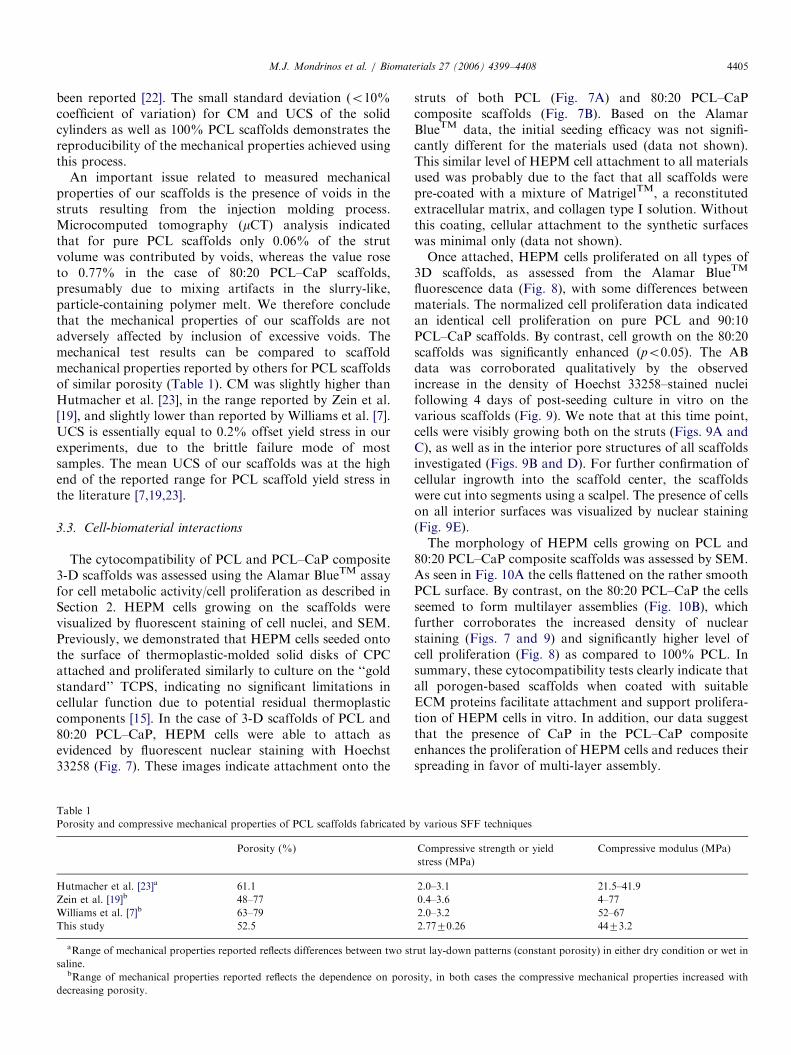
The cytocompatibility of PCL and PCL–CaP composite3-D scaffolds was assessed using the Alamar BlueTM assayfor cell metabolic activity/cell proliferation as described inSection 2. HEPM cells growing on the scaffolds werevisualized by fluorescent staining of cell nuclei, and SEM.Previously, we demonstrated that HEPM cells seeded ontothe surface of thermoplastic-molded solid disks of CPCattached and proliferated similarly to culture on the ‘‘goldstandard’’ TCPS, indicating no significant limitations incellular function due to potential residual thermoplasticcomponents [15]. In the case of 3-D scaffolds of PCL and80:20 PCL–CaP, HEPM cells were able to attach asevidenced by fluorescent nuclear staining with Hoechst33258 (Fig. 7). These images indicate attachment onto the
Table 1
Porosity and compressive mechanical properties of PCL scaffolds fabricated b
Porosity (%)
Hutmacher et al. [23]a 61.1
Zein et al. [19]b 48–77
Williams et al. [7]b 63–79
This study 52.5
aRange of mechanical properties reported reflects differences between two st
saline.bRange of mechanical properties reported reflects the dependence on poro
decreasing porosity.
struts of both PCL (Fig. 7A) and 80:20 PCL–CaPcomposite scaffolds (Fig. 7B). Based on the AlamarBlueTM data, the initial seeding efficacy was not signifi-cantly different for the materials used (data not shown).This similar level of HEPM cell attachment to all materialsused was probably due to the fact that all scaffolds werepre-coated with a mixture of MatrigelTM, a reconstitutedextracellular matrix, and collagen type I solution. Withoutthis coating, cellular attachment to the synthetic surfaceswas minimal only (data not shown).Once attached, HEPM cells proliferated on all types of
3D scaffolds, as assessed from the Alamar BlueTM
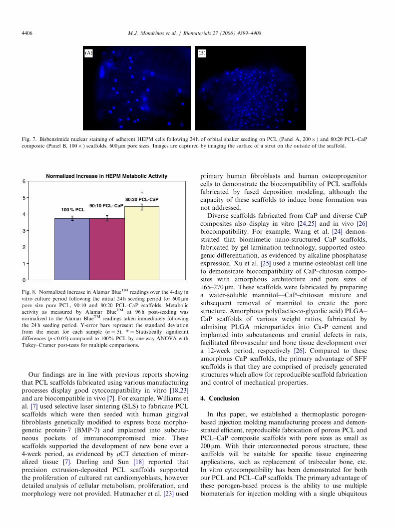
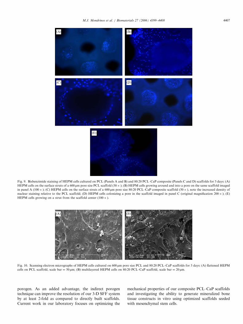
fluorescence data (Fig. 8), with some differences betweenmaterials. The normalized cell proliferation data indicatedan identical cell proliferation on pure PCL and 90:10PCL–CaP scaffolds. By contrast, cell growth on the 80:20scaffolds was significantly enhanced (po0.05). The ABdata was corroborated qualitatively by the observedincrease in the density of Hoechst 33258–stained nucleifollowing 4 days of post-seeding culture in vitro on thevarious scaffolds (Fig. 9). We note that at this time point,cells were visibly growing both on the struts (Figs. 9A andC), as well as in the interior pore structures of all scaffoldsinvestigated (Figs. 9B and D). For further confirmation ofcellular ingrowth into the scaffold center, the scaffoldswere cut into segments using a scalpel. The presence of cellson all interior surfaces was visualized by nuclear staining(Fig. 9E).The morphology of HEPM cells growing on PCL and
80:20 PCL–CaP composite scaffolds was assessed by SEM.As seen in Fig. 10A the cells flattened on the rather smoothPCL surface. By contrast, on the 80:20 PCL–CaP the cellsseemed to form multilayer assemblies (Fig. 10B), whichfurther corroborates the increased density of nuclearstaining (Figs. 7 and 9) and significantly higher level ofcell proliferation (Fig. 8) as compared to 100% PCL. Insummary, these cytocompatibility tests clearly indicate thatall porogen-based scaffolds when coated with suitableECM proteins facilitate attachment and support prolifera-tion of HEPM cells in vitro. In addition, our data suggestthat the presence of CaP in the PCL–CaP compositeenhances the proliferation of HEPM cells and reduces theirspreading in favor of multi-layer assembly.
y various SFF techniques
Compressive strength or yield
stress (MPa)
Compressive modulus (MPa)
2.0–3.1 21.5–41.9
0.4–3.6 4–77
2.0–3.2 52–67
2.7770.26 4473.2
rut lay-down patterns (constant porosity) in either dry condition or wet in
sity, in both cases the compressive mechanical properties increased with
ARTICLE IN PRESS
6
5
4
3
2
1
0
100 % PCL90:10 PCL- CaP
80:20 PCL-CaP *
Normalized Increase in HEPM Metabolic Activity
Fig. 8. Normalized increase in Alamar BlueTM readings over the 4-day in
vitro culture period following the initial 24 h seeding period for 600mmpore size pure PCL, 90:10 and 80:20 PCL–CaP scaffolds. Metabolic
activity as measured by Alamar BlueTM at 96 h post-seeding was
normalized to the Alamar BlueTM readings taken immediately following
the 24 h seeding period. Y-error bars represent the standard deviation
from the mean for each sample (n ¼ 5). * ¼ Statistically significant
differences (po0.05) compared to 100% PCL by one-way ANOVA with
Tukey–Cramer post-tests for multiple comparisons.
Fig. 7. Bisbenzimide nuclear staining of adherent HEPM cells following 24 h of orbital shaker seeding on PCL (Panel A, 200� ) and 80:20 PCL–CaP
composite (Panel B, 100� ) scaffolds, 600mm pore sizes. Images are captured by imaging the surface of a strut on the outside of the scaffold.
M.J. Mondrinos et al. / Biomaterials 27 (2006) 4399–44084406
Our findings are in line with previous reports showingthat PCL scaffolds fabricated using various manufacturingprocesses display good cytocompatibility in vitro [18,23]and are biocompatible in vivo [7]. For example, Williams etal. [7] used selective laser sintering (SLS) to fabricate PCLscaffolds which were then seeded with human gingivalfibroblasts genetically modified to express bone morpho-genetic protein-7 (BMP-7) and implanted into subcuta-neous pockets of immunocompromised mice. Thesescaffolds supported the development of new bone over a4-week period, as evidenced by mCT detection of miner-alized tissue [7]. Darling and Sun [18] reported thatprecision extrusion-deposited PCL scaffolds supportedthe proliferation of cultured rat cardiomyoblasts, howeverdetailed analysis of cellular metabolism, proliferation, andmorphology were not provided. Hutmacher et al. [23] used
primary human fibroblasts and human osteoprogenitorcells to demonstrate the biocompatibility of PCL scaffoldsfabricated by fused deposition modeling, although thecapacity of these scaffolds to induce bone formation wasnot addressed.Diverse scaffolds fabricated from CaP and diverse CaP
composites also display in vitro [24,25] and in vivo [26]biocompatibility. For example, Wang et al. [24] demon-strated that biomimetic nano-structured CaP scaffolds,fabricated by gel lamination technology, supported osteo-genic differentiation, as evidenced by alkaline phosphataseexpression. Xu et al. [25] used a murine osteoblast cell lineto demonstrate biocompatibility of CaP–chitosan compo-sites with amorphous architecture and pore sizes of165–270 mm. These scaffolds were fabricated by preparinga water-soluble mannitol—CaP–chitosan mixture andsubsequent removal of mannitol to create the porestructure. Amorphous poly(lactic-co-glycolic acid) PLGA–CaP scaffolds of various weight ratios, fabricated byadmixing PLGA microparticles into Ca-P cement andimplanted into subcutaneous and cranial defects in rats,facilitated fibrovascular and bone tissue development overa 12-week period, respectively [26]. Compared to theseamorphous CaP scaffolds, the primary advantage of SFFscaffolds is that they are comprised of precisely generatedstructures which allow for reproducible scaffold fabricationand control of mechanical properties.
4. Conclusion
In this paper, we established a thermoplastic porogen-based injection molding manufacturing process and demon-strated efficient, reproducible fabrication of porous PCL andPCL–CaP composite scaffolds with pore sizes as small as200mm. With their interconnected porous structure, thesescaffolds will be suitable for specific tissue engineeringapplications, such as replacement of trabecular bone, etc.In vitro cytocompatibility has been demonstrated for bothour PCL and PCL–CaP scaffolds. The primary advantage ofthese porogen-based process is the ability to use multiplebiomaterials for injection molding with a single ubiquitous
ARTICLE IN PRESS
Fig. 10. Scanning electron micrographs of HEPM cells cultured on 600 mm pore size PCL and 80:20 PCL–CaP scaffolds for 5 days: (A) flattened HEPM
cells on PCL scaffold, scale bar ¼ 50 mm; (B) multilayered HEPM cells on 80:20 PCL–CaP scaffold, scale bar ¼ 20 mm.
Fig. 9. Bisbenzimide staining of HEPM cells cultured on PCL (Panels A and B) and 80:20 PCL–CaP composite (Panels C and D) scaffolds for 5 days: (A)
HEPM cells on the surface struts of a 600mm pore size PCL scaffold (50� ); (B) HEPM cells growing around and into a pore on the same scaffold imaged
in panel A (100� ); (C) HEPM cells on the surface struts of a 600mm pore size 80:20 PCL–CaP composite scaffold (50� ), note the increased density of
nuclear staining relative to the PCL scaffold; (D) HEPM cells colonizing a pore in the scaffold imaged in panel C (original magnification 200� ); (E)
HEPM cells growing on a strut from the scaffold center (100� ).
M.J. Mondrinos et al. / Biomaterials 27 (2006) 4399–4408 4407
porogen. As an added advantage, the indirect porogentechnique can improve the resolution of our 3-D SFF systemby at least 2-fold as compared to directly built scaffolds.Current work in our laboratory focuses on optimizing the
mechanical properties of our composite PCL–CaP scaffoldsand investigating the ability to generate mineralized bonetissue constructs in vitro using optimized scaffolds seededwith mesenchymal stem cells.
ARTICLE IN PRESSM.J. Mondrinos et al. / Biomaterials 27 (2006) 4399–44084408
Acknowledgments
We gratefully acknowledge the support by the NationalScience Foundation (NSF, DMI-0300405) and thank theMachine Shop of Drexel University for helping us to makesome machine parts. We thank Dr. Mengyan Li for herassistance with SEM.
References
[1] Langer R, Vacanti J. Tissue engineering. Science 1993;260:920–6.
[2] Mistry AS, Mikos AG. Tissue engineering strategies for bone
regeneration. Adv Biochem Eng Biotechnol 2005;94:1–22.
[3] Thomson RC, Mikos AG, Beahm E, Lemon JC, Satterfield WC,
Aufdemorte TB, et al. Guided tissue fabrication from periosteum
using preformed biodegradable polymer scaffolds. Biomaterials
1999;20(21):2007–18.
[4] Ohgushi H, Miyake J, Tateishi T. Mesenchymal stem cells and
bioceramics: strategies to regenerate the skeleton. Novartis Found
Symp 2003;249:118–27 (discussion 127–32, 170–4, 239–41).
[5] Geng L, Feng W, Hutmacher DW, Wong YS, Loh HT, Fuh JYH.
Direct writing of chitosan scaffolds using a robotic system. Rapid
Prototyping J 2005;11(2):90–7.
[6] Taboas JM,Maddox RD, Krebsbach PH, Hollister SJ. Indirect solid free
form fabrication of local and global porous, biomimetic and composite
3D polymer-ceramic scaffolds. Biomaterials 2003;24(1):181–94.
[7] Williams JM, Adewunmi A, Schek RM, Flanagan CL, Krebsbach
PH, Feinberg SE, et al. Bone tissue engineering using polycapro-
lactone scaffolds fabricated via selective laser sintering. Biomaterials
2005;26(23):4817–27.
[8] Hollister SJ, Maddox RD, Taboas JM. Optimal design and
fabrication of scaffolds to mimic tissue properties and satisfy
biological constraints. Biomaterials 2002;23(20):4095–103.
[9] Shin M, Yoshimoto H, Vacanti JP. In vivo bone tissue engineering
using mesenchymal stem cells on a novel electrospun nanofibrous
scaffold. Tissue Eng 2004;10(1–2):33–41.
[10] Rohner D, Hutmacher DW, Cheng TK, Oberholzer M, Hammer M.
In vivo efficacy of bone-marrow-coated polycaprolactone scaffolds
for the reconstruction of orbital defects in the pig. J Biomed Mater
Res 2003;66B(2):574–80.
[11] Wilt FH. Developmental biology meets materials science: morpho-
genesis of biomineralized structures. Dev Biol 2005;280(1):15–25.
[12] Ruhe PQ, Hedberg EL, Padron NT, Spauwen PH, Jansen JA, Mikos
AG. rhBMP-2 release from injectable poly(DL-lactic-co-glycolic acid)/
calcium-phosphate cement composites. J Bone Joint Surg Am
2003;85-A(Suppl 3):75–81.
[13] Xu HH, Quinn JB, Takagi S, Chow LC. Synergistic reinforcement of
in situ hardening calcium phosphate composite scaffold for bone
tissue engineering. Biomaterials 2004;25(6):1029–37.
[14] Barralet JE, Grover L, Gaunt T, Wright AJ, Gibson IR. Preparation
of macroporous calcium phosphate cement tissue engineering
scaffold. Biomaterials 2002;23(15):3063–72.
[15] Lu L, Dembzynski RS, Mondrinos MJ, Wootton D, Lelkes PI, Zhou
J. Manufacturing system development for fabrication of bone
scaffolds. In: Proceeding of ASME IMECE 2005, International
mechanical engineering congress and exposition, Orlando, Florida,
November 5–11, 2005.
[16] Li M, Mondrinos MJ, Gandhi MR, Ko FK, Weiss AS, Lelkes PI.
Electrospun protein fibers as matrices for tissue engineering.
Biomaterials 2005;26(30):5999–6008.
[17] Wang F, Shor L, Darling A, Khalil S, Sun W, Guceri S, et al.
Precision extruding deposition and characterization of cellular poly
e-caprolactone tissue scaffolds. Rapid Prototyping J 2004;10(1):42–9.
[18] Darling AL, Sun W. 3D microtomographic characterization of
precision extruded poly epsilon-caprolactone scaffolds. J Biomed
Mater Res 2004;70B(2):311–7.
[19] Zein I, Hutmacher DW, Tan KC, Teoh SH. Fused deposition
modeling of novel scaffold architectures for tissue engineering
applications. Biomaterials 2002;23(4):1169–85.
[20] Vozzi G, Previti A, De Rossi D, Ahluwalia A. Microsyringe-based
deposition of two-dimensional and three-dimensional polymer
scaffolds with a well-defined geometry for application to tissue
engineering. Tissue Eng 2002;8(6):1089–98.
[21] Misch CE, Qu Z, Bidez MW. Mechanical properties of trabecular
bone in the human mandible: implications for dental implant
treatment planning and surgical placement. J Oral Maxillofac Surg
1999;57(6):700–6 (discussion 706–8).
[22] Carter DR, Hayes WC. Bone compressive strength: the influence of
density and strain rate. Science 1976;194:1174–6.
[23] Hutmacher DW, Schantz T, Zein I, Ng KW, Teoh SH, Tan KC.
Mechanical properties and cell cultural response of polycaprolactone
scaffolds designed and fabricated via fused deposition modeling.
J Biomed Mater Res 2001;55(2):203–16.
[24] Wang T, Tian WD, Liu L, Cheng XZ, Liao YM, Li SW. The study of
cell biocompatibility of new pattern biphasic calcium phosphate
nanocomposite in vitro. Hua Xi Kou Qiang Yi Xue Za Zhi
2005;23(2):106–9.
[25] Xu HH, Simon Jr CG. Fast setting calcium phosphate-chitosan
scaffold: mechanical properties and biocompatibility. Biomaterials
2005;26(12):1337–48.
[26] Ruhe PQ, Hedberg EL, Padron NT, Spauwen PH, Jansen JA, Mikos
AG. Biocompatibility and degradation of poly(DL-lactic-co-glycolic
acid)/calcium phosphate cement composites. J Biomed Mater Res
2005;74(4):533–44.