Ponds- Planning, Design, Construction, Pages 10-36
27
Drainage Area Protection To maintain the required depth and capacity of a pond, the inflow must be reasonably free of silt from an eroding watershed. The best protection is adequate erosion control on the contributing drainage area. Land under permanent cover of trees or grasses is the most desirable drainage area (fig. 12). If such land is not available, use cultivated areas protected by conservation practices such as terracing, contour tillage, stripcropping, or conservation cropping systems. If an eroding or inadequately protected watershed must be used to supply pond water, delay pond construction until conservation practices are established. In any event, protection of the drainage area should be started as soon as you decide to build a pond. Pond Capacity Estimate pond capacity to be sure that enough water is stored in the pond to satisfy the intended use requirements. A simple method follows: Establish the normal pond-full water elevation and stake the waterline at this point. Measure the width of the valley at this elevation at regular intervals and use these measurements to compute the pond-full surface area in acres. Multiply the surface area by 0.4 times the maximum water depth in feet measured at the dam. For example, a pond with a surface area of 3.2 acres and a depth of 12.5 feet at the dam has an approximate capacity of 16 acre feet (0.4 x 3.2 x 12.5 = 16 acre-feet) (1 acre-foot = 325,851 gallons). Landscape Evaluation Alternative pond sites should be evaluated for potential visibility and compatibility with surrounding landscape characteristics and use patterns (fig. 13). Identify major viewpoints (points from which the site is viewed) and draw the important sight lines with cross sections, where needed, to determine visibility. If feasible, locate the pond so that the major sight line crosses the longest dimension of water surface. The pond should be placed so that a viewer will see the water first before noticing the dam, pipe inlet, or spillway. Often, minor changes in the dam alignment and spillway location can shift these elements out of view and reduce their prominence If possible, locate your pond so that some existing trees and shrubs remain along part of the shoreline. The vegetation will add interest by casting reflections on the water, will provide shade on summer days, and will help blend the pond into the surrounding landscape. Often it is possible to locate or design a pond so that an island can be created for recreation, wildlife habitat, or visual interest. In addition to the more typical farm and residential sites, ponds can be located in landscapes of poor quality to rehabilitate abandoned road borrow areas, dumping sites, abandoned rural mines, and other low production areas. Figure 12. Land with permanent vegetation makes the most desirable drainage area. 10
Transcript of Ponds- Planning, Design, Construction, Pages 10-36

Drainage Area Protection
To maintain the required depth and capacity of apond, the inflow must be reasonably free of silt from aneroding watershed. The best protection is adequateerosion control on the contributing drainage area. Landunder permanent cover of trees or grasses is the mostdesirable drainage area (fig. 12). If such land is notavailable, use cultivated areas protected byconservation practices such as terracing, contourtillage, stripcropping, or conservation croppingsystems.
If an eroding or inadequately protected watershedmust be used to supply pond water, delay pondconstruction until conservation practices areestablished. In any event, protection of the drainagearea should be started as soon as you decide to builda pond.
Pond Capacity
Estimate pond capacity to be sure that enoughwater is stored in the pond to satisfy the intended userequirements. A simple method follows:
Establish the normal pond-full water elevation andstake the waterline at this point. Measure the width ofthe valley at this elevation at regular intervals and usethese measurements to compute the pond-full surfacearea in acres. Multiply the surface area by 0.4 times themaximum water depth in feet measured at the dam.For example, a pond with a surface area of 3.2 acresand a depth of 12.5 feet at the dam has anapproximate capacity of 16 acre
feet (0.4 x 3.2 x 12.5 = 16 acre-feet) (1 acre-foot =325,851 gallons).
Landscape Evaluation
Alternative pond sites should be evaluated forpotential visibility and compatibility with surroundinglandscape characteristics and use patterns (fig. 13).Identify major viewpoints (points from which the site isviewed) and draw the important sight lines with crosssections, where needed, to determine visibility. Iffeasible, locate the pond so that the major sight linecrosses the longest dimension of water surface. Thepond should be placed so that a viewer will see thewater first before noticing the dam, pipe inlet, orspillway. Often, minor changes in the dam alignmentand spillway location can shift these elements out ofview and reduce their prominence
If possible, locate your pond so that some existingtrees and shrubs remain along part of the shoreline.The vegetation will add interest by casting reflectionson the water, will provide shade on summer days, andwill help blend the pond into the surroundinglandscape. Often it is possible to locate or design apond so that an island can be created for recreation,wildlife habitat, or visual interest.
In addition to the more typical farm andresidential sites, ponds can be located in landscapesof poor quality to rehabilitate abandoned road borrowareas, dumping sites, abandoned rural mines, andother low production areas.
Figure 12. Land with permanentvegetation makes the mostdesirable drainage area.
10
Fred S. Conte
PDF file created by UC Davis, California Aquaculture, 4/00; JSC

Estimating Storm Runoff
The amount of precipitation, whether it occurs asrain or snow, is the potential source of water that mayrun off small watersheds. The kind of soil and the typeof vegetation affect the amount of water that runs off.Terraces and diversions, along with steepness andshape of a watershed, affect the rate at which waterruns off.
A spillway is provided to bypass surface runoffafter the pond is filled. Use the following tables andcharts to estimate the peak discharge rates for thespillway. They provide a quick and reliable estimate ofrunoff rates and associated volumes for a range ofstorm rainfall amounts, soil groups, land use, coverconditions, and average watershed slopes. The peakdischarge rates in the charts were computed byautomatic data processing equipment using SCSnational procedures.
Rainfall Amounts and Expected Frequency
Maps showing the amount of rainfall expected ina 24-hour period have been reproduced in figures14-1, 14-2, and 14-3 (pp. 12-14) from the U.S.Weather Bureau Technical Paper 40 (USWP-TP-40),
Rainfall Frequency Atlas of the United States. Morespecific rainfall information for areas west of the 105thmeridian is in the Precipitation Frequency Atlas of theWestern United States (NOAA Atlas 2).
It is impractical to design an ordinary pondspillway to accommodate the peak rate of runoff fromthe most intense rainstorm ever known or anticipated.The spillway for an ordinary farm pond is usuallydesigned to pass the runoff from a 25-year frequencystorm (fig. 14-2). This means a storm with only a4-percent chance of occurring in any year or the sizebeyond which larger storms would not occur more oftenthan an average of once in 25 years. Designing for a50-year storm frequency is recommended for spillwaysfor larger dams. A 10-year storm frequency may beadequate for sizing the spillway in very small ponds.
Hydrologic Groupings of Soils
Soils have been classified in four hydrologicgroups according to infiltration and transmissionrates:
A: These soils have a high infiltration rate.They are chiefly deep, well-drained sands orgravels. They have low runoff potential.
11

12

13

14

B. These soils have a moderate infiltration ratewhen thoroughly wet. They are chiefly moderatelydeep, well-drained soils of moderately fine tomoderately coarse texture.
C. These soils have a slow infiltration ratewhen wet. They are soils with a layer that impedesdownward movement of water and soils ofmoderately fine to fine texture.
D. These soils have a very slow infiltrationrate. They are chiefly clay soils with a high swellingpotential, soils with a permanent high water table,soils with a claypan at or near the surface, andshallow soils over nearly impervious material. Theyhave high runoff potential.
The SCS district conservationist or yourcounty extension agent can help you classify thesoils for a given pond site in one of the fourhydrologic groups.
Runoff Curve Numbers
A numerical runoff rating is shown in table 1 fora range of soil-use-cover complexes. Because thesenumbers relate to a set of curves developed from theSCS runoff equation, they are referred to as curvenumbers in table 2 and on figure 15 (pp. 16-18).Figure 15 is a set of three charts that show the peakrates of discharge by slope for a range of curvenumbers.
The watershed above a farm pond often containsareas represented by different curve numbers. Aweighted curve number can be obtained based on thepercentage of area for each curve number. Forexample, assume that the watershed above a pond ismainly (three-fourths) in good pasture and a soil inhydrologic group B. The remainder is cultivated
Table 2.-Runoff depth in inches
with conservation treatment on a soil in hydrologicgroup C. According to table 1, three-fourths of thewatershed has a 61 curve number and the otherone-fourth a 78 curve number. A weighted curvenumber for the total watershed would be :
3/4 X 61 = 46 (approximately)1/4 X 78 = 20 (approximately)Weighted = 66
Volume of Storm Runoff
Often it is good to know how much water runs offfrom a big storm as well as the rate at which it flows.The volume is also needed to compute the peakdischarge rate.
The figures in table 2 are the depth (in inches) atwhich the storm runoff, if spread evenly, would
Table 1.-Runoff curve numbers
15

Figure 15-1. Peak rates of discharge for small watershedson flat slopes (24-hour, type-11 storm distribution).
16
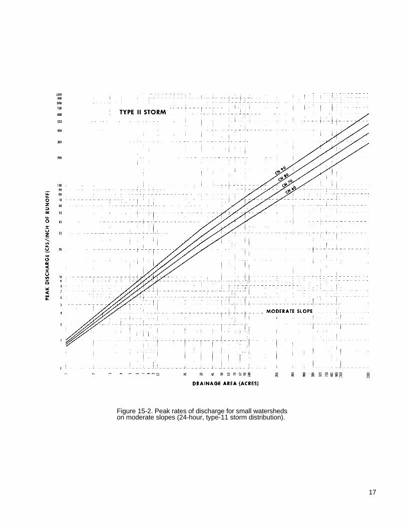
Figure 15-2. Peak rates of discharge for small watershedson moderate slopes (24-hour, type-11 storm distribution).
17

Figure 15-3. Peak rates of discharge for small watershedson steep slopes (24-hour, type-11 storm distribution).
18

inches)
cover the entire watershed. For example, the volumeof runoff from a 3-inch rainfall on a 100-acrewatershed with the weighted curve number of 66would be:
0.55 inch (interpolated between 0.51 and 0.72
100 acres x 0.55 inch = 55 acre-inches
55 acre-inches - 12 = 4.55 acre-feet
55 acre-inches X 27,154 gallons per acre-inch1.5 million gallons (approximately)
Peak Discharge Rate
The slope of the land above the pond affects thepeak discharge rate significantly. The rates in figure 15are for flat, moderate, and steep slopes. Data inpublished soil surveys give the average watershedslope at most locations. Generally the average slopecan be judged closely enough to place the watershedin one of the three slope categories of figure 15. Table3 shows the range in slopes.
The rate at which storm runoff passes through thespillway of a farm pond is measured in cubic feet persecond (cfs). (This can also be expressed as ftl/sec.)The vertical scale of the charts in figure 15 shows thecubic feet of water per inch of runoff that must passthrough the spillway every second. To determine thisrate, first find the chart for the appropriate watershedslope. Then follow the chart along the base at the sizeof the area that drains into the pond. Move vertically tothe curve number. Read the peak discharge rate in cfsper inch of runoff along the vertical scale. The volumeof runoff is obtained by entering table 2 with the24-hour rainfall from figure 14 and the curve number.The peak discharge rate in cfs is the discharge ratefrom figure 15 multiplied by the volume of runoff fromtable 2. These discharge rates are for the intensesummer thunderstorms that are common throughoutmost of the United States.
The maritime climate along the Pacific coast sideof the Sierra Nevada and the Cascade Mountains inCalifornia, Oregon, and Washington has winter rainfallof less intensity. The peak discharge rate for theseareas in about 25 percent of that shown in the chartsof figure 15.
The following example illustrates how to usetables 2 and 3 and figures 14 and 15 to obtain thepeak discharge rate for estimating the capacityneeded in the spillway.
Given (1) a 90-acre watershed in Salem Countyin southern New Jersey; (2) it has moderate water
shed slopes; (3) the soils shown on the Salem Countysoil map are in hydrologic soil group C; and (4) thelandscape is meadow. The spillway should be largeenough to pass the runoff from a 25-year frequencyrainstorm. Figure 14-2 shows that the 24-hour, 25-yearfrequency rainfall is about 6 inches. The runoff curvenumber for meadow and hydrologic soil group C is 71(table 1). In figure 15-2, the moderate slope and curvenumber 71 shows about 50 cfs per inch of runoff for a90-acre drainage area.
According to table 2, for 6 inches of rainfall and acurve number of 71 the volume of runoff is 2.95inches. The peak discharge for construction of thespillway is 50 X 2.95 = 148 cfs.
Engineering Surveys
Once you determine the probable location of thepond, make enough engineering surveys to plan thedam, spillway, and other features. For most ponds thesurveys needed are simple, but if you are not familiarwith the use of surveying instruments you shouldemploy an engineer.
Pond surveys usually consist of a profile of thecenterline of the dam, a profile of the centerline of theearth spillway, and enough measurements to estimatepond capacity. A simple method of estimating pondcapacity is described on page 10. For larger and morecomplex ponds, particularly those used to store waterfor irrigation, you may need a complete topographicsurvey of the entire pond site.
Run a line of profile levels along the centerline ofthe proposed dam and up both sides of the valley wellabove the expected elevation of the top of the damand well beyond the probable location of the earthspillway. The profile should show surface elevations atall significant changes in slope and at intervals of nomore than 100 feet. This line of levels establishes theheight of the dam and the location and elevation of theearth spillway and the trickle tube. It is used tocompute the volume of earth needed to build the dam.
Run a similar line of profile levels along thecenterline of the earth spillway. Start from a point onthe upstream end that is well below the selected
Table 3.-Slopes for peak discharge
Slope category Average sloperange
Pct PctFlat1 0 to 3 1Moderate 3 to 8 4Steep 8 and above 16
1Level to nearlylevel.
19
Actual slope used infigure 15 computations
normal water surface elevation and continue to a pointon the downstream end where water can be safelydischarged without damage to the dam. This lineserves as a basis for determining the slope anddimensions of the spillway.
All surveys made at a pond site should be tied toa reference point called a bench mark. This may be alarge spike driven into a tree, an iron rod driven flushwith the ground, a point on the concrete headwall of aculvert, or any object that will remain undisturbedduring construction of the dam.
Embankment Ponds
Detailed Soils Investigation
Soils in the Ponded Area. Suitability of a pondsite depends on the ability of the soils in the reservoirarea to hold water. The soil should contain a layer ofmaterial that is impervious and thick enough to preventexcessive seepage. Clays and silty clays are excellentfor this purpose; sandy clays are usually satisfactory.Coarse-textured sands and sand-gravel mixtures arehighly pervious and therefore usually unsuitable. Theabsence of a layer of impervious material over part ofthe ponded area does not necessarily mean that youmust abandon the proposed site. You can treat theseparts of the area by one of several methods describedlater in this handbook (p. 46). Any of these methodscan be expensive.
Some limestone areas are especially hazardousas pond sites. There may be crevices, sinks orchannels in the limestone below the soil mantle thatare not visible from the surface. These may empty thepond in a short time. In addition, many soils in theseareas are granular. Since the granules do not
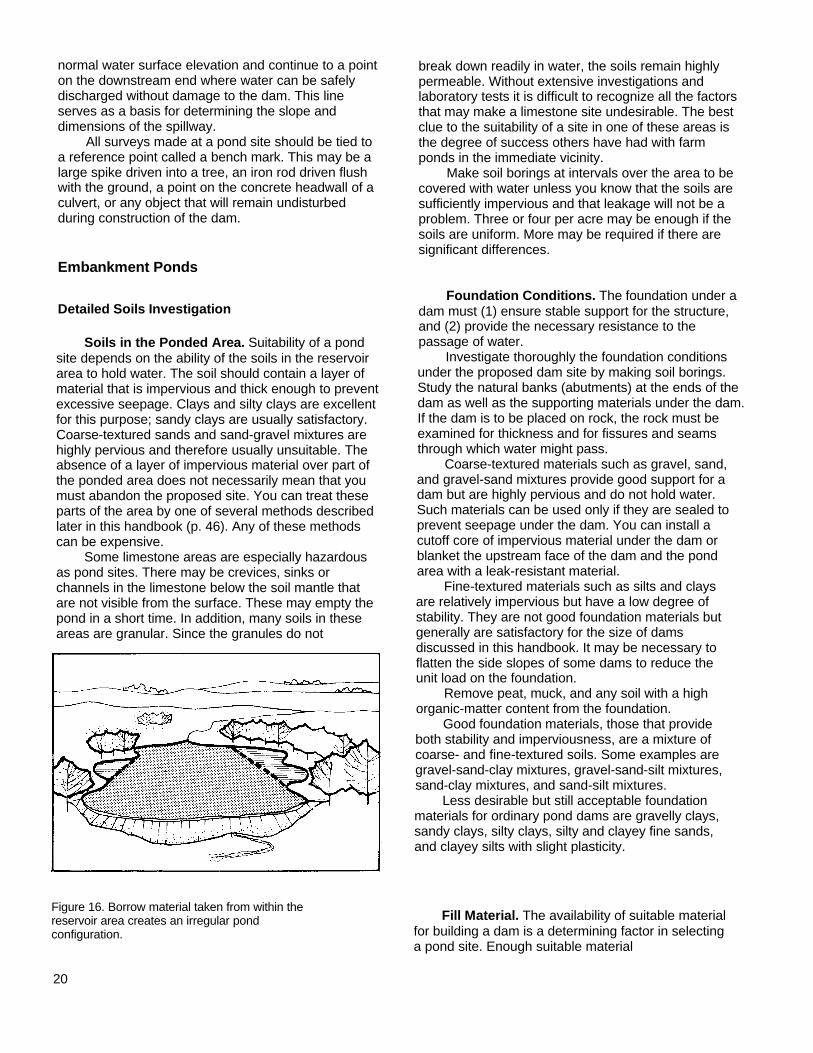
Figure 16. Borrow material taken from within thereservoir area creates an irregular pondconfiguration.
20
break down readily in water, the soils remain highlypermeable. Without extensive investigations andlaboratory tests it is difficult to recognize all the factorsthat may make a limestone site undesirable. The bestclue to the suitability of a site in one of these areas isthe degree of success others have had with farmponds in the immediate vicinity.
Make soil borings at intervals over the area to becovered with water unless you know that the soils aresufficiently impervious and that leakage will not be aproblem. Three or four per acre may be enough if thesoils are uniform. More may be required if there aresignificant differences.
Foundation Conditions. The foundation under adam must (1) ensure stable support for the structure,and (2) provide the necessary resistance to thepassage of water.
Investigate thoroughly the foundation conditionsunder the proposed dam site by making soil borings.Study the natural banks (abutments) at the ends of thedam as well as the supporting materials under the dam.If the dam is to be placed on rock, the rock must beexamined for thickness and for fissures and seamsthrough which water might pass.
Coarse-textured materials such as gravel, sand,and gravel-sand mixtures provide good support for adam but are highly pervious and do not hold water.Such materials can be used only if they are sealed toprevent seepage under the dam. You can install acutoff core of impervious material under the dam orblanket the upstream face of the dam and the pondarea with a leak-resistant material.
Fine-textured materials such as silts and claysare relatively impervious but have a low degree ofstability. They are not good foundation materials butgenerally are satisfactory for the size of damsdiscussed in this handbook. It may be necessary toflatten the side slopes of some dams to reduce theunit load on the foundation.
Remove peat, muck, and any soil with a highorganic-matter content from the foundation.
Good foundation materials, those that provideboth stability and imperviousness, are a mixture ofcoarse- and fine-textured soils. Some examples aregravel-sand-clay mixtures, gravel-sand-silt mixtures,sand-clay mixtures, and sand-silt mixtures.
Less desirable but still acceptable foundationmaterials for ordinary pond dams are gravelly clays,sandy clays, silty clays, silty and clayey fine sands,and clayey silts with slight plasticity.
Fill Material. The availability of suitable materialfor building a dam is a determining factor in selectinga pond site. Enough suitable material
should be located close to the site so that placementcosts are not excessive. If fill material can be takenfrom the reservoir area, the surrounding landscape willbe left undisturbed and borrow areas will not be visibleafter the pond has been filled (fig. 16).
Materials selected must have enough strength forthe dam to remain stable and be tight enough, whenproperly compacted, to prevent excessive or harmfulpercolation of water through the dam. Soils describedas acceptable for foundation material are usuallyacceptable for fill material, except for organic silts andclays.
The best material for an earthfill contains particlesranging from small gravel or coarse sand to fine sandand clay in the desired proportions. This materialshould contain about 20 percent by weight of clayparticles. Though satisfactory earthfills can be builtfrom soils that vary from the ideal, the greater thevariance, the more precautions needed.
Soils containing a high percentage of gravel orcoarse sand are pervious and can allow rapid seepagethrough the dam. When using these soils, place a coreof clay material in the center of the fill and flatten theside slopes to keep the line of seepage from emergingon the downstream slope.
Fill material that has a high clay content swellswhen wet and shrinks when dry. The shrinkage mayopen dangerous cracks. For soils consisting mostly ofsilt, such as the loess areas of western Iowa and alongthe Mississippi River in Arkansas, Mississippi, andTennessee, the right degree of moisture must bemaintained during construction for thoroughcompaction.
To estimate the proportion of sand, silt, and clay ina sample of fill material, first obtain a large bottle withstraight sides. Then take a representative sample ofthe fill material and remove any gravel by passing thematerial through a 1/4-inch sieve or screen. Fill thebottle to about one-third with the sample material andfinish filling with water. Shake the bottle vigorously forseveral minutes and then allow the soil material tosettle for about 24 hours. The coarse material (sand)settles to the bottom first and finer material (clay)settles last. Estimate the proportion of sand, silt, andclay by measuring the thickness of the different layerswith a ruler.
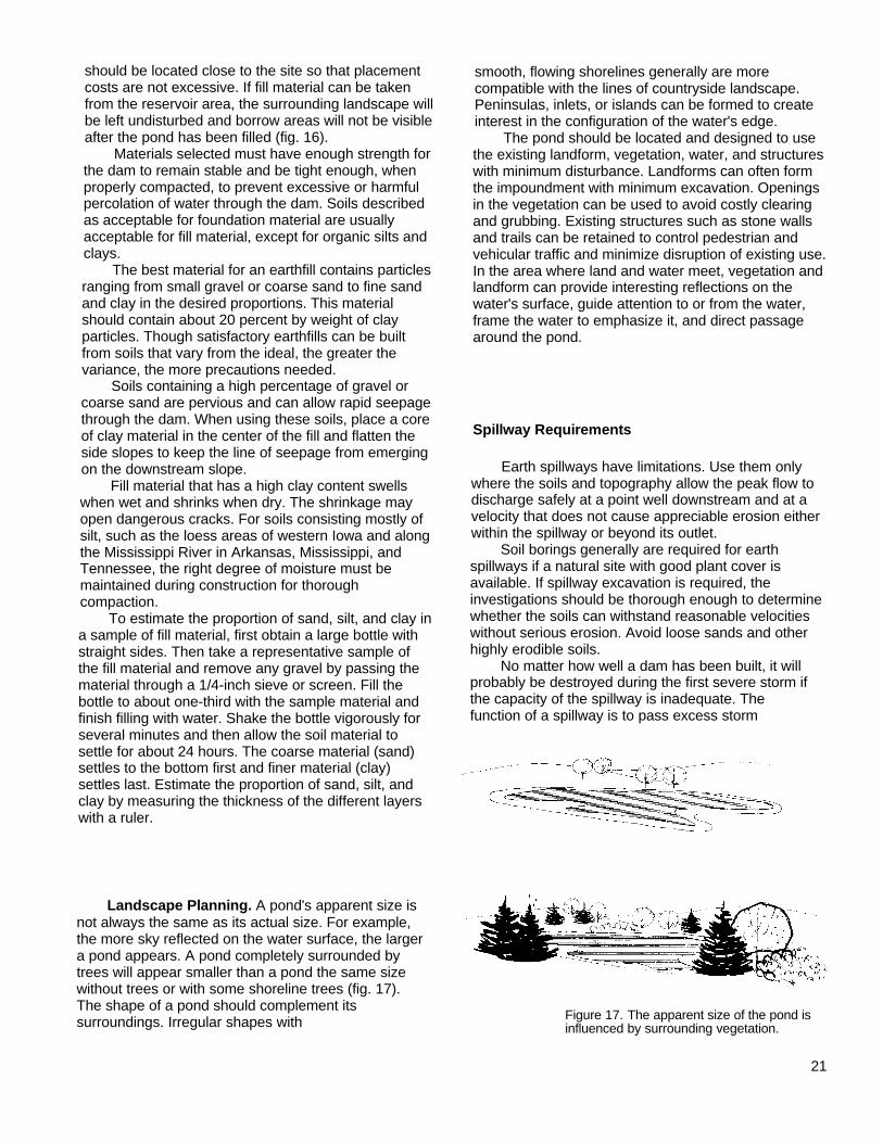
Landscape Planning. A pond's apparent size isnot always the same as its actual size. For example,the more sky reflected on the water surface, the largera pond appears. A pond completely surrounded bytrees will appear smaller than a pond the same sizewithout trees or with some shoreline trees (fig. 17).The shape of a pond should complement itssurroundings. Irregular shapes with
smooth, flowing shorelines generally are morecompatible with the lines of countryside landscape.Peninsulas, inlets, or islands can be formed to createinterest in the configuration of the water's edge.
The pond should be located and designed to usethe existing landform, vegetation, water, and structureswith minimum disturbance. Landforms can often formthe impoundment with minimum excavation. Openingsin the vegetation can be used to avoid costly clearingand grubbing. Existing structures such as stone wallsand trails can be retained to control pedestrian andvehicular traffic and minimize disruption of existing use.In the area where land and water meet, vegetation andlandform can provide interesting reflections on thewater's surface, guide attention to or from the water,frame the water to emphasize it, and direct passagearound the pond.
Spillway Requirements
Earth spillways have limitations. Use them onlywhere the soils and topography allow the peak flow todischarge safely at a point well downstream and at avelocity that does not cause appreciable erosion eitherwithin the spillway or beyond its outlet.
Soil borings generally are required for earthspillways if a natural site with good plant cover isavailable. If spillway excavation is required, theinvestigations should be thorough enough to determinewhether the soils can withstand reasonable velocitieswithout serious erosion. Avoid loose sands and otherhighly erodible soils.
No matter how well a dam has been built, it willprobably be destroyed during the first severe storm ifthe capacity of the spillway is inadequate. Thefunction of a spillway is to pass excess storm
Figure 17. The apparent size of the pond isinfluenced by surrounding vegetation.
21

Table 4.-Minimum spillway design storm
EffectiveDrainage height Minimum
area of dam1 Storage Frequency duration
(acre) (ft) (acre-ft) (yr) (hr)
20 or less ............... 20 or less Less than 50 10 2420 or less ............... More than 20 Less than 50 25 24More than 20 ......... 20 or less Less than 50 25 24
1The effective height of the dam is the difference in elevation betweenthe emergency spillway crest and the lowest point in the cross sectiontaken along the centerline of the dam.
22
Minimum design

runoff around the dam so that water in the pond doesnot rise high enough to damage the dam byovertopping. The spillway must also convey the watersafely to the outlet channel below without damagingthe downstream slope of the dam. The properfunctioning of a pond depends on a correctly designedand installed spillway.
Emergency spillways should have the minimumcapacity to discharge the peak flow expected from astorm of the frequency and duration shown in table 4less any reduction creditable to conduit discharge anddetention storage. After the spillway capacityrequirements are calculated, the permissible velocitymust be determined. Table 5 contains therecommended allowable velocity for various types ofcover, degree of erosion resistance, and slope of thechannel. Table 6 gives the retardance factors for theexpected height of the vegetation.
Both natural and excavated earth spillways areused. A natural spillway does not require excavation toprovide enough capacity to conduct the pond outflow toa safe point of release (fig. 18). The requirementsdiscussed later for excavated spillways do not apply tonatural spillways, but the capacity must be adequate.
With the required discharge capacity (Q), theend slope of the embankment (Z1), and the slope ofthe natural ground (Z2) known, the maximum depth ofwater above the level portion (Hp) can be obtained
7:
Given:
Solution:
from table 7 (p. 24). The depth is added to theelevation of the spillway crest to determine themaximum elevation to which water will rise in thereservoir. The following example shows how to usetable
Q = 86 ft3/s (cubic feet per second)
Vegetation: good stand of bermudagrass
Height: 6 to 10 inches
Slope of natural ground: 1.0 percent
From table 6, determine a retardance of C.
From table 7, under natural ground slope 1percent and retardance C column, find Q = 86 ft3/sat Hp = 1.3 ft and V = 2.7
If the freeboard is 1.0 foot, the top of the damshould be constructed 2.3 feet higher than the spillwaycrest. The velocity is well below the maximumpermissible velocity of 8 feet per second given in
Figure 18. Plan, profile, and cross section of a natural spillwaywith vegetation.
23
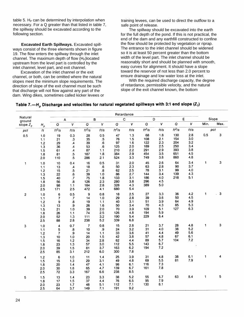
table 5. HP can be determined by interpolation whennecessary. For a Q greater than that listed in table 7,the spillway should be excavated according to thefollowing section.
Excavated Earth Spillways. Excavated spill-ways consist of the three elements shown in figure19. The flow enters the spillway through the inletchannel. The maximum depth of flow (HP)locatedupstream from the level part is controlled by theinlet channel, level part, and exit channel.
Excavation of the inlet channel or the exitchannel, or both, can be omitted where the naturalslopes meet the minimum slope requirements. Thedirection of slope of the exit channel must be suchthat discharge will not flow against any part of thedam. Wing dikes, sometimes called kicker levees or
training levees, can be used to direct the outflow to asafe point of release.
The spillway should be excavated into the earthfor the full depth of the pond. If this is not practical, theend of the dam and any earthfill constructed to confinethe flow should be protected by vegetation or riprap.The entrance to the inlet channel should be widenedso it is at least 50 percent greater than the bottomwidth of the level part. The inlet channel should bereasonably short and should be planned with smooth,easy curves for alignment. It should have a slopetoward the reservoir of not less than 2.0 percent toensure drainage and low water loss at the inlet.
With the required discharge capacity, the degreeof retardance, permissible velocity, and the naturalslope of the exit channel known, the bottom
24

25

width of the level and exit sections and the depth of theflow (HP) can be computed from figures in table 8.Table 8 shows discharge per foot of width. The naturalslope of the exit channel should be altered as little aspossible.
The selection of the degree of retardance for agiven spillway will depend mainly on the height anddensity of the cover chosen (table 6). Generally, theretardance for uncut grass or vegetation is the one touse for capacity determination. Since protection andretardance are lower during establishment and aftermowing, it may be advisable to use a lower degree ofretardance when designing for stability.
The following examples show the use of table 8:
Example 1 where only one retardance is usedfor capacity and stability:
Given:
Required:
Solution:
26
Example 2 where one retardance is used forstability and another is used for capacity:
Given:
Required:
Q = 87 ft3/s (total design capacity)
So = 4% (Slope of exit channel determined Solution:from profile, or to be excavated).
L = 50 ft
Spillway is to be excavated in an erosion-resistant soil and planted with a sod-forming grasslegume mixture. After establishment, a goodstand averaging from 6 to 10 inches in height isexpected.
Permissible velocity (V), width of spillway (b),and depth of water in the reservoir above thecrest (HP).
From table 5 for sod-forming grass-legume mixturesread permissible velocity V = 5 ft/s. From table 6 foraverage height of vegetation of 6 to 10 inches,determine retardance C.
For retardance C, enter table 8 from left atmaximum velocity V = 5 ft/s. A 4 percent slopeis in the slope range of 1-6 with q of 3 ft3/s/ft.
HP for L of 50 = 1.4 ft.
If the freeboard is 1 foot, the spillway should beconstructed 29 feet wide and 2.4 feet deep.
Q = 100 ft3/sec
So = 8% (slope of exit channel determinedfrom profile or to be excavated).
L = 25 ft
Spillway is to be excavated in a highly erodiblesoil and planted with bahiagrass. After estab-lishment a good stand of 11 to 24 inches is ex-pected.
Permissible velocity (V), width of spillway (b), anddepth of water in reservoir above the crest (HP).
From table 5, determine permissible velocity forbahiagrass in a highly erodible soil with 8 percentslope V = 5 ft/s.
From table 6, select retardance to be used forstability during an establishment period with agood stand of vegetation of 2 to 6 inches (retar-dance D).
Select retardance to be used for capacity forgood stand of vegetation with a length of 11 to24 inches (retardance B).
From table 8, enter from left at maximum velocityV = 5 ft/s. A slope of 8 percent is in the range for q= 2 ft3/s/ft.
From table 8, enter q = 2 ft3/s/ft under retar-dance B and find HP for L of 25 ft = 1.4 ft.
If the freeboard is 1 foot, the spillway should beconstructed 50 feet wide and 2.4 feet deep.
Protection Against Erosion. Protect earth spill-ways against erosion by establishing good plant coverif the soil and climate permit. As soon afterconstruction as practicable, prepare the spillway areafor seeding or sodding by applying fertilizer or manure.Sow adapted perennial grasses and protect theseedings to establish a good stand. Mulching is

Maximum HP Slopevelocity Discharge L(f t) Min. Max.
V q 25 50 100 200ft/s ft3lslft ft ft ft ft pct
Table 8.-HP and slope range at retardance values for various discharges, velocities, and crest lengths
Retardance 3 3 2.3 2.5 2.7 3.1 1 11A 4 4 2.3 2.5 2.8 3.1 1 12
4 5 2.5 2.6 2.9 3.2 1 75 6 2.6 2.7 3.0 3.3 1 96 7 2.7 2.8 3.1 3.5 1 127 10 3.0 3.2 3.4 3.8 1 98 12.5 3.3 3.5 3.7 4.1 1 10
Retardance 2 1 1.2 1.4 1.5 1.8 1 12B 2 1.25 1.3 1.4 1.6 1.9 1 7
3 1.5 1.3 1.5 1.7 1.9 1 123 2 1.4 1.5 1.7 1.9 1 84 3 1.6 1.7 1.9 2.2 1 95 4 1.8 1.9 2.1 2.4 1 86 5 1.9 2.1 2.3 2.5 1 107 6 2.1 2.2 2.4 2.7 1 118 7 2.2 2.4 2.6 2.9 1 12
Retardance 2 0.5 0.7 0.8 0.9 1.1 1 6C 2 1 0.9 1.0 1.2 1.3 1 3
3 1.25 0.9 1.0 1.2 1.3 1 64 1.5 1.0 1.1 1.2 1.4 1 124 2 1.1 1.2 1.4 1.6 1 75 3 1.3 1.4 1.6 1.8 1 66 4 1.5 1.6 1.8 2.0 1 128 5 1.7 1.8 2.0 2.2 1 129 6 1.8 2.0 2.1 2.4 1 129 7 2.0 2.1 2.3 2.5 1 1010 7.5 2.1 2.2 2.4 2.6 1 12
Retardance 2 0.5 0.6 0.7 0.8 0.9 1 6D 3 1 0.8 0.9 1.0 1.1 1 6
3 1.25 0.8 0.9 1.0 1.2 1 44 1.25 0.8 0.9 1.0 1.2 1 104 2 1.0 1.1 1.3 1.4 1 45 1.5 0.9 1.0 1.2 1.3 1 125 2 1.0 1.2 1.3 1.4 1 95 3 1.2 1.3 1.5 1.7 1 46 2.5 1.1 1.2 1.4 1.5 1 116 3 1.2 1.3 1.5 1.7 1 77 3 1.2 1.3 1.5 1.7 1 127 4 1.4 1.5 1.7 1.9 1 78 4 1.4 1.5 1.7 1.9 1 128 5 1.6 1.7 1.9 2.0 1 810 6 1.8 1.9 2.0 2.2 1 12
Retardance 2 0.5 0.5 0.5 0.6 0.7 1 2E 3 0.5 0.5 0.5 0.6 0.7 1 9
3 1 0.7 0.7 0.8 0.9 1 34 1 0.7 0.7 0.8 0.9 1 64 1.25 0.7 0.8 0.9 1.0 1 55 1 0.7 0.7 0.8 0.9 1 125 2 0.9 1.0. 1.1 1.2 1 46 1.5 0.8 0.9 1.0 1.1 1 126 2 0.9 1.0 1.1 1.2 1 76 3 1.2 1.2 1.3 1.5 1 47 2 0.9 1.0 1.1 1.2 1 127 3 1.2 1.2 1.3 1.5 1 78 3 1.2 1.2 1.3 1.5 1 108 4 1.4 1.4 1.5 1.7 1 610 4 1.4 1.4 1.5 1.7 1 12
27

usually necessary on the slopes. Irrigation is oftenneeded to ensure good germination and growth, par-ticularly if seeding must be done during dry periods. Ifthe added cost is justified, sprigging or sodding suitablegrasses like bermudagrass gives quick protection.
Pipes Through the Dam
Trickle Tubes. Protect the vegetation in earthspillway channels against saturation from spring flowor low flows that may continue for several days aftera storm. A pipe, called a trickle tube, placed under orthrough the dam provides this protection. The crestelevation of the entrance should be 12 inches ormore below the top of the control section of the earthspillway.
The trickle tube should be large enough to dis-charge flow from springs, snowmelt, or seepage. Itshould also have enough capacity to discharge pro-longed surface flow following an intense storm. Thisrate of flow is usually estimated. If both spring flowand prolonged surface flow can be expected, thetrickle tube should be large enough to discharge both.
Two kinds of trickle tubes-drop inlet and hoodinlet-are commonly used for ponds.
Drop-inlet trickle tubes. A drop-inlet trickle tubeconsists of a pipe barrel (fig. 20) located under thedam and a riser connected to the upstream end of thebarrel. This tube can also be used to drain the pond ifa suitable valve or gate is attached at its upstream end(fig. 21).
With the required discharge capacity determined,use table 9 or table 10 to select an adequate pipe sizefor the barrel and riser. Table 9 is for barrels ofsmooth pipe and table 10 is for barrels of corrugatedmetal pipe. The diameter of the riser must besomewhat larger than the diameter of the
Table 9.-Discharge values for trickle tubes of smooth pipe1
Total head(feet) 6:8 8:10 10:12 12:15 15:24 18:36
ft3/s ft3/s ft3/s ft3/s ft3/s ft3/s
6 1.54 3.1 5.3 8.1 13.6 20.68 1.66 3.3 5.7 8.9 14.8 22.5
10 1.76 3.5 6.1 9.6 15.8 24.312 1.86 3.7 6.5 10.2 16.8 26.114 1.94 3.9 6.8 10.7 17.8 27.816 2.00 4.0 7.0 11.1 18.6 29.218 2.06 4.1 7.2 11.5 19.3 30.420 2.1 4.2 7.4 11.8 19.9 31.322 2.14 4.3 7.6 12.1 20.5 32.224 2.18 4.4 7.8 12.4 21.0 33.026 2.21 4.5 8.0 12.6 21.5 33.8
Ratio of barrel diameter to riser diameter in inches
barrel if the tube is to flow full. Recommended com-binations of barrel and riser diameters are shown inthe tables. In these tables the total head is the verticaldistance between a point 1 foot above the riser crestand the centerline of the barrel at its outlet end. Sincepipes of small diameter are easily clogged by trashand rodents, no pipe smaller than 6 inches in diametershould be used for the trickle tube barrel.
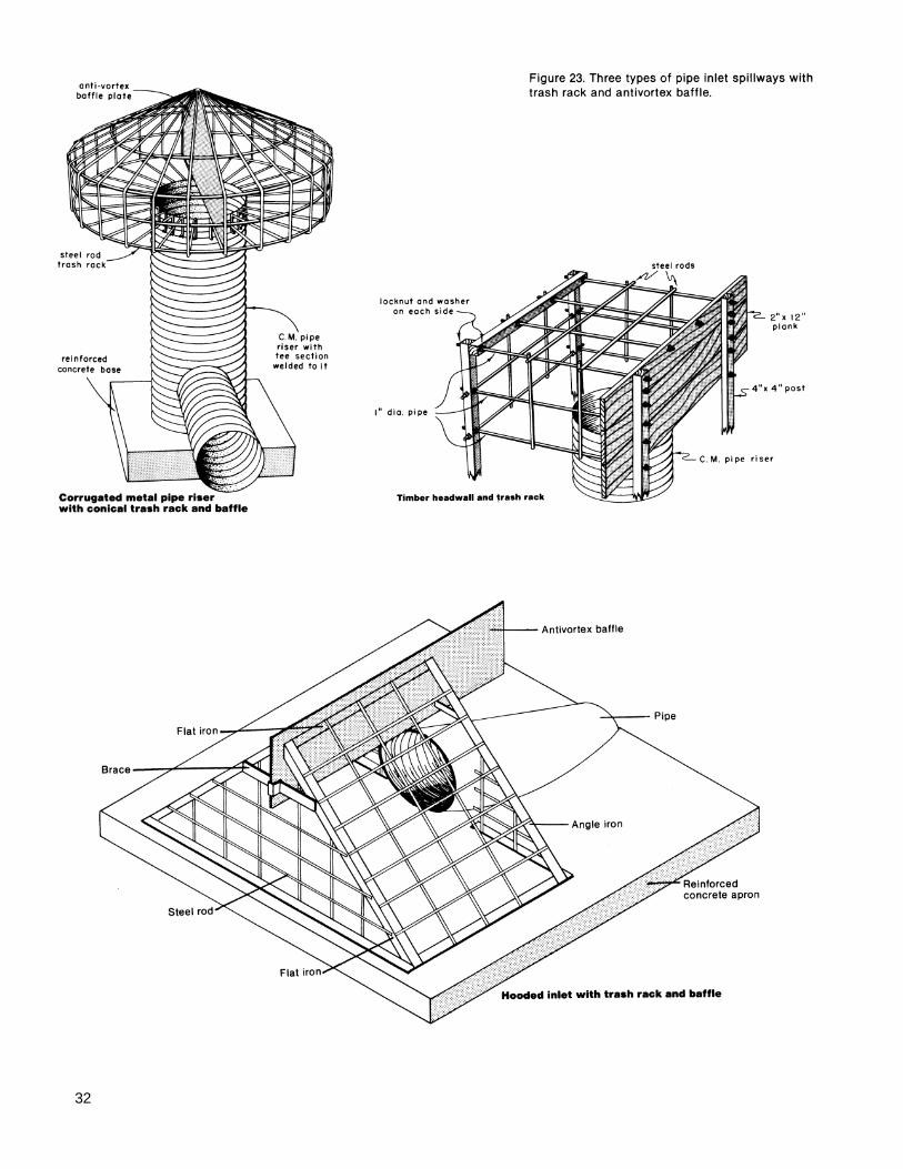
Hood-inlet trickle tubes. A hood-inlet trickle tubeconsists of a pipe laid in the earthfill (fig. 22 p. 31). Theinlet end of the pipe is cut at an angle to
Figure 20..A drop-inlet trickle tube withantiseep collar.
1Length of pipe barrel used in calculations is based on a dam with a 12-foot top width and 2.5:1 side slopes. Dischargevalues are based on a minimum head on the riser crest of 12 inches. Pipe flow based on Manning's n = 0.012.
28

Figure 21. A drop-inlet pipe spillway with drainpipe.
foundation and good alignment of the conduit. Sealthe joints of concrete pipe with an approved type ofrubber gasket to give them the desired amount offlexibility. For all trickle tubes use new pipe or pipe soslightly used that it may be considered equivalent tonew pipe.
To retard seepage through the embankment alongthe outside surface of the pipe, compact the fill aroundthe pipe. Increase the line of seepage by usingantiseep collars. Reinforced concrete collars, 6 inchesor more thick, are used with concrete,asbestos-cement, and cast-iron pipe. Either concreteor steel collars are suitable for smooth steel pipe.Special metal diaphragms are available for corrugatedmetal pipe. Plastic diaphragms can be used for plasticpipe.
Antiseep collars should extend into the fill aminimum of 24 inches perpendicular to the pipe. If thedam is less than 15 feet high, one antiseep collar atthe centerline of the fill is enough. For higher dams,use two or more collars equally spaced be-
form a hood. An antivortex device, usually metal, isattached to the entrance of the pipe to increase thehydraulic efficiency of the tube. Typical installationsof hood inlets and details of the antivortex device areshown in figure 23 (p. 32). Often a hoodinlet tubecan be built at less cost than a drop-inlet tubebecause no riser is needed. This kind of trickle tubehas one major disadvantage-it cannot be used as adrain.
The required diameter for a hood-inlet trickletube can be selected from table 11 or table 12 (p. 30)after estimating the discharge capacity, Q, anddetermining the total head,. H. The tables also showthe minimum head, h, required above the invert orcrest elevation of the tube entrance. Unless you pro-vide this minimum head, the tube will not flow full.
Pipe made of cast iron, asbestos cement,smooth steel, concrete, plastic, or corrugated metalis suitable for either kind of trickle tube. All jointsmust be watertight. A concrete cradle or bedding isneeded for concrete and asbetos-cement pipe toensure a firm
Table 10.-Discharge values for trickle tubes of corrugated metal pipe 1
Ratio of barrel diameter to riser diameter in inches
1Length of pipe barrel used in calculations is based on a dam with a 12-foot top width and 2.5:1 side slopes. Dischargevalues are based on a minimum head on the riser crest of 12 inches. Pipe flow based on Manning's n = 0.025.
29
Total head(feet) 6:8 8:10 10:12 12:15 15:21 18:25
ft3/s ft3/s ft3/s ft3/s ft3/s ft3/s6 0.85 1.73 3.1 5.1 8.8 14.18 .90 1.85 3.3 5.4 9.4 15.0
10 .94 1.96 3.5 5.7 9.9 15.912 .98 2.07 3.7 6.0 10.4 16.714 1.02 2.15 3.8 6.2 10.8 17.516 1.05 2.21 3.9 6.4 11.1 18.118 1.07 2.26 4.0 6.6 11.4 18.620 1.09 2.3 4.1 6.7 11.7 18.922 1.11 2.34 4.2 6.8 11.9 19.324 1.12 2.37 4.2 6.8 12.1 19.626 1.13 2.4 4.3 7.0 12.3 19.9

Table 11.-Minimurn head, h, required above the invert of hood inlets to provide full flow, Q,for various sizes of smooth pipe and values of total head, H 1
Total head H Diameter of pipe in inches(feet) 6 8 10 12 15 18
6 .................. h = 0.63 h = 0.85 h = 1.04 h = 1.23 h =1.54 h = 1.82Q = 1.63 Q = 3.0 Q = 5.3 Q = 8.5 Q =14.0 Q = 21.2
8 .................. h = .65 h = .86 h = 1.06 h = 1.27 h =1.57 h = 1.87Q = 1.78 Q = 3.5 Q = 6.0 Q = 9.3 Q =15.5 Q = 23.3
10 ................ h = .66 h = .87 h = 1.08 h = 1.30 h =1.60 h = 1.91Q = 1.93 Q = 3.8 Q = 6.6 Q = 10.2 0 =17.0 Q = 25.4
12 ................ h = .67 h = .88 h = 1.09 h = 1.32 h =1.63 h = 1.94Q = 2.06 Q = 4.1 Q = 7.1 Q = 10.9 Q =18.3 Q = 27.5
14 ................ h = .67 h = .89 h = 1.11 h = 1.33 h =1.65 h = 1.96Q = 2.18 Q = 4.3 Q = 7.5 Q = 11.6 Q =19.5 Q = 29.4
16 ................ h = .68 h = .90 h = 1.13 h = 1.35 h =1.67 h = 1.98Q = 2.28 Q = 4.5 0 = 7.8 Q = 12.2 Q =20.5 Q = 31.0
18 ................ h = .69 h = .91 h = 1.14 h = 1.36 h =1.69 h = 2.00Q = 2.36 Q = 4.7 Q = 8.1 Q = 12.7 Q =21.4 Q = 32.5
20 ................ h = .69 h = .92 h = 1.15 h = 1.37 h =1.70 h = 2.02Q = 2.43 Q = 4.9 Q = 8.4 Q = 13.2 Q =22.2 Q = 33.9
22 ................ h = .70 h = .93 h = 1.16 h = 1.38 h =1.71 h = 2.04Q = 2.50 Q = 5.0 Q = 8.7 Q = 13.6 Q =23.0 Q = 35.1
24 ................ h = .70 h = .93 h = 1.16 h = 1.39 h =1.72 h = 2.05Q = 2.56 Q = 5.1 Q = 9.0 Q = 14.0 Q =23.7 Q = 36.3
26 ................ h = .71 h = .94 h = 1.17 h = 1.40 h =1.73 h = 2.07Q = 2.60 Q = 5.2 Q = 9.3 Q = 14.4 Q =24.4 Q = 37.5
1Length of pipe used in calculations is based on a dam with a 12 -foot top width and 2.5:1 side slopes. Pipe flow based onManning's n = 0.012.
Table 12.-Minimum head, h, required above the invert of hood inlets to provide full flow, Q,for various sizes of corrugated metal pipe and values of total head, H 1
Total head H Diameter of pipe in inches(feet) 6 8 10 12 15 18
6 ................... h = 0.59 h = 0.78 h = 0.97 h = 1.17 h = 1.46 h = 1.75Q = .92 Q = 1.9 Q = 3.3 Q = 5.3 Q = 9.1 Q = 14.5
8 ................... h = .59 h = .79 h = .98 h = 1.18 h = 1.48 h = 1.77Q = 1.00 Q = 2.1 Q = 3.6 Q = 5.8 Q = 10.0 Q = 16.0
10 .................. h = .60 h = .79 h = .99 h = 1.19 h = 1.49 h = 1.79Q = 1.06 Q = 2.2 Q = 3.9 Q = 6.3 Q = 10.9 Q = 17.3
12 .................. h = .60 h = .80 h = 1.00 h = 1.20 h = 1.50 h = 1.80Q = 1.12 Q = 2.3 Q = 4.2 Q = 6.7 Q = 11.6 Q = 18.5
14 .................. h = .61 h = .81 h = 1.01 h = 1.21 h = 1.51 h = 1.82Q = 1.18 Q = 2.4 Q = 4.4 Q = 7.1 Q = 12.2 Q = 19.6
16 .................. h = .61 h = .81 h = 1.01 h = 1.21 h = 1.52 h = 1.82Q = 1.22 Q = 2.5 Q = 4.6 Q = 7.4 Q = 12.7 Q = 20.5
18 .................. h = .61 h = .81 h = 1.02 h = 1.22 h = 1.53 h = 1.83Q = 1.26 Q = 2.6 Q = 4.8 Q = 7.6 Q = 13.2 Q = 21.3
20 .................. h = .62 h = .82 h = 1.03 h = 1.23 h = 1.54 h = 1.85Q = 1.30 Q = 2.7 Q = 4.9 Q = 7.8 Q = 13.7 Q = 21.9
22 .................. h = .62 h = .83 h = 1.03 h = 1.24 h = 1.55 h = 1.86Q = 1.33 Q = 2.8 Q = 5.0 Q = 8.0 Q = 14.1 Q = 22.5
24 .................. h = .63 h = .83 h = 1.04 h = 1.25 h = 1.56 h = 1.88Q = 1.35 Q = 2.8 Q = 5.1 Q = 8.2 Q = 14.5 Q = 23.0
26 .................. h = .63 h = .84 h = 1.05 h = 1.26 h = 1.58 h = 1.89Q = 1.37 Q = 2.9 Q = 5.2 Q = 8.3 Q = 14.7 Q = 23.4
1Length of pipe used in calculations is based on a dam with a 12 -foot top width and 2.5:1 side slo pes. Pipe flow based onManning's n = 0.025.
30

tween the fill centerline and the upstream end ofthe conduit.
Use trash racks to keep trickle tubes fromclogging with trash and debris. Of the many kinds ofracks that have been used, three have proved verysuccessful (fig. 23 p. 32).
Extend the pipe 8 to 10 feet beyond the down-stream toe of the dam to prevent damage by theflow of water from the pipe. For larger pipes, supportthe extension with a timber brace.
Drainpipes. Some state regulatory agenciesrequire that provision be made for draining pondscompletely or for fluctuating the water level to eliminatebreeding places for mosquitoes. Whether compulsoryor not, provision for draining a pond is desirable andrecommended. It permits good pond management forfish production and allows maintenance and repairwithout cutting the fill or using siphons, pumps, or otherdevices to remove the water. Install a suitable gate orother control device and extend the drainpipe to theupstream toe of the dam to drain the pond.
Water-Supply Pipes. If water is to be used atsome point below the dam for supplying a stockwatertrough, for irrigation, or for filling an orchard spray tank,provide a water-supply pipe that runs through the dam(fig. 24 p. 33). This pipe is in addition to the trickle tube.A water-supply pipe should be rigid and havewatertight joints, a strainer at its upper end, and a valveat its outlet end. For a small rate of flow, such as thatneeded to fill stockwater
troughs, use 1-1/2-inch-diameter steel or plastic pipe.For a larger rate of flow, such as that needed forirrigation, use steel, plastic, or asbestos-cement pipeof larger diameter. Water-supply pipes also shouldhave watertight joints and antiseep collars.
Planning an Earthfill Dam
Foundations. You can build a safe earthfill damon almost any foundation if you thoroughly investigatethe foundation and adapt the design and constructionto the conditions. Some foundation conditions requireexpensive construction measures that cannot bejustified for small ponds.
The most satisfactory foundation consists of or isunderlain at a shallow depth by a thick layer ofrelatively impervious consolidated clay or sandy clay. Ifa suitable layer is at or near the surface, no specialmeasures are needed except removing the topsoil andscarifying or disking to provide a bond with the materialin the dam.
If the foundation is sand or a sand-gravel mixtureand there is no impervious clay layer at a depth thatcan be reached economically with availableexcavating equipment, an engineer should design thedam. Although such foundations may be stable,corrective measures are needed to prevent excessiveseepage and possible failure. A foundation consistingof or underlain by a highly plastic clay orunconsolidated material requires careful investigationand design to obtain stability. If the foundationconsists of such materials, consult an engineer.
31
32

Water impounded on bedrock foundations seldomgives cause for concern unless the rock containsseams, fissures, or crevices through which water mayescape at an excessive rate. Where rock is found inthe foundation, investigate the nature of the rock verycarefully.
Cutoffs. If the dam's foundation is overlain byalluvial deposits of pervious sands and gravels at ornear the surface and rock or clay at a greater depth,seepage in the pervious stratum must be reduced toprevent possible failure of the dam by piping. Toprevent excessive seepage you need a cutoff to jointhe impervious stratum in the foundation
Figure 25. Cutting a core trench on thecenterline of a dam.
Figure 24. Water is piped through the dam's drainpipe to astockwater trough.
with the base of the dam. The most common kind ofcutoff is made of compacted clayey material. A trenchis cut along the centerline of the dam deep enough toextend well into the impervious layer (fig. 25). Thistrench extends into and up the abutments of the damas far as there is any pervious material that mightallow seepage. The bottom of the trench should be noless than 8 feet wide and the sides no steeper than1:1. Fill the trench with successive thin layers of clayor sandy clay material. Compact each layerthoroughly at near-optimum moisture conditionsbefore placing the next layer.
Top Width and Alignment. For dams less than 10feet high, a conservative minimum top width is 6 feet.As the height of the dam increases, increase the topwidth. The recommended minimum top width for earthembankments of various heights is:
Height of dam
(feet)
Under 10 ................................ 611 to 14.................................. 815 to 19.................................. 1020 to 24.................................. 1225 to 34.................................. 14
Minimum topwidth(feet)
If the top of the embankment is to be used for aroadway, provide for a shoulder on each side of theroadway to prevent raveling. The top width should beat least 16 feet. In some situations a curved damalignment is more desirable than a straight alignment.Curvature can be used to retain existing landscapeelements, reduce the apparent size of the dam, blendthe dam into surrounding natural landforms, andprovide a natural-appearing shoreline.
33

Side Slopes. The side slopes of a dam dependprimarily on the stability of the fill and on the strengthand stability of the foundation material. The morestable the fill, the steeper the side slopes. Unstablematerials require flatter side slopes. Recommendedslopes for the upstream and downstream faces ofdams built of various materials are shown in table 13.
For stability, the slopes should not be steeperthan those shown in table 13 but they can be flatter aslong as they provide surface drainage. The side slopesneed not be uniform but can be shaped to blend withthe surrounding landforms (fig. 26).
Finish-grading techniques used to achieve asmooth landform transition include slope rounding atthe top and bottom of cuts or fills and on side slopeintersections, and slope warping to create variety inthe horizontal and vertical pitch of finished slopes(fig. 27). Additional fill can be placed on thebackslope and abutments of the dam, if needed, toachieve this landform transition.
Freeboard. Freeboard is the additional height ofthe dam provided as a safety factor to preventovertopping by wave action or other causes. It is thevertical distance between the elevation of the watersurface in the pond when the spillway is discharging atdesigned depth and the elevation of the top of the damafter all settlement. If your pond is less than 660 feetlong, provide a freeboard of no less than 1 foot. Forponds between 660 and 1,320 feet long, the minimumfreeboard is 1.5 feet. For ponds up to one-half milelong, the minimum freeboard is 2 feet; for longerponds an engineer should determine the freeboard.
Settlement Allowance. Settlement or consolida-tion depends on the character of the materials in
both the dam and the foundation and on the con-struction method. To allow for settlement, build earthdams somewhat higher than the design dimensions. Ifyour dam is adequately rolled in thin layers under goodmoisture conditions, there is no reason to expect anyappreciable settlement in the dam itself but thefoundation may settle. For a rolled-fill dam onunyielding foundation, settlement is negligible.
Most foundations are yielding, and settlementmay range from 1 to 6 percent of the height of thedam, mainly during construction.
The settlement allowance for a rolled-fill damshould be about 5 percent of the designed damheight. In other words, the dam is built 5 percenthigher than the designed height. After settlement,the height of the dam will be adequate.
Most pond dams less than 20 feet high, however,are not rolled fill. For these dams the total settlementallowance should be about 10 percent.
Estimating the Volume of the Earthfill. Afterplanning is completed, estimate the number of cubicyards of earth excavation required to build the dam.This helps estimate the cost of the dam and serves asa basis for inviting bids and for awarding a contract.
Table 13.-Recommended side slopes for earthdams
Fill materialSlope
Upstream DownstreamClayey sand, clayey gravel, sandyclay, silty sand, silty gravel ..... .......... 3:1 2:1
Silty clay, clayey silt .......................... 3:1 3:1
34
Figure 26. Dam sideslopes are curvedand shaped to blendwith surroundingtopography.

The estimate of the volume of excavation shouldinclude the volume in the dam itself including theallowance for settlement, the volume required tobackfill the cutoff trench, the volume required tobackfill stream channels or holes in the foundationarea, and any other volume of earth the contractor isrequired to remove.
Volume estimates for dams are usually made ofthe required number of cubic yards of earthfill in place.Probably the most efficient method of estimating thevolume of earthfill is the sum-of-end-area method. Theground surface elevations at all points along thecenterline of the dam where the slope changessignificantly are established by the centerline profile.With the settled top elevation of the dam established,you can obtain the settle fill height at each of thesepoints by subtracting the ground surface elevation fromthe settle top elevation. With the fill heights, sideslopes, and top width established, find the end areas ateach of these points along the centerline in table 14(pp. 36 and 37).
For example, assume that a dam has slopes of 3:1on both upstream and downstream sides and a topwidth of 12 feet. For a point along the centerline wherethe fill is 15 feet high, the table shows that the end areaat that point is 675 plus 180, or 855 square feet. Thenumber of cubic yards of fill between two points on thecenterline of the dam is equal to the sum of the endareas at those two points multiplied by the distancebetween these points and divided by 54. The totalvolume of earthfill in the dam is the sum of all suchsegments. A sample volume estimate illustrating theuse of the sum-of-end-areas method is shown in table15 (p. 38).
The sample volume estimate of 7,732 cubic yardsincludes only the volume of earth required to completethe dam itself. Estimate the volume of earth required tobackfill the core trench, old stream channels, and otherrequired excavation and
Figure 27. Finish-grading techniques.
add it to the estimate for the dam. Also include anestimate of additional fill to be placed on the backslope and abutments. For example, assume that, inaddition to the volume shown in table 15, there is acutoff trench to be backfilled. The dimensions of thetrench are:
Average depth = 4.0 ft
Bottom width = 8.0 ft
Side slopes = 1:1
Length = 177 ft
Compute the volume of backfill as follows:
End area = (8 x 4) + (4 X 4) = 48 ft2
Add this to the volume required for the dam andthe total volume is 7,732 plus 315 or 8,047 cubicyards.
Plans and Specifications. Record all planninginformation on an engineering plan. This plan shouldshow all elevations and dimensions of the dam, thedimensions and extent of the cutoff trench and otherareas requiring backfill, the location and dimensions ofthe trickle tube and other planned appurtenances, andany other pertinent information. The plan should alsoinclude a list of the quantity and kind of buildingmaterials required. Unless you have all the necessaryequipment, you will need to employ a contractor tobuild the pond. You may wish to receive bids fromseveral
35

Side slopes Top width (feet)
2.5:1 2.5:1 3:1 3.5:1 4:1Fill height 2.5:1 3:1 3:1 3.5:1 4:1 8 10 12 14 16(feet) 2:1 2:1 2.5:1 3:1 3:1
3:1 3.5:1 3.5:1 4:1 5:1
1.0 3 3 3 4 4 8 10 12 14 161.2 4 4 4 5 6 10 12 14 17 191.4 5 5 6 7 8 11 14 17 20 221.6 6 7 8 9 10 13 16 19 22 261.8 8 9 10 11 13 14 18 22 25 292.0 10 11 12 14 16 16 20 24 28 322.2 12 13 15 17 19 18 22 27 31 352.4 14 16 17 20 23 19 24 29 34 392.6 17 19 20 24 27 21 26 31 36 422.8 20 22 23 27 31 22 28 34 39 453.0 22 25 27 32 36 24 30 36 42 483.2 26 28 31 36 41 26 32 38 45 513.4 29 32 35 40 46 27 34 41 47 553.6 32 36 39 45 52 29 36 43 50 583.8 36 40 43 50 58 30 38 46 53 614.0 40 44 48 56 64 32 40 48 56 644.2 44 49 53 62 71 34 42 50 59 674.4 48 53 58 68 77 35 44 53 61 714.6 53 58 63 74 85 37 46 55 64 744.8 57 63 69 81 92 38 48 57 67 775.0 62 69 75 87 100 40 50 60 70 805.2 67 74 81 94 108 42 52 62 73 835.4 73 80 87 102 117 43 54 65 75 875.6 78 86 94 110 125 45 56 67 78 905.8 84 93 101 118 135 46 58 69 81 936.0 90 99 108 126 144 48 60 72 84 966.2 96 106 115 135 154 50 62 74 87 996.4 102 113 123 143 164 51 64 77 89 1036.6 109 120 131 152 174 53 66 79 92 1066.8 116 128 139 162 185 54 68 81 95 1097.0 123 135 147 172 196 56 70 84 98 1127.2 130 143 156 182 207 58 72 86 101 1157.4 138 152 165 193 219 59 74 89 103 1197.6 145 159 174 203 231 61 76 91 106 1227.8 153 168 183 214 243 62 78 93 109 1258.0 160 176 192 224 256 64 80 96 112 1288.2 169 185 202 235 269 66 82 98 115 1318.4 177 194 212 247 282 67 84 101 117 1358.6 186 204 222 259 296 69 86 103 120 1388.8 194 213 232 271 310 70 88 105 123 1419.0 203 223 243 283 324 72 90 108 126 1449.2 212 233 254 296 339 74 92 110 129 1479.4 222 244 266 310 353 75 94 113 131 1519.6 231 254 277 323 369 77 96 115 134 1549.8 241 265 289 337 384 78 98 117 137 15710.0 250 275 300 350 400 80 100 120 140 16010.2 260 286 313 364 416 102 122 143 16310.4 271 298 325 379 433 104 125 145 16710.6 281 309 338 394 449 106 127 148 17010.8 292 321 350 409 467 108 129 151 17311.0 302 333 363 424 484 110 132 154 17611.2 313 344 376 440 502 112 134 157 17911.4 325 357 390 456 520 114 137 159 18311.6 336 370 404 472 538 116 139 162 18611.8 348 383 418 488 557 118 141 165 18912.0 360 396 432 504 576 120 144 168 192
See footnote at end of table.
Table 14.-End areas in square feet of embankment sections for different side slopes and top widths 1
36