Polymers & Lasers - vestamid.com · Polymer Materials Solution Provider The Laser Application...
48
Polymers & Lasers Laser Application Center
Transcript of Polymers & Lasers - vestamid.com · Polymer Materials Solution Provider The Laser Application...

Polymers & LasersLaser Application Center

Performance Polymers Laser Application Center

Contents
Introduction ……………………………………………………………….
High Performance Polymers from Evonik ……………………………
Laser Application Center ………………………………………………
Laser Technolgy …………………………………………………………
What is laser radiation? ……………………………………………………
Types of Laser ……………………………………………………………
Solid-State Lasers …………………………………………………………
Semiconductor Lasers ……………………………………………………
Gaslaser ……………………………………………………………………
Other Types of Laser ………………………………………………………
Polymers and Lasers ……………………………………………………
Requirements ………………………………………………………………
Factors Influencing Laser-Welding of Plastics ……………………………
Optical Properties of Plastics ………………………………………………
Transmission Spectra ………………………………………………………
Laser-Marking ……………………………………………………………
Factors Impacting Laser-Marking …………………………………………
Laser-Marking Non-Transparent Plastics .……………………………
Marking Lasers ……………………………………………………………
Lettering and Contrast on Non-Transparent Plastics ………………
Laser-Marking of Transparent Plastics ………………………………
Laser-Marking by NIR Absorbers …………………………………………
2D Laser-Marking of Transparent Plastics …………………………
3D Sub-Surface Laser-Engraving of Transparent Plastics …………
Basics of 3D Sub-Surface Laser-Engraving …………………………
6
7
8
9
9
11
12
13
13
13
14
14
15
16
17
18
18
19
19
20
21
21
23
24
25

3D Sub-Surface Laser-Engraving of Transparent Plastics …………
3D Laser for Sub-Surface Engraving ……………………………………
Advantages of Laser-Sensitive, Transparent,
Colorless Plastics .…………………………………………………………
Advantages of Laser-Marking .…………………………………………
Laser-Welding of Plastics .………………………………………………
Degrees of Difficulty in Laser-Welding .………………………………….
The Laser-Welding Process .……………………………………………
Weld Seam Quality .………………………………………………………
Factors affecting weld seam quality in thermoplastics .………………….
Laser-Welding Processes .……………………………………………….
Contour Welding .…………………………………………………………..
Simultaneous Welding .…………………………………………………….
Quasi Simultaneous Welding .……………………………………………..
Mask Welding .……………………………………………………………...
Application Areas …..………………………………………………………
Advantages .…………………………………………………………………
Laser-Structuring .………………………………………………………..
Laser-Sintering .…………………………………………………………...
Requirements on Laser-Processable Molding Compounds .………
Application Profiles Laser-Marking .……………………………………...
Application Profiles Laser-Welding .………………………………………
Requirements on Laser-Workable Molding Compounds .………………
Requirements Profile Laser-Structuring .…………………………………
26
27
27
28
29
30
31
32
32
33
33
33
34
34
35
35
36
37
38
38
38
38
38

Laser Additives .…………………………………………………………...
Additives for Non-Transparent Molding Compounds .………………….
Additives for (Highly) Transparent, Colorless Molding Compounds .…
Laser-Processable Molding Compounds .…………………………….
VESTODUR®..................................................................................
VESTORAN®..................................................................................
TROGAMID®.................................................................................
VESTAMID®...................................................................................
VESTAKEEP®.................................................................................
Laser-Processable Semifinished Products .…………………………..
EUROPLEX®...................................................................................
PLEXIGLAS®..................................................................................
Environmental Aspects .………………………………………………….
Emissions .…………………………………………………………………...
Recycling .……………………………………………………………………
Quality .……………………………………………………………………..
Future Prospects .…………………………………………………………
Classes of Lasers .…………………………………………………………
DIN EN 60825-1 Classification .…………………………………………..
Literature and Sources .…………………………………………………..
39
39
39
40
40
40
41
41
41
42
42
42
43
43
43
43
44
45
45
46
Performance Polymers
Application possibilities for laser systems used in processing plastics are virtually unlimited. Fast, flexible, and precise, laser technology is more cost efficient than conventional processes; moreover, this advanced technology brings innovative ideas to rapid implementation and adds years to the life of processed materials.
Where products are marked with bar-codes, contour sharpness is important, as is contrast. Only if the marking stands out clearly from the material surface can it be correctly read by a bar code scanner and processed further.
The miniaturization of components and their increasingly complex geometries require welds of such fineness that con-ventional welding processes can obtain them only with great difficulty, if at all. The laser-welding process, on the other hand, makes it possible to do even three-dimensional welding in a single workstep. In the manufacture of sensors for medical engineering, the laser can produce the fi-nest welds in the most confined of spaces.The conventional manufacture of three-dimensional circuit substrates depends on product-specific tools for creating the
printed circuit structure on the compo-nent, which severely limits the flexibility of the processes when designs are chan-ged. Further miniaturizing printed circuit structures on MID components requires additional time and cost. Using special molding compounds in conjunction with the appropriate laser-structuring techno-logy offers a flexible and cost-effective alternative.
In design studies, modeling, and even in very small-scale production, parts are still often produced manually because the high cost of tools rules out the fabrication of injection-molded parts. Laser-sintering offers an economical alternative here. The parts need only be developed on a CAD system and then constructed as hardware in a subsequent rapid prototyping process.
The scope of application of plastics de-pends strongly on their material proper-ties and their compatibility with the laser wavelengths used in the various systems. Not all of the currently used thermoplas-tics absorb laser beams equally well. But thanks to special additives developed and patented by Evonik’s Performance Polymers and Inorganic Materials Business
Units, our molding compounds can be ad-justed for use in an extremely wide range of applications.
The components made from these molding compounds ensure good laser weldability of two transparent materials and, for laser-marking, dark lettering of the highest quality, even for highly trans-parent and colorless plastics. Moreover, the High-Performance Polymers Business Line offers various black and dark-colored products that can be laser-marked to give light-on-dark images with good contrast.
For the selection of a suitable laser-pro-cessable material, the requirements profile for the molded part must be known. The following table of laser-processable molding compounds from our high-performance polymers product range will help you draw up a short list of suitable materials. We recommend that you consult us as your knowledgeable partner before beginning a new project. Our Laser Application Center has the skills to select the molding compounds that are optimal for you, and to identify fast and economic-al processing options when these materi-als are used.
Introduction
6

7
High Performance Polymers from Evonik

Laser Application Center
Laser Sintering Laser Printing Laser Engraving Laser Welding Laser Direct Structuring
IndustrialPartners:
Laser Technologies
Customers:Problems
Applications
High Performance Polymers:
Polymer Materials
Solution Provider
The Laser Application Center of High Performance Polymers offers support in the use of lasers with polymers, in the form of:
• comprehensive advice, • state-of-the-art technology, and • quality testing
Polymers & Lasers
The Laser Application Center supports you in choo-sing materials for all relevant laser processes.You are welcome to try out the following laser appli-cations at the Center:
• Laser-marking (2D and 3D)• Laser-welding• Laser-sintering• Laser-structuring
Quality
In our testing and analytical laboratories, we can perform a wide range of tests on lasered and un-lasered materials to check and safeguard our high quality standards. These include
• transmission measurements,• haze,• scanning electron microscopy (SEM),• transmission electron microscopy (TEM), • light microscopy, and• tensile testing
as well as many other physical and chemical tests.
8

Laser Technology
What is laser radiation?
The word laser is an acronym for Light Amplification by Stimulated Emission of Radiation, and describes a physical process leading to the production of laser radiation.
In the first step, atoms1) of a laser medium (the active medium) are excited by supplying them with energy, a process known as “pumping” (see diagram). The active medium may be a liquid, solid, or gas.
end mirror front mirror(totally reflecting) (partly transparent)
optical resonator
Fig. 1: Structure of a laser
• coherence: the waves possess a constant phase difference; they are temporally and spatially coherent;• monochromatic light: laser radiation has exactly one wavelength;• low divergence: lasers emit bundled, almost parallel radiation.
1) These may be atoms, molecules, or ions; for the sake of brevity they will be referred to in the following as atoms
laser pumping energy
Depending on the active medium, the energy can be supplied by electrical gas discharges, flash lamps, an applied voltage, or another laser. The excited atoms emit photons (light particles), thereby returning to the non-excited state. If these light particles collide with other atoms in the excited state, the latter also emit light particles of the same wavelength, phase, and direction as the incident light particles. This pro-cess, known as “stimulated emission,” is what occurs in an optical resonator.
The resonator may be, for example, a (gas-filled) tube or a solid (such as ruby, or a semiconductor), at both ends of which a mirror reflects the radiation. This therefore traverses the active medium many times, stimulating further atoms to give up their light par-ticles on each pass. One of the two mirrors is partly
transparent, so that part of the radiation can emerge from the tube.Laser radiation differs essentially from radiation emitted by conventional radiation sources, such as incandescent lamps, in the following ways:
9

• monochromatic (a single color)• luminous power of the order of mW to MW• spatially and temporally coherent• directional “laser beam” radiation• good bundling (focusing) of the beam
• “white” light, emitting a broad spectrum• luminous power of the order of mW to W• not coherent• omnidirectional radiation
IR
Fig. 2: Normal light Fig. 3: Laser light
light source prism spectrum UV
In practice, this means that laser beams can be strongly bundled and easily focused on the smallest spaces. This property is exploited in every CD player, for example, to read out the microscopically small structures on the CD. On the other hand, laser beams also allow enormous energies to be bundled at a single point, for example, for very precise cutting, marking, or welding of materials.
Because lasers are used for a wide range of different purposes, they differ also in their structure. The wavelengths range from the far infrared (IR) region through visible light to the ultraviolet (UV) region (see Fig. 4).
Fig. 4: The electromagnetic spectrum
10

Types of Laser
Lasers are categorized and named according to the type of the optically active material used; they may be gas, solid, or liquid (or dye) lasers (Fig. 5).
Fig.5: Typical lasers and their wavelengths
Lasers can also be classified according to whether they radiate continuously (cw (continuous wave) lasers, Fig. 6) or operate in a pulsed mode. Lasers radiating for a period exceeding 0.25 s are known as continuous wave lasers. Pulsed lasers emit radiation pulses at regular intervals; the duration of these pulses may range from a few femtoseconds to 0.25 seconds (Fig. 7).
Fig. 6: Continuous wave (cw) laser Fig. 7: Pulsed laser
Time(t) Time (t)
Pow
er (P
)
Pow
er (P
)
PL
T
tP
PS
Pm
PL = laser power (W) PS = peak power (W) Pm = mean power (W) T = pulse period tp = pulse duration
11

Solid-State Lasers
The first working laser was a ruby laser, made from ruby (chromium-doped corundum), developed by Maiman in the year1960.Solid-state laser materials are commonly made by doping a crystalline solid host with ions provide the required energy states. Embedded in the host mate-rial, these ions form the actual active medium. Their orbitals do not participate in chemical bonding. The carrier material (host crystal or glass) therefore has only a small influence on the properties of the ions. Solid-state lasers are distinguished according to the type and form of the host material and the doped elements.
Examples of host or carrier materials
Glass (in the form of rods or fiber lasers)• • Advantage: simple to produce, even in large dimensions • Disadvantages: low thermal conductivity, low strength
Al• 2O3 (corundum, sapphire; e.g., ruby laser (chromium doped), titanium:sapphire laser)
• Advantages: high thermal conductivity, high strength • Disadvantages: relatively high absorption; expensive
YAG (yttrium aluminum garnet laser: see • Nd:YAG laser), doped with Nd, Er, Yb
• Advantages: high thermal conductivity, high strength, low absorption • Disadvantage: expensive
Yttrium vanadate (YVO• 4), doped with Nd
Examples of Doping Materials
The doping material in the first ever laser, the • ruby laser (694.3 nm, red), was chromium. Be-cause of its low efficiency it is now rarely used.Neodymium, is used in the most important com-• mercial solid-state lasers, Nd:YAG at 1064 nm (infrared) and double frequency at 532 (green). Nd:glass and Nd:YLF are also possible.Ytterbium, allows high efficiency (>50%) in la-• ser operation, but needs narrow-band pumping with laser diodes (940 nm). The most important material with this dopant is the Yb:YAG laser, for example, highly doped as a thin disk laser with a wavelength of 1030 nm.Titanium; an important mode-coupled solid-sta-• te laser is the titanium:sapphire laser, 670-1100 nm (red-infrared), which due to broadband amplification is suitable for pulses in the fs range.Erbium, 3 μm, pumping with diode laser at 980 • nm; known as the eye-safe laser, this is used for laser range finders and in medicine.
Types of Active Media
Rod lasers• Microcrystal lasers• Slab lasers• Fiber lasers• Thin disk lasers•
12

Semiconductor Lasers
In semiconductor lasers, the active medium is the dif-fusion zone of the charge carriers in a p-n transition1) of a semiconductor crystal. The optical resonator can be formed here by the end faces of the semiconduc-tor crystal, because the high refractive index of the crystal results in high reflectivity.Laser diodes are directly electrically pumped lasers. The power of laser diodes lies between < 1W and 10W. The beam quality declines with increasing power.A number of individual diodes can be assembled side by side on a single narrow chip (approx. 0.1 x 1 x 10 mm). These “bars”, as they are known, can supply more than 50 watts if mounted on a heat sink, with the individual diodes electrically connected in paral-lel. The mounted bar is also known as a “submount.” By coupling a number of bars or submounts in a stack, outputs in the kW range can be achieved, with corres-pondingly poor beam quality. By the use of different (normally up to 3) wavelengths and polarization directions, up to 6 stacks can be optically added with low losses and without deterioration of beam quality. For optical pumping of solid-state lasers by laser dio-des, the pump wavelength must be matched exactly and wavelength coupling is therefore not possible. However, the diode lasers need not be combined here into beams with high power density.
Diode lasers with wavelengths in the range of approx. 800 nm to 1000 nm are now, in addition to Nd:YAG lasers (1064 nm), the most important industrial lasers for processing of plastics.
Other semiconductor lasers include:
optically pumped semiconductor lasers, inclu-• ding semiconductor thin disk lasers,quantum cascade lasers,• surface-emitting lasers (VCSEL) (optically as • well as electrically pumped), andtunable lasers (tunable laser source, TLS) with • adjustable wavelength.
Gas Lasers
In gas lasers the active medium is gaseous. Gas lasers are usually electrically pumped by a gas discharge in the active medium itself.The most important gas lasers used in the processing of polymers are:
the carbon dioxide (CO• 2) laser, with wavelength approx. 10.6 μm (mid-infrared), an important industrial laser for cutting and marking, andthe excimer laser, for example, KrF (248 nm), • XeF (351-353 nm), ArF (193 nm), XeCl (308 nm), and F2 (157 nm), for marking and fine drilling; all these are ultraviolet.
Other Types of Laser
Other types of lasers include, for example, dye lasers, color center lasers, and free-electron lasers (FEL).
1) p-n (positive-negative) transition is the boundary layer between a p-conducting and an n-conducting region in a semiconductor. The strong concentration gra-dient of the carriers at the boundary layer causes some holes to diffuse from the p- to the n-conducting layer, and some electrons in the reverse direction, where they then recombine with the respective carriers.
13

Polymers and Lasers
If plastics are used for laser-welding, the material-specific properties of the various types of plastics must be taken into particular consideration.
Thermoplastics, whether amorphous or semicrystalline, are easily fusible and have a fusion temperature range above which they decompose (Fig. 9).
In addition to morphology, fillers, such as glass fibers, also affect welding properties.
Additives
Ultra violet Infrared
Electronic excitation
400 nm 700 nm
Vibronic excitation
Nd:YAG1064 nm
Nd:YAG/SHG532 nm
Visible region
CO210.6 µm
Diode laser808, 940, 980 nm
AbsorptionPolymer
Additives
Ultra violet Infrared
Electronic excitation
400 nm 700 nm
Vibronic excitation
Nd:YAG1064 nm
Nd:YAG/SHG532 nm
Visible region
CO210.6 µm
Diode laser808, 940, 980 nm
AbsorptionAdditivesAdditives
Ultra violet Infrared
Electronic excitation
400 nm 700 nm
Vibronic excitation
Nd:YAG1064 nm
Nd:YAG/SHG532 nm
Visible region
CO210.6 µm
Diode laser808, 940, 980 nm
AbsorptionPolymer
Fig. 8: Light absorption of polymers and laser wavelengths
Requirements
Virtually any plastic can be laser processed, but material- and process-specific restrictions must be taken into account.
Plastics do not absorb laser radiation in the region extending from the near ultraviolet to the near infrared. Conversion of laser ener-gy into heat (of fusion) is therefore possible only if the polymer has been appropriately “laser sensitized” by addition of an additive.
In the absence of laser additives, therefore, polymers can be processed only in far ultraviolet light, for example, with excimer lasers, and in far infrared light, for example, with CO2 lasers (Fig. 8).
CO2
10.6 μm
14
Electron excitation Molecular excitation
Polymers
visible region

Factors Influencing Laser-Welding of Plastics
Crosslinked plastics of the thermoset and elastomer class (except for thermoplastic elastomers, TPE/TPU) are not fusible. They are therefore not suitable for laser-welding. They can, however, be used for laser-marking.
Fig. 9: Fusion and softening ranges of plastics
Fusion/softening ranges Decomposition temperature
15
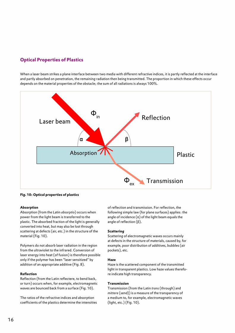
Optical Properties of Plastics
When a laser beam strikes a plane interface between two media with different refractive indices, it is partly reflected at the interface and partly absorbed on penetration, the remaining radiation then being transmitted. The proportion in which these effects occur depends on the material properties of the obstacle; the sum of all radiations is always 100%.
Reflektion
Transmission
Kunststoff
Laserstrahl
Absorbtion
α β
Reflektion
Transmission
Kunststoff
Laserstrahl
Absorbtion
α β
Reflektion
Transmission
Kunststoff
Laserstrahl
Absorbtion
Reflektion
Transmission
Kunststoff
Laserstrahl
Absorbtion
Reflektion
Transmission
Kunststoff
Laserstrahl
Absorbtion
α β
Laser beam Reflection
Plastic
Transmission
Fig. 10: Optical properties of plastics
AbsorptionAbsorption (from the Latin absorptio) occurs when power from the light beam is transferred to the plastic. The absorbed fraction of the light is generally converted into heat, but may also be lost through scattering at defects (air, etc.) in the structure of the material (Fig. 10).
Polymers do not absorb laser radiation in the region from the ultraviolet to the infrared. Conversion of laser energy into heat (of fusion) is therefore possible only if the polymer has been “laser sensitized” by addition of an appropriate additive (Fig. 8).
ReflectionReflection (from the Latin reflectere, to bend back, or turn) occurs when, for example, electromagnetic waves are bounced back from a surface (Fig. 10).
The ratios of the refractive indices and absorption coefficients of the plastics determine the intensities
of reflection and transmission. For reflection, the following simple law (for plane surfaces) applies: the angle of incidence (α) of the light beam equals the angle of reflection (β).
ScatteringScattering of electromagnetic waves occurs mainly at defects in the structure of materials, caused by, for example, poor distribution of additives, bubbles (air pockets), etc.
HazeHaze is the scattered component of the transmitted light in transparent plastics. Low haze values therefo-re indicate high transparency.
TransmissionTransmission (from the Latin trans (through) and mittere (send)) is a measure of the transparency of a medium to, for example, electromagnetic waves (light, etc.) (Fig. 10).
Фin
Фex
16 17
Absorption

Transmission Spectra
Fig. 12:Transmission spectrum of nanomodified TROGAMID® CX7323
Fig. 11:Transmission spectrum of nanomodified PMMA
TransmittanceIn optics, transmittance is the proportion of the incident radiation or light flux that completely penetrates a transparent component.The transmittance τ is defined as the quotient of the radiant flux of the emergent (transmitted) light beam (Фex) and that of the incident beam (Фin).
τ = Фex/Фin
The transmittance depends on, among other factors, the wavelength and therefore the frequency of the electromagnetic radiation, that is, on the color of the light, and on the angle of incidence of the wave.
16 17

Laser-Marking
The range of potential applications for laser systems in the marking of plastics is virtually unlimited. Fast, flexible, and precise, laser technology is more eco-nomical than the conventional printing and injection molding processes; moreover, this advanced techno-logy guarantees the durability and contour sharpness of the marking.For marking products with a barcode or data matrix code, contrast is important, as is contour sharpness; only when the marking stands out clearly from the material surface can it be correctly read by the bar code scanner and processed further.
The contrast and contour sharpness of laser markings depend on the material properties of the plastics used and their compatibility with the various laser systems and their wavelengths. Not all of the commonly used thermoplastics absorb laser beams equally well, and this can negatively impact the contrast or suppress it altogether.
Marking plastics in the UV, visible, and IR ranges is possible either directly or with the use of laser additives.Because the Nd:YAG laser (1064 nm, Fig. 13) is the most commonly used in practice, most molding compounds for laser-marking are now formulated for the wavelength of this laser. Exceptionally high con-trast is achieved when the materials contain special additives developed and patented by Evonik’s High Performance Polymers Business Line. Laser additives designed specially for transparent plastics have also been developed by the company’s Inorganic Materi-als Business Unit.In non-transparent plastics, these laser additives ensure dark markings of the highest quality on almost all light-colored formulations, irrespective of the pigmentation of the plastic and even for in-house
Fig. 13:Nd:YAG marking laser1064 nm (from Baasel-Lasertechnik)
coloring by customers. Additionally, the High Perfor-mance Polymers Business Line offers various dark-colored and black products that can be laser-marked in light colors with good contrast.
Highly transparent plastics from Evonik that contain laser additives are distinguished by their absolute colorlessness and very low haze. In this case also, the lettering is of the highest quality, with very good contrast.
To choose an appropriate laser-markable material, you must know the requirements profile for the part to be marked.
Factors Impacting Laser-Marking
The markability of a plastic depends only on its ma-terial properties and any laser additive used. Marking effects such as color change, foaming, and carboni-zation depend on the reciprocal effects of material properties and laser wavelength. The characteristics crucially important for high-quality marking are homogeneity of the molding compound, excellent distribution of the laser additive, and appropriate selection of laser parameters.
18 19

Writing laser
The writing laser offers flexibility. The laser beam is deflected in the x- and y-directions by two computer controlled galvanometer mirrors, and is focused with a lens on the part to be marked. An area of appro-ximately 10 x 10 cm can be marked at any required point. It is possible to provide every single part in a production line with an individual marking, such as a serial number.
Mask Laser
The mask laser is not as flexible as the writing laser, but is considerably faster. The laser beam, a few square centimeters in area, passes through a lens, imaging a mask on the part to be marked. This process allows up to 200 markings per second.
Dot-Matrix-Process
In the dot matrix process, a laser beam is “chopped” by a rotating mirror. By movement of the part to be marked, a marking consisting of a number of individual points is produced, in the same manner as on an inkjet printer. This process represents a special form of laser-marking of plastics because it can be used for only a few thermoplastics.
The Dot-Matrix-Process is suitable for batch date marking at high speed. The size of the marking is restricted, however, and marking is possible only with moved parts.
18 19
Laser-Marking Non-Transparent Plastics
Marking Lasers
Fig. 14:Writing laser
Fig.15:Mask laser
Deflection unit for the x direction
CAD-SYSTEM
Deflection mirror
Deflection unit for the y direction
Lens
Workpiece
Laser
Mask
Lens
Workpiece

Lettering and Contrast on Non-Transparent Plastics
The staining depth and foaming height can be deter-mined from light microscopic images of thin sections (Fig. 16, 17, and 18). The staining depth [a] should be at least 100 μm, and the foaming height [b] should be as low as possible. The most important parameter characterizing the marking is the legibility, which can be quantified in terms of contrast; this can be deter-mined using a luminance meter.
Fig. 16: Contrast without additive Fig. 17: Contrast with additive
Surface profile of the letter “E” with the same laser energy
Fig. 19: No additive; high
foaming height
Fig. 20: Low foaming height
achieved by use of an additive
Fig. 18: Characterization of laser-marking by evaluation of staining depth (a) and foaming height (b)
To eliminate gloss angle effects, the measurement point is illuminated by an integrating sphere with a luminosity of 200 lux. The luminances of the back-ground (BL) and characters (CL) are determined, and the contrast C is defined by the ratio BL/CL. The GS-VWSG7 test standards of the Employers’ Liability Insurance Association specify that for characters on key caps C must be > 3.
20 21

Laser-marking of transparent plastics has so far been restricted to colored thermoplastics; selective coupling in of the laser energy was not formerly possible in transparent plastics. The problem could be solved by the use of suitable additives or pigments, but at the cost of transparency and colorlessness. Evonik’s technicians have now overcome these difficulties and have succeeded in extending the process also to transparent polymers.
Laser-Marking of Transparent Plastics
A technology has been successfully developed for laser-marking transparent plastics, which are other-wise difficult or impossible to mark with lasers. This uses nanoscale metal oxides, which, on account of their small particle size, do not scatter visible light but absorb the wavelength of the laser in the near infra-red (NIR) region. Because the Nd:YAG laser (1,064 nm) is most commonly used in practice, the additives have been formulated for the wavelength of this laser. The skill in the incorporation of the metal oxides lies in controlling their tendency to agglomeration and dispersing them as homogeneously as possible in the polymer matrix. Only under these conditions can high-contrast markings with the highest resolution and contour sharpness be obtained. These infrared absorbers are dispersed in PLEXIGLAS® (polymethyl methacrylate, PMMA) and TROGAMID®, a transpa-
Laser-Marking by NIR Absorbers
Well-dispersed laser sensitive additive Aggregated laser-sensitive additive
rent polyamide, new compounding processes being used for this purpose.If a laser beam now falls on the metal oxides, they absorb the energy and heat their immediate environment, which results in foaming (by formation of gaseous degradation products in the micrometer region) or carbonization (degradation to carbon). The result is a locally confined change of refractive index, rendering the marking, such as an inscription, visible. The additives do not produce a co-lor change, but appear in a shade of gray ranging from white to black, depending on the polymer and the choice of laser parameters. In both PLEXIGLAS® and TROGAMID®, markings can be obtained with layer thicknesses of less than 100 micrometers. Multilayer designs are also possible in which the laser-sensitive layer is embedded between two transparent covering layers.
Fig: 21Dispersion of NIR absorber
20 21

Fig. 22: Mechanism of laser-marking and sub-surface engraving by NIR absorbers
Focused laser beam
Nanoscale particles absorb in the NIR
Polymer foams
Polymer carbonizes
Change of refractive index or carbonization makes the marking visible
Use of nanoscale NIR ab-sorbers
in transparent polymers such as PLEXIGLAS® (PMMA)orTROGAMID® (PA)
for laser-marking or sub-surface engraving
The possible fields of application of this new tech-nology for laser-marking (highly) transparent plastics are many and varied. Because the marking is forgery-proof and highly durable, it is suitable for, for example, identity cards, barcodes, and pharmaceuti-cal packaging. Medical technology could also benefit from this contactless process because, in contrast to other marking processes such as printing or milling, there are no impurities and no contamination with chemical compounds or abrasion particles.
Entirely different fields of application, such as perso-nalized art objects or inscriptions for office doors, are also conceivable. Evonik is now stepping up further development in cooperation with customers.
22 23
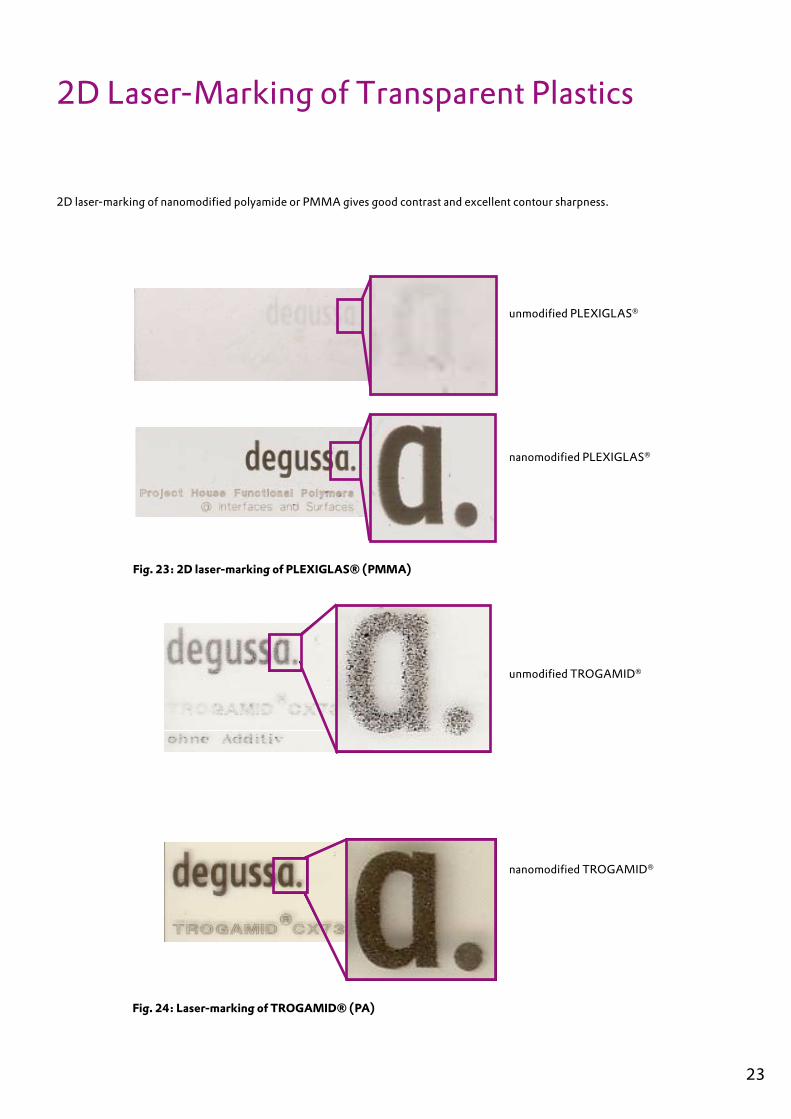
2D laser-marking of nanomodified polyamide or PMMA gives good contrast and excellent contour sharpness.
2D Laser-Marking of Transparent Plastics
unmodified TROGAMID®
nanomodified TROGAMID®
Fig. 24: Laser-marking of TROGAMID® (PA)
unmodified PLEXIGLAS®
nanomodified PLEXIGLAS®
Fig. 23: 2D laser-marking of PLEXIGLAS® (PMMA)
22 23

3D Sub-Surface Laser-Engraving of Transparent Plastics
For many years, lasers have been used for sub-surface engraving of glass to produce 2D or 3D motifs (e.g., from CAD applications), logos, patterns, and photos. The amazing possibility also exists of imaging faces with 3D face scanners to produce realistically and accurately engraved 3D motifs in glass blocks. This technology works because a 3D scanner can capture the face of a person in seconds. This “face scan” is then prepared for the laser process by special soft-ware, the photo being transformed into a dot cloud. The laser, normally a frequency-doubled Nd:YAG laser (532 nm), burns hundreds of thousands of pixels into the glass in just a few minutes, reproducing the surface and the texture of the face, hair, eyes, and other features. A high-resolution 3D representation demands optimal matching of software, laser unit (hardware), and material.
3D motifs can be laser-engraved in normal, com-mercially available acrylic glass, but resolution and brilliance are significantly poorer than in silicate glass. The poor quality of sub-surface laser engraving has so far prevented the use of acrylic glass for this purpose. Evonik has now succeeded in developing a special type of acrylic glass in which, just as in silicate glass, 3D motifs of high quality can be laser-engraved (Fig. 25). This is achieved by nanomodifying of highly transparent plastics. The excellent dispersion neces-sary for the nanomodification is the basic prerequisite for obtaining high transparency of the plastic and pro-ducing an image with high resolution and brilliance.
In principle acrylic glass, such as PLEXIGLAS® from Evonik, offers many advantages over silicate glass, such as significantly lower specific weight, easy mold-ability and mechanical workability (affording greater design freedom), and higher resistance to breakage. It is well known that on improper handling or long storage, microcracks in silicate glass can increase in size to the point of breakage. This does not occur in acrylic glass.
Moreover, acrylic glass, unlike silicate glass, is easily colored, and permits significantly greater laser pene-tration depth (approx. 500 mm for PMMA), allowing sub-surface laser-engraving even of large objects.
In nanomodified acrylic glass, very high resolution is achieved. Sub-surface laser-engraving of unmodi-fied acrylic glass results in optically and mechanically objectionable microcracks; in nanomodified acrylic glass, on the other hand, well-defined “points” are produced, as is clearly seen in the dot cloud of Fig. 26.
If at first sight this technique appears to serve no more than a decorative purpose, it has potential for impro-ving the visual aesthetics of transparent plastics, as in architectural applications. The possibility of engra-ving high-resolution 3D motifs in components exists not only for acrylic glass but also for other highly transparent materials like TROGAMID® (semicrystal-line polyamide).
24 25

Production of a three-dimensional image with a CAD system or by stereo photography.
Basics of 3D Sub-Surface Laser-Engraving
Fig. 25: Laser-marking of PLEXIGLAS® (PMMA)
The object from the CAD file must be transformed into a dot cloud, in which process the x, y, and z coordinates of each point are calculated and stored. In contrast to the normal writing laser, the 3D laser can laser only discrete points, but at very high speed.
Each individual point is then engraved into the transparent polymer by a highly focused, frequency doubled Nd:YAG laser (532 nm). For PMMA, this process produces micro bubbles, while for PA the plastic is carbonized (blackened).
Fig. 26: Dot cloud
24 25

3D Laser for Sub-Surface Engraving
The 3D laser for sub-surface engraving offers high flexibility in three- dimensional design. The laser beam is deflected in the x, y, and z directions by two computer controlled galvanometer mirrors, and focused on the part to be marked by a (preferably flatfield) lens. A field of approximately 10 x 10 x 20 cm can be marked at any desired point. Larger objects must be divided up (“tiled”) and composed in several stages, as in a puzzle.
Fig. 27: 3D laser for sub-surface engraving
PLEXIGLAS® without additive PLEXIGLAS® with laser additive PLEXIGLAS® without additive PLEXIGLAS® with laser additive
Fig. 28: 3D laser-marking of PLEXIGLAS® (PMMA)
Micro cracks
Micro bubbles
26 27
Verfahrweg des Laser-kopfes für die z-Richtung
CAD system
deflection system for the x direction
deflection system for the y direction
traverse path of the laser head for the z direction
deflection mirror
lens
laser
workpiece
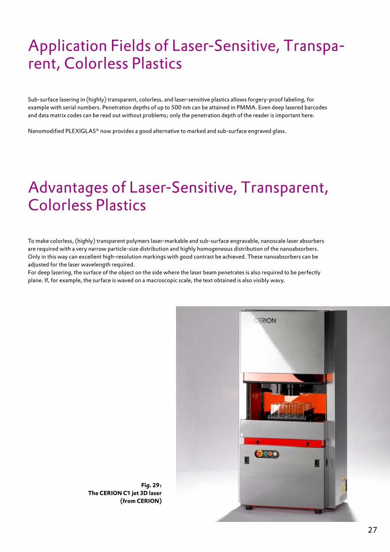
Sub-surface lasering in (highly) transparent, colorless, and laser-sensitive plastics allows forgery-proof labeling, for example with serial numbers. Penetration depths of up to 500 nm can be attained in PMMA. Even deep lasered barcodes and data matrix codes can be read out without problems; only the penetration depth of the reader is important here.
Nanomodified PLEXIGLAS® now provides a good alternative to marked and sub-surface engraved glass.
Fig. 29: The CERION C1 jet 3D laser
(from CERION)
To make colorless, (highly) transparent polymers laser-markable and sub-surface engravable, nanoscale laser absorbers are required with a very narrow particle-size distribution and highly homogeneous distribution of the nanoabsorbers. Only in this way can excellent high-resolution markings with good contrast be achieved. These nanoabsorbers can be adjusted for the laser wavelength required. For deep lasering, the surface of the object on the side where the laser beam penetrates is also required to be perfectly plane. If, for example, the surface is waved on a macroscopic scale, the text obtained is also visibly wavy.
26 27
Application Fields of Laser-Sensitive, Transpa-rent, Colorless Plastics
Advantages of Laser-Sensitive, Transparent, Colorless Plastics

Advantages of Laser-Marking
Fast• Writing speeds of up to 2000 mm/s or 200 characters/s are possible.
Flexible• Layouts can be prepared and stored using standard CAD programs and can be retrieved in any desired order, thus allowing fast changes.
Precise• Even the smallest characters or symbols with very small line thicknesses can be accurately positioned and are clearly legible.
Clean• No additives, and in particular no solvents, are requi-red.
Contactless• Marking is possible not only on smooth, uneven, and textured surfaces and surfaces difficult to access, but also through transparent covers.
Abrasion resistant• Penetration depths of up to 200 μm are possible, so that the marking is both abrasion-resistant and forgery-proof. This is particularly important in regard to product liability.
Transparent• To make colorless (highly) transparent polymers laser processable, nanoscale laser absorbers with very narrow particle-size distribution are required. Only in this way can excellent weld seam quality and high-resolution markings with good contrast be achieved. These nanoabsorbers can be adjusted in accordance with the required wavelength.
Resistant to chemicals• The marking is resistant to cleaning agents, cos-metics, and perspiration with which it comes into contact.
No pretreatment necessary• Because there are no adhesion problems, surfaces can be marked directly, without any special pretreatment.
Low operating costs• Particularly for large runs, the process is highly cost effective. No additional materials are required, and there are no cleaning and disposal costs for colorants or chemicals. Labor costs are eliminated by integrati-on of marking into automatic production processes, and no storage of dies, masks, etc. is needed.
Quality• The process is characterized by a very high degree of reproducibility.
Fig. 30: SEM micrograph line structure
28 29

Laser-Welding of Plastics
Fig. 32: Welding matrix
good welded joint satisfactory welded joint poor welded joint
no welded joint no information available
28 29
Laser welding: Polymer-Compatibility-Matrix
transmittingabsorbing A
BS
ABS
/PA ASA
COC
MA
BS
PA12
PA61
2
PA6
PA 6
-3-T
PA
PACM
12
PA66
PBT
PBT/
ASA PC
PE-H
D
PE-L
D
PEEK
PES
PMM
A
POM
PP PPS
PPSU PS PSU
PTFE
SAN
TPE
ABSABS/PAASACOCMABSPA12PA 612PA6PA 6-3-TPA PACM12PA66PBTPBT/ASAPCPE-HDPE-LDPEEKPESPMMAPOMPPPPSPPSUPSPSUPTFESANTPE
good welding joint medium qualitywelding joint
no joint possible no test bad welding joint
M:\PR_Management_Marl\Teammitglieder\Pienkos\Laserschweissen - Schweissmatrix-Tabelle HPP 05/Polymer-Welding-Matrix kds 06.08.2008 1 - 1
laser beam
weld seamabsorbing polymer
transmitting polymer
Fig. 31: Laser-welding (schematic representation)
Laser-welding of plastics consists in the bonding of thermoplastics under heat and pressure. The bonded surfaces must be in the thermoplastic state. Plastics that can be laser-welded with or without additives are listed in the table below.
The data in the table can vary, depending on the laser wavelength.

Laser-welding of plastics is possible only with fusible polymers; in general, all amorphous and semicrystal-line thermoplastics, as well as thermoplastic elasto-mers (TPU) can be used. Elastomers and thermosets, on the other hand, are not suitable for laser-welding. The fusion temperature regions (Fig. 9) of the plastic parts to be bonded should overlap, and the melts should be mutually compatible. The laser-absorbent join partner should be able, possibly with the use of an additive, to convert the laser energy into heat at the wavelength used.
Degrees of Difficulty in Laser-Welding
The degree of difficulty in laser-welding depends on the laser transparency of the upper and the laser absorption of the lower of the two join partners. The better the upper join partner transmits the laser energy and the better the lower partner absorbs this energy, the easier is the welding process.
The requirements for the procedure increase in the order black, colored, transparent, and white. Appli-cations with a black join partner as the absorber are normally easy to realize or are already available
as standard solutions. Welding of colored plastics requires pigment combinations in laser-transparent and laser-absorbent form. Welding of light colored or transparent plastics is possible by using laser-absor-bing high-performance additives.
di�cult
moderate
easy
transparent/
black
black/
black
color 1/
black
color 1/
color 2
transparent/
transparent
white/
white
color 2/
color 2
30 31
Fig. 33: Degrees of difficulty in laser-welding
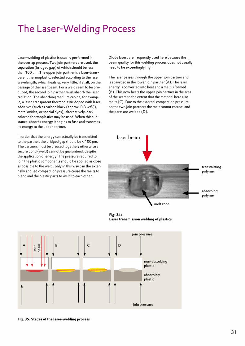
Laser-welding of plastics is usually performed in the overlap process. Two join partners are used, the separation (bridged gap) of which should be less than 100 μm. The upper join partner is a laser-trans-parent thermoplastic, selected according to the laser wavelength, which heats up very little, if at all, on the passage of the laser beam. For a weld seam to be pro-duced, the second join partner must absorb the laser radiation. The absorbing medium can be, for examp-le, a laser-transparent thermoplastic doped with laser additives (such as carbon black (approx. 0.3 wt%), metal oxides, or special dyes); alternatively, dark colored thermoplastics may be used. When this sub-stance absorbs energy it begins to fuse and transmits its energy to the upper partner.
In order that the energy can actually be transmitted to the partner, the bridged gap should be < 100 μm. The partners must be pressed together; otherwise a secure bond (weld) cannot be guaranteed, despite the application of energy. The pressure required to join the plastic components should be applied as close as possible to the weld; only in this way can the exter-nally applied compaction pressure cause the melts to blend and the plastic parts to weld to each other.
The Laser-Welding Process
Fig. 35: Stages of the laser-welding process
A B C D
lase
r be
am
join pressure
join pressure
non-absorbing plastic
absorbing plastic
Diode lasers are frequently used here because the beam quality for this welding process does not usually need to be exceedingly high. The laser passes through the upper join partner and is absorbed in the lower join partner (A). The laser energy is converted into heat and a melt is formed (B). This now heats the upper join partner in the area of the seam to the extent that the material here also melts (C). Due to the external compaction pressure on the two join partners the melt cannot escape, and the parts are welded (D).
30 31
transmitting polymer
absorbing polymer
melt zone
laser beam
Fig. 34: Laser transmission welding of plastics

Tool
Laser beam• Optics•
Weld Seam Quality
Factors affecting weld seam quality in thermoplastics
A structured analysis of a production process is ne-cessary to understand it and develop it further. Every production process is associated with a number of parameters that affect the result of the process. The result in this case is the weld seam between two ther-moplastics. The parameters are of various kinds, and the extent to which they impact the result also varies. The Ishikawa diagram is a useful tool for the structu-ring and analysis of a complex production process in terms of its parameters (see also Fig.36).The main branch of the diagram represents the entire process of laser-welding of thermoplastics, the result being the required quality of the joint.
The entire production process is influenced by certain factors that can be summarized under the heads:
tool (laser beam, laser radiation)• machine• pre- and post processes • material• method, and• people.•
Some of these factors mutually influence one ano-ther. The heads can be further divided into (functio-nal) subheads. The aim is to break down the structure to the extent that all the parameters directly affecting the result of the process are contained in the diagram. For reasons of clarity, the Ishikawa diagram is shown here only (roughly) to the first level of the functional subheads.
Seam quality
Strength• Fastness• Seam width• HAZ• Visual • appearance
Fig. 36: Factors impacting seam quality in laser-welding of thermoplastics (Ishikawa diagram)
Source: Russek, Dr. U.A.:SKZ Seminar, Laser-Welding of Plastics, Würzburg, 2007
32 33
Pre- and post-process
Pre- and post- heat treatment• Coatings• Ambient conditions• Production conditions•
Machine
Traversing system• Type and deflection of beam• Clamping technique• Workpiece handling•
Workpiece
Material• Geometry• Tolerances• Seam accessibility•
Method
Type of radiation• Energy input per unit length• Weld path (with/without)• Post production•
People
Training• Experience• Alertness•

There are four different variants of laser-transmission welding:
contour welding,• simultaneous welding,• quasi simultaneous welding, and• mask welding.•
Laser-Welding Processes
Contour Welding
This method allows the use of low laser power. In contour welding the laser beam traverses the entire join plane of the welding parts, so that relative move-ment of the laser beam and welding part is necessary. This can be achieved by means of a robot, by a traver-sing motion of the laser or the part to be welded. One advantage here is that components with virtually any seam structure can be welded. The welding process is also very flexible, and if the welding part is changed, the traversing movement can be rapidly adjusted for the new weld geometry. This is currently the most widely used process.In the future, quasi simultaneous welding will probably used for relatively small components and contour welding for larger components.
Fig. 37:Contour welding
Fig. 38:Simultaneous welding
32 33
Simultaneous Welding
Simultaneous welding usually uses a diode laser system. The laser beam simultaneously scans the entire joint plane and can heat it with one or more laser pulses. No relative movement between the laser system and welding part is required.Simultaneous welding is highly advantageous for large runs because welding times can be reasonably short. A further advantage is the absence of mecha-nical components such as robot arms and scanners, which require maintenance. Like quasi simultaneous welding, simultaneous welding also allows monito-ring of the process via the setting path; however, the need to adjust the system for each welding part is a disadvantage. The high laser power needed means that several diode lasers may be necessary. Moreover, the system cannot be modified, which means that the same laser cannot be used for slight changes of geometry of the weld seam, or if the components are changed. For reasons of cost, therefore, only components with simple seam geometries are welded using the simultaneous welding process.
Laser head
Laser beam
transmitting polymer
weld seam
absorbing polymer
Laser head
Laser beam
transmitting polymer
weld seam
absorbing polymer

Quasi Simultaneous Welding
In quasi simultaneous welding, the laser beam is guided along the seam using scanner mirrors. There is no movement of either the laser or the join partners; instead, the laser beam is deflected by the moving mirrors. Due to the high speed, the join surface can be traversed several times per second so that, despite the single-point energy source, the surface is heated and plasticized almost simultaneously. Both the join partners are kept under pressure. The advantage of this process it can be used flexibly, and components with three-dimensional seams can also be welded. However, 3D welding is possible only within narrow limits; in this case, a flatfield lens must be used.
A further advantage of quasi simultaneous wel-ding is that higher path speeds are possible than for contour welding. However, higher laser power is also needed than for contour welding for the same energy input per unit length. A disadvantage is that the working space is restricted by the scanner, which limits the maximum geometry of the part. The quasi simultaneous welding process is used mainly for two-dimensional seam geometries. In the future, the technique is expected to find application for relatively small components, and contour welding for larger components.
Mask Welding
In this process, a metallic mask is placed between the laser and the parts to be welded. A laser beam is moved across the mask. The mask has cut-outs wherever welding is required. Areas adjacent to the join surface are covered by the mask. Mask welding allows realization on components of very fine seams that may also lie very close together (< 100 μm apart). Another important advantage of the process is the possibility of producing a variety of weld seam structures on a single component simply by changing the mask. The disadvantage is that at least one mask is necessary. Changes in the seam geometry require the production of a new mask, which results in low flexibility. The areas of application of mask welding include microsystem engineering, electrical enginee-ring, sensors, and medical engineering.
Fig. 39:Quasi simultaneous welding
Fig. 40Mask welding
34 35
laser head
laser beam
transmitting polymer
weld seam
absorbing polymer
deflecting mirror
transmitting polymer
weld seam
absorbing polymer
laser head
laser beam
mask
lens
Application Areas
Laser-welding could replace almost all the classical bonding techniques for plastics, such as adhesion, sealing technology, and ultrasound, vibration, mirror and hot-gas welding.
The miniaturization of components and their incre-asingly complex geometries require weld seams of a fineness that could be achieved with conventional welding methods only with great difficulty, if at all. Laser-welding offers the possibility of even three-dimensional welds in a single workstep. In the pro-duction of sensors for medical engineering, the laser can be used to produce the finest welds within a very restricted space.
The scope of application for plastics depends heavily on the material properties and their compatibility with the laser wavelengths used in various systems. Not all of the currently used thermoplastics absorb laser beams equally well. Special additives developed and patented by Evonik can equip our molding com-pounds for a very wide range of applications.
Components made from these molding compounds offer the advantage of high-quality (transparent/transparent) laser-weldability even with highly transparent and colorless plastics. The High Perfor-mance Polymers Business Line also offers a variety of colored products for non-transparent laser-welding.
Advantages
Advantages of using nanoscale laser absorbers
Colorless, (highly) transparent polymers can be processed using lasers. Excellent weld seam qualities are obtained thanks to the very narrow particle-size distribution of the nanoabsorbers. The nanoabsorbers can be adjusted for the laser wavelength.
Advantages over ultrasound, vibration, mirror, and hot-gas welding, sealing technology, and adhesion
No additional materials, such as adhesives, are necessary. Processing is completely particle-free. No interfering microparticles, adhesive residues, or roughness are produced. Thermal and mechanical stresses on the components are significantly lower. Despite the usually shorter cycle times, the long-term stability and quality of the joints are superior, as are the monitoring options. Lower costs for systems and tools are also an important consideration.
34 35

Laser-Structuring
Increasing miniaturization of components requires ever finer and more accurate tools to produce fine surface structures. The laser, with resolutions of < 1/10 mm, is the ideal tool for such tasks, and splendidly suited to producing the finest structures. It can remove material from plastic surfaces with great precision and selectivity.
Three-dimensional injection molded circuit substra-tes, or 3D MIDs (molded interconnect devices), open up a new dimension, in the true sense of the word, compared with conventional two-dimensional circuit boards, because they offer a high degree of design freedom. A new, laser-supported structuring process (the LDS process, from the company LPKF) for 3D MIDs considerably simplifies the manufacturing
process. It allows, for example, antenna structures to be directly and cost effectively integrated into the housings of cell phones. Furthermore, sophisticated mechatronic systems that integrate mechanical and electrical properties can be realized for applications in automotive construction and medical engineering.
36
Fig. 41: The LDS process, from LPKF
injection molding → structuring → metallizing
thermoplastic released metal nuclei
laser beam precipitated copper(track)

Laser-Sintering
Selective laser-sintering (SLS) is a rapid prototyping process allowing layer-wise production of complex components on the basis of CAD data. This dispenses with the need for a molding tool. SLS is based on the principle of the layer-wise build-up of a structure by application of a polyamide 12 powder followed by selective heating by a laser beam, preferably from a CO2 laser. In general, the process can be characte-rized as follows:
specification of a three-dimensional model in the • form of CAD datano use of molding tools• processing of material in powder form• generative build-up. Molding occurs not by • removal of material, but by applying it.production by layer technology• any desired geometry• no supporting structure necessary•
Fig. 42: Intake manifold for LOTUS sports racing car
36

Requirements on Laser-Processable Molding Compounds
Application Profiles Laser-Marking
Functional marking
Computer keyboards • very good legibility; high abrasion resistance required, due to frequent use
Barcodes on housing parts, electrical • switches, etc.
• one-dimensional barcode • two-dimensional data matrix code Contrast and contour sharpness are important for secure trans mission of coded information.
Information markings
Name and address of producer/ • owner, etc.Equipment type/product data• Operating, setting, connection, • safety, or installation instructions; test symbolsType of voltage supply/power rating • of electrical components or appliancesCircuit diagrams, scales, technical • labels
Decorations
Company logo• Colored symbols and patterns with • transfer film, some directly applicable
Application ProfilesLaser-Welding
Medical technology
Syringes• Hose/tube connectors• Pharmaceuticals packaging• Pouches for liquids• In-line filters• Catheter tips• Balloon catheters• Sensors•
Electrical Engineering
Miniature relay housings• Dust- and water-tight housings for • electronic components
Requirements on Laser-Wor-kable Molding Compounds
Automotive engineering
Front headlamp casing with reflector• Rear lamp casing with reflector • Dust- and water-tight housings for • electronic componentsElectronic ignition key • (remote control)
Requirements ProfileLaser-Structuring
Electronics
Tracks for MIDs•
Medical Engineering
Microfine channels in biosensors•
38 39
Laser Additives
Additives for Non-Transparent Mol-ding Compounds
In addition to high contrast, adequate staining depth and a surface as smooth as possible are also required. The intensity of the color change reaction increases with the content of laser-sensitive pigment, but the penetration depth of the laser radiation decreases simultaneously. For a low content, the penetration depth is very high, but the expected contrast is too low.
The contrast increases with increasing laser • intensity.The staining depth is reduced with increasing • laser intensityThe foaming height (which is a measure of the • quality of the surface) increases with increasing intensity; a smooth surface is desired.
For the same quality of marking, the surface does not foam to the same extent when an additive is used, and is therefore more resistant to abrasion.To ensure excellent marking, we have taken these effects into account in developing a laser additive that does not affect the coloration.
Laser-welding requires high weld seam strength. This should ideally attain the strength of the welded components.For a good weld to be obtained, a laser-sensitive additive must be compounded into the absorbing join partner. The classic laser additive for this purpose is carbon black. If, however, the same coloration is required for the upper and lower join parts, color pigments or metal oxides adjusted for the laser wavelength can be used.
If plastics are to be laser-structured at the surface, for example, with CO2 lasers, the use of additives is not absolutely necessary. Special molding compounds are required for production of three-dimensional circuit substrates with miniaturized track structures, for example, for insertion of MID components. The laser additive contained in these offers, after laser-structuring, the possibility of selective deposition of copper for the tracks.
Additives for (Highly) Transparent, Colorless Molding Compounds
With the special additives developed and patented by the Inorganic Materials Business Unit of Evon-ik, our (highly) transparent and colorless molding compounds can be equipped for the most diverse applications.The laser additive has practically no impact on the haze of the plastics used. These molding compounds are therefore also highly suitable for deep lasering of markings or lasering of 3D CAD objects.
The laser additives ensure high-quality laser-weld-ability, even with colorless, transparent-transparent joins.
38 39

Laser-Processable Molding Compounds
40 41

40 41

Laser-Processable Semifinished Products
1) = Produced by Nd:YAG laser (1064 nm) 2) = Product with relatively high tracking resistance HDT = Heat deflection temperature, Method B, 0.45 Mpa HI = increased impact strengthC = Contrast, depends on the luminance of the color GF = glass fiber contentLV = low viscosity P = plasticizedMV = medium viscosity CF = carbon fiber contentHV = high viscosity FC = filler mix of equal parts of graphite, carbon fibers, and PTFEFR = contains flame retardantN = no breakP = partial breakC = complete break
In addition to the compounds listed above, other variants, such as compounds of the VESTAMID® E Series (PEBA), can be supplied in laser-processable form.
42 43

Environmental Aspects
Emissions
In industrial laser systems, the small amounts of gase-ous decomposition products that can be generated by the heat developed during laser-processing are drawn off by exhaust systems. The high efficiency achieved through the use of special additives in laser-pro-cessable molding compounds from Evonik makes the processes even more eco-friendly. The advantage is obvious: if the required contrast or fusion is achieved with less laser energy, fewer decomposition products are generated.
Recycling
All the laser-processable industrial plastics from Evo-nik listed here can be recycled without any problem. Sprues and unmarked moldings can be returned directly to the primary process as regrind. Only recy-cled materials from parts already marked should be used for a secondary application, due to their possible discoloration.
QualityThe High Performance Polymers Business Line of Evonik is EN ISO 9001:2000 and ISO/TS 16949:2002 certified, and therefore formally recognized as a reliable supplier.
Our products set high quality standards in the market. We offer you customized solutions specially tailored to your requirements profile.
42 43

Future Prospects
Wear resistance and protection against forgery are aspects that will promote the spread of laser-marking systems. Whether for product liability or future recycling of finished parts, laser-inscribed quality-relevant or production data leave no doubt as to the origin of a molding. Producer, production dates, machine numbers, and material batches can all be easily recorded.
For very small part geometries, the compact data matrix code (DMC) is the ideal solution; with the ongoing miniaturization of components, this will be the data code of the future. It encodes the data in the matrix both horizontally and vertically, so that thousands of items of information can be recorded on the smallest surfaces. In addition it is possible to mark data in private mode, which can be read only with the correct access authorization.
The use of the laser-marking and data matrix code technologies on suitable materials from our product range (see the tables on pages 40 to 42) allows product identification with an extremely high degree of security which practically eliminates the risk of substitution errors.
Laser-welding of polymers is still a relatively new joi-ning technique. But in a number of sectors it is already well on the way to replacing conventional joining process such as ultrasound, vibration, mirror, and hot
gas welding, sealing technology, and adhesion.Compared with conventional methods, however, laser-welding currently involves significantly higher investment costs.In medical engineering, a particle- and emission-free working environment is very important. Medical sensors consist of components that are getting increasingly smaller, with complex joint geometries. The flexibility and speed with which even compli-cated weld seams can be produced and high quality standards are the outstanding properties of the laser-welding process.
Similar observations apply for electrical engineering. Tiny housings for fully encapsulated miniature relays and electronic components must be laser-welded because only this method ensures clean processing without generating particles that interfere with the mechanics or electronics.
In the automotive industry, headlamp and rear lamp casings are already being laser-welded. The partially three-dimensional geometries do not permit of any other joining technique.
With the increasing use of plastics in automotive con-struction, new, fast, and flexible joining techniques are required that also meet the highest quality stan-dards. No other joining technique currently satisfies these requirements as well as laser-welding.
44 45

Classes of Lasers
Laser devices are divided into classes depending on the biological effects of the laser radiation. Specification of the limit values up to which no damage is expected is of major importance for nationally and internationally defined laser classes. In addition to the U.S. ANSI stan-dard, the International Commission on Non-Ionizing Radiation Protection has published limit values in the spectral region between 400 and 1400 nm.
The limits are defined primarily in terms of thermal power and non-ionizing radiation. Due to the optical focusing properties of the eye, the hazard increases in the visible spectral range. In the invisible range, there is an adjacent region in which the eye is still well focused and transparent.
DIN EN 60825-1 ClassificationLasers are divided into equipment classes depending on the hazard to humans. The DIN EN 60825-1 classi-fication is specified by the manufacturer. (The old DIN VDI 0837 classification may no longer be used for new lasers.)
Laser Class Description
Laser Classes
Fig. 43: Laser safety classes as defined in DIN EN 60825-1
*) Note on laser classes 2 and 2M: Scientific studies (at the FH in Cologne) have shown that the blink reflex (which occurs within 0.25 s; longer exposure damages the eye) occurred in less than 20 percent of the test subjects. The existence of the blink reflex for protecting the eye should not therefore be taken for granted. If laser radiation of class 2 or 2M enters the eye, the eyes should be deliberately closed or immediately averted. It must also be noted that the blink reflex occurs only with visible light. Laser radiation in the infrared range, for example, does not cause blinking because the radiation is not detected by the eye. Special care must therefore be exercised with invisible laser radiation.
44 45

Literature and Sources
Bundesamt für Arbeitsschutz und Arbeitsmedizin (BAuA): BAuA-Broschüre „Damit nichts ins Auge geht... - Schutz vor Laserstrahlung“, 1. Auflage. Dortmund, 2006.BAuA-Forschungsbericht Fb 985 „Überprüfung der Laserklassifizierung unter Berücksichtigung des Lidschlussreflexes“
Berufsgenossenschaft der Feinmechanik und Elektro-technik (BGFE): „Die neuen Laserklassen Laserklassen nach DIN EN 60825-1“ „Unfallverhütungsvorschrift „Laserstrahlung“ (BGV B2/VBG 93)
Bayerisches Laserzentrum (BLZ), Erlangen
BASF: Technische Information für Experten 02/00 – Laserstrahlschweißen von Kunststoffen im Durch-strahlverfahren, Broschüre, 2000
Becker/Braun: Kunststoff Handbuch (1 Die Kunst-stoffe; 3/4 Polyamide), Hanser Verlag
Carl BAASEL Lasertechnik GmbH & Co. KG, Starn-berg: Laser zum Beschriften, Schneiden, Schweißen, Mikrostrukturieren und Perforieren
CERION GmbH, Minden: Lasersysteme für die 3D-Laserinnengravur
Dietel, C.: Laserstrahlbeschriften von Kunststoffen - eine Übersicht, Vortrag BLZ, München, 2006
Donges, A.: Physikalische Grundlagen der Lasertech-nik. 2. Auflage. Hüthig, Heidelberg 2000
Franck, A.: Kunststoff-Kompendium, Vogel Buchver-lag, 6. Auflage 2006
Fraunhofer Institut für Lasertechnik (ILT), Aachen
Gebert K.; Hopfner M..; Laserschweißen von Kunst-stoffen, SKZ Vortrag, Würzburg, 2004
Hänsch, D.: Die optischen Eigenschaften von Polymeren und ihre Bedeutung für das Durchstrahl-schweißen mit Diodenlaser, Dissertation, Aachen, 2001
Hillmann, R.: Kunststoffbeschriften mit Lasern un-terschiedlicher Wellenlänge, Vortrag BLZ, München, 2006
Hopfner M.: Laserschweißen von Kunststoffen, Vor-trag Allod Werkstoff GmbH, Burgbernheim, 2004
Klein, M.: Laser Beam Welding of Plastics in Micro Technology, Dissertation, Köln, 2001
Klein, R.M.: Bearbeitung von Polymerwerkstoffen mit infraroter Laserstrahlung, Dissertation, Aachen, 1990
Kneubühl, F.K., Sigrist, M.W.: Laser, 6. Auflage. Teubner (Teubner Studienbücher Physik), Wiesba-den 2005
Korte, J.: Laserschweißen von Thermoplasten, Dissertation, Paderborn, 1998
Leitfaden „Laserstrahlung“, Fachverband für Strah-lenschutz e.V.
Liebscher, J.: Beidseitig gleichzeitiges Laserstrahl-schweißen von großformatigen 3D-Luftfahrtstruktu-ren, Fraunhofer Institut für Werkstoff- und Strahl-technik (IWS), Dresden, 2005
46 47

LPKF Laser & Electronics AG, Garbsen/Erlangen: Lasersysteme/-verfahren für die Laser-Direktstruk-turierung, Laserschweißsysteme
Meyers Lexikon online 2.0
N.N : Einflußgrößen beim Schweißprozess, Vortrag SKZ, Würzburg, 2006
N.N : Grundlagen Laser, SKZ, Würzburg, 2006
N.N : Grundlagen Laserkunststoffschweißen, Vortrag SKZ, Würzburg, 2006
N.N : Kunststoff-Fügeverfahren, Vortrag, Würzburg, 2006
N.N.: Lasertechnik CD-ROM mit Bildern zur Vorle-sung Lasertechnik 1 und 2, Lehrstuhl für Lasertech-nik, RWTH Aachen, 1998
N.N: Grundlagen Laser-Kunststoffschweißen, Vortrag BLZ, Erlangen, 2006
N.N: Kunststoff-Fügeverfahren, Vortrag BLZ, Erlan-gen, 2006
Oberbach , K.: Saechtling – Kunststofftaschenbuch, 28. Auflage, Hanser Verlag 2001
Pösentrup R.; Stier T.; Werkstoffe für das Laser-schweißen, SKZ Vortrag, Würzburg, 2004
Potente, H.; Fiegler, G.: Technische Aspekte des Laserschweißens von Kunststoffen, SKZ Seminar, Würzburg, 2004
Potente, H.; Heil, M; Korte, J.: Laserschweißen von Thermoplasten, Plastverarbeiter 46 (1995) 9
Russek, Dr. U.A. (Huf Tools GmbH, Velbert): Para-meteränderungen beim Laserdurchstrahlschweißen von Thermoplasten und deren Auswirkungen auf die Schweißnaht, Vortrag SKZ, Würzburg, 2007
Schulz J-E.: Material, Process and Component Investigations at Laser Beam Welding of Polymers, Dissertation, Aachen, 2002
Siefert, M.; Renner, T.: Laser-adapted construction for plastic welding, Kunststoffe 2/2004, 2004
Siegman, A.E.: Lasers; University Science Books, Mill Valley/CA 1986
Struve, B.: Laser, Grundlagen, Komponenten, Tech-nik, 11. Auflage, Verlag Technik, Berlin 2001
TREFFERT GmbH & Co.KG, Bingen: Masterbatche und Compounds mit Laseradditiven
William T.: Silfvast: Laser Fundamentals, 2. Auflage, Cambridge University Press, Cambridge 2004
Wolff, W.: Permanently Mark Highly Transparent Plastics, Kunststoffe plast europe 09/2005
Wolff, W.: 3D Laser Subsurface Engraving, Kunst-stoffe plast europe 12/2005
46 47

This information and all technical and other advice are based on Evonik’s present knowledge and experience. However, Evonik assumes no liability for such information or advice, including the extent to which such information or advice may relate to third party intellectual property rights. Evonik reserves the right to make any changes to information or advice at any time, without prior or subsequent notice. EVONIK DISCLAIMS ALL REPRESENTATIONS AND WARRANTIES, WHETHER EXPRESS OR IMPLIED, AND SHALL HAVE NO LIABILITY FOR, MERCHANTABILITY OF THE PRODUCT OR ITS FITNESS FOR A PARTICULAR PURPOSE (EVEN IF EVONIK IS AWARE OF SUCH PURPOSE), OR OTHERWISE. EVONIK SHALL NOT BE RESPONSIBLE FOR CONSEQUENTIAL, INDIRECT OR INCIDENTAL DAMAGES (INCLUDING LOSS OF PROFITS) OF ANY KIND. It is the customer’s sole responsibility to arrange for inspection and testing of all products by qualified experts. Reference to trade names used by other companies is neither a recommendation nor an endorsement of the corresponding product, and does not imply that similar products could not be used.
(July 2011)
Contact Person
Rainer Göringphone +49 2365 49-4394rainer. [email protected]
Evonik Industries AGHigh Performance Polymers Paul-Baumann-Str. 145772 Marl/Germany
phone +49 2365 49-6322fax +49 2365 49-806322www. evonik.com/performancepolymers


![ResearchArticle Polymer ...downloads.hindawi.com/journals/amse/2018/3984835.pdfthermoplastic polymers that form continuous lms of polymer when dehydrated [16, 17]. e latex polymers](https://static.fdocuments.us/doc/165x107/5ecbc580aab05a781359c0e8/researcharticle-polymer-thermoplastic-polymers-that-form-continuous-lms-of-polymer.jpg)