POLYMERS HELP DELIVER A SOLAR FUTURE …€¦ · june/july 2012 polymers help deliver a solar...
7
June/July 2012 POLYMERS HELP DELIVER A SOLAR FUTURE EUROPE’S TOP 50 PE FILM EXTRUDERS BENEFITS OF WATER-COOLED BLOWN FILM OUTLOOK FOR HEAVY DUTY PLASTIC SACKS
-
Upload
phamnguyet -
Category
Documents
-
view
213 -
download
0
Transcript of POLYMERS HELP DELIVER A SOLAR FUTURE …€¦ · june/july 2012 polymers help deliver a solar...
June/July 2012
POLYMERS HELP DELIVER A SOLAR FUTURE
EUROPE’S TOP 50 PE FILM EXTRUDERS
BENEFITS OF WATER-COOLED BLOWN FILM
OUTLOOK FOR HEAVY DUTY PLASTIC SACKS

www.filmandsheet.com June/July 2012 | film & sheet eXtRUsiON 29
Water-cooling for blown film | process feature
Using water, rather than air, to cool blown film can create products with superior properties. Robert Armstrong, I-Hwa Lee and Karen Xiao explain some of the advantages
Water cooling of co-extruded blown film can create
differences in key physical properties, compared to
those produced using conventional air cooling, as we
have discovered through conducting a recent study.
the physical properties we have evaluated include
optics, barrier to oxygen and moisture, resistance to
biaxial deformation and a qualitative evaluation of
thermoformability on a typical horizontal form-fill-seal
(hffs) machine. We also looked at the effect of varying
water quench process parameters, such as water ring
position, water temperature and annealing temperatures.
the properties of water-quenched (WQ) films are
quite different to the air-quenched (AQ) films produced
by a typical upward blown film process. WQ films had
lower resistance to orientation, improved thermoform-
ability across a range of temperatures and reduced
haze, for example.
Our study was separated into three distinct parts.
Part i dealt with the properties of flat films; Part ii with
thermoformability; and Part iii with the orientability of
the films.
Downward coolingless than a decade ago, Brampton engineering
commercialised a new cooling system for blown film
applications in which the film is extruded downwards
and quenched using water instead of air – which
introduces different morphology into the film structure.
What is unique in this process is that the film is
quenched almost as soon as it passes through a water
ring. Once the film is cooled, it is still collapsed and
wound. the water-quench system minimises the time
Water-cooling brings benefits
to blown film
film & sheet eXtRUsiON | June/July 2012 www.filmandsheet.com30
process feature | Water-cooling for blown film
that the polymer melt spends in the crystal-growth
temperature range.
the crystallisation structure of films produced this
way will be very different. A ‘slowly cooled’ crystal
structure (typical of air quenching) is quite different to a
‘rapidly cooled’ crystal structure (from water-quench-
ing). Because very little time is spent in the ‘crystal-
growth’ temperature range, the film becomes much
more amorphous. the downward-extruded, water-
quenched system is a unique process that combines the
advantages of cast and conventional blown film
processes: it retains the improved clarity and thermo-
formability, and reduced curl of a cast film process; and
it also keeps the balanced orientation and the process
flexibility of a blown film process. this system has also
given blown film processors opportunities to use less
expensive resins to achieve the same or superior
properties. for example, in a typical thermoforming
structure, processors would commonly use a copolymer
polyamide or amorphous polyamide to improve
thermoformability and clarity. in a water-quench
process, these more expensive copolymers can be
reduced or eliminated completely.
Film structuresthe oxygen barrier and physical properties of co-extrud-
ed 100 micron, nine-layer structures were directly
compared using both a WQ and AQ co-extrusion process.
(the structures are shown in Table 1 on page 34.)
the materials used include a polyamide 6, a 38 mol%
ethylene-vinyl alcohol (eVOh-1), a modified 32 mol%
eVOh (eVOh-2), an octene-llDPe with a melt index of 1
and 0.918 g/cm3 density, a maleic anhydride-modified
Pe, and a polyolefin plastomer with a melt index of 1
and a 0.902 g/cm3 density.
the first structure (structure A) is a symmetric PA/
eVOh/PA co-extrusion and the second structure
(structure B) is an asymmetric co-extrusion with a
polyamide skin layer. for structure A and B, all materi-
als used in each structure were the same polymer from
the same production lot, so observed differences in
physical properties are directly related to the quenching
process. the third structure (structure C) is a symmetric
Pe/eVOh/Pe co-extrusion, with the eVOh either being a
38 mol% (eVOh-1) or a modified 32 mol% eVOh
(eVOh-2) which was expected to have lower resistance
to orientation than conventional 32 mol% eVOh. in all
cases the total thickness of the films was 100 microns.
Equipment and procedurestwo 9-layer Brampton engineering blown film lines
were used in the study. Both consisted of 9-layer stacked
co-extrusion dies (sCD). the AQ line had two 2.5in
(63.5mm) and seven 2in (50.8mm) extruders, while the
water-quench line had nine 2.5in (63.5mm) extruders.
the AQ line has a standard internal bubble cooling (iBC)
system, while the WQ line has a water-cooling ring on
the outside of the bubble. Both lines also consisted of
Figure 3: Oxygen barrier OF FlaT Films
Figure 2: WaTer vapOur barrier OF FlaT Films
Figure 1: Haze OF FlaT Films
20
18
16
14
12
10
8
6
4
2
0
AQ
WQ
Haz
e (%
)
Structure A Structure B
15.5
4.1
17.8
7.4
Structure A is PA/EVOH/PA core with PE skinsStructure B is PA/EVOH/PA core with PA skin
90
80
70
60
50
40
30
20
10
0
AQ
WQ
WVT
R (m
g-m
m/[
m2 .d
ay])
Structure A
Structure A is PA/EVOH/PA core with PE skinsStructure B is PA/EVOH/PA core with PA skin
Structure B
40
63.6
51.6
80.2
16
14
12
10
8
6
4
2
0
AQ
WQ
AQ
WQ
OTR
(cc-
20um
/[m
2 .day
])
Structure A
20˚C/65%RH
30˚C/85%RH
Structure B Structure A Structure B
Structure A is PA/EVOH/PA core with PE skinsStructure B is PA/EVOH/PA core with PA skin

Water Quenched Blown Barrier FilmWith more 7 – 11 layer blown film installations worldwide than any other company, Brampton Engineering (BE) is the established world leader in barrier film coextrusion systems. BE’s conventional air cooled and AquaFrost® water quenched blown film lines operate in every continent producing barrier films used in food, medical and industrial packaging.
AquaFrost® lines deliver the clearest, softest, strongest and best thermoformable films in the market for the most demanding packaging applications. Available in up to 11 layers for maximum processing flexibility and successfully proven in markets worldwide for over 10 years, AquaFrost® is the original name for water quenched blown barrier film technology.
AquaFrost ®
11 -layer
PA
Tie
LLDPE
Tie
PA
EVOH
PA
Tie
PP
Tie
mLLDPE
Brampton Engineering Inc.World Leader in Blown Film Innovation 8031 Dixie Road, Brampton, ON L6T 3V1 Canadawww.be-ca.com

film & sheet eXtRUsiON | June/July 2012 www.filmandsheet.com32
process feature | Water-cooling for blown film
standard oscillating haul-off systems and double turret
winders for winding the films. Both die diameters were
450mm and the experiments were performed at 450kg/
hr or 1kg/hr/mm die circumference. the process
parameters investigated included water ring position,
water temperature and annealing temperature.
Batch forming tests were conducted using a ZeD
batch thermoformer (batch former), with eight samples
taken for each film condition. Draw depth was at 4cm
with a corner radius of 0.6cm. the oxygen transmission
rate (OtR) was then measured for each formed package.
for each package, the inside was purged with nitrogen.
the package was also controlled so that the relative
humidity (Rh) was 65% on the outside of the package
and 100% on the inside. the concentration of oxygen
inside the package was then measured over time.
in the multivac horizontal thermoformer (hffs
former) trials, the film was heated by both a top plate
and a bottom plate. in this experiment, the tempera-
tures of both plates were kept equal. the width of the
film was 325mm and either two or four pockets were
formed per set across each web. the bulk of the work
was conducted with the deeper draw four pocket
set-up, with the dimensions of 135mm x 125mm x
85mm. the heating time was kept at 1 second with 2
seconds of forming time while the temperature of the
heating plates was varied to identify the optimal
thermoforming window.
the instrumented biaxial orientation tests were
conducted using a Bruckner lab scale instrumented
biaxial orientation unit. film samples were prepared as
100mm x 100mm square sheets that were mounted in
the unit using same machine direction (mD) and
transverse (tD) orientation for all specimens. After
establishing conditions that allowed for orientation to
more than 3 x 3 ratio, all film samples were tested after
preheating at 100°C for 20 seconds. the orientation
speed was 1m/min in both the mD and tD. five repli-
cates of each film sample were oriented to 2 x 2 for
oxygen barrier testing. An additional three replicates
were tested to 3 x 3 orientation to determine the
resistance to deformation of each structure under
conditions that simulated the thermoforming process.
Data was collected every 0.1s from the time the test was
initiated. Key data was time and force in both mD and
tD. from the time and force data a set of stress-strain
and total stress-draw ratio results was calculated.
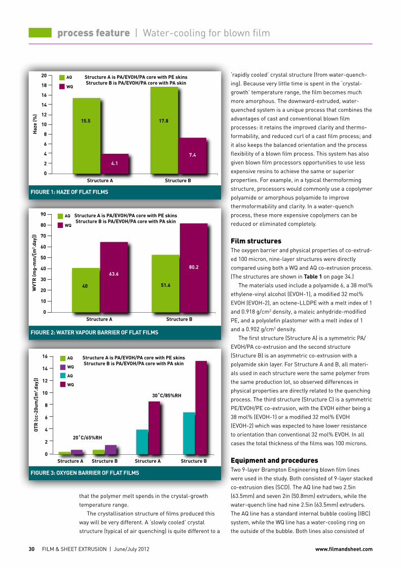
Flat film propertiesin Part i of the study, an evaluation of the haze, moisture
vapour barrier and oxygen barrier of flat films was
conducted. the overall lower haze – due to lower
crystallinity of the WQ structures – should also result in
lower barrier properties, and this is what has been
observed. films obtained from the AQ process gave lower
values of water vapour transmission (WVtR) in both the
symmetric and asymmetric structures. the OtR values
show a similar trend. the oxygen barrier was measured
under two sets of conditions: one with 65% relative
humidity (Rh) at 20°C and the second one with 80% Rh at
30°C. the difference in the OtR is magnified at the higher
Rh and temperature condition. As expected, the WQ films
gave higher OtR values – indicating a decrease in barrier
properties, compared to AQ films.
to investigate the effect of process conditions on the
final film properties, films were also obtained at various
water temperatures, water tank positions and annealing
temperatures. insignificant changes in OtR values were
seen, indicating that the process conditions have a minor
effect on the final film properties. Optical microscopy
and Wide-Angle X-Ray Diffraction (WAXD) analysis was
performed to qualitatively determine the difference in
crystalline structure of the AQ and WQ samples. the
results of this analysis indicated that the polyamide,
eVOh and Pe in the AQ samples has a higher degree of
crystallinity than their WQ counterparts.
(Figure 1 shows the haze comparison for the
different film structures using the WQ and the AQ
methods, while Figure 2 and Figure 3 show the water
vapour transmission rates and oxygen transmission
rates respectively. All three are on page 30.)
Thermoforming resultsPart ii of the study looked at the forming characteristics
of AQ and WQ structures. the oxygen barrier of the
formed package of the WQ film is slightly lower than
that of the AQ packaging, indicating that the WQ film
has better thermoformability than the AQ film – so the
Water-cooling
extrudes
the film
downwards,
rather than
upwards

film & sheet eXtRUsiON | June/July 2012 www.filmandsheet.com34
process feature | Water-cooling for blown film
formed package of WQ film is better able to retain its
barrier properties. it is also worth noting that the shape
of the formed package from the WQ film was more
appealing than that of the AQ film, again confirming the
better package integrity.
three criteria were used to determine the formability
of the film on the multivac as a function of temperature:
depth and quality of the pocket or cavity draw; number
of cavities formed; and, the degree of cavity breaks. for
cavities that did form to full depth, a gauge distribution
across the pocket cross-section was measured.
Consistent with lower crystallinity, the WQ technology
allows barrier films to form more evenly at lower
forming temperatures, and over wider temperature
windows, than AQ films of the same construction. this
has been seen for nylon-encapsulated eVOh barrier
films with llDPe as the outer layers, and for nylon-
encapsulated eVOh barrier films with one outer layer of
PA6. the overall gauge distribution was more uniform,
and the thinnest areas at the corners and base of the
formed container were heavier for the WQ films than the
AQ films, because of the lower temperature forming that
is possible with water quenching. typically, the thinnest
areas are 12-15 microns when formed at 95-120°C, and
5-10 microns when formed at or above 130°C.
there were differences in gauge distribution of
formed cavities for films made by the two different
quenching methods. it was found that, for deep-draw
thermoforming applications, it would be necessary to
encapsulate eVOh with nylon. for air-cooled films with
the different barrier configurations, only nylon-encap-
sulated eVOh films showed a forming window with
temperature on the hffs former. the non-encapsulat-
ed eVOh films could not form, since 50% or more of the
cavities did not form or formed with breaks and film
blow-outs. the gauge distribution of the formed cavities
also showed that the corners and base were noticeably
thinner for the non-encapsulated eVOh films compared
to the nylon-encapsulated eVOh films.
Draw ratiosfor part iii of this study, three film structures (A, B and
C) were oriented to the same draw ratio at the same
strain rate under constant condition of preheating time
and temperature that allowed for orientation of all
samples. the preheating temperature of 100°C was
consistent with the lower operating temperature of both
the batch former and the hffs former. the preheating
time of 20 seconds was considerably longer than the
preheating time of the hffs former, but similar to that
of the batch former.
the oxygen barrier of the films oriented to 2 x 2 ratio
from 100 microns was evaluated using mocon 2/20 or
2/21 units at the elevated temperature and humidity
condition of 30°C and 85% Rh to magnify differences in
oxygen barrier caused by crystallinity of the polyamide
and eVOh.
the orientability (or resistance to deformation) of the
samples was evaluated by comparing the engineering
stress and strain curve, and more specifically the stress
at yield point and maximum stress. As a measure of
total resistance to deformation the total stress versus
draw ratio was estimated, and the modulus of tough-
ness (strain energy in deformation) was calculated
through to the target draw ratio of 3x3. (the key results
of the biaxial orientation tests, including the estimated
modulus of resilience and modulus of toughness for
each structure, are seen in Table 2 on page 36.)
Deformation resistancefor structure A, resistance to deformation of the AQ
blown films was higher than the WQ films, as shown by a
higher stress at yield point and higher ultimate stress.
the total stress and the modulus of toughness was also
higher throughout orientation. Resistance to orientation
was greater in the mD than the tD for both methods.
there was an overlap between the mD resistance of the
WQ structure, and the tD resistance of the AQ structure.
the structure B films replicated the results of
Table 1: Experimental structures of 9-layer filmsStructure Layer 1 Layer 2 Layer 3 Layer 4 Layer 5 Layer 6 Layer 7 Layer 8 Layer 9
A Pe Pe t PA eVOh-1 PA t Pe Pe
thickness (%) 15 8 8 15 8 15 8 8 15
B P t PA eVOh-1 PA t Pe t PA
thickness (%) 15 10 10 8 10 8 14 10 15
C Pe Pe Pe t eVOh-1 t Pe Pe Pe
thickness (%) 13 15 8 10 8 10 8 15 13
PA = polyamide 6EVOH-1 = 38mol% ethylene-vinyl alcoholEVOH-2 = a modified 32mol% EVOHPE = octene-LLDPET = maleic-anhydride modified PE P = polyolefin plastomer
structure A is PA/eVOh/PA core with Pe skins
structure B is PA/eVOh/PA core with PA skin
structure C is Pe/eVOh/Pe

film & sheet eXtRUsiON | June/July 2012 www.filmandsheet.com36
process feature | Water-cooling for blown film
structure A, with the total resistance to deformation,
stresses and modulus of toughness all being higher for
the AQ samples. Within the B sample set there were no
significant differences between samples, which is
consistent with results of the Part ii forming trials.
the structure C samples (eVOh-1 and eVOh-2)
oriented with similar characteristics – namely a low
resistance to deformation that was significantly lower
than both the structures containing nylon (A and B). the
Pe/eVOh/Pe structure C without nylon also exhibited
quite different resistance to orientation in the mD and
tD directions and also evidence of fibrillation of the
eVOh and/or Pe as variation in stress as orientation
progressed was much more dramatic than that
observed in orientation of the nylon containing films.
the oxygen barrier after orientation of the films was
evaluated under the worst case conditions of 30°C/85%
Rh to magnify any differences in barrier. the raw OtR
results were normalised to a value of permeability in
cc.20microns/m2.day at 30°C and 85% Rh (see Table 3).
the barrier of all films after orientation became quite
similar, with the barrier of the AQ films becoming lower
or the same and the WQ films becoming higher. this
suggests that the heating and then orientation of the
films created conditions of annealing, then strain-
induced crystallisation, that tended to produce similar
morphologies and thus barrier of the oriented films.
this would be consistent with the findings of the
forming and formed package barrier testing, which
showed the WQ films had superior characteristics and
barrier after forming due to higher average thickness
and less gauge variation.
Conclusionin the final part of the study, resistance to orientation of
the two films was compared. the WQ films had lower
resistance to orientation than the AQ films, which
explains the ability to thermoform the WQ films at a
lower temperature and achieve a more uniform gauge
distribution. this attribute, particularly the higher
corner and base thicknesses of the formed packages,
resulted in higher barrier properties for WQ films after
forming, even though the AQ films had higher oxygen
barrier in the unformed state.
these results are consistent with the lower crystalline
structures of the WQ films seen in Part i of the study.
the ability of nylon to improve the orientability of
eVOh was confirmed, with evidence that nylon prevents
fibrillation of eVOh (seen during biaxial orientation of
the structure C Pe/eVOh/Pe films). the properties of
the WQ films was quite different from the AQ films, with
the WQ films having lower resistance to orientation,
improved thermoformability across a range of tempera-
tures and reduced haze.
Conversely, the barrier of the WQ films to oxygen and
moisture was lower than that of the air quenched films
before forming.
the observed difference in key physical properties
was correlated with variation in polymer crystallinity
between the WQ and AQ films using optical microscopy
and WAXD.
the results of barrier testing of oriented films and
formed packages suggest that orientation at tempera-
tures below the recrystallisation temperature of the
eVOh tends to equalise crystallinity of the eVOh – and
thus the effective oxygen barrier of formed packages
becomes a function of average thickness and localised
variation in thickness of the eVOh layer, rather than the
original extrusion process.
About the authorsRobert Armstrong is at Kuraray America; i-hwa lee is at DuPont; and Karen Xiao is at Celgard – but was formerly at Brampton engineering.
Table 3: Oxygen permeability before and after orientation (30°C/85%RH)Structure A A B B C C
extrusion Process AQ WQ AQ WQ eVOh-1 eVOh-2
Unoriented 4.0 8.6 6.8 15.2 4.4 3.1
Oriented 6.2 6.5 7.0 6.2 4.1 4.2
Table 2: Summary of biaxial orientation test results (3 x 3 draw ratio at 100°C)Structure A A B B C C
extrusion Process AQ WQ AQ WQ eVOh-1 eVOh-2
Yield stress (mPa) 12.2 8.0 18.0 10.5 3.5 1.3
Ultimate engineering stress (mPa) 29.3 24.8 39.4 28.8 7.9 8.3
modulus of resilience (mPa) 0.96 0.43 1.1 0.64 0.20 0.17
modulus of toughness (mPa) 39.4 29.4 57.2 35.5 13.0 12.6


![Review Article Edible Polymers: Challenges and OpportunitiesJournal of Polymers T : Water vapor permeability (WVP) properties of di erent polymers [ ]. Film formulation WVP (gm 1s](https://static.fdocuments.us/doc/165x107/60ac9618de1e6c714e72a8c9/review-article-edible-polymers-challenges-and-opportunities-journal-of-polymers.jpg)