Polymer Materials and their · PDF filePoly(vinyl butyral) PVB Poly(vinyl chloride) ... Figure...
48
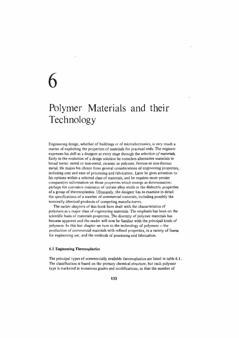
6 Polymer Materials and their Technology Engineering design, whether of buildings or of microelectronics, is very much a matter of exploiting the properties of materials for practical ends. The engineer expresses his skill as a designer at every stage through the selection of materials. Early in the evolution of a design solution he considers alternative materials in broad terms: metal or non-metal, ceramic or polymer, ferrous or non-ferrous metal. He makes his choice from general considerations of engineering properties, • including cost and ease of processing and fabrication. Later he gives attention to his options within a selected class of materials, and he requires more precise comparative information on those properties which emerge as determinative: perhaps the corrosion resistance of certain alloy steels or the dielectric properties of a group of thermoplastics. Ultimately, the designer has to examine in detail the specifications of a number of commercial materials, including possibly the nominally identical products of competing manufacturers. The earlier chapters of this book have dealt with the characteristics of polymers as a major class of engineering materials. The emphasis has been on the scientific basis of materials properties. The diversity of polymer materials has become apparent and the reader will now be familiar with the principal kinds of polymers. In this last chapter we turn to the technology of polymers — the production of commercial materials with refined properties, in a variety of forms for engineering use, and the methods of processing and fabrication. 6.1 Engineering Thermoplastics The principal types of commercially available thermoplastics are listed in table 6.1. The classification is based on the primary chemical structure, but each polymer type is marketed in numerous grades and modifications, so that the number of 153
Transcript of Polymer Materials and their · PDF filePoly(vinyl butyral) PVB Poly(vinyl chloride) ... Figure...
6
Polymer Materials and theirTechnology
Engineering design, whether of buildings or of microelectronics, is very much a
matter of exploiting the properties of materials for practical ends. The engineer
expresses his skill as a designer at every stage through the selection of materials.
Early in the evolution of a design solution he considers alternative materials in
broad terms: metal or non-metal, ceramic or polymer, ferrous or non-ferrous
metal. He makes his choice from general considerations of engineering properties, •
including cost and ease of processing and fabrication. Later he gives attention to
his options within a selected class of materials, and he requires more precise
comparative information on those properties which emerge as determinative:
perhaps the corrosion resistance of certain alloy steels or the dielectric properties
of a group of thermoplastics. Ultimately, the designer has to examine in detail
the specifications of a number of commercial materials, including possibly the
nominally identical products of competing manufacturers.
The earlier chapters of this book have dealt with the characteristics of
polymers as a major class of engineering materials. The emphasis has been on the
scientific basis of materials properties. The diversity of polymer materials has
become apparent and the reader will now be familiar with the principal kinds of
polymers. In this last chapter we turn to the technology of polymers — the
production of commercial materials with refined properties, in a variety of forms
for engineering use, and the methods of processing and fabrication.
6.1 Engineering Thermoplastics
The principal types of commercially available thermoplastics are listed in table 6.1.
The classification is based on the primary chemical structure, but each polymer
type is marketed in numerous grades and modifications, so that the number of
153
154 POLYMER MATERIALS
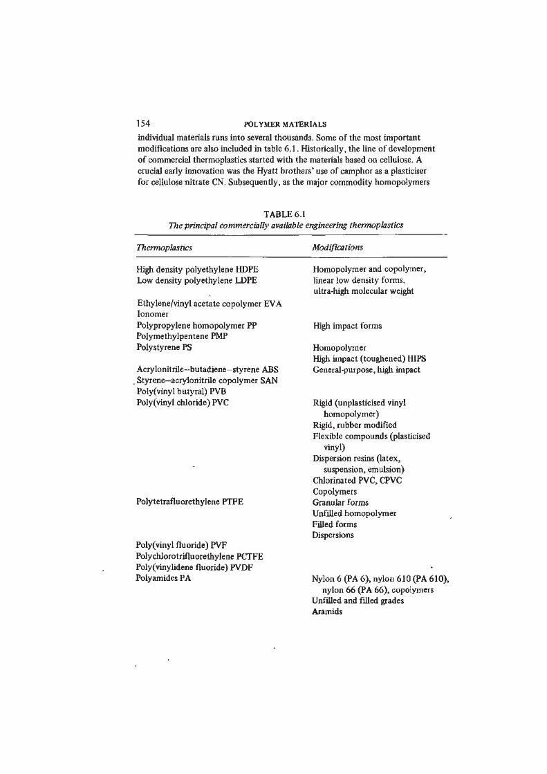
individual materials runs into several thousands. Some of the most important
modifications are also included in table 6.1. Historically, the line of development
of commercial thermoplastics started with the materials based on cellulose. A
crucial early innovation was the Hyatt brothers' use of camphor as a plasticiser
for cellulose nitrate CN. Subsequently, as the major commodity homopolymers
TABLE 6.1
The principal commercially available engineering thermoplastics
Thermoplastics Modifications
High density polyethylene HDPE
Low density polyethylene LDPE
Ethylene/vinyl acetate copolymer EVA
Ionomer
Polypropylene homopolymer PP
Polymethylpentene PMP
Polystyrene PS
Acrylonitrile—butadiene—styrene ABS
. Styrene—acrylonitrile copolymer SAN
Poly(vinyl butyral) PVB
Poly(vinyl chloride) PVC
Polytetrafluorethylene PTFE
Polyvinyl fluoride) PVF
Polychlorotrifluorethylene PCTFE
Poly(vinylidene fluoride) PVDF
Polyamides PA
Homopolymer and copolymer,
linear low density forms,
ultra-high molecular weight
High impact forms
Homopolymer
High impact (toughened) HIPS
General-purpose, high impact
Rigid (unplasticised vinyl
homopolymer)
Rigid, rubber modified
Flexible compounds (plasticised
vinyl)
Dispersion resins (latex,
suspension, emulsion)
Chlorinated PVC, CPVC
Copolymers
Granular forms
Unfilled homopolymer
Filled forms
Dispersions
Nylon 6 (PA 6), nylon 610 (PA 610),
nylon 66 (PA 66), copolymers
Unfilled and filled grades
Aramids
POLYMER MATERIALS AND THEIR TECHNOLOGY 155
TABLE 6.1 continued
Thermoplastics Modifications
Poly(methyl methacrylate) PMMA
Polyoxymethylene POM Acetal homopolymer
Acetal copolymer
Polysulphone PSU, Polyethersulphone
Polyetheretherketone PEEK
Polyester-urethane
Polyether-urethane
Poly(phenylene oxide) PPO PPO/PS and other blends
Poly(phenylene sulphide) PPS
Polycarbonate PC
Polyimide PI, Polyetherimide PEI
Poly(ethylene terephthalate) PETP
Poly(butylene terephthalate) PBTP
Polyarylate
Cellulose acetate CA
Cellulose acetate butyrate CAB
Ethyl cellulose
(Thermoplastic elastomers: see section 6.5)
PVC, PS and PE were introduced, the manufacturers overcame deficiencies in
their engineering properties by the use of additives. Plasticisers were developed
which greatly altered the mechanical behaviour of PVC; mineral fillers were found
to improve weathering and increase rigidity, and stabilisers to prevent thermal
decomposition during melt processing. PE was stabilised against photodegradation
for outdoor use. Property-modifying additives are now almost invariably
incorporated in commercial thermoplastics. We discuss the function of additives
and the compounding of polymers and additives more fully in the following
section.
From the early cellulose-derived materials right through to the present the
development of new polymers with novel primary chain structures has continued.
However, commercial materials of new structure are infrequent arrivals on the
polymer scene (as table 1.2 showed). In parallel, established materials are
repeatedly improved and modified by innovations in synthesis and in
compounding. One particularly fruitful and important theme in polymer
modification has been the development of the hybrid polymer. The first
important example of a hybrid material was high impact polystyrene HIPS. The
early exploitation of straight PS was bedevilled by its brittleness and attempts
were made in the 1940s to improve its performance by blending PS with rubbers.
Some success was achieved with simple two-phase physical mixtures, but in 1952
156 POLYMER MATERIALS
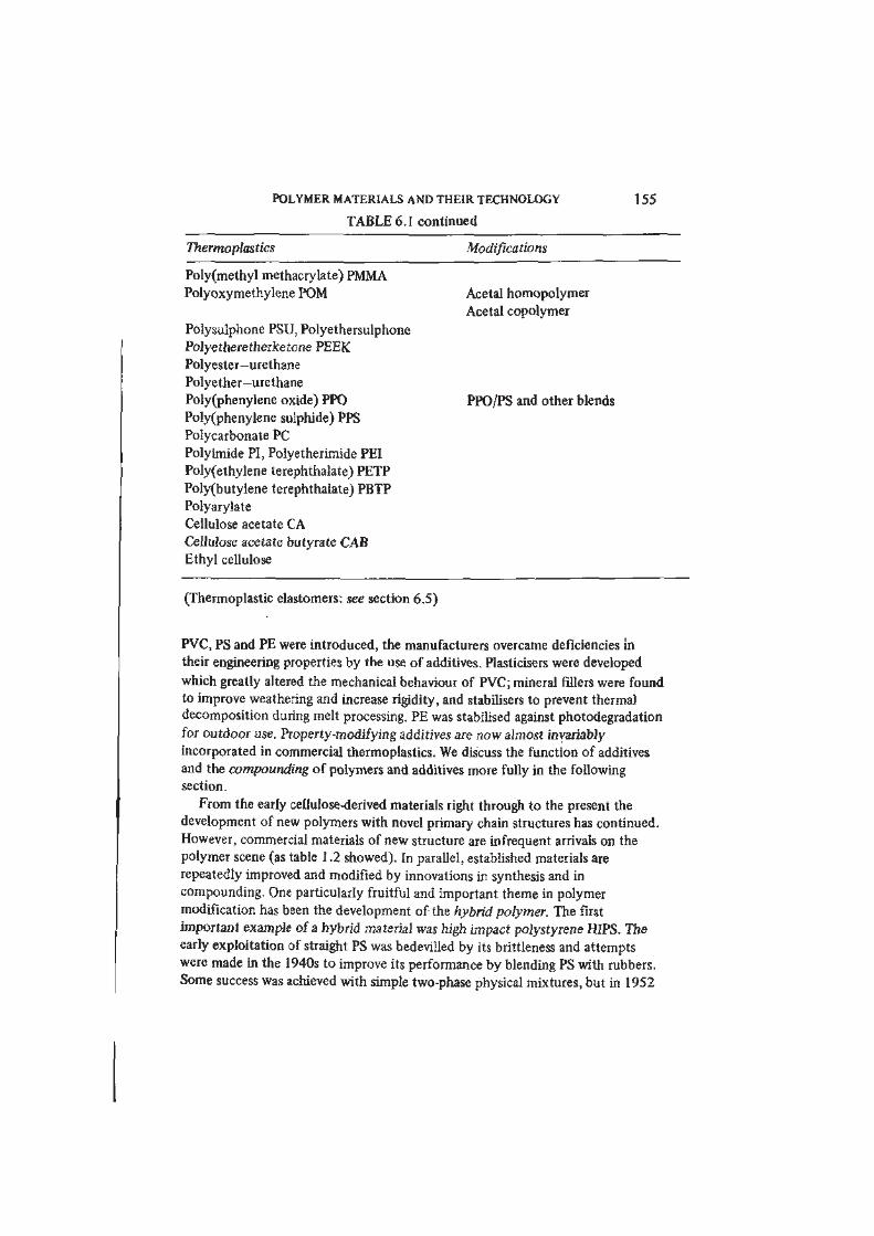
Figure 6.1 Morphology of high impact polystyrene HIPS, (a) Transmission
electron micrograph, showing dispersed elastomer particles (~ 2 /jm diameter)
with PS occlusions, (b) Scanning electron micrograph of elastomer particles
after dissolving PS matrix. (Courtesy of Dow Chemical Company)
the Dow Chemical Co. introduced a two-phase HIPS in which a graft copolymer
is formed at the interface between the PS matrix and dispersed SBR or BR
elastomer particles (figures 6.1 and 6.2). A little later the first of another major
type of rubber-toughened materials, the ABS thermoplastics, was introduced
commercially. These polymers also have a two-phase morphology and consist of
elastomer particles dispersed in a styrene—acrylonitrile SAN copolymer matrix.
These trends towards hybrid polymer materials led in the 1960s and 1970s also
to the emergence of polymer alloys, a name applied to rubber-toughened
materials in which the matrix is a mixture of polymer types. Among established
polymer alloys are ABS/PVC, ABS/PC, ABS/polysulphone, PMMA/PVC and
PPO/PS (modified PPO). Thus rubber toughening, copolymerisation, blending
and alloying have emerged as methods of polymer modification of great
importance and a current area of rapid growth. The characteristics of the various
types of hybrid polymer are summarised in table 6.2.
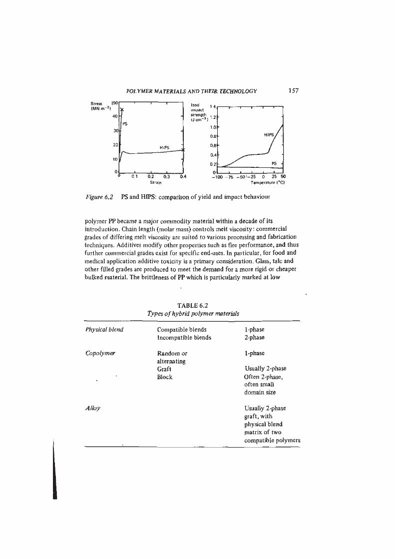
We can illustrate the role of chain structure, chain length, additives and
hybridising in polymer modification with the example of polypropylene PP and
its derivative thermoplastics. Figure 6.3 shows the relations between the
commercially important members of the PP family. Atactic PP produced by the
high pressure polymerisation of propene proved to have no commercial value as
a thermoplastic although it has limited use as an adhesive. On the other hand,
Ziegler—Natta catalysts promote stereospecific synthesis and isotactic homo-
POLYMER MATERIALS AND THEIR TECHNOLOGY 1 57
Stress
( M N n r
|b0
40
30
PS
T 1Izod , 4
impact
strength , ,
( J e m " * )1 2
1.0
0.8
20
10 rHIPS
•
0.620
10 r •
0.4
0 2
0 , ' , n0 1 0.2 0.3 0.4 _1
Strain
1 1 r- i i
>
H I P s / -
/ "
-'
• ^ s ^ PS -
• • — 1 1 1 —
-100 -75 - 5 0 ' - 2 5 0 25 50
Temperature (°C)
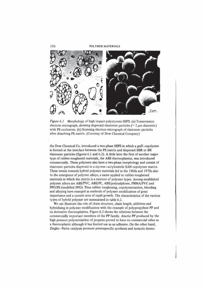
Figure 6.2 PS and HIPS: comparison of yield and impact behaviour
polymer PP became a major commodity material within a decade of its
introduction. Chain length (molar mass) controls melt viscosity: commercial
grades of differing melt viscosity are suited to various processing and fabrication
techniques. Additives modify other properties such as fire performance, and thus
further commercial grades exist for specific end-uses. In particular, for food and
medical application additive toxicity is a primary consideration. Glass, talc and
other filled grades are produced to meet the demand for a more rigid or cheaper
bulked material. The brittleness of PP which is particularly marked at low
TABLE 6.2
Types of hybrid polymer materials
Physical blend Compatible blends
Incompatible blends
1-phase
2-phase
Copolymer Random or
alternating
Graft
Block
1-phase
Usually 2-phase
Often 2-phase,
often small
domain size
Alloy Usually 2-phase
graft, with
physical blend
matrix of two
compatible polymers
158 POLYMER MATERIALS
Homopolymer
Bltnd
hybrid
Copolymer
Figure 6.3
elastomers
Members of the polypropylene family of thermoplastics and
temperatures and is a serious disadvantage for certain applications may be
greatly reduced by copolymerisation. Random copolymers of propylene and
ethylene (EPM) or terpolymers of propylene, ethylene and a diene (EPDM) are
elastomers, and of major importance in their own right (see section 6.5).
Toughened or high impact grades of PP may be produced by the mechanical
blending of PP with EPM or EPDM. More recently new toughened PP materials
(known as polyallomers) have been introduced which are formed by the direct
copolymerisation of propylene and ethylene (2-10 per cent) in such a way that
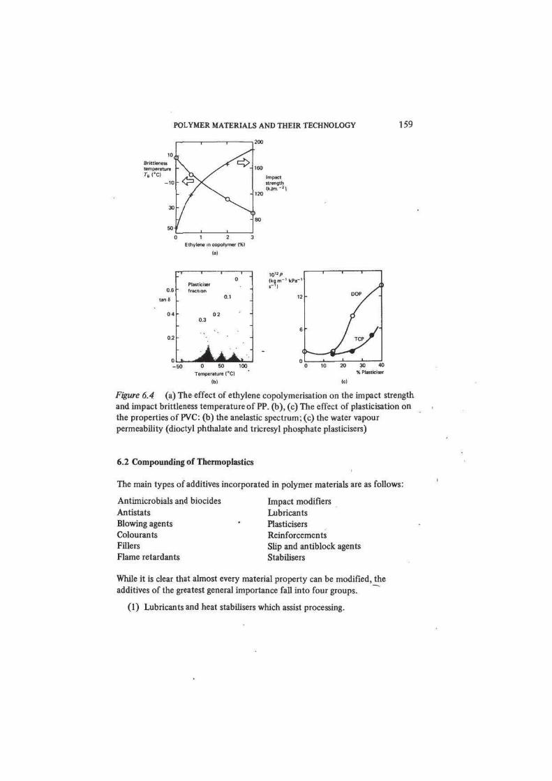
block copolymer structures are formed. Figure 6.4(a) shows the marked
improvement in impact performance which results from incorporating small
amounts of ethylene to form a block copolymer.
POLYMER MATERIALS AND THEIR TECHNOLOGY 159
0 1 2 3
Ethylene in copolymer (%)
lal
06
tanfi
1 1 1
0Plasticiserfraction
0.1
0 4 • 020.3
• "0 2 • "
. i •
050 0 50 100
10'2/>
(ko,m-' kPa-'
Temperature 1°C)
M
1 1 1
DOP / .
/ /•
_ l 1
30 40% Pl«t*ciser
10
Figure 6.4 (a) The effect of ethylene copolymerisation on the impact strength
and impact brittleness temperature of PP. (b), (c) The effect of plasticisation on
the properties of PVC: (b) the anelastic spectrum; (c) the water vapour
permeability (dioctyl phthalate and tricresyl phosphate plasticisers)
6.2 Compounding of Thermoplastics
The main types of additives incorporated in polymer materials are as follows:
Antimicrobials and biocides
Antistats
Blowing agents
Colourants
Fillers
Flame retardants
Impact modifiers
Lubricants
Plasticisers
Reinforcements
Slip and antiblock agents
Stabilisers
While it is clear that almost every material property can be modified, the
additives of the greatest general importance fall into four groups.
(1) Lubricants and heat stabilisers which assist processing.
160 POLYMER MATERIALS
(2)' Fillers, impact modifiers, plasticisers, reinforcements and coupling
agents which modify mechanical properties of the material in-use.
(3) Flame retardants which modify the fire properties of the material.
(4) Stabilisers (antioxidants and antiozonants) which increase the
degradation resistance of the material in use.
In chapter 5 we described the value of the solubility parameter of solvents
• and polymers as a guide to polymer solubility and compatibility. We noted
that when thermoplastics absorb small amounts of compatible solvents they
become softer and less rigid. Commercially, the use of plasticisers is confined to
a small number of polymer materials. PVC is the chief of these, accounting for
about 90 per cent of all plasticiser use; the remainder is used in compounding
PVAC, certain elastomers and cellulose-based materials. The majority of
plasticisers for PVC (5 9.6) arc non-volatile esters such as dibutyl phthalate
(6 9.3) or trixylyl phosphate (8 9.7); common solvents are too easily lost by
evaporation. The effect of plasticiser is to reduce the modulus, shift mechanical
loss peaks to lower temperatures (that is, transition temperatures are depressed),
to decrease hardness, and to increase creep and permeability (figure 6.4). As we
have remarked elsewhere, plasticisation may also entail deterioration of
electrical performance and durability.
Fillers, by contrast, serve generally to increase modulus and hardness, and to
reduce creep, thermal expansivity and cost. Fillers are powdered or short-fibre
materials, such as wood flour, glass fibre, silica, talc, kaolin and calcium carbonate.
Whereas plasticisers are dissolved in the polymer and act at the molecular level
(reducing interchain forces for example), the filler particles form a distinct phase
in a mechanical mixture. They exert their influence on the properties of the
compounded solid through composite action with the polymer matrix.
The flame retardant and stabiliser additives are substances chosen to interfere
with the chemical reactions underlying combustion, oxidation and other modes
of chemical degradation. The variety of compounds used for these purposes is
enormous. We can do no more than indicate by way of illustration (figure 6.5)
the mode of action of two typical additives.
Synergistic Bromine-Antimony Flame Retardants for PP
OH' and other radicals which participate in the combustion flame reactions (see
reactions 5.6 and 5.7, p. 136) may be removed by inhibitors such as hydrogen
bromide, HBr. HBr is formed in situ from the decomposition of a bromine-
containing organic compound (such as hexabromocyclodecane HBCD)
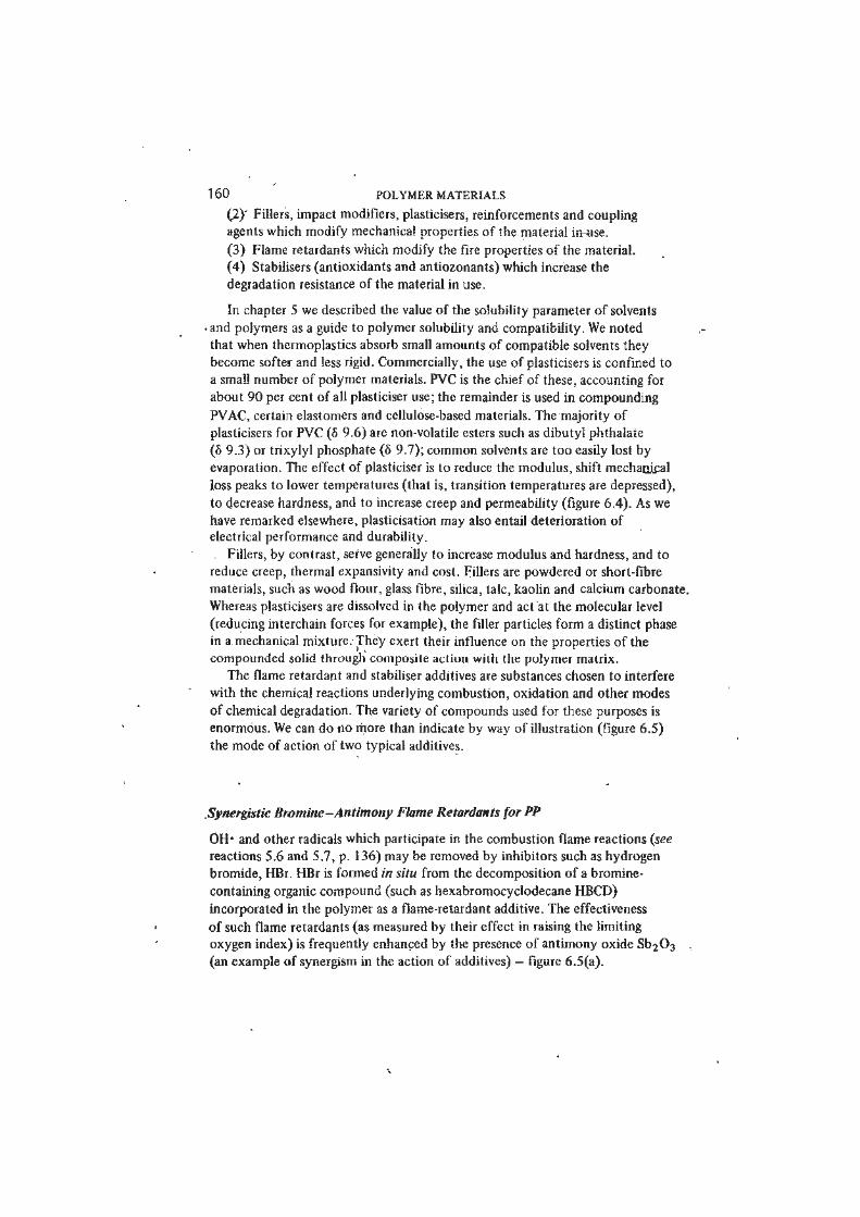
incorporated in the polymer as a flame-retardant additive. The effectiveness
of such flame retardants (as measured by iheir effect in raising the limiting
oxygen index) is frequently enhanced by the presence of antimony oxide Sb 20 3
(an example of synergism in the action of additives) — figure 6.5(a).
POLYMER MATERIALS AND THEIR TECHNOLOGY 161
LOI
3 4 HBCD(%)
Figure 6.5(a) Mode of action of flame retardant additive HBCD of the flamepoison type
Under flame conditions the following reactions occur
HBCD + Sb 20 3 > SbBr3 antimony bromide
SbBr3 » Br- radical
Br* + polymer pyrolysis products > HBr
OH» + HBr • H 20 + Br-
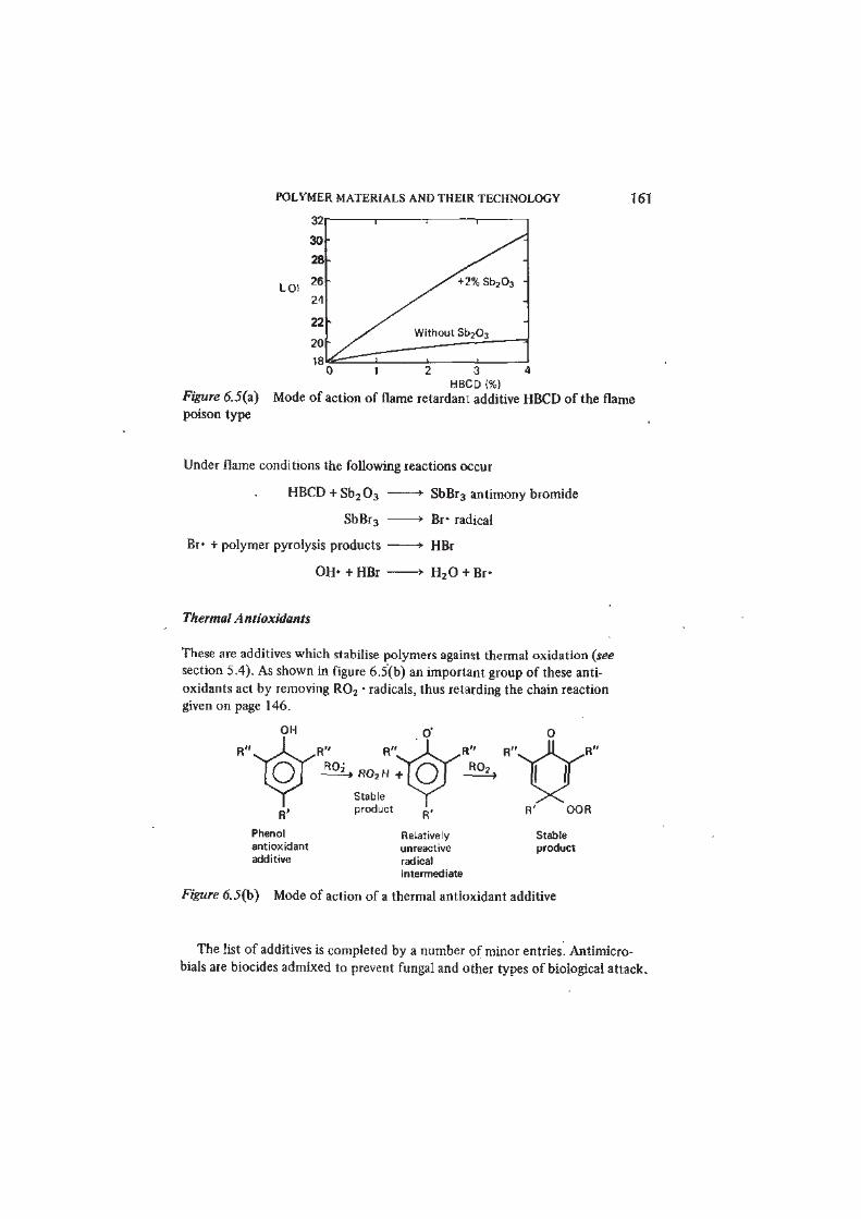
Thermal Antioxidants
These are additives which stabilise polymers against thermal oxidation (see
section 5.4). As shown in figure 6.5(b) an important group of these anti-
oxidants act by removing R02 • radicals, thus retarding the chain reaction
given on page 146.
R02H + [ 0
Stable
product
Phenol
antioxidant
additive
Relatively
unreactive
radical
intermediate
Stable
product
Figure 6.5(b) Mode of action of a thermal antioxidant additive
The list of additives is completed by a number of minor entries. Antimicro-
bials are biocides admixed to prevent fungal and other types of biological attack.
162 POLYMER MATERIALS
These substances are necessarily somewhat toxic and their inclusion may not be
permitted for certain end-uses. However, they are frequently incorporated into
surface coating formulations.
Antistats (commonly glycerol esters) act to reduce triboelectric charging by
lowering resistivity. Blowing agents are used in forming cellular (foamed) plastics
and are discussed in section 6.6 below. Reinforcements are considered in sections
6.9 and 6.10 under the headings of fibres and composites. Colourants embrace
pigments (insoluble, finely divided solids) and soluble dyes, selected for colour
stability, inertness and lack of toxicity. Pigments may act to some extent as
fillers; their optical properties are discussed in section 6.8.
/
6.3 Processing and Fabrication of Thermoplastics
Processing and fabrication describe the conversion of materials from stock form
(bar, rod, tube, pellet, sheet and so on) to a more or less complicated artefact.
Whatever the material the shaping process must involve one or more variants of
cutting, joining and moulding. Wood is almost invariably worked by cutting and
joining operations. Techniques for shaping metals are very diverse; methods of
cutting and joining are highly developed, but casting, sintering, pressing and
rolling processes are also widely used. Moulding techniques predominate in the
technologies of glass and ceramics. Polymer materials have proved especially
amenable to a variety of extrusion and moulding techniques. In particular the
following principal processing and fabricating operations for thermoplastics
now enable products and components of complex shape to be mass-produced on
a very large scale
Extrusion-'
Injection nCoulding
Blow moujdfng
Rotational moulding
Calendering
Thermofqrmjrrg (sheet moulding)
Casting
Sintering
Machining
Cold-forming
Welding
Cementing
The most important processing and fabricating techniques for thermoplastics
exploit their generally low melting temperatures and shape the materials from
the melt. Extrusion and injection moulding are the most widely used processes,
and they are illustrated in figure 6.6(a, b). The screw extruder accepts raw
POLYMER MATERIALS AND THEIR TECHNOLOGY 163
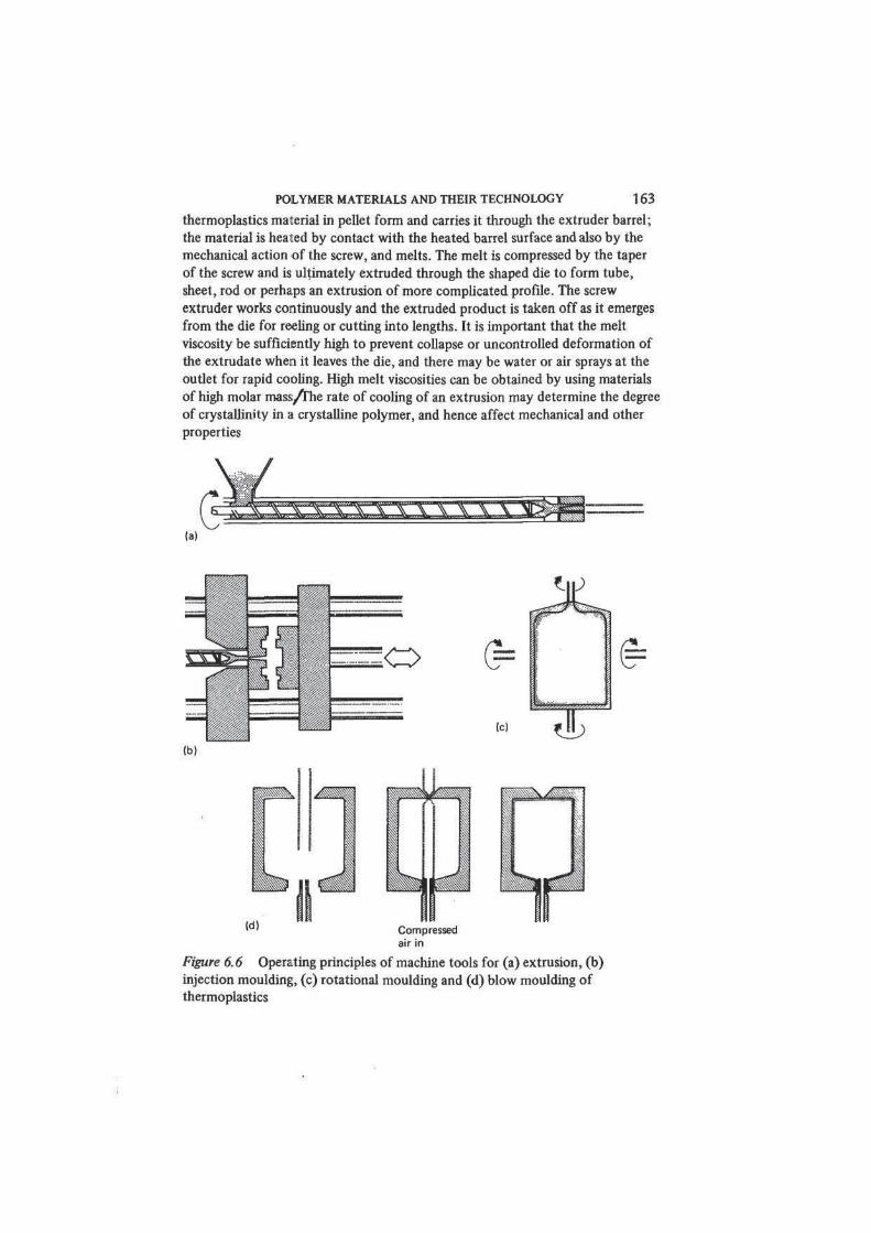
thermoplastics material in pellet form and carries it through the extruder barrel;
the material is heated by contact with the heated barrel surface and also by the
mechanical action of the screw, and melts. The melt is compressed by the taper
of the screw and is ultimately extruded through the shaped die to form tube,
sheet, rod or perhaps an extrusion of more complicated profile. The screw
extruder works continuously and the extruded product is taken off as it emerges
from the die for reeling or cutting into lengths. It is important that the melt
viscosity be sufficiently high to prevent collapse or uncontrolled deformation of
the extrudate when it leaves the die, and there may be water or air sprays at the
outlet for rapid cooling. High melt viscosities can be obtained by using materials
of high molar mass/the rate of cooling of an extrusion may determine the degree
of crystallinity in a crystalline polymer, and hence affect mechanical and other
properties
1 0' Compressed
air in
Figure 6.6 Operating principles of machine tools for (a) extrusion, (b)
injection moulding, (c) rotational moulding and (d) blow moulding of
thermoplastics
164 POLYMER MATERIALS
Injection moulding describes a process in which polymer melt is forced into a
mould, where it cools until solid. The mould then separates into two halves to
allow the product to be ejected; subsequently the parts of the mould are clamped
together once more, a further quantity of melted material is injected and the
cycle repeated. The injection end of the machine is most commonly an
archimedean screw (similar to that of a screw extruder) which can produce,
once per cycle, a shot of molten polymer of predetermined size and then inject
it into the mould by means of a reciprocating ram action. Low melt viscosity is
desirable to obtain good flow within the mould cavities, but high injection
temperatures mean longer cooling periods, longer cycle times and lower
production rates Alould and product design are influenced by consideration of
polymer flow patterns, orientation and crystaUisation effects7Injection moulding
provides a particularly effective way of obtaining complex shapes in large
production runs. Although simple in principle large injection moulding machines
are technically complex, and the design and fabrication of moulds can be costly.
As the size and/or aspect ratio of an injection moulding increase it becomes
more difficult to ensure uniformity in the polymer during injection and to
maintain a sufficient clamping force to keep the mould closed during filling. With
injection back pressures of several hundred bars, clamping forces can easily reach
tens of tons. The reaction injection moulding process has been developed to over-
come both these problems, essentially by carrying out most of the polymerising
reaction in the mould so that injection viscosities (and therefore back pressures)
are reduced by more than two orders of magnitude. The urethanes, which
constitute the main class of reaction injection systems, are used extensively to
fill cavities with rigid and flexible foams. Recently reaction-injected glass fibre
reinforced elastomeric urethanes have come into prominence, since they seem
likely to have the requisite combination of adequate mechanical properties and
low mould-cycle times (< 1 min) needed for car body panels.
Blow moulding, figure 6.6(d), represents a development of extrusion in which
hollow articles are fabricated by trapping a length of extruded tube (the parison)
and inflating it within a mould. The simple extruded parison may be replaced by
an injection-moulded preform. Hollow articles including those of large
dimensions may also be produced by rotational moulding (or rotocasting). A
charge of solid polymer, usually powder, is introduced into a mould which is
first heated to form a melt. The mould is then rotated about two axes to coat
its interior surface to a uniform thickness — figure 6.6(c).
Polymeric materials in continuous sheet form are often produced and
subsequently reduced in thickness by passing between a series of heated rollers,
an operation known as calendering. Thermoforming employs suction or air
pressure to shape a thermoplastic sheet heated above its softening temperature
to the contours of a male or female mould. Certain thermoplastics can be shaped
without heating in a number of cold-forming operations such as stamping and
forging commonly applied to metals.
POLYMER MATERIALS AND THEIR TECHNOLOGY 165
All these methods of fabrication/are essentially moulding processes. Cutting
techniques (embracing all the conventional machining operations: turning,
drilling, grinding, milling and planing) can also be applied to thermoplastics, but
they are used much less widely. In comparison with metalworking, difficulties
arise from the low melting temperatures, low thermal conductivities and low
moduli of polymer materials which in consequence are relatively easily deformed
by the cutting tool. Cutting actions are less precise than on metals and heating
at the tool surface must be avoided. Nevertheless with appropriate depth of cut,
rate of feed and tool geometry conventional machine tools may often be used.
(The relatively poorer performance of mechanical fastenings also militates against
cutting and joining as a general method of fabrication for thermoplastics.) These
techniques are most commonly applied to glassy polymers such as PMMA and to
thermoplastic composites such as glass-filled PTFE, although softer materials
such as PE and unfilled PTFE have excellent machinability.
Many thermoplastics may be satisfactorily cemented either to similar or
dissimilar materials (adhesives are discussed in section 6.7). A number of inert
and insoluble polymer materials such as PTFE, PCTFE and some other
fluoropolymers, PE, PP and some other polyolefins are amenable to cementing
only after vigorous surface treatment. For the lower melting thermoplastics
welding provides an important alternative for joining parts of the same material,
for example in fabricating pipework. The thermoplastics of higher melting
temperature (which include PTFE of the common engineering polymers and also
some of the specialised heat-tolerant materials such as the polyimides) cannot be
satisfactorily fabricated by the principal extrusion and injection moulding
processes. These materials are shaped by sintering powdered polymer in
pressurised moulds, a process which causes the polymer particles to coalesce.
Sintered products are normally somewhat more porous than those made from
thermoplastics which are processed by way of the melt.
6.4 Thermosets
Thermoset materials are produced by the direct formation of network polymers
from monomers, or by crosslinking linear prepolymers. Once formed the
polymer cannot be returned to a plastic state by heating. For thermosets
therefore the polymerisation (or at least its final curing stage) and the shaping
process occur simultaneously. Long-established and relatively simple processing
methods for thermosets include casting and compression and transfer moulding.
More recently, automatic injection moulding of thermosets has been successfully
developed and is now widely used.
The principal thermosets are the phenolics, the amino resins (UF and MF),
the epoxies, the unsaturated polyesters (including the surface coating alkyds
described in section 6.8) and the crosslinked polyurethanes. Of less importance
are the crosslinked silicones, the furan resins and the allyl resins, notably allyl
166 POLYMER MATERIALS
diglycol carbonate. The chemistry of the thermoset resins is generally more
complicated than that of the thermoplastics. All are formed by the reaction of at
least two types of monomer, usually in a sequence of polymerisation and
crosslinking stages. Unlike the thermoplastics processor, the fabricator working
with thermoset materials has to carry out the final curing reactions.
We have already described in outline in section 1.14 how thermosets of the
unsaturated polyester and epoxy type are formed. In both these cases the first
stage of polymerisation is the construction in a condensation reaction of a short
linear chain (the relative molecular mass generally lies between 500 and 5000,
corresponding to 2-12 monomer units). The uncured resins are stable and are
made available to the user as liquids of various viscosities, as pastes or, in the
case of the longer chain epoxies, as solids with melting temperatures up to 150 °C
The final curing of the resins is achieved by combining the UP or EP resin
immediately before moulding with hardeners or curing agents which crosslink
the polymer chains through reactive groups. The C=C double bonds of the UP
chains are coupled tlirough slyrene crosslinks by the action of free radical
initiators. The epoxies crosslink through the terminal >C—C< groups by reaction
O
with amines or anhydrides. Different curing agents require different curing
conditions and curing times. The various base resins in combination with selected
curing agents produce thermosets having somewhat different properties.
Therefore an epoxy or polyester system comprising a base resin and curing agent
may be tailored to a particular application, for which certain electrical,
mechanical or thermal properties and also cost are optimised as appropriate.
For example, fire performance of polyesters is improved by replacing phthalic
acid by tetrachlorophthalic acid. Impact strength is increased by incorporating
carbon chain acids such as adipic acid HOOC(CH2)8COOH in the UP polymer.
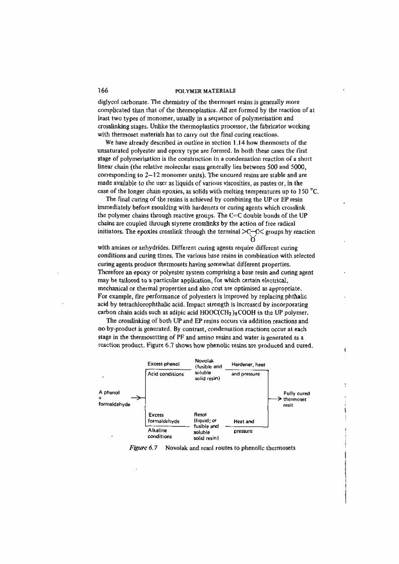
The crosslinking of both UP and EP resins occurs via addition reactions and
no by-product is generated. By contrast, condensation reactions occur at each
stage in the thermosetting of PF and amino resins and water is generated as a
reaction product. Figure 6.7 shows how phenolic resins are produced and cured.
A phenol
+formaldehyde
Excess phenol
Acid conditions
Excess
formaldehyde
Alkaline
conditions
Novolak
(fusible and
soluble
solid resin)
Resol
(l iquid; or
fusible and
soluble
solid resin)
Hardener, heat
and pressure
Heat and
pressure
Fully cured
- ^ thermoset
resit
Figure 6.7 Novolak and resol routes to phenolic thermosets
POLYMER MATERIALS AND THEIR TECHNOLOGY 167
The novolak formed in the two-stage process is a useful partially polymerised
but still fusible intermediate. This can be combined with a filler such as wood
flour and a crosslinking agent or hardener (normally hexamethylene tetramine)
to form a moulding powder, which is finally fully cured only under the action
of heat and pressure in the mould. Phenolic laminates are usually made from
resols, in what is described as a one-stage process, since the addition of a
hardener is not necessary. The condensation polymerisation proceeds essentially
continuously from raw materials to the fully cured resit, although intermediate
stages in the development of the network polymer are recognised and the
polymerisation may be interrupted at the resol stage.
6.5 Elastomers
The defining characteristic of elastomers as a class is their high elasticity — the
capacity for very large rapidly recoverable deformation. As we have seen in
chapter 3 such behaviour appears in lightly crosslinked amorphous polymers
above their glass transition temperatures. Elastomeric mechanical behaviour
was first fully realised in natural rubber NR vulcanised by reaction with sulphur
(Goodyear and Hancock, about 1840). Rubber rapidly proved an immensely
useful material and soon became indispensable to the industrial nations.
Germany and the United States in particular sought urgently to develop
synthetic substitutes to secure their resources of this vital material and from the
1920s onwards a succession of synthetic rubbers were developed. Finally in
1954 a stereoregularc/s-l,4-polyisoprene essentially identical to natural rubber
was synthesised, using Ziegler—Natta and other catalysts. This synthetic
polyisoprene rubber IR was subsequently put into successful commercial
production.
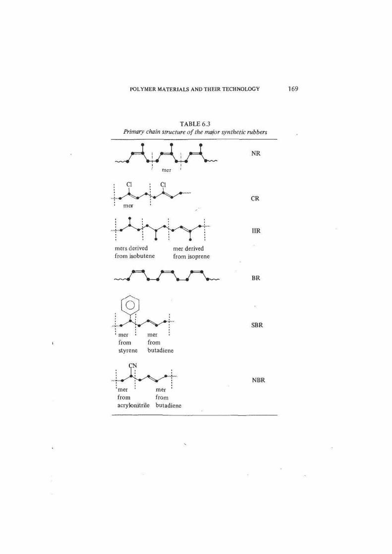
All these synthetic materials were closely modelled on natural rubber, being
linear chain polydienes and random copolymers, with C=C double-bond
unsaturation in the chain to permit irreversible crosslinking, essentially as in
natural rubber itself (table 6.3). The residual unsaturation of the unvulcanised
chain is achieved by using a diene monomer with two C=C double bonds. Only
half this unsaturation disappears during polymerisation, leaving one C=C bond
per diene monomer unit. For example, polybutadiene
More recently (notably with the introduction of polyurethane elastomers (AU
and EU) in the early 1950s) other materials have appeared, which while
possessing high elasticity differ considerably from the rubbers in other properties
and in structure. Some of these elastomers are close structural relations of
thermoplastics and thermosets. Some, such as the Y class thermoplastic
r+,
168 POLYMER MATERIALS
elastomers, based on block copolymers, represent major advances in polymer
materials. Taken together these trends indicate a marked diversification in
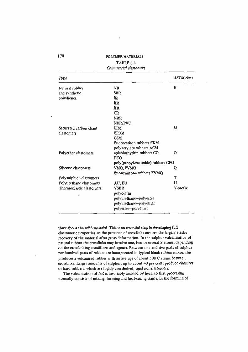
elastomer technology. Table 6.4 lists elastomer materials of current commercial
importance {see also figure 1.1 for world consumption data).
Despite the competition of highly developed synthetic materials, natural
rubber has retained a leading place among commodity and engineering elastomers,
and production increases year by year. The growth of the rubber industry from
the seeds of the wild rubber tree of Brazil is a remarkable achievement of
agriculture and applied chemistry. Rubber cultivation consists in the production
of a stereoregular hydrocarbon polymer as a crop, by biosynthesis, using solar
energy, carbon dioxide, water and the elaborate metabolic reactions of plant
tissue: a model perhaps of future materials biotechnologies. The interesting
techniques which were evolved in the nineteenth and early twentieth centuries
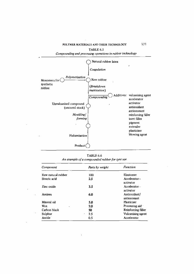
to convert raw rubber latex to useful commercial rubbers are outlined in table 6.5.
These operations provide the basis also for the technology of synthetic rubbers.
Natural rubber latex is a dispersion of rubber particles (0.1-1.6 /iin
diameter) in water. Unvulcanised raw rubber obtained by coagulating and
drying the rubber latex has a very high molar mass (with average chain lengths
of the order of 100 000 C atoms) and before compounding the rubber is
masticated. Mastication, which involves mechanically working the rubber for
some minutes, reduces the chain length by a factor of about 10, and converts the
raw gum to a plastic mass. In this state, the rubber can be compounded with
additives, including most importantly vulcanising agents, stabilisers and reinforcing
fillers. Sulphur, the original vulcanising agent for natural rubber, remains pre-
eminent, but its effectiveness has been enhanced and brought under control by
the use of accelerators and activators.
The stabilisers are substances which inhibit the oxidative ageing and ozone
attack to which natural rubber is subject. They act by intercepting active free
radicals and breaking the sequence of degradation reactions (see sections 5.4 and
6.2). Amines and phenols are used. The reinforcing fillers, of which finely
divided carbon powders (carbon blacks) are by far the most important, serve to
improve mechanical end-use properties such as modulus and hardness, abrasion
and tear resistance (figure 6.8). The mechanism of reinforcement remains some-
what obscure; it is clear from measurements of the viscosity and solubility of
unvulcanised mixes that the rubber adheres strongly to the carbon surface, and
generally the reinforcing effects of carbon blacks increase with decreasing
particle size. Furnace blacks with particle diameters around 0.02—0.06 nm are
most commonly used. Carbon blacks are also highly efficient in absorbing
ultraviolet light and some also significantly increase electrical conductivity,
reducing triboelectric charging and acting as antistats. Inert fillers such as
pigments and extenders are frequently included in the compounded rubber mix,
to which may also be added process and extender oils — see table 6.6.
The vulcanising agent reacts with the unsaturated polyisoprene chains of NR
forming crosslinks and tying the molecules together chemically at certain points
POLYMER MATERIALS AND THEIR TECHNOLOGY 169
TABLE 6.3
Primary chain structure of the major synthetic rubbers
NR
mer
CR
mers derived
from isobutenemer derived
from isoprene
IIR
BR
SBR
mer • mer
from from
styrene butadiene
NBR
mer mer
from from
acrylonitrile butadiene
170 POLYMER MATERIALS
TABLE 6.4
Commercial elastomers
Type ASTM class
Natural rubber NR R
and synthetic SBR
polydienes IR
BR
IIR
CR
NBR
NBR/PVC
Saturated carbon chain EPM M
elastomers EPDM
CSM
fluorocarbon rubbers FKM
polyacrylate rubbers ACM
Polyether elastomers epichlorhydrin rubbers CO
ECO
0
poly(propylene oxide) rubbers GPO
Silicone elastomers VMQ, PVMQ
fluorosilicone rubbers FVMQQ
Polysulphide elastomers T
Polyurethane elastomers AU,EU U
Thermoplastic elastomers YSBR
polyolefin
polyurethane-polyester
polyurethane-polyether
polyester—polyether
Y-prefix
throughout the solid material. This is an essential step in developing full
elastomeric properties, as the presence of crosslinks ensures the largely elastic
recovery of the material after gross deformation. In the sulphur vulcanisation of
natural rubber the crosslinks may involve one, two or several S atoms, depending
on the crosslinking conditions and agents. Between one and five parts of sulphur
per hundred parts of rubber are incorporated in typical black rubber mixes: this
produces a vulcanised rubber with an average of about 500 C atoms between
crosslinks. Larger amounts of sulphur, up to about 40 per cent, produce ebonites
or hard rubbers, which are highly crosslinked, rigid nonelastomers.
The vulcanisation of NR is invariably assisted by heat, so that processing
normally consists of mixing, forming and heat-curing stages. In the forming of
POLYMER MATERIALS AND THEIR TECHNOLOGY 171
TABLE 6.5
Compounding and processing operations in rubber technology
Q Natural rubber latex
Coagulation
^^ Polymerisation —.Monomers for ( J • • (J Raw rubber
synthetic
rubber (fireaWow*
mastication)
\_) Additives: vulcanising agent
accelerator
activator
antioxidant
antiozonant
reinforcing filler
inert filler
pigment
extender
plasticiser
blowing agent
Unvulcanised compound
(uncured stock)
Compounding
0Moulding/
forming
0Vulcanisation
Product ( j
TABLE 6.6
An example of a compounded rubber for tyre use
Component Parts by weight Function
Raw natural rubber 100
Stearic acid 2.5
Zinc oxide 3.5
Amines 6.0
Mineral oil 5.0
Wax 2.0
Carbon black 50
Sulphur • 2.5
Amide 0.5
Elastomer
Accelerator-
activator
Accelerator-
activator
Antioxidant/
antiozonant
Plasticiser
Processing aid
Reinforcing filler
Vulcanising agent
Accelerator
172 POLYMER MATERIALS
2.0log ob
(MN m-2)
1.6
1.2
0.8
0.4'
0
-0 .40 0 2 0.4 0.6 0.8
loge„
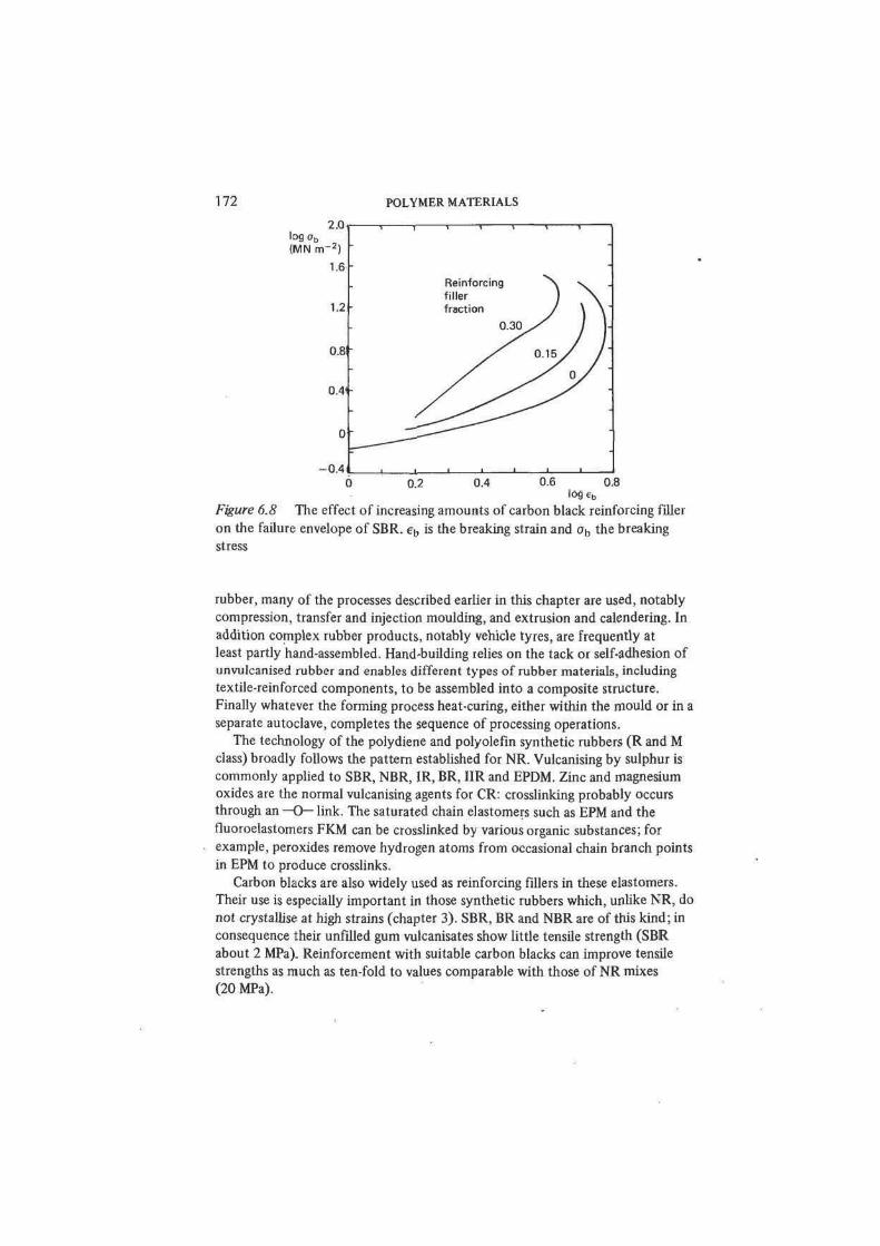
Figure 6.8 The effect of increasing amounts of carbon black reinforcing filler
on the failure envelope of SBR. e^ is the breaking strain and ob the breaking
stress
rubber, many of the processes described earlier in this chapter are used, notably
compression, transfer and injection moulding, and extrusion and calendering. In
addition complex rubber products, notably vehicle tyres, are frequently at
least partly hand-assembled. Hand-building relies on the tack or self-adhesion of
unvulcanised rubber and enables different types of rubber materials, including
textile-reinforced components, to be assembled into a composite structure.
Finally whatever the forming process heat-curing, either within the mould or in a
separate autoclave, completes the sequence of processing operations.
The technology of the polydiene and polyolefin synthetic rubbers (R and M
class) broadly follows the pattern established for NR. Vulcanising by sulphur is
commonly applied to SBR, NBR, 1R, BR, IIR and EPDM. Zinc and magnesium
oxides are the normal vulcanising agents for CR: crosslinking probably occurs
through an —O— link. The saturated chain elastomers such as EPM and the
fluoroelastomers FKM can be crosslinked by various organic substances; for
example, peroxides remove hydrogen atoms from occasional chain branch points
in EPM to produce crosslinks.
Carbon blacks are also widely used as reinforcing fillers in these elastomers.
Their use is especially important in those synthetic rubbers which, unlike NR, do
not crystallise at high strains (chapter 3). SBR, BR and NBR are of this kind; in
consequence their unfilled gum vulcanisates show little tensile strength (SBR
about 2 MPa). Reinforcement with suitable carbon blacks can improve tensile
strengths as much as ten-fold to values comparable with those of NR mixes
(20 MPa).
J 1 I • • L
POLYMER MATERIALS AND THEIR TECHNOLOGY 173
All the elastomers so far described are carbon-chain polymers of quite simple
primary structure, either homopolymer or copolymer, produced by free radical
chain reactions. In some contrast the polyurethane elastomers (class U) form a
major group of heterochain polymer materials of considerable structural diversity.
The structural basis of the AU and EU elastomers is outlined in a simple form in
table 6.7. The range of structure in these materials arises from the way in which
several different monomers are incorporated in successive step reactions. The
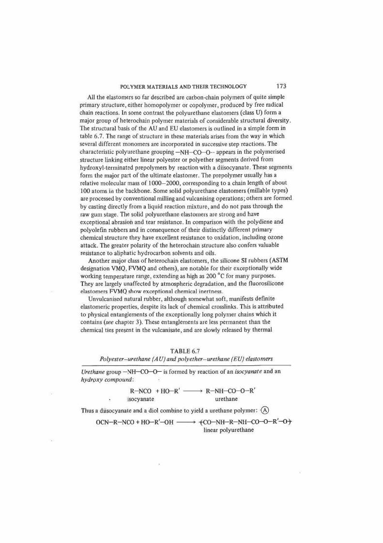
characteristic polyurethane grouping —NH—CO—0~ appears in the polymerised
structure linking either linear polyester or polyether segments derived from
hydroxyl-terminated prepolymers by reaction with a diisocyanate. These segments
form the major part of the ultimate elastomer. The prepolymer usually has a
relative molecular mass of 1000—2000, corresponding to a chain length of about
100 atoms in the backbone. Some solid polyurethane elastomers (millable types)
are processed by conventional milling and vulcanising operations; others are formed
by casting directly from a liquid reaction mixture, and do not pass through the
raw gum stage. The solid polyurethane elastomers are strong and have
exceptional abrasion and tear resistance. In comparison with the polydiene and
polyolefin rubbers and in consequence of their distinctly different primary
chemical structure they have excellent resistance to oxidation, including ozone
attack. The greater polarity of the heterochain structure also confers valuable
resistance to aliphatic hydrocarbon solvents and oils.
Another major class of heterochain elastomers, the silicone SI rubbers (ASTM
designation VMQ, FVMQ and others), are notable for their exceptionally wide
working temperature range, extending as high as 200 °C for many purposes.
They are largely unaffected by atmospheric degradation, and the fluorosilicone
elastomers FVMQ show exceptional chemical inertness.
Unvulcanised natural rubber, although somewhat soft, manifests definite
elastomeric properties, despite its lack of chemical crosslinks. This is attributed
to physical entanglements of the exceptionally long polymer chains which it
contains (see chapter 3). These entanglements are less permanent than the
chemical ties present in the vulcanisate, and are slowly released by thermal
TABLE 6.7
Polyester-urethane (A Uj and polyether-urethane (EU) elastomers
Urethane group —NH—CO—O— is formed by reaction of an isocyanate and an
hydroxy compound:
R-NCO + HO-R' • R-NH-CO-O-R'
isocyanate urethane
Thus a diisocyanate and a diol combine to yield a urethane polymer: (A)
OCN-R-NCO + HO-R'-OH • -(CO-NH-R-NH-CO-O-R'-O)-
linear polyurethane
174 POLYMER MATERIALS
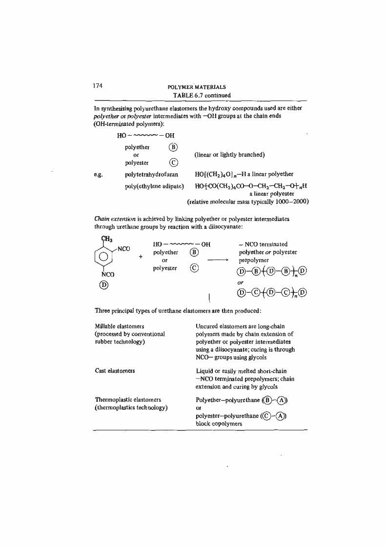
TABLE 6.7 continued
In synthesising polyurethane elastomers the hydroxy compounds used are either
polyether or polyester intermediates with —OH groups at the chain ends
(OH-terminated polymers):
HO OH
®©
e.g. polytetrahydrofuran
poly(ethylene adipate)
polyether
or
polyester
(linear or lightly branched)
HO[(CH2)40] „ -H a linear polyether
HOtCO(CH2)4CO-0-CH2-CH2H>i-„H
a linear polyester
(relative molecular mass typically 1000-2000)
Chain extension is achieved by linking polyether or polyester.intermediates
through urethane groups by reaction with a diisocyanate:
CH3
, / V ^ N C O
fNCO
®
HO
polyether
or
polyester
OH
®©
1
- NCO terminated
polyether or polyester
—• prepolymer
or
Three principal types of urethane elastomers are then produced:
Millable elastomers
(processed by conventional
rubber technology)
Cast elastomers
Thermoplastic elastomers
(thermoplastics technology)
Uncured elastomers are long-chain
polymers made by chain extension of
polyether or polyester intermediates
using a diisocyanate; curing is through
NCO— groups using glycols
Liquid or easily melted short-chain
—NCO terminated prepolymers; chain
extension and curing by glycols
Polyether-polyurethane ((5)-{X))
or
polyester-polyurethane ((C)-(A))
block copolymers
POLYMER MATERIALS AND THEIR TECHNOLOGY 175
motion, so that raw rubber exhibits marked creep and set in long-term tests.
However, in short timescale measurements (such as rebound) it shows elastomeric
behaviour.
If physical entanglements in an amorphous polymer above Tg lack permanence,
do there exist other physical means of tying molecular chains together to
produce elastomers? The successful development since the mid-1960s of a series
of commercial thermoplastic elastomers shows decisively that this is so. The
materials of this class are now available are based on styrene-butadiene, polyether,
polyester and polyurethane block copolymers. Ethylene-propylene thermo-
plastic elastomers are probably of the same type. The styrene—butadiene materials
have been most fully studied and characterised. They consist of A—B—A
styrene-butadiene-styrene triblock chains, containing about 30 per cent
styrene. The central 1,4-polybutadiene (soft block) segment typically has a
relative molecular mass of 30 000-100 000 and the glassy polystyrene (hard
block) segments are considerably shorter (10 000- 30 000). The solid has a
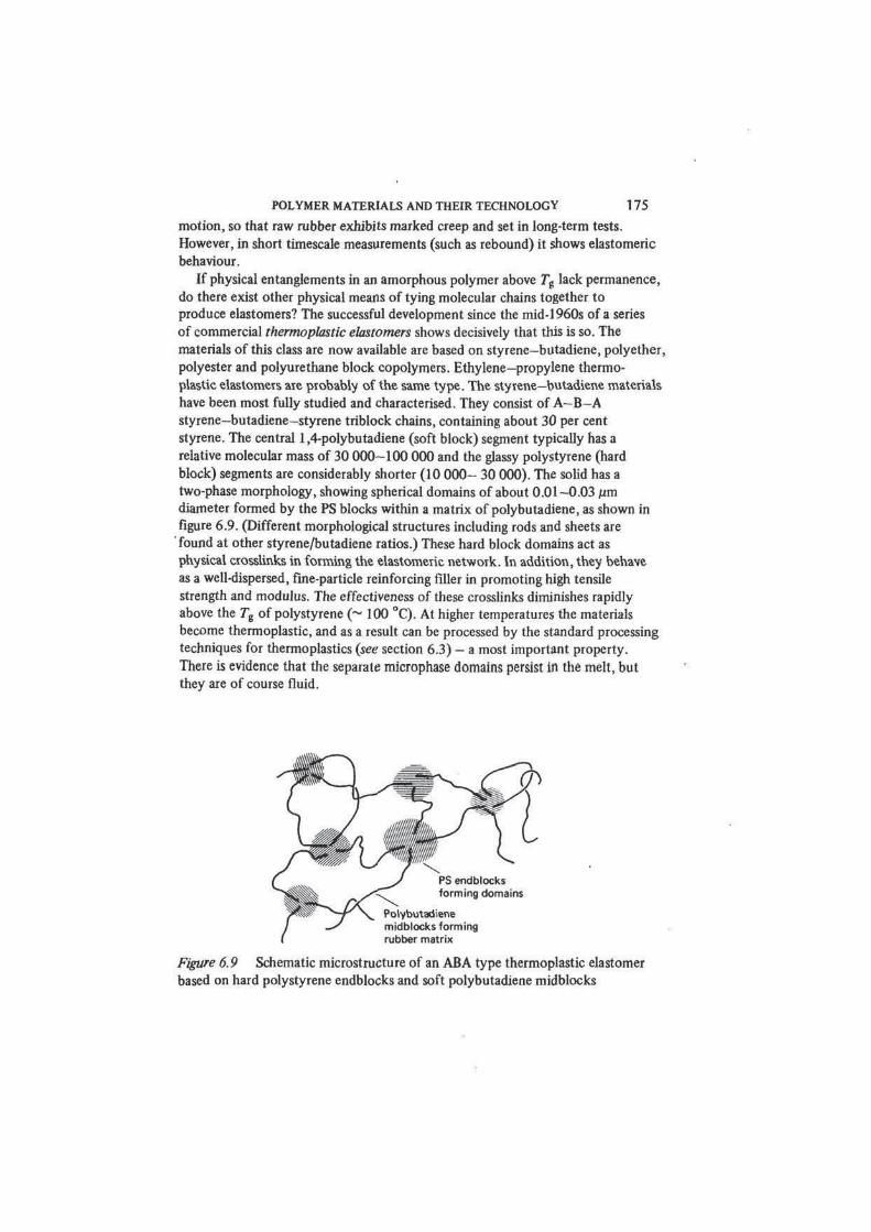
two-phase morphology, showing spherical domains of about 0.01-0.03 pm
diameter formed by the PS blocks within a matrix of polybutadiene, as shown in
figure 6.9. (Different morphological structures including rods and sheets are
found at other styrene/butadiene ratios.) These hard block domains act as
physical crosslinks in forming the elastomeric network. In addition, they behave
as a well-dispersed, fine-particle reinforcing filler in promoting high tensile
strength and modulus. The effectiveness of these crosslinks diminishes rapidly
above the 7"g of polystyrene (~ 100 °C). At higher temperatures the materials
become thermoplastic, and as a result can be processed by the standard processing
techniques for thermoplastics (see section 6.3) — a most important property.
There is evidence that the separate microphase domains persist in the melt, but
they are of course fluid.
Figure 6.9 Schematic microstructure of an ABA type thermoplastic elastomer
based on hard polystyrene endblocks and soft polybutadiene midblocks
176 POLYMER MATERIALS
6.6 Cellular Polymers
Cellular forms of many plastics and elastomers have been developed, largely
for their thermal and mechanical properties. The technology has been applied
most extensively to polyurethanes, polystyrene, polyvinyl chloride), polyethy-
lene, polypropylene, the phenolics, urea-formaldehyde resins, silicones, natural
rubber and SBR synthetic rubber. Both rigid and flexible cellular materials are
manufactured.
Most of the many processes for producing cellular polymer materials belong
to one of three groups.
(1) Those in which voids are formed by dispersing air in a polymer emulsion
or partially polymerised liquid by mechanical agitation.
(2) Those in which gas bubbles are formed within a liquid form of the
polymer, generally a melt or dispersion, by heating or by reduction of
pressure (the use of a physical blowing agent).
(3) Those in which gas bubbles are generated within the polymer liquid by a
chemical reaction (the use of a chemical blowing agent).
Methods of the first group are used to produce foam from NR and SBR
latices and also from UF prepolymer. Mechanical foaming generally produces
materials with an open-cell structure, which have high permeabilities to liquids
and gases. Methods of the second and third groups which employ blowing agents
provide finer control of cell structure and can be used to form open-cell or
closed-cell foams according to conditions. Closed-cell materials have much
higher elastic moduli in compression than similar open-cell foams as a result of
the presence of trapped air. Such materials also have excellent buoyancy and
barrier properties. The bulk of cellular polymers are manufactured by processes
which make use of blowing agents. Physical blowing agents are gases or volatile
liquids which may be dissolved in the polymer under pressure; on releasing the
pressure or on heating, the gas comes out of solution and forms bubbles, the size
of which can be controlled by fine-particle nucleating agents. Low density poly-
ethylene foams (30-160 kg/m3) are produced by such methods, commonly
using dichlorotetrafluoroethane as blowing gas. In a similar way cellular poly-
styrene materials are made by heating PS beads containing 4—8 per cent of a
volatile hydrocarbon such as n-pentane together with a nucleating agent. These
processes are particularly well suited to the production of foamed stock by
extrusion;.foaming occurs as the polymer emerges from the extruder nozzle and
the pressure acting on the extrudate falls.
Chemical blowing agents are substances which react with some component of
the polymer liquid or which decompose at suitable elevated temperatures to
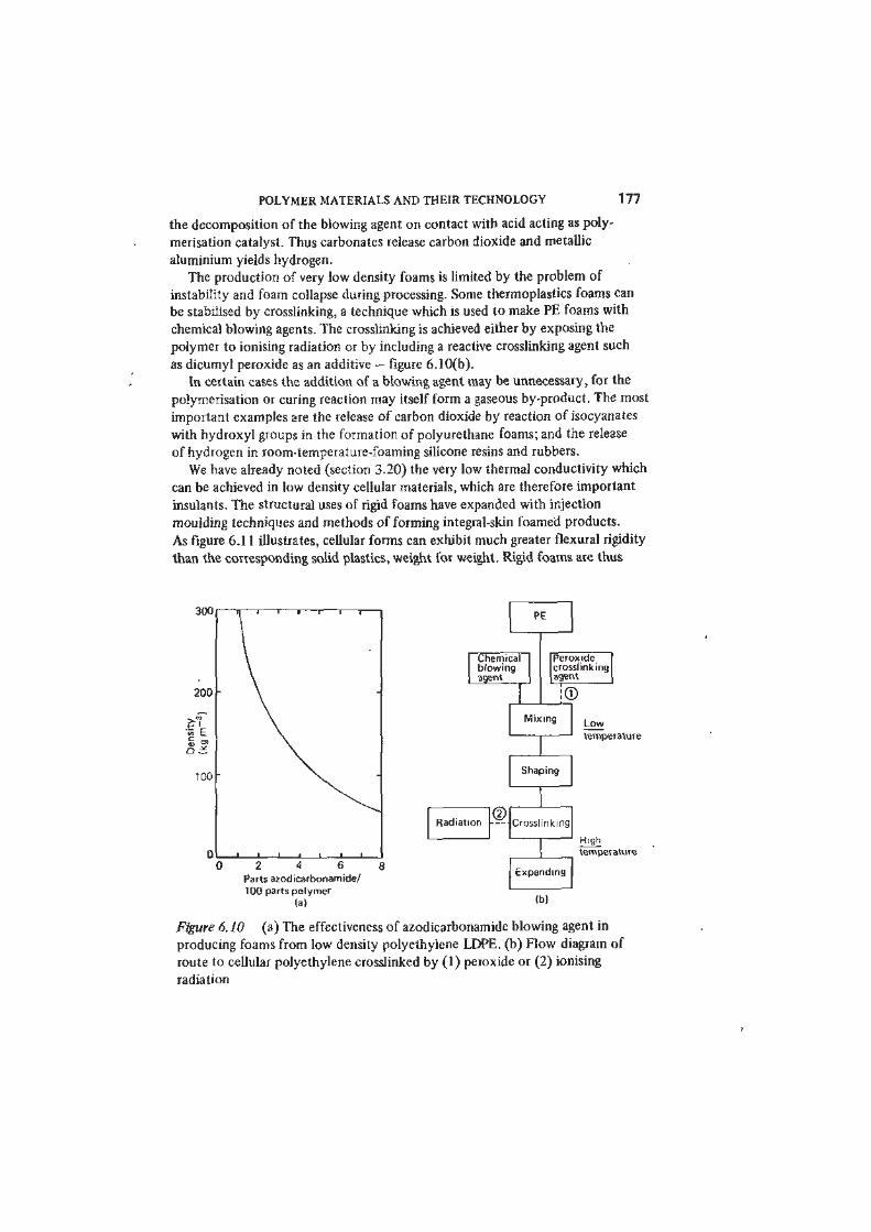
produce a gas. Azodicarbonamide H2NCON=NCONH2 is widely used; it
decomposes at about 195 °C to yield a mixture of the gases nitrogen and carbon
monoxide, with a little carbon dioxide. The total gas yield of 1 g of azodicarbon-
amide is about 230 cm3 at STP - figure 6.10(a). Phenolic resins are foamed by
POLYMER MATERIALS AND THEIR TECHNOLOGY 177
the decomposition of the blowing agent on contact with acid acting as poly-
merisation catalyst. Thus carbonates release carbon dioxide and metallic
aluminium yields hydrogen.
The production of very low density foams is limited by the problem of
instability and foam collapse during processing. Some thermoplastics foams can
be stabilised by crosslinking, a technique which is used to make PE foams with
chemical blowing agents. The crosslinking is achieved either by exposing the
polymer to ionising radiation or by including a reactive crosslinking agent such
as dicumyl peroxide as an additive — figure 6.10(b).
In certain cases the addition of a blowing agent may be unnecessary, for the
polymerisation or curing reaction may itself form a gaseous by-product. The most
important examples are the release of carbon dioxide by reaction of isocyanates
with hydroxyl groups in the formation of polyurethane foams; and the release
of hydrogen in room-temperature-foaming silicone resins and rubbers.
We have already noted (section 3.20) the very low thermal conductivity which
can be achieved in low density cellular materials, which are therefore important
insulants. The structural uses of rigid foams have expanded with injection
moulding techniques and methods of forming integral-skin foamed products.
As figure 6.11 illustrates, cellular forms can exhibit much greater flexural rigidity
than the corresponding solid plastics, weight for weight. Rigid foams are thus
JUU n i l l l l l
200
" \
« E £ a a* \
100
^ ^
0 i i i i i i i
PE
Chemicalblowingagenl
l ical I ing
L-J
Perox idecrosslinkingagent
!©Mix ing
Low
temperature
Shaping
®Radiation • - - Crosslinking
2 4 6
Parts azodicarbonamide/
100 parts polymer
(a)
Expanding
High
temperature
(b)
Figure 6. JO (a) The effectiveness of azodicarbonamide blowing agent in
producing foams from low density polyethylene LDPE. (b) Flow diagram of
route to cellular polyethylene crosslinked by (1) peroxide or (2) ionising
radiation
178 POLYMER MATERIALS
increasingly used in sandwich panel composites with steel, aluminium or solid
polymer facing sheets. Foamed elastomers (natural and synthetic rubbers and
polyurethanes) are highly compressible, resilient materials used widely for
gasketing, cushioning and sound and vibration damping.
6.7 Adhesives
Synthetic polymers have brought a great transformation in the technology of
adhesives. About four decades ago, adhesives were few: bituminous cements
and mastics; rubber cements; gelatine-based glues manufactured from hide,
hoof and bone; casein glues from milk protein; and polysaccharide glues
produced from vegetable starch. All these types had shortcomings. Bituminous
cements have a long history of use in building and civil engineering, but are
Density p
Load
W
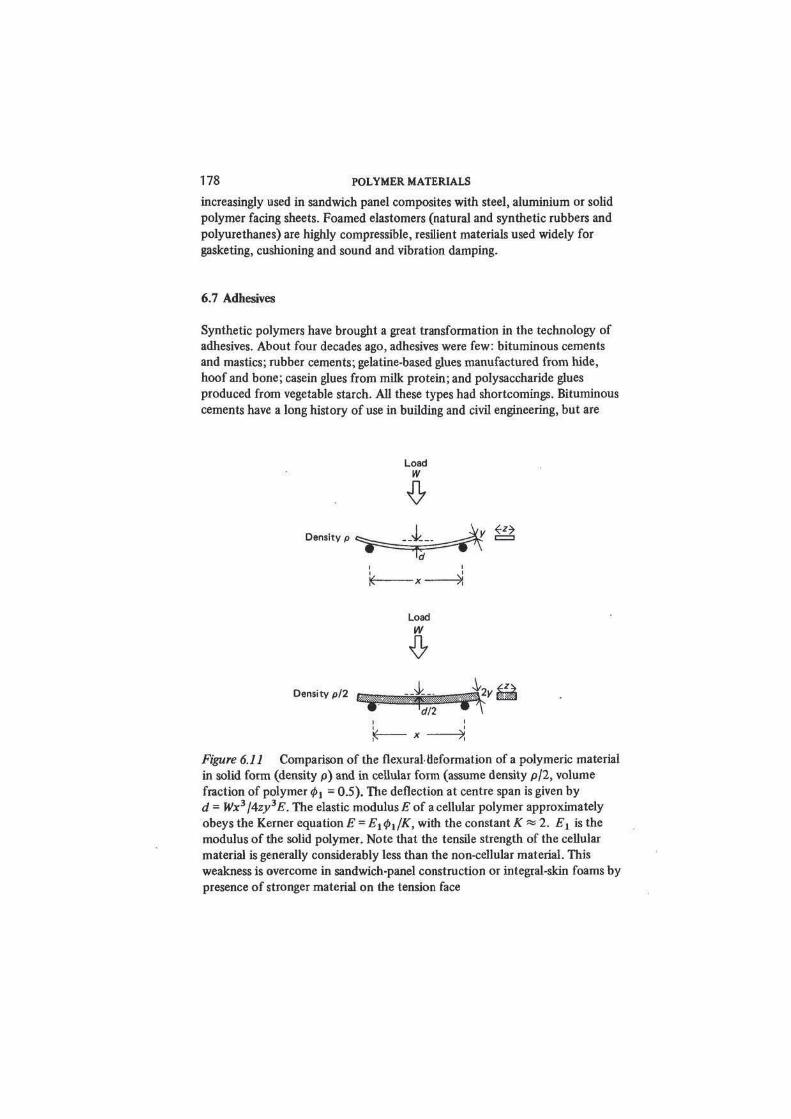
Figure 6.11 Comparison of the flexural deformation of a polymeric material
in solid form (density p) and in cellular form (assume density p/2, volume
fraction of polymer #j = 0.5). The deflection at centre span is given by
d = Wx3/4zy3E. The elastic modulus E of a cellular polymer approximately
obeys the Kerner equation E = Et <Pi/K, with the constant K « 2. Et is the
modulus of the solid polymer. Note that the tensile strength of the cellular
material is generally considerably less than the non-cellular material. This
weakness is overcome in sandwich-panel construction or integral-skin foams by
presence of stronger material on the tension face
Load
w
POLYMER MATERIALS AND THEIR TECHNOLOGY 179
subject to creep and soften seriously when warm. The animal and vegetable
glues are vulnerable to fungal attack and either dissolve or swell on contact with
water. Today however there is a great range of commercial adhesives (over 100
types and several thousand products are listed in the Adhesives Handbook) and
most of the principal thermoset and thermoplastic synthetic polymers and
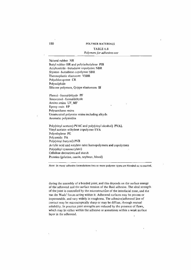
elastomers find some application In adhesive formulations. In table 6.8 therefore
we include only those polymers which have a major use as adhesives. Adhesive
formulations are of five general types;
(i) Solutions of thermoplastics (including unvulcanised rubbers) which bond
by loss of solvent.
(ii) Dispersions (emulsions) of thermoplastics in water or organic liquids
which bond by loss of the liquid phase.
(iii) Thermoplastics without solvents (hot-melt adhesives).
(iv) Polymeric compositions which react chemically after joint assembly to
form a crosslinked polymer (thermoset).
(v) Monomers which polymerise in situ.
Adhesives of types iv and v are converted by chemical reaction within the
assembled joint. Chemical bonding between the adhesive and the adherend has
sometimes been assumed; but adhesive bonding does not generally entail primary
chemical bond formation across the interface. The reaction usually involves only
components of the adhesive, which is cold-cured or heat-cured, with or without
pressure. Thermoset adhesives which evolve water during curing (such as phenolic
and amino resin types) usually require the application of pressure. Adhesives
which are sufficiently polar to show large dielectric losses at high frequency may
be successfully heat-cured by exposing the assembled joint to a radiofrequency
electric field. Dielectric heating is widely used in bonding wood with PF, MF and
UF adhesives. Cyanoacrylate adhesives are based on alkyl 2-cyanoacrylate
monomers such as
ICH2=CCOOCH3 methyl 2-cyanoacrylate
which polymerise extremely rapidly in the presence of traces of moisture
normally present on adherend surfaces. As noted in table 6.8, polymer hybrid
(two-polymer) adhesives are of considerable importance. Elastomers are added
to thermoset formulations to improve flexibility and impact resistance: examples
are EP-polysulphide, PF-CR and PF-NBR. PF-EP blends have exceptional
performance at temperatures up to 200 °C.
As the new adhesives have emerged the performance (especially the strength
and permanence) which can be achieved in adhesive-bonded structures has
greatly improved. The rational design of bonded joints has become a matter of
concern to design engineers; there has also been parallel progress in the under-
lying science of adhesion, so that the factors which control adhesive action are
becoming clear. It is essential that the adhesive should wet the adherend surface
180 POLYMER MATERIALS
TABLE 6.8
Polymers for adhesives use
Natural rubber NR
Butyl rubber I1R and polyisobutylene PIB
Acrylonitrile—butadiene copolymer NBR
Styrene—butadiene copolymer SBR
Thermoplastic elastomer YSBR
Polychloroprene CR
Polysulphide
Silicone polymers, Q-type elastomers SI
Phenol—formaldehyde PF
Resorcinol—formaldehyde
Amino resins UF, MF
Epoxy resin EP
Polyurethane resins
Unsaturated polyester resins including alkyds
Aromatic polyimides
Polyvinyl acetate) PVAC and polyvinyl alcohol) PVAL
Vinyl acetate-ethylene copolymer EVA
Polyethylene PE
Poly amide PA
Polyvinyl butyral) PVB
Acrylic acid and acrylate ester homopolymers and copolymers
Po!y(alkyl cyanoacrylate)
Cellulose derivatives and starch
Proteins (gelatine, casein, soybean, blood)
Note: In many adhesive formulations two or more polymer types are blended or co-reacted.
during the assembly of a bonded joint; and this depends on the surface energy
of the adherend and the surface tension of the fluid adhesive. The ideal strength
of the joint is controlled by the microstructure of the interfacial zone, and the
van der Waals' forces acting within it. Adherend surfaces may be porous or
impermeable, and vary widely in roughness. The adhesive/adherend line of
contact may be microscopically sharp or may be diffuse, through mutual
solubility. In practice joint strengths are reduced by the presence of flaws,
which may lie either within the adhesive or sometimes within a weak surface
layer in the adherend.
POLYMER MATERIALS AND THEIR TECHNOLOGY 181
6.8 Surface Coatings
The range of application of polymeric materials as coatings is vast: almost all
the major types of thermoplastics, thermosets and elastomers find use as coatings
in some form. In many of these applications, such as PVC extrusion coating of
wire or unsaturated polyester UP finishing of wood, the polymer materials and
methods of processing do not differ much from those we have discussed earlier
in this chapter. There is one major class of polymeric surface coating materials,
the paints and varnishes, which are sufficiently distinct to warrant separate
treatment. We devote this section to a brief survey of the science and technology
of paints and related materials, and the polymers on which they are based.
Paint manufacture is a very old-established industrial activity. In its early
phases its raw materials were exclusively natural in origin — natural oils, natural
resins and mineral pigments, from which paints and varnishes were produced by
blending and milling. The industry has been transformed in recent decades by
the availability of synthetic polymers, synthetic pigments and a wide range of
property-modifying additives. Materials of natural origin still find a place, but
a diminishing one, in modern paint formulations.
A paint is a suspension of solid pigment particles in a liquid phase (the vehicle)
which when applied to a surface dries to form a solid film. In the dried paint
film the pigment is dispersed in a continuous matrix (or binder) which is
invariably polymeric. Thus the vehicle is the liquid precursor of the binder. A
varnish is simply an unpigmented paint. The function of the surface coating may
be protective or decorative, or both; the polymeric binder is selected for a
variety of qualities, including strength, hardness and abrasion resistance over
a working range of temperature; weathering performance and resistance to
chemical attack; and optical properties such as refractive index and transparency.
Equally important are the properties of the liquid vehicle, which must be able to
form stable dispersions with pigment, be of suitable viscosity and show a
satisfactory rate of drying.
The binder materials which find use in paint formulations are very diverse,
and it is useful to classify them according to the nature of the film formation
process, or drying mechanism (see table 6.9). The simplest of these is evaporative
drying, class A. The vehicle may be a solution of a polymeric solid in an organic
solvent, and in such cases the wet film dries simply by loss of solvent to the air.
The so-called nitrocellulose lacquers (based on solutions of cellulose nitrate CN
in a solvent such as butyl acetate), chlorinated rubber dissolved in hydrocarbon
solvents, and acrylic lacquers based on plasticised PMMA and copolymers, are all
of this class. Also extremely important members are the emulsion or latex
paints, in which the vehicle is a two-phase mixture of finely dispersed particles
of polymer in water. Styrene—butadiene copolymers, poly(vinyl acetate) PVAC
and copolymers, and poly(methyl methacrylate) copolymers are the three main
kinds of polymer emulsion binder used. As the water evaporates from the wet
film the stability of the dispersion is destroyed and the particles of polymer
182 POLYMER MATERIALS
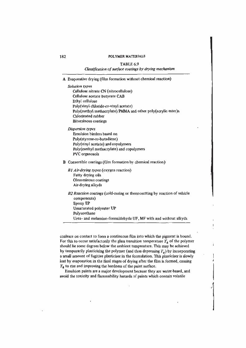
TABLE 6.9
Classification of surface coatings by drying mechanism
A Evaporative drying (fdm formation without chemical reaction)
Solution types
Cellulose nitrate CN (nitrocellulose)
Cellulose acetate butyrate CAB
Ethyl cellulose
Poly(vinyl chloride-co-vinyl acetate)
Poly(methyl methacrylate) PMMA and other poly(acrylic ester)s
Chlorinated rubber
Bituminous coatings
Dispersion types
Emulsion binders based on
Poly(styrene-co-butadiene)
Poly(vinyl acetate) and copolymers
Poly(methyl methacrylate) and copolymers
PVC organosols
B Convertible coatings (film formation by chemical reaction)
Bl Air-drying types (oxygen reaction)
Fatty drying oils
Oleoresinous coatings
Air-drying alkyds
B2 Reaction coatings (cold-curing or thermosetting by reaction of vehicle
components)
Epoxy EP
Unsaturated polyester UP
Polyurethane
Urea- and melamine-formaldehyde UF, MF with and without alkyds
coalesce on contact to form a continuous film into which the pigment is bound.
For this to occur satisfactorily the glass transition temperature Tg of the polymer
should lie some degrees below the ambient temperature. This may be achieved
by temporarily plasticising the polymer (and thus depressing Tg) by incorporating
a small amount of fugitive plasticiser in the formulation. This plasticiser is slowly
lost by evaporation in the final stages of drying after the film is formed, causing
Tg to rise and improving the hardness of the paint surface.
Emulsion paints are a major development because they are water-based, and
avoid the toxicity and flammability hazards of paints which contain volatile
POLYMER MATERIALS AND THEIR TECHNOLOGY 183
organic liquids. However, dispersion coatings are not exclusively water-based.
PVC (the homopolymer of which has low solubilities in common solvents) is
widely applied as a coating in the form of an organosol, a dispersion of PVC
particles (~ 0.1 Aim diameter) in organic liquids such as ketones. The 7"g of
PVC is about 80 °C so that heat is applied to bring about the formation of a
continuous film.
In surface coatings in which film formation is by evaporative drying, the
binder must be a thermoplastic since it must either be soluble or sinter as the
emulsion film dries. Amorphous polymers are, as a rule, more soluble than
crystalline and form transparent films, so that amorphous thermoplastics are
commonly found in surface coating binders. Straight PS is not a satisfactory
binder because it is brittle and lacks chemical resistance to solvents.
All other.drying mechanisms involve chemical reaction, although
simultaneous solvent loss may also occur. We can divide the chemically drying
paints into two subclasses, Bl and B2. In the first, the film-forming components
in the vehicle react with the oxygen in the air, or less commonly with water
vapour. This subclass contains the traditional paint formulations based on
natural fatly oils (such as linseed and soya and mostly of vegetable origin) and
natural resins, together with their more recent modifications. In all these paints
the reaction of the oils with atmospheric oxygen to produce crosslinked
network polymers lies at the heart of the film-forming process.
Table 6.10 summarises in simple outline the broad characteristics of these
complex materials and the paints made from them. The fatty oils themselves are
all mixtures of triglycerides of Cj 8 fatty acids, i.e. esters formed between the
alcohol glycerol and the long-chain acids which are denoted by HOOC *~ • .
There are many such acids (a few structures only are shown): they differ largely
in the number and position of the C=C bonds, which of course play a decisive
part in crosslinking the oil molecules during drying. As can be seen, linseed oil
(one of the leading paint oils) contains about 50 per cent of linolenic acid
which has three C=C bonds, 15 per cent of linoleic acid (with two C=C bonds)
and 20 per cent of oleic acid (with one C=C bond). On exposure to air, linseed
oil absorbs oxygen which initiates a series of free radical reactions, producing a
network polymer crosslinked through C-O—O—C, C—O—C and C—C primary
chemical bonds. Film formation in a paint or varnish may be speeded by partially
polymerising the oil before incorporating it into the vehicle, and assisted by
additives. In practice, oils are not generally used on their own as binders because
the resulting film lacks water resistance and strength. Traditional oleoresinous
paints and varnishes are based on mixtures of drying oils with various resins,
either natural (such as rosin or shellac) or synthetic (notably phenol-formalde-
hyde PF novolaks and resols). In some cases the resins react chemically with
the oil during the manufacture of the vehicle; in other cases the resins simply
dissolve in the oil. In both, oxidative drying of the fatty oil component leads to
the formation of a resin-containing film, which shows improvements in properties
such as drying speed, hardness or water resistance.
184 POLYMER MATERIALS
TABLE 6.10
Natural drying oils
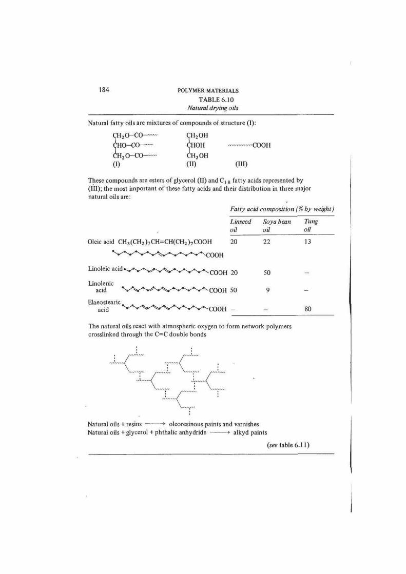
Natural fatty oils are mixtures of compounds of structure (I):
"H20-CO CH2OH
J H O - C O CHOH » — C O O H
: H 2 O - C O CH2OH
(I) (10 ( " 0
These compounds are esters of glycerol (II) and Cx 8 fatty acids represented by
(III); the most important of these fatty acids and their distribution in three major
natural oils are:
Fatty acid composition (% by weight)
Linseed
oil
Soya bean
oil
Tung
oil
Oleic acid CH3(CH2)7CH=CH(CH2)7COOH
Linoleic acid
Linolenicacid
Elaeostearic.
acid
20
COOH 20
•COOH 50
22
50
13
80
The natural oils react with atmospheric oxygen to form network polymers
crosslinked through the C=C double bonds
Natural oils + resins • oleoresinous paints and varnishes
Natural oils + glycerol + phthalic anhydride * alkyd paints
(see table 6.11)
POLYMER MATERIALS AND THEIR TECHNOLOGY 185
One chemical modification of the fatty drying oil binder deserves special
mention: this is a class of branched chain polyesters, known universally in the
coatings industry as alkyds, which have been outstandingly important in the
history of paint development. Air-drying alkyds are formed (table 6.11) from
fatty oils, additional glycerol and an organic acid or anhydride, such as phthalic
anhydride. Great variation is possible in the structures of alkyds according to
ingredients and synthesis conditions, but in essence esterification of the acid
and glycerol provides a polyester backbone along which the fatty oil chains are
attached. The subsequent crosslinking of these side chains through the reactive
C=C double bonds produces the insoluble network polymer film.
The other subclass of paints in table 6.9 which dry by chemical reaction is B2;
this includes all those coatings in which the solid film is formed by reaction
between components of the vehicle itself. B2 paints are thus mixed immediately
before they are applied to bring the reactive ingredients together, or else
converted by heat, ultraviolet light or electron beam irradiation and are based
essentially on thermoset formulations. Perhaps the most versatile are epoxy EP
and acrylic non-aqueous dispersion coatings, but urea-formaldehyde UF and
melamine-formaldehyde MF, unsaturated polyester UP and polyurethane types
are also of major importance. The formulations are diverse and complicated,
often involving copolymerisation with alkyds, and the details are outside the
scope of this account. However, they supply a wide range of factory -applied,
high performance finishes for innumerable manufactured products, including
automobiles and furniture.
We have discussed in outline the polymer materials which are used as paint
film formers. A complete paint formulation (such as that given in table 6.12 for
a PVAC copolymer emulsion coating) comprises binder and pigment as the main
components together with a number of additives which are incorporated to
modify properties, much as in compounding thermoplastics and elastomers.
Some indeed play the same roles: notably the plasticisers and stabilisers. The
pigment may have a decorative function but its presence also improves durability.
For paints for exterior use the pigment is a vital line of defence against photo-
degradation of the binder. Other additives control properties of the wet paint,
such as its flow characteristics, and the stability of the pigment-binder
dispersion or, in latex formulations, of the polymer emulsion.
We complete this section by considering briefly the optical and protective
functions of the dry pigmented film. A paint coating is frequently required to
obliterate the surface appearance of the substrate; the paint technologist speaks
of the hiding power of a paint as a figure of merit. The hiding power is a measure
of the dry film thickness needed to achieve a defined degree of obliteration,
usually determined by comparing the reflectance of overpainted black and
white test panels. The hiding action of a pigmented film arises from the multiple
scattering of incident light passing into it. Incident light is thus returned to the
surface, and beyond a certain thickness the paint film is opaque and incapable of
transmitting light to and from the surface of the substrate beneath. In the case
186 POLYMER MATERIALS
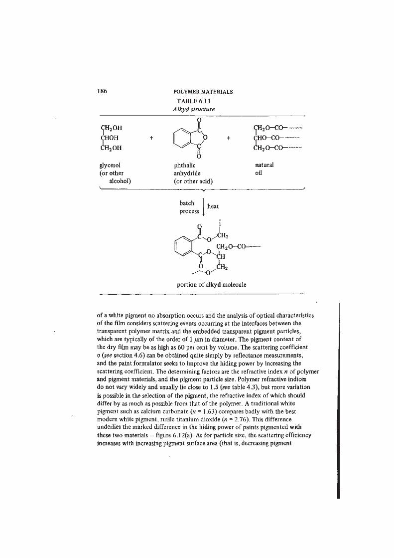
TABLE 6.11
Alkyd structure
CH2OH
CHOH
CH2OHP
CH20-CO-~
CHO-CO
CH 2 0-CO-
glycerol
(or other
alcohol)
phthalic
anhydride
(or other acid)
natural
oil
batch
process I heat
CH20-CO-
Isportion of alkyd molecule
of a white pigment no absorption occurs and the analysis of optical characteristics
of the film considers scattering events occurring at the interfaces between the
transparent polymer matrix and the embedded transparent pigment particles,
which are typically of the order of 1 /im in diameter. The pigment content of
the dry film may be as high as 60 per cent by volume. The scattering coefficient
a (see section 4.6) can be obtained quite simply by reflectance measurements,
and the paint formulator seeks to improve the hiding power by increasing the
scattering coefficient. The determining factors are the refractive index n of polymer
and pigment materials, and the pigment particle size. Polymer refractive indices
do not vary widely and usually lie close to 1.5 (see table 4.3), but more variation
is possible in the selection of the pigment, the refractive index of which should
differ by as much as possible from that of the polymer. A traditional white
pigment such as calcium carbonate (n = 1.63) compares badly with the best
modern white pigment, rutile titanium dioxide (n = 2.76). This difference
underlies the marked difference in the hiding power of paints pigmented with
these two materials — figure 6.12(a). As for particle size, the scattering efficiency
increases with increasing pigment surface area (that is, decreasing pigment
POLYMER MATERIALS AND THEIR TECHNOLOGY 187
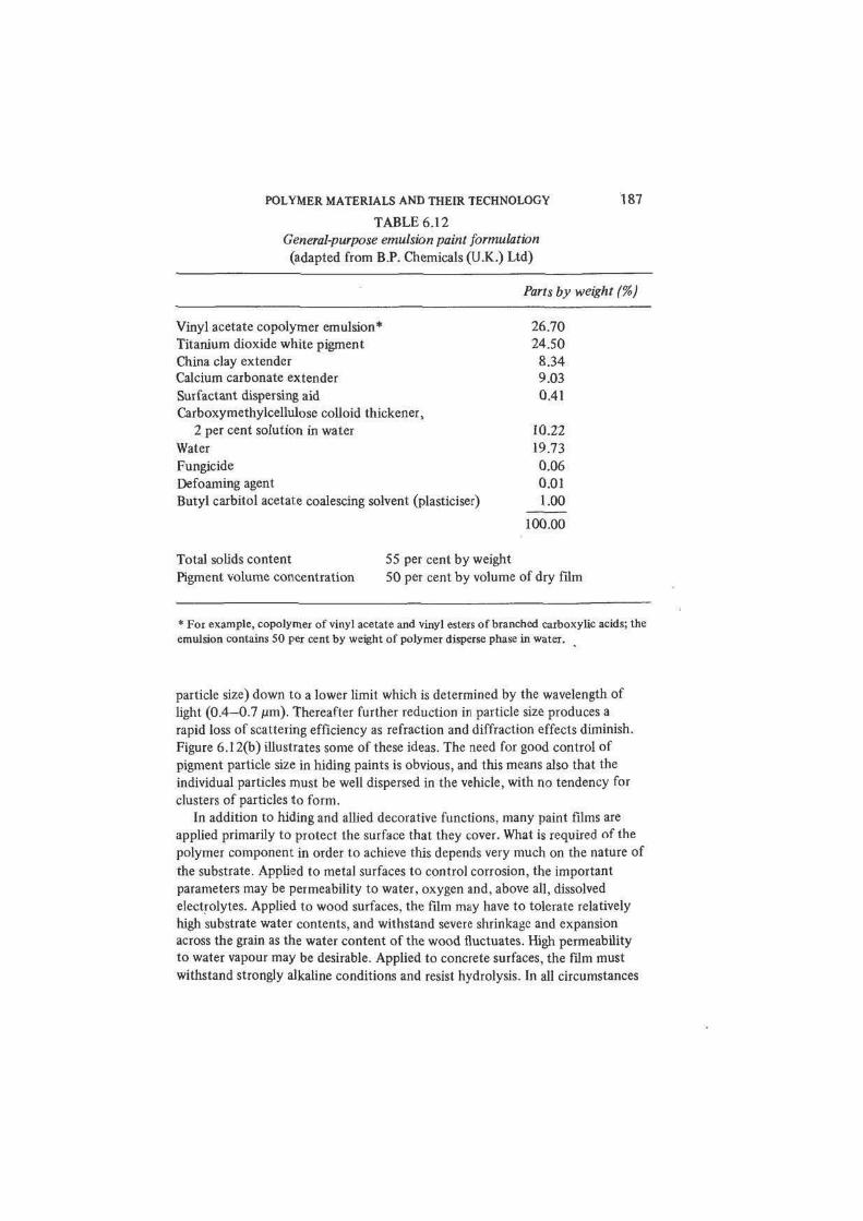
TABLE 6.12
General-purpose emulsion paint formulation
(adapted from B.P. Chemicals (U.K.) Ltd)
Parts by weight (%)
Vinyl acetate copolymer emulsion* 26.70
Titanium dioxide white pigment 24.50
China clay extender 8.34
Calcium carbonate extender 9.03
Surfactant dispersing aid 0.41
Carboxymethylcellulose colloid thickener,
2 per cent solution in water 10.22
Water 19.73
Fungicide 0.06
Defoaming agent 0.01
Butyl carbitol acetate coalescing solvent (plasticiser) 1.00
100.00
Total solids content 55 per cent by weight
Pigment volume concentration 50 per cent by volume of dry film
* For example, copolymer of vinyl acetate and vinyl esters of branched carboxylic acids; the
emulsion contains 50 per cent by weight of polymer disperse phase in water.
particle size) down to a lower limit which is determined by the wavelength of
light (0.4-0.7 /jm). Thereafter further reduction in particle size produces a
rapid loss of scattering efficiency as refraction and diffraction effects diminish.
Figure 6.12(b) illustrates some of these ideas. The need for good control of
pigment particle size in hiding paints is obvious, and this means also that the
individual particles must be well dispersed in the vehicle, with no tendency for
clusters of particles to form.
In addition to hiding and allied decorative functions, many paint films are
applied primarily to protect the surface that they cover. What is required of the
polymer component in order to achieve this depends very much on the nature of
the substrate. Applied to metal surfaces to control corrosion, the important
parameters may be permeability to water, oxygen and, above all, dissolved
electrolytes. Applied to wood surfaces, the film may have to tolerate relatively
high substrate water contents, and withstand severe shrinkage and expansion
across the grain as the water content of the wood fluctuates. High permeability
to water vapour may be desirable. Applied to concrete surfaces, the film must
withstand strongly alkaline conditions and resist hydrolysis. In all circumstances
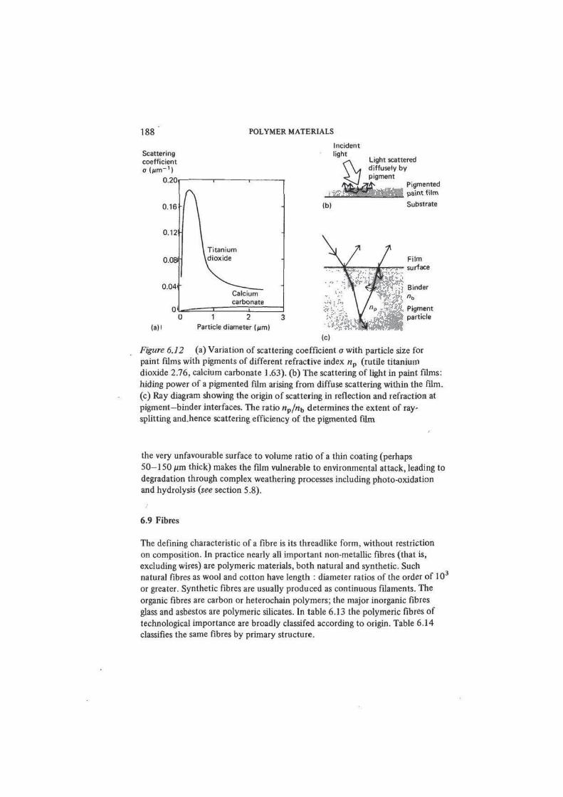
188 POLYMER MATERIALS
Scattering
coefficient
o l p m " ' |
0.20
0.16
Incident
light
0.04
0 '
Calcium
carbonate
(b)
Light scattered
diffusely by
pigment
Pigmented
ff paint film
Substrate
Film
surface
(a) i
1 2
Particle diameter iitm)
Pigment
particle
Figure 6.12 (a) Variation of scattering coefficient a with particle size for
paint films with pigments of different refractive index np (rutile titanium
dioxide 2.76, calcium carbonate 1.63). (b) The scattering of light in paint films:
hiding power of a pigmented film arising from diffuse scattering within the film.
(c) Ray diagram showing the origin of scattering in reflection and refraction at
pigment—binder interfaces. The ratio «p//ib determines the extent of ray-
splitting and.hence scattering efficiency of the pigmented film
the very unfavourable surface to volume ratio of a thin coating (perhaps
50-150 urn thick) makes the film vulnerable to environmental attack, leading to
degradation through complex weathering processes including photo-oxidation
and hydrolysis (see section 5.8).
6.9 Fibres
The defining characteristic of a fibre is its threadlike form, without restriction
on composition. In practice nearly all important non-metallic fibres (that is,
excluding wires) are polymeric materials, both natural and synthetic. Such
natural fibres as wool and cotton have length : diameter ratios of the order of 10
or greater. Synthetic fibres are usually produced as continuous filaments. The
organic fibres are carbon or heterochain polymers; the major inorganic fibres
glass and asbestos are polymeric silicates. In table 6.13 the polymeric fibres of
technological importance are broadly classifed according to origin. Table 6.14
classifies the same fibres by primary structure.
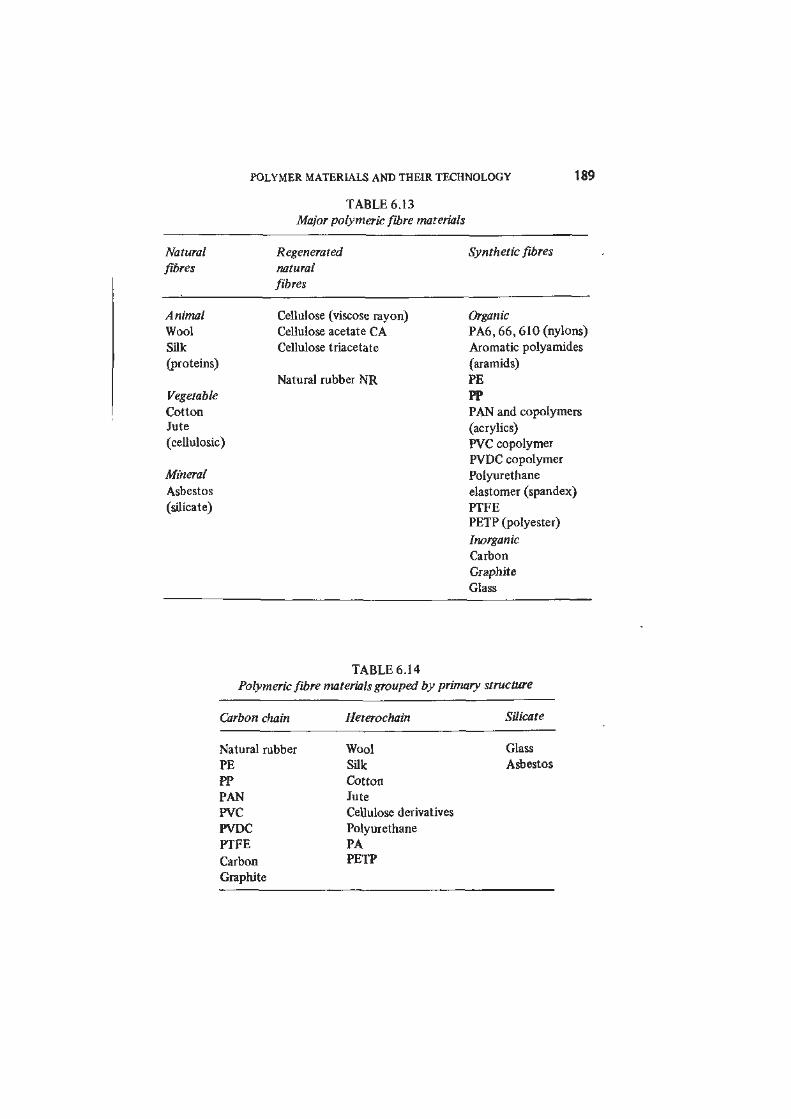
POLYMER MATERIALS AND THEIR TECHNOLOGY
TABLE 6.13
Major polymeric fibre materials
189
Natural Regenerated Synthetic fibres
fibres natural
fibres
Animal Cellulose (viscose rayon) Organic
Wool Cellulose acetate CA PA6,66,610 (nylons)
Silk Cellulose triacetate Aromatic polyamides
(proteins) (aramids)
Natural rubber NR PE
Vegetable PP
Cotton PAN and copolymersJute (acrylics)
(cellulosic) PVC copolymer
PVDC copolymer
Mineral Polyurethane
Asbestos elastomer (spandex)
(silicate) PTFE
PETP (polyester)
Inorganic
Carbon
Graphite
Glass
TABLE 6.14
Polymeric fibre materials grouped by primary structure
Carbon chain Heterochain Silicate
Natural rubber Wool Glass
PE Silk Asbestos
PP Cotton
PAN Jute
PVC Cellulose derivatives
PVDC Polyurethane
PTFE PA
Carbon PETP
Graphite
190 POLYMER MATERIALS
Fibres have two main uses — in the manufacture of textiles and in the
production of fibre-reinforced composites (see section 6.12); in addition, glass
fibres are of growing importance as the main element of optical cables. For all
these purposes fibre diameters are almost invariably small, rarely exceeding
25 (im. (For textile fibres, the linear density expressed in the units tex or denier
is usually quoted instead of diameter; tex = mg/m and tex = 9 denier.) The
value of fibres lies in collective properties which develop when they are combined
in large numbers in various fibre assemblies such as yarns, woven, knitted or
bonded fabrics, or composites in combination with a variety of matrices. Hence
there have evolved several technologies which deal with manufacturing and
processing fibres of many kinds for particular end-uses. The details of textile
technology and fibre-reinforced plastics technology lie outside the scope of this
book but, of course, their products are major outlets for polymer materials.
For most textiles the fibre must possess both a high tensile strength (100-600
MN/m2) and an extension at break in the range 5-50 per cent - figure 6.13(a).
Such mechanical properties in the fibres are necessary for the fabrics produced
from them to exhibit the desirable properties of strength and flexibility which
are subtly embodied in attributes such as drape. In addition, textile fibres must
possess a suitable assortment of chemical characteristics to ensure that they can
be dyed, and show reasonable resistance to weathering and other kinds of
degradation. The textile technologist pays particular attention to the absorption
of water by fibres and to any changes in properties which result from moisture
uptake. These changes underlie such characteristics of the fabric as resistance to
shrinkage and creasing, and drying speed. The fire performance of textiles is of
great practical interest, and finally triboelectric charging is a serious problem
both during manufacture and in use.
In practice these diverse requirements are met by a number of crystalline
partially oriented polymers, into which class all the leading textile fibres fall. In
natural fibres such as cotton and wool the orientation of the polymer chains
arises from the organisation imposed during growth by the synthesising enzymes.
In cotton each fibre is an individual cell, which contains microfibrils arranged
helically about the fibre axis and each comprising about 40 cellulose polymer
chains. The cellulose chains are long, with a relative molecular mass of about
5 x 10s, corresponding to about 9000 six-atom rings in the chain backbone.
They adopt a hydrogen-bonded crystalline arrangement within the microfibrils.
The individual fibre of wool in contrast comprises many individual cells and is
more highly structured than that of cotton. The principal polymer components
are a number of proteins known collectively as keratin. Once again however
crystalline microfibrils exist within the fibre, lying parallel to the fibre axis.
Within each microfibril the keratin adopts the a-helix conformation found
widely in proteins and proposed by Pauling and Corey in 1951.
By contrast, synthetic fibres are produced as continuous filaments, spun
either from the melt or from a solution. The initial morphology of the emergent
fibre depends on the rate of cooling in melt spinning, on the conditions of
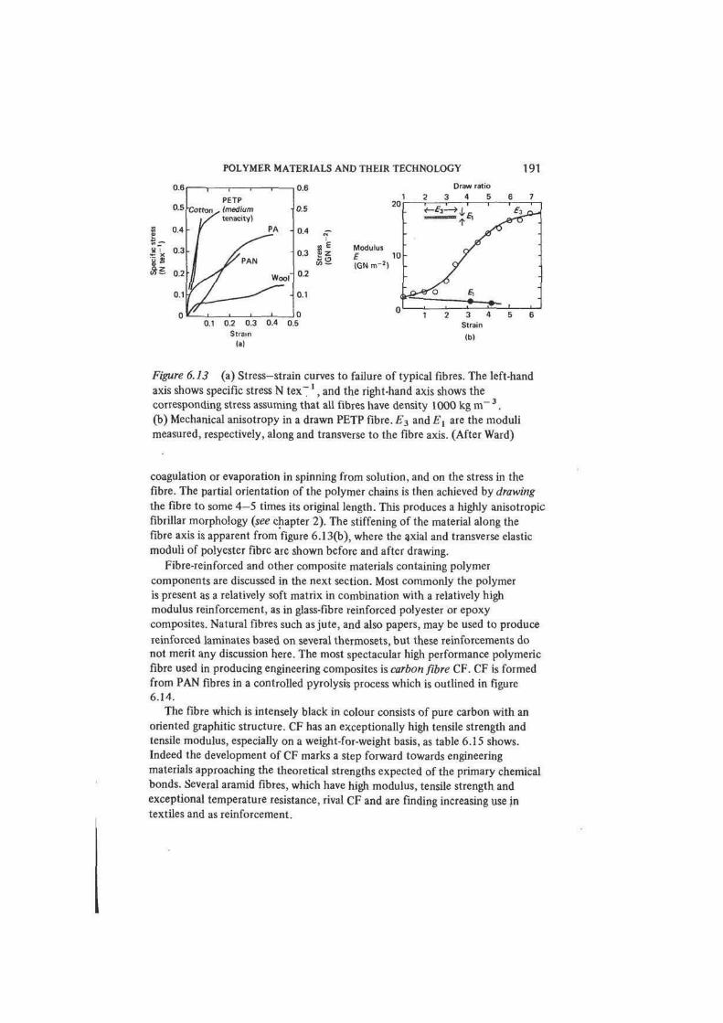
POLYMER MATERIALS AND THEIR TECHNOLOGY 191
U.b
0.5
1
Cot ton ,
PETP
„ (medium
tenacity)
O.b
0.5
0.4 PA . 0.4I
1 0.3
#PAN0.3
as£ 0.2
0.1
0
Woof
1
0.2
0.1
05
0.2
0.1
00.1 0.2 0.3 0.4 0
0.2
0.1
05
Strain
(a)
Figure 6.13 (a) Stress-strain curves to failure of typical fibres. The left-hand
axis shows specific stress N tex7 ' , and the right-hand axis shows the
corresponding stress assuming that all fibres have density 1000 kg m_ 3 .
(b) Mechanical anisotropy in a drawn PETP fibre. E3 and Ex are the moduli
measured, respectively, along and transverse to the fibre axis. (After Ward)
coagulation or evaporation in spinning from solution, and on the stress in the
fibre. The partial orientation of the polymer chains is then achieved by drawing
the fibre to some 4 - 5 times its original length. This produces a highly anisotropic
fibrillar morphology (see chapter 2). The stiffening of the material along the
fibre axis is apparent from figure 6.13(b), where the axial and transverse elastic
moduli of polyester fibre arc shown before and after drawing.
Fibre-reinforced and other composite materials containing polymer
components are discussed in the next section. Most commonly the polymer
is present as a relatively soft matrix in combination with a relatively high
modulus reinforcement, as in glass-fibre reinforced polyester or epoxy
composites. Natural fibres such as jute, and also papers, may be used to produce
reinforced laminates based on several thermosets, but these reinforcements do
not merit any discussion here. The most spectacular high performance polymeric
fibre used in producing engineering composites is carbon fibre CF. CF is formed
from PAN fibres in a controlled pyrolysis process which is outlined in figure
6.14.
The fibre which is intensely black in colour consists of pure carbon with an
oriented graphitic structure. CF has an exceptionally high tensile strength and
tensile modulus, especially on a weight-for-weight basis, as table 6.15 shows.
Indeed the development of CF marks a step forward towards engineering
materials approaching the theoretical strengths expected of the primary chemical
bonds. Several aramid fibres, which have high modulus, tensile strength and
exceptional temperature resistance, rival CF and are finding increasing use in
textiles and as reinforcement.
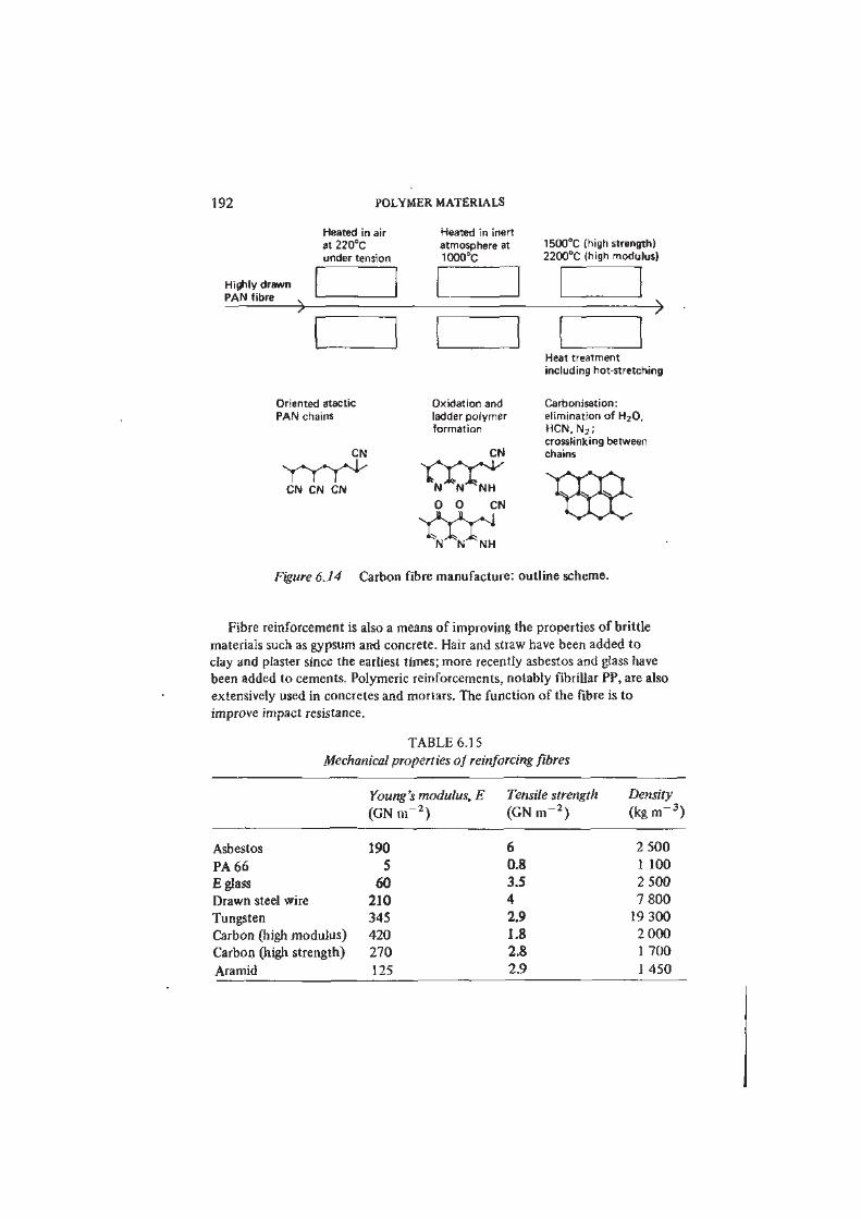
192 POLYMER MATERIALS
Heated in air
at 220°C
under tension
Highly drawn
PAN fibre
Heated in inert
atmosphere at
1000°C
1500°C (high strength)
2200°C (high modulus)
">
Heat treatment
including hot stretching
Oriented atactic
PAN chains
CN
CN CN CN
Oxidation and
ladder polymer
formation
CN
0 0 CN
tec
Carbonisation:
elimination of HjO,
HCN, N 2 ;
crosslinking between
chains
Figure 6.14 Carbon fibre manufacture: outline scheme.
Fibre reinforcement is also a means of improving the properties of brittle
materials such as gypsum and concrete. Hair and straw have been added to
clay and plaster since the earliest times; more recently asbestos and glass have
been added to cements. Polymeric reinforcements, notably fibrillar PP, are also
extensively used in concretes and mortars. The function of the fibre is to
improve impact resistance.
TABLE 6.15
Mechanical properties of reinforcing fibres
Young's modulus, E Tensile strength Density
(GN m" 2 ) (GNrrf• * )
(kgm- 3 )
Asbestos 190 6 2 500
PA 66 5 0.8 1 100
E glass 60 3.5 2 500
Drawn steel wire 210 4 7 800
Tungsten 345 2.9 19 300
Carbon (high modulus) 420 1.8 2 000
Carbon (high strength) 270 2.8 1 700
Aramid 125 2.9 1 450
POLYMER MATERIALS AND THEIR TECHNOLOGY
6.10 Water-soluble Polymers
193
Most synthetic polymer materials are insoluble in water and this is usually seen
as a virtue. In some circumstances, water solubility can be put to use and some
of the main groups of water-soluble polymers are listed in table 6.16. Water-
soluble natural polymers are numerous. Some degree of chemical bond polarity
must be present for a polymer to be soluble in water but the controlling factors
are subtle. Thus, for example, polyethylene and polyoxymethylene are insoluble
whereas poly(ethylene oxide) is highly soluble. Celluloses are insoluble while
starches (which are structurally similar polysaccharides) are soluble. Broadiy,
carbon chain linear polymers are only water soluble if there are polar oxygen
or nitrogen-containing sidegroups attached to about one-half of the C atoms
of the main chain. In water, as in other solvents, polymer solubility is
frequently limited by phase separation above or below a critical temperature;
dissolved polymers are also often precipitated by addition of salts.
Since this book deals with solid polymers, the interest in water-soluble
polymers lies in particular applications where the water solubility is exploited
either in processing or as an end-use property. For example, polyacrylamide
may be chemically crosslinked to form an insoluble gel; the polymer is used in
stabilising large soil structures, the polymer being injected as a low viscosity aqueous
solution and then converted into a gel in situ by a chemically retarded crosslinking
reaction. Another example of a polymer material passing through an aqueous
solution stage is in the use of poly(acrylic acid)/glass dental cements. The
polymer component crosslinks in situ by chemical reaction with metal ions
leached from the glass filler to form an insoluble network. In contrast, many
pharmaceutical products make use of water-soluble polymers, for example in
tablet coating and encapsulation, to control the release of drugs in the body.
Most commercial applications of water-soluble polymers are in modifying
fluid properties rather than as solid materials.
6.11 Films and Membranes
As films and membranes, synthetic polymer materials have no competitors.
Most of the polymer films used today, for example in medicine, packaging and
photography, meel needs which could not be met by metals, ceramics or even
natural polymers. Several applications provide extremely interesting examples of
polymer materials science at work and we discuss two in this section.
Co-extruded Barrier Films
We showed in section 5.2 that the permeability of different polymers to gases
and vapours varies greatly. Furthermore the mechanical properties of polymer
films also differ greatly. Figure 6.15 illustrates an important innovation in film
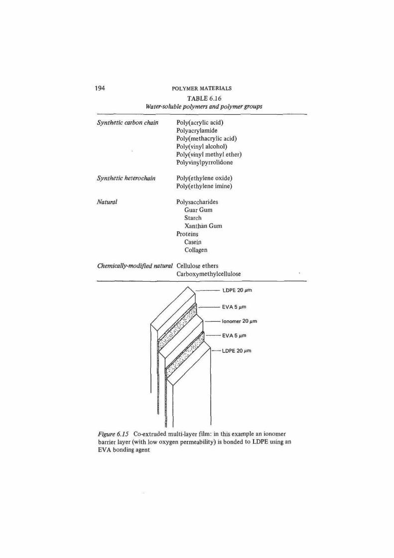
194 POLYMER MATERIALS
TABLE 6.16
Water-soluble polymers and polymer groups
Synthetic carbon chain Poly(acrylic acid)
Polyacrylamide
Poly(methacrylic acid)
Polyvinyl alcohol)
Polyvinyl methyl ether)
Polyvinylpyrrolidone
Synthetic heterochain Poly(ethylene oxide)
Poly(ethylene imine)
Natural Polysaccharides
Guar Gum
Starch
Xanthan Gum
Proteins
Casein
Collagen
Chemically-modified natural Cellulose ethers
Carboxymethylcellulose
LDPE 20 urn
EVA 5 iim
lonomer 20 Mm
EVA 5 jim
LDPE20 Mm
Figure 6.15 Co-extruded multi-layer film: in this example an ionomer
barrier layer (with low oxygen permeability) is bonded to LDPE using an
EVA bonding agent
POLYMER MATERIALS AND THEIR TECHNOLOGY 195
technology: the co-extrusion of several different polymer films into a multi-
layer composite. Co-extruded composite films are finding wide application in
the packaging of food and medical products.
Separation Membranes: Desalination and Dialysis
The two largest uses of polymer membranes for separation of mixtures are in
the desalination of water and in medical dialysis. Desalination of seawater and
brackish water is commonly carried out by reverse osmosis using cellulose acetate
membranes. The CA membrane is permeable to water (via pores a few nm in
diameter) but highly impermeable to dissolved salts. In addition to the perm-
selectivity, the membrane must be sufficiently strong to resist the pressure
applied across it to generate the reverse osmotic flow (at least 20 aim) and be
stable against hydrolysis and biological attack. In the case of CA, these two
forms of degradation are controlled effectively by operating near neutral pH. In
blood dialysis, membranes of regenerated cellulose are used to separate impurities
such as urea (which diffuse through the membrane) from macromolecular blood
constituents (which do not). In this use, the lack of toxicity and inertness
towards biochemically active macromolecules are critical requirements.
6.12 Composites
We have made passing references earlier in this chapter to the importance in
polymer technology of combinations of plastics materials with reinforcing fibres
and sheet materials. Such combinations are examples of composite materials. The
mechanics of composite solids has received much attention from engineers and
scientists in recent years. The many studies, both theoretical and experimental,
of composite behaviour in solids establish a general framework for understanding
deformation and fracture in such materials. This emerging theory extends to a
much wider range of materials than polymer composites alone, and embraces
also materials as diverse as concrete, fibre-reinforced cements and metals, as well
as natural substances like wood and bone.
The fibre-reinforced plastics have played an important part in stimulating this
activity. The geometrical simplicity of a fibre (or a parallel bundle of fibres)
embedded in a polymer matrix was amenable to analysis and this pointed the
way to the mechanics of more complex materials. Several texts listed at the end
of this chapter provide a comprehensive account of composite mechanics.
However, the subject lies beyond the scope of this book.
The important polymer-based composites are numerous. Plywoods, which are
laminates of wood veneer bonded with PF and amino resins, are extremely
successful commercial materials; PF resins are also used in making particle boards
from wood waste. Glass-fibre reinforced unsaturated polyesters and epoxies are
the major fibre-reinforced polymer materials, with uses which include both
commodity products and high performance engineering.
196 POLYMER MATERIALS
Suggestions for Reading
Engineering Thermoplastics
Bucknall, C. B.( Toughened Plastics (Applied Science, London, 1977).
Clagett, D. C, 'Engineering plastics', in Encyclopaedia of Polymer Science and
Engineering, vol. 6,2nd edn, pp. 94-131 (Wiley, New York, 1986).
Margolis, J. M. (Ed.), Engineering Thermoplastics: Properties and Applications
(Dekker, New York, 1985).
Manson, J. A. and Sperling, L. H., Polymer Blends and Composites (Heyden,
London, 1976).
Ogorkiewicz, R. M.(Ed.), Thermoplastics: Properties and Design (Wiley, London,
1974).
Ogorkiewicz, R. M., The Engineering Properties of Plastics, Engineering Design
Guide no. 17 (Oxford University Press, 1977).
Powell, P. C , The Selection and Use of Thermoplastics, Engineering Design
Guide no. 19 (Oxford University Press, 1977).
Riess, G., Hurtrez, G. and Bahadur, P., 'Block copolymers', in Encyclopaedia of
Polymer Science and Engineering, vol. 2, pp. 324-434 (Wiley, New York,
1985).
Rodriguez, F., Principles of Polymer Systems, 2nd edn (McGraw-Hill, New
York, 1983).
Tess, R. W. and Poehlein, G. W. (Eds), Applied Polymer Science, 2nd edn
(American Chemical Society, Washington DC, 1985).
Material Property Data
Brandrup, J. and Immergut, E. H. (Eds), Polymer Handbook, 2nd edn (Wiley,
New York, 1975).
Brydson, J. A., Plastics, 4th edn (Butterworth, London, 1982).
Encyclopaedia of Polymer Science and Engineering (Wiley, New York, 1985
onwards) [formerly Encyclopaedia of Polymer Science and Technology].
Kroschwitz, J. I. (Ed.), Polymers: An Encyclopedic Sourcebook of Engineering
Properties (Wiley, New York, 1987).
Modern Plastics Encyclopaedia (McGraw-Hill, New York, annual).
Saechtling, H., International Plastics Handbook (Hanser, Munich, 1987).
Standards and Testing
ASTM, Annual Book of ASTM Standards, Section 8, Plastics; Section 9, Rubbers
(American Society for Testing and Materials, Philadelphia, Pa., annual)
BS 2782, Methods of Testing Plastics (British Standards Institution, London).
BS 4618, Recommendations for the Presentation of Plastics Design Data (British
Standards Institution, London).
POLYMER MATERIALS AND THEIR TECHNOLOGY 197
See also standards issued by the International Organization for Standardization
(ISO), Geneva (Technical Committees 61, Plastics; and 45, Rubbers).
Brown, R. P. (Ed.), Handbook of Plastics Test Methods, 2 nd edn (Godwin,
London, 1981).Brown, R. P., Physical Testing of Rubbers, 2nd edn (Elsevier Applied Science,
London, 1986).
Brown, R. P. and Read, B. E. (Eds), Measurement Techniques for Polymeric
Solids (Applied Science, London, 1984).
Kampf, G., Characterization of Plastics by Physical Methods (Hanser, Munich,
1986).
Shah, V., Handbook of Plastics Testing Technology, (Wiley, New York, 1984).
Additives
Gaechter, R. and Mueller, H. (Eds), Plastics Additives Handbook (Hanser,
Munich, 1985).
Mascia, L., The Role of Additives in Plastics (Edward Arnold, London, 1974).
Ritchie.P. D. (Ed.), Plasticizers, Stabilizers and Fillers (Iliffe, London, 1972).
Sears, J. K. and Darby, J. R., The Technology of Plasticisers (Wiley, New York,
1982).
Processing
Becker, W. E., Reaction Injection Moulding (Van Nostrand Reinhold, New
York, 1979).Bikales, N. M. (Ed.), Extrusion and Other Plastics Operations (Wiley-Inter-
science,New York, 1971).
Bown, J. and Robinson, J. D., 'Injection and transfer moulding and plastics
mould design', Manual of Light Production Engineering, vol. 1 (Business
Books, London, 1970).
Dubois, J. H. and John, F. W.,Plastics, 5th edn (Van Nostrand Reinhold, New
York, 1974).
Fisher, E. G., Blow Moulding (Iliffe, London, 1971).
Fisher, E. G., Extrusion of Plastics, 3rd edn (Newnes-Butterworth, London,
1976).Frados, J. (Ed), Plastics Engineering Handbook, 4th edn, Society of the Plastics
Industry (Van Nostrand Reinhold, New York, 1976).
Irwin, C , 'Blow molding', in Encyclopaedia of Polymer Science and Engineering,
vol. 2,2nd edn, pp. 447-478 (Wiley, New York, 1985).
Kaufman, H. S. and Falcetta, J. F. (Eds), An Introduction to Polymer Science
and Technology, chs 9-11 (Wiley, New York, 1977).
Kircher, K., Chemical Reactions in Plastics Processing (Hanser, Munich, 1987).
Kobayashi, A., Machining of Thermoplastics (McGraw-Hill, New York, 1967).
198 POLYMER MATERIALS
Kruder,G. A., 'Extrusion', in Encyclopaedia of Polymer Science and Engineering,
vol. 6,2nd edn, pp. 571-631 (Wiley, New York, 1986).
Meyer, R. W'., Handbook of'Pultrusion Technology (Chapman and Hall, London,
1985).
Middleman, S., Fundamentals ofPolymer Processing (McGraw-Hill, New York,
1977).
Pearson, J. R. A., Mechanics of Polymer Processing (Elsevier Applied Science,
London, 1985).
Postans, J. H., Plastics Mouldings, Engineering Design Guide no. 24 (Oxford
University Press, 1978).
Rubin, 1.1., Injection Moulding Theory and Practice (Wiley, New York, 1973).
Rubin, 1.1., 'Injection molding', in Encyclopaedia ofPolymer Science and
Engineering, vol. 8,2nd edn, pp. 102-138 (Wiley, New York, 1987).
Tadmor, Z. and Gogos, C. G., Principles of Polymer Processing (Wiley, New
York, 1979).
Throne, J. L., Thermoforming (Hanser, Munich, 1987).
Thermosets
Bruins, P. F. (Ed.), Unsaturated Polyester Technology (Gordon and Breach,
New York, 1976).
May, C. A. and Tanaka, Y., Eppxy Resins: Chemistry and Technology (Dekker,
New York, 1973).
Whelan, A. and Brydson, J. A. (Eds), Developments in Thermosetting Plastics
(Applied Science, London, 1975).
Whitehouse, A. A. K., Pritchett, E. G. K. and Barnett, G., Phenolic Resins, 2nd
edn (Iliffe, London, 1967).
Elastomers
Barnard, D. et al., 'Natural rubber', in Encyclopaedia ofPolymer Science and
Technology, vol. 12, pp. 178-256 (Wiley, New York, 1970).
Blackley, D. C, Synthetic Rubbers: their Chemistry and Technology (Applied
Science, London, 1983).
Blow, C. M., and Hepburn, C. (Ed), Rubber Technology and Manufacture, 2nd
edn (Butterworth, London, 1982).
Cooper, W., 'Synthetic elastomers', in Encyclopaedia of Polymer Science and
Technology, vol. 5, pp. 406-482 (Wiley, New York, 1966).
Eirich, F. R. (Ed.), Science and Technology of Rubber (Academic Press,
New York, 1978).
Garvey, B. S. Jr, 'Rubber compounding and processing', in Encyclopaedia of
Polymer Science and Technology, vol. 12, pp. 280-304 (Wiley, New York,1970).
POLYMER MATERIALS AND THEIR TECHNOLOGY 199
Morton, M. (Ed.), Rubber Technology (Van Nostrand Reinhold, New York,
1973).
Saltman, W. M., The Stereo Rubbers (Wiley, New York, 1977).
Cellular Plastics
Frisch, K. C. and Saunders, J. H. (Eds), Plastic Foams, 2 vols (Dekker, New
York, 1972).
Shutov, F. A., 'Foamed polymers, cellular structure and properties' in
Advances in Polymer Science, vol. 51, Industrial Developments, pp. 155-218
(Springer, Berlin, 1983).
Shutov, F. A., Integral/Structural Polymer Foams: Technology, Properties and
Applications (Springer, Berlin, 1986).
Suh, K. W. and Webb, D. D.;'Cellular materials', in Encyclopaedia of Polymer
Science and Engineering, vol. 3,2nd edn, pp. 1-59 (Wiley, New York, 1985).
Adhesives
Bikales, N. M. (Ed.), Adhesion and Bonding (Wiley-Interscience, New York,
1971).
Kaelble, D. H., Physical Chemistry of Adhesion (Wiley-Interscience, New York,
1971).
Kinloch, A. J. (Ed.) Durability of Structural Adhesives (Elsevier Applied
Science, London, 1983)
Kinloch, A. J. (Ed.), Structural Adhesives: Developments in Resins and
Primers (Elsevier Applied Science, London, 1986).
Kinloch, A. J., Adhesion and Adhesives: Science and Technology (Chapman
and Hall, London, 1987).
Shields, J., Adhesive Bonding, Engineering Design Guide no. 2 (Oxford
University Press, 1974).
Shields, J., Adhesives Handbook, 3rd edn (Butterworth, London, 1984).
Skeist, I. (Ed.), Handbook of Adhesives, 2nd edn (Van Nostrand Reinhold,
New York, 1977).
Wake, W. C , Adhesion and the Formulation of Adhesives, 2nd edn (Applied
Science, London, 1982).
Coatings
Nylen, P. and Sunderland, E., Modern Surface Coatings (Wiley, London, 1965).
Turner, G. P. A., Introduction to Paint Chemistry, 2nd edn (Chapman and Hall,
London, 1980).
Films and Membranes
Kesting, R. E., Synthetic Polymeric Membranes: a Structural Perspective, 2nd
edn (Wiley, New York, 1985).
200 POLYMER MATERIALS
Water-soluble Polymers
Davidson, R. L. (Ed.), Handbook of Water-Soluble Gums and Resins (McGraw-
Hill, New York, 1980).
Finch, C. A. (Ed.), Chemistry and Technology of Water-Soluble Polymers (Plenum, New York, 1983).
Molyneux, P., Water-Soluble Synthetic Polymers: Properties and Behaviour,
2 vols (CRC Press, Baton Roca, Fla., 1983).
Fibres and Composites
Berlin, A. A., Volfson, S. A., Enikolopian, N. S. and Negmatov, S. S. (Eds),
Principles of Polymer Composites (Springer, Berlin, 1986).
Clegg, D. W. and Collyer, A. A. (Eds), Mechanical Properties of Reinforced
Thermoplastics (Elsevier Applied Science, London, 1986).
Dietz, A. G. H. (Ed.), Composite Engineering Laminates (MIT Press, Boston,
Mass., 1969).
Friedrich, K., Fracture Mechanical Behaviour of Short Fiber Reinforced
Thermoplastics (VDI-Verlag, Dusseldorf, 1984).
Gill, R. M., Carbon Fibres in Composite Materials (Iliffe, London, 1972).
Hull, D., Introduction to Composite Materials (Cambridge University Press,
1981).
Katz, H. S. and Milewski, J. V.,Handbook of Fillers and Reinforcements for
Plastics (Van Nostrand Reinhold, New York, 1978).
Langley, M. (Ed.), Carbon Fibres in Engineering (McGraw-Hill, London, 1973).
Lewin, M. and Pearce, E. M. (Eds), Fiber Chemistry, Handbook of Fiber
Science and Technology, vol. 1 (Dekker, New York, 1985).
Lubin, G. (Ed.), Handbook of Composites (Van Nostrand Reinhold, New York,
1982).
McCrum, N. G., A Review of the Science of Fibre-reinforced Plastics (Depart-
ment of Trade and Industry, HMSO, London, 1971).
Morton, W. E. and Hearle, J. W. S., Physical Properties of Textile Fibres, 2nd
edn (Heinemann, London, 1975).
Nicholls, R. L., Composite Construction Materials Handbook (Prentice-Hall,
Englewood Cliffs, NJ, 1976).
Parratt, N. J., Fibre-reinforced Materials Technology (Van Nostrand Reinhold,
London, 1972).
Pritchard, G. (Ed.), Developments in Reinforced Plastics - 5, Processing and
Fabrication (Elsevier Applied Science, London, 1986).
Sheldon, R. P., Composite Polymer Materials (Applied Science, London 1982).
Weatherhead, R. G.,FRP Technology (Applied Science, London, 1980).