Polymer hybrid thin-film composites with tailored ... · VTT TECHNOLOGY 66 Polymer hybrid thin-film...
132
• V I S I O N S • S C I E N C E • T E C H N O L O G Y • R E S E A R C H H I G H L I G H T S Dissertation 66 Polymer hybrid thin-fi lm composites with tailored permeability and anti- fouling performance Juha Nikkola
Transcript of Polymer hybrid thin-film composites with tailored ... · VTT TECHNOLOGY 66 Polymer hybrid thin-film...

Polymer hybrid thin-film composites with tailored permeability and anti-fouling performance Economic pressures and competition have created a need for superior performance and multifunctional properties of materials. The ever-increasing demand for new product properties makes it challenging to achieve the required features when using traditional materials. Therefore, new material combinations (i.e. hybrid or composite materials) are intended to meet these challenges. Composites and hybrid materials are new material combinations which can provide added value for existing products or create novel multifunctional properties. This thesis aimed at fabricating and modifying thin-film composites (TFC) by using various coating technologies. Moreover, the target was to tailor the permeability or to create anti-fouling performance. Inorganic, inorganic-organic and organic coating layers were made by atmospheric plasma deposition, sol-gel, atomic-layer-deposition (ALD) or polyvinyl alcohol (PVA) dispersion coating methods. Coatings were deposited using either roll-to-roll or batch process. The scientifically novel contribution of this thesis is as follows. The thesis contributes to the development of novel TFC structures using various coating methods. The novel TFC structures provide new alternatives or improvements for the existing barrier materials in food packaging. In addition, the developed anti-fouling coatings tackle the critical challenge of membrane fouling and introduce new low-fouling TFC membranes for water treatment.
ISBN 978-951-38-8163-4 (Soft back ed.) ISBN 978-951-38-8164-1 (URL: http://www.vtt.fi/publications/index.jsp) ISSN-L 2242-119X ISSN 2242-119X (Print) ISSN 2242-1203 (Online)
VT
T T
EC
HN
OL
OG
Y 6
6 P
olym
er h
ybrid
thin
-film c
om
po
sites w
ith ta
ilore
d...
•VIS
ION
S•SCIENCE•TEC
HN
OL
OG
Y•RESEARCHHIGHLI
GH
TS
Dissertation
66
Polymer hybrid thin-film composites with tailored permeability and anti-fouling performance Juha Nikkola

VTT publications VTT employees publish their research results in Finnish and foreign scientific journals, trade periodicals and publication series, in books, in conference papers, in patents and in VTT’s own publication series. The VTT publication series are VTT Visions, VTT Science, VTT Technology and VTT Research Highlights. About 100 high-quality scientific and professional publications are released in these series each year. All the publications are released in electronic format and most of them also in print. VTT Visions This series contains future visions and foresights on technological, societal and business topics that VTT considers important. It is aimed primarily at decision-makers and experts in companies and in public administration. VTT Science This series showcases VTT’s scientific expertise and features doctoral dissertations and other peer-reviewed publications. It is aimed primarily at researchers and the scientific community. VTT Technology This series features the outcomes of public research projects, technology and market reviews, literature reviews, manuals and papers from conferences organised by VTT. It is aimed at professionals, developers and practical users. VTT Research Highlights This series presents summaries of recent research results, solutions and impacts in selected VTT research areas. Its target group consists of customers, decision-makers and collaborators.

VTT SCIENCE 66
Polymer hybrid thin-film composites with tailored permeability and anti-fouling performance
Juha Nikkola
Thesis for the degree of Doctor of Science to be presented with due
permission for public examination and criticism in Auditorium RG202,
at Tampere University of Technology (Tampere, Finland), on the 31st
October, 2014, at 12 noon.

ISBN 978-951-38-8163-4 (Soft back ed.) ISBN 978-951-38-8164-1 (URL: http://www.vtt.fi/publications/index.jsp)
VTT Science 66
ISSN-L 2242-119X ISSN 2242-119X (Print) ISSN 2242-1203 (Online)
Copyright © VTT 2014
JULKAISIJA – UTGIVARE – PUBLISHER
VTT PL 1000 (Tekniikantie 4 A, Espoo) 02044 VTT Puh. 020 722 111, faksi 020 722 7001
VTT PB 1000 (Teknikvägen 4 A, Esbo) FI-02044 VTT Tfn +358 20 722 111, telefax +358 20 722 7001
VTT Technical Research Centre of Finland P.O. Box 1000 (Tekniikantie 4 A, Espoo) FI-02044 VTT, Finland Tel. +358 20 722 111, fax +358 20 722 7001
Cover image: Marjo Ketonen and Mari Raulio
Grano Oy, Kuopio 2014

3
Preface This thesis was produced at VTT Technical Research Centre of Finland. Some of the experimental parts were done by using the facilities at Department of the Ma-terial Science at Tampere University of Technology in Finland, at Nanyang Tech-nological University in Singapore and at Singapore Membrane Technology Centre in Singapore.
The work was part of research projects PLASTEK1 (2005–2007), PLASTEK2 (2007–2009) and FRONTWATER (2010–2015) funded by Tekes – the Finnish funding agency for technology and innovation, VTT and Finnish industry.
I am sincerely grateful to my supervisor, Professor Jyrki Vuorinen from the De-partment of Materials Science at Tampere University of Technology for the enor-mous time and effort spent in guidance and advice. I also want to express my gratitude to my instructor at VTT, Professor Chuyang Y. Tang, for valuable guid-ance and introduction to membrane technologies. My sincere thanks go to the pre-examiners for their valuable comments and advice.
I am deeply grateful to my current and former colleagues at VTT and especially, to Dr. Kalle Nättinen, Mr. Juha Mannila, Ms. Riitta Mahlberg, Ms. Marjo Ketonen, Ms. Sini Eskonniemi, Mrs. Ulla Kanerva, Mrs Lisa Wikström, Mr. Jarmo Siivinen, Dr. Hanna-Leena Alakomi, Dr. Mari Raulio, Dr. Hanna Kyllönen and Mr. Pekka Taskinen. Furthermore, I am grateful to my current and former team leaders Dr. Marke Kallio, Mr. Amar Mahiout, Mr. Tomi Lindroos, Mr. Janne Hulkko and tech-nology managers Dr. Erja Turunen, Dr. Aino Helle, Dr. Tarja Laitinen, Dr. Tuula-mari Helaja at VTT. Also, sincere thanks go to Dr. Jing Wei, Dr. Yining Wang and Mr. Xin Liu at Nanyang Technological University. I would also like to thank all my co-authors who have made contributions to the included publications.
Finally, I would like to thank my parents Maria-Lea and Heikki Nikkola as well as my sister Kirsi for all the support and care needed to undertake this journey. Most of all, I would like to thank my wife Jonna for giving all the strength, faith and love, which was really needed. My lovely son Jaki, you are the reason I go on.
Espoo, October 2014 Juha Nikkola
4
Academic dissertation Supervisor Professor Jyrki Vuorinen
Department of Materials Science, Tampere University of Technology, Finland
Instructor Professor Chuyang Y. Tang VTT Technical Research Centre of Finland, Finland
Reviewers Professor Mika Mänttäri Lappeenranta University of Technology, Finland Dr. Dirk Vangeneugden VITO, Belgium
Opponents Professor Mika Mänttäri Lappeenranta University of Technology, Finland Professor José María Kenny University of Perugia, Italy

5
List of publications This thesis is based on the following original publications which are referred to in the text as [P1–P6].The publications are reproduced with kind permission from the publishers.
[P1] K. Nättinen, J. Nikkola, H. Minkkinen, P. Heikkilä, J. Lavonen, M. Tuominen, Reel-to-reel inline atmospheric plasma deposition of hydrophobic coatings, Journal of Coatings Technology and Research, 8 (2011) 2, 237–245.
[P2] J. Nikkola, Raising the barriers, European Coatings Journal, 1 (2011) 41–47.
[P3] T. Hirvikorpi, M. Vähä-Nissi, J. Nikkola, A. Harlin, M. Karppinen, Thin Al2O3 barrier coatings onto temperature-sensitive packaging materials by atomic layer deposition, Surface and Coatings Technology, 205 (2011) 21–22, 5088–5092.
[P4] J. Nikkola, H.-L. Alakomi, C. Y. Tang, Bacterial anti-adhesion of coated and uncoated thin film composite (TFC) polyamide (PA) membranes, Journal of Coating Science and Technology, 1 (2014) 1–7.
[P5] J. Nikkola, X. Liu, Y. Li, M. Raulio, H.-L. Alakomi, J. Wei, C. Y. Tang, Surface modification of thin film composite RO membrane for enhanced anti-biofouling performance, Journal of Membrane Science, 444 (2013) 192–200.
[P6] J. Nikkola, J. Sievänen, M. Raulio, J. Wei, J. Vuorinen, C. Y. Tang, Surface modification of thin film composite polyamide membrane using atomic layer deposition method, Journal of Membrane Science, 450 (2014) 174–180.
6
Author’s contributions [P1] Contributed to the coating trials, conducted the AFM characterisation, su-
pervised and analysed the characterisation results (SEM and FTIR) and was the co-author in the manuscript.
[P2] Designed and synthesised the sol-gel coatings, planned and conducted the
coating trials, applied the coatings on the selected substrates, conducted the AFM characterisation, supervised and analysed the other characterisa-tion results (SEM, contact angle of oleic acid and OTR) and was the main author of the manuscript.
[P3] Designed and conducted the synthesis of sol-gel hybrid coatings, planned
the lab-scale sol-gel coating trials, applied the sol-gel coatings on the se-lected substrates, conducted the AFM characterisation, analysed the char-acterisation results (water contact angle, OTR, WVTR) and was the co-author of the manuscript.
[P4] Conducted the AFM characterisation, supervised and analysed the other
characterisation results (water contact angle, surface energy and microbio-logical studies) and was the main author of the manuscript.
[P5] Designed and fabricated the PVA coatings, planned the lab-scale coating
trials, applied the coatings on the selected substrates, conducted the AFM and FTIR characterisation, supervised and analysed the other characteri-sation results (SEM, water contact angle, surface energy measurements, microbiological studies, separation studies) and was the main author of the manuscript.
[P6] Designed and supervised the fabrication of ALD coatings, planned the lab-
scale coating trials, conducted the AFM and FTIR characterisation, super-vised and analysed the other characterisation results (SEM, water contact angle, surface energy measurements, microbiological studies, separation studies) and was the main author of the manuscript.
7
Contents Preface .................................................................................................................. 3
Academic dissertation ......................................................................................... 4
List of publications .............................................................................................. 5
Author’s contributions ........................................................................................ 6
List of abbreviations and symbols ..................................................................... 9
1. Introduction ................................................................................................. 13
2. Advanced surface modification of polymeric substrates ........................ 16 2.1 Atmospheric plasma pre-treatment of polymers ................................... 16 2.2 Atmospheric plasma deposition of thin coatings on polymers .............. 18 2.3 Hybrid coatings synthesised using the sol-gel route ............................ 19 2.4 Atomic-layer-deposition of inorganic thin coatings on polymers ........... 21
3. Non-permeable packaging films ................................................................ 23 3.1 Permeability ......................................................................................... 23 3.2 Traditional packaging materials ........................................................... 24 3.3 Developments of barrier films for packaging application ...................... 25
4. Semi-permeable thin-film composite membranes ................................... 27 4.1 Reverse osmosis (RO) membranes ..................................................... 27 4.2 Permeability of reverse osmosis (RO) membranes .............................. 27 4.3 Fouling of reverse osmosis (RO) membranes ...................................... 29 4.4 Development of low-fouling thin-film composite membranes ............... 30
5. Aims of the study ........................................................................................ 33
6. Experimental procedures ........................................................................... 35 6.1 Substrate materials .............................................................................. 35 6.2 Atmospheric plasma deposition of SiOx coating .................................. 35 6.3 Synthesis and processing of sol-gel hybrid coatings ............................ 36
6.3.1 Sol-gel-coated LDPE-board ...................................................... 37
8
6.3.2 Sol-gel-coated PLA-board ......................................................... 37 6.4 ALD processing of Al2O3 coatings ........................................................ 38
6.4.1 ALD deposition on sol-gel-coated PLA-board ........................... 38 6.4.2 ALD deposition on TFC-PA ....................................................... 38
6.5 Preparation and processing of PVA and PVA-PHMG coatings ............ 38 6.6 Surface characterisation ...................................................................... 39 6.7 Anti-fouling performance ...................................................................... 40 6.8 Barrier performance and permeability .................................................. 41
7. Results and discussion .............................................................................. 43 7.1 Fabrication of thin-film composites with tailored permeability .............. 43
7.1.1 Atmospheric plasma deposition of SiOx film on LDPE-board ...... 43 7.1.2 Atmospheric plasma-assisted sol-gel hybrid coating on
LDPE-board .............................................................................. 45 7.1.3 ALD and sol-gel based thin-film composite on PLA-board ........ 50
7.2 Surface modification of thin-film composites with anti-fouling performance ......................................................................................... 52 7.2.1 Characterisation of uncoated and coated thin-film composites ...... 52 7.2.2 PVA- and PVA-PHMG-coated thin-film composites .................. 54 7.2.3 ALD-coated thin-film composites .............................................. 64
8. Conclusions................................................................................................. 71
References ......................................................................................................... 74
Appendices
Publications P1–P6

9
List of abbreviations and symbols
ALD Atomic-layer-deposition
Al2O3 Aluminium oxide
APD Atmospheric plasma deposition
BO Biaxial orientation
BOPP Biaxially oriented polypropylene
CA Cellulose acetate
CFU Colony-forming unit
DBD Dielectric barrier discharge
DIZ Diffusion inhibition zone
GLYMO 3-Glycidyloxypropyltrimethoxysilane
HMDSO Hexamethyldimethoxysiloxane
H2O Water
EPS Extracellular polymer substances
EtOH Ethanol
EVOH Ethylene vinyl alcohol
MF Microfiltration
MIP Microwave induced plasma

10
NaCl Sodium chloride
NAMS (3-(2-Aminoethylamino)propyltrimethoxysilane
NF Nanofiltration
LBL Layer-by-layer deposition
LDPE Low-density polyethylene
OTR Oxygen transmission rate
PA Polyamide
PE Polyethylene
PECVD Plasma enhanced chemical vapour deposition
PES Polyethersulfone
PET Polyethylene terephthalate
PEG Polyethylene glycol
PHMG Polyhexamethylene guanidine hydrochloride
PLA Polylactic acid
PP Polypropylene
PVA Polyvinyl alcohol
PVDC Polyvinylidene chloride
RF Radiofrequency
RRMS Root-mean-square roughness
RO Reverse osmosis
SG Sol-gel
SiOx Silicon oxide
TEOS Tetraethoxysilane

11
TFC Thin-film composite
TMA Trimethylaluminium
UF Ultrafiltration
WVTR Water vapour transmission rate
WV Water vapour
Parameters
P Permeability coefficient
S Solubility coefficent
D Diffusion coefficient
q Quantity of permeant
A Area
t time
l Thickness
Δp Partial pressure difference
Jv Water flux
Qp Volumetric flow rate of permeate
Am. Membrane area
P Applied pressure
π Osmotic pressure
Rm Hydraulic resistance of the membrane
η Viscosity
Rg Universal gas constant (Rg = 8.31 J/mol K)
12
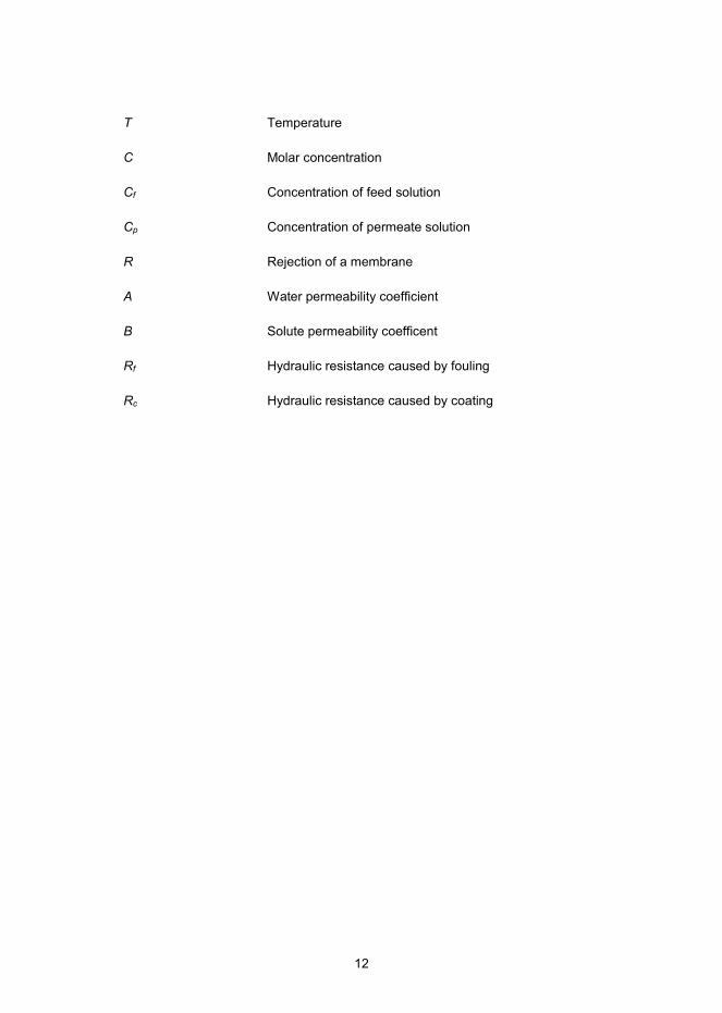
T Temperature
C Molar concentration
Cf Concentration of feed solution
Cp Concentration of permeate solution
R Rejection of a membrane
A Water permeability coefficient
B Solute permeability coefficent
Rf Hydraulic resistance caused by fouling
Rc Hydraulic resistance caused by coating
13
1. Introduction
Economic pressures and competition have created a need for superior perfor-mance and multifunctional properties of materials. The ever-increasing demand for new product properties makes it challenging to achieve the required features when using traditional materials. Therefore, new material combinations (i.e. hybrid or composite materials) are intended to meet these challenges, providing added value for the existing products or creating novel spinoffs.
The difference between hybrid and composite materials is narrow, and in some cases the terms overlap. Hybrid material can be defined as a combination of mate-rials, which are composed of at least two different materials, usually inorganic and organic [1]. Indeed, hybrid material is typically a blend, multilayer or nanostruc-tured material. Moreover, composite is a consolidation of materials, in which the matrix material is further enhanced using particles, fibres or coatings.
In recent years, significant progress has been made in the choice of materials and in the manufacturing routes for nanocomposites. Totally new properties can be obtained using only nanoscale fillers [2]. For example, carbon nanotubes and fibres have been studied for reinforcement in nanocomposites [3]. Among the nanocomposite research, the modification of bulk material has gained most atten-tion. Nevertheless, the fabrication of such materials in the form of thin films can also provide special features. For example, a thin-film composite (TFC) structure can be expected to tailor the permeability of polymeric films applied in various industrial applications, ranging from non-permeable packaging to semi-permeable membranes. TFCs usually have a three layer structure, containing a support, a core and a skin layer.
Permeation is described as diffusion of a permeate (e.g. liquid, gas, ions or par-ticles) from a high concentration to a low concentration [4]. Permeability is the measured material permeation property, describing the penetration of permeate through a solid interface [4]. Tailored permeability of a material usually indicates the creation of a barrier against a permeate [5]. These barrier layers can be semi- or non-permeable structures. The former is a mesoporous bulk material or coating layer, which rejects the desired gases, vapours, liquids, ions or particles, and is permeable for the targeted substance, while the latter is a nonporous bulk material or a coating layer, which rejects the targeted substances.

14
Food and pharmaceutical packaging is a typical example, where non-permeable features are desired. Food packaging is needed to protect the items of food from various exposures. New developments aim to improve the barrier properties or to create antimicrobial activity to prevent the microbiological spoilage of food [6]. Furthermore, recyclable and renewable materials are considered to increase the sustainability of packaging by replacing the existing metal or polymer coatings. Therefore, various new polymers, biopolymers, nanoparticles and coatings have been studied [6]. Another recent trend in packaging material development is leading towards high barrier performance with a minimal amount of material [6]. Therefore, there is a need for functional coatings on paper, paperboard and plastic laminates for special or enhanced properties in the field of paper converting.
A water treatment membrane is used in various filtration processes to provide purified water or other liquids. A membrane is a typical example of a semi-permeable structure [7]. The membranes used in reverse osmosis (RO) and nano-filtration (NF) have a nearly nonporous structure [8]. The commercial RO and NF membranes are based on either cellulose acetate (CA) or polyamide (PA) TFC. The latter is composed of polyethersulfone (PES) cast on non-woven as a core and a support layer, which is further coated with PA as a skin layer. The fouling of membranes, such as colloidal fouling (inorganic and organic) or biofouling, is a critical issue in pressure-driven membrane processes [9]. The routes for low-fouling membranes include new polymers or their combinations, and incorporation of nanoparticles, biocides or pore-forming agents [10]. In addition, various anti-fouling coating approaches have been presented in the literature [10]. The optimal surface properties have, however, remained undetermined. Further research is, therefore, needed to identify the connection between membrane surface properties and the accumulation of biofilm.
Figure 1 presents the materials and processes of this thesis. Firstly, the aim was to fabricate a TFC with tailored permeability. Secondly, the aim was to enhance the anti-fouling performance of a TFC-PA. Industrially applicable and novel coating methods were used so as to fabricate TFCs by using roll-to-roll or batch processes. Inorganic, inorganic-organic and organic surface chemistries were created using coating methods such as sol-gel (SG), atmospheric plasma deposition (APD), atomic-layer-deposition (ALD) and polyvinyl alcohol (PVA) based dispersion. These were deposited either as skin layers on a low-density polyethylene (LDPE) or a polylactic acid (PLA)-coated board or as a top-coating on a TFC-PA membrane.
The scientifically novel contribution of this thesis is as follows. The thesis con-tributes to the development of novel TFC structures using various coating meth-ods. The novel TFC structures provide new alternatives or improvements for the existing barrier materials in food packaging. In addition, the developed anti-fouling coatings tackle the critical challenge of membrane fouling and introduce new low-fouling TFC-PA membranes for water treatment.
The effects of coating chemistry and composition of the multilayer structure were studied in order to find optimal permeability. In particular, the difference between 2- and 3-dimensional oligomeric sol-gel coating layers was of interest. Non-polar polymers (e.g. LDPE) are known for their low-adhesion to coatings or

15
inks. Therefore, it was essential to study the effect of plasma-assisted deposition and pre-treatment on the adhesion between the coating layers and the substrate. The polymer surfaces (e.g. PLA) can be relatively rough and therefore challenges can be expected when applying a uniform and nano-sized coating layer. Conse-quently, the effect of a primer layer was also needed to study the deposition of an extremely thin ALD layer.
In membrane technologies for water treatment, the permeability is targeted to remain unmodified after applying a top-coating. For example, the permeability of a membrane may be reduced when an additional anti-fouling coating layer is used. In this thesis, organic and inorganic anti-fouling coatings were developed for TFC-PA membranes with bacterial anti-adhesion and antimicrobial performances. Firstly, the effect of the surface physiochemical properties on the attachment of bacteria was of interest. The correlation between surface polarity and bacteria repellence was demonstrated by using PVA and ALD coatings. In addition, for the first time the ALD method was studied as a surface modification of TFC-PA membranes. Secondly, the anti-fouling performance was further enhanced by the combination of a biocide effect with the desired surface properties. The PVA-based antimicrobial coatings were investigated in order to overcome an uncontrolled leaching of biocides.
Figure 1. The schematic presentation describes the materials and processes of the PhD thesis, which investigates various coating technologies in order to tailor the permeability and anti-fouling performance of thin-film composites.

16
2. Advanced surface modification of polymeric substrates
The surface modification of a polymeric material can occur as a result of a chemical or a physical reaction [11]. In addition, a coating layer may attach to a substrate by mechanical interlocking.
The chemical reaction can occur through grafting-to or grafting-from methods, when appropriate chemically reactive groups can be found on the surface. The linkage or coupling directly to the existing end groups of the surface is called the grafting-to method [12]. This does not cause changes in the bulk material. In some cases, surface activation is needed prior to the coating deposition. The grafting-from method involves a chemical reaction of the coating to the solid surface, after it has been physically activated [12]. In general, the surface activation involves controlled degradation of the surface, using high energy radiation, such as electron beam, plasma or ultraviolet (UV) radiation.
The chemical bonding of the coating on the substrate is not necessary in every case. A coating application is also possible through physical adsorption, where the coating is attached by electrostatic forces [11]. Layer-by-layer deposition (LBL) is a common method to produce an electrostatically adhered coating. In addition to chemical and physical bonding, the coating can be attached by mechanical inter-locking. In this case, the coating is attached on a rough or porous structure of the substrate [11]. Moreover, the attachment of the coating may be a combination of a chemical or physical reaction with mechanical interlocking.
2.1 Atmospheric plasma pre-treatment of polymers
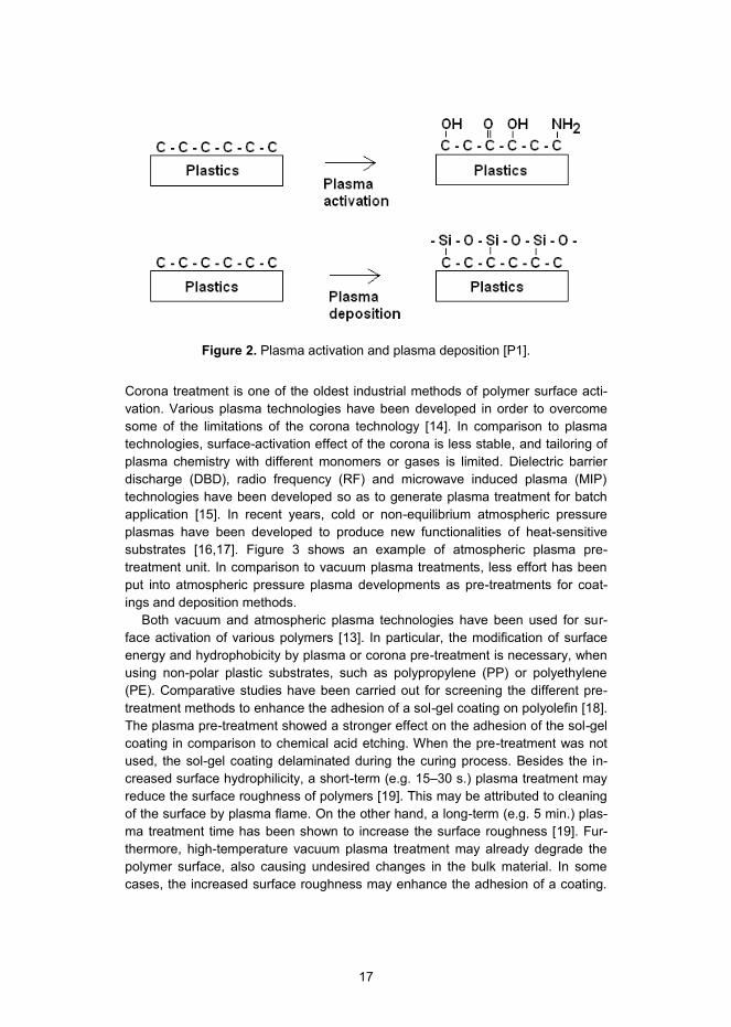
Corona and plasma treatments of polymers are known to enhance their wettability and adhesion to coatings, inks and adhesives [13]. Moreover, a hydrophilic sur-face tends to provide better adhesion than hydrophobic ones [11]. The surface energy can be tailored according to the need using different treatment gases or chemicals. Figure 2 presents schematically the difference of plasma-activation and plasma deposition.
17
Figure 2. Plasma activation and plasma deposition [P1].
Corona treatment is one of the oldest industrial methods of polymer surface acti-vation. Various plasma technologies have been developed in order to overcome some of the limitations of the corona technology [14]. In comparison to plasma technologies, surface-activation effect of the corona is less stable, and tailoring of plasma chemistry with different monomers or gases is limited. Dielectric barrier discharge (DBD), radio frequency (RF) and microwave induced plasma (MIP) technologies have been developed so as to generate plasma treatment for batch application [15]. In recent years, cold or non-equilibrium atmospheric pressure plasmas have been developed to produce new functionalities of heat-sensitive substrates [16,17]. Figure 3 shows an example of atmospheric plasma pre-treatment unit. In comparison to vacuum plasma treatments, less effort has been put into atmospheric pressure plasma developments as pre-treatments for coat-ings and deposition methods.
Both vacuum and atmospheric plasma technologies have been used for sur-face activation of various polymers [13]. In particular, the modification of surface energy and hydrophobicity by plasma or corona pre-treatment is necessary, when using non-polar plastic substrates, such as polypropylene (PP) or polyethylene (PE). Comparative studies have been carried out for screening the different pre-treatment methods to enhance the adhesion of a sol-gel coating on polyolefin [18]. The plasma pre-treatment showed a stronger effect on the adhesion of the sol-gel coating in comparison to chemical acid etching. When the pre-treatment was not used, the sol-gel coating delaminated during the curing process. Besides the in-creased surface hydrophilicity, a short-term (e.g. 15–30 s.) plasma treatment may reduce the surface roughness of polymers [19]. This may be attributed to cleaning of the surface by plasma flame. On the other hand, a long-term (e.g. 5 min.) plas-ma treatment time has been shown to increase the surface roughness [19]. Fur-thermore, high-temperature vacuum plasma treatment may already degrade the polymer surface, also causing undesired changes in the bulk material. In some cases, the increased surface roughness may enhance the adhesion of a coating.

18
However, the surface roughness should not exceed the thickness of the coating layer. Low-temperature atmospheric plasma treatment may overcome these chal-lenges. Moreover, atmospheric plasma has resulted in a strong increase in the surface energy, while the surface roughness was not affected [19]. Atmospheric plasma experiments have been shown to create durable hydrophilicity for im-proved adhesion between polymer surfaces and additional coating layers [20].
Figure 3. An example of atmospheric plasma pre-treatment unit.
2.2 Atmospheric plasma deposition of thin coatings on polymers
Recently, atmospheric plasma deposition (APD) of functional coatings on plastic films has gained increasing attention [16]. The main advantages of atmospheric plasma systems are the possibility of using different treatment gases and gas mixtures as well as deposition of chemicals [14]. In addition, the processing is more flexible and feasible, because there is no need to use a vacuum reactor or other low pressure systems.
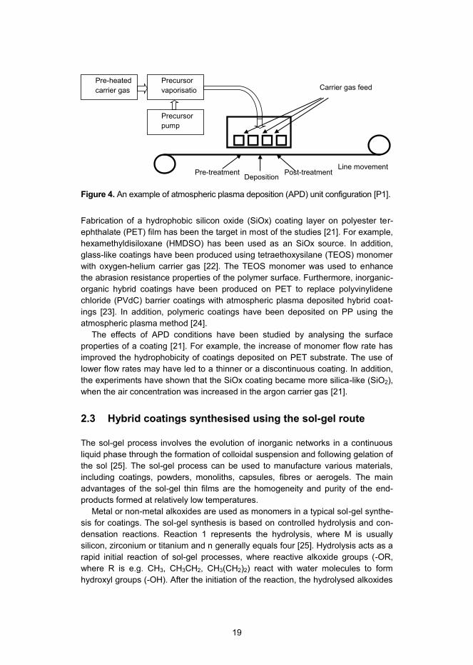
An example of a plasma deposition unit and its configuration is described in Figure 4. Plasma deposition or plasma enhanced chemical vapour deposition (PECVD) is typically based on dielectric barrier discharge (DBD) plasma [16]. The two general types of PECVD methods are direct (glow) and remote (afterglow). In the direct method, the monomer is fed together with the plasma gas to the dis-charge area, resulting in reaction of the monomer. In the remote method, the monomer is fed and activated in the downstream of the discharge and, thus, only the carrier gas is fed through the discharge. Deposition of various molecules or compounds is allowed. Furthermore, the substrate has a enough long distance from the discharge, enabling treatments of heat-sensitive materials, such as polymers.
19
Figure 4. An example of atmospheric plasma deposition (APD) unit configuration [P1].
Fabrication of a hydrophobic silicon oxide (SiOx) coating layer on polyester ter-ephthalate (PET) film has been the target in most of the studies [21]. For example, hexamethyldisiloxane (HMDSO) has been used as an SiOx source. In addition, glass-like coatings have been produced using tetraethoxysilane (TEOS) monomer with oxygen-helium carrier gas [22]. The TEOS monomer was used to enhance the abrasion resistance properties of the polymer surface. Furthermore, inorganic-organic hybrid coatings have been produced on PET to replace polyvinylidene chloride (PVdC) barrier coatings with atmospheric plasma deposited hybrid coat-ings [23]. In addition, polymeric coatings have been deposited on PP using the atmospheric plasma method [24].
The effects of APD conditions have been studied by analysing the surface properties of a coating [21]. For example, the increase of monomer flow rate has improved the hydrophobicity of coatings deposited on PET substrate. The use of lower flow rates may have led to a thinner or a discontinuous coating. In addition, the experiments have shown that the SiOx coating became more silica-like (SiO2), when the air concentration was increased in the argon carrier gas [21].
2.3 Hybrid coatings synthesised using the sol-gel route
The sol-gel process involves the evolution of inorganic networks in a continuous liquid phase through the formation of colloidal suspension and following gelation of the sol [25]. The sol-gel process can be used to manufacture various materials, including coatings, powders, monoliths, capsules, fibres or aerogels. The main advantages of the sol-gel thin films are the homogeneity and purity of the end-products formed at relatively low temperatures.
Metal or non-metal alkoxides are used as monomers in a typical sol-gel synthe-sis for coatings. The sol-gel synthesis is based on controlled hydrolysis and con-densation reactions. Reaction 1 represents the hydrolysis, where M is usually silicon, zirconium or titanium and n generally equals four [25]. Hydrolysis acts as a rapid initial reaction of sol-gel processes, where reactive alkoxide groups (-OR, where R is e.g. CH3, CH3CH2, CH3(CH2)2) react with water molecules to form hydroxyl groups (-OH). After the initiation of the reaction, the hydrolysed alkoxides
Line movement
Carrier gas feed Precursor
vaporisation
Precursor pump
Pre-heated carrier gas
Pre-treatment Deposition Post-treatment

20
easily react with each other, forming dimers through the condensation reaction. Water or alcohol is obtained as a by-product, depending on the reaction mecha-nism. The condensation reactions are described with reactions 2 and 3.
M(OR)n + H2O M(OH) (OR) n-1 + ROH (1)
M(OH)(OR)n-1 + M(OR)n (OR)n-1MOM(OR)n-1 + ROH (2)
2 M(OH)(OR)n-1 (OR)n-1MOM(OR)n-1 + H2O (3)
The alkoxide monomers have a different reactivity, which is related to the partial charge of the metal or the non-metal alkoxide [25]. The reactivity of the monomers in hydrolysis and condensation reactions can be accelerated or hindered by using catalysts or by increasing or decreasing the reaction temperature.
Sol-gel coatings can be applied on various surfaces to provide functional prop-erties. Easy-to-clean, self-cleaning as well as anti-fouling coatings have been developed by using sol-gel chemistry. The surface chemistry (e.g. polarity) and topography (smooth or rough) can be modified based on the performance re-quirements. Furthermore, active agents such as biocides can be incorporated to the sol-gel coating matrix.
Figure 5 presents schematically the basis of sol-gel processing of thin coatings. A variety of different types of thin films and coatings can be synthesised by using the sol-gel technology. In general, the sol-gel thin films can either be pure inorganic or inorganic-organic hybrid materials. Different wet chemical coating methods can be used depending on the targeted approach. Drying of the applied coating is an important step, where solvents and water are evaporated in order to avoid cracking in the final curing stage. Typically, the thickness of inorganic layers is from 20 nm to 200 nm. The film thickness of the inorganic sol-gel thin film as a one-layer sys-tem cannot be raised much more, due to possible cracking behaviour.
Figure 5. Schematic presentation of sol-gel processing of thin coatings.
From the late 1980s, there has been an increasing interest in preparing inorganic-organic hybrid coatings using sol-gel syntheses [26]. The basic idea is to introduce

21
organic components into the nanostructured glass-like (e.g. SiO2) or ceramic (e.g. ZrO2, Al2O3) network. Thus, the hybrid coating is not as fragile as the pure inor-ganic coatings. Therefore, the coating thickness can be increased from tens of nanometres up to tens of micrometres. The hybrid coatings are typically two or three dimensional (2D or 3D) oligomer structures [26]. For example, TEOS can be used to form the inorganic Si-O-Si backbone. TEOS bonds via hydrolysis and condensation reactions to organically modified alkoxysilanes, which can contain variety of different functional groups that can be used to provide hydrophilic, hy-drophobic or even antimicrobial behaviour. This route can be used to create a 2D oligomeric structure. The 3D oligomeric hybrid structure is synthesised quite simi-larly as the 2D structure. The main difference is the use of silane coupling agents, which are organically modified alkoxysilanes or polymeric monomers, containing reactive groups (e.g. amino, isocyanate, vinyl, acryl, mercapto, methacryl or epoxy). These are able to polymerise, when induced using initiators, catalysts, cross-linkers, heat or radiation (e.g. UV or plasma) [16]. The 3D oligomer structure may improve the mechanical properties, elasticity and plasticity of the end-product. In addition, the highly cross-linked hybrid structure may be favourable for creating enhanced barrier performance.
Recently, the sol-gel technology has evolved to the next level and a few at-temptions to produce sol-gel coatings in inline process have been presented [16,23,P2]. Furthermore, the development of inorganic-organic hybrid structures makes it a potential choice to apply the sol-gel coatings on flexible paper, board or plastic film surfaces. The possibility to include functional groups and tailor-made the surface chemistry makes the sol-gel technology even more desirable.
2.4 Atomic-layer-deposition of inorganic thin coatings on polymers
Atomic-layer-deposition (ALD) is a chemical vapour deposition (CVD) technique based on cyclic and self-terminating gas–solid reactions. ALD can be considered as an advanced version of CVD technology. ALD technology enables the manu-facturing of several different kinds of inorganic materials such as oxides, nitrides, sulphides and others with thickness down to the nanometre range [27]. Moreover, polymeric and inorganic-organic hybrid films have been manufactured by using ALD technology [28].
One of the most studied ALD processes is deposition of Al2O3 thin films, which are prepared using trimethylaluminium (TMA, Al(CH3)3) and water or ozone as monomers [28]. The self-terminating reaction of TMA with water is also considered to be an ideal example of ALD process. The TMA monomer is highly reactive as well as thermally stable. The Al(CH3)3-H2O process involves switches from methyl- to hydroxyl-terminated aluminium as presented by the side reactions in equations 4 and 5. Methane is obtained as a gaseous reaction product and it does not dimin-ish the growth-per-cycle (GPC) of the Al2O3 thin film. Furthermore, the overall reaction of Al(CH3)3-H2O process is presented in equation 6.

22
Al-OH + Al(CH3)3 (g) Al-O-Al(CH3)2 + CH4 (g) (4)
Al-CH3 + H2O (g) Al-OH + CH4 (g) (5)
2 Al(CH3)3 (g) + 3 H2O (g) Al2O3 (s) + 6 CH4 (g) (6)
Figure 6 presents the ALD device used in this thesis. In a typical Al2O3 ALD pro-cess, vaporized TMA and H2O monomers are fed as pulses one-by-one into a vacuum chamber. Between the monomer pulses, an inert gas purge (e.g. N2) is used so as to remove unreacted monomers and by-products. After the gas purge, the saturated surface layer of the TMA can react with H2O, which is again subject-ed to a gas purge in order to complete the first ALD cycle [27]. These cycles can be repeated according to the desired film thickness or coating functionality.
Recent advances in ALD technology have increased its potential to produce functional thin films on flexible and temperature-sensitive polymeric materials [29]. ALD has also been applied to coat various fibrous polymers [30,31,32,33]. Alt-hough the ALD process is mainly carried out in batches in its current state, the development of a slow-speed roll-to-roll ALD technology is underway [34].
Figure 6. An example of atomic-layer-deposition (ALD) device.

23
3. Non-permeable packaging films
3.1 Permeability
Permeates (e.g. liquid, gas, ions or particles) diffuse from high concentration to low concentration [4]. The phenomenon is called permeation. The penetration of a permeate through a solid interface is described by permeability. Permeability is the material permeation property [4]. The transfer of permeate molecules through a material is a process that includes sorption, desorption and migration [4]. In gen-eral, the permeate molecules attach onto a material surface by a sorption mecha-nism. Migration occurs, when the attached molecules diffuse through the material. Finally, diffused molecules detach to the environment by desorption on the other side of the material.
Diffusion, solubility and permeability are the main parameters used to describe the mass transfer for a material [4]. The mass transfer of molecules can be de-scribed by the permeability coefficient (P) of the material [4]. The permeability coefficient, P, can be calculated using a solubility coefficient (S, solubility) and a diffusion coefficient (D, diffusivity). The permeability coefficient, P, is the volume of vapour (q) passing through a unit area of the polymer in a time unit, with a pres-sure difference unit across the polymer:
( ) ( )
( ) ( ) ( ) (7)
where, S is a thermodynamic term describing the volume of vapour per unit vol-ume of polymer per unit pressure, D is a kinetic term indicating the velocity of the molecule in the specific material. Respectively, q is the quantity of the permeant transferred by a unit of area (A) in a specific time (t), l is the thickness of the material, and Δp is the partial pressure difference.
The barrier performance of packaging material can be determined using various barrier measurements [35]. In general, the molecules diffusing into and through the packaging material are detected. For example, the measurement of gas and water vapour transmission is of interest due to their effect on the shelf-life of the packaged product. The oxygen transmission rate (OTR) is the quantity of oxygen (O2) molecules passing through an area in a certain time period under specified conditions of temperature, humidity and pressure [35]. The OTR measurement is
24
based on the O2 flux diffusing through the sample, which is detected using an electrochemical (non-coulometric) or a coulometric oxygen sensor. In the literature various units have been used to report permeability of gases [35]. The most commonly used unit for permeability of gases in barrier polymers is (cm3 mil) / (m2 day atm). Respectively, the water vapour transmission rate (WVTR) determines the amount of water vapour transmitted through an area in a certain time under specified con-ditions of temperature and humidity [36]. There are many standard procedures for measuring WVTR using gravimetric methods [37,38]. The most commonly used unit for permeability of water vapour in barrier polymers is (g mil) / (m2 day). OTR and WVTR values are reported in the literature as normalised to a layer thickness of 1 mil (1 mil = 25.4 µm).
3.2 Traditional packaging materials
Microbiological contamination is one of the major causes of food losses in the world [39]. Food packaging has been part of the food supply chain for decades. Among the traditional preservation systems, packaging technologies have an important role in securing food safety [40]. Furthermore, barrier films are needed in pharmaceutical packaging applications.
Packaging has to protect the substance from various environmental exposures, including oxygen, moisture, light, microbes and dust. Moreover, packaging material has certain requirements in terms of its usability (e.g. fresh outlook or decorative), technical aspects (e.g. sealability, easy opening, applicability for food contact, recyclability or refilling) and reasonable price [39].
Paper and paperboard (i.e. board) are so-called traditional packaging materials. They have several advantages, which make their use as food packaging extremely favourable. Paper and board meet the needs, because they have the required usability and technical properties, which enable their cost-effective use in a wide range of packaging structures. Furthermore, they can be coated, laminated or impregnated to improve their barrier properties and to extend their functional per-formance, such as heat sealability, heat resistance, barrier, grease resistance or product release. For example, board can be extrusion-coated using polymeric coatings made of polyethylene (PE).
Other traditional polymeric packaging materials include polypropylene (PP), polyamide (PA), polyethylene terephthalate (PET) and ethylene vinyl alcohol (EVOH) [16]. Furthermore, packaging performance can be further enhanced using surface treatments such as, polyvinylidene chloride (PVdC), wax, silicone or fluo-rocarbon based coating. Coatings can be applied by flexo, soft bar, foam, curtain and spray coating methods, including optional pre-treatments by plasma or corona and post-treatments/curing by cold or hot air drying, IR-drying or UV-curing.
Recently, bio-based and renewable coating materials have been introduced as a sustainable alternative to the petroleum-based polymeric materials [41]. For example, polylactic acid (PLA) has been applied to some extent in commercial

25
products. In addition, other bio-based materials, such as starch, xylan, chitosan and cellulose, have been investigated [41].
3.3 Developments of barrier films for packaging application
The polymers may have a variety of oxygen (O2) and water vapour (WV) barrier properties, which are affected by their chemical structure, crystallinity and orienta-tion [5]. Concerning the O2 permeability, the presence of polar groups in polymer chains often increases the chain rigidity and decreases the specific free volume. This can further increase its packing density and therefore, increase crystallinity in the polymer. As a result, the permeability of gaseous molecules is reduced through the polymer [5]. For example, a PLA contains more polar groups than an LDPE, and lower O2 permeability has been measured for PLA in comparison to LDPE. Respectively, PET and PA have lower O2 permeability in comparison to PP [42]. On the other hand, the polymer chain flexibility affects on the gas permeabil-ity. The non-polar methyl (-CH3) attached PP structure decreases the mobility of chains and decreases the gas permeability. Thus, PP has somewhat lower per-meability compared LDPE [5]. Concerning the WV permeability, the hydrophobicity of a polymer has an effect [5]. The non-polar structure shows repellence of polar water molecules. This partly explains the lower water vapour permeability of PP and PE in comparison to the other substances.
The stretching of amorphous and semicrystalline polymer films can improve their barrier properties. For instance, biaxial orientation (BO) of PET, PP and PA reduces both the O2 and WV permeability [43]. Furthermore, lamination and extru-sion coating are two additional industrial processes for producing multilayer barrier structures [41]. Several polymeric layers can be coated to form a high barrier material. For example, EVOH is typically extrusion-coated as one layer in the 3- or 5-layer system. Use of EVOH has led to a slight improvement in the barrier prop-erties [41]. The drawback of multilayer lamination is the increase in the coating thickness and, therefore, the increase of net weight of the packaging.
Active packaging materials have been widely studied and patented in recent years [40]. Active packaging materials include various types of functional systems, for example, oxygen, carbon dioxide and ethylene scavengers, carbon dioxide and ethylene emitters, moisture scavengers, ethanol emitters and absorbing systems as well as antimicrobial packaging materials [2]. Currently, oxygen and moisture scavengers are commercially the most significant, but other techniques have been predicted to play an important role in the near future.
Another recent trend in packaging materials is the change towards new func-tionalities using nanosized materials, such as nanoclays [2]. In addition, new sur-face treatments and coating technologies have been introduced to traditional packaging materials. The novel thin coating technologies may provide thinner barrier films. The replacement of conventional coating materials such as polyole-fins, EVOH, fluorocarbons and silicones, typically several microns thick, by na-noscale coatings has the evident benefits of both a reduction of consumed materi-

26
als and negative effects on recyclability. Furthermore, these new coating methods may replace the existing metallisation treatments in the future.
Recently, sol-gel hybrid coating and ALD technologies have shown promising barrier performance enhancement, when deposited on polymeric film or polymer (e.g. PLA or LDPE) coated board [44,45,P2,P3]. Among the ALD-coated PLA-board specimens, Al2O3 ALD coating showed better barrier performance than SiO2 [45]. Concerning the LDPE-board, the studies revealed that ALD-coating did not show as good barrier performance as shown for PLA-board [45]. This can be explained by the difference between the reactivity of the PLA and LDPE surfaces. Therefore, corona or plasma pre-treatment or primer layers could be used to im-prove the film growth or adhesion.
Some of the commercially available approaches include deposition of silicon oxide (SiOx) or aluminium oxide (AlOx)-based inorganic coatings on a polymer film for barrier property improvements [46]. The SiOx coating has been shown to reduce O2 and WV permeability of PET [47]. Furthermore, the oxygen and water vapour barrier of a BOPP film can be enhanced by deposition of nanometre thick inorganic AlOx layer [46]. However, the inorganic coating layers may be fragile and delaminate from the flexible polymer surface.
To overcome the delamination issue, thin-film composite (TFC) concepts have been developed, where thin organic and inorganic coating layers are separately deposited on polymers. The TFC concept for enhanced O2 barrier properties has already been presented in the late 1990s by Haas et al [48]. They deposited hy-brid sol-gel on a PP film, which was followed by the deposition of a SiOx layer. In addition, enhancement of barrier properties has been obtained with TFC structure of an AlOx and a few micrometre thick acrylate coating. Recently, a combination of sol-gel hybrid coating and ALD technologies has also shown promising barrier performance enhancement, when deposited on polymeric films or polymer coated boards [P3].

27
4. Semi-permeable thin-film composite membranes
4.1 Reverse osmosis (RO) membranes
Membrane filtration technology is used in various industries to provide purified water from sources including, mining, biorefinery, brackish, processing, or sea-water [7]. Moreover, the membrane filtration technology is utilised in microfiltration (MF), ultrafiltration (UF), nanofiltration (NF) and reverse osmosis (RO) [8]. These methods have been applied in water and wastewater treatment, desalination and water re-use since the late 1960s.
Reverse osmosis (RO) membranes are nonporous systems which retain parti-cles and low molecular weight species such as salt ions, micropollutants, pesti-cides and pharmaceuticals [8]. The commercial RO membrane materials are ei-ther cellulose acetate (CA) or thin-film composite (TFC) membrane, which consists of polyamide (PA) as a selective layer and polyethersulfone (PES) cast on non-woven as a support layer [8]. The traditional CA membranes were developed in the late 1950s and commercialized in the early 1960s. CA has formerly been widely used, but nowadays TFC-PA membranes are more common. The TFC-PA mem-branes offer several advantages over the CA membranes, such as improved re-tention, increased productivity at lower operating pressures, great structural stability, and the ability to produce two to three times more purified water per unit area than CA membranes [49].
Both of the TFC-PA and CA membranes have one common challenge restricting their usage in industrial processes: fouling. Membrane fouling has an unwanted effect on membrane separation efficiency as well as on energy consumption [9]. Membrane permeability declines, resulting in unstable water flux behaviour, and therefore feed pressure should be increased in order to stabilize the process [50].
4.2 Permeability of reverse osmosis (RO) membranes
Permeability of a membrane is important for applications in water and wastewater treatment. In general, there is a strong trade-off between water permeability and

28
salt rejection. The more water permeable membrane tends to have lower salt rejection and higher solute permeability [8].
An adequate water flux is essential because of its relationship to the membrane productivity and process economics. Water flux is defined as a mass (or a volume) passing through a membrane unit within a given duration of time [8]. The pure water flux Jv is typically defined as:
(8)
where Qp is the volumetric flow rate that permeates through the defined mem-brane area Am. In the literature the typical unit for water flux is L/m2h.
The effect of the applied pressure (P) and the osmotic pressure (π) of the solution on the permeate flux should be taken into account in the pressure-driven membrane systems [8]. Therefore, Darcy’s law can be commonly determined according to the following equation:
( )
(9)
where Rm is the hydraulic resistance of the membrane and η is the viscosity of the permeating water. Rm can be determined for a membrane according to its water permeability (A):
(10)
The applied pressure P, i.e. the trans-membrane pressure (TMP), is the differ-ence between the applied pressure on the feed water side and the pressure of permeate water [8]. The osmotic pressure, π, of the solutions can be determined by the van’t Hoff equation:
∑ (11)
where Rg is the universal gas constant (Rg = 8.31 J/mol K), T is the absolute tem-perature given in Kelvin degrees, and C is the molar concentration of dissolved substances. In addition to the water flux, solute retention is one of the most im-portant performance parameters for a membrane process. The retention ability of a membrane in water applications is expressed by the membrane rejection. Mem-brane rejection (R) can be determined by:
(12)

29
where Cf and Cp are the concentrations (via conductivity measurements) of the feed and permeate solutions, respectively. Based on the literature, the solution-diffusion model is the most widely used transport model for RO membranes [8]. It is assumed that both solvent and solute absorbs into the rejection layer and dif-fuses through the nonporous layer [8]. Therefore, the water flux, Jv, through an RO membrane corresponds to the applied pressure (P-π). Respectively, solute flux, Js, through an RO membrane corresponds to the concentration difference (C) across the membrane.
( ) (13)
where A is the effective water permeability of an RO membrane.
( ) (14)
where B is the effective solute permeability of an RO membrane. A more funda-mental property describing the real salt permeability of an RO membrane is the solute permeability coefficient (B) [8]. The solute permeability coefficient can be determined from the water flux and rejection test results via:
( )(
-1) (15)
4.3 Fouling of reverse osmosis (RO) membranes
Membrane fouling occurs when particles and solutes accumulate on the mass transfer boundary layer of the membrane and they begin to impede the solvent flow through the membrane [9]. Fundamentally, the fouling layer increases the hydraulic resistance on the membrane surface and, therefore, Darcy’s law for water flux (Jv) can be determined according to [8]:
( )
( ) (16)
where, Rf is the hydraulic resistance caused by fouling. After the initiation of the fouling macromolecules, proteins, gels or particles will continue adsorbing on the membrane surface [9]. The types of membrane fouling are classified into colloidal (inorganic and organic) and biological fouling (i.e. biofouling). Inorganic fouling (i.e. scaling) is occurred by deposition of major ions on membrane surface including calcium, magnesium, barium, bicarbonate, sulphate and inorganic salts. This causes pore-blocking and reduction of the water flux. The scaling is mainly avoid-ed chemically by using antiscalants and pH control to pre-treat the feed solution before the separation process. Organic fouling typically involves attachment of proteins and humic acid on the membrane surfaces. Several researchers have studied the effects of the surface properties on the organic fouling tendency of the commercial RO membranes [51,52,53].

30
Biofouling is generally initiated by adhesion and accumulation of the microor-ganisms, which is followed by primary colonization and logarithmical growth [54]. In addition, a number of the microorganisms, such as bacteria, can be detected within the network of extracellular polymer substances (EPS). It is difficult to completely eliminate biofouling and, therefore, it is problematic for all membranes, especially in RO and NF processes [54]. The biofouling tendency of commercial membranes has been studied by several research groups [55,56,57]. Moreover, a few studies have concentrated on the interaction between bacteria and the surface properties of a variety membranes [58,59,60,61]. These previous studies have revealed that bacterial anti-adhesive behaviour varies between the different membranes.
The membrane surface properties have been shown to play an important role in affecting biofilm formation [62]. Studies have shown that membrane surface prop-erties such as hydrophobicity, surface roughness and surface charge have an effect on the reduction in fouling [63]. Most of the commercial RO membranes are hydrophilic rather than hydrophobic. For example, it has been shown that TFC-PA and CA membranes have water contact angle values between 20–60º [62]. The TFC-PA membranes for RO processes are typically aromatic or semi-aromatic. Fully aromatic PA membranes are formed by 1,3-benzenediamine (m-phenylenediamine) and trimesoyl chloride (1,3,5-benzenetricarbonyl chloride) [64]. Respectively, the semi-aromatic poly(piperazinamide) membranes are formed by piperazine and trimesoyl chloride [64]. However, it is difficult to conclude whether the RO mem-brane has a hydrophilic nature based on chemical structure. Some of the com-mercial TFC-PA membranes are coated with an additional thin polyvinyl alcohol (PVA) layer in order to introduce a hydrophilic and smooth surface [64]. The water contact angle value of a fully aromatic PA membrane is reduced significantly by applying the PVA coating. On the other hand, the PVA coating layer has only a minor effect on the semi-aromatic membranes [64].
4.4 Development of low-fouling thin-film composite membranes
The development of new anti-fouling RO membranes has gained increasing atten-tion [10]. In many cases, an anti-fouling membrane is achieved by combining the surface physiochemical properties, such as increased hydrophilicity, lowered sur-face roughness and neutralised surface charge [10]. These physiochemical anti-fouling properties are commonly referred to as anti-adhesion surfaces. In addition, antimicrobial surfaces have been presented as an active anti-fouling approach. Several different ways have been used to modify a membrane material itself or its surface by an additional coating layer.
The membrane material has usually been modified using polymer blends or composites, which consist of another polymer or some additives including titanium dioxide (TiO2) or silica (SiO2) nanoparticles and biocides (e.g. silver, copper, zinc or quaternary ammonium) [65]. In several approaches, improved water flux through a membrane is achieved by incorporating pore-forming agents, such as
31
silica, zeolites, carbon nanotubes and aquaporin protein into the skin or mem-brane layer [66].
Various different surface treatments have been developed for RO membranes. These include: 1) surface grafting of antimicrobial groups, 2) contact active am-phiphilic, microbe-repelling or anti-adhesive polymers, 3) functional coating meth-ods (LBL, casting, dipping, soaking or spraying) or 4) reactive coating methods (CVD, sputtering, UV and plasma immobilization) [10]. An ideal fouling-resistant coating would be an ultrathin, highly water-permeable surface layer that does not significantly increase the resistance to water flux [11]. The additional coating layer may indeed increase the hydraulic resistance of the membrane surface and the flux can thus be determined using Darcy’s law:
( )
( ) (17)
where, Rc is the hydraulic resistance caused by the coating. For example, the water flux through the membrane may be reduced, if the top-coating layer is much more hydrophobic, denser or thicker in comparison to the PA rejection layer.
The surface modification occurs mostly on the outermost surface of a mem-brane. For example, the CA membrane surface bears several hydroxyl groups for the chemical bonding. Furthermore, low concentrations of the amino or carboxylic groups can be found in TFC-PA membranes. Most of the polymeric membranes are, however, chemically rather stable and thus the controlled activation of the membrane is complicated or even impossible without changing the polymer bulk material morphology. Therefore, grafting-from approaches have been used in order to increase the reactive area of the surface and, furthermore, to increase the coverage of applied surface modification [11]. For example, the silylation of sur-faces by using functional alkoxy- or chlorosilanes is one of the well-known meth-ods for introducing reactive groups (amino, isocyanate, aldehyde, epoxide or car-boxyl) onto a solid surface. The silylation layer is typically only molecular with a thickness of about 1 nm. In addition, physical activations (ion, plasma or UV) have been used to improve the adsorption of the coupling agents on the membrane surface.
Concerning the development in low-fouling TFC-PA membranes, the research groups have applied their surface treatments to either commercial or experimental TFC-PA membrane. The different treatments can be divided into passive (e.g. hydrophilication and lowering surface roughness) and active (e.g. antimicrobial) fouling prevention approaches as well as methods focusing on flux improvement [10]. Most of the studies have focused on the deposition of hydrophilic polymer brushes, which have either anionic or non-ionic behaviour [67,68,69]. For example, polyethyleneglycol (PEG), methacrylate acid (MA), polyethyleneglycolmethacrylate (PEGMA) and copolymers of N-isopropylacrylamide and acrylic acid (P(NIPAm-co-AAc)) have been applied on TFC RO membranes for repellence of bacteria and protein [70,71,72]. Some of the approaches have focused on plasma-assisted grafting of molecular layers. Also, plasma deposition has been used to fabricate

32
the coatings [73,74]. Silane coupling agents have recently been used to create hydrophilic and hydrophobic surfaces on TFC-PA membrane. This approach showed a flux decline of the TFC-PA membrane, because of increased hydropho-bicity by the silane coupling agents. On the other hand, the use of silane coupling agents significantly increased the salt rejection of the TFC-PA membrane [75,76,77]. A few research groups have investigated atomic-layer-deposition (ALD) technology as surface modification of porous polymeric and ceramic mem-branes, which are used in microfiltration and ultrafiltration [78,79,80,81,82]. These studies suggested that ALD processing parameters, such as temperature and the number of ALD cycles, have a clear impact on membrane performance. For ex-ample, they have shown an effect on the pore size of membranes, which has affected solute permeability and rejection properties [80,81]. Furthermore, hydro-philic and low surface roughness polymeric membranes have been obtained by using TMA based ALD technology [79]. This could increase the potentiality of the ALD method to create low-fouling membrane surfaces. However, hydrophilicity and low surface roughness have typically been obtained using a relatively thick ALD coating, such as 300–500 ALD cycles [78,80]. In addition, change in the ALD processing temperature has an effect on the reactivity of TMA [31]. For example, the most hydrophilic membrane surface has been obtained at 150ºC [78].
33
5. Aims of the study
The aims of this research were to fabricate and modify thin-film composite struc-tures with tailored permeability and anti-fouling performance. In particular, the interest was in studying the effects of pre-treatment, coating chemistry and multi-layer coating structure on the permeability of a thin-film composite (TFC). In addition, the thesis aimed to gain further understanding of the anti-fouling phenomena of coated TFC membranes.
This study was limited to industrially applicable coating methods by studying both roll-to-roll and batch processes. Inorganic, organic and inorganic-organic surface chemistries were created using coatings based on sol-gel (SG), atmos-pheric plasma deposition (APD), polyvinyl alcohol (PVA) and atomic-layer-deposition (ALD). These were deposited either as a skin layer on low-density polyethylene (LDPE) or polylactic acid (PLA)-coated board, or as a top-coating on a polyamide (PA)-based TFC membrane. Because of the variety of substrate materials, the coating application processes were investigated together with the surface properties obtained by a coating. The end-applications were targeted for food packaging [P1–P3] and for water treatment membranes [P4–P6]. The re-search questions of this study were as follows:
Can TFC structure be fabricated with tailored permeability?
o Does SiOx coating form on LDPE-board using atmospheric plasma deposition? [P1]
o Does atmospheric plasma pre-treatment enhance the wettability and adhesion of sol-gel coatings deposited on LDPE-board? [P2]
o Does 2-dimensional or 3-dimensional sol-gel network have different ef-fect on the gas permeability of LDPE-board? [P2]
o Do TFC structure-based sol-gel and ALD coatings reduce the gas and water vapour permeability of PLA-board? [P3]
Does top-coating enhance the anti-fouling performance of TFC membrane?
o Does the increase in surface polarity reduce the attachment of model bacteria? [P4–P6]
34
o Can an organic or inorganic coating layer create an anti-fouling effect on a TFC membrane without sacrificing the permeability of the sub-strate? [P5–P6]
o Can the anti-fouling effect be enhanced by combining hydrophilicity and low surface roughness with antimicrobial additives? [P5]
o What is the effect of ALD processing temperature and number of ALD cycles (i.e. film thickness) on hydrophilicity, surface roughness and permeability of TFC membrane? [P6]
35
6. Experimental procedures
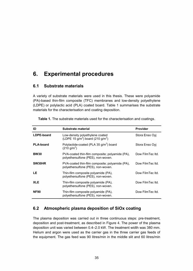
6.1 Substrate materials
A variety of substrate materials were used in this thesis. These were polyamide (PA)-based thin-film composite (TFC) membranes and low-density polyethylene (LDPE) or polylactic acid (PLA) coated board. Table 1 summarises the substrate materials for the characterisation and coating deposition.
Table 1. The substrate materials used for the characterisation and coatings.
ID Substrate material Provider
LDPE-board Low-density polyethylene coated (LDPE 15 g/m2) board (210 g/m2)
Stora Enso Oyj
PLA-board Polylactide-coated (PLA 35 g/m2) board (210 g/m2)
Stora Enso Oyj
BW30 PVA-coated thin-film composite; polyamide (PA), polyethersulfone (PES), non-woven.
Dow FilmTec ltd.
SW30HR PVA-coated thin-film composite; polyamide (PA), polyethersulfone (PES), non-woven.
Dow FilmTec ltd.
LE Thin-film composite polyamide (PA), polyethersulfone (PES), non-woven.
Dow FilmTec ltd.
XLE Thin-film composite polyamide (PA), polyethersulfone (PES), non-woven.
Dow FilmTec ltd.
NF90 Thin-film composite polyamide (PA), polyethersulfone (PES), non-woven.
Dow FilmTec ltd.
6.2 Atmospheric plasma deposition of SiOx coating
The plasma deposition was carried out in three continuous steps: pre-treatment, deposition and post-treatment, as described in Figure 4. The power of the plasma deposition unit was varied between 0.4–2.0 kW. The treatment width was 380 mm. Helium and argon were used as the carrier gas in the three carrier gas feeds of the equipment. The gas feed was 90 litres/min in the middle slit and 60 litres/min
36
in both side slits. In a typical plasma deposition experiment, the precursors were vaporized in the pre-heated carrier gas prior to the deposition. The SiOx source was hexamethyldisiloxane (HMDSO) precursor and it was used as such. The precursor (HMDSO) feed was 980 g/h. With the target of developing an industrially applicable plasma deposition method, the line speeds of 2, 5, 50, 100 and 200 m/min were used.
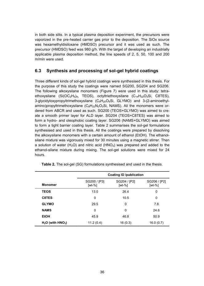
6.3 Synthesis and processing of sol-gel hybrid coatings
Three different kinds of sol-gel hybrid coatings were synthesised in this thesis. For the purpose of this study the coatings were named SG200, SG204 and SG206. The following alkoxysilane monomers (Figure 7) were used in this study: tetra-ethoxysilane (Si(OC2H5)4, TEOS), octyltriethoxysilane (C14H32O3Si, C8TES), 3-glycidyloxypropyltrimethoxysilane (C9H20O5Si, GLYMO) and 3-(2-aminoethyl-amino)propyltrimethoxysilane (C8H22N2O3Si, NAMS). All the monomers were or-dered from ABCR and used as such. SG200 (TEOS+GLYMO) was aimed to cre-ate a smooth primer layer for ALD layer. SG204 (TEOS+C8TES) was aimed to form a hydro- and oleophobic coating layer. SG206 (NAMS+GLYMO) was aimed to form a tight barrier coating layer. Table 2 summarises the sol-gel formulations synthesised and used in this thesis. All the coatings were prepared by dissolving the alkoxysilane monomers with a certain amount of ethanol (EtOH). The ethanol-silane mixture was vigorously mixed for 30 minutes using a magnetic stirrer. Then a solution of water (H2O) and nitric acid (HNO3) was prepared and added to the ethanol-silane mixture during mixing. The sol-gel solutions were mixed for 24 hours.
Table 2. The sol-gel (SG) formulations synthesised and used in the thesis.
Monomer
Coating ID /publication
SG200 / [P3] [wt-%]
SG204 / [P2] [wt-%]
SG206 / [P2] [wt-%]
TEOS 13.0 26.4 0
C8TES 0 10.5 0
GLYMO 29.5 0 7.8
NAMS 0 0 24.6
EtOH 45.9 46.8 50.9
H2O (with HNO3) 11.2 (0.4) 16 (0.3) 16.0 (0.7)

37
TEOS [83]
GLYMO [84]
C8TES [85]
NAMS [86]
Figure 7. The chemical structures of the monomers used in the sol-gel hybrid coatings.
6.3.1 Sol-gel-coated LDPE-board
The sol-gel coatings, named SG204 and SG206 for this study, were spray-coated onto LDPE-board. The atmospheric plasma equipment with argon or helium treatment gases was used to activate the LDPE surface prior to deposition of the sol-gel coatings. The following parameters were used for the plasma-activation: treatment power 2 kW, treatment width 370 mm, air gap 1–2 mm and speed 100 m/min. The sol-gel hybrid coatings were spray-coated onto the plasma-activated LDPE surface using the line speed of 60 m/min. The coatings were thermally cured in a pilot coating line by using infrared and suspended heaters.
6.3.2 Sol-gel-coated PLA-board
The sol-gel coating, named SG200 for this study, was sprayed onto corona-treated A4-size PLA-board substrates and heat-treated at 120°C for 10 mins. Traditional corona treatment unit (ET1 from Vetaphone, Denmark) with a treat-ment time of 60 s was used to ensure wetting and adhesion properties between the coating and the PLA-board substrate.

38
6.4 ALD processing of Al2O3 coatings
6.4.1 ALD deposition on sol-gel-coated PLA-board
The ALD-Al2O3 depositions were carried out on the sol-gel coated PLA-board at 80°C using a Picosun SUNALE™ reactor (Picosun, Espoo, Finland). Trimethyl-aluminum (TMA, electronic grade purity, SAFC Hitech) and H2O were used as precursors. The nominal thicknesses of the coating were estimated based on a growth rate of 0.1 nm/cycle [44,45]. In comparison to a silicon wafer, the ALD coatings have shown a minor variation in the actual film thickness, because of the difference in surface chemistry and roughness of different polymers.
6.4.2 ALD deposition on TFC-PA
The ALD-Al2O3 depositions were carried out in a Picosun SUNALE™ reactor on substrates that were 10×10 cm2 in size. TMA and H2O were used as precursors. Two different processing temperatures (70ºC and 100ºC) and three different ALD cycles (10, 50 and 100) were used to deposit the ALD coatings on the commercial LE-400 TFC-PA membranes. The coated membranes were named according to the coating cycles and temperature (e.g. c10_t70 denotes a membrane with 10 coating cycles at 70ºC). The precursor pulsing sequence was: 0.1 s TMA pulse, 10 s N2 purge, 0.1 s H2O, 10 s N2 purge and the number of ALD cycles was ad-justed according to the targeted Al2O3 coating thickness (0.1 nm/cycle).
6.5 Preparation and processing of PVA and PVA-PHMG coatings
The following chemicals were used for the membrane surface modification. PVA (molar weight 9000-10,000 g/mol, 80 % hydrolysed) polyvinyl alcohol was pur-chased from Sigma-Aldrich. PHMG, polyhexa-methylene guanidine hydrochloride (C7N3H15HCl, Mw 8000-10,000 g/mol) was provided by Soft Protector Oy (Fin-land). The chemical structures are presented in Figure 8.
Polyvinyl alcohol (PVA)
Polyhexamethylene guanidine hydrochloride (PHMG)
Figure 8. Chemical structure of polyvinyl alcohol (PVA) and polyhexamethylene guanidine hydrochloride (PHMG).

39
The preparation of the PVA coatings was carried out by mixing 2 wt-% of PVA into milliQ water at 60ºC. After complete mixing, the solution was cooled down to room temperature. The PVA-PHMG solutions were similarly prepared as described above, by adding PHMG to the PVA solution after the cooling step. PVA-PHMG solutions were prepared in ratios 95:5 and 99:1 (PVA:PHMG) with a total polymer content of 2 wt-%. The pure PHMG solution (2 wt-%) was prepared by mixing PHMG with milliQ water to reach the targeted concentration. PVA, PVA-PHMG and PHMG solutions were applied on the commercial LE-400 TFC-PA membrane coupons using the dispersion coating method with a K Control Coater K202 device (RK Print-Coat Instruments Ltd., United Kingdom). The device was equipped with a glass bed, and K202 coating bar No. 0 was used to cast the wet films with a thickness of 4 µm. The coatings applied were heat-treated at 110ºC for 2 minutes in order to evaporate the water and to increase the coating stability using thermal cross-linking [87].
6.6 Surface characterisation
A Perkin Elmer spectrum BX II FTIR (Fourier transform IR) system (USA) was equipped with vertical-ATR (Attenuated total reflectance) and KRS-5 (Thallium Bromoiodide) crystal [P3–P6]. ATR-FTIR measurements were carried out in order to analyse the surface chemistry. In a typical analysis 50 scans were collected from 500 to 4000 cm-1 at 4 cm-1 resolution. A background spectrum of pure KRS-5 was collected before running the samples.
The microscopic imaging was conducted using a scanning electron microscope (SEM) JEOL JSM-6360 LV equipment (USA) with 11 kV on high vacuum mode [P3–P6]. All SEM samples were sputter-coated with gold before imaging.
The surface topographies were characterised using non-contact mode atomic force microscopy (NC-AFM) [P1–P6]. The NC-AFM analysis was performed using Park Systems XE-100 AFM equipment (Suwon, South-Korea), with cantilever 905M-ACTA (AppNano Inc., USA). Typically, the scan rate was 0.4–0.6 Hz, and the measured area was 5x5 µm2. Six replicate measurements were taken in order to determine the roughness values, average roughness Ra or root-mean-square roughness value RRMS.
The contact angle measurements were taken using an Optical Tensiometer Theta T200 device (Biolin Scientific, Sweden) [P3–P6]. The measurements were taken in a controlled atmosphere (RH 50%, temperature 23ºC) and the results are given as an average of five parallel measurements. The water contact angle val-ues are presented at the time point of 30 s from the moment the drop contacts the surface. The surface energy values were obtained by measuring the contact angle of three different probe liquids, namely water (H2O, γ = 72.80 mN/m), di-iodo-methane (CH2I2, γ = 50.80 mN/m) and formamide (CH3NO, γ = 58.20 mN/m). The total surface energy values, as a summary of polar and dispersive surface energies, were determined from the measured contact angle data using Fowkes’ theory [88].

40
6.7 Anti-fouling performance
Bacterial anti-adhesion
Biofilm formation was demonstrated by analysing the attachment of Pseudomonas aeruginosa (P. aeruginosa) on uncoated and coated membranes [P3–P6]. P. aeruginosa is Gram-negative, aerobic, rod-shaped bacterium, which is widely used as a model microbe for biofilm formation studies [55,58,89]. Therefore, P. aeruginosa was selected as model bacterium in this study so as to provide comparable data related to the attachment of bacteria.
A bacteria attachment test was carried out by submerging the membranes (Ø 4.7 cm) in a bacterial suspension consisted of standard seawater ASTM D1141-98 (2008) [90]. The suspension was inoculated overnight with a culture of P. aeru-ginosa (VTT E-96726) cultivated in 37°C Trypticase soy agar (TSA) broth solution, harvested by centrifugation (3000 rpm, 10 mins) and washed with phosphate-buffered saline (PBS) solution (10 mM). The cell density was approximately 1×10⁸ CFU mL-1 determined by plate count on a TSA (37°C, 1 day). The 1 day exposure of membranes was conducted in a rotary shaker (75 rpm) at room temperature. The number of adhered cells on the membranes was determined after swabbing by plate count on TSA (37°C, 1 day), and it was intended to describe the anti-adhesion performance. Results are presented as colony-forming units per mem-brane area (CFU cm-2). Three replicate membrane samples were examined for each membrane type.
Antimicrobial activity
The antimicrobial performance of uncoated and coated membranes was analysed using the colony-forming unit (CFU) test for the two rod-shaped model microor-ganisms, Gram-positive bacteria Bacillus subtilis (ATCC 6633) and Gram-negative bacteria Escherichia coli (ATCC 8739) [P5]. These bacteria are extensively used to investigate surface antimicrobiality [91,92]. Bacteria cultivation was conducted by following the instruction of the producer, ATCC (24 hour cultivation for B. subtilis in 30°C nutrient broth solution and 12 hour cultivation for E. coli in a 37°C nutrient broth solution, respectively). Bacterial cells were harvested by cen-trifugation (3,000 rpm, 10 mins) and washed twice with 0.9 % NaCl solution. Har-vested bacterial cells were suspended in a 0.9 % NaCl solution to achieve a cell density of 1×10⁷ CFU mL-1. The membrane samples (Ø 1.27 cm) were immersed in Milli-Q water for 24 hours before the actual exposure to bacteria suspension. The respective membranes specimens were in contact with the bacterial suspensions for 24 hours. A serial dilution of bacterial suspensions was performed for the CFU test according to CLSI M07-A9 [93]. In the CFU test, 0.1 mL volume of diluents was inoculated and spread on a nutrient agar plate, and incubated for another 24 hours. CFU results were obtained from 3 measurements of 3 independent membranes, and each measurement was based on the results of 3 replicate agar plates.

41
A diffusion inhibition zone (DIZ) method was conducted to analyse the antimi-crobial performance of the coatings in more detail [P5]. DIZ test of surface modi-fied membranes were performed by following the CLSI document M2-A9 26:1 [94]. 100 µL bacterial inoculums were spread on the agar plates. Punched membrane discs (Ø 12.7 mm) were placed on the agar plates and incubated at 24 hour culti-vation for B. subtilis at 30°C and 12 hour cultivation for E. coli at 37°C. The diffu-sion inhibition zones formed around the membranes were determined by visual observation.
6.8 Barrier performance and permeability
Grease barrier
The grease barrier performance of the specimens was studied by contact angle measurements with oleic acid using an Optical Tensiometer Theta T200 device [P2]. The contact angle was followed for 25 seconds to estimate the grease barrier effect.
The durability of the grease barrier effect and thus the adhesion of the coatings to the substrate were studied by measuring the contact angle of oleic acid before and after an abrasive wearing [P2]. The wearing test was carried out using a modi-fied standard paint washing tester apparatus (modified standard DIN 53778), where a brush was used as an abrasive material (1000 abrasion cycles).
OTR and WVTR transmission
The oxygen and water vapour transmission rate (OTR and WVTR, respectively) values were measured for determination of the gas and vapour permeability of the barrier films [P3].
The OTR values were measured (Systech M8001or Mocon Oxtran 2/20) from two to three parallel samples using humid gases at 23°C and in 50% relative hu-midity. The size of samples was either 50 cm2 or with masking 5 cm2. 100% oxygen was used as the test gas.
The WVTR values were measured from two to three parallel samples according to the modified gravimetric methods ISO 2528:1995 and SCAN P 22:68 with a moisture gradient of 75% relative humidity (at 23°C).
Water permeability and salt rejection
Uncoated and coated membranes were tested in a lab-scale crossflow filtration setup in order to evaluate their water permeability and salt (NaCl) rejection accord-ing to Wang et al. [95]. Briefly, membranes were tested at a feed pressure of 27.6 bar (400 psi) using a feed water containing 10 mM NaCl. The temperature of the feed water was maintained at 23°C. Water flux of the membranes was determined by the gravimetric method.
The data obtained from the water flux (Jv) and the salt rejection (R) measure-ments was used to calculate water (A) and solute (B) permeability. These were
42
used to analyse the effect of coatings on the membrane separation performance. Water permeability (A) was calculated using the equation A = Jv / ΔP. Solute per-meability (B) was correspondingly calculated according to the equation B = A(ΔP-Δπ) * (1/R−1).
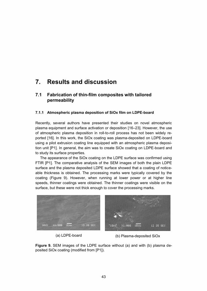
43
7. Results and discussion
7.1 Fabrication of thin-film composites with tailored permeability
7.1.1 Atmospheric plasma deposition of SiOx film on LDPE-board
Recently, several authors have presented their studies on novel atmospheric plasma equipment and surface activation or deposition [16–23]. However, the use of atmospheric plasma deposition in roll-to-roll process has not been widely re-ported [16]. In this work, the SiOx coating was plasma-deposited on LDPE-board using a pilot extrusion coating line equipped with an atmospheric plasma deposi-tion unit [P1]. In general, the aim was to create SiOx coating on LDPE-board and to study its surface properties.
The appearance of the SiOx coating on the LDPE surface was confirmed using FTIR [P1]. The comparative analysis of the SEM images of both the plain LDPE surface and the plasma deposited LDPE surface showed that a coating of notice-able thickness is obtained. The processing marks were typically covered by the coating (Figure 9). However, when running at lower power or at higher line speeds, thinner coatings were obtained. The thinner coatings were visible on the surface, but these were not thick enough to cover the processing marks.
(a) LDPE-board
(b) Plasma-deposited SiOx
Figure 9. SEM images of the LDPE surface without (a) and with (b) plasma de-posited SiOx coating (modified from [P1]).
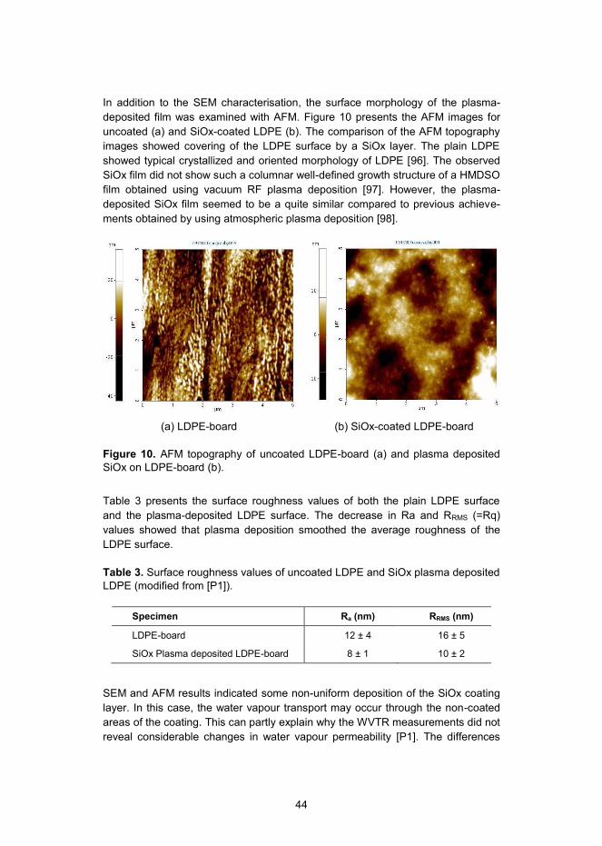
44
In addition to the SEM characterisation, the surface morphology of the plasma-deposited film was examined with AFM. Figure 10 presents the AFM images for uncoated (a) and SiOx-coated LDPE (b). The comparison of the AFM topography images showed covering of the LDPE surface by a SiOx layer. The plain LDPE showed typical crystallized and oriented morphology of LDPE [96]. The observed SiOx film did not show such a columnar well-defined growth structure of a HMDSO film obtained using vacuum RF plasma deposition [97]. However, the plasma-deposited SiOx film seemed to be a quite similar compared to previous achieve-ments obtained by using atmospheric plasma deposition [98].
(a) LDPE-board
(b) SiOx-coated LDPE-board
Figure 10. AFM topography of uncoated LDPE-board (a) and plasma deposited SiOx on LDPE-board (b).
Table 3 presents the surface roughness values of both the plain LDPE surface and the plasma-deposited LDPE surface. The decrease in Ra and RRMS (=Rq) values showed that plasma deposition smoothed the average roughness of the LDPE surface.
Table 3. Surface roughness values of uncoated LDPE and SiOx plasma deposited LDPE (modified from [P1]).
Specimen Ra (nm) RRMS (nm)
LDPE-board 12 ± 4 16 ± 5
SiOx Plasma deposited LDPE-board 8 ± 1 10 ± 2
SEM and AFM results indicated some non-uniform deposition of the SiOx coating layer. In this case, the water vapour transport may occur through the non-coated areas of the coating. This can partly explain why the WVTR measurements did not reveal considerable changes in water vapour permeability [P1]. The differences

45
between untreated, plasma-treated and plasma-deposited samples were within the limits of the standard deviation.
Further development of the plasma deposition process may improve the barrier performances. For example, more powerful plasma pre-treatment may be neces-sary to ensure better film formation. On the other hand, the LDPE surface is rather rough for deposition of uniform and dense thin films. Therefore, further research should focus on the effect of pre-treatment or primer layer in smoothing the LDPE surface prior to the plasma deposition. Moreover, a thicker SiOx coating layer might improve the barrier performance as well. However, it may lead to unwanted cracking of the inorganic coating layer. Therefore, a protective coating layer is possibly needed to improve the durability of the inorganic layer.
7.1.2 Atmospheric plasma-assisted sol-gel hybrid coating on LDPE-board
In relation to work on plasma-deposition of SiOx coatings, a pilot extrusion coating line was equipped with an atmospheric plasma pre-treatment unit. The main goal was to obtain high barrier effects for oxygen and grease by deposition of plasma-assisted sol-gel hybrid coatings on the LDPE-board [P2].
The sol-gel hybrid coatings consisted of either a 2-dimensional (SG204) or 3-dimensional (SG206) oligomer hybrid network. The SG204 coating was based on the 2D oligomer hybrid structure synthesised according to Figure 11, which illus-trates the reaction between metal alkoxide (e.g. tetraethoxysilane, TEOS) and organically modified alkoxysilane (e.g. octyltriethoxysilane, C8-TES). Typically, some of the hydroxyl groups remain unreacted or react more slowly depending on the catalysis of the reaction [25]. These hydroxyl groups can enhance the bonding of the synthesised hybrid coating on substrates bearing hydroxyl or carboxyl groups. Therefore, the hydrophobic functional end-groups of the organically modi-fied alkoxysilanes should align out from the substrate.

46
Figure 11. Synthesis of 2D oligomeric hybrid structure using sol-gel route.
The SG206 coating consisted of 3-glycidyloxypropyltrimethoxysilane and 3-(2-aminoethylamino) propyltrimethoxysilane. Figure 12 describes the synthesis route for formation of the 3D hybrid network, where an epoxy coupling reaction occurs between amino and epoxy groups, followed by methoxy group reaction through hydrolysis and condensation reactions to form the polysiloxane Si-O-Si bonds.
Figure 12. Synthesis of 3D oligomeric hybrid structure using epoxy coupling reac-tion and the sol-gel route.

47
The SEM analysis was used to characterise the structure and film thickness of the coated specimens. Figure 13 presents an SEM image of a cross-section of the SG206 coating deposited on the LDPE. The existence of the coating layer can be seen as a light grey colour. The coating thickness determined from the SEM im-age was approximately 1.3–1.5 µm. The SEM image indicated that the coating was uniform and dense. In addition, no film cracking was observed.
Figure 13. Cross-section SEM image of the SG206 coated LDPE-board.
Figure 14 presents the AFM topography images of (a) the uncoated LDPE-board and (b) the SG206-coated LDPE surface. Based on AFM images, the sol-gel coat-ing formed a smooth and dense layer on the LDPE surface. Furthermore, the average roughness (Ra) value for the sol-gel-coated LDPE (0.4 nm) was evidently lower in comparison to that of the uncoated LDPE-board (5.1 nm).
(a) LDPE-board
(b) SG206-coated LDPE-board
Figure 14. AFM topography images of (a) the uncoated and (b) the SG206-coated LDPE-boards.

48
Oxygen barrier
The oxygen barrier performance of the two different hybrid sol-gel coatings was studied by comparing their oxygen transmission rate (OTR) values. The aim was to demonstrate the effect of an additional coating layer on the oxygen barrier perfor-mance of LDPE. The coating chemistry was expected to have an effect on the permeability properties of the coatings. In addition, the effect of plasma pre-treatment on spreadability and uniformity of the film was studied by comparing OTR values between the coatings deposited with and without plasma pre-treatments.
Figure 15 presents the OTR of the uncoated LDPE and sol-gel coatings (SG204 and SG206) with and without plasma pre-treatment. The oxygen transmission rate of the LDPE-board was approximately 8700 cm3/(m2*atm*day). All the coated specimens had lower oxygen transmission in comparison to the uncoated LDPE-board. The comparison between the non-treated and the plasma-treated coatings showed some differences. The OTR values of the non-treated SG204 and SG206 coatings were 7100 and 6900 cm3/(m2*atm*day). The OTR values of the plasma-pretreated SG204 and SG206 coatings were 7100 and 900 cm3/(m2*atm*day), respectively.
Figure 15. The oxygen transmission rates (OTR) of LDPE-board and sol-gel coat-ings SG204 and SG206 with and without plasma pre-treatment on the LDPE sur-face (modified from [P2]).
The differences in the barrier performance between the coatings can be explained by the coating chemistry. The SG206 coating formed a denser organic network, where epoxy groups reacted with the amino groups, forming the 3-dimensional network. The SG204 coating did not form a similar network, due to the lack of reactive groups for the cross-linking. The results indicate that the plasma pre-treatment did not affect the barrier performance of the SG204 coating, whereas
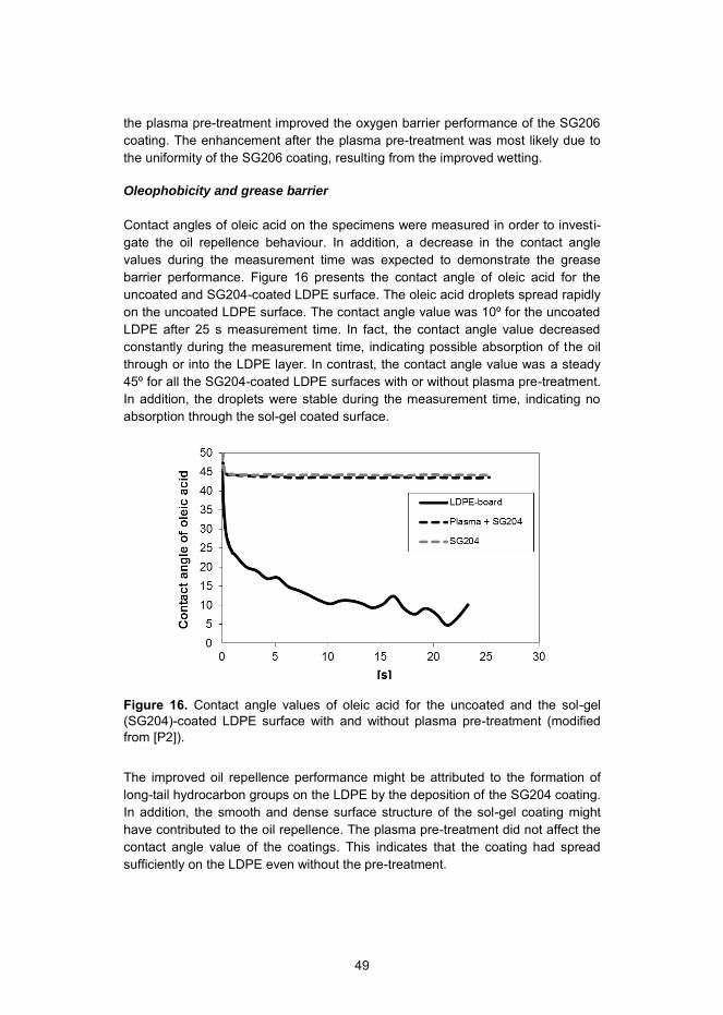
49
the plasma pre-treatment improved the oxygen barrier performance of the SG206 coating. The enhancement after the plasma pre-treatment was most likely due to the uniformity of the SG206 coating, resulting from the improved wetting.
Oleophobicity and grease barrier
Contact angles of oleic acid on the specimens were measured in order to investi-gate the oil repellence behaviour. In addition, a decrease in the contact angle values during the measurement time was expected to demonstrate the grease barrier performance. Figure 16 presents the contact angle of oleic acid for the uncoated and SG204-coated LDPE surface. The oleic acid droplets spread rapidly on the uncoated LDPE surface. The contact angle value was 10º for the uncoated LDPE after 25 s measurement time. In fact, the contact angle value decreased constantly during the measurement time, indicating possible absorption of the oil through or into the LDPE layer. In contrast, the contact angle value was a steady 45º for all the SG204-coated LDPE surfaces with or without plasma pre-treatment. In addition, the droplets were stable during the measurement time, indicating no absorption through the sol-gel coated surface.
Figure 16. Contact angle values of oleic acid for the uncoated and the sol-gel (SG204)-coated LDPE surface with and without plasma pre-treatment (modified from [P2]).
The improved oil repellence performance might be attributed to the formation of long-tail hydrocarbon groups on the LDPE by the deposition of the SG204 coating. In addition, the smooth and dense surface structure of the sol-gel coating might have contributed to the oil repellence. The plasma pre-treatment did not affect the contact angle value of the coatings. This indicates that the coating had spread sufficiently on the LDPE even without the pre-treatment.
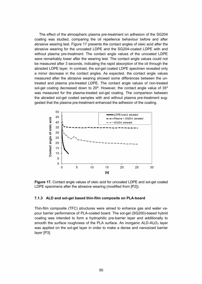
50
The effect of the atmospheric plasma pre-treatment on adhesion of the SG204 coating was studied, comparing the oil repellence behaviour before and after abrasive wearing test. Figure 17 presents the contact angles of oleic acid after the abrasive wearing for the uncoated LDPE and the SG204-coated LDPE with and without plasma pre-treatment. The contact angle values of the uncoated LDPE were remarkably lower after the wearing test. The contact angle values could not be measured after 3 seconds, indicating the rapid absorption of the oil through the abraded LDPE layer. In contrast, the sol-gel coated LDPE specimen revealed only a minor decrease in the contact angles. As expected, the contact angle values measured after the abrasive wearing showed some differences between the un-treated and plasma pre-treated LDPE. The contact angle values of non-treated sol-gel coating decreased down to 20º. However, the contact angle value of 35º was measured for the plasma-treated sol-gel coating. The comparison between the abraded sol-gel coated samples with and without plasma pre-treatment sug-gested that the plasma pre-treatment enhanced the adhesion of the coating.
Figure 17. Contact angle values of oleic acid for uncoated LDPE and sol-gel coated LDPE specimens after the abrasive wearing (modified from [P2]).
7.1.3 ALD and sol-gel based thin-film composite on PLA-board
Thin-film composite (TFC) structures were aimed to enhance gas and water va-pour barrier performance of PLA-coated board. The sol-gel (SG200)-based hybrid coating was intended to form a hydrophilic pre-barrier layer and additionally to smooth the surface roughness of the PLA surface. An inorganic ALD-Al2O3 layer was applied on the sol-gel layer in order to make a dense and nanosized barrier layer [P3].

51
Figure 18 presents AFM topography images of (a) PLA-board and TFC struc-tures, (b) SG200/PLA-board, and (c) ALD/SG200/PLA-board. The TFC structure was formed by applying the SG200 coating on the PLA-board, which was followed by a coating of ALD-Al2O3 layer. Indeed, the SG200 coating, as a pre-barrier layer covered the larger valleys, pinholes and pores of the PLA surface, making it denser and smoother. Therefore, the surface is more favourable for the ALD based Al2O3 barrier layers, which was intended to give further densification of the surface.
(a) Uncoated (b) SG200-coated (c) ALD/SG200-coated
Figure 18. AFM images of (a) uncoated PLA-board, and coated PLA-boards: (b) SG200 and (c) ALD/SG200.
Table 4 summarises the values for average surface roughness (Ra), water contact angle, OTR and the WVTR of uncoated, SG200-coated and ALD/SG200-coated PLA-boards. The Ra roughness results indicated that the SG200 coating reduced the Ra value making the PLA surface smoother. In addition, the SG200 coating reduced the water contact angle value indicating a more hydrophilic surface. The ALD-Al2O3 layer on top of the SG200 coating made the surface even smoother. However, some particle-like ALD growth as noticed, which has also been seen in other type of ALD experiments [78,79]. The total decrease in Ra was from 54 to 15 nm. Moreover, the water contact angle value dropped even further with the additional Al2O3 coating.
The high-barrier performance of the TFC structure was demonstrated using OTR and WVTR measurements. A minor improvement in the OTR and the WVTR values was obtained with the SG200 coating in comparison to plain PLA-board. A remarkable decrease in OTR and WVTR values was noticed after applying the ALD layer on top of the sol-gel layer. The lowest OTR and WVTR values of 2 cm3/(m2*atm*day) and 2 g/(m2 *day) were reached with the ALD/SG200 struc-ture. Apparently, the obtained OTR and WVTR values of the ALD/SG200 were lower than those achieved for the ALD coating without the sol-gel (OTR: 6 cm3/(m2*atm*day) and WVTR: 3 g/(m2 *day)).

52
Table 4. Values of water contact angle (WCA), average roughness (Ra) OTR and WVTR transmission of plain PLA-board and coated specimens SG200/PLA-board and ALD/SG200/PLA-board (modified from [P3]).
Specimen Ra [nm]
WCA [o]
OTR [cm3m-2atm-1day1]
WVTR [g m-2day-1]
Uncoated PLA-board 54 71 400±9 75±2
SG200-coated PLA-board 27 58 310±2 44±2
ALD/SG200-coated PLA-board 15 52 2±1 2±1
7.2 Surface modification of thin-film composites with anti-fouling performance
7.2.1 Characterisation of uncoated and coated thin-film composites
The surface properties and their effect on bacterial anti-adhesion performance were studied using uncoated and coated polyamide (PA) thin-film composite (TFC) membranes [P4]. All the membranes were commercially available fully-aromatic TFC-PA membranes. Two of the TFC-PA membranes (SW30 and BW30) were coated using polyvinyl alcohol (PVA) coating, while the other three membranes (LE, XLE and NF90) were uncoated. Table 5 summarises the results on root-mean-square surface roughness (RRMS), water contact angle and surface energies with total, polar and dispersive values. The PVA coated membranes (SW30HR and BW30) had a lower water contact angle and higher surface energy values in comparison to uncoated membranes (LE, XLE and NF90). Indeed, the most hydrophilic and highest surface energy was measured for the SW30HR membrane. In addition, SW30HR showed the highest polar surface energy value, among the characterised membranes. BW30 membrane had a slightly higher water contact angle and respectively, lower surface energy. Moreover, the polar surface energy of BW30 was somewhat lower than SW30HR. Based on the results, the PVA coating increased the polarity of the TFC-PA membrane surface.
Among the uncoated TFC-PA membranes, the LE membrane clearly had the lowest values for water contact angle and the highest for the surface energy re-spectively. The surface energy value for LE was almost at the same level with the coated membranes. However, comparison of polar surface energy values re-vealed that the LE membrane surface had a lower polarity. In contrast, among the characterised membranes the XLE and NF90 membranes showed most hydropho-bic and non-polar surface properties. In fact, the highest value for water contact angle and respectively, the lowest value for surface energy were measured for the XLE membrane. Similarly, the NF90 membrane showed hydrophobic surface prop-erties. The NF90 membrane had a slightly lower value for water contact angle value and a higher value for surface energy respectively in comparison to the XLE. How-ever, the polarity of XLE membrane was higher compared to NF90 membrane.

53
The RRMS roughness values for the coated membranes SW30HR and BW30 were somewhat lower in comparison to the uncoated membranes (LE, XLE and NF90). The slightly decreased roughness is most likely due to deposition of a very thin coating layer on the BW30 and SW30HR membranes. The coating layer might have filled the valleys of the PA selective layer. The high deviation in roughness may be explained by the uneven deposition of the coating. Among the uncoated TFC-PA membranes, LE and NF90 had a lower surface roughness than XLE. The uncoated membranes showed similarly high deviation of the roughness values. This can be explained by the differences in the formation of the PA selective layer, resulting in an uneven peak-and-valley surface structure.
Table 5. Summary of the results on water contact angle and surface energies.
Membrane WCA
[º]
Total surface energy
[mN/m]
Polar surface energy
[mN/m]
Dispersive surface energy
[mN/m]
RRMS
[nm]
SW30HR 28 ± 5 66 24 42 70 ± 12
BW30 43 ± 4 56 19 37 57 ± 5
LE 53 ± 9 54 11 43 75 ± 23
XLE 76 ± 5 38 4 34 96 ± 21
NF90 70 ± 4 42 2 40 76 ± 12
Bacterial anti-adhesion performance
Figure 19 presents the results of the bacteria viability analysis of the membrane samples after a 24 hour exposure to P. aeruginosa. The attachment of the bacte-ria was evidently different between the membranes. Indeed, the decrease in the number of viable cells can be observed simultaneously with the increase of hydro-philicity and surface polarity (Table 5). The lowest amount of bacteria was at-tached to the most hydrophilic and polar SW30HR and BW30 membranes. Among the uncoated membranes, the LE membrane had a somewhat lower amount of attached bacteria in comparison to the XLE and NF90 membranes. Indeed, the amount of bacteria found on the uncoated membrane surface increased in the order: LE, XLE and NF90.
The correlation between the polar surface energy and the attachment of bacte-ria was investigated in order to gain further knowledge of the effect of the surface energy on the attachment of bacteria. Apparently, the polar surface energy values clearly correlated with the attachment of the bacteria. The amount of bacteria decreased identically with the increase of polar surface energy value. In addition, the type of surface roughness may somehow contribute to bacteria repellence. However, an exact conclusion cannot be presented due to the heterogeneous surface topography of the membranes.

54
SW30HR BW30 LE XLE NF900,0
0,5
1,0
1,5
2,0
2,5
3,0
3,5
4,0
4,5
5,0
Via
ble
P. a
erug
inos
a ce
lls
(Log
CFU
cm
-2)
Figure 19. Viable P. aeruginosa cells on different membrane surfaces after 24 hour exposure.
7.2.2 PVA- and PVA-PHMG-coated thin-film composites
Anti-adhesion surfaces can be prepared using contact active amphiphilic, microbe-repelling or anti-adhesive polymers [67,68,69]. In addition, active antimicrobial coatings with bactericidal effects have been prepared using heavy metal nanopar-ticles, such as silver, copper and zinc [99,100]. However, the heavy metal-based antimicrobial coatings may have certain disadvantages: (1) uncontrolled leaching of the metal ions to the surroundings reduces the self-life of the anti-fouling mem-brane, and (2) these metal ions may raise questions concerning their safety to environment. In this regard, polymer based antimicrobial coatings may be fa-voured. The current study aimed to develop a surface coating method to enhance the anti-biofouling performance of TFC-PA RO membranes. Polyvinyl alcohol (PVA) and cationic polyhexamethyleneguanidine hydrochloride (PHMG) coatings were used to obtain hydrophilic and smooth surfaces to enhance membrane anti-adhesion properties [P5]. The PVA and PVA-PHMG coatings were coated on commercial LE-400 membrane. LE-400 is relatively high-permeable RO mem-brane and thus it was expected to be suitable for coating trials.
Surface chemistry of PVA and PVA-PHMG coatings
The surface chemistry of the PVA- and the PVA-PHMG-coated TFC-PA mem-branes was characterised using FTIR. Figure 20 shows the ATR-FTIR spectrum of the uncoated membrane and PVA-, PVA-PHMG- and PHMG-coated membranes in the range of 2000–500 and 4000–2600 cm-1. The uncoated membrane showed the typical FTIR spectrum of fully aromatic PA membranes formed from m-phenylenediamine and trimesoyl chloride on top of a polyethersulfone (PES) sup-port layer [64]. The peak at 1608 cm-1 was assigned to the C=O stretching (amide I band), and the peak at 1540 cm-1 was assigned to N-H bending (amide II band)
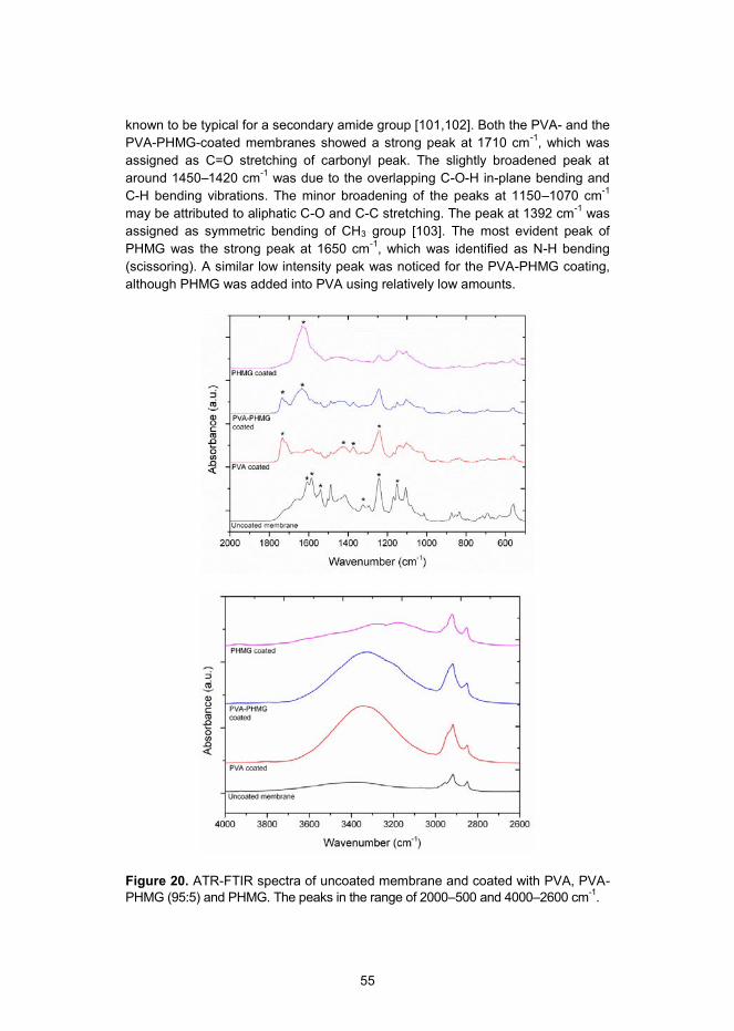
55
known to be typical for a secondary amide group [101,102]. Both the PVA- and the PVA-PHMG-coated membranes showed a strong peak at 1710 cm-1, which was assigned as C=O stretching of carbonyl peak. The slightly broadened peak at around 1450–1420 cm-1 was due to the overlapping C-O-H in-plane bending and C-H bending vibrations. The minor broadening of the peaks at 1150–1070 cm-1 may be attributed to aliphatic C-O and C-C stretching. The peak at 1392 cm-1 was assigned as symmetric bending of CH3 group [103]. The most evident peak of PHMG was the strong peak at 1650 cm-1, which was identified as N-H bending (scissoring). A similar low intensity peak was noticed for the PVA-PHMG coating, although PHMG was added into PVA using relatively low amounts.
Figure 20. ATR-FTIR spectra of uncoated membrane and coated with PVA, PVA-PHMG (95:5) and PHMG. The peaks in the range of 2000–500 and 4000–2600 cm-1.
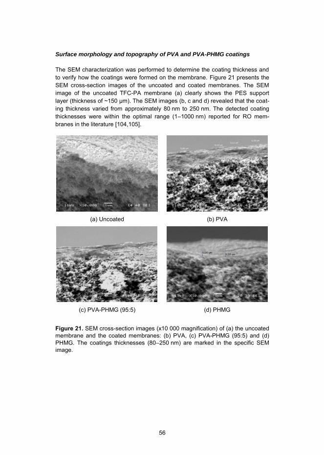
56
Surface morphology and topography of PVA and PVA-PHMG coatings
The SEM characterization was performed to determine the coating thickness and to verify how the coatings were formed on the membrane. Figure 21 presents the SEM cross-section images of the uncoated and coated membranes. The SEM image of the uncoated TFC-PA membrane (a) clearly shows the PES support layer (thickness of ~150 µm). The SEM images (b, c and d) revealed that the coat-ing thickness varied from approximately 80 nm to 250 nm. The detected coating thicknesses were within the optimal range (1–1000 nm) reported for RO mem-branes in the literature [104,105].
(a) Uncoated
(b) PVA
(c) PVA-PHMG (95:5)
(d) PHMG
Figure 21. SEM cross-section images (x10 000 magnification) of (a) the uncoated membrane and the coated membranes: (b) PVA, (c) PVA-PHMG (95:5) and (d) PHMG. The coatings thicknesses (80–250 nm) are marked in the specific SEM image.

57
(a) Uncoated membrane (b) PVA
(c) PVA-PHMG (99:1) (d) PVA-PHMG (95:5)
(e) PHMG
Figure 22. AFM images of the (a) uncoated membrane and the coated mem-branes: (b) PVA, (c) PVA-PHMG (99:1) (d) PVA-PHMG (95:5) and (e) PHMG.
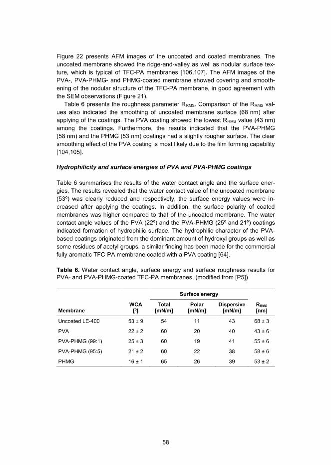
58
Figure 22 presents AFM images of the uncoated and coated membranes. The uncoated membrane showed the ridge-and-valley as well as nodular surface tex-ture, which is typical of TFC-PA membranes [106,107]. The AFM images of the PVA-, PVA-PHMG- and PHMG-coated membrane showed covering and smooth-ening of the nodular structure of the TFC-PA membrane, in good agreement with the SEM observations (Figure 21).
Table 6 presents the roughness parameter RRMS. Comparison of the RRMS val-ues also indicated the smoothing of uncoated membrane surface (68 nm) after applying of the coatings. The PVA coating showed the lowest RRMS value (43 nm) among the coatings. Furthermore, the results indicated that the PVA-PHMG (58 nm) and the PHMG (53 nm) coatings had a slightly rougher surface. The clear smoothing effect of the PVA coating is most likely due to the film forming capability [104,105].
Hydrophilicity and surface energies of PVA and PVA-PHMG coatings
Table 6 summarises the results of the water contact angle and the surface ener-gies. The results revealed that the water contact value of the uncoated membrane (53º) was clearly reduced and respectively, the surface energy values were in-creased after applying the coatings. In addition, the surface polarity of coated membranes was higher compared to that of the uncoated membrane. The water contact angle values of the PVA (22º) and the PVA-PHMG (25º and 21º) coatings indicated formation of hydrophilic surface. The hydrophilic character of the PVA-based coatings originated from the dominant amount of hydroxyl groups as well as some residues of acetyl groups. a similar finding has been made for the commercial fully aromatic TFC-PA membrane coated with a PVA coating [64].
Table 6. Water contact angle, surface energy and surface roughness results for PVA- and PVA-PHMG-coated TFC-PA membranes. (modified from [P5])
Membrane WCA
[º]
Surface energy
RRMS [nm]
Total [mN/m]
Polar [mN/m]
Dispersive [mN/m]
Uncoated LE-400 53 ± 9 54 11 43 68 ± 3
PVA 22 ± 2 60 20 40 43 ± 6
PVA-PHMG (99:1) 25 ± 3 60 19 41 55 ± 6
PVA-PHMG (95:5) 21 ± 2 60 22 38 58 ± 6
PHMG 16 ± 1 65 26 39 53 ± 2

59
Bacterial anti-adhesion performance of PVA and PVA-PHMG coated TFC-PA membranes
The attachment of the model biofilm-forming microorganism, P. aeruginosa, was studied in order to demonstrate the bacteria repellence performance of the un-coated and the coated membranes. The lower CFU values should indicate strong-er bactericidal effects or bacteria repellence (anti-adhesion). Figure 23 illustrates the presence of P. aeruginosa on uncoated and coated membranes. In general, the CFU test revealed that a lower number of P. aeruginosa had adhered to the coated membrane surfaces than to the respective uncoated membranes.
Among the colony counts of the coated membranes, the PHMG coating clearly showed the lowest number of viable cells of bacteria. It was also observed that the PVA-PHMG-coated membranes attracted a lower number of the bacteria com-pared to the PVA-coated membrane. The unmodified PVA coating clearly showed a minor bacteria repellence effect when compared to the PHMG modified coat-ings. Nevertheless, the CFU results evidently showed that the PVA-coated mem-brane attracted less bacteria compared to the uncoated membrane.
As a result of the physiochemical anti-fouling performance, the PVA coating re-vealed anti-adhesion and bacteria repellence performance. The effect of the sur-face properties can be seen on the attachment of bacteria, because of the evident correlation between the increase in hydrophilicity (Table 6) and correspondingly, the decrease in the attachment of the bacteria. Furthermore, the lowered surface roughness might have contributed to the attachment of the bacteria. The results are related to the similar trend detected for the commercial membranes in Figure 16. However, PVA-PHMG and PHMG coatings also showed hydrophilic and smoother surface roughness compared to uncoated membrane. In fact, the at-tachment of the bacteria decreased by the increase in the PHMG content in the surface. This suggested that the strongest effect on the attachment of bacteria was obtained by combining the antimicrobial activity with the physiochemical anti-adhesion surface properties.

60
Uncoated PVA PVA-PHMG (99:1)
PVA-PHMG (95:5)
PHMG 0
1
2
3
4
5
6
7
8
Atta
chm
ent o
f P. a
erug
inos
a(L
og C
FU c
m-2)
Figure 23. Attachment of P. aeruginosa on uncoated and coated membranes.
Antimicrobial performance of PVA and PVA-PHMG coated TFC-PA membranes
The membrane antimicrobial performance was studied by determining the number of the viable model bacteria, E. coli and B. subtilis, found on uncoated and coated membrane specimens. Figure 24 and Figure 25 present the CFU results of E. coli and B. subtilis, respectively. In Figure 24, the number of E. coli cells on the coated membranes was lower compared to that of the uncoated membrane. In addition, CFU test results of B. subtilis indicated similar behaviour, although the differences were not as significant (Figure 25). The trend in CFU changes was nevertheless consistent between the specimens. Furthermore, these CFU results showed a similar behaviour of the membrane specimens compared to the study of P. aeru-ginosa. The PHMG coating repeatedly showed the lowest number of viable cells of the bacteria, among the coated membranes. Similarly, the PVA-PHMG-coated membranes attracted a lower number of the bacteria when compared to the PVA-coated membrane. The results indicated that PHMG was somewhat more efficient against the Gram-negative E. coli. The unmodified PVA coating showed only mi-nor repellence effect on these bacteria compared to the PHMG modified coatings. However, the CFU results showed that the PVA-coated membrane attracted less bacteria to some extent, in comparison to the uncoated membrane, indicating an enhanced anti-adhesion performance.

61
Uncoated PVA PVA-PHMG (99:1)
PVA-PHMG (95:5)
PHMG 0
5000000
10000000
15000000
20000000
25000000
30000000
35000000
40000000E
. col
i (C
FU m
l-1)
Figure 24. CFU results of E. coli on uncoated and coated membranes.
Uncoated PVA PVA-PHMG (99:1)
PVA-PHMG (95:5)
PHMG 0
1000000
2000000
3000000
4000000
5000000
B. s
ubtil
is (C
FU m
l-1)
Figure 25. CFU results of B. subtilis on uncoated and coated membranes.

62
The diffusion inhibition zone (DIZ) test was conducted in order to further investi-gate the antimicrobial activity of the membrane specimens. An inhibition circle formed around a specimen would indicate antimicrobial activity and in addition, the leaching effect of the antimicrobial substance.
Figure 26 presents DIZ test results for Gram-negative E. coli bacteria and for Gram-positive B. subtilis bacteria. As expected, uncoated and PVA coated mem-branes did not show the formation of the inhibition circle against E. coli and B. subtilis; thus, the antimicrobial effect was not observed. The CFU results sug-gested that antimicrobial activity is obtained using PHMG. According to these results, the antimicrobial activity was more effective when the PHMG content was increased. However, the PVA-PHMG-coated membranes did not show the inhibi-tion circle against the bacteria. Nevertheless, the results clearly showed that the pure PHMG coating formed the inhibition circle against both of the bacteria, E. coli and B. subtilis, indicating antimicrobial activity. PHMG is known to have antimicro-bial performance [108,109]. The formation of a strong inhibition zone may also indicate leaching of the PHMG polymer, which might explain the lack of an inhibi-tion circle in the case of the PVA-PHMG coatings. The decrease in the attachment of bacteria was obtained by adding low amounts of PHMG in the PVA coating. The FTIR spectra revealed only low intensity peaks assigned to PHMG (Figure 20). Furthermore, the SEM and the AFM analysis as well as the contact angle measure-ments suggested that PHMG had a minor effect on the PVA coating morphology, surface texture and hydrophilicity (Table 6). In that respect, PHMG might be somehow encapsulated or consolidated into the PVA coating matrix. This could explain the stability of the PVA-PHMG coating, allowing PHMG to be active against bacteria. In particular, our aim was to prevent biofilm formation by developing a bacteria-repelling anti-adhesion surface with a contact-killing antimicrobial proper-ty, without leaching of the antimicrobial agent. The target was reached with PVA-PHMG coatings.
E. coli
(a) Uncoated membrane
B. subtilis
(b) Uncoated membrane
(c) PVA
(d) PVA
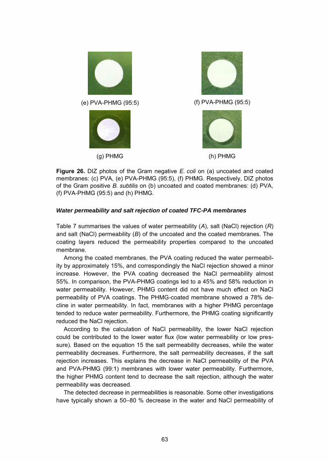
63
(e) PVA-PHMG (95:5)
(f) PVA-PHMG (95:5)
(g) PHMG
(h) PHMG
Figure 26. DIZ photos of the Gram negative E. coli on (a) uncoated and coated membranes: (c) PVA, (e) PVA-PHMG (95:5), (f) PHMG. Respectively, DIZ photos of the Gram positive B. subtilis on (b) uncoated and coated membranes: (d) PVA, (f) PVA-PHMG (95:5) and (h) PHMG.
Water permeability and salt rejection of coated TFC-PA membranes
Table 7 summarises the values of water permeability (A), salt (NaCl) rejection (R) and salt (NaCl) permeability (B) of the uncoated and the coated membranes. The coating layers reduced the permeability properties compared to the uncoated membrane.
Among the coated membranes, the PVA coating reduced the water permeabil-ity by approximately 15%, and correspondingly the NaCl rejection showed a minor increase. However, the PVA coating decreased the NaCl permeability almost 55%. In comparison, the PVA-PHMG coatings led to a 45% and 58% reduction in water permeability. However, PHMG content did not have much effect on NaCl permeability of PVA coatings. The PHMG-coated membrane showed a 78% de-cline in water permeability. In fact, membranes with a higher PHMG percentage tended to reduce water permeability. Furthermore, the PHMG coating significantly reduced the NaCl rejection.
According to the calculation of NaCl permeability, the lower NaCl rejection could be contributed to the lower water flux (low water permeability or low pres-sure). Based on the equation 15 the salt permeability decreases, while the water permeability decreases. Furthermore, the salt permeability decreases, if the salt rejection increases. This explains the decrease in NaCl permeability of the PVA and PVA-PHMG (99:1) membranes with lower water permeability. Furthermore, the higher PHMG content tend to decrease the salt rejection, although the water permeability was decreased.
The detected decrease in permeabilities is reasonable. Some other investigations have typically shown a 50–80 % decrease in the water and NaCl permeability of

64
coated membranes [110]. Therefore, in conditions where higher pressure is ap-plied or where the membrane has a reasonable permeability combination, the membrane is preferred in view of the better anti-fouling performance.
Table 7. Water permeability coefficient (A), salt (NaCl) rejection (R) and salt (NaCl) permeability coefficient (B) of the uncoated and the coated membranes.
Membrane
Water permeability coefficient
(A) [L/m2 h bar] a
Salt rejection
(R) [%] a
Salt permeability coefficient
(B) [L/m2 h] a
Uncoated LE-400 4.35 ± 0.48 97.2 ± 1.2 3.47 ± 1.87
PVA 3.71 ± 0.31 98.5 ± 0.6 1.53 ± 0.51
PVA-PHMG (99:1) 2.39 ± 0.60 98.2 ± 0.6 1.26 ± 0.70
PVA-PHMG (95:5) 1.67 ± 0.25 95.8 ± 2.2 2.17 ± 1.28
PHMG 0.76 ± 0.48 91.6 ± 0.3 2.30 ± 1.29
a Water flux (Jv) and salt rejection (R) of the membranes were evaluated using 10 mM NaCl feed solution and applied pressure of 27.6 bar (400 psi) at 23 ºC.
7.2.3 ALD-coated thin-film composites
The ALD coating was intended to modify the surface properties of the TFC-PA membrane and thus to improve anti-fouling performance. Two different processing temperatures (70ºC and 100ºC) and three different ALD cycles (10, 50 and 100) were used to deposit the ALD coatings on TFC PA membranes. The increase of ALD coating thickness and temperature may negatively affect the RO membrane performance by tightening the rejection layer of a temperature-sensitive polymeric membrane. Therefore, further understanding of the ALD process is needed in order to overcome the current drawbacks and to develop a new low-fouling RO membrane using the ALD technology. To the best knowledge of the author, the ALD method has not been applied for modification of RO membranes, and there-fore systematic study was needed to introduce ALD technology to the RO mem-branes [P6]. The ALD coatings were deposited on commercial LE-400 membrane.
Surface chemistry of ALD-coated TFC-PA membranes
FTIR was used to analyse the surface chemistry of the ALD-coated membranes. Figure 27 presents the FTIR spectra of the uncoated and the ALD-coated mem-branes in the range of 2000–500 cm-1. The FTIR spectra of the ALD-coated mem-branes showed most of the significant peaks assigned for PA (1660, 1610, and 1540 cm-1) and PES (1324, 1244 and 1180 cm-1), although the intensities of these peaks were reduced compared to the uncoated membrane. The decrease in the peak intensities was more prominent for the thicker coating layers, which can be explained by the dilution effect due to the presence of the coating material. In

65
addition, the decrease in the peak intensity at 1660 cm-1 and 1540 cm-1 might be partially attributed to the reaction of the TMA precursor with C=O groups of PA (to produce C-O-Al bonds) [31,32] and N-H groups (to form Al-N bonds) [31,32], re-spectively. In addition, the coated membranes showed the appearance of a new low intensity peak at 1150 cm-1, which may have originated from residues of unre-acted Al-CH3 groups of the TMA precursor [31,32].
2000 1800 1600 1400 1200 1000 800 600
*
*
*
*
*
*
*
*
*
*
*
*
*
*
*
*
*
*
Abs
orba
nce
(a.u
.)
c100_t70
c50_t70
c10_t70
Wavenumber (cm-1)
Uncoated
Figure 27. FTIR spectra of the uncoated and the ALD-coated (at 70ºC) speci-mens. The most significant peaks are marked with *.
Surface morphology and topography of ALD-coated TFC-PA membranes
The SEM characterization was performed to determine the surface morphology of the ALD-coated membranes. Figure 28 presents the SEM images of the uncoated and coated membranes. SEM images of the ALD-coated membranes (b–g) indicat-ed some changes in the surface morphology compared to the virgin membrane (a). The membranes coated at 100ºC generally looked tighter when compared to those coated at 70ºC. Moreover, a tightening of the ALD coating layer can be noticed due to an increase in the coating thickness. The tightening could cause significant hydraulic resistance of the coating layer and a decrease in RO perfor-mance.
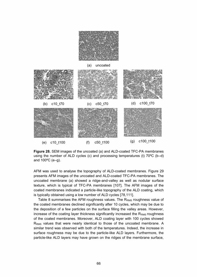
66
(a) uncoated
(b) c10_t70
(c) c50_t70
(d) c100_t70
(e) c10_t100
(f) c50_t100
(g) c100_t100
Figure 28. SEM images of the uncoated (a) and ALD-coated TFC-PA membranes using the number of ALD cycles (c) and processing temperatures (t) 70ºC (b–d) and 100ºC (e–g).
AFM was used to analyse the topography of ALD-coated membranes. Figure 29 presents AFM images of the uncoated and ALD-coated TFC-PA membranes. The uncoated membrane (a) showed a ridge-and-valley as well as nodular surface texture, which is typical of TFC-PA membranes [107]. The AFM images of the coated membranes indicated a particle-like topography of the ALD coating, which is typically obtained using a low number of ALD cycles [78,111].
Table 8 summarises the AFM roughness values. The RRMS roughness value of the coated membranes declined significantly after 10 cycles, which may be due to the deposition of a few particles on the surface filling the valley areas. However, increase of the coating layer thickness significantly increased the RRMS roughness of the coated membranes. Moreover, ALD coating layer with 100 cycles showed RRMS values that were nearly identical to those of the uncoated membrane. A similar trend was observed with both of the temperatures. Indeed, the increase in surface roughness may be due to the particle-like ALD layers. Furthermore, the particle-like ALD layers may have grown on the ridges of the membrane surface,

67
which could then promote the surface roughness. A similar roughness increase has been also noticed when applying other type of ALD coatings [111].
(a) uncoated
(b) c10_t70
(c) c50_t70
(d) c100_t70
(e) c10_t100
(f) c50_t100
(g) c100_t100
Figure 29. AFM images of the uncoated (a) and ALD-coated TFC-PA membranes using processing temperatures 70ºC (b–d) and 100ºC (e–g). Scan size 5x5 µm2 and Z-range 250 nm.
Hydrophilicity and surface energies of ALD-coated TFC-PA membranes
Hydrophilic properties of the uncoated and the ALD-coated TFC-PA membranes were studied using water contact angle measurements. These results are summa-rised in Table 8. The membranes became more hydrophilic when a thin ALD coat-ing layer was deposited on the membrane surface. The most hydrophilic mem-brane surface was obtained using 10 and 50 ALD cycles at 70ºC or 10 ALD cycles at 100ºC, having the water contact angles of ~ 15–30º compared to 53º for the uncoated membrane. This reduction in water contact angle can be attributed to the formation of a hydrophilic coating layer of Al2O3 with some residues of Al-OH

68
groups [111]. The membranes coated at 100ºC were generally less hydrophilic compared to those coated at 70ºC under otherwise identical conditions. This was probably due to the increase in reactivity and thus enhanced conversion of Al-OH to Al-O-Al at the higher temperature. Previous investigations have shown an in-crease in the reactivity of TMA precursor, when raising the temperature [31]. On the other hand, the number of ALD cycles was also seen to have an effect on water contact angles. The increase in hydrophobicity with the coating thickness might be due to the accumulation of hydrophobic alkyl residues (-CH3) as the TMA was not completely converted to Al2O3. The existence of Al-CH3 groups can be seen in FTIR spectra (Figure 27).
Table 8 also presents the surface energy measurement values. It was found that the surface energy was highly correlated to the contact angle – higher surface energy values were observed for membranes with lower contact angles. A closer analysis of the polar and non-polar components of the surface energy revealed that the increase in surface energy for the more hydrophilic membranes was mainly due to their higher polar contribution, whereas the non-polar contribution remained relatively constant. Once again, the increase in polarity may be attributed to the formation of Al-O-Al and Al-OH groups. The decrease in polarity for thicker coating layers may be due to the presence of significant amount of Al-CH3 groups.
Table 8. Surface properties of ALD-coated TFC-PA membrane including water contact angle, surface energy and surface roughness results. (modified from [P6])
Membrane WCA [o]
Total surface energy [mN/m]
Polar surface energy [mN/m]
Dispersive surface energy
[mN/m] RRMS [nm]
Uncoated LE-400 53 ± 9 54 11 43 73 ± 7
c10_t70 16 ± 4 67 33 34 50 ± 5
c50_t70 27 ± 1 57 21 36 56 ± 4
c100_t70 66 ± 2 38 10 28 75 ± 1
c10_t100 27 ± 5 44 11 33 54 ± 3
c50_t100 84 ± 4 39 1 38 69 ± 2
c100_t100 92 ± 1 34 1 33 71 ± 2
Bacterial anti-adhesion performance of ALD-coated TFC-PA membranes
The attachment of the model biofilm-forming microorganism, P. aeruginosa, onto uncoated and ALD-coated membranes was studied in order to demonstrate bacteria repellence performance. The test was only performed for the ALD-coated mem-branes processed at 70ºC (t70), because of their promising surface properties in comparison to the membranes coated at 100ºC (t100). Figure 30 presents the

69
number of adhered P. aeruginosa cells on uncoated and coated membranes. In general, a lower number of the adhered P. aeruginosa was detected on the ALD-coated membrane surfaces compared to the uncoated. Up to two log units reduc-tion in the number of adhered P. aeruginosa was detected on the thinner coatings with ALD cycles 10 (c10_t70) and 50 (c50_t70) compared to the uncoated mem-brane. The thicker coating with 100 ALD cycles (c100_t70) contained an almost equal number of viable cells as were detected on the uncoated membrane.
The ALD coating on the membrane created a surface with bacteria repellence performance, most likely due to the altered physiochemical properties of the membrane surface. The decrease in the number of adhered bacteria showed a strong correlation between the increase in surface hydrophilicity (Table 8) and the increase in surface polarity. For example, c10_t70 coatings (33.4 mN/m) had higher polarity compared to c50_t70 coatings (21.7 mN/m) and, fewer bacteria attached on former coatings. Moreover, c100_t70 coatings and uncoated mem-brane attracted bacteria in similar quantities and the surface polarity values of these were somewhat similar. The lower surface roughness of the thinner ALD coatings may have contributed to the attachment of the bacteria. Indeed, other researchers have shown that lower amount of P. aeruginosa bacteria were at-tached on model surfaces having nanotubular and nanotextured structure with a length of valleys and peaks 100–200 nm [112].
uncoated c10_t70 c50_t70 c100_t700
1
2
3
4
5
6
7
8
Atta
chm
ent o
f P.a
erug
inos
a Lo
g (C
FU c
m-2)
Figure 30. Attachment of P. aeruginosa bacteria on uncoated and ALD-coated (70ºC) membranes.

70
Water permeability and salt rejection of ALD-coated TFC-PA membranes
Table 9 summarises the values of water permeability (A), salt (NaCl) rejection (R) and salt (NaCl) permeability (B) of the uncoated and the coated membranes. These were measured only for the ALD-coated membranes processed at 70ºC.
Among the ALD-coated membranes, the thinner coatings with 10 and 50 ALD cycles (c10_t70 and c50_t70) did not show a significant effect on water permeabil-ity. Indeed, c10_t70 was marginally more permeable compared to the uncoated membrane. The sufficient water permeability of c10_t70 membranes could be explained by their hydrophilic character (Table 8) in addition to the low hydraulic resistance (Rc) due to the thin coating thickness. However, as a result of the ALD coating the NaCl rejection of these membranes was reduced and their NaCl per-meability (B) was increased. This may indicate an impact of the ALD coating on the PA rejection layer.
An increase in the ALD cycles had a strong effect on RO performance. Almost 65 % reduction of water permeability (A) was measured for the membrane with the thickest coating (c100_t70). This may be explained by the changes in the rejection layer, such as hydrophobicity and increase in the significant hydraulic resistance of the coating layer. Moreover, the salt permeability was reduced and the salt rejection was increased with increasing the coating thickness. This could be related to a tightening of the coating layer at increased coating thickness.
The trade-off between rejection and water permeability is typical for a coated membrane. For example, an additional ALD coating has been shown to form a hydraulic resistance layer on a porous polymeric membrane, which has typically reduced water permeability for 50–80 % and respectively, increased a solute re-tention for 10–30 % [78,80].
Table 9. Water permeability coefficient (A), salt (NaCl) rejection (R) and salt (NaCl) permeability coefficient (B) of the uncoated and the coated membranes.
Membrane
Water permeability coefficient
(A) [L/m2 h bar] a
Salt rejection
(R) [%] a
Salt permeability coefficient
(B) [L/m2 h] a
Uncoated LE-400 4.20 ± 0.11 95.5 ± 2.8 5.50 ± 3.34
c10_t70 4.63 ± 0.42 89.7 ± 4.6 15.05 ± 8.56
c50_t70 4.17 ± 0.56 89.1 ± 2.8 14.24 ± 5.50
c100_t70 1.52 ± 0.37 93.6 ± 2.0 2.98 ± 1.67
a Water flux (Jv) and salt rejection (R) of the membranes were evaluated using 10 mM NaCl feed solution and applied pressure of 27.6 bar (400 psi) at 23 ºC.

71
8. Conclusions
In this thesis, thin-film composites (TFC) were fabricated and modified using vari-ous coating methods. Firstly, the aim was to create a TFC packaging film with tailored permeability [P1–P3]. It was essential to study the effect of atmospheric plasma pre-treatment and sol-gel coating layer on the oxygen (O2) and water vapour (WV) permeability. In addition, the thesis investigated the effect of sol-gel coating composition on the O2 permeability and oil repellence. Secondly, the aim was to investigate the effects of surface properties on the anti-fouling performance of coated polyamide (PA) TFC membranes [P4–P6]. Polyvinyl alcohol (PVA) and atomic-layer-deposition (ALD) were used to enhance the anti-fouling performance of TFC-PA membrane. Both antimicrobial and anti-adhesion approaches were studied so as to gain further understanding of the anti-fouling tendency. The main conclusions of the thesis are the following:
SiOx coating was plasma-deposited on LDPE-boards. However, the SiOx coating did not improve the barrier performance of the LDPE-board. There-fore, a plasma-assisted sol-gel hybrid coating approach was considered for the LDPE-board. The composition of the two different sol-gel coatings (named SG204 and SG206) had an effect on barrier performances. The SG206 coating with more cross-linked 3D oligomer structure showed better O2 barrier performance in comparison to the SG204 coating with 2D oligomer structure. Nevertheless, the SG204 coating enhanced the oleophobicity of the LDPE-board, indicating improved grease barrier performance. The wet-tability and adhesion of the sol-gel coatings were enhanced when using the atmospheric plasma pre-treatment. Therefore, the plasma-activation of LDPE ensured the enhancement of O2 barrier performance for the SG206 coating and the grease barrier performance for the SG204 coating respec-tively. [P1–P2]
The sol-gel coating (named SG200) was deposited on the PLA-board to form a smooth and hydrophilic primer layer. Besides the primer function, the SG200 coating showed a moderate improvement of O2 and WV barrier. The ALD-Al2O3 layers were successfully deposited on top of the SG200 coating. The ALD coating further enhanced the O2 and WV barrier performances. In

72
fact, the TFC structure based on the ALD and sol-gel coatings had a some-what better barrier performance compared to a plain ALD coating. [P3]
Surface characterisation of commercially available uncoated and coated TFC-PA membranes revealed that the coating layer had a significant effect on the hydrophobicity, surface energy and roughness. In addition, the sur-face characterisation of experimental PVA-, PVA-PHMG- and ALD-coated TFC-PA membranes revealed an increase in the hydrophilicity and surface polarity. [P4–P6]
All the coated membranes had better anti-fouling performance in compari-son to uncoated TFC-PA membranes. The experimental PVA and ALD coatings showed anti-adhesion performance, showing a decrease in the at-tachment of the three model bacteria. The surface polarity correlated with the attachment of bacteria. The antimicrobial coatings with a higher PHMG percentage tended to have a higher bacteria-repellence and antimicrobial performance. CFU and DIZ results proved the antimicrobial performance of PHMG. [P4–P6]
The PVA-, PVA-PHMG and ALD coatings had an effect on permeability and rejection of the TFC-PA membranes. PVA and PVA-PHMG coatings reduced the water and salt permeability and also, increased the salt rejec-tion. Furthermore, the increase of the PHMG content showed a decrease in salt rejection. The thinner ALD coatings increased the water and salt per-meability and also, reduced the salt rejection. However, the thicker ALD coatings reduced the water and salt permeability, while the salt rejection was slightly increased. [P5–P6]
This study provides a basis for future development of TFC concepts with tailored permeability. Further research should focus on the effect of pre-treatment or pri-mer layers to smooth the rough and heterogeneous polymer surfaces prior to the deposition of nanoscale inorganic coatings. In addition, the use of organic or inor-ganic-organic protective coatings could be considered, in order to improve the durability of an inorganic coating layer. Furthermore, tailoring of the coating com-positions and combining of coating layer structures are expected to improve the barrier performance.
An optimal anti-fouling surface could be obtained by applying a coating, which is a combination of anti-adhesion and antimicrobial performances. However, further optimisation of the coating composition is needed in order to create the anti-fouling performance without sacrificing the RO performance. In addition, further studies should include long-term fouling studies of the coated TFC-PA membranes.
The ALD method has not been used for surface modification of RO membranes until now. Based on the first experiments, the ALD technology could be a promis-ing candidate to modify RO membranes. In fact, even a low thickness of ALD coating could modify the surface properties of the RO membrane by increasing the hydrophilicity and polarity as well as by lowering the surface roughness. These properties are essential improvements, especially for anti-fouling and permeability.

73
Despite the promising results obtained in this study, the parameters of the Al2O3-based ALD process need further investigation in order to find the balance between improved anti-fouling and RO performance. Moreover, investigations of other inorganic ALD chemistries are expected to provide new functionalities.
74
References
[1] M.F. Ashby and Y.J.M Bréchet, Designing hybrid materials, Acta Mater. 51 (2003) 5801–5821.
[2] G. Choudalakis and A.D. Gotsis, Permeability of polymer/clay nanocompo-sites: A review, Eur. Polym. J. 45 (2009) 967–984.
[3] L. Valentini and J.M. Kenny, Novel approaches to developing carbon nano-tube based polymer composites: fundamental studies and nanotech appli-cations, Polymer 46 (2005) 6715–6718.
[4] L.W. McKeen, Permeability properties of polymers and elastomers, 3rd
edition, Elsevier, USA, (2012). [5] N.S. Sangaj and V.C. Malshe, Permeability of polymers in protective organ-
ic coatings, Prog. Org. Coat. 50 (2004) 28–39.
[6] H.M.C. de Azeredo, Nanocomposites for food packaging applications, Food Res. Int. 42 (2009) 1240–1253.
[7] J.-C. Schotter and B. Bozkaya-Schotter, Current and emerging membrane processes for water treatment, in: K.-V. Peinemann and S.P. Nunes, Mem-branes for water treatment, vol. 4., Wiley-VCH, Weinheim, (2010) 53–88.
[8] A.G. Fane, C.Y. Tang and R. Wang, Membrane technology for water: Mi-crofiltration, ultrafiltration, nanofiltration and reverse Osmosis, Chapter 91, Elsevier, USA, (2010).
[9] R. Field, Fundamentals of fouling, in: K.-V. Peinemann and S.P. Nunes, Membranes for water treatment, vol. 4., Wiley-VCH, Weinheim, (2010) 1–23.
[10] D. Rana and T. Matsuura, Surface modifications for antifouling mem-branes, Chem. Rev. 110 (2010) 2448–2471.
[11] M. Ulbricht, Advanced functional polymer membranes, Polymer 47 (2006) 2217–2262.
[12] M. Stamm, Polymer surfaces and interfaces – characterization, modifica-tion and applications, First edition, Chapter 11 grafting on solid surfaces: “grafting to” and “grafting from” methods, Springer-Verlag Berlin Heidel-berg, (2008).

75
[13] D. Hegemann, H. Brunner and C. Oehr, Plasma treatment of polymers for surface and adhesion improvement, Nucl. Instr. Meth. Phys. 208 (2003) 281–286.
[14] C. Tendero, C. Tixier, P. Tristant, J. Desmaison and P. Leprince, Atmos-pheric pressure plasmas: A review, Spectrochim. Acta B 61 (2006) 2–30.
[15] Y.M. Chung, M.J. Jung, J.G. Han, M.W. Lee and Y.M. Kim, Atmospheric RF plasma effects on the film adhesion property, Thin Solid Films 354 (2004) 447–448.
[16] D. Vangeneugden, S. Paulussen, O. Goossens, R. Rego and K. Rose, Aerosol-assisted plasma deposition of barrier coatings using organic-inorganic sol-gel precursor systems, Chem. Vap. Depositions 11 (2005) 491–496.
[17] M. Pykönen, H. Sundqvist, O.-V. Kaukoniemi, M. Tuominen, J. Lahti, P. Fardim and M. Toivakka, Ageing effect in atmospheric plasma activation of paper substrates, Surf. Coat. Technol. 202 (2008) 3777–3786.
[18] M.H. Blees, G.B. Winkelman, A.R. Balkenende and J.M.J. den Toonder, The effect of friction on scratch adhesion testing: application to a sol–gel coating on polypropylene, Thin Solid Films 359 (2000) 1–13.
[19] O.-J. Kwon, S. Tang, S.-W. Myung, N. Lu and H.S. Choi, Surface charac-teristics of polypropylene film treated by an atmospheric pressure plasma, Surf. Coat. Technol. 192 (2005) 1–10.
[20] M.F Dubreuil and E.M. Bongaers, Use of atmospheric pressure plasma technology for durable hydrophilicity enhancement of polymeric substrates, Surf. Coat. Technol. 202 (2008) 5036–5042.
[21] D. Hegemann, H. Brunner and C. Oehr, Evaluation of deposition conditions to design plasma coatings like SiOx and a-C:H on polymers, Surf. Coat. Technol., 174–175 (2003) 253–260.
[22] G.R. Nowling, M. Yajima, S.E. Babayan, M. Moravej, X. Yang, W. Hoffman and R.F. Hicks, Chamberless plasma deposition of glass coatings on plastic. Plasma Sources Sci. Technol. 14 (2005) 477–484.
[23] S. Paulussen, R. Rego, O. Goossens, D. Vangeneugden and K. Rose. Plasma polymerization of hybrid organic–inorganic monomers in an atmos-
76
pheric pressure dielectric barrier discharge. Surf. Coat. Technol. 200 (2005) 672–675.
[24] M.R. De Geyter, N. Van Vlierberghe, S. Dubruel, P. Leys and C. Schacht, Deposition of polymethyl methacrylate on polypropylene substrates using an atmospheric pressure dielectric barrier discharge. Surf. Coat. Technol. 203 (2009) 1366–1372.
[25] C.J. Brinker and G.W. Scherer, Sol-Gel Science: The Physics and Chemistry of Sol-Gel Processing. Academic Press, Inc., San Diego (1990).
[26] C. Sanchez, B. Julián, P. Belleville and M. Popall, Applications of hybrid organic–inorganic nanocomposites. J. Mater. Chem. 15 (2005) 3559–3592.
[27] R. Puurunen, Surface chemistry of atomic layer deposition: A case study for the trimethylaluminum / water process. J. Appl. Phys. 97 (2005) 121301–121352.
[28] S. M. George, Atomic Layer Deposition: An Overview, Chem. Rev. 110 (2010) 111–131.
[29] M. Kemell, E. Färm, M. Ritala and M. Leskelä, Surface modification of thermoplastics by atomic layer deposition of Al2O3 and TiO2 thin films, Eur. Polym. J. 44 (2008) 3564–3570.
[30] G.K. Hyde, G. Scarel, J.C. Spagnola, Q. Peng, K. Lee, B. Gong, K.G. Roberts, K.M. Roth, C.A. Hanson, C. K. Devine, S.M. Stewart, D. Hojo, J. Na, J.S. Jur and G.N. Parsons, Atomic layer deposition and abrupt wetting transitions on nonwoven polypropylene and woven cotton fabrics, Langmuir 26 (2010) 2550–2558.
[31] J.C. Spagnola, B. Gong, S.A. Arvidson, J.S. Jur, S.A. Khan and G.N. Par-sons, Surface and sub-surface reactions during low temperature aluminium oxide atomic layer deposition on fiber-forming polymers, J. Mater. Chem. 20 (2010) 4213–4222.
[32] B. Gong and G.N. Parsons, Quantitative in situ infrared analysis of reac-tions between trimethylaluminum and polymers during Al2O3 atomic layer deposition, J. Mater. Chem. 22 (2012) 15672–15682.

77
[33] B. Gong, J.C. Spagnola, S.A. Arvidson, S.A. Khan and G.N. Parsons, Di-rected inorganic modification of bi-component polymer fibers by selective vapor reaction and atomic layer deposition, Polymer 53 (2012) 4631–4636.
[34] T. Hirvikorpi, R. Laine, M. Vähä-Nissi, V. Kilpi, E. Salo,W.-M. Lia, S. Lind-fors, J. Vartiainen, E. Kenttä, J. Nikkola, A. Harlin and J. Kostamo, Barrier properties of plastic films coated with Al203 by roll-to-roll ALD, Thin Solid Films 550 (2014) 164–169.
[35] ASTM D 3985 Standard test method for oxygen gas transmission rate through plastic film and sheeting using a coulometric sensor, ASTM Inter-national: West Conshohocken, PA.
[36] ASTM E 96 Standard test methods for water vapor transmission of materials, ASTM International: West, Conshohocken, PA.
[37] ISO 2528 Sheet materials – Determination of water vapor transmission rate – Gravimetric (dish) method, International Organization for Standardization: Geneva, Switzerland.
[38] TAPPI T 448 Water vapor transmission rate of sheet materials at standard temperature and humidity, TAPPI Press, Atlanta, GA.
[39] L.H. Ledenbach and R.T. Marshall, Microbiological spoilage of dairy prod-ucts, pp. 41–67, in W.H. Sperber, M.P. Doyle (eds) Compendium of the mi-crobiological spoilage of foods and beverages, Food microbiology and safety. Springer Science + Business Media, LLC, (2009).
[40] B. Nowak, K. Sammet, G. Klein and T. Mueffling, Trends in the production and storage of fresh meat- the holistic approach to bacteriological meat quality, Int. J. Food Sci. Technol. 41 (2006) 303–310.
[41] C.J. Weber, V. Haugaard, R. Festersen and G. Bertelsen, Production and applications of biobased packaging materials for the food industry, Food Addit. Contam. 19 (2002) 172–177.
[42] H. Ayvaz, S. Schirmer, Y. Parulekar, V.M. Balasubramaniam, J.A. Somer-ville and H. Daryaei, Influence of selected packaging materials on some quality aspects of pressureassisted thermally processed carrots during storage, LWT-Food Sci. Technol. 46 (2012) 437–447.
78
[43] J. Breil, Chapter 16 - Multilayer oriented films, in: J.R. Wagner Jr., Multi-layer flexible films, Elsevier, USA (2009) 231–237.
[44] T. Hirvikorpi, M. Vähä-Nissi, A. Harlin and M. Karppinen, Comparison of some coating techniques to fabricate barrier layers on packaging materials, Thin Solid Films 518 (2010) 5463–5466.
[45] T. Hirvikorpi, M. Vähä-Nissi, A. Harlin, J. Marles, V. Miikkulainen and M. Karppinen, Effect of corona pre-treatment on the performance of gas barrier layers applied by atomic layer deposition onto polymer-coated paperboard, Appl. Surf. Sci. 257 (2010) 736–740.
[46] C.F. Struller, P.J. Kelly, N.J. Copeland, V. Tobin, H.E. Assender, C.W. Holliday and S.J. Read, Aluminium oxide barrier films on polymeric web and their conversion for packaging applications, Thin Solid Films 553 (2014) 153–156.
[47] C.A. Bishop and E.M. Mount, Chapter 14 - Vacuum metallizing for flexible packaging, in J.R. Wagner Jr., Multilayer flexible films, Elsevier, USA, (2009) 185–202.
[48] K.-H. Haas, S. Amberg-Schwab, K. Rose and G. Schottner, Functionalized coatings based on inorganic-organic polymers (ORMOCER’s) and their combination with vapor deposited inorganic thin films, Surf. Coat. Technol. 111 (1999) 72–79.
[49] J.A. Redondo, Development and experience with new FILMTEC reverse osmosis membrane elements for water treatment, Desalination 108 (1996) 59–66.
[50] M. Al-Ahmad, F.A. Abdul Aleem, A. Mutiri and A.Ubaisy, Biofuoling in RO membrane systems Part 1: Fundamentals and control, Desalination 132 (2000) 173–179.
[51] C.Y. Tang , Y.-N. Kwon and J.O. Leckie, Fouling of reverse osmosis and nanofiltration membranes by humic acid – Effects of solution composition and hydrodynamic conditions, J. Membr. Sci. 290 (2007) 86–94.
[52] Y.N. Wang and C.Y. Tang, Protein fouling of nanofiltration, reverse osmosis, and ultrafiltration membranes – The role of hydrodynamic conditions, solution chemistry, and membrane properties, J. Membr. Sci. 376 (2011) 275–282.

79
[53] D. Norberg, S. Hong, J. Taylor and Y. Zhao, Surface characterization and performance evaluation of commercial fouling resistant low-pressure RO membranes, Desalination 202 (2007) 45–52.
[54] H.-C. Hemming, Reverse osmosis membrane biofouling, Exp. Therm. Fluid Sci. 14 4 (1997) 382–391.
[55] M. Herzberg and M.Elimelech, Biofouling of reverse osmosis membranes: Role of biofilm-enhanced osmotic pressure, J. Membr. Sci. 295 (2007) 11–20.
[56] M. Klausen, A. Heydorn, P. Ragas, L. Lambertsen, A. Aaes-Jørgensen, S. Molin and T. Tolker-Nielsen, Biofilm formation by Pseudomonas aeru-ginosa wild type, flagella and type IV pili mutants. Mol. Microbiol. 48 6 (2003) 1511–1524.
[57] H-C. Flemming and J. Wingender, The biofilm matrix, Nat. Rev. Microbiol. 8 (2010) 623–633.
[58] S.B. Sadr Ghayeni, P.J. Beatson, R.P. Schneider and A.G. Fane, Adhesion of waste water bacteria to reverse osmosis membranes, J. Membr. Sci. 138 (1998) 29–42.
[59] A. Subramani and E.M.V. Hoek, Biofilm formation, cleaning, re-formation on polyamide composite membranes, Desalination 257 (2010) 73–79.
[60] S. Kang, E.M.V. Hoek, H. Choi and H. Shin, Effect of membrane surface properties during the fast evaluation of cell attachment, Sep. Sci. Technol. 41 (2006) 1475–1487.
[61] M.M.T. Khan, P.S. Stewart, D.J. Moll, W.E. Mickols, S.E. Nelson and A.K. Camper, Characterization and effect of biofouling on polyamide reverse osmosis and nanofiltration membrane surfaces, Biofouling 27 2 (2011) 173–183.
[62] V. Chen, J. Mansouri and T. Charlton, Biofouling in membrane systems, in: K.-V. Peinemann and S.P. Nunes, Membranes for water treatment, Wiley-VCH, Weinheim, 4 (2010) 25–48.
[63] T. Nguyen, F.A. Roddick and L. Fan, Biofouling of water treatment mem-branes: A review of the underlying causes, monitoring techniques and control measures, Membranes 2 (2012) 804–840.

80
[64] C.Y. Tang, Y.-N. Kwon and J.O. Leckie, Effect of membrane chemistry and coating layer on physiochemical properties of thin film composite polyamide RO and NF membranes: I. FTIR and XPS characterization of polyamide and coating layer chemistry, Desalination 242 (2009) 149–167.
[65] H-L. Yang, J. Chun-Te Lin and C. Huang, Application of nanosilver surface modification to RO membrane and spacer for mitigating biofouling in sea-water desalination, Water Res. 42 (2009) 3777–3786.
[66] B.-H. Jeong, E.M.V. Hoeka, Y. Yan, A. Subramani, X. Huanga, G. Hurwitz, A.K. Ghosha and A. Jawor, Interfacial polymerization of thin film nanocom-posites: a new concept for reverse osmosis membranes, J. Membr. Sci. 294 (2007) 1–7.
[67] S. Belfer, Y. Purinson, R. Fainshtein, Y. Radchenko, and O. Kedem, Sur-face modification of commercial composite polyamide reverse osmosis membranes, J. Membr. Sci. 139 (1998) 175–181.
[68] J. Gilron, S. Belfer, P. Väisänen and M. Nyström, Effects of surface modifi-cation on antifouling and performance properties of reverse osmosis mem-branes, Desalination 140 (2001) 167–179.
[69] Y. Zhou, S. Yub, C. Gaoc and X. Fenga, Surface modification of thin film composite polyamide membranes by electrostatic self-deposition of poly-cations for improved fouling resistance, Sep. Purif. Technol. 66 (2009) 287–294.
[70] G. Kang, M. Liu, B. Lin, Y. Cao and Q. Yuan, A novel method of surface modification on thin-film composite reverse osmosis membrane by grafting poly(ethylene glycol), Polymer 48 (2007) 1165–1170.
[71] J.S. Louie, I. Pinnau, I. Ciobanu, K. P. Ishida, A. Ng and M. Reinhard, The Effects of polyether-polyamide block copolymer coating on performance and fouling of reverse osmosis membranes, J. Membr. Sci. 280 (2006) 762–770.
[72] S. Yu, Z. Lü, Z. Chena, X. Liua, M. Liua and C. Gaoc, Surface modification of thin-film composite polyamide reverse osmosis membranes by coating N-isopropylacrylamide-co-acrylic acid copolymers for improved membrane properties, J. Membr. Sci. 371 (2011) 293–306.
81
[73] T.D. Tran, S. Mori and M. Suzuki, Characteristics of polyimide-based com-posite membranes fabricated by low-temperature plasma polymerization, Thin Solid Films 516 (2008) 4384–4390.
[74] L. Zou, I. Vidalis, D. Steele, A. Michelmore, S.P. Low and J.Q.J.C. Verberk, Surface hydrophilic modification of RO membranes by plasma polymerization for low organic fouling, J. Membr. Sci. 369 (2011) 420–428.
[75] N. Kim, D. Ho Shin and Y. Taek Lee, Effect of silane coupling agents on the performance of RO membranes, J. Membr. Sci. 300 (2007) 224–231.
[76] D. Ho Shin, N. Kim and Y. Taek Lee, Modification to the polyamide TFC RO membranes for improvement of chlorine-resistance, J. Membr. Sci. 376 (2011) 302–311.
[77] C. Kong, A. Koushima, T. Kamada, T. Shintani, M. Kanezashi, T. Yoshioka and T. Tsuru, Enhanced performance of inorganic-polyamide nanocompo-site membranes prepared by metal-alkoxide-assisted interfacial polymeri-zation, J. Membr. Sci. 366 (2011) 382–388.
[78] Q. Xu, Y. Yang, X. Wang, Z. Wang, W. Jin, J. Huang and Y. Wang, Atomic layer deposition of alumina on porous polytetrafluoroethylene membranes for enhanced hydrophilicity and separation performances, J. Membr. Sci. 415–416 (2012) 435–443.
[79] F. Li, L. Li, X. Liao and Y. Wang, Precise pore size tuning and surface modifications of polymeric membranes using the atomic layer deposition technique, J. Membr. Sci. 385–386 (2011) 1–9.
[80] Q. Wang, X. Wang, Z. Wang, J. Huang and Y. Wang, PVDF membranes with simultaneously enhanced permeability and selectivity by breaking the trade off effect via atomic layer deposition of TiO2, J. Membr. Sci. 442 (2013) 57–64.
[81] F. Li, Y. Yang, Y. Fan, W. Xing and Y. Wang, Modification of ceramic membranes for pore structure tailoring: The atomic layer deposition route, J. Membr. Sci. 397–398 (2012) 17–23.
[82] M.A. Cameron, I.P. Gartland, J.A. Smith, S.F. Diaz and S.M. George, Atomic layer deposition of SiO2 and TiO2 in alumina tubular membranes:

82
Pore reduction and effect of surface species on gas transport, Langmuir 16 (2000) 7435–7444.
[83] CSID:6270, http://www.chemspider.com/Chemical-Structure.6270.html (accessed 07:43, Mar 16, 2014)
[84] CSID:16387, http://www.chemspider.com/Chemical-Structure.16387.html (accessed 08:04, Mar 16, 2014)
[85] CSID:68741, http://www.chemspider.com/Chemical-Structure.68741.html (accessed 07:39, Mar 16, 2014)
[86] CSID:14894, http://www.chemspider.com/Chemical-Structure.14894.html (accessed 07:37, Mar 16, 2014)
[87] B. Bolto, T. Tran, M. Hoang and Z. Xie, Crosslinked Poly(vinyl alcohol) Membranes, Progr. Polym. Sci. 34 (2009) 969–981.
[88] K. Grundke, Characterization of polymer surfaces by wetting and electroki-netic measurements – contact angle, interfacial tension, zeta potential, in: M. Stamm, Polymer surfaces and interfaces – Characterization, modifica-tion and applications, 1st Edition, Springer-Verlag Berlin Heidelberg (2008) 103–136.
[89] M. Klausen, A. Heydorn, P. Ragas, L. Lambertsen, A. Aaes-Jørgensen, S. Molin and T. Tolker-Nielsen, Biofilm formation by Pseudomonas aerugino-sa wild type, Flagella and type IV Pili Mutants, Mol. Microbiol. 48 6 (2003) 1511–1524.
[90] D1141-98 Standard practise for the preparation of substitute ocean water, (2008).
[91] M. Schaechter, Escherichia Coli, in M. Schaechter, Encyclopedia of micro-biology 3rd Edition, Elsevier, USA, (2009) 125–132.
[92] P.J. Piggot, Bacillus Subtilis, in M. Schaechter, Encyclopedia of microbiol-ogy 3rd Edition, Elsevier, USA, (2009) 45–56.
[93] Methods for dilution antimicrobial susceptibility tests for bacteria that grow aerobically, 9th ed. CLSI document M07-A9, Clinical Laboratory Standards Institute, Wayne, PA, 32 2 (2012).

83
[94] Performance standards for antimicrobial disk susceptibility tests; Approved standard, 9th ed, CLSI document M2-A9. Clinical Laboratory Standards In-stitute, Wayne, PA, 26 1 (2006).
[95] Y-N. Wang and C.Y. Tang, Protein fouling of nanofiltration, reverse osmo-sis, and ultrafiltration membranes – The role of hydrodynamic conditions, solution chemistry, and membrane properties, J. Membr. Sci., 376 (2011) 275–282.
[96] U. W. Gedde, Polymer physics, 1st ed., Kluwer Academic Publishers, Dor-drecht, The Netherlands, 1995, 154–155.
[97] A. Grüniger, A. Bieder, A. Sonnenfeld, Ph. Rudolf von Rohr, U. Müller and R. Hauert, Influence of film structure and composition on diffusion barrier performance of SiOx thin films deposited by PECVD, Surf. Coat. Technol. 200 (2006) 4564–4571.
[98] R. Morent, N. De Geyter, Sandra Van Vlierberghe, P. Dubruel, C. Leys and E. Schacht, Organic-inorganic behaviour of HMDSO films plasma-polymerized at atmospheric pressure, Surf. Coat. Technol. 203 (2009) 1366–1372.
[99] I. Sawada, R. Fachrul, T. Ito, Y. Ohmukai, T. Maruyama and H. Matsuya-ma, Development of a hydrophilic polymer membrane containing silver na-noparticles with both organic antifouling and antibacterial properties, J. Membr. Sci. 387–388 (2012) 1–6.
[100] S. Balta, A. Sotto, P. Luisa, L. Benea, B. Van der Bruggena and J. Kim, A new outlook on membrane enhancement with nanoparticles: the alternative of ZnO, J. Membr. Sci. 389 (2012) 155–161.
[101] R.M. Silverstein and F.X. Webster, Spectrometric identification of organic compounds, 6th Edition, John Wiley & Sons, Inc. New York (1997).
[102] N.B. Colthup, L.H. Daly and S.E. Wiberley, Introduction to infrared and raman spectroscopy, Academic Press Inc. New York (1975).
[103] H.S. Mansur, C.M. Sadahira, A.N. Souza and A.A.P. Mansur, FTIR spec-troscopy characterization of poly (vinyl alcohol) hydrogel with different hy-drolysis degree and chemically crosslinked with glutaraldehyde, Mater. Sci. Eng. 28 (2008) 539–548.

84
[104] H. Hachisuka and K. Ikeda, Composite reverse osmosis membrane having a separation layer with polyvinyl alcohol coating and method of reverse osmosis treatment of water using the same. (2001) US Patent 6177011 B1.
[105] I.C. Kim and K.H. Lee, Dyeing process wastewater treatment using fouling resistant nanofiltration and reverse osmosis membranes, Desalination 192 (2006) 246–251.
[106] C.Y. Tang, Y.-N. Kwon and J.O. Leckie, Effect of membrane chemistry and coating layer on physiochemical properties of thin film composite polyamide RO and NF membranes II – Membrane physiochemical properties and their dependence on polyamide and coating layers, Desalination 242 (2009) 168–182.
[107] K.C. Khulbe, C.Y. Feng and T. Matsuura, Synthetic polymeric membranes – characterisation by atomic force microscopy, Springer-Verlag Berlin Hei-delberg (2008) 157–167.
[108] O.J. Schmidt, A Schmidt and D. Toptchiev, Biocidal polymers based on guanidine salts. (2006) US Patent 7001606.
[109] Z.X. Zhou, D.F. Wei, Y. Guan, A.N. Zheng and J.J. Zhong, Damage of Escherichia coli membrane by bactericidal agent polyhexamethylene guan-idine hydrochloride: Micrographic evidences, J. Appl. Microbiol. 108 (2010) 898–907.
[110] J.S. Louie, I. Pinnau, I. Ciobanu, K.P. Ishida, A. Ng and M. Reinhard, Effects of polyether-polyamide block copolymer coating on performance and fouling of reverse osmosis membranes, J. Membr. Sci. 280 (2006) 762–770.
[111] N.P. Kobayashi, C. L. Donley, S. Wang and R.S. Williams, Atomic layer deposition of aluminium oxide on hydrophobic and hydrophilic surfaces, J. Cryst. Growth 299 (2007) 218–222.
[112] S.D. Puckett, E. Taylor, T. Raimondo and T. J. Webster, The relationship be-tween the nanostructure of titanium surfaces and bacterial attachment, Bio-materials 31 (2010) 706–713.

PUBLICATION P1
Reel-to-reel inline atmospheric plasma deposition of
hydrophobic coatings
In: Journal of Coatings Technology and Research 8(2)2011, pp. 237–245.Copyright ACA and OCCA 2010.
Reprinted with kind permission from Springer Science and Business Media.
Publication P1 of this publication is not included in the PDF version.


PUBLICATION P2
Raising the barriers Nano-layer enhances resistance properties
of polyethylene laminate
In: European Coatings Journal (1), pp. 41–47.Copyright 2011 Vincentz Network GmbFI & Co.
Reprinted with permission from the publisher.

II/1
Technical PaperPackaging coatings
41www.european-coatings.com 01 l 2011 European Coatings JOURNAL
Juha Nikkola
Two sol-gel coatings were studied as barrier coat-ings on polyethylene-coated paper used in packag-ing applications. Smooth dense films were formed, but plasma pre-treatment was essential to ensure good adhesion and functional properties. Sub-stantial performance differences were observed between the hydrophobically functionalised coating and the hydrophilically functionalised one.
The traditional packaging film materials, non-polar polypropylene (PP) and polyethylene (PE) are used in several industrial packaging applications. How-
ever, economic pressures and competition have created a trend towards a need for superior and multifunctional performances with even higher line speeds.The ever-increasing demands on product properties combined with faster line speeds make it challenging to achieve the level of adhesion required for thin coat-ings in particular. In order to meet these challenges, new surface activation methods and functional coatings on paper, paperboard or plastic films have been developed to provide special or enhanced properties in the field of paper converting [1].During the last ten years there has been general interest in studying the potential of organic-inorganic hybrid sol-gel thin films. The sol-gel process involves the develop-ment of nanoscale networks in a continuous liquid phase through the formation of a colloidal suspension and the subsequent gelation of the sol [2].
Sol-gel reactions summarisedHydrolysis acts as a rapid initial reaction of the sol-gel process, where reactive alkoxide groups react with water molecules to form hydroxyl groups. Equation (1) repre-sents the hydrolysis, where M is usually silicon, zirconium or titanium and n generally equals four.
(1)
After the initiation of the reaction, the hydrolysed alkox-ides react easily with each other and produce the back-bone of the sol-gel network. Water or alcohol is obtained as a by-product, depending on the reaction mechanism. The condensation reactions are explained by Equations (2) and (3).
(2)
(3)
Raising the barriersNano-layer enhances resistance properties of polyethylene laminate
* Corresponding author:Juha NikkolaVTT Technical Research Centre of FinlandJuha,[email protected]
Through these reactions the sol-gel technique offers op-portunities to produce premium functional and transpar-ent thin films.
Plasma technologies enhance coating adhesion
When using non-polar plastics such as polypropylene or polyethylene as the base material, it is necessary to in-crease the surface energy, by plasma pre-treatment for example, to obtain adhesion. One of the oldest industrial applications of plasma surface activation is corona treat-ment. The corona system does have certain limitations, though it has greatly evolved. For instance, the surface-activation effect of the corona is not stable and the use of plasma chemistry with different chemicals or gases is limited.Dielectric barrier discharge (DBD) plasmas were origi-nally created to eliminate the inhomogeneity of the sur-face treatment in the corona discharge [3]. The system is based on a dielectric layer covering at least one of the electrodes used. This generates a random distribution of streamers and a diffuse plasma, with a non-localised treatment effect. Other methods to generate the plasma include radio frequency (RF) plasma and microwave in-duced plasma (MIP).RF plasma is based on a capacitive or inductive match-ing of the impedance in the system, with a time-varying magnetic field subsequently creating an electric ring field which excites the electrons and produces plasma [4]. In MIP, the plasma is produced in an electrodeless manner, by the microwaves which ionise the gas used and further support the propagation of the microwaves.One of the main drawbacks of conventional DBD sys-tems for surface modification is the risk of damage and/or back treatment of the substrate by direct plasma in-teraction. Due to these limitations in traditional corona or plasma techniques, cold or non-equilibrium atmospheric pressure plasmas have been studied and developed.In addition, the search for new functionalities on paper surfaces has initiated research into novel atmospheric plasma applications for paper products. Recently, sev-eral authors have presented their studies on novel at-mospheric plasma equipment and surface activation or deposition [5, 6, 7].
Plasma treatments tested in similar applications
The sol-gel technique with atmospheric plasma pre-treatment has proved to be a potential method to pro-duce functional sol-gel thin films on reel-to-reel products [8, 9]. The use of atmospheric pressure plasma to obtain hybrid inorganic-organic barrier coatings on polyethylene terephthalate (PET) films has also been studied [10]. The
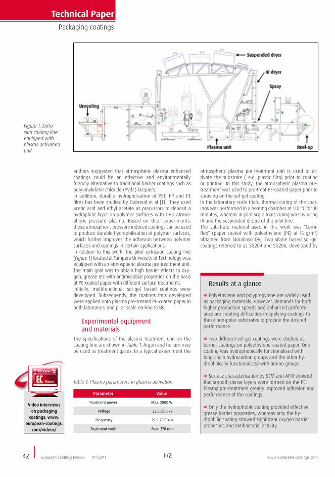
II/2 II/3www.european-coatings.com European Coatings JOURNAL
VTT Technical Research Centre of Finland, were prepared through hydrolysis and condensation reactions.SG204 was functionalised with long-chain hydrocarbon groups (hydrophobic coating) and SG206 with amino groups (hydrophilic coating), respectively. The sol-gel coatings were applied by spray coating and cured by heat as described above.
Test procedures summarisedThe oil and grease resistance of the specimens was studied by contact angle measurements with oleic acid. In addition, the effect of abrasive wear on the oil repellency was studied by a standard paint wash-ing tester apparatus (modified standard DIN 53778), where a brush was used as an abrasive material (1000 abrasion cycles). Abrasion resistance was evaluated by comparing the contact angle values before and af-ter the test.Oxygen transmission rate of the coated samples was measured with a “Model 8001” oxygen permeation ana-lyser from Systech Instruments Ltd. The oxygen trans-mission rate was measured at room temperature (23 °C) and with three different relative humidities: 0, 50, and 80 % RH.A “JEOL JSM-6360LV” scanning electron microscope (SEM) was used to characterise the surface structure of sol-gel coated samples. The surface topography was analysed by atomic force microscopy (AFM) with a Park Systems “XE-100” using non-contact mode.Antimicrobial activity was determined as described in standard JIS Z 2801: 2000 “Antimicrobial products - test for antimicrobial activity and efficacy”. Bacterial suspensions of gram positive Staphylococcus aureus and gram negative Escherichia coli containing approx-imately 1×10⁶ colony forming units/ml of test bacteria were placed on the surface of the specimen and incu-bated for 24 h at 35 °C.After incubation the bacteria were washed from the sam-ples and the number of viable bacteria was measured by
Figure 2: SEM cross-section image of amino-based sol-gel coating on PE-coated paper
15%May not sound much but it is the amount of
titanium dioxide you could save in your decorative coating by using an opacifying extender
Imerys offers a unique range of opacifying extenders for saving TiO
2
Imerys’ opacifying extenders allow the replacement of up to 15% of the TiO
2
in a paint without any loss of opacity or other key properties.
This allows the paint manufacturer to reduce its total titanium dioxide requirement, while at the same time allowing savings in the raw material cost per litre of paint.
THE APPLICATION OF MINERAL SCIENCE www.imerys-perfmins.com
See us at ECS, Hall 7, Stand 435
Technical PaperPackaging coatings
42 European Coatings JOURNAL 01 l 2011 www.european-coatings.com
Video interviews on packaging
coatings: www.european-coatings.
com/videos/
Results at a glance
Polyethylene and polypropylene are widely used as packaging materials. However, demands for both higher production speeds and enhanced perform-ance are creating difficulties in applying coatings to these non-polar substrates to provide the desired performance.
Two different sol-gel coatings were studied as barrier coatings on polyethylene-coated paper. One coating was hydrophobically functionalised with long-chain hydrocarbon groups and the other hy-drophilically functionalised with amino groups.
Surface characterisation by SEM and AFM showed that smooth dense layers were formed on the PE. Plasma pre-treatment greatly improved adhesion and performance of the coatings.
Only the hydrophobic coating provided effective grease barrier properties, whereas only the hy-drophilic coating showed significant oxygen barrier properties and antibacterial activity.
authors suggested that atmospheric plasma enhanced coatings could be an effective and environmentally friendly alternative to traditional barrier coatings such as polyvinylidene chloride (PVdC) lacquers.In addition, durable hydrophilisation of PET, PP and PE films has been studied by Dubreuil et al [11]. They used acetic acid and ethyl acetate as precursors to deposit a hydrophilic layer on polymer surfaces with DBD atmos-pheric pressure plasma. Based on their experiments, these atmospheric pressure induced coatings can be used to produce durable hydrophilisation of polymer surfaces, which further improves the adhesion between polymer surfaces and coatings in certain applications.In relation to this work, the pilot extrusion coating line (Figure 1) located at Tampere University of Technology was equipped with an atmospheric plasma pre-treatment unit. The main goal was to obtain high barrier effects to oxy-gen, grease etc with antimicrobial properties on the basis of PE-coated paper with different surface treatments.Initially, multifunctional sol-gel based coatings were developed. Subsequently, the coatings thus developed were applied onto plasma pre-treated PE-coated paper in both laboratory and pilot scale on-line trials.
Experimental equipment and materials
The specifications of the plasma treatment unit on the coating line are shown in Table 1. Argon and helium may be used as treatment gases. In a typical experiment the
Figure 1: Extru-sion coating line equipped with plasma activation unit
atmospheric plasma pre-treatment unit is used to ac-tivate the substrate ( e.g. plastic film) prior to coating or printing. In this study, the atmospheric plasma pre-treatment was used to pre-treat PE-coated paper prior to spraying on the sol-gel coating.In the laboratory scale trials, thermal curing of the coat-ings was performed in a heating chamber at 110 °C for 10 minutes, whereas in pilot scale trials curing was by using IR and the suspended dryers of the pilot line.The substrate material used in this work was “Lumi-flex” (paper coated with polyethylene (PE) at 15 g/m2) obtained from StoraEnso Oyj. Two silane based sol-gel coatings referred to as SG204 and SG206, developed by
Parameter Value
Treatment power Max. 2000 W
Voltage 22.5–25.0 kV
Frequency 21.5–25.0 kHz
Treatment width Max. 370 mm
Table 1: Plasma parameters in plasma activation
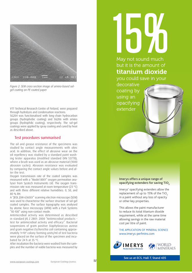
II/3www.european-coatings.com European Coatings JOURNAL
VTT Technical Research Centre of Finland, were prepared through hydrolysis and condensation reactions.SG204 was functionalised with long-chain hydrocarbon groups (hydrophobic coating) and SG206 with amino groups (hydrophilic coating), respectively. The sol-gel coatings were applied by spray coating and cured by heat as described above.
Test procedures summarisedThe oil and grease resistance of the specimens was studied by contact angle measurements with oleic acid. In addition, the effect of abrasive wear on the oil repellency was studied by a standard paint wash-ing tester apparatus (modified standard DIN 53778), where a brush was used as an abrasive material (1000 abrasion cycles). Abrasion resistance was evaluated by comparing the contact angle values before and af-ter the test.Oxygen transmission rate of the coated samples was measured with a “Model 8001” oxygen permeation ana-lyser from Systech Instruments Ltd. The oxygen trans-mission rate was measured at room temperature (23 °C) and with three different relative humidities: 0, 50, and 80 % RH.A “JEOL JSM-6360LV” scanning electron microscope (SEM) was used to characterise the surface structure of sol-gel coated samples. The surface topography was analysed by atomic force microscopy (AFM) with a Park Systems “XE-100” using non-contact mode.Antimicrobial activity was determined as described in standard JIS Z 2801: 2000 “Antimicrobial products - test for antimicrobial activity and efficacy”. Bacterial suspensions of gram positive Staphylococcus aureus and gram negative Escherichia coli containing approx-imately 1×10⁶ colony forming units/ml of test bacteria were placed on the surface of the specimen and incu-bated for 24 h at 35 °C.After incubation the bacteria were washed from the sam-ples and the number of viable bacteria was measured by
Figure 2: SEM cross-section image of amino-based sol-gel coating on PE-coated paper
15%May not sound much but it is the amount of
titanium dioxide you could save in your decorative coating by using an opacifying extender
Imerys offers a unique range of opacifying extenders for saving TiO
2
Imerys’ opacifying extenders allow the replacement of up to 15% of the TiO
2
in a paint without any loss of opacity or other key properties.
This allows the paint manufacturer to reduce its total titanium dioxide requirement, while at the same time allowing savings in the raw material cost per litre of paint.
THE APPLICATION OF MINERAL SCIENCE www.imerys-perfmins.com
See us at ECS, Hall 7, Stand 435

II/4 II/5
Technical PaperPackaging coatings
plasma pre-treatment alone on the oil repellency of the coating in Figure 4 was evident.On the other hand, the effect of plasma pre-treatment on the adhesion of the sol-gel coating can be seen in Figure 5. The decrease of the oil repellency after abrasive wear-ing of the untreated and sol-gel coated specimen can be seen by the decrease of contact angle value.The comparison between sol-gel coated samples with and without helium plasma pre-treatment showed that with the plasma pre-treated specimen the contact angle value decreased only slightly, whereas the value of the untreated sample decreased remarkably after wearing. This indicates that the adhesion of the coat-ing to the PE surface was clearly enhanced by plasma pre-treatment and furthermore the durability of grease barrier was also improved.With both specimens the contact angle value remained stable as a function of time, which means that absorp-tion of the oil did not occur. The contact angle value for the untreated PE surface could not be measured after three seconds, indicating rapid absorption of the oil into the abraded PE surface.
Oxygen barrier performance can be enhanced
The oxygen transmission rates (OTR) of both sol-gel coatings with and without plasma pre-treatment are
presented in Figure 6. The oxygen transmission rate for untreated polyethylene was approximately 8700 cm3/(m2
x 24 h) at 23 °C, 50 % RH. The additional sol-gel coating layer on top of the polyethylene film improved the oxy-gen barrier levels.
Figure 6: Oxygen transmission rates (OTR) of sol-gel coatings SG204 and SG206 with and without plasma pre-treatment on polyethylene coated paper (as reference)
European CoatingsConferences
Latest news on the Biocidal Pro-duct Directive
Solutions for dry-film and in-can preservation
Biocideds for antifouling paints
Biobased technology for UV coatings Sustainability in the focus of deve-
lopments The status quo for biobased and the
possibilities in the near future
Water repellent surfacs Sol-Gel technology with easy to clean performance Biomolecular responsive wettability switching Durability of nanostructured superhydrophobic coatings
Berlin/Germany
Nicole Steinbach · Project Manager Events
Tel. +49 511 9910-274 [email protected]
Coming up next!
Novel biocide technology 12/13 April 2011
Biobased Coatings II 10/11 February 2011
Easy-to-clean/self-cleaning coatings III 8/9 February 2011
Focusing on current developments in raw materials as well as mechanisms and standards the European Coatings Conferences will provide you with ideal networking opportunities and up-to-date information, presenting a suite of high-level technical papers, given by invited international experts.
Detailed programmes, abstracts and online registration at www.european-coatings.com
Extra
Pre-conference tutorials
Pictures: Patrizier-Design - Fotolia.com, ©Pixelio.comPaolo Toscani - Fotolia.com
Technical PaperPackaging coatings
44 European Coatings JOURNAL 01 l 2011 www.european-coatings.com
plating. Antimicrobial activity was determined according to standard JIS Z 2801 using uncoated polyethylene as a reference sample.
Smooth, dense coatings are obtained
An example of the coating thickness and structure of the amino-based sol-gel coating is presented in an SEM cross-section image in Figure 2. The coating was applied by on-line spray coating on PE-coated paper after argon plasma pre-treatment in reel-to-reel paper converting at a line speed of 60 m/min.
Figure 4: Contact angle values of oleic acid on test substrates before abrasive wearing
Figure 5: Contact angle values of oleic acid on test substrates after abrasive wearing.
The coating thickness determined from the SEM cross-section image is approximately 1.3 - 1.5 µm. Based on the SEM image, the coating has spread well and appears to be smooth and dense at the micro scale.Figure 3 shows the AFM surface characterisation images of untreated PE-coated paper (left) and the amino-based sol-gel (right) coated sample. The Ra roughness values for untreated PE-coated paper are 5.1 nm and Rz is 43.0 nm. For sol-gel coated surfaces the roughness values are clearly lower. The Ra value is 0.4 nm and Rz is 3.8 nm. The measurement area was 1µm x 1µm.These AFM results also show that the coating formed a smooth and dense layer on PE-coated paper in the nano scale.
Hydrophobic coating has good grease barrier properties
State-of-the-art coatings based on e.g. a fluorochemical [12] or on naturally-based chitosan [13] have been studied as grease barriers serving as an alternative or addition to polyolefin coatings on paper. For these fluorine-free coatings, the contact angles of oleic acid for untreated and sol-gel coated PE surfaces are presented in Figure 4.The rapid spreading of the oleic acid into the uncoated PE-coated paper took place during the measurement time of 25 seconds. The decrease of contact angle as a function of time also indicates possible absorption of oil into the specimen.On the other hand, the stable contact angle over time shows that absorption of oil into the sol-gel coated surface did not occur. The sol-gel matrix with hydro-phobic components displayed improved grease barri-er performance. It should be noted that the hydropho-bicity is not the only reason for these results, since the uncoated polyethylene surface is also relatively hydrophobic.The improved performance may be due to the smooth and dense surface structure of the sol-gel coating to-gether with the surface functionality introduced by long-chain hydrocarbon groups. However, it seems that the long-chain hydrocarbon groups also provide oil-repellent performance in addition to hydrophobicity. No effect of
Figure 3: AFM im-ages of untreated PE coated paper (left) and argon plasma enhanced amino-based coat-ing on PE coated paper (right); image size is 1 µm x 1 µm

II/5
Technical PaperPackaging coatings
plasma pre-treatment alone on the oil repellency of the coating in Figure 4 was evident.On the other hand, the effect of plasma pre-treatment on the adhesion of the sol-gel coating can be seen in Figure 5. The decrease of the oil repellency after abrasive wear-ing of the untreated and sol-gel coated specimen can be seen by the decrease of contact angle value.The comparison between sol-gel coated samples with and without helium plasma pre-treatment showed that with the plasma pre-treated specimen the contact angle value decreased only slightly, whereas the value of the untreated sample decreased remarkably after wearing. This indicates that the adhesion of the coat-ing to the PE surface was clearly enhanced by plasma pre-treatment and furthermore the durability of grease barrier was also improved.With both specimens the contact angle value remained stable as a function of time, which means that absorp-tion of the oil did not occur. The contact angle value for the untreated PE surface could not be measured after three seconds, indicating rapid absorption of the oil into the abraded PE surface.
Oxygen barrier performance can be enhanced
The oxygen transmission rates (OTR) of both sol-gel coatings with and without plasma pre-treatment are
presented in Figure 6. The oxygen transmission rate for untreated polyethylene was approximately 8700 cm3/(m2
x 24 h) at 23 °C, 50 % RH. The additional sol-gel coating layer on top of the polyethylene film improved the oxy-gen barrier levels.
Figure 6: Oxygen transmission rates (OTR) of sol-gel coatings SG204 and SG206 with and without plasma pre-treatment on polyethylene coated paper (as reference)
European CoatingsConferences
Latest news on the Biocidal Pro-duct Directive
Solutions for dry-film and in-can preservation
Biocideds for antifouling paints
Biobased technology for UV coatings Sustainability in the focus of deve-
lopments The status quo for biobased and the
possibilities in the near future
Water repellent surfacs Sol-Gel technology with easy to clean performance Biomolecular responsive wettability switching Durability of nanostructured superhydrophobic coatings
Berlin/Germany
Nicole Steinbach · Project Manager Events
Tel. +49 511 9910-274 [email protected]
Coming up next!
Novel biocide technology 12/13 April 2011
Biobased Coatings II 10/11 February 2011
Easy-to-clean/self-cleaning coatings III 8/9 February 2011
Focusing on current developments in raw materials as well as mechanisms and standards the European Coatings Conferences will provide you with ideal networking opportunities and up-to-date information, presenting a suite of high-level technical papers, given by invited international experts.
Detailed programmes, abstracts and online registration at www.european-coatings.com
Extra
Pre-conference tutorials
Pictures: Patrizier-Design - Fotolia.com, ©Pixelio.comPaolo Toscani - Fotolia.com

II/6 II/7
Technical PaperPackaging coatings
FDA (US Food and Drug Administration) acceptance. Therefore, at present these coatings should be used only in packaging applications where direct food con-tact can be avoided.
Surface chemistry is key to performance
In summary, two different kinds of sol-gel coatings for functional polyethylene packaging applications have been developed. The coatings were successfully applied onto PE by spray coating in a reel-to-reel paper converting process. The performance of the two coatings revealed that the surface chemistry had a remarkable effect on the desired properties.Firstly, good grease barrier performance was obtained with the hydrophobic coating and secondly, oxygen bar-rier and antimicrobial performances were obtained with the hydrophilic coating. Apart from the surface chemis-try, it is proposed that the coating composition, inorganic network density and surface functionality affected the performance.The spreadability and adhesion of the coatings on the polyethylene surface was clearly improved by using at-mospheric plasma pre-treatment, which also enhanced the barrier performance of the coatings.
REFERENCES[1] Lahti J., D.Sc.Thesis, Tampere University of Technology, 2005.[2] Brinker C. J., Scherer G. W., Sol-Gel Science: The Physics and Chem-istry of Sol-Gel Processing, Academic Press, Inc., 1990.[3] Tendero C.et al, Spectrochimica Acta Part B: Atomic Spectroscopy, 2006, Vol 61, pp 2-30.[4] Fauchais P., Vardelle A., Novelect (EDF R&D), 2003, 54 pp.[5] Vangeneugden D. et al, Chem. Vap. Depositions, 2005, Vol. 11, pp 491-496.[6] Cernakova L. et al, 9th TAPPI Advanced Coating Fundamentals Symposium, Turku, Finland, February 8th–10th 2006, pp 7–17.[7] Pykönen M. et al, Surf. Coat. Technol., 2008, Vol. 202, pp 3777–3786.[8] Nikkola J. et al, NETCOAT Annual Seminar, Tampere, Finland, 24 Oct. 2006.[9] Nikkola J. et al, ISPC18, Kyoto, Japan, 26-31 Aug. 2007.[10] Paulussen S. et al, Surf. Coat. Technol., 2005, Vol. 200, pp 672-675.[11] Dubreuil M. F., Bongaers E. M., Surf. Coat. Technol., 2008, Vol. 202, pp 5036-5042.[12] Deisenroth E. et al, JOCCA-Surf. Coat. Intnl., 1998, Vol. 81, pp 440-447.[13] Kjellgren H. et al, Carbohydrate Polymers, 2006, Vol. 65, pp 453-460.[14] Kyoungmi J., Hyunjoon K., Jnl. Sol-Gel Sci. Techn., 2007, Vol. 41, pp 19–24.[15] Vartiainen J., Tuominen M., Nättinen K., Jnl. Applied Polym. Sci., 2010, Vol. 116, No. 6, pp 3638–3647.[16] Marini M. et al, Europ. Polym. Jnl., 2007, Vol. 43, pp 3621-3628.[17] Tatar P. et al, Jnl. of Inorganic and Organometallic Polymers and Materials, 2007, Vol. 17, p 3.[18] Hodges M., Woodard D., Roberts M., SAE Technical Paper, Interna-tional Conference on Environmental Systems, July 2007, Chicago, USA.
>> Special Effect PigmentsGerhard Pfaff, Mai 2008, 218 pages, hardcover149,– €order-no. 421
Order at: www.european-coatings.com/shop
Vincentz Network P.O. Box 6247 · 30062 Hannover · GermanyTel. +49 511 9910-033 · Fax +49 511 [email protected]/books
European Coatings Tech Files
Special Effect PigmentsThe book describes the changes of the special effect pigments, regarding their properties, manufacturing processes and appli-cation types. Furthermore, it provides an overview of the areas of "color metrics for special effect pigments" and "application of the decorative and maintenance cosmetics". It is particularly designed for color designers, application technicians and prod-uct developers in the ranges of lacquers, plastics, printing inks and cosmetics. Moreover, representatives of the marketing and sales sectors will receive useful information on special effect pigments for their daily use.
Technical PaperPackaging coatings
46 European Coatings JOURNAL 01 l 2011 www.european-coatings.com
Additionally, the effect of plasma pre-treatment on the OTR value of SG206 can be seen. The compari-son between untreated and argon plasma pre-treated SG206 coating shows that the OTR value is remark-ably lower when using argon plasma pre-treatment. The improvement in oxygen barrier performance was most likely due to improved spreadability and uni-formity of the coating.In addition to the plasma pre-treatment, the chem-istry of sol-gel coatings affects the oxygen barrier performance. It can be seen that even after plasma pre-treatment the hydrophobic SG204 coating did not have the same effect on oxygen barrier properties as the hydrophilic one. In addition to the differences in surface chemistry, it seemed that SG206 formed a denser inorganic network, as had been reported ear-lier for amino-based coatings [14], whereas the SG204 did not form a similar network.
Figure 7: Oxygen transmission rates in different relative humidities for SG206 sol-gel coating on PE-coated paper with argon plasma activation
Figure 8: Antimicrobial activity of the SG204 and SG206 coatings against Staphylococcus aureus and Escherichia coli after 24 h at 35 °C
Effects of relative humidity on hydrophilic coating
Figure 7 presents the OTR values of the SG206 coat-ing on argon plasma pre-treated PE-coated paper as a function of different relative humidities. It was observed that when the relative humidity content was 0 % RH, the oxygen transmission rate of the sol-gel coated specimen was even lower than pre-sented above. In addition, it was seen that the OTR value increased when the relative humidity content increased.It seemed that the increase in moisture content ad-versely affected the uniformity and density of the sol-gel coating layer and therefore increased the OTR value. Also, this effect is most likely due to the hydrophilic nature of the SG206 coating, when it increasingly at-tracts H2O molecules to the surface due to the increase of moisture content.Therefore the hydrophilicity of the SG206 coating may further diminish its barrier effect against oxygen mol-ecules at higher moisture levels. Similar behaviour has been noted when studying the oxygen barrier perform-ance of hydrophilic chitosan coatings [15].The further development of the sol-gel coating composi-tion for better oxygen barrier in higher moisture content will be continued in future studies. However, the OTR value (4000 cm3/(m2 x 24 h)) in 80 % RH for sol-gel coat-ed sample was still notably lower than the value (8700 cm3/(m2 x 24 h)) for the reference untreated polyethylene coated paper.
Amino functionalised coating shows antimicrobial properties
Antimicrobial properties were determined as described in standard JIS Z 2801. Activity was expressed using an R-value determined as shown in Equation 4:
R = log B — log C (4)
Here, B indicates the viable cells on the reference af-ter 24 hours and C the viable cells on the sample after 24 hours. Materials are evaluated as having antimi-crobial properties if a calculated reduction of R ≥ 2 is attained.The antimicrobial activity of the two coatings against S. aureus and E. coli is presented in Figure 8. These indicate that SG206 showed antimicrobial activity against both bacteria, whereas SG204 did not.This behaviour is again due to the difference in coat-ing composition. However, neither of the coatings in-cludes biocides for achieving the antimicrobial activ-ity, which has been already studied elsewhere [16, 17]. In SG206 the antimicrobial activity is based on the direct interaction between the amino groups and bac-teria, which inhibits their growth. A similar approach has already been presented in spacecraft solutions [18], but not in packaging coatings.Even though the results are very promising, the use of this approach is limited in food contact applications, since the coating does not meet the requirements set by the European packaging legislation nor does it have

II/7
Technical PaperPackaging coatings
FDA (US Food and Drug Administration) acceptance. Therefore, at present these coatings should be used only in packaging applications where direct food con-tact can be avoided.
Surface chemistry is key to performance
In summary, two different kinds of sol-gel coatings for functional polyethylene packaging applications have been developed. The coatings were successfully applied onto PE by spray coating in a reel-to-reel paper converting process. The performance of the two coatings revealed that the surface chemistry had a remarkable effect on the desired properties.Firstly, good grease barrier performance was obtained with the hydrophobic coating and secondly, oxygen bar-rier and antimicrobial performances were obtained with the hydrophilic coating. Apart from the surface chemis-try, it is proposed that the coating composition, inorganic network density and surface functionality affected the performance.The spreadability and adhesion of the coatings on the polyethylene surface was clearly improved by using at-mospheric plasma pre-treatment, which also enhanced the barrier performance of the coatings.
REFERENCES[1] Lahti J., D.Sc.Thesis, Tampere University of Technology, 2005.[2] Brinker C. J., Scherer G. W., Sol-Gel Science: The Physics and Chem-istry of Sol-Gel Processing, Academic Press, Inc., 1990.[3] Tendero C.et al, Spectrochimica Acta Part B: Atomic Spectroscopy, 2006, Vol 61, pp 2-30.[4] Fauchais P., Vardelle A., Novelect (EDF R&D), 2003, 54 pp.[5] Vangeneugden D. et al, Chem. Vap. Depositions, 2005, Vol. 11, pp 491-496.[6] Cernakova L. et al, 9th TAPPI Advanced Coating Fundamentals Symposium, Turku, Finland, February 8th–10th 2006, pp 7–17.[7] Pykönen M. et al, Surf. Coat. Technol., 2008, Vol. 202, pp 3777–3786.[8] Nikkola J. et al, NETCOAT Annual Seminar, Tampere, Finland, 24 Oct. 2006.[9] Nikkola J. et al, ISPC18, Kyoto, Japan, 26-31 Aug. 2007.[10] Paulussen S. et al, Surf. Coat. Technol., 2005, Vol. 200, pp 672-675.[11] Dubreuil M. F., Bongaers E. M., Surf. Coat. Technol., 2008, Vol. 202, pp 5036-5042.[12] Deisenroth E. et al, JOCCA-Surf. Coat. Intnl., 1998, Vol. 81, pp 440-447.[13] Kjellgren H. et al, Carbohydrate Polymers, 2006, Vol. 65, pp 453-460.[14] Kyoungmi J., Hyunjoon K., Jnl. Sol-Gel Sci. Techn., 2007, Vol. 41, pp 19–24.[15] Vartiainen J., Tuominen M., Nättinen K., Jnl. Applied Polym. Sci., 2010, Vol. 116, No. 6, pp 3638–3647.[16] Marini M. et al, Europ. Polym. Jnl., 2007, Vol. 43, pp 3621-3628.[17] Tatar P. et al, Jnl. of Inorganic and Organometallic Polymers and Materials, 2007, Vol. 17, p 3.[18] Hodges M., Woodard D., Roberts M., SAE Technical Paper, Interna-tional Conference on Environmental Systems, July 2007, Chicago, USA.
>> Special Effect PigmentsGerhard Pfaff, Mai 2008, 218 pages, hardcover149,– €order-no. 421
Order at: www.european-coatings.com/shop
Vincentz Network P.O. Box 6247 · 30062 Hannover · GermanyTel. +49 511 9910-033 · Fax +49 511 [email protected]/books
European Coatings Tech Files
Special Effect PigmentsThe book describes the changes of the special effect pigments, regarding their properties, manufacturing processes and appli-cation types. Furthermore, it provides an overview of the areas of "color metrics for special effect pigments" and "application of the decorative and maintenance cosmetics". It is particularly designed for color designers, application technicians and prod-uct developers in the ranges of lacquers, plastics, printing inks and cosmetics. Moreover, representatives of the marketing and sales sectors will receive useful information on special effect pigments for their daily use.

PUBLICATION P3
Thin Al2O3 barrier coatings onto temperature-sensitive
packaging materials by atomic layer deposition
In: Surface and Coatings Technology (205), pp. 5088–5092.
Copyright 2011 Elsevier B.V.Reprinted with permission from the publisher.

III/1
Thin Al2O3 barrier coatings onto temperature-sensitive packaging materials byatomic layer deposition
Terhi Hirvikorpi a, Mika Vähä-Nissi a,⁎, Juha Nikkola b, Ali Harlin a, Maarit Karppinen c
a VTT Technical Research Centre of Finland, Biologinkuja 7, Espoo, P.O. Box 1000, FI-02044 VTT, Finlandb VTT Technical Research Centre of Finland, P.O. Box 1300, FI-33101 Tampere, Finlandc Aalto University, School of Chemical Technology, Department of Chemistry, Laboratory of Inorganic Chemistry, P.O. Box 16100, FI-00076 AALTO, Finland
a b s t r a c ta r t i c l e i n f o
Article history:Received 11 March 2011Accepted in revised form 15 May 2011Available online 23 May 2011
Keywords:Atomic layer depositionBarrierPackaging materialRecyclabilityAluminum oxideBiopolymer
Thin (25 nm) and highly uniform Al2O3 coatings have been deposited at relatively low temperature of 80 and100 °C onto various bio-based polymeric materials employing the atomic layer deposition (ALD) technique.The work demonstrates that the ALD-grown Al2O3 coating significantly enhances the oxygen and water vaporbarrier performance of these materials. Promising barrier properties were revealed for polylactide-coatedboard, hemicellulose-coated board as well as various biopolymer (polylactide, pectin and nano-fibrillatedcellulose) films.
© 2011 Elsevier B.V. All rights reserved.
1. Introduction
Growing environmental concerns related to the use of syntheticpolymers in the packaging industry have led to the need for new,especially bio-based, materials in such applications [1]. Currentlysynthetic polymers are widely used in packaging applications becauseof their relatively low cost and high performance. Bio-basedpackaging materials would have many advantages over their plasticcompetitors, such as sustainability and recyclability [2]. However, thesensitivity towards moisture restricts their extended use. One way toimprove the water-sensitivity is to apply a surface coating.
“Barrier property” refers to a material's capability to resist thediffusion of a specific species (molecule, atom or ion) into and throughthe material. To be a good gas and vapor barrier, the material needs tobe pore-free. When considering polymer-coated boards, the watervapor transmission rate (WVTR) is affected by e.g. the coating weightof the polymer as well as the temperature and humidity of thesurroundings [3, 4]. The common polymers used in packages includelow- and high-density polyethylene, polypropylene and polyethyleneterephthalate [5]. Hygroscopic materials, such as many biopolymers,typically lose their barrier properties at high relative humidity due towater absorption [6]. There have been some efforts to improve the
water vapor and oxygen barrier properties of polymer coatings withe.g. SiOx layers [7]. Based on our recent studies [8–11] and studies byothers [12–14], a thin Al2O3 coating layer grown by the atomic layerdeposition (ALD) technique could work as a high-quality pore-freebarrier film. The ALD technique is a surface-controlled layer-by-layerdeposition process based on self-limiting gas-solid reactions [15]. It iswell suited to produce inorganic gas barrier coatings on variousmaterials.
Because of the covalent bonding, the adhesion of ALD-grown Al2O3
layer with the substrate is commonly excellent [16, 17]. Biopolymerstypically have functional surface groups improving the bondingbetween the substrate and the Al2O3 layer. This makes biopolymericmaterials, in our opinion, even more interesting substrates to createefficient gas and moisture barrier materials when combined with athin Al2O3 coating than regular oil-based polymers, such as polyeth-ylene, polypropylene or polyethylene terephthalate, for instance.
The ALD film growth characteristics on oil-based polymers havebeen previously studied by others [18–21]. Metal oxide films werefound to grow on the native substrate surface. The basis for the initialfilm growth and nucleation was the hydroxyl groups on the polymer[15, 22]. The Al2O3 growth mechanism on porous polymeric sub-strates was demonstrated to occur through the adsorption of thetrimethylaluminum (TMA) precursor onto the surface or by absorp-tion into the porousmaterial leading to the formation of Al2O3 clustersand further on to the linear film growth rate after the nucleationperiod [19]. The same mechanism has been demonstrated for manypolymers. However, the initiation period differs depending on thepolymer [18].
Surface & Coatings Technology 205 (2011) 5088–5092
⁎ Corresponding author.E-mail addresses: [email protected] (T. Hirvikorpi), [email protected]
(M. Vähä-Nissi), [email protected] (J. Nikkola), [email protected] (A. Harlin),[email protected] (M. Karppinen).
0257-8972/$ – see front matter © 2011 Elsevier B.V. All rights reserved.doi:10.1016/j.surfcoat.2011.05.017
Contents lists available at ScienceDirect
Surface & Coatings Technology
j ourna l homepage: www.e lsev ie r.com/ locate /sur fcoat

III/2 III/3
Here we demonstrate that ALD is indeed a promising technique tofabricate thin Al2O3 barrier layers on bio-based temperature-sensitivepackaging materials. We moreover show that the barrier propertiescan be further improved by coating the materials with a pre-barrierlayer prior to the ALD-Al2O3 coating.
2. Material and methods
The packaging materials investigated were commercial boards(provided by Stora Enso Oyj) coated with bio-based polylactide (PLA).In addition, several different biopolymer films were investigated. Thematerials tested are presented in Table 1. From our previousthermogravimetric study performed for most of the present substratematerials [8], we may conclude that the materials do not degradethermally at temperatures employed in our low-temperature ALD-Al2O3 process.
The ALD-Al2O3 depositions were carried out at 80 or 100 °C in aPicosun SUNALE™ reactor on substrates that were ca. 10×10 cm2 insize. Trimethylaluminum (TMA, electronic grade purity, SAFC Hitech)and H2O or O3 were used as precursors. Ozone was produced byfeeding oxygen gas (99.9999%) into the reactor through an ozonegenerator (In USA Inc., model AC 2025). The concentration of ozonewas ca. 8% and the gas flow rate during the pulse was about 200 sccm(standard cubic centimeters per minute). High purity nitrogen(99.9999% N2) was used as a carrier and purge gas. The operatingpressure was 1–2 kPa. The precursor pulsing sequence was: 0.1 s TMApulse, 6 s N2 purge, 0.1 s H2O or O3 pulse, and 6 s N2 purge, and thenumber of ALD cycles was adjusted according to the targeted Al2O3
coating thickness of 25 nm (selected based on our previous works)[9–11]. The actual thicknesses of the Al2O3 films could not be directlymeasured. Instead, we estimated the thicknesses based on the growthrate determined to be appr. 0.1 nm/cycle with a Nanospec AFT4150reflectometer from films grown on a Si(100) wafer. This was done forthe TMA-H2O process at both temperatures and for the TMA-O3
process at 100 °C. Because of the different surface chemistries ofdifferent polymers, the actual thickness may somewhat deviate fromthat determined for the Al2O3-coated silicon wafer [20, 23]. It shouldalso be mentioned that even though the aim was to deposit only onthe polymer-coated side, film growth also on the uncoated side couldnot be totally prevented.
Wealso considered thepossibility to coat the substratematerialwitha pre-barrier layer prior to the ALD-Al2O3 coating to block the largestpinholes in the porous substrates. For these experiments B2(PLA)substrates were used. Epoxy-based hybrid coatings with targetedcoating weight of 2 g/m2 were fabricated by a sol-gel (SG) methodusing 3-(trimethoxysilyl)propyl glycidyl (from Sigma-Aldrich) as anepoxy source, ethanol as a solvent and water to initiate the hydrolysisand condensation reactions. The coatings were sprayed on corona-treated substrates and dried at 120 °C for 10 min. The corona treatmentunit (ET1 from Vetaphone) with treatment time of 60 s was used forbetter wetting and adhesion properties between the coating and the
substrate. The SG-coated substrates were further coated with an Al2O3
layer at 80 °C using TMA and H2O as precursors.The Al2O3-coated samples were characterized by scanning elec-
tron microscopy (SEM; Hitachi S-3400 N VP-SEM, operating voltage15 keV) for the microstructure. Prior to the imaging the samples weresputter-coated with Pt. The surface topography was analyzed withatomic force microscopy (AFM: Park Systems XE-100 equipment withcantilever 905-ACTA) using a non-contact “tapping” mode.
Contact angle (CA) and surface energy (SE) measurements (KSVCAM 200 Optical Contact Angle Meter) were carried out for some ofthe samples in a controlled atmosphere (relative humidity 50%,temperature 23 °C) with three to eight parallel measurements andexpressed as degrees (°). The CA value was determined using water assolvent. For the SE measurements, water and di-iodomethane wereused as solvents. The CA values of solvents were calculated at the timeof 1 s from the moment the drop contacts. The SE values werecalculated from the CA data by using the OWRK (ext. Fowkes) theoryand expressed as mN/m.
For all the samples, the oxygen and water vapor transmission rate(OTR, WVTR) values were determined. The OTR values expressed ascm3/m2/105Pa/day were measured (Systech M8001 and MoconOxtran 2/20) from two to three parallel samples using humid gasesat 23 °C and in 50% relative humidity. The WVTR values weremeasured from three to five parallel samples according to themodified gravimetric methods ISO 2528:1995 and SCAN P 22:68and were expressed as g/m²/day in conditions of 23 °C and 75%relative humidity.
3. Results and discussion
Our first task was to optimize the ALD-Al2O3 process fortemperature-sensitive bio-based substrates. In these preliminaryexperiments two PLA-coated board samples, B1(PLA) and B2(PLA),were investigated and the deposition parameters consideredwere thedeposition temperature (80 or 100 °C) and the choice of the oxygensource (H2O or O3). Interestingly, the growth per cycle (GPC) valuesfor the H2O and O3 processes were found to be nearly identical, i.e.0.1 nm/cycle (as measured for films grown on silicon substrates). Thissomewhat disagrees with the work by Elliot et al. [22] reportingsomewhat lower GPC values for the TMA-O3 process compared to theTMA-H2O process. It seems that in our case the O3 gas might havebeen somewhat wet; note that the H2O present may act as a catalystfor the reactions during the TMA-O3 process, increasing the GPC value.
The results from the OTR and WVTR experiments for the B1(PLA)and B2(PLA) samples with differently grown Al2O3 coatings areshown in Table 2. Independent of the deposition parameters used, the25-nm thick ALD-Al2O3 coating remarkably improves both the oxygenand water vapor barrier properties of our PLA-coated board samples.Previous studies have shown that the deposition temperature mayhave some impact on the surface topography and morphology as wellon the adhesion of Al2O3 coating in the case of polymeric substrates[24]. Higher deposition temperature may increase crystallinity of thepolymers and cause brittleness for polymer structures which could
Table 1Packaging materials employed as substrates.
Code Description
B1(PLA) Polylactide-coated board; PLA 35 g/m2, board 310 g/m2
B2(PLA) Polylactide-coated board; PLA 35 g/m2, board 210 g/m2
B3(PLA) Polylactide-coated board; PLA 27 g/m2, board 210 g/m2
PLA1 Polylactide film, 20 μmPLA2 Polylactide film, 75 μmNFC Nano-fibrillated cellulose film; NFC; appr. 60 g/m2
B(GGM) Galactoclugomannan-coated board; GGM appr. 9 g/m2,board 200 g/m2 pigment coated
PHB Polyhydroxy butyrate film, 180 μmPectin Pectin film made by solution casting, 160 μm
Table 2OTR and WVTR values for plain and variously ALD-Al2O3-coated B1(PLA) and B2(PLA)samples. The ALD parameters investigated were the deposition temperature (80 or100 °C) and the choice of the oxygen source (H2O or O3).
Sample OTR (cm3/m2/105 Pa/day) WVTR (g/m2/day)
B1(PLA) uncoated 420±10 65±2B1(PLA)+Al2O3 by H2O (100 °C) 20±3 1±0.2B1(PLA)+Al2O3 by O3 (100 °C) 12±1 5±2B2(PLA) uncoated 400±9 75±2B2(PLA)+Al2O3 by H2O (80 °C) 6±1 3±1B2(PLA)+Al2O3 by O3 (80 °C) 3±1 7±2B2(PLA)+Al2O3 by O3 (100 °C) 2±0.2 1±0.2
5089T. Hirvikorpi et al. / Surface & Coatings Technology 205 (2011) 5088–5092

III/3
then lead to cracking of the polymer layer impairing the barrierproperties. Here however, the choice of the deposition temperature(in the range investigated, i.e. 80–100 °C) may not be cruciallyimportant. In some cases even lower deposition temperatures mightbe advantageous. For extremely temperature-sensitive biopolymericsubstrates the low deposition temperature could prevent the curlingeffect due to polymer shrinkage. Moreover, Lahtinen et al. [24],demonstrated that by using lower deposition temperatures it waspossible to achieve better adhesion between the polymer surface andthe Al2O3 coating.
Also, both the processes, TMA-H2O and TMA-O3, apparently workwell at least for the PLA-coated boards. This could be due to thedifferent fabrication methods of the pristine substrates. From Table 2,the OTR values achieved are somewhat better in the case of the TMA-O3 process, while the opposite seems to be true for the WVTR values.During the water pulse, the absorbed H2O may cause the polymer toswell, which should not be the case with O3. OTR is generally regardedas more sensitive towards coating defects than WVTR. Hence, theTMA-O3 process can be considered a highly potential alternative fordepositing Al2O3 coatings on biopolymers except for the mostsensitive materials not standing the strong oxidation power of O3.
We should also consider themoisturewithin the polymer chains ofthe substrate material. Bio-based substrates tend to contain absorbedmoisture and the removal of it could enhance the barrier propertiesbecause absorbed water may act as a plasticizer impairing the barrierproperties. The possible benefits of the removal of the substratemoisture prior to the ALD-Al2O3 deposition were investigated bykeeping a B1(PLA) sample in a heated (100 °C) ALD reactor chamberovernight before coating it with Al2O3 at 100 °C using the TMA-H2Oprocess. The overnight heat-treatment resulted in a slight improve-ment in the OTR value: the value decreased from 20 to 8 cm3/m2/105Pa/day. However, the effect on the WVTR value was just theopposite: it increased from 1 to 7 g/m2/day. The removal of themoisture within the polymer chains made the sample brittle.
Themain scope of the present workwas to investigatewhether theexcellent results obtained for the PLA-coated boards with ALD-grownAl2O3 coatings could be extended to other bio-based materials. Theoxygen and water vapor barrier results achieved for a variety ofbiopolymer substrates with a 25 nm-thick Al2O3 layer deposited bythe TMA-H2O process are summarized in Fig. 1. Note that H2O wasused as the oxygen source instead of O3 to be sure that the resultswould not be distorted by the possible harmful effects of O3 in the caseof the most sensitive biopolymer film substrates. The depositions
were performed at 80 or 100 °C depending on the expectedtemperature tolerance of the substrate material. From Fig. 1, it canbe concluded that our ALD-Al2O3-coated PLA, pectin, NFC, B1(PLA)and B(GGM) samples are highly promising oxygen barriers with OTRvalues that are already close to the oxygen barrier level required fordry food applications. For example, for PLA1 and B1(PLA) the OTRvalues were improved from 702 to 43 cm3/m2/105Pa/day and from420 to 20 cm3/m2/105Pa/day, respectively. Besides being a goodoxygen barrier, the Al2O3-coated B1(PLA) sample is also a highlypromising water vapor barrier as the WVTR value of it was improvedfrom 65 to 1 g/m2/day.
The NFC film investigated here is a highly interesting fiber networkfor various potential applications. Besides enhancing the oxygenbarrier of NFC, the ALD-Al2O3 coating works as a kind of protectivelayer for the nanofibers (Fig. 2). Suchmaterials are in the very focus ofcurrent research interest as examples of the controlled materialintegration of organic fibers and inorganic thin films [25]. This type ofuniform coatings on single fibers are believed to open up newapplication possibilities e.g. in the area of filter development.
Despite the promising results achieved so far for the ALD-Al2O3
coated bio-based materials here and in our earlier studies [8–11],further improvements are still desired. A pre-barrier layer could closethe larger pinholes on the surface of porous substrate making itdenser and probably smoother and thus more favorable surface forthe Al2O3 barrier layers to be grown on. The effect of a sol-gel coatingbetween the substrate and the top ALD-Al2O3 coating was studiedusing B2(PLA) as a substrate material. In Fig. 3, AFM surface and phaseimages for plain, SG-coated and SG+Al2O3-coated B2(PLA) arepresented. The observed average roughness (Ra) values are alsogiven. From Fig. 3, the SG coating decreases the Ra value making thesurface of the substrate smoother. The ALD-Al2O3 layer on top of theSG coating makes the surface even smoother. The total decrease in Ra
was from 54 to 15 nm.We also determined the contact angle (CA) and surface energy
(SE) values for plain, SG-coated and SG+Al2O3-coated B2(PLA), seeTable 3. The SG coating decreases the CA value indicating a morehydrophilic surface. The CA value drops even further with theadditional Al2O3 coating. In Table 3, also given are the OTR andWVTR values for the same samples. The results show a moderatepositive effect of SG coating on the barrier properties of B2(PLA). Onlyafter the SG-coated B2(PLA) was additionally coated with Al2O3, theappreciably low OTR and WVTR values of 2 cm3/m2/105 Pa/day and2 g/m2/day, respectively, were reached. Most importantly, these
Fig. 1. Oxygen and water vapor barrier results achieved for various bio-based substrate materials (open markers) by means of a 25-nm thick ALD-Al2O3 coating (filled markers). Thedepositions were carried out at 80 or 100 °C using the TMA-H2O process.
5090 T. Hirvikorpi et al. / Surface & Coatings Technology 205 (2011) 5088–5092

III/4 III/5
values are lower than those achieved for B2(PLA) with the ALD-Al2O3
coating only, i.e. 6 cm3/m2/105 Pa/day and 3 g/m2/day, respectively.
4. Conclusions
We have demonstrated that the oxygen and water vapor barrierproperties of various bio-based boards and films are significantlyenhanced by coating them with a 25-nm thick ALD-grown Al2O3 film.Through careful process optimization excellent barrier propertieswere reached for some of the bio-based materials investigated suchthat the materials satisfy the basic requirements set for commercialbarrier materials for dry food or pharmaceutical packaging applica-tions. Also shown was that there are means to improve the barrierproperties further by cheap and easy-to-make coatings applied on thesubstrate surface prior to the top ALD-Al2O3 coating. In the futurethese materials could be produced with a continuous ALD process.There are already research tools and several patent applicationsconcerning the development of the continuous ALD process.
Acknowledgements
The authors thank VTT and the Academy of Finland (No: 126528)for funding. Stora Enso Oyj and polymer film suppliers are thanked forproviding the substrates. The facilities of Nanomicroscopy Center,Aalto University were also used during this research.
References
[1] K. Khwaldia, E. Arab-Tehrany, S. Desobry, CRFSFS 1 (2010) 82–91.[2] C. Andersson, Packag. Technol. Sci. 2 (2008) 339–372.[3] J. Kuusipalo, K. Lahtinen, TAPPI J. 7 (2008) 8–15.
[4] A. Savolainen, J. Kuusipalo, E. Laiho, T. Penttinen, in: A. Savolainen (Ed.), Paper andPaperboard Converting, Fapet Oy, Helsinki Finland, 1998, pp. 123–187.
[5] J. Lange, Y. Wyser, Packag. Technol. Sci. 16 (2003) 149–158.[6] Y. Leterrier, Prog. Mater. Sci. 48 (2003) 1–55.[7] A. Sorrentino, M. Tortora, V.J. Vittoria, Polymer Sci. B 44 (2006) 265–274.[8] T. Hirvikorpi, M. Vähä-Nissi, T. Mustonen, E. Iiskola, M. Karppinen, Thin Solid Films
518 (2010) 2654–2658.[9] T. Hirvikorpi, M. Vähä-Nissi, A. Harlin, M. Karppinen, Thin Solid Films 518 (2010)
5463–5466.[10] T. Hirvikorpi, M. Vähä-Nissi, A. Harlin, J. Marles, V. Miikkulainen, M. Karppinen,
Appl. Surf. Sci. 257 (2010) 736–740.[11] T. Hirvikorpi, M. Vähä-Nissi, J. Vartiainen, P. Penttilä, J. Nikkola, A. Harlin, R.
Serimaa, M. Karppinen, J. Appl. Polymer Sci. (2011) in press.[12] M.D. Groner, S.M. George, R.S. McLean, P.F. Carcia, Appl. Phys. Lett. 88 (051907)
(2006) 1–3.[13] P.F. Carcia, R.S. McLean, M.H. Reilly, M.D. Groner, S.M. George, Appl. Phys. Lett. 89
(031915) (2006) 1–3.[14] S.H.K. Park, J. Oh, C.S. Hwang, J.I. Lee, Y.S. Yang, H.Y. Chu, H.Y. Electrochem, Solid-
State Lett. 8 (2005) H21–H23.[15] R.L. Puurunen, J. Appl. Phys. 97 (121301) (2005) 1–52.[16] T.O. Kääriäinen, D.C. Cameron, M. Tanttari, Plasma Process. Polym. 6 (2009)
631–641.[17] D.C. Miller, R.R. Foster, Y. Zhang, S.-H. Jen, J.A. Bertrand, Z. Lu, D. Seghete, J.L.
O'Patchen, R. Yang, Y.-C. Lee, S.M. George, M.L. Dunn, J. Appl. Phys. 105 (2009)093527-12.
[18] M.D. Groner, F.H. Fabreguette, J.W. Elam, S.M. George, Chem. Mater. 16 (2004)639–645.
[19] C.A. Wilson, R.K. Grubbs, S.M. George, Chem. Mater 17 (2005) 5625–5634.[20] J.D. Ferguson, A.W. Weimer, S.M. George, Chem. Mater. 16 (2004) 5602–5609.[21] C.A. Wilson, J.A. McCormick, A.S. Cavanagh, D.N. Goldstein, A.W. Weimer, S.M.
George, Thin Solid Films 516 (2008) 6175–6185.[22] S.D. Elliot, G. Scarel, C. Wiemer, M. Fanciulli, G. Pavia, Chem. Mater. 18 (2006)
3764–3773.[23] X.H. Liang, L.F. Hakim, G.D. Zhan, J.A. McCormick, S.M. George, A.W. Weimer, J.A.
Spencer, K.J. Buechler, J. Blackson, C.J. Wood, J.R. Dorgan, J. Am. Ceram. Soc. 90(2007) 57–63.
[24] K. Lahtinen, P. Maydannik, P. Johansson, T. Kääriäinen, D.C. Cameron, J. Kuusipalo,Surf. Coat. Technol. 205 (2011) 3916–3922.
[25] J.S. Jur, J.C. Spagnola, K. Lee, B. Gong, Q. Peng, G.N. Parsons, Langmuir 26 (2010)8239–8244.
Table 3Contact angle (CA), surface energy (SE), OTR and WVTR values for plain, SG-, SG+Al2O3-, and Al2O3-coated B2(PLA). The total value of surface energy (SE) is the sum of dispersive(SEd) and polar (SEp) components.
Sample CA (°) SEp (mN/m) SEd (mN/m) SE (mN/m) OTR (cm3/m2/105 Pa/day) WVTR (g/m2/day)
B2(PLA) uncoated 71 7.4 38.2 45.6 400±9 75±2B2(PLA)+SG 58 13.2 40.6 53.8 310±2 44±2B2(PLA)+SG+Al2O3 52 18.0 36.9 54.9 2±1 2±1B2(PLA)+Al2O3 – – – – 6±1 3±1
5092 T. Hirvikorpi et al. / Surface & Coatings Technology 205 (2011) 5088–5092
Fig. 3. AFM surface topography (left image) and phase (right image) images of plain, SG- and SG+Al2O3-coated B2(PLA).
Fig. 2. SEM image (left image) with a magnification (right image) of NFC coated with a 25-nm thick Al2O3 layer, showing that the nano-fibrillated fibers are indeed uniformly coatedwith Al2O3. The smallest observed fiber thickness is ca. 50 nm and the curve radius from the fiber ends is appr. 25 nm.
5091T. Hirvikorpi et al. / Surface & Coatings Technology 205 (2011) 5088–5092

III/5
values are lower than those achieved for B2(PLA) with the ALD-Al2O3
coating only, i.e. 6 cm3/m2/105 Pa/day and 3 g/m2/day, respectively.
4. Conclusions
We have demonstrated that the oxygen and water vapor barrierproperties of various bio-based boards and films are significantlyenhanced by coating them with a 25-nm thick ALD-grown Al2O3 film.Through careful process optimization excellent barrier propertieswere reached for some of the bio-based materials investigated suchthat the materials satisfy the basic requirements set for commercialbarrier materials for dry food or pharmaceutical packaging applica-tions. Also shown was that there are means to improve the barrierproperties further by cheap and easy-to-make coatings applied on thesubstrate surface prior to the top ALD-Al2O3 coating. In the futurethese materials could be produced with a continuous ALD process.There are already research tools and several patent applicationsconcerning the development of the continuous ALD process.
Acknowledgements
The authors thank VTT and the Academy of Finland (No: 126528)for funding. Stora Enso Oyj and polymer film suppliers are thanked forproviding the substrates. The facilities of Nanomicroscopy Center,Aalto University were also used during this research.
References
[1] K. Khwaldia, E. Arab-Tehrany, S. Desobry, CRFSFS 1 (2010) 82–91.[2] C. Andersson, Packag. Technol. Sci. 2 (2008) 339–372.[3] J. Kuusipalo, K. Lahtinen, TAPPI J. 7 (2008) 8–15.
[4] A. Savolainen, J. Kuusipalo, E. Laiho, T. Penttinen, in: A. Savolainen (Ed.), Paper andPaperboard Converting, Fapet Oy, Helsinki Finland, 1998, pp. 123–187.
[5] J. Lange, Y. Wyser, Packag. Technol. Sci. 16 (2003) 149–158.[6] Y. Leterrier, Prog. Mater. Sci. 48 (2003) 1–55.[7] A. Sorrentino, M. Tortora, V.J. Vittoria, Polymer Sci. B 44 (2006) 265–274.[8] T. Hirvikorpi, M. Vähä-Nissi, T. Mustonen, E. Iiskola, M. Karppinen, Thin Solid Films
518 (2010) 2654–2658.[9] T. Hirvikorpi, M. Vähä-Nissi, A. Harlin, M. Karppinen, Thin Solid Films 518 (2010)
5463–5466.[10] T. Hirvikorpi, M. Vähä-Nissi, A. Harlin, J. Marles, V. Miikkulainen, M. Karppinen,
Appl. Surf. Sci. 257 (2010) 736–740.[11] T. Hirvikorpi, M. Vähä-Nissi, J. Vartiainen, P. Penttilä, J. Nikkola, A. Harlin, R.
Serimaa, M. Karppinen, J. Appl. Polymer Sci. (2011) in press.[12] M.D. Groner, S.M. George, R.S. McLean, P.F. Carcia, Appl. Phys. Lett. 88 (051907)
(2006) 1–3.[13] P.F. Carcia, R.S. McLean, M.H. Reilly, M.D. Groner, S.M. George, Appl. Phys. Lett. 89
(031915) (2006) 1–3.[14] S.H.K. Park, J. Oh, C.S. Hwang, J.I. Lee, Y.S. Yang, H.Y. Chu, H.Y. Electrochem, Solid-
State Lett. 8 (2005) H21–H23.[15] R.L. Puurunen, J. Appl. Phys. 97 (121301) (2005) 1–52.[16] T.O. Kääriäinen, D.C. Cameron, M. Tanttari, Plasma Process. Polym. 6 (2009)
631–641.[17] D.C. Miller, R.R. Foster, Y. Zhang, S.-H. Jen, J.A. Bertrand, Z. Lu, D. Seghete, J.L.
O'Patchen, R. Yang, Y.-C. Lee, S.M. George, M.L. Dunn, J. Appl. Phys. 105 (2009)093527-12.
[18] M.D. Groner, F.H. Fabreguette, J.W. Elam, S.M. George, Chem. Mater. 16 (2004)639–645.
[19] C.A. Wilson, R.K. Grubbs, S.M. George, Chem. Mater 17 (2005) 5625–5634.[20] J.D. Ferguson, A.W. Weimer, S.M. George, Chem. Mater. 16 (2004) 5602–5609.[21] C.A. Wilson, J.A. McCormick, A.S. Cavanagh, D.N. Goldstein, A.W. Weimer, S.M.
George, Thin Solid Films 516 (2008) 6175–6185.[22] S.D. Elliot, G. Scarel, C. Wiemer, M. Fanciulli, G. Pavia, Chem. Mater. 18 (2006)
3764–3773.[23] X.H. Liang, L.F. Hakim, G.D. Zhan, J.A. McCormick, S.M. George, A.W. Weimer, J.A.
Spencer, K.J. Buechler, J. Blackson, C.J. Wood, J.R. Dorgan, J. Am. Ceram. Soc. 90(2007) 57–63.
[24] K. Lahtinen, P. Maydannik, P. Johansson, T. Kääriäinen, D.C. Cameron, J. Kuusipalo,Surf. Coat. Technol. 205 (2011) 3916–3922.
[25] J.S. Jur, J.C. Spagnola, K. Lee, B. Gong, Q. Peng, G.N. Parsons, Langmuir 26 (2010)8239–8244.
Table 3Contact angle (CA), surface energy (SE), OTR and WVTR values for plain, SG-, SG+Al2O3-, and Al2O3-coated B2(PLA). The total value of surface energy (SE) is the sum of dispersive(SEd) and polar (SEp) components.
Sample CA (°) SEp (mN/m) SEd (mN/m) SE (mN/m) OTR (cm3/m2/105 Pa/day) WVTR (g/m2/day)
B2(PLA) uncoated 71 7.4 38.2 45.6 400±9 75±2B2(PLA)+SG 58 13.2 40.6 53.8 310±2 44±2B2(PLA)+SG+Al2O3 52 18.0 36.9 54.9 2±1 2±1B2(PLA)+Al2O3 – – – – 6±1 3±1
5092 T. Hirvikorpi et al. / Surface & Coatings Technology 205 (2011) 5088–5092


PUBLICATION P4
Bacterial anti-adhesion of coated and uncoated thin film
composite (TFC) polyamide (PA) membranes
In: Journal of Coating Science and Technology (1), pp. 1–7.
Copyright 2014 Lifescience Global.Reprinted with permission from the publisher.
Publication P4 of this publication is not included in the PDF version.


PUBLICATION P5
Surface modification of thin film composite RO membrane
for enhanced anti-biofouling performance
In: Journal of Membrane Science (444), pp. 192–200.
Copyright 2013 Elsevier B.V.Reprinted with permission from the publisher.

V/1

V/1
Surface modification of thin film composite RO membranefor enhanced anti-biofouling performance
Juha Nikkola a,n, Xin Liu c,d, Ye Li c,d, Mari Raulio b, Hanna-Leena Alakomi b,Jing Wei c,d, Chuyang Y. Tang c,d
a VTT Technical Research Centre of Finland, PO Box 1300, 33101 Tampere, Finlandb VTT Technical Research Centre of Finland, PO Box 1000, 02044 Espoo, Finlandc School of Civil and Environmental Engineering, Nanyang Technological University, Singapore 639798, Singapored Singapore Membrane Technology Centre, Nanyang Technological University, Singapore 637141, Singapore
a r t i c l e i n f o
Article history:Received 14 March 2013Received in revised form15 May 2013Accepted 16 May 2013Available online 24 May 2013
Keywords:Thin film composite (TFC) polyamide (PA)Reverse osmosis (RO) membraneAnti-adhesionAntimicrobial
a b s t r a c t
Anti-adhesion and antimicrobial coatings were prepared and applied on commercial thin-film-composite(TFC) polyamide (PA) membrane to enhance anti-biofouling performance. Polyvinyl alcohol (PVA)coating was modified with cationic polyhexamethylene guanidine hydrochloride (PHMG) polymer toobtain antimicrobial performance. ATR-FTIR, SEM and AFM investigated the surface chemistry andmorphology of the coated membranes. The contact angle measurement was used to determinehydrophilicity and surface energy. All coated membranes revealed more hydrophilic and lower surfaceroughness compared to uncoated membrane. Lower number of adhered Pseudomonas aeruginosa(P. aeruginosa) bacteria was detected on coated membranes, indicating anti-adhesion performance. Thecolony forming unit (CFU) and diffusion inhibition zone (DIZ) tests determined antimicrobial activity ofthe coated membranes against Escherichia coli (E. coli) and Bacillus subtilis (B. subtilis), showing theantimicrobial performance of PHMG. The results suggested that an optimal anti-fouling surface could beobtained applying a coating, which combines anti-adhesion and antimicrobial performance.
& 2013 Elsevier B.V. All rights reserved.
1. Introduction
Reverse osmosis (RO) membranes are widely applied for sea-water desalination and wastewater reclamation. However, biofoul-ing of RO membranes remains as a critical challenge in theseapplications. Biofouling is initiated by the adhesion and accumula-tion of planktonic microorganisms followed by their primarycolonization and growth [1]. The attachment of microorganismstogether with their extracellular polymeric substance (EPS)decreases membrane permeability and therefore, increases theenergy consumption of RO processes [2].
Biofouling can be affected by various factors, including feedwater characteristics, hydrodynamic conditions, and membranesurface properties. Pre-treatment of feed water with disinfection,coagulation, filtration and/or adsorption are adopted to remove/inactivate microorganisms and to reduce organic/nutrient loading[2,3]. In addition, operating at moderate flux level seems to beeffective in preventing severe biofouling at the initial fouling stage[4]. However, the growth and colonization of micro-organisms on
membranes after initial attachment remains an unsolved issue [3].Membrane surface properties play also a key role in affectingbiofilm formation. In many cases, anti-fouling membrane isachieved as combination of the surface physiochemical properties,such as increased hydrophilicity, lowered surface roughness andneutralised surface charge [5]. It has been shown that surfaces aremore easily fouled for membranes with high peaks or deep valleys[2,5]. Furthermore, the type of surface texture has essentiallyaffected to the biofouling tendency [6,7].
Recently, surface modification of RO membranes has gainedincreasing attention [8]. For example, some of the commercialthin-film-composite (TFC) polyamide (PA) membranes are coatedby additional thin PVA layer to introduce hydroxyl groups to thePA surface [9]. In the laboratory experiments, the surface mod-ification of commercial TFC PA membrane has been carried out bydepositing or grafting various hydrophilic polymeric substances onPA surface, such as hydrogels, surfactants or monomers [10–12].Furthermore, these anti-adhesion surfaces can be prepared usingcontact active amphiphilic, microbe-repelling or anti-adhesivepolymers [13–15]. In addition, active antimicrobial coatings withbactericidal effects have been prepared using heavy metal nano-particles, such as silver, copper and zinc [16,17]. However, theheavy metal based antimicrobial coatings may have certain dis-advantages: (1) uncontrolled leaching of the metal ions to the
Contents lists available at SciVerse ScienceDirect
journal homepage: www.elsevier.com/locate/memsci
Journal of Membrane Science
0376-7388/$ - see front matter & 2013 Elsevier B.V. All rights reserved.http://dx.doi.org/10.1016/j.memsci.2013.05.032
n Correspondence to: VTT Technical Research Centre of Finland; Sinitaival 6,33101 Tampere, Finland. Tel.: +358 207223672; fax: +358 207223498.
E-mail address: [email protected] (J. Nikkola).
Journal of Membrane Science 444 (2013) 192–200

V/2 V/3
nutrient broth solution, respectively). Bacterial cells were har-vested by centrifugation (3000 rpm, 10 min) and washed twicewith 0.9% NaCl solution. Harvested bacterial cells were suspendedin 0.9 % NaCl solution to achieve a cell density of 1.0�107 CFU/mL.
The membrane samples (Ø1.27 cm) were immersed in Milli-Qwater for 24 h before the actual exposure to bacteria suspension.Bacterial suspensions were contacted with the respective mem-branes specimens for 24 h. A serial dilution of bacterial suspen-sions was performed for CFU test according to CLSI M07-A9 [29].In the CFU test, 0.1 mL volume of diluents was inoculated andspread on a nutrient agar plate, and incubated for another 24 h.CFU results were obtained from 3 measurements of 3 independentmembranes, and each measurement was based on the results of3 replicate agar plates. Results are presented as colony formingunits per membrane area (CFU/cm2).
2.5.2. Diffusion inhibition zone (DIZ) methodDiffusion inhibition zone (DIZ) method was conducted to
analyse the antimicrobial performance of the coatings in moredetail. DIZ test of surface modified membranes were performed byfollowing the CLSI document M2-A9 26:1 [30]. 100 μL bacterialinoculums were spread on the agar plates. Punched membranediscs (Ø12.7 mm) were placed on the agar plates and incubated at24 h cultivation for B. subtilis at 30 1C and 12 h cultivation for E. coliat 37 1C. The diffusion inhibition zones formed around membraneswere determined by visual observation.
2.6. Water permeability and salt rejection
Uncoated and coated membranes were tested in a lab-scalecrossflow filtration setup to evaluate their water permeability andNaCl rejection according to Wang et al. [31]. Briefly, membraneswere tested at a feed pressure of 27.6 bar (400 psi) using a feedwater containing 10 mM NaCl. The temperature of feed water wasmaintained at 23 1C. Water flux of the membranes was determinedby gravimetric method. Membrane NaCl rejection (R) was deter-mined by:
R¼ Cf−Cp
Cp� 100%
where Cf and Cp are the concentrations (via conductivity measure-ments) of feed and permeate solutions, respectively.
3. Results and discussion
3.1. ATR-FTIR measurements
Fig. 1 present the ATR-FTIR spectra of uncoated membrane andPVA, PVA–PHMG and PHMG coated membranes. Fig. 1a shows thepeaks in the range of 2000–600 cm−1, and Table 1 summarises thecorresponding peak assignments. Uncoated membrane showedtypical FTIR spectra of fully aromatic PA membranes formed fromm-phenylenediamine and trimesoyl chloride on top of a polysul-fone support layer [9]. The peak at 1608 cm−1 was assigned to theC¼O stretching (amide I band), and the peak at 1540 cm−1 wasassigned to N–H bending (amide II band) known typical for asecondary amide group. The latter peak is due to the interactionbetween N–H bending and C–N stretching of the –CO–N–H group.The peak at 1590 cm−1 was assigned as C¼C stretching of thearomatic ring. The characteristic peaks for the polysulfone wasdetected at 1324 cm−1 (SO2 asymmetric stretching), 1244 cm−1
(C–O–C stretching) and 1150 cm−1 (SO2 symmetric stretching)[32,33]. Also, the coated membrane samples revealed the char-acteristic peaks of the polysulfone layer and some of the peaksoriginated from the aromatic polyamide layer. Furthermore, PVA
2000 1800 1600 1400 1200 1000 800 600
** *
*
* *
*
*
*
***
*
**
* *
Abs
orba
nce
(a.u
.)
Wavenumber (cm-1)
Uncoated membrane
PVA coated
PVA-PHMGcoated
PHMG coated
*
4000 3800 3600 3400 3200 3000 2800 2600
Abs
orba
nce
(a.u
.)
Wavenumber (cm-1)
Uncoated membrane
PVA coated
PVA-PHMGcoated
PHMG coated
Fig. 1. (a) ATR-FTIR spectra of uncoated membrane and coated with PVA, PVA–PHMG (95:5) and PHMG. The peaks in the range of 2000–600 cm−1. (b) ATR-FTIRspectra of uncoated Membrane and coated with PVA, PVA–PHMG (95:5) andPHMG. The peaks in the range of 4000–2600 cm−1.
Table 1Summary of the ATR-FTIR peak assignments.
Origin of thepeaks
Wavenumbercm−1
Peak assignment [9,32–34]
Polysulfone 3620–3200 O–H stretching2980–2820 Aromatic and aliphatic C–H stretching1324 SO2 asymmetric stretching1244 C–O–C stretching of aryl group1150 SO2 symmetric stretching
Aromaticpolyamide
1608 C¼O stretching (amide I band)
1586 C¼C stretching of the aromatic ring1540 N–H bending (amide II band)
PVA 3550–3100 O–H stretching2980–2850 aliphatic C–H stretching1720 C¼O stretching1450–1420 C–O–H in-plane bending and C–H bending
vibrations (CH2, CH3)1392 symmetric bending of CH3 group1150–1070 aliphatic C–O and C–C stretching
PHMG 3300–3000 N–H stretching of primary amine1650 N–H bending (scissoring) of primary amine
J. Nikkola et al. / Journal of Membrane Science 444 (2013) 192–200194
surroundings decreases the self-life of the anti-fouling membrane[18], and (2) these metal ions may raise questions concerning theirsafety to environment [19]. In this regard, polymer based anti-microbial coatings may be favoured.
The current study aimed to develop surface coating method toenhance anti-biofouling performance of RO membranes. Polyvinylalcohol (PVA) and cationic polyhexamethylene guanidine hydro-chloride (PHMG) coatings were used to obtain hydrophilic andsmooth surfaces to enhance membrane anti-adhesion properties.In addition, the PHMG coating was shown to have antimicrobialeffect.
2. Experimental
2.1. Materials and chemicals
The commercial TFC PA membrane DOWTM FILMTECTM LE-400,purchased from HOH Separtec Oy (Finland), was used as a substratefor the coatings. The following chemicals were used for the mem-brane surface modification. PVA (Mw 9000–10,000 g/mol, 80%hydrolysed) was purchased from Sigma-aldrich. PHMG, polyhexa-methylene guanidine hydrochloride (C7N3H15 �HCl, Mw¼8000–10,000 g/mol) was provided by Soft Protector Oy. The chemicalstructures are presented in Scheme 1.
2.2. Membrane surface modification
The preparation of PVA coatings was done by mixing 2 wt% ofPVA into milliQ water at 60 1C. After a complete mixing, thesolution was cooled down to room temperature. The PVA–PHMGsolutions were similarly prepared as described above, by addingPHMG to the PVA solution after the cooling step. PVA–PHMGsolutions were prepared in ratios 95:5 and 99:1 (PVA:PHMG) witha total polymer content of 2 wt%. The pure PHMG solution (2 wt%)was prepared by mixing PHMG with milliQ water to reach thetargeted concentration. PVA, PVA–PHMG and PHMG solutionswere applied on the membrane coupons using dispersion coatingmethod with K Control Coater K202 device (R K Print-CoatInstruments Ltd.). The device was equipped with glass bed andclose wound K202 meter bar No. 0 was used to apply wet filmswith a thickness of 4 μm. The applied coatings were heat-treatedat 110 1C for 2 min to evaporate the water and to increase thecoating stability using thermal cross-linking [20].
2.3. Membrane characterizations
ATR-FTIR measurement was carried out to analyse the surfacechemistry of uncoated and coated membranes. Perkin Elmer spec-trum BX II FT-IR (Fourier transform IR) system was equipped withvertical-ATR (Attenuated total reflectance) and KRS-5 crystal. In atypical analysis 50 scans were collected from 500 to 4000 cm−1 at
4 cm−1 resolution. A background spectrum of pure KRS-5 wascollected before running the samples.
The microscopic imaging of uncoated and coated membraneswas conducted using scanning electron microscope (SEM) JEOLJSM-6360 LV 11 kV on high vacuum mode. Membrane crosssections were prepared by fracturing samples in liquid nitrogen.All SEM samples were sputter coated with gold before imaging.
The surface topography of uncoated and coated membranesamples was characterised using non-contact mode atomic forcemicroscopy (NC-AFM). The NC-AFM analysis was performed usingPark Systems XE-100 AFM equipment with cantilever 905M-ACTA(purchased from ST Instruments B.V.). Typically, the scan rate was0.4–0.6 Hz and the measured area was 5�5 μm2. Six replicatemeasurements were performed to determine the roughness valueroot-mean-square roughness RRMS.
The measurements of the static contact angle were conductedby using Optical Tensiometer Theta T200 device (Attension, BiolinScientific). The measurements were performed in a controlledatmosphere (RH 50%, temperature 23 1C) and the results are givenas an average of five parallel measurements. The water contactangle values, expressed as 1, are presented at the time of 30 s fromthe moment the drop contacts the surface. The surface energyvalues were obtained by measuring the contact angle of threedifferent probe liquids, including water (H2O, γ¼72.80 mN/m),di-iodomethane (CH2I2, γ¼50.80 mN/m) and formamide (CH3NO,γ¼58.20 mN/m). The total surface energy values, as summary ofpolar and dispersive surface energies, were determined from themeasured contact angle data using the Fowkes theory [21].
2.4. Membrane anti-adhesion performance
Biofilm formation was demonstrated by analysing the attach-ment of Pseudomonas aeruginosa on uncoated and coated mem-branes. P. aeruginosa is Gram-negative, aerobic, rod-shapedbacterium, which is widely used as the model microbe for biofilmformation study [22–25]. Therefore, P. aeruginosa was selected asmodel bacterium in our study to provide comparable data relatedto the attachment of bacteria.
Bacteria attachment test was conducted by submerging themembranes (Ø4.7 cm) in bacterial suspension consisted of stan-dard seawater ASTM D1141-98 (2008) [26]. Furthermore, thesuspension was inoculated with overnight culture of P. aeruginosa(VTT E-96726) cultivated in 37 1C Trypticase soy broth solution,harvested by centrifugation (3000 rpm, 10 min) and washed withPBS (10 mM). The cell density was approximately 1�108 CFU/mLdetermined by plate count on TSA (37 1C, 1 d). The exposure ofmembranes was conducted in a rotary shaker (75 rpm) at roomtemperature for 1 d. The number of adhered cells on the mem-branes was determined after swabbing by plate count on TSA(37 1C, 1 d). It was aimed to describe the anti-adhesion perfor-mance. Results are presented as colony forming units per mem-brane area (CFU/cm2). Three replicate membrane samples wereexamined for each membrane type.
2.5. Membrane antimicrobial performance
2.5.1. Colony forming unit (CFU) testAntimicrobial performance of uncoated and coated membranes
were analysed using colony forming unit (CFU) test for the two rodshaped model microorganisms, Gram-positive bacteria Bacillussubtilis (ATCC 6633) and Gram-negative bacteria Escherichia coli(ATCC 8739). These bacteria are extensively used to investigatesurface antimicrobiality [27,28].
Bacteria cultivation was conducted by following the instructionof the producer, ATCC (24 h cultivation for B. subtilis in 30 1Cnutrient broth solution and 12 h cultivation for E. coli in 37 1C
Polyvinyl alcohol (PVA) Polyhexamethylene guanidine hydrochloride
(PHMG)
Scheme 1. Chemical structure of polyvinyl alcohol (PVA) and polyhexamethyleneguanidine hydrochloride (PHMG).
J. Nikkola et al. / Journal of Membrane Science 444 (2013) 192–200 193

V/3
nutrient broth solution, respectively). Bacterial cells were har-vested by centrifugation (3000 rpm, 10 min) and washed twicewith 0.9% NaCl solution. Harvested bacterial cells were suspendedin 0.9 % NaCl solution to achieve a cell density of 1.0�107 CFU/mL.
The membrane samples (Ø1.27 cm) were immersed in Milli-Qwater for 24 h before the actual exposure to bacteria suspension.Bacterial suspensions were contacted with the respective mem-branes specimens for 24 h. A serial dilution of bacterial suspen-sions was performed for CFU test according to CLSI M07-A9 [29].In the CFU test, 0.1 mL volume of diluents was inoculated andspread on a nutrient agar plate, and incubated for another 24 h.CFU results were obtained from 3 measurements of 3 independentmembranes, and each measurement was based on the results of3 replicate agar plates. Results are presented as colony formingunits per membrane area (CFU/cm2).
2.5.2. Diffusion inhibition zone (DIZ) methodDiffusion inhibition zone (DIZ) method was conducted to
analyse the antimicrobial performance of the coatings in moredetail. DIZ test of surface modified membranes were performed byfollowing the CLSI document M2-A9 26:1 [30]. 100 μL bacterialinoculums were spread on the agar plates. Punched membranediscs (Ø12.7 mm) were placed on the agar plates and incubated at24 h cultivation for B. subtilis at 30 1C and 12 h cultivation for E. coliat 37 1C. The diffusion inhibition zones formed around membraneswere determined by visual observation.
2.6. Water permeability and salt rejection
Uncoated and coated membranes were tested in a lab-scalecrossflow filtration setup to evaluate their water permeability andNaCl rejection according to Wang et al. [31]. Briefly, membraneswere tested at a feed pressure of 27.6 bar (400 psi) using a feedwater containing 10 mM NaCl. The temperature of feed water wasmaintained at 23 1C. Water flux of the membranes was determinedby gravimetric method. Membrane NaCl rejection (R) was deter-mined by:
R¼ Cf−Cp
Cp� 100%
where Cf and Cp are the concentrations (via conductivity measure-ments) of feed and permeate solutions, respectively.
3. Results and discussion
3.1. ATR-FTIR measurements
Fig. 1 present the ATR-FTIR spectra of uncoated membrane andPVA, PVA–PHMG and PHMG coated membranes. Fig. 1a shows thepeaks in the range of 2000–600 cm−1, and Table 1 summarises thecorresponding peak assignments. Uncoated membrane showedtypical FTIR spectra of fully aromatic PA membranes formed fromm-phenylenediamine and trimesoyl chloride on top of a polysul-fone support layer [9]. The peak at 1608 cm−1 was assigned to theC¼O stretching (amide I band), and the peak at 1540 cm−1 wasassigned to N–H bending (amide II band) known typical for asecondary amide group. The latter peak is due to the interactionbetween N–H bending and C–N stretching of the –CO–N–H group.The peak at 1590 cm−1 was assigned as C¼C stretching of thearomatic ring. The characteristic peaks for the polysulfone wasdetected at 1324 cm−1 (SO2 asymmetric stretching), 1244 cm−1
(C–O–C stretching) and 1150 cm−1 (SO2 symmetric stretching)[32,33]. Also, the coated membrane samples revealed the char-acteristic peaks of the polysulfone layer and some of the peaksoriginated from the aromatic polyamide layer. Furthermore, PVA
2000 1800 1600 1400 1200 1000 800 600
** *
*
* *
*
*
*
***
*
**
* *
Abs
orba
nce
(a.u
.)
Wavenumber (cm-1)
Uncoated membrane
PVA coated
PVA-PHMGcoated
PHMG coated
*
4000 3800 3600 3400 3200 3000 2800 2600
Abs
orba
nce
(a.u
.)
Wavenumber (cm-1)
Uncoated membrane
PVA coated
PVA-PHMGcoated
PHMG coated
Fig. 1. (a) ATR-FTIR spectra of uncoated membrane and coated with PVA, PVA–PHMG (95:5) and PHMG. The peaks in the range of 2000–600 cm−1. (b) ATR-FTIRspectra of uncoated Membrane and coated with PVA, PVA–PHMG (95:5) andPHMG. The peaks in the range of 4000–2600 cm−1.
Table 1Summary of the ATR-FTIR peak assignments.
Origin of thepeaks
Wavenumbercm−1
Peak assignment [9,32–34]
Polysulfone 3620–3200 O–H stretching2980–2820 Aromatic and aliphatic C–H stretching1324 SO2 asymmetric stretching1244 C–O–C stretching of aryl group1150 SO2 symmetric stretching
Aromaticpolyamide
1608 C¼O stretching (amide I band)
1586 C¼C stretching of the aromatic ring1540 N–H bending (amide II band)
PVA 3550–3100 O–H stretching2980–2850 aliphatic C–H stretching1720 C¼O stretching1450–1420 C–O–H in-plane bending and C–H bending
vibrations (CH2, CH3)1392 symmetric bending of CH3 group1150–1070 aliphatic C–O and C–C stretching
PHMG 3300–3000 N–H stretching of primary amine1650 N–H bending (scissoring) of primary amine
J. Nikkola et al. / Journal of Membrane Science 444 (2013) 192–200194

V/4 V/5
value of uncoated membrane (53.21) was clearly decreased and,respectively, the surface energy values were increased afterapplying the coatings. In addition, the surface polarity of coatedmembranes was higher compared to uncoated membrane. Thewater contact angle values of PVA (21.51) and PVA–PHMG (25.2and 20.71) coatings indicated formation of hydrophilic surface. Thehydrophilic character of PVA based coatings was due to the
dominant amount of hydroxyl groups as well as some residuesof acetyl groups (see ATR-FTIR analysis in Section 3.1). The similarfounding has been concluded for the commercial fully aromaticTFC PA membrane coated with PVA coating [38]. Nevertheless, thewater contact angle value 15.91 of PHMG was the lowest amongthe coatings. The hydrophilicity was increased due to the primaryamine groups of the PHMG (see ATR-FTIR analysis in Section 3.1).
Fig. 3. AFM images of (a) uncoated membrane and coated membranes: (b) PVA, (c) PVA–PHMG (99:1) (d) PVA–PHMG (95:5) and (e) PHMG.
J. Nikkola et al. / Journal of Membrane Science 444 (2013) 192–200196
coated membranes showed all the major peaks related to hydroxyland acetate groups of the PVA precursor. Both of PVA and PVA–PHMG coated membranes showed strong peak at 1710 cm−1,which was assigned as carbonyl peak's C¼O stretching [32,33].The slightly broadened peak at around 1450–1420 cm−1 was due tothe overlapping C–O–H in-plane bending and C–H bending vibra-tions. The minor broadening of the peaks at 1150–1070 cm−1 maybe attributed to aliphatic C–O and C–C stretching. The peak at1392 cm−1 was assigned as symmetric bending of CH3 group [34].The most evident peak of PHMG was the strong peak at 1650 cm−1,which was identified as N–H bending (scissoring) [32,33]. Similarlow intensity peak was noticed in PVA–PHMG coating, althoughPHMG was added into PVA using relatively low amount.
Fig. 1b includes the characteristic peaks in the range of 4000–2600 cm−1 and Table 1 summarises the peak assignments for thesame wavenumber range. The spectrum of uncoated membraneshowed the low intensity peak at 3600–3200 cm−1, indicating O–Hstretching. Respectively, the evident peaks can be seen at around3000–2900 cm−1 indicating aromatic and aliphatic C–H stretching.PVA and PVA–PHMG coated membrane showed strong increase inthe O–H stretching peak at 3550–3100 cm−1. Furthermore, thepeak intensity of aliphatic C–H stretching at 2980–2850 cm−1 wasmore dominant compared to uncoated membrane. The purePHMG coating showed strong and broad double peak at 3260and 3130 cm−1. These were assigned as asymmetrical and symme-trical N–H stretching vibrations, which are a typical for primaryamine [32]. PVA–PHMG coating showed very weak broadening ofthe O–H stretching peak. However, the intensity was too low to beassigned as N–H stretching.
3.2. SEM characterization
The SEM characterization was performed to determine thecoating thickness and to verify how the coatings were formed onthe membrane. Fig. 2 presents the SEM cross-section images of
uncoated and coated membranes. The SEM images show clearlythe polysulfone support layer (∼150 μm). In addition, the SEMimages show either the polyamide selective layer or the coatingsapplied on the PA. The SEM cross-section (Fig. 2a) of the uncoatedmembrane revealed typical structure of PA TFC membrane [5,14].Among the coated membranes, the SEM images (Fig. 2b–d)revealed that the coating thickness varied approximately from80 nm to 250 nm (marked in the SEM images). The detectedcoating thicknesses were within the optimal range (1–1000 nm)reported in the literature [35,36].
3.3. AFM characterization
Fig. 3 presents AFM images of uncoated and coated membranes.The uncoated membrane showed the ridge-and-valley as well asnodular surface texture, which is typical for TFC PA membranes[37,38]. The AFM image of PVA coated membrane showed coveringand smoothening of the nodular structure of TFC PA membrane. PVA–PHMG and PHMG coatings showed similarly smoothening effects, ingood agreement with SEM observations (Fig. 2).
Table 2 presents the roughness parameter RRMS. Comparison of theRRMS values indicated the smoothening of uncoated membrane surface(67.8 nm) appeared with all the coatings. PVA coating showed thelowest RMS value (42.5 nm) among the coatings. Furthermore, theresults indicated that PVA–PHMG (57.5 nm) and PHMG (53.4 nm)coatings had slightly rougher surface. The clear smoothening effect ofPVA coating is most likely due to the film forming capability [36,37].The combination of PHMG with PVA revealed little increase in theroughness values compared to pure PVA. This may be due to slightincompatibility between the PVA and PHMG polymers.
3.4. Water contact angle and surface energy
Table 2 summarises the results on the water contact angle andthe surface energies. The results revealed that the water contact
Fig. 2. SEM cross-section images (�10,000 magnification) of the (a) uncoated membrane and coated membranes: (b) PVA, (c) PVA–PHMG (95:5) and (d) PHMG. Thecoatings thicknesses (80–250 nm) are marked in the specific SEM image.
J. Nikkola et al. / Journal of Membrane Science 444 (2013) 192–200 195
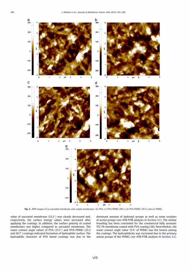
V/5
value of uncoated membrane (53.21) was clearly decreased and,respectively, the surface energy values were increased afterapplying the coatings. In addition, the surface polarity of coatedmembranes was higher compared to uncoated membrane. Thewater contact angle values of PVA (21.51) and PVA–PHMG (25.2and 20.71) coatings indicated formation of hydrophilic surface. Thehydrophilic character of PVA based coatings was due to the
dominant amount of hydroxyl groups as well as some residuesof acetyl groups (see ATR-FTIR analysis in Section 3.1). The similarfounding has been concluded for the commercial fully aromaticTFC PA membrane coated with PVA coating [38]. Nevertheless, thewater contact angle value 15.91 of PHMG was the lowest amongthe coatings. The hydrophilicity was increased due to the primaryamine groups of the PHMG (see ATR-FTIR analysis in Section 3.1).
Fig. 3. AFM images of (a) uncoated membrane and coated membranes: (b) PVA, (c) PVA–PHMG (99:1) (d) PVA–PHMG (95:5) and (e) PHMG.
J. Nikkola et al. / Journal of Membrane Science 444 (2013) 192–200196

V/6 V/7
The diffusion inhibition zone (DIZ) test was conducted tofurther investigate the antimicrobial activity of the membranespecimens. An inhibition circle should form around a specimen,indicating antimicrobial activity and in addition, the leachingeffect of the antimicrobial substance. Fig. 7 presents DIZ testresults for Gram-negative E. coli bacteria and for Gram-positiveB. subtilis bacteria. As expected, uncoated and PVA coated mem-branes did not show the formation of the inhibition circle towardE. coli and B. subtilis, indicating no observation of antimicrobialeffect. The CFU results suggested that antimicrobial activity isobtained using PHMG. According to these results, the antimicro-bial activity was more effective when the PHMG content wasincreased. However, PVA–PHMG coated membranes did not showthe inhibition circle against the bacteria. Nevertheless, the resultsshowed evidently that the pure PHMG coating formed the inhibi-tion circle toward both of E. coli and B. subtilis bacteria, indicatingthe antimicrobial activity. In general, PHMG is known to haveantimicrobial performance, as indicated in the literature [39,40].The formation of strong inhibition zone may also indicate leachingof the PHMG polymer. Therefore, the lack of inhibition circle mightbe explained in the case of PVA–PHMG coatings. In fact, the
decrease in the attachment of bacteria was obtained by addinglow amount of PHMG in PVA coating. In addition, the FTIR spectrarevealed only low intensity peaks assigned for PHMG (Section 3.1).Furthermore, the SEM and the AFM analysis as well as the contactangle measurements suggested that PHMG had minor effect onthe PVA coating morphology, surface texture and hydrophilicity(Sections 3.2–3.4). In that respect, PHMG might be somehowconsolidated into the PVA coating matrix. This could explain thestability of the PVA–PHMG coating, allowing PHMG to be activeagainst bacteria. In particular, our aim was to prevent biofilmformation by developing bacteria repellent anti-adhesion surfacewith a contact killing antimicrobial property, without leaching ofthe antimicrobial agent.
3.7. RO performance
The data obtained from the water flux (Jv) and the salt rejection(R) measurements was used to calculate water (A) and solute (B)permeability. These were used to analyse the effect of coatings onthe membrane separation performance. Water permeability (A)was calculated using the equation A¼(Jv�ΔP)/(ΔP−Δπ) [41].
Fig. 7. Gram negative E. coli DIZ photos of the (a) uncoated and coated membranes: (c) PVA, (e) PVA–PHMG (95:5), (f,g) PHMG. Respectively, gram positive B. subtilis DIZphotos of the (b) uncoated and coated membranes: (d) PVA, (f) PVA–PHMG (95:5) and (h) PHMG.
J. Nikkola et al. / Journal of Membrane Science 444 (2013) 192–200198
3.5. Anti-adhesion performance of membranes
The attachment of model biofilm forming microorganism,P. aeruginosa, was studied in order to demonstrate bacteriarepellence performance of uncoated and coated membranes. Thelower CFU values should indicate stronger bactericidal effects orbacteria repellence (anti-adhesion). Fig. 4 presents the attachmentof P. aeruginosa on uncoated and coated membranes. In general,the CFU test detected lower number of the adhered P. aeruginosaon coated membrane surfaces. In fact, the CFU results revealedthat the attachment of P. aeruginosa were significantly differentbetween the specimens. Therefore, the CFU results are presentedin logarithmic scale for the P. aeruginosa (Fig. 4).
Among the colony counts of the coated membranes, the PHMGcoating showed evidently the lowest number of viable cells ofbacteria. It was also observed that PVA–PHMG coated membranesattracted lower number of the bacteria compared to PVA coatedmembrane. Apparently, the unmodified PVA coating showed onlyminor bacteria repellence effect compared to PHMG modifiedcoatings. Nevertheless, the CFU results evidently showed thatthe PVA coated membrane attracted less bacteria compared tothe uncoated membrane. The effect of the surface properties canbe seen on the attachment of bacteria, because of a clear correla-tion between the increase in hydrophilicity (see Table 2) andcorrespondingly, decrease in the attachment of the bacteria.Furthermore, the lowered surface roughness may have affectedon the attachment of the bacteria. Therefore, PVA coating revealedanti-adhesion and bacteria repellence performance, due to thephysiochemical anti-fouling performance. However, PVA–PHMGand PHMG coatings showed also hydrophilic and smooth surface
roughness. In fact, the attachment of the bacteria decreased by theincrease in the PHMG content in the surface. This suggested thatthe strongest effect on the attachment of bacteria was obtained bycombining the antimicrobial activity with the physiochemicalanti-adhesion surface properties.
3.6. Antimicrobial performance of membranes
The membrane antimicrobial performance was studied bydetermining the number of the viable model bacteria, E. coli andB. subtilis, found on uncoated and coated membrane specimens.Figs. 5 and 6 present the CFU results of E. coli and B. subtilis,respectively. In Fig. 5, the number of E. coli cells of coatedmembranes was lower compared to the uncoated membrane. Inaddition, CFU test results of B. subtilis indicated similar behaviour,although the differences were not as significant. Nevertheless, thetrend of CFU changes was consisted between the specimens.In addition, these CFU results showed similar behaviour of themembrane specimens compared to the study of P. aeruginosa.PHMG coating showed repeatedly the lowest number of viablecells of the bacteria, among the coated membranes. It wassimilarly observed that PVA–PHMG coated membranes attractedlower number of the both bacteria compared to PVA coatedmembrane. The results indicated that PHMG was somewhat moreefficient against the Gram-negative E. coli. Apparently, the unmo-dified PVA coating showed only minor repellence effect on thesebacteria compared to PHMG modified coatings. However, the CFUresults showed that the PVA coated membrane attracted lessbacteria to some extent, in comparison to the uncoated mem-brane, indicating enhanced anti-adhesion performance.
Table 2Summary of the results on water contact angle, surface energies and RRMS
roughness.
Membrane Watercontactangle [o]
Surface energy RoughnessRRMS [nm]
Total[mN/m]
Polar[mN/m]
Dispersive[mN/m]
Uncoated 53.279.2 54.6 11.3 43.3 67.873.3PVA 21.571.9 60.2 20.7 39.5 42.575.9PVA–PHMG(99:1)
25.272.8 59.4 18.7 40.7 54.675.6
PVA–PHMG(95:5)
20.772.4 60.2 21.9 38.3 57.676.2
PHMG 15.971.1 64.9 26.0 38.9 53.472.2
Uncoated PVA PVA-PHMG
(99:1)PVA-PHMG
(95:5)PHMG
0
1
2
3
4
5
6
7
8
Atta
chm
ent o
f P.a
erug
inos
a(L
og C
FU c
m-2
)
Fig. 4. Attachment of Pseudomonas aeruginosa on uncoated and coated membranes.
Uncoated PVA PVA-PHMG(99:1)
PVA-PHMG (95:5)
PHMG0
5000000
10000000
15000000
20000000
25000000
30000000
35000000
40000000
E. c
oli (
CFU
ml-1
)
Fig. 5. CFU results of Escherichia coli on uncoated and coated membranes.
Uncoated PVA PVA-PHMG
(99:1)PVA-PHMG
(95:5)PHMG
0
1000000
2000000
3000000
4000000
5000000
B. s
ubtil
is (
CFU
ml-1
)
Fig. 6. CFU results of Bacillus subtilis on uncoated and coated membranes.
J. Nikkola et al. / Journal of Membrane Science 444 (2013) 192–200 197
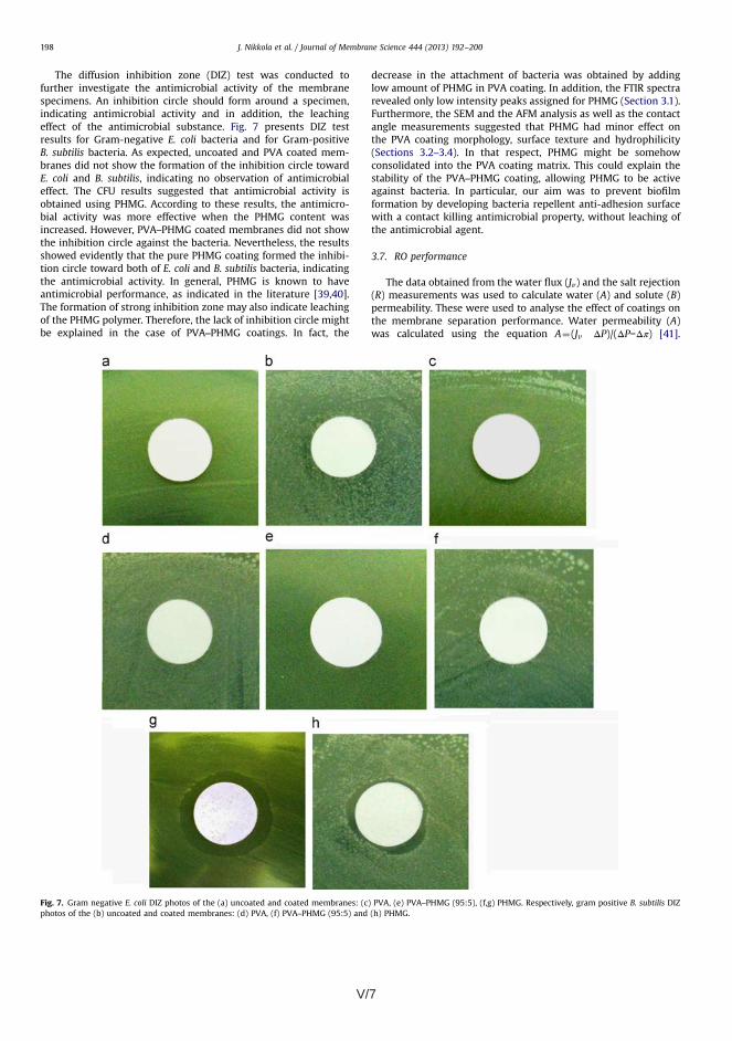
V/7
The diffusion inhibition zone (DIZ) test was conducted tofurther investigate the antimicrobial activity of the membranespecimens. An inhibition circle should form around a specimen,indicating antimicrobial activity and in addition, the leachingeffect of the antimicrobial substance. Fig. 7 presents DIZ testresults for Gram-negative E. coli bacteria and for Gram-positiveB. subtilis bacteria. As expected, uncoated and PVA coated mem-branes did not show the formation of the inhibition circle towardE. coli and B. subtilis, indicating no observation of antimicrobialeffect. The CFU results suggested that antimicrobial activity isobtained using PHMG. According to these results, the antimicro-bial activity was more effective when the PHMG content wasincreased. However, PVA–PHMG coated membranes did not showthe inhibition circle against the bacteria. Nevertheless, the resultsshowed evidently that the pure PHMG coating formed the inhibi-tion circle toward both of E. coli and B. subtilis bacteria, indicatingthe antimicrobial activity. In general, PHMG is known to haveantimicrobial performance, as indicated in the literature [39,40].The formation of strong inhibition zone may also indicate leachingof the PHMG polymer. Therefore, the lack of inhibition circle mightbe explained in the case of PVA–PHMG coatings. In fact, the
decrease in the attachment of bacteria was obtained by addinglow amount of PHMG in PVA coating. In addition, the FTIR spectrarevealed only low intensity peaks assigned for PHMG (Section 3.1).Furthermore, the SEM and the AFM analysis as well as the contactangle measurements suggested that PHMG had minor effect onthe PVA coating morphology, surface texture and hydrophilicity(Sections 3.2–3.4). In that respect, PHMG might be somehowconsolidated into the PVA coating matrix. This could explain thestability of the PVA–PHMG coating, allowing PHMG to be activeagainst bacteria. In particular, our aim was to prevent biofilmformation by developing bacteria repellent anti-adhesion surfacewith a contact killing antimicrobial property, without leaching ofthe antimicrobial agent.
3.7. RO performance
The data obtained from the water flux (Jv) and the salt rejection(R) measurements was used to calculate water (A) and solute (B)permeability. These were used to analyse the effect of coatings onthe membrane separation performance. Water permeability (A)was calculated using the equation A¼(Jv�ΔP)/(ΔP−Δπ) [41].
Fig. 7. Gram negative E. coli DIZ photos of the (a) uncoated and coated membranes: (c) PVA, (e) PVA–PHMG (95:5), (f,g) PHMG. Respectively, gram positive B. subtilis DIZphotos of the (b) uncoated and coated membranes: (d) PVA, (f) PVA–PHMG (95:5) and (h) PHMG.
J. Nikkola et al. / Journal of Membrane Science 444 (2013) 192–200198

V/8 V/9
[22] M. Herzberg, M. Elimelech, Biofouling of reverse osmosis membranes: role ofbiofilm-enhanced osmotic pressure, J. Membr. Sci. 295 (2007) 11–20.
[23] S.B. Sadr Ghayeni, P.J. Beatson, R.P. Schneider, A.G. Fane, Adhesion of wastewater bacteria to reverse osmosis membranes, J. Membr. Sci. 138 (1998)29–42.
[24] M. Klausen, A. Heydorn, P. Ragas, L. Lambertsen, A. Aaes-Jørgensen, S. Molin,T. Tolker-Nielsen, Biofilm formation by Pseudomonas aeruginosa wild type,flagella and type IV pili mutants, Mol. Microbiol. 48 (6) (2003) 1511–1524.
[25] H.-C. Flemming, J. Wingender, The biofilm matrix, Nat. Rev. Microbiol. 8 (2010)623–633.
[26] D1141-98 Standard Practise for the Preparation of Substitute Ocean Water,(2008).
[27] M. Schaechter, Escherichia coli, in: M. Schaechter (Ed.), Encyclopedia ofMicrobiology, third ed., Elsevier Inc., 2009, pp. 125–132.
[28] P.J. Piggot, Bacillus subtilis, in: M. Schaechter (Ed.), Encyclopedia of Micro-biology, third ed., Elsevier Inc., 2009, pp. 45–56.
[29] Clinical Laboratory Standards Institute, Methods for Dilution AntimicrobialSusceptibility Tests for Bacteria that Grow Aerobically, ninth ed. CLSI docu-ment M07-A9 vol. 32 no. 2, Clinical Laboratory Standards Institute, Wayne, PA,2012.
[30] Clinical Laboratory Standards Institute, Performance Standards for Antimicro-bial Disk Susceptibility Tests; Approved standard, ninth ed., CLSI documentM2-A9. 26:1, Clinical Laboratory Standards Institute, Wayne, PA, 2006.
[31] Y.-N. Wang, C.Y. Tang, Protein fouling of nanofiltration, reverse osmosis, andultrafiltration membranes—the role of hydrodynamic conditions, solutionchemistry, and membrane properties, J. Membr. Sci. 376 (2011) 275–282.
[32] R.M. Silverstein, F.X. Webster, Spectrometric Identification of Organic Com-pounds, sixth ed., John Wiley & Sons, Inc., New York, 1997.
[33] N.B. Colthup, L.H. Daly, S.E. Wiberley, Introduction to Infrared and RamanSpectroscopy, Academic Press Inc., New York, 1975.
[34] H.S. Mansur, C.M. Sadahira, A.N. Souza, A.A.P. Mansur, FTIR spectroscopycharacterization of poly (vinyl alcohol) hydrogel with different hydrolysisdegree and chemically crosslinked with glutaraldehyde, Mater. Sci. Eng., C 28(2008) 539–548.
[35] H. Hachisuka, K. Ikeda, Composite Reverse Osmosis Membrane Having aSeparation layer with Polyvinyl Alcohol Coating and Method of ReverseOsmosis Treatment of Water Using the Same. (2001) US Patent 6177011 B1.
[36] I.C. Kim, K.H. Lee, Dyeing process wastewater treatment using fouling resistantnanofiltration and reverse osmosis membranes, Desalination 192 (2006)246–251.
[37] C.Y. Tang, Y.-N. Kwon, J.O. Leckie, Effect of membrane chemistry and coatinglayer on physiochemical properties of thin film composite polyamide RO andNF membranes II. Membrane physiochemical properties and their dependenceon polyamide and coating layers, Desalination 242 (2009) 168–182.
[38] K.C. Khulbe, C.Y. Feng, T. Matsuura, Synthetic polymeric membranes—char-acterisation by atomic force microscopy, Springer-Verlag, Berlin Heidelberg157–167.
[39] O.J. Schmidt, A. Schmidt, D. Toptchiev, Biocidal Polymers Based on GuanidineSalts. (2006) US Patent 7001606.
[40] Z.X. Zhou, D.F. Wei, Y. Guan, A.N. Zheng, J.J. Zhong, Damage of Escherichia colimembrane by bactericidal agent polyhexamethylene guanidine hydrochlor-ide: micrographic evidences, J. Appl. Microbiol. 108 (2010) 898–907.
[41] A.G. Fane, C.Y. Tang, R. Wang, Membrane Technology for Water: Microfiltra-tion, Ultrafiltration, Nanofiltration and Reverse Osmosis, Elsevier, USA, 2010,chapter 91.
[42] J.S. Louie, I. Pinnau, I. Ciobanu, K.P. Ishida, A. Ng, M. Reinhard, Effects ofpolyether–polyamide block copolymer coating on performance and fouling ofreverse osmosis membranes, J. Membr. Sci. 280 (2006) 762–770.
J. Nikkola et al. / Journal of Membrane Science 444 (2013) 192–200200
Solute permeability (B) was correspondingly calculated accordingto the equation B¼(Jv�ΔP)� (1/R−1) [41]. Table 3 summarises thevalues of the water permeability (A), the salt (NaCl) rejection (R)and the salt (NaCl) permeability of uncoated and coated mem-branes. The coating layers reduced the permeability propertiescompared to uncoated membrane. Among the coated membranes,the PVA coating reduced the water permeability approximately15%, and correspondingly the salt rejection showed minorincrease. However, PVA coating decreased the NaCl permeabilityalmost 55%. In comparison, PVA–PHMG coatings led to 45% and58% decline in the water permeability. Their salt rejection waswithin the error bars in comparison to uncoated or PVA coatedmembrane. In addition, PHMG content did not have much effecton NaCl permeability of PVA coating. The pure PHMG coatedmembrane showed 78% decline in water permeability. In fact,membranes with higher PHMG percentage tended to decreasewater permeability. Furthermore, the pure PHMG coating signifi-cantly decreased the salt rejection and, respectively, slightlyincreased NaCl permeability. According to the calculation of NaClpermeability, the lower salt rejection could be contributed to thelower water flux (low water permeability or low pressure). Itexplains the decrease in salt permeability of the membrane withlower water permeability. Furthermore, some other investigationshave typically shown 50–80 % decrease in the water and saltpermeability of coated membranes [11,42]. Therefore, in condi-tions where higher pressure is applied or the membrane withreasonable permeability combination, the membrane is preferredin view of the better anti-fouling performance.
4. Conclusions
Polymeric thin coatings were successfully applied on TFC PAmembrane. The coating thicknesses varied from 100 to 250 nm. Allthe coatings increased the hydrophilicity and decreased the sur-face roughness compared to uncoated membrane. In addition, allthe coated membranes decreased the attachment of bacteria onthe surface. PVA coating showed anti-adhesion performance,showing decrease in the attachment of all the model bacteria.Coated membranes with higher PHMG percentage tended to havehigher bacteria repellent and antimicrobial performance. CFU andDIZ results proved the antimicrobial performance of PHMG. There-fore, an optimal anti-fouling surface could be obtained applying acoating, which consists of anti-adhesion and antimicrobial perfor-mance. However, further optimisation of PVA–PHMG compositionis needed in order to maintain the anti-fouling performance,without sacrificing the RO performance. In addition, the further
studies will include long-term fouling studies of PVA–PHMGcoated RO membranes.
Acknowledgements
The authors acknowledge Tekes (the Finnish Funding Agencyfor Technology and Innovation) and VTT Technical Research Centreof Finland due to the financial support of project. Skilful technicalassistances of Niina Torttila, Sini Eskonniemi and Marjo Ketonenare acknowledged in the microbiological part, the contact anglemeasurements and SEM imaging.
References
[1] H.-C. Hemming, Reverse osmosis membrane biofouling, Exp. Therm Fluid Sci.14 (4) (1997) 382–391.
[2] T. Nguyen, F.A. Roddick, L. Fan, Biofouling of water treatment membranes: areview of the underlying causes, monitoring techniques and control measures,Membranes 2 (2012) 804–840.
[3] V. Chen, J. Mansouri, T. Charlton, Biofouling in membrane systems, in: K.-V. Peinemann, S.P. Nunes (Eds.), Membranes for Water Treatment, vol. 4,Wiley-VCH, Weinheim, 2010, pp. 25–48.
[4] R. Field, Fundamentals of fouling, in: K.-V. Peinemann, S.P. Nunes (Eds.),Membranes for Water Treatment, vol. 4, Wiley-VCH, Weinheim, 2010,pp. 1–23.
[5] D. Rana, T. Matsuura, Surface modifications for antifouling membranes, Chem.Rev. 110 (2010) 2448–2471.
[6] K. Bazaka, R.J. Crawford, E.P. Ivanova, Review: do bacteria differentiatebetween degrees of nanoscale surface roughness? Biotechnol. J. 6 (2011)1103–1114.
[7] S.D. Puckett, E. Taylor, T. Raimondo, T.J. Webster, The relationship between thenanostructure of titanium surfaces and bacterial attachment, Biomaterials 31(2010) 706–713.
[8] M. Ulbricht, Advanced functional polymer membranes, Polymer 47 (2006)2217–2262.
[9] C.Y. Tang, Y.-N. Kwon, J.O. Leckie, Effect of membrane chemistry and coatinglayer on physiochemical properties of thin film composite polyamide RO andNF membranes: I. FTIR and XPS characterization of polyamide and coatinglayer chemistry, Desalination 242 (2009) 149–167.
[10] R. Bernstein, S. Belfer, V. Freger, Bacterial attachment to RO membranessurface-modified by concentration-polarization-enhanced graft polymeriza-tion, Environ. Sci. Technol. 45 (2011) 5973–5980.
[11] A.C. Sagle, E.M. VanWagner, H. Ju, B.D. McCloskey, B.D. Freeman, M.M. Sharma,PEG-coated reverse osmosis membranes: desalination properties and foulingresistance, J. Membr. Sci. 340 (2009) 92–108.
[12] E.M. Van Wagner, A.C. Sagle, M.M. Sharma, Y.-H. La, B.D. Freeman, Surfacemodification of commercial polyamide desalination membranes using poly(ethylene glycol) diglycidyl ether to enhance membrane fouling resistance,J. Membr. Sci. 367 (2011) 273–287.
[13] S. Belfer, Y. Purinson, R. Fainshtein, Y. Radchenko, O. Kedem, Surface modifica-tion of commercial composite polyamide reverse osmosis membranes,J. Membr. Sci. 139 (1998) 175–181.
[14] S. Yu, Z. Lü, Z. Chen, X. Liu, M. Liu, C. Gao, Surface modification of thin-filmcomposite polyamide reverse osmosis membranes by coating N-isopropyla-crylamide-co-acrylic acid copolymers for improved membrane properties,J. Membr. Sci. 371 (2011) 293–306.
[15] J. Gilron, S. Belfer, P. Väisänen, M. Nyström, Effects of surface modification onantifouling and performance properties of reverse osmosis membranes,Desalination 140 (2001) 167–179.
[16] I. Sawada, R. Fachrul, T. Ito, Y. Ohmukai, T. Maruyama, H. Matsuyama,Development of a hydrophilic polymer membrane containing silver nanopar-ticles with both organic antifouling and antibacterial properties, J. Membr. Sci.387–388 (2012) 1–6.
[17] S. Balta, A. Sotto, P. Luisa, L. Benea, B. Van der Bruggena, J. Kim, A. New,Outlook on membrane enhancement with nanoparticles: the alternative ofZnO, J. Membr. Sci. 389 (2012) 155–161.
[18] F. Diagne, R. Malaisamy, V. Boddie, R.D. Holbrook, B. Eribo, K.L. Jones,Polyelectrolyte and silver nanoparticle modification of microfiltration mem-branes to mitigate organic and bacterial fouling, Environ. Sci. Technol. 3 (46)(2012) 4025–4033.
[19] A. Zago, S. Chugani, Pseudomonas, in: M. Schaechter (Ed.), Encyclopedia ofMicrobiology, third ed.,Elsevier Inc., 2009, pp. 245–260.
[20] B. Bolto, T. Tran, M. Hoang, Z. Xie, Crosslinked poly(vinyl alcohol) membranes,Progr. Polym. Sci 34 (2009) 969–981.
[21] K. Grundke, Characterization of polymer surfaces by wetting and electro-kinetic measurements—contact angle, interfacial tension, zeta potential, in:M. Stamn (Ed.), Polymer Surfaces and Interfaces—Characterization, Modifica-tion and Applications, first ed.,Springer-Verlag, Berlin Heidelberg, 2008,pp. 103–136.
Table 3Water permeability coefficient (A), salt rejection (R) and salt permeability coeffi-cient (B) of uncoated and coated membranes.
Membrane Water permeabilitycoefficient (A)[L/m2/h/bar]a
Salt rejection(R) [%]a
Salt permeabilitycoefficient (B)[L/m2/h]a
Uncoatedmembrane
4.3570.48 97.271.2 3.4771.87
PVA 3.7170.31 98.570.6 1.5370.51PVA–PHMG(99:1)
2.3970.60 98.270.6 1.2670.70
PVA–PHMG(95:5)
1.6770.25 95.872.2 2.1771.28
PHMG 0.7670.48 91.670.3 2.3071.29
a Water flux (Jv) and salt rejection (R) of the membranes were evaluated using10 mM NaCl feed solution and applied pressure of 27.6 bar (400 psi) at 23 1C. Theexperimental errors represent the standard deviation of three repeated measure-ments.
J. Nikkola et al. / Journal of Membrane Science 444 (2013) 192–200 199

V/9
[22] M. Herzberg, M. Elimelech, Biofouling of reverse osmosis membranes: role ofbiofilm-enhanced osmotic pressure, J. Membr. Sci. 295 (2007) 11–20.
[23] S.B. Sadr Ghayeni, P.J. Beatson, R.P. Schneider, A.G. Fane, Adhesion of wastewater bacteria to reverse osmosis membranes, J. Membr. Sci. 138 (1998)29–42.
[24] M. Klausen, A. Heydorn, P. Ragas, L. Lambertsen, A. Aaes-Jørgensen, S. Molin,T. Tolker-Nielsen, Biofilm formation by Pseudomonas aeruginosa wild type,flagella and type IV pili mutants, Mol. Microbiol. 48 (6) (2003) 1511–1524.
[25] H.-C. Flemming, J. Wingender, The biofilm matrix, Nat. Rev. Microbiol. 8 (2010)623–633.
[26] D1141-98 Standard Practise for the Preparation of Substitute Ocean Water,(2008).
[27] M. Schaechter, Escherichia coli, in: M. Schaechter (Ed.), Encyclopedia ofMicrobiology, third ed., Elsevier Inc., 2009, pp. 125–132.
[28] P.J. Piggot, Bacillus subtilis, in: M. Schaechter (Ed.), Encyclopedia of Micro-biology, third ed., Elsevier Inc., 2009, pp. 45–56.
[29] Clinical Laboratory Standards Institute, Methods for Dilution AntimicrobialSusceptibility Tests for Bacteria that Grow Aerobically, ninth ed. CLSI docu-ment M07-A9 vol. 32 no. 2, Clinical Laboratory Standards Institute, Wayne, PA,2012.
[30] Clinical Laboratory Standards Institute, Performance Standards for Antimicro-bial Disk Susceptibility Tests; Approved standard, ninth ed., CLSI documentM2-A9. 26:1, Clinical Laboratory Standards Institute, Wayne, PA, 2006.
[31] Y.-N. Wang, C.Y. Tang, Protein fouling of nanofiltration, reverse osmosis, andultrafiltration membranes—the role of hydrodynamic conditions, solutionchemistry, and membrane properties, J. Membr. Sci. 376 (2011) 275–282.
[32] R.M. Silverstein, F.X. Webster, Spectrometric Identification of Organic Com-pounds, sixth ed., John Wiley & Sons, Inc., New York, 1997.
[33] N.B. Colthup, L.H. Daly, S.E. Wiberley, Introduction to Infrared and RamanSpectroscopy, Academic Press Inc., New York, 1975.
[34] H.S. Mansur, C.M. Sadahira, A.N. Souza, A.A.P. Mansur, FTIR spectroscopycharacterization of poly (vinyl alcohol) hydrogel with different hydrolysisdegree and chemically crosslinked with glutaraldehyde, Mater. Sci. Eng., C 28(2008) 539–548.
[35] H. Hachisuka, K. Ikeda, Composite Reverse Osmosis Membrane Having aSeparation layer with Polyvinyl Alcohol Coating and Method of ReverseOsmosis Treatment of Water Using the Same. (2001) US Patent 6177011 B1.
[36] I.C. Kim, K.H. Lee, Dyeing process wastewater treatment using fouling resistantnanofiltration and reverse osmosis membranes, Desalination 192 (2006)246–251.
[37] C.Y. Tang, Y.-N. Kwon, J.O. Leckie, Effect of membrane chemistry and coatinglayer on physiochemical properties of thin film composite polyamide RO andNF membranes II. Membrane physiochemical properties and their dependenceon polyamide and coating layers, Desalination 242 (2009) 168–182.
[38] K.C. Khulbe, C.Y. Feng, T. Matsuura, Synthetic polymeric membranes—char-acterisation by atomic force microscopy, Springer-Verlag, Berlin Heidelberg157–167.
[39] O.J. Schmidt, A. Schmidt, D. Toptchiev, Biocidal Polymers Based on GuanidineSalts. (2006) US Patent 7001606.
[40] Z.X. Zhou, D.F. Wei, Y. Guan, A.N. Zheng, J.J. Zhong, Damage of Escherichia colimembrane by bactericidal agent polyhexamethylene guanidine hydrochlor-ide: micrographic evidences, J. Appl. Microbiol. 108 (2010) 898–907.
[41] A.G. Fane, C.Y. Tang, R. Wang, Membrane Technology for Water: Microfiltra-tion, Ultrafiltration, Nanofiltration and Reverse Osmosis, Elsevier, USA, 2010,chapter 91.
[42] J.S. Louie, I. Pinnau, I. Ciobanu, K.P. Ishida, A. Ng, M. Reinhard, Effects ofpolyether–polyamide block copolymer coating on performance and fouling ofreverse osmosis membranes, J. Membr. Sci. 280 (2006) 762–770.
J. Nikkola et al. / Journal of Membrane Science 444 (2013) 192–200200

PUBLICATION P6
Surface modification of thin film composite polyamide
membrane using atomic layer deposition method
In: Journal of Membrane Science (450) 2014, pp. 174–180.
Copyright 2013 Elsevier B.V.Reprinted with permission from the publisher.

VI/1

VI/1
Surface modification of thin film composite polyamide membraneusing atomic layer deposition method
Juha Nikkola a,n, Jenni Sievänen b, Mari Raulio b, Jing Wei c,d, Jyrki Vuorinen e,Chuyang Y. Tang c,d
a VTT Technical Research Centre of Finland, PO Box 1300, 33101 Tampere, Finlandb VTT Technical Research Centre of Finland, PO Box 1000, 02044 Espoo, Finlandc School of Civil and Environmental Engineering, Nanyang Technological University, Singapore 639798, Singapored Singapore Membrane Technology Centre, Nanyang Technological University, Singapore 639798, Singaporee Department of Materials Science, Tampere University of Technology, PO Box 589, 33101 Tampere, Finland
a r t i c l e i n f o
Article history:Received 14 June 2013Received in revised form30 August 2013Accepted 4 September 2013Available online 10 September 2013
Keywords:Thin-film-composite (TFC) polyamide (PA)Reverse osmosis membraneInorganic surface modificationAtomic layer deposition (ALD)Aluminium oxide (Al2O3)
a b s t r a c t
We present surface modification of thin-film-composite (TFC) polyamide (PA) reverse osmosis (RO)membrane by atomic layer deposition (ALD) process using trimethylaluminium (AlMe3). The aim of theinorganic ALD coating is to improve the anti-fouling performance of TFC PA membranes. The ALDprocessing parameters were systematically studied because of the lack of previous investigations of theALD coated RO membranes. Two different processing temperatures (70 1C and 100 1C) and three differentALD cycles (10, 50 and 100) were used to deposit the Al2O3 ALD coatings on TFC PA membranes. The ALDprocess parameters affected on the hydrophilicity and the surface polarity as well as on the surfaceroughness of the coated membranes. The bacteria attachment test results indicated that the lowestnumber of Pseudomonas aeruginosa cells was adhered on the most hydrophilic and polar surface, amongthe ALD coated membranes. RO tests showed the effect of ALD coating on the water and salt permeabilityas well as on the salt rejection of the membranes.
& 2013 Elsevier B.V. All rights reserved.
1. Introduction
Membrane fouling, such as scaling, colloidal fouling (inorganicand organic) and biofouling, has remained a critical issue in thereverse osmosis (RO) process [1]. For example, thin-film-composite (TFC) polyamide (PA) membranes have shown to bevulnerable to fouling in the RO process. Several surface propertiesof TFC PA membranes, including hydrophilicity and low surfaceroughness, have shown to play a key role in reducing themembrane fouling [2]. Researchers have developed variousapproaches to modify the surfaces of TFC PA membranes tointroduce anti-adhesion and antimicrobial surface [3]. Indeed,many commercial “low fouling” TFC PA membranes contain anadditional polymeric coating layer to enhance their anti-foulingperformance [4]. Compared to the vast literature on organic/polymeric surface coatings or modifications, there are few studieson inorganic coatings as a surface modification of RO membranes[5], despite their great potential to increase the mechanical andthe chemical stability as well as to decrease the fouling tendency.
Atomic layer deposition (ALD) technology has been usedalmost four decades for manufacturing inorganic coating layers,such as oxides, nitrides and sulphides, with thickness down to thenanometre range [6]. Manufacturing of Al2O3 thin films using theself-terminating reaction of trimethylaluminium (AlMe3, Me¼CH),with water or ozone, is considered as an ideal example of the ALDprocess [7]. Recent advancement in ALD technology has increasedits potential to produce functional thin films on flexible andtemperature-sensitive polymeric materials [8,9]. The technologyhas also been applied to coat various fibrous polymers [10–13].
In recent years, a few research groups have investigated ALDtechnology as surface modification of porous microfiltration andultrafiltration, including both polymeric and ceramic membranes[14–18]. These studies suggested that ALD processing parameters,such as temperature and number of ALD cycles, have clear impacton membrane performance. For example, they have shown aneffect on the pore size of membrane, which have affected on solutepermeability and rejection properties [16,17]. Furthermore, hydro-philic and smooth polymeric membranes have been obtainedusing AlMe3 based ALD technology [15], which increases itspotentiality to create low-fouling membrane surface. However,hydrophilicity and low surface roughness have been typicallyobtained using a relatively thick ALD coating, such as 300–500ALD cycles [14,16]. In addition, the change in the ALD processing
Contents lists available at ScienceDirect
journal homepage: www.elsevier.com/locate/memsci
Journal of Membrane Science
0376-7388/$ - see front matter & 2013 Elsevier B.V. All rights reserved.http://dx.doi.org/10.1016/j.memsci.2013.09.005
n Corresponding author. Tel.: þ358 405358169; fax: þ358 207223498.E-mail address: [email protected] (J. Nikkola).
Journal of Membrane Science 450 (2014) 174–180

VI/2 VI/3
(3000 rpm, 10 min) and washed with phosphate bufferedsaline (PBS) (10 mM). The cell density was approximately1�108 CFU mL�1 determined by plate count on Trypticase soyagar (TSA) (37 1C, 1 d). The exposure of membranes was conductedin a rotary shaker (75 rpm) at room temperature for 1 d. Thenumber of adhered cells on the membranes was determinedafter swabbing by plate count on TSA (37 1C, 1 d). Results arepresented as colony forming units per membrane area(CFU cm�2). Three replicate membrane samples were examinedfor each membrane type.
2.5. Water permeability and salt rejection
Uncoated and coated membranes were tested in a lab-scalecrossflow filtration setup to evaluate their water permeability andNaCl rejection according to Wang et al. [27]. Membranes weretested at a feed pressure of 27.6 bar (400 psi) using a feed watercontaining 10 mM NaCl. The temperature of feed water wasmaintained at 23 1C. Water flux of the membranes was determinedby the gravimetric method. Membrane NaCl rejection (R) wasdetermined by
R¼ Cf�Cp
Cp100%
where Cf and Cp are the concentrations (via conductivity measure-ments) of feed and permeate solutions, respectively.
Water permeability (A) was calculated using the equationA¼(Jv�ΔP)/(ΔP�Δπ) [28]. Solute permeability (B) was corre-spondingly calculated according to the equation B¼(Jv�ΔP)�(1/R�1) [28].
3. Results and discussion
3.1. ATR-FTIR measurements
Fig. 1 presents the FTIR spectra of uncoated and ALD coatedmembranes in the range of 2000–500 cm�1, and Table 2 sum-marises the corresponding peak assignments. The uncoated mem-brane showed typical FTIR spectra of fully aromatic PA membranesformed from m-phenylenediamine and trimesoyl chloride on top ofa polysulfone (PSf) support layer [29]. The peak at 1660 cm�1 wasassigned to the C¼O stretching (amide I band), and the peak at1540 cm�1 was assigned to the N–H bending (amide II band),which are known to be typical for a secondary amide group [30,31].The latter peak is due to the interaction between N–H bending and
C–N stretching of the –CO–N–H group [30,31]. The peak at1610 cm�1 was assigned as C¼C stretching of the aromatic ring.The characteristic peaks for the PSf support layer were detected at1324 cm�1 (SO2 asymmetric stretching), 1244 cm�1 (C–O–Cstretching) and 1180 cm�1 (SO2 symmetric stretching) [29].
The FTIR spectra of the ALD coated membranes showed most ofthe significant peaks assigned for PA (1660, 1610, and 1540 cm�1)and PSf (1324, 1244 and 1180 cm�1), although the intensities ofthese peaks were reduced compared to the uncoated membrane.The decrease of the peak intensities was more prominent forthicker coating layers, which can be explained by the dilutioneffect due to the presence of the coating material. In addition, thedecrease in the peak intensity at 1660 cm�1 and 1540 cm�1 mightbe partially attributed to the reaction of AlMe3 precursors withC¼O groups of PA (to produce C–O–Al bonds) [11,12] and N–Hgroups (to form Al–-N bonds) [11,12], respectively. In addition, thecoated membranes showed the appearance of a new low intensitypeak at 1150 cm�1, which may originate from residues ofunreacted Al–CH3 group of the AlMe3 precursor [11,12].
3.2. SEM characterisation
The SEM characterisation was performed to determine thesurface morphology of the ALD coated membranes. Fig. 2 presentsthe SEM images of uncoated and coated membranes. SEM imagesof the ALD coated membranes (Fig. 2b–g) indicated some changesin the surface morphology compared to virgin membrane. Themembranes coated at 100 1C looked generally tighter compared tothose coated at 70 1C. Moreover, a tightening of the ALD coatinglayer can be noticed due to increase in the coating thickness. Thetightening could cause significant hydraulic resistance of thecoating layer and decrease in RO performance.
3.3. AFM characterisation
Fig. 3 presents AFM images of uncoated and ALD coated TFC PAmembranes. The uncoated membrane (Fig. 3a) showed a ridge-and-valley as well as nodular surface texture, which is typical forTFC PA membranes [4,32]. Furthermore, its RMS roughness value(Table 3) was comparable to previous investigations [4].
The AFM images of the coated membranes indicated a particle-like topography of ALD coating (Fig. 3), which is typically obtainedusing low number of ALD cycles [14,33]. Furthermore, the numberof the ALD cycles seemed to have an effect on the surfacetopography, as shown in Fig. 3.
Table 3 summarises the roughness values. The RRMS roughnessvalue of coated membranes reduced significantly after 10 cycles ofALD coating, which may be due to the deposition of a few particleson the surface filling the valley areas. However, increase of thecoating layer thickness significantly increased the RRMS roughnessof the coated membranes. Moreover, ALD coating layer with 100
2000 1800 1600 1400 1200 1000 800 600
*
*
*
*
*
*
*
*
*
*
*
*
*
*
*
*
*
*
Abs
orba
nce
(a.u
.)
c100_t70
c50_t70
c10_t70
Wavenumber (cm-1)
Uncoated
Fig. 1. FTIR spectra of uncoated and ALD coated (at 70 1C) specimens. The mostessential peaks are marked with *.
Table 2Summary of the peak assignments.
Origin of thepeaks
Wavenumber(cm�1)
Peak assignment
Polysulfone 1324 SO2 asymmetric stretching [29–31]1244 C–O–C stretching of aryl group [29–31]1180 SO2 symmetric stretching [29–31]
Aromaticpolyamide
1660 C¼O stretching (amide I band) [29–31]1610 C¼C stretching of the aromatic ring
[29–31]
ALD coating 1540 N–H bending (amide II band) [29–31]1150 Al–CH3 [11,12]
J. Nikkola et al. / Journal of Membrane Science 450 (2014) 174–180176
temperature has affected on reactivity of AlMe3 [11]. For example,the most hydrophilic membrane surface has been obtained at150 1C [14]. The increase of ALD coating thickness and temperaturemay negatively affect the RO membrane performance by tighten-ing the rejection layer of temperature-sensitive polymeric mem-brane. Therefore, further understanding of the ALD process isneeded in order to overcome the current drawbacks and todevelop new low-fouling RO membrane using the ALD technology.To the best knowledge of the authors, the ALD method has notbeen applied for modifying RO membranes, and therefore sys-tematic study is needed to introduce ALD technology to the ROmembranes.
Our aim was to investigate the surface modification of TFC PAmembrane using the AlMe3 based ALD process. Two differentprocessing temperatures (70 1C and 100 1C) and three differentnumber of ALD cycles (10, 50 and 100) were used to apply the ALDcoatings on TFC PA membranes. The ALD process parameters wereshown to have effect on the surface roughness as well as on thehydrophilicity and surface polarity of TFC PA membranes. Thebacterial attachment test simulated the effect of ALD coating onthe biofouling tendency. Furthermore, RO tests showed their effecton the water permeability and salt rejection.
2. Experimental
2.1. Materials
The commercial TFC PA membrane DOW™ FILMTEC™ LE-400(The Dow Chemical Company, Midland, MI, USA) was used as-received as a substrate for the ALD coatings. Trimethylaluminum(AlMe3) was purchased from Sigma-Aldrich (St. Louis, MO, USA)and it was used as received.
2.2. ALD coatings
The ALD-Al2O3 depositions were carried out in a PicosunSUNALE™ reactor (Picosun, Espoo, Finland) on substrates thatwere 10�10 cm2 in size. AlMe3 and H2O were used as precursors.The ALD process parameters were selected according to ourprevious investigations on low-temperature ALD process fortemperature-sensitive substrates [9,19,20]. Two different proces-sing temperatures (70 1C and 100 1C) and three different ALDcycles (10, 50 and 100) were used to deposit the ALD coatingson the TFC PA membranes. Table 1 summarises the ALD coatedspecimens with their processing parameters. The coated mem-branes are named according to the coating cycles and temperature(e.g., c10_t70 denotes a membrane with 10 coating cycles at 70 1C).
Furthermore, our previous investigations have shown the effectof physical and chemical pre-treatment on the ALD layer growth,which has occurred due to the changes in surface morphology andchemistry of temperature-sensitive substrate [9]. Because RO
membrane is sensitive to the changes in its surface morphology,it was decided to deposit the ALD coatings on virgin TFC PAmembranes without further pre-treatment.
The precursor pulsing sequence was 0.1 s AlMe3 pulse, 10 s N2
purge, 0.1 s H2O, 10 s N2 purge and the number of ALD cycles wasadjusted according to the targeted Al2O3 coating thickness. Thenominal thicknesses of the coating was estimated based on thegrowth rate 0.1 nm/cycle measured from films grown on a siliconwafer with a Nanospec AFT 4150 reflectometer [19,20]. ALD coat-ings have shown a minor variation of the actual film thickness,because of the difference in surface chemistry and roughness ofdifferent polymers, in comparison to a silicon wafer. Although, theaimwas to deposit the ALD film on PA side, the film growth cannotbe totally prevented on reverse side of the membrane.
2.3. Membrane characterisations
ATR-FTIR measurement was carried out to analyse the surfacechemistry of uncoated and coated membranes. Perkin Elmerspectrum BX II FT-IR (Fourier transform IR) system was equippedwith vertical-Attenuated total reflectance (ATR) and KRS-5 (Thal-lium Bromoiodide) crystal. In a typical analysis 50 scans werecollected from 500 to 4000 cm�1 at 4 cm�1 resolution. A back-ground spectrum of pure KRS-5 was collected before running thesamples.
The microscopic imaging of uncoated and coated membraneswas conducted using scanning electron microscope (SEM) JEOLJSM-6360 LV 11 kV on high vacuum mode. All SEM samples weresputter coated with gold before imaging.
The surface topography of uncoated and coated membranesamples were characterised using non-contact mode atomic forcemicroscopy (NC-AFM). The NC-AFM analysis was performed usingPark Systems XE-100 AFM equipment (Suwon, South-Korea), withcantilever 905M-ACTA (AppNano Inc., Santa Clara, CA, USA).Typically, the scan rate was 0.4–0.6 Hz and the measured areawas 5�5 mm2. Six replicate measurements were performed todetermine the root-mean-square roughness value, RRMS.
The contact angle measurements were conducted by usingOptical Tensiometer Theta T200 device (Attension, Biolin Scienti-fic). The measurements were performed in a controlled atmo-sphere (RH 50%, temperature 23 1C) and the results are given as anaverage of five parallel measurements. The water contact anglevalues, expressed as deg, are presented at the time of 30 s from themoment the drop contacts the surface. The surface energy valueswere obtained by measuring the contact angle of three differentprobe liquids, including water (H2O, γ¼72.80 mN/m), di-iodomethane (CH2I2, γ¼50.80 mN/m) and formamide (CH3NO,γ¼58.20 mN/m). The total surface energy values, as summary ofpolar and dispersive surface energies, were determined from themeasured contact angle data using the Fowkes theory [21].
2.4. Bacterial anti-adhesion performance
Biofilm formation was demonstrated by analysing the attach-ment of Pseudomonas aeruginosa on uncoated and coated mem-branes. P. aeruginosa is Gram-negative, aerobic, rod-shapedbacterium, which is widely used as the model microbe for biofilmformation studies [22–25]. Therefore, P. aeruginosa was selected asmodel bacterium in our study to provide comparable data relatedto the attachment of bacteria.
Bacteria attachment test was conducted according to ourprevious studies [3]. The membranes (∅ 4.7 cm) were submergedin bacterial suspension consisting of standard seawater ASTMD1141-98 (2008) [26]. Furthermore, the suspension was inoculatedwith overnight culture of P. aeruginosa (VTT E-96726) cultivatedin 37 1C Trypticase soy broth solution, harvested by centrifugation
Table 1Summary of the ALD coated specimens with their processing parameters.
Sample IDa Numberof cycles
Processing temp. (1C) Nominal coating thicknessb (nm)
c10_t70 10 70 1c50_t70 50 70 5c100_t70 100 70 10c10_t100 10 100 1c50_t100 50 100 5c100_t100 100 100 10
a Al2O3 coating.b Nominal thickness according to the growth rate 0.1 nm/cycle [19,20].
J. Nikkola et al. / Journal of Membrane Science 450 (2014) 174–180 175

VI/3
(3000 rpm, 10 min) and washed with phosphate bufferedsaline (PBS) (10 mM). The cell density was approximately1�108 CFU mL�1 determined by plate count on Trypticase soyagar (TSA) (37 1C, 1 d). The exposure of membranes was conductedin a rotary shaker (75 rpm) at room temperature for 1 d. Thenumber of adhered cells on the membranes was determinedafter swabbing by plate count on TSA (37 1C, 1 d). Results arepresented as colony forming units per membrane area(CFU cm�2). Three replicate membrane samples were examinedfor each membrane type.
2.5. Water permeability and salt rejection
Uncoated and coated membranes were tested in a lab-scalecrossflow filtration setup to evaluate their water permeability andNaCl rejection according to Wang et al. [27]. Membranes weretested at a feed pressure of 27.6 bar (400 psi) using a feed watercontaining 10 mM NaCl. The temperature of feed water wasmaintained at 23 1C. Water flux of the membranes was determinedby the gravimetric method. Membrane NaCl rejection (R) wasdetermined by
R¼ Cf�Cp
Cp100%
where Cf and Cp are the concentrations (via conductivity measure-ments) of feed and permeate solutions, respectively.
Water permeability (A) was calculated using the equationA¼(Jv�ΔP)/(ΔP�Δπ) [28]. Solute permeability (B) was corre-spondingly calculated according to the equation B¼(Jv�ΔP)�(1/R�1) [28].
3. Results and discussion
3.1. ATR-FTIR measurements
Fig. 1 presents the FTIR spectra of uncoated and ALD coatedmembranes in the range of 2000–500 cm�1, and Table 2 sum-marises the corresponding peak assignments. The uncoated mem-brane showed typical FTIR spectra of fully aromatic PA membranesformed from m-phenylenediamine and trimesoyl chloride on top ofa polysulfone (PSf) support layer [29]. The peak at 1660 cm�1 wasassigned to the C¼O stretching (amide I band), and the peak at1540 cm�1 was assigned to the N–H bending (amide II band),which are known to be typical for a secondary amide group [30,31].The latter peak is due to the interaction between N–H bending and
C–N stretching of the –CO–N–H group [30,31]. The peak at1610 cm�1 was assigned as C¼C stretching of the aromatic ring.The characteristic peaks for the PSf support layer were detected at1324 cm�1 (SO2 asymmetric stretching), 1244 cm�1 (C–O–Cstretching) and 1180 cm�1 (SO2 symmetric stretching) [29].
The FTIR spectra of the ALD coated membranes showed most ofthe significant peaks assigned for PA (1660, 1610, and 1540 cm�1)and PSf (1324, 1244 and 1180 cm�1), although the intensities ofthese peaks were reduced compared to the uncoated membrane.The decrease of the peak intensities was more prominent forthicker coating layers, which can be explained by the dilutioneffect due to the presence of the coating material. In addition, thedecrease in the peak intensity at 1660 cm�1 and 1540 cm�1 mightbe partially attributed to the reaction of AlMe3 precursors withC¼O groups of PA (to produce C–O–Al bonds) [11,12] and N–Hgroups (to form Al–-N bonds) [11,12], respectively. In addition, thecoated membranes showed the appearance of a new low intensitypeak at 1150 cm�1, which may originate from residues ofunreacted Al–CH3 group of the AlMe3 precursor [11,12].
3.2. SEM characterisation
The SEM characterisation was performed to determine thesurface morphology of the ALD coated membranes. Fig. 2 presentsthe SEM images of uncoated and coated membranes. SEM imagesof the ALD coated membranes (Fig. 2b–g) indicated some changesin the surface morphology compared to virgin membrane. Themembranes coated at 100 1C looked generally tighter compared tothose coated at 70 1C. Moreover, a tightening of the ALD coatinglayer can be noticed due to increase in the coating thickness. Thetightening could cause significant hydraulic resistance of thecoating layer and decrease in RO performance.
3.3. AFM characterisation
Fig. 3 presents AFM images of uncoated and ALD coated TFC PAmembranes. The uncoated membrane (Fig. 3a) showed a ridge-and-valley as well as nodular surface texture, which is typical forTFC PA membranes [4,32]. Furthermore, its RMS roughness value(Table 3) was comparable to previous investigations [4].
The AFM images of the coated membranes indicated a particle-like topography of ALD coating (Fig. 3), which is typically obtainedusing low number of ALD cycles [14,33]. Furthermore, the numberof the ALD cycles seemed to have an effect on the surfacetopography, as shown in Fig. 3.
Table 3 summarises the roughness values. The RRMS roughnessvalue of coated membranes reduced significantly after 10 cycles ofALD coating, which may be due to the deposition of a few particleson the surface filling the valley areas. However, increase of thecoating layer thickness significantly increased the RRMS roughnessof the coated membranes. Moreover, ALD coating layer with 100
2000 1800 1600 1400 1200 1000 800 600
*
*
*
*
*
*
*
*
*
*
*
*
*
*
*
*
*
*
Abs
orba
nce
(a.u
.)
c100_t70
c50_t70
c10_t70
Wavenumber (cm-1)
Uncoated
Fig. 1. FTIR spectra of uncoated and ALD coated (at 70 1C) specimens. The mostessential peaks are marked with *.
Table 2Summary of the peak assignments.
Origin of thepeaks
Wavenumber(cm�1)
Peak assignment
Polysulfone 1324 SO2 asymmetric stretching [29–31]1244 C–O–C stretching of aryl group [29–31]1180 SO2 symmetric stretching [29–31]
Aromaticpolyamide
1660 C¼O stretching (amide I band) [29–31]1610 C¼C stretching of the aromatic ring
[29–31]
ALD coating 1540 N–H bending (amide II band) [29–31]1150 Al–CH3 [11,12]
J. Nikkola et al. / Journal of Membrane Science 450 (2014) 174–180176

VI/4 VI/5
70 1C or 10 ALD cycles at 100 1C, having the water contact angles�15–301 compared to 531 for the uncoated membrane. Thisreduction in water contact angle can be attributed to the formationof a hydrophilic coating layer of Al2O3 with some residues of Al–OH groups [33]. The membranes coated at 100 1C were generallyless hydrophilic compared to those coated at 70 1C under other-wise identical conditions. This was probably due to the increase inreactivity and therefore, conversion of Al–OH to Al–O–Al at highertemperature. Previous investigations have shown the increase inthe reactivity of AlMe3 precursor and formation, when raising thetemperature [11].
On the other hand, the number of ALD cycles was seen to haveeffect on water contact angle. Further increasing the coating layerthickness significantly increased the water contact angles of thecoated membranes regardless of the temperatures. For example, anominal coating thickness of 10 nm, the contact angle was 661 forc100_t70 and 921 for c100_t100, indicating the formation of morehydrophobic surfaces compared to the uncoated membrane. Theincrease in hydrophobicity with the coating thickness might bedue to the accumulation of hydrophobic alkyl residues (–CH3) as
the ALD precursor AlMe3 was not completely converted to Al2O3.The existence of Al–CH3 groups can be seen in FTIR spectra(Section 3.1). Furthermore, the increase of surface roughness isknown to promote the hydrophobicity of a non-polar surface.
Table 3 presents the surface energy measurement values. It wasfound that the surface energy was highly correlated to the contactangle – higher surface energy values were observed for mem-branes with lower contact angles. A closer analysis of the polar andnon-polar components of the surface energy revealed that theincrease in surface energy for the more hydrophilic membraneswas mainly due to their larger polar contribution, whereas thenon-polar contribution remained relatively constant. Once again,the increase in polarity may be attributed to the formation ofAl–O–Al and Al–OH groups. The decrease in polarity for thickercoating layers may be due to the presence of significant amount ofAl–CH3 groups.
3.5. Bacterial anti-adhesion performance
The attachment of model biofilm forming microorganism,P. aeruginosa, onto uncoated and coated membranes was studiedin order to demonstrate bacteria repellence performance. The testwas only performed for the ALD coated membranes processed at70 1C because of their more promising surface properties, incomparison to the membranes coated at 100 1C. Fig. 4 presentsthe number of adhered P. aeruginosa cells on uncoated and coatedmembranes. In general, lower number of the adhered P. aeruginosawas detected on ALD coated membrane surfaces compared to theuncoated.
Up to two log units reduction in the number of adheredP. aeruginosa was detected on thinner c10_t70 and c50_t70 ALDcoatings compared to the uncoated membrane. The thicker ALDcoating c100_t70 contained almost equal number of viable cells asit was detected from the uncoated membrane.
Fig. 3. AFM images of the uncoated (image (a)) and ALD coated TFC PA membranes using processing temperatures 70 1C (images (b)–(d)) and 100 1C (images (e)–(g)). Scansize 5 mm and Z-range 250 nm. (a) Uncoated (Z-scale 250 nm), (b) c10_t70 (Z-scale 250 nm), (c) c50_t70 (Z-scale 250 nm), (d) c100_t70 (Z-scale 250 nm), (e) c10_t100(Z-scale 250 nm), (f) c50_t100 (Z-scale 250 nm), and (g) c100_t100 (Z-scale 250 nm).
Table 3Surface properties of ALD coated TFC PA membrane including water contact angle,surface energy and surface roughness results.
Membrane Watercontact angle[deg]
Totalsurfaceenergy[mN/m]
Polarsurfaceenergy[mN/m]
Dispersive surfaceenergy [mN/m]
RRMS
[nm]
Uncoated 5379 54.6 11.3 43.3 7377c10_t70 1674 66.9 33.4 33.5 5075c50_t70 2771 57.3 21.7 35.6 5674c100_t70 6672 38.0 10.2 27.8 7571c10_t100 2775 44.8 11.4 33.4 5473c50_t100 8474 38.8 0.8 38.0 6972c100_t100 9271 34.2 0.9 33.3 7172
J. Nikkola et al. / Journal of Membrane Science 450 (2014) 174–180178
cycles showed RRMS values that were nearly identical to that of theuncoated membrane. Similar trend was observed with both of thetemperatures. Indeed, the increase in surface roughness may bedue to the particle-like ALD layers. Furthermore, the particle-likeALD layers may have grown on the ridges of the membranesurface, which could then promote the surface roughness. Similarroughness increase has been also noticed when applying othertype of ALD coatings [33].
3.4. Hydrophilic properties of ALD coated TFC PA membrane
Hydrophilic properties of uncoated and ALD coated TFC PAmembranes were studied using the water contact angle measure-ments and the results are summarised in Table 3. The membranesbecame more hydrophilic, when a thin ALD coating layer wasdeposited on the membrane surface. Indeed, the most hydrophilicmembrane surface was obtained using 10 and 50 ALD cycles at
Fig. 2. SEM images of the uncoated (image (a)) and ALD coated TFC PA membranes using processing temperatures 70 1C (images (b)–(d)) and 100 1C (images (e)–(g)).(a) Uncoated, (b) c10_t70, (c) c50_t70, (d) c100_t70, (e) c10_t100, (f) c50_t100, and (g) c100_t100.
J. Nikkola et al. / Journal of Membrane Science 450 (2014) 174–180 177

VI/5
70 1C or 10 ALD cycles at 100 1C, having the water contact angles�15–301 compared to 531 for the uncoated membrane. Thisreduction in water contact angle can be attributed to the formationof a hydrophilic coating layer of Al2O3 with some residues of Al–OH groups [33]. The membranes coated at 100 1C were generallyless hydrophilic compared to those coated at 70 1C under other-wise identical conditions. This was probably due to the increase inreactivity and therefore, conversion of Al–OH to Al–O–Al at highertemperature. Previous investigations have shown the increase inthe reactivity of AlMe3 precursor and formation, when raising thetemperature [11].
On the other hand, the number of ALD cycles was seen to haveeffect on water contact angle. Further increasing the coating layerthickness significantly increased the water contact angles of thecoated membranes regardless of the temperatures. For example, anominal coating thickness of 10 nm, the contact angle was 661 forc100_t70 and 921 for c100_t100, indicating the formation of morehydrophobic surfaces compared to the uncoated membrane. Theincrease in hydrophobicity with the coating thickness might bedue to the accumulation of hydrophobic alkyl residues (–CH3) as
the ALD precursor AlMe3 was not completely converted to Al2O3.The existence of Al–CH3 groups can be seen in FTIR spectra(Section 3.1). Furthermore, the increase of surface roughness isknown to promote the hydrophobicity of a non-polar surface.
Table 3 presents the surface energy measurement values. It wasfound that the surface energy was highly correlated to the contactangle – higher surface energy values were observed for mem-branes with lower contact angles. A closer analysis of the polar andnon-polar components of the surface energy revealed that theincrease in surface energy for the more hydrophilic membraneswas mainly due to their larger polar contribution, whereas thenon-polar contribution remained relatively constant. Once again,the increase in polarity may be attributed to the formation ofAl–O–Al and Al–OH groups. The decrease in polarity for thickercoating layers may be due to the presence of significant amount ofAl–CH3 groups.
3.5. Bacterial anti-adhesion performance
The attachment of model biofilm forming microorganism,P. aeruginosa, onto uncoated and coated membranes was studiedin order to demonstrate bacteria repellence performance. The testwas only performed for the ALD coated membranes processed at70 1C because of their more promising surface properties, incomparison to the membranes coated at 100 1C. Fig. 4 presentsthe number of adhered P. aeruginosa cells on uncoated and coatedmembranes. In general, lower number of the adhered P. aeruginosawas detected on ALD coated membrane surfaces compared to theuncoated.
Up to two log units reduction in the number of adheredP. aeruginosa was detected on thinner c10_t70 and c50_t70 ALDcoatings compared to the uncoated membrane. The thicker ALDcoating c100_t70 contained almost equal number of viable cells asit was detected from the uncoated membrane.
Fig. 3. AFM images of the uncoated (image (a)) and ALD coated TFC PA membranes using processing temperatures 70 1C (images (b)–(d)) and 100 1C (images (e)–(g)). Scansize 5 mm and Z-range 250 nm. (a) Uncoated (Z-scale 250 nm), (b) c10_t70 (Z-scale 250 nm), (c) c50_t70 (Z-scale 250 nm), (d) c100_t70 (Z-scale 250 nm), (e) c10_t100(Z-scale 250 nm), (f) c50_t100 (Z-scale 250 nm), and (g) c100_t100 (Z-scale 250 nm).
Table 3Surface properties of ALD coated TFC PA membrane including water contact angle,surface energy and surface roughness results.
Membrane Watercontact angle[deg]
Totalsurfaceenergy[mN/m]
Polarsurfaceenergy[mN/m]
Dispersive surfaceenergy [mN/m]
RRMS
[nm]
Uncoated 5379 54.6 11.3 43.3 7377c10_t70 1674 66.9 33.4 33.5 5075c50_t70 2771 57.3 21.7 35.6 5674c100_t70 6672 38.0 10.2 27.8 7571c10_t100 2775 44.8 11.4 33.4 5473c50_t100 8474 38.8 0.8 38.0 6972c100_t100 9271 34.2 0.9 33.3 7172
J. Nikkola et al. / Journal of Membrane Science 450 (2014) 174–180178

VI/6 VI/7
ALD cycles provided better RO membrane performance in terms ofanti-fouling and permeability. The most hydrophilic surface wasobtained with 10 and 50 ALD cycles at temperature 70 1C and 10ALD cycles at 100 1C. The anti-fouling performance of the mem-brane was improved by the ALD coatings. The CFU test resultsindicated that the lowest number of P. aeruginosa cells wasadhered on the most hydrophilic and polar surface, among theALD coated membranes. RO tests indicated some effect on thewater and salt permeability as well as the salt rejection of the ALDcoated membrane. Indeed, RO performance of the TFC PA mem-brane was affected by the number of ALD cycles (i.e. layerthickness) and the processing temperature. Our further investiga-tions aim to optimise the processing parameters for improved ROperformance.
Acknowledgements
The authors acknowledge Tekes (the Finnish Funding Agencyfor Technology and Innovation) and the VTT Technical ResearchCentre of Finland due to the financial support of project. Skilfultechnical assistances of Niina Torttila, Marjo Ketonen and SiniEskonniemi are acknowledged in the microbiological part, SEMcharacterisation and the contact angle measurements.
References
[1] H.C. Hemming, Reverse osmosis membrane biofouling, Exp. Therm. Fluid Sci.14 (4) (1997) 382–391.
[2] C.Y. Tang, T.H. Chong, A.G. Fane, Colloidal interactions and fouling of NF and ROmembranes: a review, Adv. Colloid Interface Sci. 164 (2011) 126–143.
[3] J. Nikkola, X. Liu, Y. Li, M. Raulio, H.-L. Alakomi, J. Wei, C.Y. Tang, Surfacemodification of thin film composite RO membrane for enhanced anti-biofouling performance, J. Membr. Sci. 444 (2013) 192–200.
[4] C.Y. Tang, Y.-N. Kwon, J.O. Leckie, Effect of membrane chemistry and coatinglayer on physiochemical properties of thin film composite polyamide RO andNF membranes II. Membrane physiochemical properties and their dependenceon polyamide and coating layers, Desalination 242 (2009) 168–182.
[5] M. Ulbricht, Advanced functional polymer membranes, Polymer 47 (2006)2217–2262.
[6] S.M. George, Atomic layer deposition: an overview, Chem. Rev. 110 (2010)111–131.
[7] R. Puurunen, Surface chemistry of atomic layer deposition: a case study for thetrimethylaluminum/water process, J. Appl. Phys. 97 (2005) 121301.
[8] M. Kemell, E. Färm, M. Ritala, M. Leskelä, Surface modification of thermo-plastics by atomic layer deposition of Al2O3 and TiO2 thin films, Eur. Polym.J. 44 (2008) 3564–3570.
[9] T. Hirvikorpi, M. Vähä-Nissi, J. Nikkola, A. Harlin, M. Karppinen, Thin Al2O3
barrier coatings onto temperature-sensitive packaging materials by atomiclayer deposition, Surf. Coat. Technol. 205 (2011) 5088–5092.
[10] G.K. Hyde, G. Scarel, J.C. Spagnola, Q. Peng, K. Lee, B. Gong, K.G. Roberts, K.M. Roth, C.A. Hanson, C.K. Devine, S.M. Stewart, D. Hojo, J. Na, J.S. Jur, G.N. Parsons, Atomic layer deposition and abrupt wetting transitions onnonwoven polypropylene and woven cotton fabrics, Langmuir 26 (2010)2550–2558.
[11] J.C. Spagnola, B. Gong, S.A. Arvidson, J.S. Jur, S.A. Khan, G.N. Parsons, Surfaceand sub-surface reactions during low temperature aluminium oxide atomiclayer deposition on fiber-forming polymers, J. Mater. Chem. 20 (2010)4213–4222.
[12] B. Gong, G.N. Parsons, Quantitative in situ infrared analysis of reactionsbetween trimethylaluminum and polymers during Al2O3 atomic layer deposi-tion, J. Mater. Chem. 22 (2012) 15672–15682.
[13] B. Gong, J.C. Spagnola, S.A. Arvidson, S.A. Khan, G.N. Parsons, Directedinorganic modification of bi-component polymer fibers by selective vaporreaction and atomic layer deposition, Polymer 53 (2012) 4631–4636.
[14] Q. Xu, Y. Yang, X. Wang, Z. Wang, W. Jin, J. Huang, Y. Wang, Atomic layerdeposition of alumina on porous polytetrafluoroethylene membranes forenhanced hydrophilicity and separation performances, J. Membr. Sci. 415–416(2012) 435–443.
[15] F. Li, L. Li, X. Liao, Y. Wang, Precise pore size tuning and surface modificationsof polymeric membranes using the atomic layer deposition technique,J. Membr. Sci. 385–386 (2011) 1–9.
[16] Q. Wang, X. Wang, Z. Wang, J. Huang, Y. Wang, PVDF membranes withsimultaneously enhanced permeability and selectivity by breaking the tradeoff effect via atomic layer deposition of TiO2, J. Membr. Sci. 442 (2013) 57–64.
[17] F. Li, Y. Yang, Y. Fan, W. Xing, Y. Wang, Modification of ceramic membranes forpore structure tailoring: the atomic layer deposition route, J. Membr. Sci. 397–398 (2012) 17–23.
[18] M.A. Cameron, I.P. Gartland, J.A. Smith, S.F. Diaz, S.M. George, Atomic layerdeposition of SiO2 and TiO2 in alumina tubular membranes: pore reduction andeffect of surface species on gas transport, Langmuir, 16, 2000, 7435–7444.
[19] T. Hirvikorpi, M. Vähä-Nissi, A. Harlin, M. Karppinen, Comparison of somecoating techniques to fabricate barrier layers on packaging materials, ThinSolid Films 518 (2010) 5463–5466.
[20] T. Hirvikorpi, M. Vähä-Nissi, A. Harlin, J. Marles, V. Miikkulainen,M. Karppinen, Effect of corona pre-treatment on the performance of gasbarrier layers applied by atomic layer deposition onto polymer-coated paper-board, Appl. Surf. Sci. 257 (2010) 736–740.
[21] K. Grundke, Characterization of polymer surfaces by wetting and electro-kinetic measurements—contact angle, interfacial tension, zeta potential, in:M. Stamn (Ed.), Polymer Surfaces and Interfaces—Characterisation, Modifica-tion and Applications, 1st edition,Springer-Verlag, Berlin Heidelberg, 2008,pp. 103–136.
[22] M. Herzberg, M Elimelech, Biofouling of reverse osmosis membranes: role ofbiofilm-enhanced osmotic pressure, J. Membr. Sci. 295 (2007) 11–20.
[23] S.B. Sadr Ghayeni, P.J. Beatson, R.P. Schneider, A.G. Fane, Adhesion of wastewater bacteria to reverse osmosis membranes, J. Membr. Sci. 138 (1998)29–42.
[24] M. Klausen, A. Heydorn, P. Ragas, L. Lambertsen, A. Aaes-Jørgensen, S. Molin,T. Tolker-Nielsen, Biofilm formation by Pseudomonas aeruginosa wild type,Flagella and type IV Pili Mutants, Mol. Microbiol. 48 (6) (2003) 1511–1524.
[25] H-C. Flemming, J. Wingender, The biofilm matrix, Nat. Rev. Microbiol. 8 (2010)623–633.
[26] D1141-98 Standard Practise for the Preparation of Substitute Ocean Water,2008.
[27] Y.N. Wang, C.Y. Tang, Protein fouling of nanofiltration, reverse osmosis, andultrafiltration membranes—the role of hydrodynamic conditions, solutionchemistry, and membrane properties, J. Membr. Sci. 376 (2011) 275–282.
[28] A.G. Fane, C.Y. Tang, R. Wang, Membrane technology for water: microfiltration,ultrafiltration, nanofiltration and reverse osmosis, in: P. Wilderer (Ed.), Treatiseon Water Science, Elsevier B.V., USA, 2011, pp. 301–333. (Chapter 4.11).
[29] C.Y. Tang, Y.-N. Kwon, J.O. Leckie, Effect of membrane chemistry and coatinglayer on physiochemical properties of thin film composite polyamide RO andNF membranes: I. FTIR and XPS characterization of polyamide and coatinglayer chemistry, Desalination 242 (2009) 149–167.
[30] R.M. Silverstein, F.X. Webster, Spectrometric Identification of Organic Com-pounds, 6th ed., John Wiley & Sons, Inc., New York, 1997.
[31] N.B. Colthup, L.H. Daly, S.E. Wiberley, Introduction to Infrared and Ramanspectroscopy, Academic Press Inc., New York, 1975.
[32] K.C. Khulbe, C.Y. Feng, T. Matsuura, Synthetic Polymeric Membranes—Char-acterisation by Atomic Force Microscopy, Springer-Verlag, Berlin Heidelberg(2008) 157–167.
[33] N.P. Kobayashi, C.L. Donley, S. Wang, R.S. Williams, Atomic layer deposition ofaluminium oxide on hydrophobic and hydrophilic surfaces, J. Cryst. Growth299 (2007) 218–222.
[34] E.M.V. Hoek, M. Elimelech, Cake-enhanced concentration polarization: a newfouling mechanism for salt-rejecting membranes, Environ. Sci. Technol. 37(2003) 5581.
[35] T. Hirvikorpi, R. Laine, R.W.M Li, M. Vähä-Nissi, E. Salo, V. Kilpi, S. Lindfors,J. Vartiainen, E. Kenttä, J. Nikkola, A. Harlin, J. Kostamo, Barrier properties ofplastic films coated with Al2O3 by roll-to-roll ALD, 50th Nordic Polymer Days,NPD 2013, 29–31 May 2013, Book of Abstracts, Society for Wood and PolymerChemistry in Finland, Helsinki, Finland, 2013, p. 46.
J. Nikkola et al. / Journal of Membrane Science 450 (2014) 174–180180
ALD coating on the membrane created surface with bacteriarepellence performance, most likely due to the altered physio-chemical properties of the membrane surface. The decrease in thenumber of adhered bacteria showed strong correlation betweenthe increase in surface hydrophilicity (Table 3) and the increase inthe surface polarity. For example, c10_t70 coating had higherpolarity compared (33.4 mN/m) to c50_t70 coating (21.7 mN/m)and, fewer bacteria attached on c10_t70 coating. Moreover,c100_t70 coating and uncoated membrane attracted bacteria insimilar quantities and the surface polarity values of these weresomewhat equal. In addition, the lower surface roughness of thethinner ALD coatings may have contributed on the attachment ofthe bacteria as well.
3.6. RO performance
The data obtained from the water flux (Jv) and the salt rejection(R) measurements were used to calculate water (A) and solute (B)permeability. These were used to analyse the effect of coatings onthe membrane separation performance. The results are onlypresented for the ALD coated membranes processed at 70 1Cbecause of their more promising surface properties, in comparisonto the membranes coated at 100 1C. Table 4 summarises the valuesof the water permeability (A), the salt (NaCl) rejection (R) and thesalt (NaCl) permeability (B) of uncoated and coated membranes.
Among the ALD coated membranes, the thinner coatingsc10_t70 and c50_t70 did not show significant effect on the waterpermeability. Indeed, c10_t70 was marginally more permeablecompared to the uncoated membrane. The sufficient water perme-ability of c10_t70 membranes could be explained by their
hydrophilic character (Table 3) in addition to the low hydraulicresistance due to the thin coating thickness. However, the rejec-tion of these membranes was reduced and their B values wereincreased as a result of ALD coating. This may indicate possiblecake enhanced concentration polarisation in the loose coatinglayer [34]. Alternatively, the ALD coating may have adverselyimpacted the rejection layer of the polyamide substrate.
Increase of ALD cycles had a strong effect on RO performance.Almost 65% reduction of A value was measured for the membranewith a much thicker coating (c100_t70). This may be explained bythe changes in the rejection layer, such as increase of hydropho-bicity and the significant hydraulic resistance of the coating layer.Moreover, the salt permeability was decreased and the saltrejection was increased by the increase of coating thickness. Thiscould be related to a tightening of the coating layer at increasedcoating thickness.
The trade-off between rejection and water permeability istypical for membrane coating. For example, an additional ALDcoating has shown to form a hydraulic resistance layer on a porouspolymeric membrane, which has typically decreased water per-meability for 50–80% and respectively, increased a solute retentionfor 10–30% [14,16].
3.7. Implementation of ALD technology into RO membranemanufacturing
In recent years, several research groups have reported investi-gations on ALD based surface modification of both polymericmembranes and ceramic membranes. The studies have mainlyaimed to modify the surface of porous ultrafiltration or microfil-tration membranes [14–17]. However, the ALD method has notbeen applied for modifying RO membranes. Here we determinedwhether ALD could be a suitable method for the surface modifica-tion of RO membrane. In particular, the effect of processingparameters was our interest. Our systematic study investigatedthe typical Al2O3 based ALD process for TFC PA membrane. Wedeposited Al2O3 coating layers with three different ALD cycles (10,50 and 100) and two different processing temperatures (70 1C and100 1C).
It was shown that the ALD processing parameters had influenceon the membrane performance. In fact, even a low thickness ofALD coating could modify the surface properties of RO membraneby increasing the hydrophilicity and polarity as well as loweringthe surface roughness. These properties are essential improve-ments, especially for anti-fouling and permeability. Based on ourfirst experiments, the ALD technology could be a promisingcandidate to modify RO membranes. However, the parameters ofAl2O3 based ALD need further investigations to find the balancebetween improved anti-fouling and RO performance.
Although the ALD process is mainly carried out in batches in itscurrent state, the development of a slow-speed roll-to-roll ALDtechnology is underway [35]. Due to the promising resultsobtained with lower thickness and processing temperature,we expect that the continuous slow-speed roll-to-roll ALD tech-nology could be industrially implemented into the membranemanufacturing.
4. Conclusions
Inorganic AlMe3 based ALD coatings were successfully appliedon TFC PA membranes using two different processing tempera-tures (70 1C and 100 1C) and three different number of ALD cycles(10, 50 and 100). The ALD process parameters had effect on thesurface roughness as well as on the hydrophilicity and surfacepolarity of TFC PA membrane. In general, low temperature and less
uncoated c10_t70 c50_t70 c100_t700
1
2
3
4
5
6
7
8At
tach
men
t of P
.aer
ugin
osa
Lo
g (C
FU c
m-2
)
Fig. 4. Attachment of P. aeruginosa bacteria on uncoated and ALD coated (70 1C)membranes.
Table 4Water permeability coefficient (A), salt rejection (R) and salt permeability coeffi-cient (B) of uncoated and coated membranes.
Membrane Water permeabilitycoefficient (A)[L/m2 h bar]a
Salt rejection(R) [%]a
Salt permeabilitycoefficient (B)[L/m2 h]a
Uncoatedmembrane
4.2070.11 95.572.8 5.5073.34
c10_t70 4.6370.42 89.774.6 15.0578.56c50_t70 4.1770.56 89.172.8 14.2475.50c100_t70 1.5270.37 93.672.0 2.9871.67
a Water flux (Jv) and salt rejection (R) of the membranes were evaluated using10 mM NaCl feed solution and applied pressure of 27.6 bar (400 psi) at 23 1C. Theexperimental errors represent the standard deviation of three repeated measure-ments.
J. Nikkola et al. / Journal of Membrane Science 450 (2014) 174–180 179

VI/7
ALD cycles provided better RO membrane performance in terms ofanti-fouling and permeability. The most hydrophilic surface wasobtained with 10 and 50 ALD cycles at temperature 70 1C and 10ALD cycles at 100 1C. The anti-fouling performance of the mem-brane was improved by the ALD coatings. The CFU test resultsindicated that the lowest number of P. aeruginosa cells wasadhered on the most hydrophilic and polar surface, among theALD coated membranes. RO tests indicated some effect on thewater and salt permeability as well as the salt rejection of the ALDcoated membrane. Indeed, RO performance of the TFC PA mem-brane was affected by the number of ALD cycles (i.e. layerthickness) and the processing temperature. Our further investiga-tions aim to optimise the processing parameters for improved ROperformance.
Acknowledgements
The authors acknowledge Tekes (the Finnish Funding Agencyfor Technology and Innovation) and the VTT Technical ResearchCentre of Finland due to the financial support of project. Skilfultechnical assistances of Niina Torttila, Marjo Ketonen and SiniEskonniemi are acknowledged in the microbiological part, SEMcharacterisation and the contact angle measurements.
References
[1] H.C. Hemming, Reverse osmosis membrane biofouling, Exp. Therm. Fluid Sci.14 (4) (1997) 382–391.
[2] C.Y. Tang, T.H. Chong, A.G. Fane, Colloidal interactions and fouling of NF and ROmembranes: a review, Adv. Colloid Interface Sci. 164 (2011) 126–143.
[3] J. Nikkola, X. Liu, Y. Li, M. Raulio, H.-L. Alakomi, J. Wei, C.Y. Tang, Surfacemodification of thin film composite RO membrane for enhanced anti-biofouling performance, J. Membr. Sci. 444 (2013) 192–200.
[4] C.Y. Tang, Y.-N. Kwon, J.O. Leckie, Effect of membrane chemistry and coatinglayer on physiochemical properties of thin film composite polyamide RO andNF membranes II. Membrane physiochemical properties and their dependenceon polyamide and coating layers, Desalination 242 (2009) 168–182.
[5] M. Ulbricht, Advanced functional polymer membranes, Polymer 47 (2006)2217–2262.
[6] S.M. George, Atomic layer deposition: an overview, Chem. Rev. 110 (2010)111–131.
[7] R. Puurunen, Surface chemistry of atomic layer deposition: a case study for thetrimethylaluminum/water process, J. Appl. Phys. 97 (2005) 121301.
[8] M. Kemell, E. Färm, M. Ritala, M. Leskelä, Surface modification of thermo-plastics by atomic layer deposition of Al2O3 and TiO2 thin films, Eur. Polym.J. 44 (2008) 3564–3570.
[9] T. Hirvikorpi, M. Vähä-Nissi, J. Nikkola, A. Harlin, M. Karppinen, Thin Al2O3
barrier coatings onto temperature-sensitive packaging materials by atomiclayer deposition, Surf. Coat. Technol. 205 (2011) 5088–5092.
[10] G.K. Hyde, G. Scarel, J.C. Spagnola, Q. Peng, K. Lee, B. Gong, K.G. Roberts, K.M. Roth, C.A. Hanson, C.K. Devine, S.M. Stewart, D. Hojo, J. Na, J.S. Jur, G.N. Parsons, Atomic layer deposition and abrupt wetting transitions onnonwoven polypropylene and woven cotton fabrics, Langmuir 26 (2010)2550–2558.
[11] J.C. Spagnola, B. Gong, S.A. Arvidson, J.S. Jur, S.A. Khan, G.N. Parsons, Surfaceand sub-surface reactions during low temperature aluminium oxide atomiclayer deposition on fiber-forming polymers, J. Mater. Chem. 20 (2010)4213–4222.
[12] B. Gong, G.N. Parsons, Quantitative in situ infrared analysis of reactionsbetween trimethylaluminum and polymers during Al2O3 atomic layer deposi-tion, J. Mater. Chem. 22 (2012) 15672–15682.
[13] B. Gong, J.C. Spagnola, S.A. Arvidson, S.A. Khan, G.N. Parsons, Directedinorganic modification of bi-component polymer fibers by selective vaporreaction and atomic layer deposition, Polymer 53 (2012) 4631–4636.
[14] Q. Xu, Y. Yang, X. Wang, Z. Wang, W. Jin, J. Huang, Y. Wang, Atomic layerdeposition of alumina on porous polytetrafluoroethylene membranes forenhanced hydrophilicity and separation performances, J. Membr. Sci. 415–416(2012) 435–443.
[15] F. Li, L. Li, X. Liao, Y. Wang, Precise pore size tuning and surface modificationsof polymeric membranes using the atomic layer deposition technique,J. Membr. Sci. 385–386 (2011) 1–9.
[16] Q. Wang, X. Wang, Z. Wang, J. Huang, Y. Wang, PVDF membranes withsimultaneously enhanced permeability and selectivity by breaking the tradeoff effect via atomic layer deposition of TiO2, J. Membr. Sci. 442 (2013) 57–64.
[17] F. Li, Y. Yang, Y. Fan, W. Xing, Y. Wang, Modification of ceramic membranes forpore structure tailoring: the atomic layer deposition route, J. Membr. Sci. 397–398 (2012) 17–23.
[18] M.A. Cameron, I.P. Gartland, J.A. Smith, S.F. Diaz, S.M. George, Atomic layerdeposition of SiO2 and TiO2 in alumina tubular membranes: pore reduction andeffect of surface species on gas transport, Langmuir, 16, 2000, 7435–7444.
[19] T. Hirvikorpi, M. Vähä-Nissi, A. Harlin, M. Karppinen, Comparison of somecoating techniques to fabricate barrier layers on packaging materials, ThinSolid Films 518 (2010) 5463–5466.
[20] T. Hirvikorpi, M. Vähä-Nissi, A. Harlin, J. Marles, V. Miikkulainen,M. Karppinen, Effect of corona pre-treatment on the performance of gasbarrier layers applied by atomic layer deposition onto polymer-coated paper-board, Appl. Surf. Sci. 257 (2010) 736–740.
[21] K. Grundke, Characterization of polymer surfaces by wetting and electro-kinetic measurements—contact angle, interfacial tension, zeta potential, in:M. Stamn (Ed.), Polymer Surfaces and Interfaces—Characterisation, Modifica-tion and Applications, 1st edition,Springer-Verlag, Berlin Heidelberg, 2008,pp. 103–136.
[22] M. Herzberg, M Elimelech, Biofouling of reverse osmosis membranes: role ofbiofilm-enhanced osmotic pressure, J. Membr. Sci. 295 (2007) 11–20.
[23] S.B. Sadr Ghayeni, P.J. Beatson, R.P. Schneider, A.G. Fane, Adhesion of wastewater bacteria to reverse osmosis membranes, J. Membr. Sci. 138 (1998)29–42.
[24] M. Klausen, A. Heydorn, P. Ragas, L. Lambertsen, A. Aaes-Jørgensen, S. Molin,T. Tolker-Nielsen, Biofilm formation by Pseudomonas aeruginosa wild type,Flagella and type IV Pili Mutants, Mol. Microbiol. 48 (6) (2003) 1511–1524.
[25] H-C. Flemming, J. Wingender, The biofilm matrix, Nat. Rev. Microbiol. 8 (2010)623–633.
[26] D1141-98 Standard Practise for the Preparation of Substitute Ocean Water,2008.
[27] Y.N. Wang, C.Y. Tang, Protein fouling of nanofiltration, reverse osmosis, andultrafiltration membranes—the role of hydrodynamic conditions, solutionchemistry, and membrane properties, J. Membr. Sci. 376 (2011) 275–282.
[28] A.G. Fane, C.Y. Tang, R. Wang, Membrane technology for water: microfiltration,ultrafiltration, nanofiltration and reverse osmosis, in: P. Wilderer (Ed.), Treatiseon Water Science, Elsevier B.V., USA, 2011, pp. 301–333. (Chapter 4.11).
[29] C.Y. Tang, Y.-N. Kwon, J.O. Leckie, Effect of membrane chemistry and coatinglayer on physiochemical properties of thin film composite polyamide RO andNF membranes: I. FTIR and XPS characterization of polyamide and coatinglayer chemistry, Desalination 242 (2009) 149–167.
[30] R.M. Silverstein, F.X. Webster, Spectrometric Identification of Organic Com-pounds, 6th ed., John Wiley & Sons, Inc., New York, 1997.
[31] N.B. Colthup, L.H. Daly, S.E. Wiberley, Introduction to Infrared and Ramanspectroscopy, Academic Press Inc., New York, 1975.
[32] K.C. Khulbe, C.Y. Feng, T. Matsuura, Synthetic Polymeric Membranes—Char-acterisation by Atomic Force Microscopy, Springer-Verlag, Berlin Heidelberg(2008) 157–167.
[33] N.P. Kobayashi, C.L. Donley, S. Wang, R.S. Williams, Atomic layer deposition ofaluminium oxide on hydrophobic and hydrophilic surfaces, J. Cryst. Growth299 (2007) 218–222.
[34] E.M.V. Hoek, M. Elimelech, Cake-enhanced concentration polarization: a newfouling mechanism for salt-rejecting membranes, Environ. Sci. Technol. 37(2003) 5581.
[35] T. Hirvikorpi, R. Laine, R.W.M Li, M. Vähä-Nissi, E. Salo, V. Kilpi, S. Lindfors,J. Vartiainen, E. Kenttä, J. Nikkola, A. Harlin, J. Kostamo, Barrier properties ofplastic films coated with Al2O3 by roll-to-roll ALD, 50th Nordic Polymer Days,NPD 2013, 29–31 May 2013, Book of Abstracts, Society for Wood and PolymerChemistry in Finland, Helsinki, Finland, 2013, p. 46.
J. Nikkola et al. / Journal of Membrane Science 450 (2014) 174–180180


Series title and number
VTT Science 66
Title Polymer hybrid thin-film composites with tailored permeability and anti-fouling performance
Author(s) Juha Nikkola
Abstract Composites and hybrid materials are new material combinations which can provide added value for existing products or create novel multifunctional properties. This thesis aimed at fabricating and modifying thin-film composites (TFC) by using various coating technologies. Moreover, the target was to tailor the permeability or to create anti-fouling performance. Inorganic, inorganic-organic and organic coating layers were made by atmospheric plasma deposition (APD), sol-gel (SG), atomic-layer-deposition (ALD) or polyvinyl alcohol (PVA) dispersion coating methods. Coatings were deposited using either roll-to-roll or batch process. APD method was used to create an inorganic silicon oxide (SiOx) coating layer on a low-density polyethylene (LDPE) coated board. In addition, atmospheric plasma was used for pre-treatment of LPDE surface prior SG coatings. The SiOx coatings did not show a significant improvement in barrier performance using the specific roll-to-roll process. Therefore, SG coating method was studied instead in order to form a barrier layer on LDPE-board by using the roll-to-roll process. SG coatings reduced the surface roughness and made the polymer surfaces either hydrophilic or hydrophobic. In addition, the coating chemistry had an effect on the oxygen and grease barrier performances. The highly cross-linked SG coating gave a better oxygen barrier performance, while the other SG coating revealed an enhancement in the grease barrier. Plasma activation of the LDPE surface enhanced the wettability and adhesion of both SG coatings. In addition, SG coating was applied on a polylactic acid (PLA) coated board. The SG coating created favourable, smooth and hydrophilic primer layer on PLA-board, which was further coated with an inorganic aluminium oxide (Al2O3) skin layer by using ALD. The particular TFC structure based on ALD and SG coatings gave a slightly better barrier performance compared to a plain ALD coating. PVA and ALD based anti-fouling coatings increased the hydrophilicity and surface polarity of the polyamide (PA) TFC membranes. All the coated membranes indicated an enhancement in bacteria-repellence. Indeed, the improvement in the bacterial anti-adhesion performance of coated membranes was due to an increase in surface polarity. The biocide-modified PVA coatings enhanced further the anti-fouling performance due to their antimicrobial activity. As expected, in comparison to the uncoated membrane, the PVA-coated membranes tend to increase the salt rejection and to reduce the water and salt permeability. However, the biocide-modified PVA coatings decreased the water permeability and showed also a minor decline on the salt rejection. The ALD coatings increased the water and salt permeability and furthermore, reduced the salt rejection.
ISBN, ISSN ISBN 978-951-38-8163-4 (Soft back ed.) ISBN 978-951-38-8164-1 (URL: http://www.vtt.fi/publications/index.jsp) ISSN-L 2242-119X ISSN 2242-119X (Print) ISSN 2242-1203 (Online)
Date October 2014
Language English
Pages 84 p. + app. 56 p.
Name of the project
Commissioned by
Keywords Thin-film composite, hybrid, permeability, anti-fouling
Publisher VTT Technical Research Centre of Finland P.O. Box 1000, FI-02044 VTT, Finland, Tel. 020 722 111

Polymer hybrid thin-film composites with tailored permeability and anti-fouling performance Economic pressures and competition have created a need for superior performance and multifunctional properties of materials. The ever-increasing demand for new product properties makes it challenging to achieve the required features when using traditional materials. Therefore, new material combinations (i.e. hybrid or composite materials) are intended to meet these challenges. Composites and hybrid materials are new material combinations which can provide added value for existing products or create novel multifunctional properties. This thesis aimed at fabricating and modifying thin-film composites (TFC) by using various coating technologies. Moreover, the target was to tailor the permeability or to create anti-fouling performance. Inorganic, inorganic-organic and organic coating layers were made by atmospheric plasma deposition, sol-gel, atomic-layer-deposition (ALD) or polyvinyl alcohol (PVA) dispersion coating methods. Coatings were deposited using either roll-to-roll or batch process. The scientifically novel contribution of this thesis is as follows. The thesis contributes to the development of novel TFC structures using various coating methods. The novel TFC structures provide new alternatives or improvements for the existing barrier materials in food packaging. In addition, the developed anti-fouling coatings tackle the critical challenge of membrane fouling and introduce new low-fouling TFC membranes for water treatment.
ISBN 978-951-38-8163-4 (Soft back ed.) ISBN 978-951-38-8164-1 (URL: http://www.vtt.fi/publications/index.jsp) ISSN-L 2242-119X ISSN 2242-119X (Print) ISSN 2242-1203 (Online)
VT
T T
EC
HN
OL
OG
Y 6
6 P
olym
er h
ybrid
thin
-film c
om
po
sites w
ith ta
ilore
d...
•VIS
ION
S•SCIENCE•TEC
HN
OL
OG
Y•RESEARCHHIGHLI
GH
TS
Dissertation
66
Polymer hybrid thin-film composites with tailored permeability and anti-fouling performance Juha Nikkola