POLYCOOL AC&R Controller RWR470.10 Basic Documentation for ... · POLYCOOL AC&R Controller...
28
POLYCOOL AC&R Controller RWR470.10 Basic Documentation for gsww 1/28 Siemens Building Technologies SIEMENS Controller HEAT PUMP controller HVAC Products 27.11.2006
Transcript of POLYCOOL AC&R Controller RWR470.10 Basic Documentation for ... · POLYCOOL AC&R Controller...

POLYCOOL
AC&R Controller RWR470.10Basic Documentation for gsww
1/28
Siemens Building Technologies SIEMENS Controller HEAT PUMP controllerHVAC Products 27.11.2006

Table of Contents1 Summary......................................................................................................................1
Range of Units................................................................................................................1
Equipment Combination.................................................................................................1
Product Documentation..................................................................................................1
Key Features..................................................................................................................1
Important Notes..............................................................................................................2
2 Operation .....................................................................................................................3
LCD Display ...................................................................................................................3
Menu Tree......................................................................................................................5
Access Rights.................................................................................................................5
3 Wiring Examples ..........................................................................................................7
Connection Terminals.....................................................................................................7
Wiring with Power Supply...............................................................................................8
Wiring with Digital Inputs................................................................................................8
Wiring with Passive Temperature Sensors.....................................................................8
Wiring with Digital Outputs.............................................................................................9
4 General Device Settings.............................................................................................10
Modes of Operation......................................................................................................10
Accessing the Menus....................................................................................................10
Selection of System Modes..........................................................................................11
Viewing temperature.....................................................................................................11
Changing Setpoints (for end users)..............................................................................12
5 Fast Configuration via PolyStick.................................................................................13
Downloading Application and Parameters from PolyStick ...........................................13
6 Customizing Application by Adjusting Parameter Values ...........................................13
Accessing the Parameter Menu ...................................................................................13
Adjusting Parameter Values..........................................................................................14
7 Warning Management................................................................................................15
Codes for Warnings.....................................................................................................15
Viewing Warning Logs..................................................................................................15
8 Alarm Management....................................................................................................16
Auto Reset Alarms .......................................................................................................16
Manual Reset Alarms ..................................................................................................16
Viewing Alarm Logs......................................................................................................17
Acknowledging and Resetting Manual Reset Alarms ..................................................17
2/28
Siemens Building Technologies SIEMENS Controller HEAT PUMP controllerHVAC Products 27.11.2006

9 Main Control Logic......................................................................................................18
Compressor Capacity Control.......................................................................................18
Temperature compensation at HEAT............................................................................19
Boiler 19
3 way valve/ daily hot water pump control ...................................................................19
Alarm 19
Control process ...........................................................................................................19
TURN ON process at HEAT.........................................................................................19
Protection function........................................................................................................20
10 Paramter Tables........................................................................................................22
Compressor Settings....................................................................................................22
Condenser Settings......................................................................................................22
Evaporator Settings......................................................................................................22
Special Functions.........................................................................................................23
User Settings................................................................................................................24
User Interface...............................................................................................................24
Alarm Settings..............................................................................................................24
3/28
Siemens Building Technologies SIEMENS Controller HEAT PUMP controllerHVAC Products 27.11.2006


1 Summary
Range of Units
Device Name Type Datasheet No.Controller AC&R Controller RWR470.10 CB1Q3900en
Equipment Combination
Device Type Datasheet no.
Temperature sensor
QAZ21.682/101 with a sensing element LG Ni 1000 Ω, Silicon cable 200cm, with -50ºC…+80ºC measurement range
Q1848
QAZ36.526/109 with a sensing element NTC10 kΩ, PVC cable 600cm, with -25°C…+80ºC measurement range Q1843
Pressure sensor
QBE9101-P10U, -1…+9 bar / QBE9101-P30U,1…+29bar / QBE9101-P60U, -1…+59 bar, with 4…20 mA output signal
Q1908
QBE2001-P10U, -1…+9 bar / QBE2001-P25U, -1…+24 bar / QBE2001-P60U, -1…+59 bar. with DC 0…10 V output signal
N1907
QBE620-P40U, 0…40bar with 0…10V output signal N1904Texas Instruments 2CP5-47/48 operates on 5 VDC supply voltage with +1…+35.5 bar measurement range and DC 0.5…4.5 V output signal
Product Documentation
In addition to this Basic Documentation, the pieces of product documentation listed below provide detailed information on the safe and proper use and operation ofRWR470.10 in building services plant.
Type of document Ordering no.Datasheet CB1Q3901en
Key Features
Its main features are as follows:• Non-programmable stand-alone controller, or networked via the communication of
PCLBUS
1/28
Siemens Building Technologies SIEMENS Controller HEAT PUMP controllerHVAC Products 27.11.2006

• Strict user privilege control• Multiple applications can be configured by setting parameters• Control of inlet/outlet water/water temperature• Fast application (with parameters) uploading and downloading via PolyStick• Complete alarm and warning management• User-friendly icon HMI, LCD display and light blue backlight
Important Notes
This symbol draws your attention to special safety notes and warnings. If such notes are not observed, personal injury and / or considerable damage to property can occur.
RWR470.10 controller may only be used for the control and supervision of heating, ventilation, air conditioning and chiller plant.
Prerequisites for flawless and safe operation of RWR470.10 controller are proper transport, installation, commissioning, and correct operation.
Fuses, switches, wiring and earthing must be in compliance with local safety regulations for electrical installations.
Preparation for use of commission of RWR470.10 controller must be undertaken by qualified staff who have been appropriately trained by Siemens Building Technologies.
RWR470.10 controller may only be operated by staffs who have been instructed by Siemens Building Technologies or their delegates and whose attention has been drawn to potential risks.
When wiring the system, the AC 240V section must be strictly segregated from the AC 24V safety extra low-voltage (SELV) section in order to ensure protection against electric shock hazard!!
For storage and transport, the limit values given in the relevant Datasheet must be always be observed.
System sections accommodated in the control panel should be freed from dust and dirt whenever normal service visits are due.
Should system faults occur and you are not authorized to make diagnostics and to rectify faults, call your service staff of Siemens Building Technologies.
Only authorized staffs are permitted to make diagnostics, to rectify faults and to restart the plant. This also applies to work carried out within the control panel (e.g. safety checks or changing fuses).
The products contain electrical and electronic components and may not be disposed of as household waste.
Local and currently legislation must be complied with!
2/28
Siemens Building Technologies SIEMENS Controller HEAT PUMP controllerHVAC Products 27.11.2006
Field of Use
Electrical Installation
Commissioning
Operation
Wiring
Storage and Transport
Maintenance
Faults
Disposal

2 Operation
LCD Display
Operation of RWR470.10 is fully driven by buttons and menus.
Operation buttons
System Modes
SIEMENS
RWR470.10PolyCool
Y2Y1 G0Q84Q74Q23
PE X1 GND X2 X3 GND X4 GNDX5 X6 +24V+5V
Q64Q54Q44Q34Q24Q14Q13
D1 M D2 D3 M D4 D5 MG G0
RS485
GND
+
-
RJ45LED 1
Display 2(Value)
Display 1(Parameter)
Menus
LED 2
Devices
Button Name Use
<Esc> In Menu /parameter setting mode, press it to return to the previous menu level, or to reject the value entered
<Enter> Press down it for more than 2 seconds and release it to enter the Menu modeIn Menu/parameter setting mode, press it to confirm the selected menu level, or the value entered
Press it to acknowledge/reset warnings and alarms
+ <Plus> Press it for 2 seconds to activate the System Mode in stop mode
Or, press it to select the menu level, or to increase the value in Menu/parameter setting mode
<Minus> Press it to select the menu level, or to decrease the value in Menu/parameter setting mode
Icon Meaning Function
Query/view Actual values of all temperature
!Warning Existence of warning, and the latest 10 warnings
Alarm Existence of alarm and the latest 20 alarms
Parameters Set parameters and values (see also Menu Tree)
The unit of compressor and pump running time is 100 hours.As for how to access the Query/Warning/Alarm/Parameter menus above, see also <Chapter 4.2 Accessing the Menus>
Parameters listed under the menu vary with the password privileged user.
3/28
Siemens Building Technologies SIEMENS Controller HEAT PUMP controllerHVAC Products 27.11.2006
Operating buttons
Legend for menus
Note
Notes

Before accessing the Parameter menu, select the user group (“NO” “EU”or “ID”) first and input the corresponding password that is required for the service men and factory users.
See also <Chapter 10.2 Accessing the Parameter Menu>
On the right lower side, nine icons are used to indicate system modes and status.
Icon Meaning Icon Meaning
Power on/Off Hot water (The icon is dispalyed in house)
Cooling compressor
Heating Communication
House (All devices within this icon are called indoor devices.)
When the device is activated, the corresponding icon will be lit.
On the right middle area, the icons are used to indicate the work status of the devices.
Icon Meaning Status and Indication
Compressor On solid: RunningBlinking : Alarms related to compressor
Flow switch Blinking: flow switch alarm
Indoor pump On solid: runningBlinking: alarms detected
Outdoor pump
For any warning/alarm detected, the corresponding device icon and the ! / icon will blink continuously until the alarm is acknowledged or reset
4/28
Siemens Building Technologies SIEMENS Controller HEAT PUMP controllerHVAC Products 27.11.2006
Legend for system Mode and status
Notes
Legend for devices
Notes

Menu Tree
Menus
CM01
CM
CM02
CM03
CN01
CN
CN02
CN03
CM13
CM14
CM15
EV01
EV
EV02
EV03
EV04
SF01
SF02
SF03
SF
SF11
SF12
SF13
UI01
UI02
UI03
UI04
UI05
UI06
UI
AL01
AL02
AL03
AL
AL11
AL12
AL13
CN26
CN27
CN28
!
ST01
ST
ST02
ST03
ST04
ST05
ST06
ST07
ST08
ST11
ST12
ST13
By default, end users can access all parameters in ST group.
Code Indication Code IndicationCM Compressor settings ST Setpoints CN Condenser settings UI User interfaceEV Evaporator settings AL Alarm settingsSF Special functions
Access Rights
Three groups of users with different privilege levels are described below.
Privilege Level
User Main ActivitiesSpecial All
IDFactory User
• Password required• Configure and commission
applications by setting/adjusting parameter values
EUService Men
• Password required• Configure and commission
applications by setting/adjusting parameter values
NOEnd User
• No password is required• Adjust limited values of parameters
(by default , can only adjust values of parameters in the “ST” group)
• View information and status
• Acknowledge warnings and alarms
• Heating /Cooling changeover
5/28
Siemens Building Technologies SIEMENS Controller HEAT PUMP controllerHVAC Products 27.11.2006
Note
Legend for parameter groups

3 Wiring Examples
Connection Terminals
PolyCool RWR470.10
PE
Brief descriptions of the inputs and the outputs are summarized as follows.
Terminal Assigments Terminal Assignments
G Power supply AC/DC 24 V Q13 Supply 1 (AC 24 V …230 V)
G0 Power supply ground Q14 Compressor1
PE Saftey ground Q24 Compressor2
Q34 Indoor water pump
X1 Inlet water temperature of indoor side Q44 Outdoor water pump
X2 Outlet water temperature of indoor side Q54 4-way valve
X3 Atmospheric temperature of outdoor Q64 Boiler
X4 Hot water temperature
X5 Outlet water temperature of outdoor side Q23 Supply 2 (AC 24 V …230 V)
X6Inlet water temperature of outdoor side or
evaporating temperatureQ74 Hot water pump
GND Common reference point for analog input Q84 Alarm
+5 V DC 5 V power output for active sensor Y1 Analog ouput 1, 0...10 V
+24 V DC 24 V power output for active sensor GND Common reference point
Y2 Analog output 2, 0...10 V
D1 Water flow switch
D2 Low pressure switch A+ A+ connector for RS485
D3 high pressure switch B- B- connector for RS485
D4 Air condition switch GND Optional for RS485 communication
D5 Hot water switch RJ45 Service interface for parameters uploading and downloading
M Common reference point for digital input
6/28
Siemens Building Technologies SIEMENS Controller HEAT PUMP controllerHVAC Products 27.11.2006
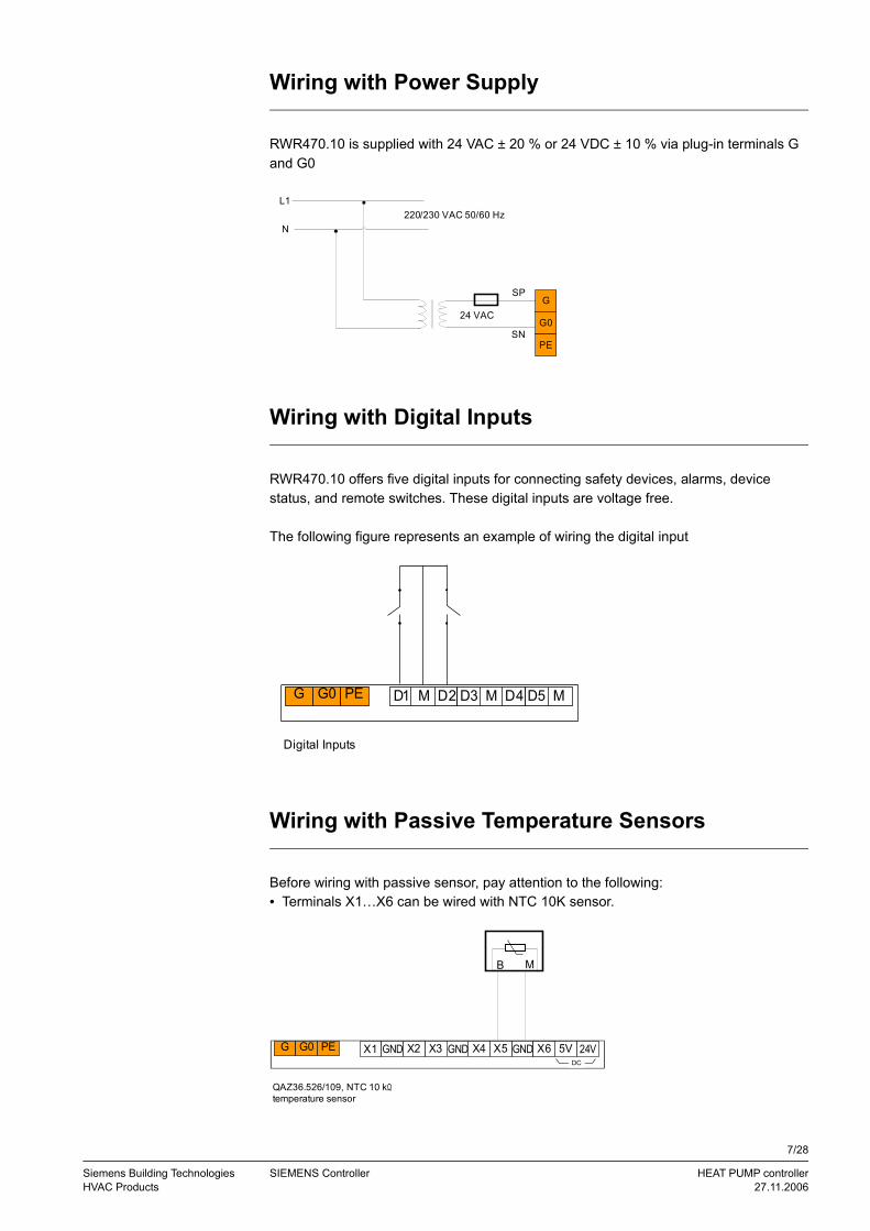
Wiring with Power Supply
RWR470.10 is supplied with 24 VAC ± 20 % or 24 VDC ± 10 % via plug-in terminals G and G0
L1
N220/230 VAC 50/60 Hz
24 VAC
SP
SN
G
G0
PE
Wiring with Digital Inputs
RWR470.10 offers five digital inputs for connecting safety devices, alarms, device status, and remote switches. These digital inputs are voltage free.
The following figure represents an example of wiring the digital input
D2 D3 M D4 D5 MD1 MG G0 PE
Digital Inputs
Wiring with Passive Temperature Sensors
Before wiring with passive sensor, pay attention to the following:• Terminals X1…X6 can be wired with NTC 10K sensor.
G G0 PE X3X1 X2 5VX5X4GND GND GND 24VDC
B M
QAZ36.526/109, NTC 10 kΩ temperature sensor
X6
7/28
Siemens Building Technologies SIEMENS Controller HEAT PUMP controllerHVAC Products 27.11.2006

Wiring with Digital Outputs
The following is a wiring example with relay output.
L 1N
E-heater
E-heater with 220/230 VAC supply voltage
Q13 Q14 Q24 Q34 Q44 Q54 Q64
Fuse
8/28
Siemens Building Technologies SIEMENS Controller HEAT PUMP controllerHVAC Products 27.11.2006

4 General Device Settings
Modes of Operation
The current RWR470.10 controller consists of three kinds of operation modes:
Mode Function
1 Normal working mode Display all running devices and measured values2 Menu mode* View configured analog inputs, warning and alarm logs
Set/adjust parameter values and also user privilege to parameters
3 Stop mode** Normally shut-down status (all units stop running.)*To enter menu mode, see also <Chapter 4.2. Accessing the Menus>.
• In normal working mode, the back light will be timed out after 30seconds without any operation.
Accessing the Menus
Display Procedures
.
+
-
In Stop mode, press the <Enter> button for 2 seconds and release it to enter the Menu mode. By default, the Query icon is blinking, waiting for further instructions.
To view the latest 10 warnings generated:• Navigate to the ! menu by pressing <Plus> or <Minus>, and then press <Enter> to
confirm and proceed.
To view the latest 20 alarms generated:• Navigate to the menu by pressing <Plus> or <Minus>, and then press <Enter>
to confirm and proceed.
To set parameter values:
• Navigate to the menu by pressing <Plus> or <Minus>, and then press <Enter> to confirm and proceed. Contents under this menu may vary with the privilege right of the user.
− For end users, select “NO,” and press <Enter > to proceed.− For service men and factory users, select “EU” or”ID”and press <Enter> to input
the password.
9/28
Siemens Building Technologies SIEMENS Controller HEAT PUMP controllerHVAC Products 27.11.2006
Notes
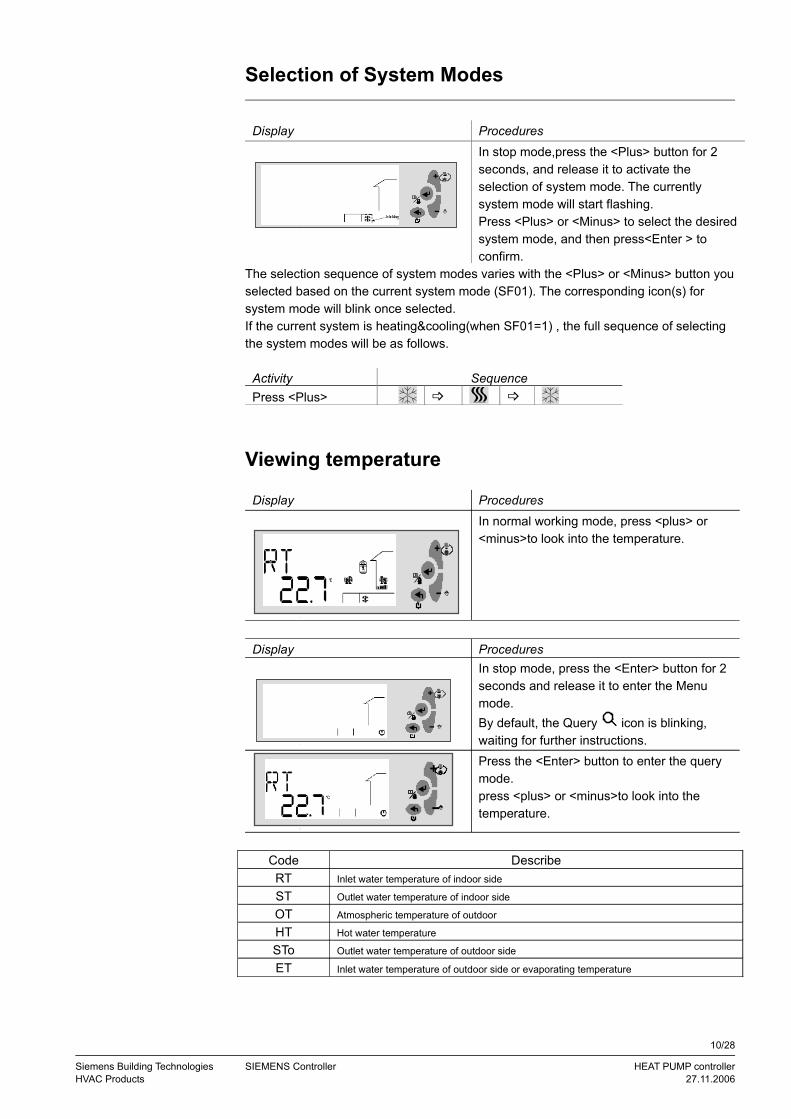
Selection of System Modes
Display Procedures
.
+
-
In stop mode,press the <Plus> button for 2 seconds, and release it to activate the selection of system mode. The currently system mode will start flashing.Press <Plus> or <Minus> to select the desired system mode, and then press<Enter > to confirm.
The selection sequence of system modes varies with the <Plus> or <Minus> button you selected based on the current system mode (SF01). The corresponding icon(s) for system mode will blink once selected. If the current system is heating&cooling(when SF01=1) , the full sequence of selecting the system modes will be as follows.
Activity SequencePress <Plus>
Viewing temperature
Display Procedures
.
+
-
In normal working mode, press <plus> or <minus>to look into the temperature.
Display Procedures
.
+
-
In stop mode, press the <Enter> button for 2 seconds and release it to enter the Menu mode. By default, the Query icon is blinking, waiting for further instructions.
.
+
-
Press the <Enter> button to enter the query mode. press <plus> or <minus>to look into the temperature.
Code DescribeRT Inlet water temperature of indoor side
ST Outlet water temperature of indoor side
OT Atmospheric temperature of outdoor
HT Hot water temperature
STo Outlet water temperature of outdoor side
ET Inlet water temperature of outdoor side or evaporating temperature
10/28
Siemens Building Technologies SIEMENS Controller HEAT PUMP controllerHVAC Products 27.11.2006

Changing Setpoints (for end users)
Display Procedures
In stop mode, press <Enter> for 2 seconds and release it to activate the Menu mode.
.
+
-
When the icon is blinking, press <Plus> or
<Minus> to navigate to the menu, and then press <Enter> to proceed.
Contents under the Parameter Menu may vary with the privilege right of the user.• For end users, select “NO,” and press <Enter > to proceed.• For service men and factory users, select “EU” or”ID”,and press <Enter> to input the
4-digit password .
.
+
-
For end users, parameters in the “ST” group will by default be displayed.
Press <Plus> and <Minus> to navigate to the parameter and press<Enter> to continue.
Or, continuously press <Esc> to exit out of the current level and back to the desired menu level.
The following list is parameters contained in the “ST” group.
Para-
meter
Descriptions De-
fault
Min. Max. Unit Res Privi-
legeST01 Setpoint of compressors in cooling mode (End User) 12 ST11 ST12 ºC/ 0.1 0
ST02 Setpoint of compressors in heating mode (End User) 40 ST13 ST14 ºC/ 0.1 0
ST03 Adjustable temperature band of compressor in Cooling mode 1 0 10 ºC 0.1 0
ST04 Adjustable temperature band of compressor in Heating mode 1 0 10 ºC 0.1 0
ST05 Setting temperature for heating temperature compensate function 20 0 30 ºC 0.1 0
ST06 Compensate factor for heating temperature compensate function 6 0 30 - 0.1 0
ST07 Temperature Scope of outside when the boiler started 0 -10 20 ºC 0.1 0
ST08 Setpoint of outside temperature when the boiler started 5 1 20 ºC 0.1 0
ST09 Setpoint of hotwater temperature in the life 50 ST15 ST16 ºC 0.1 0
ST10 Band of hotwater temperature in the life 3 1 10 ºC 0.1 0
ST11 Minimum setpoint in cooling 10 0 ST12 ºC 0.1 0
ST12 Maximum setpoint in cooling 40 ST11 60 ºC 0.1 0
ST17 Band of adjusting time 30 1 1000 Sec 1 0
11/28
Siemens Building Technologies SIEMENS Controller HEAT PUMP controllerHVAC Products 27.11.2006

5 Fast Configuration via PolyStick
Only trained staff can perform fast configuration via PolyStick.
Downloading Application and Parameters from PolyStick
To download application and parameters from PolyStick to the controller, follow steps below:• Power off the controller• Plug PolyStick into RJ45 service interface• Re-apply power to the controller• Wait while the green LED is continuously blinking, indicating the data communication
process• Once finished, the controller will be set in Stop mode, and the green LED fixed• Un-plug the PolyStick• Press <Esc> to activate the system from Stop mode
6 Customizing Application by Adjusting Parameter Values
Accessing the Parameter Menu
Display Procedures
In Stop mode, press <Enter> for 2 seconds and release it to activate the Menu mode.
When the icon is blinking, press <Plus> or <Minus> to navigate to the menu, and then press <Enter> to proceed.
Contents under the menu may vary with the privilege right of the user.• For end users, select “NO” and press <Enter > to proceed.• For service men and factory users, select “EU” or “ID”and press <Enter>. Input the
4-digit password when the following screen is displayed
.
+
-
Press <Enter> to confirm and continue to input the password.
12/28
Siemens Building Technologies SIEMENS Controller HEAT PUMP controllerHVAC Products 27.11.2006
Notes

.
+
-
Password is required for the sevice man and factory users.
To input password, follow the instructions below:• When the digit is blinking, press <Plus>/<Minus> to select the value. Then, press
<Enter> to confirm, and proceed to the next digit. • Or, press <Esc> at any time to cancel the input and return to the previous blinking
digit.• Repeat steps above to input other three numbers.• After inputting the password, press <Enter> to confirm, and proceed to setting
parameter values.
Adjusting Parameter Values
Display Procedures
After inputting password and enter into the parameter setting mode, the “ST” parameter group will by default be displayed.
Press <Plus> or <Minus> to select the parameter code, and press <Enter> to confirm.
The default value of the parameter will start flashing, allowing you to make a change.
Press <Plus> or <Minus> to increase or decrease the value, and press <Enter> to confirm.
Continuously press <Esc> to exit out of the current level and back to the desired menu level.
13/28
Siemens Building Technologies SIEMENS Controller HEAT PUMP controllerHVAC Products 27.11.2006
Input Password
Procedures
Notes
+
-
blinking5
blinking
5
+
-

7 Warning Management
When a warning is detected, the corresponding warning code will be displayed on the
LCD. The warning icon ! will flash simultaneously.
Only the latest 10 warnings will be kept under the ! menu. Upon power failure of the controller, the warning logs will be erased and recounted
Codes for Warnings
Ten types of warnings are used to monitor the system.
Codes MeaningWN00
WN01
Viewing Warning Logs
Display Procedures
Press down <Enter> for 2 seconds and release it to activate the Menu mode.
When the icon is flashing, press <Plus>/
<Minus> to navigate to the ! menu, and then press <Enter> to confirm.
Two letters “WN” will be displayed on the LCD, continuously flashing. Press <Enter> again to view the last 10 warning codes generated, if any.
If no warning is generated, the word “NoNE” will be displayed.
Continuously press <Exit> to exit out of the current level, and back to the normal running mode.
14/28
Siemens Building Technologies SIEMENS Controller HEAT PUMP controllerHVAC Products 27.11.2006
Notes
! blinking
+
-
+
-
!
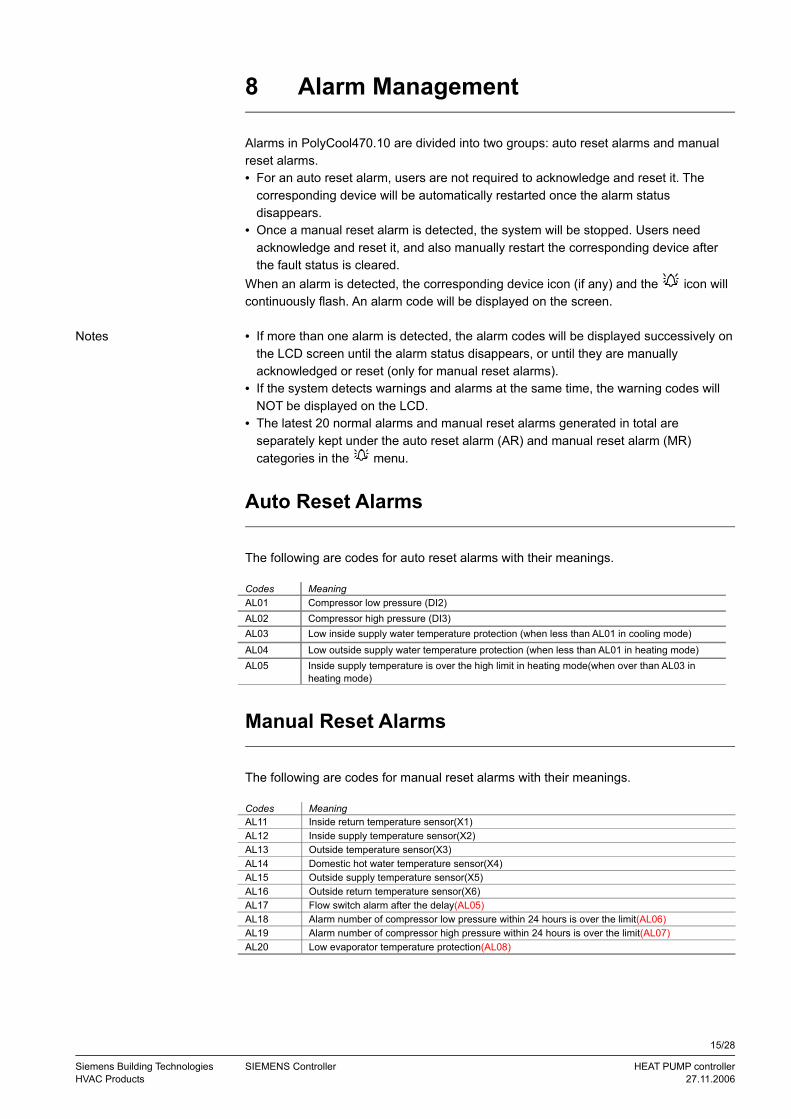
8 Alarm Management
Alarms in PolyCool470.10 are divided into two groups: auto reset alarms and manual reset alarms. • For an auto reset alarm, users are not required to acknowledge and reset it. The
corresponding device will be automatically restarted once the alarm status disappears.
• Once a manual reset alarm is detected, the system will be stopped. Users need acknowledge and reset it, and also manually restart the corresponding device after the fault status is cleared.
When an alarm is detected, the corresponding device icon (if any) and the icon will continuously flash. An alarm code will be displayed on the screen.
• If more than one alarm is detected, the alarm codes will be displayed successively on the LCD screen until the alarm status disappears, or until they are manually acknowledged or reset (only for manual reset alarms).
• If the system detects warnings and alarms at the same time, the warning codes will NOT be displayed on the LCD.
• The latest 20 normal alarms and manual reset alarms generated in total are separately kept under the auto reset alarm (AR) and manual reset alarm (MR) categories in the menu.
Auto Reset Alarms
The following are codes for auto reset alarms with their meanings.
Codes MeaningAL01 Compressor low pressure (DI2) AL02 Compressor high pressure (DI3)AL03 Low inside supply water temperature protection (when less than AL01 in cooling mode)AL04 Low outside supply water temperature protection (when less than AL01 in heating mode)AL05 Inside supply temperature is over the high limit in heating mode(when over than AL03 in
heating mode)
Manual Reset Alarms
The following are codes for manual reset alarms with their meanings.
Codes MeaningAL11 Inside return temperature sensor(X1)AL12 Inside supply temperature sensor(X2)AL13 Outside temperature sensor(X3)AL14 Domestic hot water temperature sensor(X4)AL15 Outside supply temperature sensor(X5)AL16 Outside return temperature sensor(X6)AL17 Flow switch alarm after the delay(AL05)AL18 Alarm number of compressor low pressure within 24 hours is over the limit(AL06)AL19 Alarm number of compressor high pressure within 24 hours is over the limit(AL07)AL20 Low evaporator temperature protection(AL08)
15/28
Siemens Building Technologies SIEMENS Controller HEAT PUMP controllerHVAC Products 27.11.2006
Notes

Viewing Alarm Logs
Display Procedures
Press down <Enter> for 2 seconds, and release it to activate the Menu mode. Press <Plus> or <Minus> to navigate to the
menu, and then press <Enter> to confirm.
By default, auto reset alarm “AR” will be displayed on the LCD, flashing.
To view auto reset alarms generated, press <Enter> to continue when “AR” is displayed.To view manual reset alarms, press<Minus> or <Plus> to navigate to the “MR” group, and then press <Enter> to continue.
By default, the first manual reset alarm “MR01” will be displayed as follows. Press <Enter> to view the first manual reset alarm code. Or, press<Minus> or <Plus> to view other numbered alarms, and press<Enter> to view the specific code.
If no alarm is generated, the word “NoNE” will be displayed.
Continuously press <Exit> to exit out of the current level, and back to the normal running mode.
MR01 and AR01 are respectively the latest information of manual reset alarm and auto reset alarm.
Acknowledging and Resetting Manual Reset Alarms
Any alarm detected by the system, either an auto reset alarm or a manual reset alarm, will be displayed on the LCD. However, only manual reset alarms require user’s acknowledgement and reset.
To do this, follow the steps below:• Press <Enter> to acknowledge the alarm.
• If the alarm status is cleared, the corresponding device icon and alarm icon that are flashing will accordingly disappear.
• Restart the system, as appropriate.
16/28
Siemens Building Technologies SIEMENS Controller HEAT PUMP controllerHVAC Products 27.11.2006
Note
+
-
5 5
+
-5
5
9 Main Control Logic
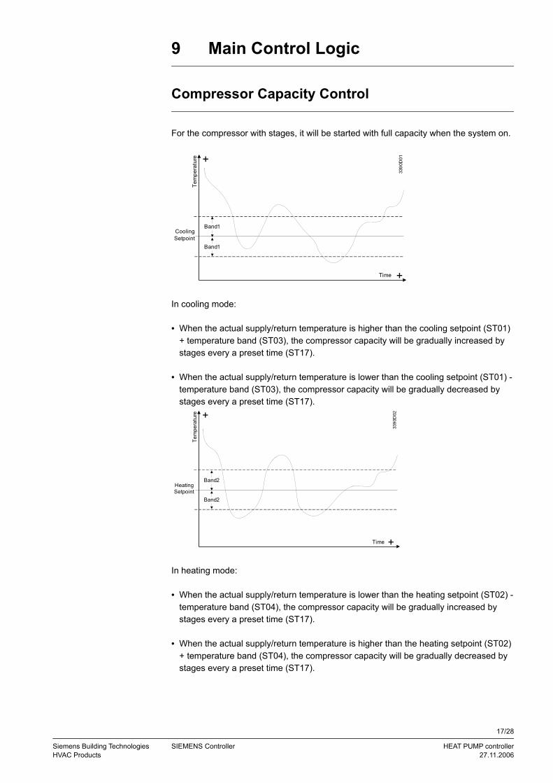
Compressor Capacity Control
For the compressor with stages, it will be started with full capacity when the system on.
Band1
Band1
Cooling Setpoint
Tem
pera
ture
Time
3390
D01
+
+
In cooling mode:
• When the actual supply/return temperature is higher than the cooling setpoint (ST01) + temperature band (ST03), the compressor capacity will be gradually increased by stages every a preset time (ST17).
• When the actual supply/return temperature is lower than the cooling setpoint (ST01) - temperature band (ST03), the compressor capacity will be gradually decreased by stages every a preset time (ST17).
Band2
Band2
Heating Setpoint
Tem
pera
ture
Time
3390
D02
+
+
In heating mode:
• When the actual supply/return temperature is lower than the heating setpoint (ST02) - temperature band (ST04), the compressor capacity will be gradually increased by stages every a preset time (ST17).
• When the actual supply/return temperature is higher than the heating setpoint (ST02) + temperature band (ST04), the compressor capacity will be gradually decreased by stages every a preset time (ST17).
17/28
Siemens Building Technologies SIEMENS Controller HEAT PUMP controllerHVAC Products 27.11.2006

Temperature compensation at HEAT
The controller offers two type of temperature control mode at heat mode. When SF04=0, the set-temperature at heat will be controlled by ST02; When SF04=1, the set-temperature at heat will be controlled by ambient-
temperature (OT) ,ST05 and ST06 according to the following formula:Set-temperature at HEAT =ST05+ST06 (ST05-OT)
The calculated temperature can be used for the control reference, but the maximum date will not exceed ST14
Boiler
At heat mode, BOILER works as follows: When OT<ST07, BOILER will run as a energy stage by the requirement of
temperature, but BOILER will be the last to get into running, the first to quite from working.
When OT>ST07+ST08, BOILER function will be cancelled.
3 way valve/ daily hot water pump control
When SF10=0, DO7 will control the 3 way valve. Both the indoor side water pump and 3 way valve will be turned on when running the daily hot water mode.
When SF10=1, DO7 will control the daily hot water pump. The indoor side water pump is OFF, the daily hot water pump will be ON when running daily hot water mode.
Alarm
the alert Produced namely output, the alert clearance namely stop exportation.
Control process
TURN ON process at HEATWhen operate TURN ON at heat mode, the controller will work as the following process:
9.6.1.1 Start the indoor side water pump, 4 way valve;9.6.1.2 With CN01 delay, start the outdoor side water pump;9.6.1.3 With CM05 delay, and the water flow switch turned on, at the same time the time data CM02 meeted, start one compressor.9.6.1.4 With CM03 delay, and the time data CM02 meeted, start the other compressor if has.
9.6.2 TURN OFF process at HEATWhen operate TURN OFF at heat mode, the controller will work as the following process:9.6.2.1 CM01 meeted, turn off one compressor;9.6.2.2 With CM04 delay, CM01 meeted, turn off the other compressor if has;
18/28
Siemens Building Technologies SIEMENS Controller HEAT PUMP controllerHVAC Products 27.11.2006
9.6.2.3 With CN02 delay, close outdoor side water pump;9.6.2.4 With EV03 delay, close indoor side water pump, 4 way valve.
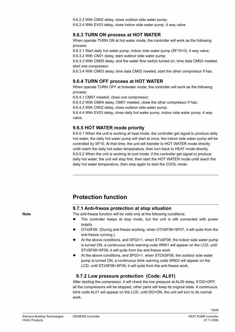
9.6.3 TURN ON process at HOT WATERWhen operate TURN ON at hot water mode, the controller will work as the following process:9.6.3.1 Start daily hot water pump, indoor side water pump (SF10=0), 4 way valve;9.6.3.2 With CN01 delay, start outdoor side water pump;9.6.3.3 With CM05 delay, and the water flow switch turned on, time data CM02 meeted, start one compressor.9.6.3.4 With CM03 delay, time data CM02 meeted, start the other compressor if has.
9.6.4 TURN OFF process at HOT WATERWhen operate TURN OFF at hotwater mode, the controller will work as the following process:9.6.4.1 CM01 meeted, close one compressor;9.6.4.2 With CM04 delay, CM01 meeted, close the other compressor if has;9.6.4.3 With CN02 delay, close outdoor side water pump;9.6.4.4 With EV03 delay, close daily hot water pump, indoor side water pump, 4 way valve.
9.6.5 HOT WATER mode priority9.6.5.1 When the unit is working at heat mode, the controller get signal to produce daily hot water, the daily hot water pump will start at once, the indoor side water pump will be controlled by SF10. At that time, the unit will transfer to HOT WATER mode directly untill reach the daily hot water temperature, then turn back to HEAT mode directly.9.6.5.2 When the unit is working at cool mode, if the controller get signal to produce daily hot water, the unit will stop first, then start the HOT WATER mode untill reach the daily hot water temperature, then stop again to start the COOL mode.
Protection function
9.7.1 Anti-freeze protection at stop situationThe anti-freeze function will be valid only at the following conditions: The controller keeps at stop mode, but the unit is still connected with power
supply. OT≤SF06 (During anti-freeze working, when OT≥SF06+SF07, it will quite from the
anti-freeze running.) At the above conditions, and SF02=1, when ST≤SF08, the indoor side water pump
is turned ON, a continuous blink warning code WN01 will appear on the LCD, until ST≥SF08+SF09, it will quite from the anti-freeze work.
At the above conditions, and SF03=1. when STO≤SF08, the outdoor side water pump is turned ON, a continuous blink warning code WN02 will appear on the LCD, until ST≥SF08+SF09, it will quite from the anti-freeze work.
9.7.2 Low pressure protection (Code: AL01)After starting the compressor, it will check the low pressure at AL09 delay. If DI2=OFF, all the compressors will be stopped, other parts will keep its original state. A continuous blink code AL01 will appear on the LCD, until DI2=ON, the unit will turn to its normal work.
19/28
Siemens Building Technologies SIEMENS Controller HEAT PUMP controllerHVAC Products 27.11.2006
Note
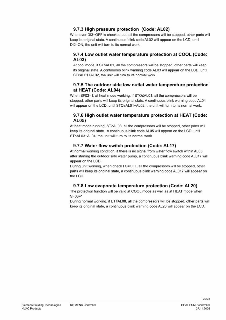
9.7.3 High pressure protection (Code: AL02)Whenever DI3=OFF is checked out, all the compressors will be stopped, other parts will keep its original state. A continuous blink code AL02 will appear on the LCD, until DI2=ON, the unit will turn to its normal work.
9.7.4 Low outlet water temperature protection at COOL (Code: AL03)At cool mode, if ST≤AL01, all the compressors will be stopped, other parts will keep its original state. A continuous blink warning code AL03 will appear on the LCD, until ST≥AL01+AL02, the unit will turn to its normal work.
9.7.5 The outdoor side low outlet water temperature protection at HEAT (Code: AL04)
When SF03=1, at heat mode working, if STO≤AL01, all the compressors will be stopped, other parts will keep its original state. A continuous blink warning code AL04 will appear on the LCD, until STO≥AL01+AL02, the unit will turn to its normal work.
9.7.6 High outlet water temperature protection at HEAT (Code: AL05)
At heat mode running, ST≥AL03, all the compressors will be stopped, other parts will keep its original state. A continuous blink code AL05 will appear on the LCD, until ST≤AL03+AL04, the unit will turn to its normal work.
9.7.7 Water flow switch protection (Code: AL17)At normal working condition, if there is no signal from water flow switch within AL05 after starting the outdoor side water pump, a continuous blink warning code AL017 will appear on the LCD.During unit working, when check FS=OFF, all the compressors will be stopped, other parts will keep its original state, a continuous blink warning code AL017 will appear on the LCD.
9.7.8 Low evaporate temperature protection (Code: AL20)The protection function will be valid at COOL mode as well as at HEAT mode when SF03=1During normal working, if ET≤AL08, all the compressors will be stopped, other parts will keep its original state, a continuous blink warning code AL20 will appear on the LCD.
20/28
Siemens Building Technologies SIEMENS Controller HEAT PUMP controllerHVAC Products 27.11.2006

10 Paramter Tables
Compressor Settings
<Second: Sec; Minute: Min; Hour: Hr>
Para-meter
Descriptions De-fault
Min.
Max. Unit Res. Privi-lege
CM01 Compressor minimum ON time 180 1 1000 Sec 1 1
CM02 Compressor minimum OFF time 180 1 1000 Sec 1 1
CM03 Start Delay between two compressors 10 0 100 Sec 1 1
CM04 Shut down delay between two compressors 30 0 1000 Sec 1 1
CM05 Compressor ON delay (outdoor pump ON) 10 0 150 Sec 1 1
CM06 The number of compressors 2 1 2 - 1 2
CM07 The direction indicator of four-way valves( 1 or 0 indicates heating mode)
1 0 1 1
CM08 Compressor consecutive running time for discard 30000 0 50000
Hr 10 1
Condenser Settings
Para-meter
Descriptions De-fault
Min Max Unit Res. Privi-lege
CN01 - outdoor pump ON delay (indoor pump ON) 10 0 150 Sec 1 1
CN02 outdoor pump ON delay (compressor OFF) 10 0 150 Sec 1 1
Evaporator Settings
Para-meter
Descriptions De-fault
Min. Max. Unit Res. Privi-lege
EV01 Control Mode- 0=pump with circulate continuously- 1= The water pump with the compressor ON/ OFF but
ON/ OFF
0 0 1 - 1 1
EV02 Indoor reference sensor:- - 0=RT (return temperature sensor)- 1=ST (supply temperature sensor)
0 0 1 - 1 1
EV03 indoor pump Off delay (compressor OFF) 60 CN02 1000 Sec 1 1
21/28
Siemens Building Technologies SIEMENS Controller HEAT PUMP controllerHVAC Products 27.11.2006

Special Functions
Para-
meter
Descriptions De-
fault
Min. Max. Unit Res. Privi-lege
SF01 System mode- 0=Cooling only- 1=Heating & Cooling - 2=Heating only
2 0 2 - 1 2
SF02 Indoor Antifreeze function- 0=Disabled- 1=Enabled
1 0 1 - 1 1
SF03 Outdoor Antifreeze function(Be applicable to the groundwater)- 0=Disabled- 1=Enabled
0 0 1 - 1 1
SF04 the compensates function of heating temperature- 0=Disabled- 1=Enabled
1 0 1 - 1 1
SF05 - Heat Recovery function- 0=Disabled- 1=Enabled
0 0 1 - 1 2
SF06 Outside temperature point for antifreeze turned on - 0=Disabled- 1=Enabled
2 0 10 1 1
SF07 Outside temperature scope for antifreeze turned off- 0=return temperature (RT)- 1=supply temperature (ST)
1 1 10 1 1
SF08 temperature point of inlet/outlet water for antifreeze turned on 3 1 10 1 1
SF09 temperature point of inlet/outlet water for antifreeze turned off 3 1 10 1 1
SF10 The compatibility between the Indoor water pump and hot water pump 0 1 1 1 1
22/28
Siemens Building Technologies SIEMENS Controller HEAT PUMP controllerHVAC Products 27.11.2006
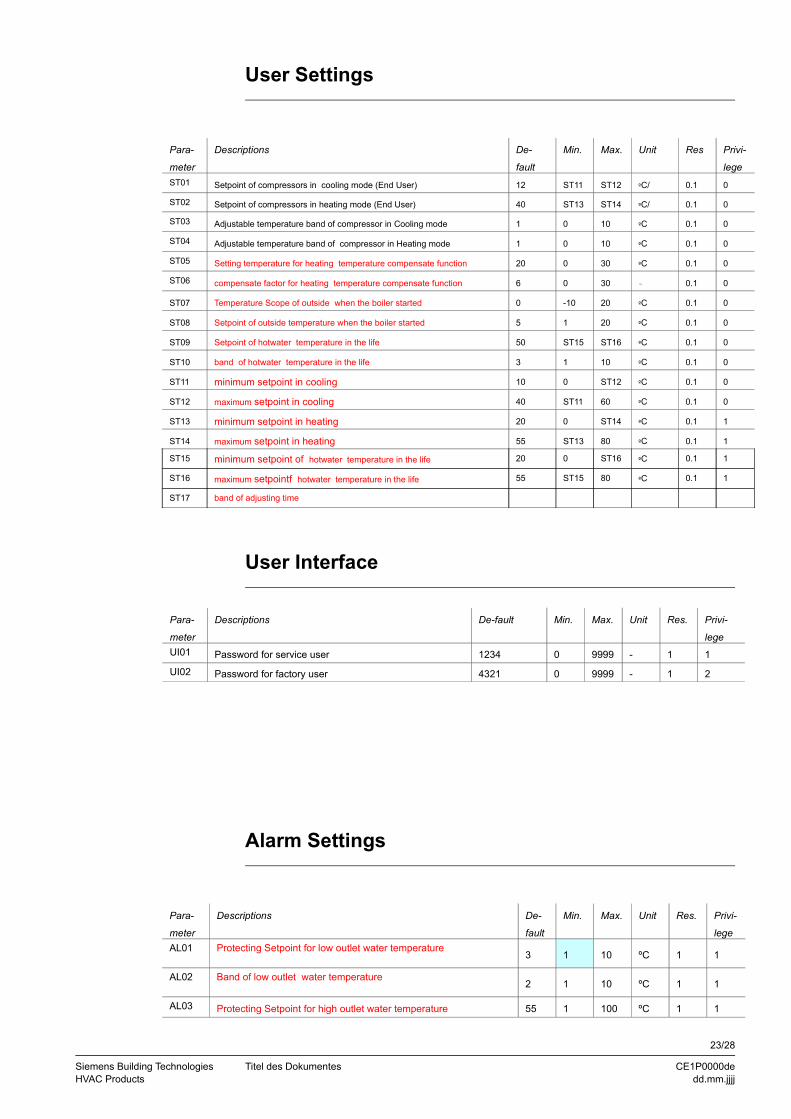
User Settings
Para-
meter
Descriptions De-
fault
Min. Max. Unit Res Privi-
legeST01 Setpoint of compressors in cooling mode (End User) 12 ST11 ST12 ºC/ 0.1 0
ST02 Setpoint of compressors in heating mode (End User) 40 ST13 ST14 ºC/ 0.1 0
ST03 Adjustable temperature band of compressor in Cooling mode 1 0 10 ºC 0.1 0
ST04 Adjustable temperature band of compressor in Heating mode 1 0 10 ºC 0.1 0
ST05 Setting temperature for heating temperature compensate function 20 0 30 ºC 0.1 0
ST06 compensate factor for heating temperature compensate function 6 0 30 - 0.1 0
ST07 Temperature Scope of outside when the boiler started 0 -10 20 ºC 0.1 0
ST08 Setpoint of outside temperature when the boiler started 5 1 20 ºC 0.1 0
ST09 Setpoint of hotwater temperature in the life 50 ST15 ST16 ºC 0.1 0
ST10 band of hotwater temperature in the life 3 1 10 ºC 0.1 0
ST11 minimum setpoint in cooling 10 0 ST12 ºC 0.1 0
ST12 maximum setpoint in cooling 40 ST11 60 ºC 0.1 0
ST13 minimum setpoint in heating 20 0 ST14 ºC 0.1 1
ST14 maximum setpoint in heating 55 ST13 80 ºC 0.1 1
ST15 minimum setpoint of hotwater temperature in the life 20 0 ST16 ºC 0.1 1
ST16 maximum setpointf hotwater temperature in the life 55 ST15 80 ºC 0.1 1
ST17 band of adjusting time
User Interface
Para-
meter
Descriptions De-fault Min. Max. Unit Res. Privi-
legeUI01 Password for service user 1234 0 9999 - 1 1
UI02 Password for factory user 4321 0 9999 - 1 2
Alarm Settings
Para-
meter
Descriptions De-
fault
Min. Max. Unit Res. Privi-
legeAL01 Protecting Setpoint for low outlet water temperature
3 1 10 ºC 1 1
AL02 Band of low outlet water temperature 2 1 10 ºC 1 1
AL03 Protecting Setpoint for high outlet water temperature 55 1 100 ºC 1 1
23/28
Siemens Building Technologies Titel des Dokumentes CE1P0000deHVAC Products dd.mm.jjjj
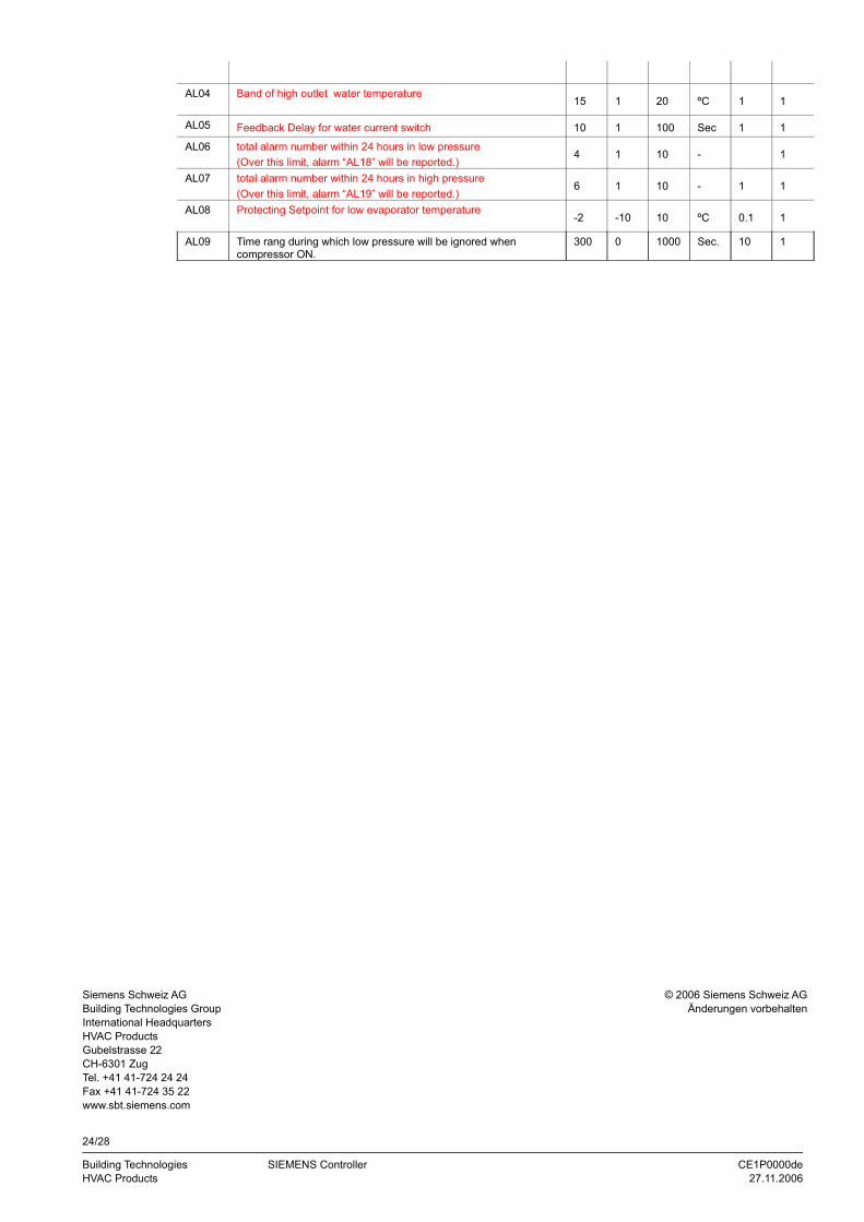
AL04 Band of high outlet water temperature 15 1 20 ºC 1 1
AL05 Feedback Delay for water current switch 10 1 100 Sec 1 1
AL06 total alarm number within 24 hours in low pressure(Over this limit, alarm “AL18” will be reported.)
4 1 10 - 1
AL07 total alarm number within 24 hours in high pressure(Over this limit, alarm “AL19” will be reported.)
6 1 10 - 1 1
AL08 Protecting Setpoint for low evaporator temperature-2 -10 10 ºC 0.1 1
AL09 Time rang during which low pressure will be ignored when compressor ON.
300 0 1000 Sec. 10 1
24/28
Building Technologies SIEMENS Controller CE1P0000deHVAC Products 27.11.2006
Siemens Schweiz AGBuilding Technologies GroupInternational HeadquartersHVAC ProductsGubelstrasse 22CH-6301 ZugTel. +41 41-724 24 24Fax +41 41-724 35 22www.sbt.siemens.com
© 2006 Siemens Schweiz AGÄnderungen vorbehalten