Polycom SoundStructure Version 1.3 Including Events, … · 1 Introduction This document provides...
39
©2009 Polycom, Inc. All rights reserved. Polycom and the Polycom logo design are registered trademarks of Polycom, Inc. All other trademarks are the property of their respective owners. Information is subject to change without notice. 1 This document introduces the new features of SoundStructure v1.3 and presents how to use SoundStructure’s Events engine to build applications using the logic ports, the HDX IR remote, and for integrating the HDX video codec and HDX microphones. 1 Introduction This document provides an overview of the new features and performance enhancements of the version 1.3 SoundStructure Studio and SoundStructure firmware and introduces the concept of events and how events may be used with logic input and output pins and with the HDX IR remote. Common applications are presented to help understand how to use these new concepts of events, logic, and IR. 2 New Features in version 1.3 Version 1.3 includes the following new features: • Full support for logic inputs, logic outputs, and IR receiver port • Event engine for customizing the behavior of SoundStructure based on logic inputs, IR receiver inputs, and a number of other SoundStructure parameters • Zero Configuration network support • 10 new ring tones for the PSTN interface • Auto-Hangup feature based on call progress tones (busy, fast busy, offhook) • Serial port broadcast mode for sending commands to other devices • Ability to pause the command processor to insert delays in the command processing • Signal activity meter that can be used as a source in events • Version 30 firmware for HDX microphones • ‘online’ RS232 acknowledgment upon power up Using logic inputs, outputs, IR receiver port, and the event engine will be described in Section 3. 2.1 Zero Configuration Network Support SoundStructure devices running version 1.3 firmware continue to look for a DHCP server to provide an IP address. However, if no DHCP server is available when the device boots up, a valid link-local IP address is created and used by the SoundStructure device, enabling Ethernet connectivity to the SoundStructure device. In the absence of a DHCP server, SoundStructure devices will use the default IP address of Polycom ® SoundStructure Version 1.3 Including Events, Logic, and IR support
Transcript of Polycom SoundStructure Version 1.3 Including Events, … · 1 Introduction This document provides...

©2009 Polycom, Inc. All rights reserved. Polycom and the Polycom logo design are registered trademarks of Polycom, Inc. All other trademarks are the property of their respective owners. Information is subject to change without notice.
1
This document introduces the new features of SoundStructure v1.3 and presents how to use SoundStructure’s Events engine to build applications using the logic ports, the HDX IR remote, and for integrating the HDX video codec and HDX microphones.
1 Introduction This document provides an overview of the new features and performance enhancements of the version 1.3 SoundStructure Studio and SoundStructure firmware and introduces the concept of events and how events may be used with logic input and output pins and with the HDX IR remote. Common applications are presented to help understand how to use these new concepts of events, logic, and IR.
2 New Features in version 1.3 Version 1.3 includes the following new features:
• Full support for logic inputs, logic outputs, and IR receiver port
• Event engine for customizing the behavior of SoundStructure based on logic inputs, IR receiver inputs, and a number of other SoundStructure parameters
• Zero Configuration network support
• 10 new ring tones for the PSTN interface
• Auto-Hangup feature based on call progress tones (busy, fast busy, offhook)
• Serial port broadcast mode for sending commands to other devices
• Ability to pause the command processor to insert delays in the command processing
• Signal activity meter that can be used as a source in events
• Version 30 firmware for HDX microphones
• ‘online’ RS232 acknowledgment upon power up
Using logic inputs, outputs, IR receiver port, and the event engine will be described in Section 3.
2.1 Zero Configuration Network Support SoundStructure devices running version 1.3 firmware continue to look for a DHCP server to provide an IP address. However, if no DHCP server is available when the device boots up, a valid link-local IP address is created and used by the SoundStructure device, enabling Ethernet connectivity to the SoundStructure device. In the absence of a DHCP server, SoundStructure devices will use the default IP address of
Polycom® SoundStructure Version 1.3 Including Events, Logic, and IR support

©2009 Polycom, Inc. All rights reserved. Polycom and the Polycom logo design are registered trademarks of Polycom, Inc. All other trademarks are the property of their respective owners. Information is subject to change without notice.
2
169.254.1.1 unless that address creates a conflict on the local network in which case a different link-local IP address will be generated.
Assuming the computer that is running SoundStructure Studio also does not have an IP address provided by a DHCP server, the local computer will also have a link-local address of the form 169.254.abc.def. The computer may be connected either directly to the SoundStructure device or connected through a network to the SoundStructure device, and then SoundStructure Studio will be able to automatically discover and connect to the SoundStructure device. When connected directly to the device, the local computer may use either with a straight-through or cross-over Cat5 cable.
The following figure shows how the SoundStructure device gets its IP address. If there is a static IP address assigned to SoundStructure, then that address will be used. If there is a DHCP server, then the SoundStructure device will use the address provided by the DHCP server. If there is no DHCP server, then the SoundStructure device will use a locally generated link-local IP address which will default to 169.254.1.1 assuming this does not create a conflict with a different device on the network.
Please note that when the SoundStructure device has a link-local IP address, if a DHCP server comes online at a later time, the SoundStructure device will accept an IP address provided by the DHCP server and will no longer have the link-local IP address.
If a fixed IP address is desired for a SoundStructure device, we recommend setting a static IP address. Once the static address is specified and the Apply button is pressed, SoundStructure Studio will be disconnected from the device. Reconnect to the SoundStructure device at the new static IP address and then save the project file to force the IP address to be written permanently into the SoundStructure device.
Use the File Save (or File Save As) option within SoundStructure Studio to save the project file when connected online to permanently store the SoundStructure device’s IP address.
2.2 10 New PSTN Ring Tones SoundStructure firmware version 1.3 adds 10 new ring tones to the SoundStructure telephony interface. These ring tones are heard when there is an incoming call. The ring tones are selected with the new SoundStructure parameter phone_ring_tone. The default ring tone is the traditional phone ring tone (phone_ring_tone = 1). The new ring tones are summarized in the table below.
Ring tone Description 1 Normal ring

©2009 Polycom, Inc. All rights reserved. Polycom and the Polycom logo design are registered trademarks of Polycom, Inc. All other trademarks are the property of their respective owners. Information is subject to change without notice.
3
2 Low Trill 3 Low Double Trill 4 Medium Trill 5 Medium Double Trill6 High Trill 7 High Double Trill 8 Highest Trill 9 Highest Double Trill 10 Beeble 11 Triplet
2.3 Call Progress Auto-Hangup SoundStructure firmware version 1.3 includes the ability to automatically hang up any of the PSTN phone interfaces based on the call progress tones of busy, fast busy, and offhook.
To enable this feature, select the Auto Hangup (Call Progress) option from the phone settings page. The default value for Auto Hangup (Call Progress) is disabled.
There is a new SoundStructure parameter, pstn_auto_hangup_call_prog_en, that enables or disables this functionality.
2.4 Serial Port Broadcast Mode SoundStructure firmware version 1.3 includes a broadcast mode for the serial port that allows the SoundStructure device to send commands to other devices. The serial port may be in one of two modes – command or broadcast. The default mode for the serial port is command mode. Command mode is compatible with third party control systems such as AMX and Crestron and allows the SoundStructure system to be fully controlled or configured.
Broadcast mode allows the SoundStructure device to send arbitrary commands from the selected serial port to control other devices. When in broadcast mode, any data received on the serial port is ignored. To set the serial port into broadcast mode, utilize the new SoundStructure Studio control on the wiring page as shown in the following figure. To select this mode, select “Broadcast mode”, hit Apply, and save the configuration file to ensure the settings are stored permanently within the SoundStructure device.
One application for broadcast mode is to select camera presets on a video codec that is connected to a SoundStructure device over a straight-through RS232 interface cable. As shown in the following figure, the cable has a male DB9 connector on one end and a female DB9 connector on the other end.

©2009 Polycom, Inc. All rights reserved. Polycom and the Polycom logo design are registered trademarks of Polycom, Inc. All other trademarks are the property of their respective owners. Information is subject to change without notice.
4
There is a new SoundStructure parameter, ser_control_mode, to support changing the serial port mode and a new parameter ser_send that can be used to send arbitrary commands to other devices. See the SoundStructure parameters.html file (or browse into the SoundStructure) for more information on how to use the ser_send parameter. There are examples later in this document for how to use this capability to support camera positioning.
Please note, when a SoundStructure device’s serial port is in Broadcast mode, the SoundStructure system cannot be controlled or configured with SoundStructure Studio, or a control system, over that one particular serial port. Ethernet control and serial control on other devices are not affected by the serial port Broadcast mode on a given device.
2.5 Command Processor Pause SoundStructure firmware version 1.3 adds a new parameter, sys_pause, that pauses the system’s command processor for the specified number of milliseconds which means that any commands that are sent to SoundStructure during this time from a control system or from SoundStructure Studio will be queued up and not executed during the sys_pause time.
The parameter sys_pause can be used to add delays in the command processing system. For example, to create a one second tone burst, a partial preset could be created that unmutes the signal generator to an output, pauses for one second, and then mutes the signal generator as shown in the following figure.

©2009 Polycom, Inc. All rights reserved. Polycom and the Polycom logo design are registered trademarks of Polycom, Inc. All other trademarks are the property of their respective owners. Information is subject to change without notice.
5
When the command processor is paused with the sys_pause parameter, the command processor will not process commands from any other control ports (Ethernet, IR, logic input, serial, etc.) during the sys_pause time.
2.6 Signal Activity Meter SoundStructure firmware version 1.3 includes a signal activity meter. This meter can be used as a source with the events engine. The threshold for the signal activity is set for all audio channels at once with the signal_activity_thresh parameter.
2.7 Version 30 HDX Microphone Firmware SoundStructure firmware version 1.3 includes the version 30 HDX microphone firmware. Version 30 firmware makes more efficient usage of the microphone resources and reduces the power requirement of the HDX microphones. Updating the SoundStructure firmware to version 1.3 will automatically cause HDX table and ceiling microphones that are connected to the SoundStructure device to be updated if there is no HDX video codec connected over conference link. Current HDX video codec firmware releases include version 30 firmware.
2.8 ‘online’ RS232 acknowledgment When the SoundStructure device has finished booting, the string “online” will be sent out the serial port interface to indicate the system has finished booting. This can be used by a control system that is connected over the serial port as an indicator that it can now send commands to a SoundStructure system. This string is only sent to the serial interface not the network interface.
2.9 Performance Improvements in Version 1.3 Version 1.3 includes the performance improvements in the following table.
Improvement Description
40ft OBAM cables OBAM has been improved to support 1394b Beta cables with lengths of up to 40ft. Standard high quality 1394b Beta cables may be used with SoundStructure. A 40ft OBAM cable is available from Polycom with part number 2200-43229-001.
Gateway address not required to allow SoundStructure Studio to discover a device
It is no longer a requirement when setting a static IP address to set a valid gateway address to allow SoundStructure Studio to automatically discover the SoundStructure device when on the same subnet
Faster preset execution The execution speed of both partial presets and full presets has been significantly improved. Partial presets may be used more efficiently now for volume control, changing routing settings, and other simple changes to the system. Full presets execute faster on SoundStructure systems.
PSTN calls can illuminate Using SoundStructure events and the new clink_call_active

©2009 Polycom, Inc. All rights reserved. Polycom and the Polycom logo design are registered trademarks of Polycom, Inc. All other trademarks are the property of their respective owners. Information is subject to change without notice.
6
the HDX table microphones green
and clink_local_call_active parameters, the SoundStructure PSTN interfaces can light the HDX table microphones green when in an active PSTN call.
Reduced boot time SoundStructure systems built from either single devices or large multi-device systems will finish the boot process in under two minutes.
Static IP address Static IP addresses of SoundStructure devices now remain with the device regardless of whether a device has been OBAM linked with other devices or has a configuration file that doesn’t match the hardware (yellow front panel LED state).
Stereo linking for dynamics and AGC
Stereo virtual channels now have the dynamics and AGC processing of both left and right channels linked together to ensure the stereo image is not affected by gains applied to the underlying left and right channels.
Synchronized clink mute Using SoundStructure events and the new SoundStructure parameter clink_mute, the clink mute state can be synchronized across multiple SoundStructure devices that are linked with OBAM. This ensures that the red mute light on HDX table microphones will be illuminated across multiple SoundStructure devices.
2.10 New SoundStructure Parameters The new SoundStructure parameters that may be used with API commands are shown and described in the following table. For more detailed information API information, browse into a SoundStructure device and search for the command of interest.
Command Description clink_call_active Indicates whether there is an active video call on
an HDX connected to the particular SoundStructure device.
clink_local_call_active Can be used to indicate whether there is an active call (HDX video or SoundStructure PSTN) on a particular SoundStructure device. When clink_local_call_active is one or greater on a particular SoundStructure device, the HDX table microphone LEDs will illuminate green on that device.
clink_mute Controls the mute state on the conference link interfaces for the particular SoundStructure device. Controls the mute state for any HDX codecs that are connected to that particular SoundStructure device. When clink_mute is true

©2009 Polycom, Inc. All rights reserved. Polycom and the Polycom logo design are registered trademarks of Polycom, Inc. All other trademarks are the property of their respective owners. Information is subject to change without notice.
7
for a given SoundStructure device, HDX table microphones connected to that SoundStructure device will illuminate red.
clink_volume Controls the volume level on the conference link interfaces for the particular SoundStructure devices. This parameter may be used to map the volume from the HDX to a fader on SoundStructure.
digital_gpio_held Specifies that the particular logic input pin has been held for the digital_gpio_hold_time in the closed position (digital_gpio_held = 1).
digital_gpio_hold_time Specifies the amount of time that a logic input pin must be held before the first digital_gpio_held message is sent.
digital_gpio_repeat_time Specifies the amount of time in milliseconds between digital_gpio_held messages when a button is continually held in the closed position (logic input switch closed = logic input value of 0).
ir_chan_id Specifies the IR channel ID that the SoundStructure and IR remote transceiver use. This allows multiple IR transmitters and receivers to be used in the same room. Defaults to 3 which is also the default for the HDX IR remote.
phone_ring_tone Selects the incoming telephone ring tone pstn_auto_hangup_call_prog_en Enables being able to automatically hangup the
phone line based on tones from the central office or PBX when the remote party hangs up the telephone call.
ser_control_mode Sets the serial port mode to be either in broadcast or command mode. Command mode is the default.
ser_send Used to send arbitrary commands out the RS232 interface when the serial port is in broadcast mode.
signal_activity_thresh Specifies the threshold for the signal activity meter.
sys_pause Pauses the command processor for up to 5 seconds

©2009 Polycom, Inc. All rights reserved. Polycom and the Polycom logo design are registered trademarks of Polycom, Inc. All other trademarks are the property of their respective owners. Information is subject to change without notice.
8
2.11 Backward Compatibility with Previous Firmware and Studio Releases SoundStructure firmware version 1.3 is compatible with configuration files created with pre-1.3 versions of SoundStructure Studio. SoundStructure devices with earlier firmware and configuration files may be updated to version 1.3 firmware and it is expected that the system will operate as well as with the previous firmware.
SoundStructure Studio version 1.3 supports the events and logic pin definitions and is compatible with SoundStructure devices that have earlier versions of firmware. Configuration files that include events, IR, and logic inputs/outputs are not compatible with SoundStructure devices with pre 1.3 firmware and will not be transferred to devices with pre 1.3 firmware.
When pre-1.3 SoundStructure Studio scans a SoundStructure device with version 1.3 firmware and ‘gets’ the configuration file, the configuration file will not contain any event definitions. This could cause an issue if the retrieved configuration file is ‘sent’ to other SoundStructure devices with the expectation that the events will be part of the configuration file. To avoid this issue, it is recommended that the latest version of SoundStructure Studio be used for all installations regardless of the firmware version of the SoundStructure device.
SoundStructure Studio versions before v1.3 are not able to display events that may be part of a configuration file. While preset changes and file saves will not disrupt the events within the SoundStructure device, the file saved to disk will not contain any event definitions.

©2009 Polycom, Inc. All rights reserved. Polycom and the Polycom logo design are registered trademarks of Polycom, Inc. All other trademarks are the property of their respective owners. Information is subject to change without notice.
9
3 Events SoundStructure Studio and firmware version 1.3 introduces the new concept of Events. Events are a very flexible way to cause specified actions to occur based on a source and a trigger. Events are used to connect logic input pins to control settings within SoundStructure such as executing presets based on logic pin changes, or muting microphones based on a button push. Events are also used to integrate the HDX IR remote controller with a SoundStructure device, allowing the different key presses to execute functions within SoundStructure such as taking the PSTN interface offhook, dialing digits, or muting microphones.
3.1 Sources The source defines the set of parameters that can be used to make something happen within SoundStructure. Sources may be button pushes, IR key presses, or particular SoundStructure parameters. The event sources that are allowed within SoundStructure are shown in the following table.
Event Sources
Safety mute HDX mute status
HDX volume status Temperature status
Mute state Call Status
Gating status Fader value
Signal activity status Camera gating status
Phone ring Phone hook status
Digital logic inputs held Digital logic inputs
IR keypress Analog logic input values
IR key held
3.2 Triggers The trigger determines when the information in the source becomes actionable. Triggers may be one of three values: always, equals, or range as defined below.
• The always trigger means that any time the source parameter changes, the action will execute.
• The equals trigger means that when the source parameter equals the desired value (e.g., open or closed for logic inputs), the action will execute.
• The range trigger means that anytime the source parameter value is equal to or greater than the min value and less than or equal to the max value, the action will execute.
Triggers are ‘edge’ triggered, meaning that when the source parameter value changes, the event engine will determine whether the trigger condition is met or not. For example, for logic input switches this means there are two edges – when a logic input is closed (has a value of 0), or when a logic input is opened (has a value of 1).
©2009 Polycom, Inc. All rights reserved. Polycom and the Polycom logo design are registered trademarks of Polycom, Inc. All other trademarks are the property of their respective owners. Information is subject to change without notice.
10
The following figure shows the two signal edges associated with a button press – the transition from open to closed and from closed to open. Either edge, or both edges, may be used to trigger events.
3.3 Actions The action specifies what happens when the trigger condition is met. Actions include
• running a particular command,
• running a preset, or
• mapping the value of the source parameter to a destination parameter.
Running a command allows the event to directly execute a single command to change a SoundStructure parameter via a valid API command. An example is muting all microphones as the action for when a button is pressed.
Running a preset allows the event to execute either a partial or full preset. An example of this type of action is changing the room matrix routing when a button is pressed.
Mapping a parameter allows the value of the destination parameter to track the value of the source parameter with a single event. Both Boolean parameters (with values of only 0 or 1, e.g., mute state) and numeric parameters (with values from a min to a max value, e.g., fader value) may be mapped.
Action maps may also be inverted to allow for the case where it is desired for the destination parameter map to be the inverse of the source parameter. An example of mapping Boolean parameters is shown in the following figure with both a direct mapping (true true) and an inverted mapping (true false).

©2009 Polycom, Inc. All rights reserved. Polycom and the Polycom logo design are registered trademarks of Polycom, Inc. All other trademarks are the property of their respective owners. Information is subject to change without notice.
11
An example of mapping a Boolean parameter would be tying the mute state of a microphone to the logic output state that drives an LED. Changes in the mute state of a microphone would be mapped directly to a logic output pin.
Numeric parameters can also be used in action maps. An example of mapping a numeric parameter is mapping the analog voltage from the logic inputs to the fader of a particular channel. In the example shown in the following figure (left), the values from the volume knob are mapped to a fader. The analog voltage values from the volume knob range from 0 to 255 and are directly mapped to the fader range of -100 to +20dB. Changes in the analog input voltage map directly to the fader values in a linear fashion.
In addition, if the user min and max values of the fader channel are used, the action map will automatically use the user min and max range instead of the full -100 to +20 dB range. Using a min/max range on the output parameter is shown on the right side of the figure where the user min has been set to -20 and the user max has been set to +10.

©2009 Polycom, Inc. All rights reserved. Polycom and the Polycom logo design are registered trademarks of Polycom, Inc. All other trademarks are the property of their respective owners. Information is subject to change without notice.
12
4 Creating Events with SoundStructure Studio SoundStructure Studio allows the A/V designer to create events with the Add Event button on the Events page. As we’ll see shortly there are a number of events that will be created automatically.
4.1 Adding New Events Clicking the add event button will show a user control that allows the designer to create an event name and then the source, trigger, and action. Similar to channel names, event names must be unique and are case sensitive. We recommend you use a name that will make sense to you.
To create an event, select the source, the trigger, and the type of action and select Add.
Once the events are created, the events page will show the entire list of events as shown in the following figure. The events page may be sorted by any of the column headings including the Event Name, Source, Parameter, Trigger, and Action.
Events may be edited by double clicking on an event on the Events page. Once completed, click Save to save the event or cancel to not save the event.
4.2 Enable and Disable Events Events may be enabled or disabled by checking or unchecking, respectively, the box to the left of the Event name. Disabling events is intended to simplify troubleshooting a system that may have many events. Once events are enabled, the trigger will be re-evaluated for all map actions and the resulting action executed.
The Enable All and Disable All buttons will enable or disable all events that have been defined.
To permanently store the enable/disable state of an event, save the configuration file to disk using File Save or File Save As. When connected online to a SoundStructure system, the File Save or File Save as will force the settings in the device to be written to the flash memory of the device.

©2009 Polycom, Inc. All rights reserved. Polycom and the Polycom logo design are registered trademarks of Polycom, Inc. All other trademarks are the property of their respective owners. Information is subject to change without notice.
13
4.3 Event entries in the logs The SoundStructure device logs record which events executed and the resulting command acknowledgments there were generated. An example log file is shown below where the events that executed are highlighted. If in doubt whether events are executing, check the logs within a SoundStructure system. Oct 10 23:05:18 gcp: cmd: [1:6:172.25.240.31] set mute "Table Mic" 1
Oct 10 23:05:18 gcp: sts: event "Table Mic LED Event" triggered
Oct 10 23:05:18 gcp: ack: [all] val digital_gpio_state "Table Mic LED" 0
Oct 10 23:05:18 gcp: sts: event "Table Mic Mute Event" triggered
Oct 10 23:05:18 gcp: sts: event "CLink to Mics Mute" triggered
Oct 10 23:05:18 gcp: ack: [all] val mute "Lectern Mic" 1
Oct 10 23:05:18 gcp: sts: event "Table Mic A Mute Event" triggered
Oct 10 23:05:18 gcp: ack: [all] val mute "Table Mic A" 1
Oct 10 23:05:18 gcp: sts: event "Table Mic B Mute Event" triggered
Oct 10 23:05:18 gcp: ack: [all] val mute "Table Mic B" 1
Oct 10 23:05:18 gcp: sts: event "Table Mic C Mute Event" triggered
Oct 10 23:05:18 gcp: ack: [all] val mute "Table Mic C" 1
Oct 10 23:05:18 gcp: ack: [all] val clink_mute 1 1

©2009 Polycom, Inc. All rights reserved. Polycom and the Polycom logo design are registered trademarks of Polycom, Inc. All other trademarks are the property of their respective owners. Information is subject to change without notice.
14
Oct 10 23:05:18 gcp: ack: [all] val mute "Table Mic" 1
4.4 Removing Events with Studio Events may be removed by selecting one or more events and choosing the Remove Event button on the events page.
4.5 SoundStructure Studio Automatically Creates Events When a new project is created, SoundStructure Studio will automatically create events depending on the input and output options selected. For example,
• If an HDX codec is added to a project, new events for volume control and mute are created. These new events replace the pre-1.3 requirement to use the virtual channel names “Mics” and “Amplifier”.
• If PSTN interfaces are added to a project, events for tracking the call active state (onhook/offhook) are created.
• If push-to-talk microphones are added, events for muting the microphones and for illuminating status LED’s are created.
• If an HDX IR remote is selected, events mapping the key presses on the IR remote to the appropriate functions within SoundStructure are created.
4.5.1 Backwards Compatibility with earlier SoundStructure firmware As described in this section, SoundStructure device firmware 1.3 uses events to handle the muting and volume control integration between an HDX and a SoundStructure device. In pre-1.3 versions of SoundStructure firmware, the names “Mics” and “Amplifier” were required for integrating the HDX Mute and Volume control to SoundStructure devices. If those names were not defined in the SoundStructure device, the HDX was not able to control the SoundStructure device. SoundStructure device version 1.3 firmware uses a different and better way to handle the HDX muting and volume control.
1. If there are no events defined for the SoundStructure device, the earlier firmware behavior is retained and the names “Mics” and “Amplifier” are required for the HDX to control the SoundStructure device. This backward compatibility mode means that the SoundStructure system will behave as it did prior to the firmware upgrade when there were no events defined.
2. When the SoundStructure device is upgraded to the 1.3 or later firmware, defining any events using the Add Events feature will cause SoundStructure Studio to automatically create the necessary SoundStructure events for the HDX and SoundStructure device integration.
The following figure shows that the “Mics” and “Amplifier” names from earlier firmware are required until any event is added. At that point, SoundStructure Studio will create all the necessary events to support the integration with events. Once the new events are created, the new events are used for the integration and the name “Mics” and “Amplifier” are no longer required for HDX integration.

©2009 Polycom, Inc. All rights reserved. Polycom and the Polycom logo design are registered trademarks of Polycom, Inc. All other trademarks are the property of their respective owners. Information is subject to change without notice.
15
Please note that to maintain backwards compatibility with the earlier versions of firmware and HDX integration, the “Amplifier” fader channel now has user min and max values set to -31 and +20 respectively. This means that the fader on the “Amplifier” channel will not go lower than -31dB without changing the fader user min value to a lower value.
4.5.2 HDX Codec Integration Events When an HDX codec is designed as part of a SoundStructure project the following events are automatically generated.
Event Name Description
Polycom HDX to SST Volume Maps user volume adjustments from the HDX (from HDX IR keypresses or from the HDX being controlled externally) to the fader on the channel “Amplifier”
SST to Polycom HDX Volume Maps any user fader adjustments on the first SoundStructure amplifier channel to the HDX volume
Clink to Mics Mute Maps the mute of the HDX codec to mute microphones on SoundStructure
If there is one or more SoundStructure telephony interfaces (TEL1 or TEL2), then the following HDX specific events are also created.
Event Name Description
Polycom HDX Call Active
Increments the local clink_local_call_active parameter on all SoundStructure devices in the design. When clink_local_call_active >= 1, the green LEDs on the HDX table microphones will be illuminated to indicate an active call is in progress
Polycom HDX Call Inactive
Decrements the local clink_local_call_active parameter on all SoundStructure devices in the design. When clink_local_call_active >= 1, the green LEDs on the HDX table microphones will be illuminated to indicate an active call is in progress

©2009 Polycom, Inc. All rights reserved. Polycom and the Polycom logo design are registered trademarks of Polycom, Inc. All other trademarks are the property of their respective owners. Information is subject to change without notice.
16
4.5.3 SoundStructure PSTN Interface Events When SoundStructure telephony interfaces are designed as part of a SoundStructure project and HDX table or ceiling microphones are designed, the events in the following table are automatically generated.
Event Name Description
Phone Out Call Connect Increments the local clink_local_call_active parameter on all SoundStructure devices in the design. When clink_local_call_active >= 1 on a particular SoundStructure device, the green LEDs on the HDX table microphones connected to that device will be illuminated to indicate an active call is in progress. This event uses the automatically generated Increment Active Call Count preset to increment the number of active calls.
Phone Out Call Disconnect Decrements the local clink_local_call_active parameter on all SoundStructure devices in the design. When clink_local_call_active >= 1 on a particular SoundStructure device, the green LEDs on the HDX table microphones connected to that device will be illuminated to indicate an active call is in progress. This event uses the automatically generated Decrement Active Call Count preset to increment the number of active calls.
Clink to Mics Mute Maps the mute of the HDX codec to mute microphones in the virtual channel (or group) “Mics” on SoundStructure
Table Mic A Mute Event
Table Mic B Mute Event
Table Mic C Mute Event
…
(an event is created for each HDX table microphone element)
Maps the mute of a particular HDX microphone to clink_mute which is used to control mute of the HDX codec. Muting any of the microphones will set the state of clink_mute. Combining this event with the Clink to Mics Mute event will cause the virtual channel (or group) “Mics” to mute when any microphone is muted.
4.5.4 Push To Talk Microphone Events When adding Push to talk microphones to a project, there are several logic input mode options for what should happen when the button is pressed. There are also several logic output modes available for what the status LED should indicate.
The automatic options for the Logic Input Mode include:
• Toggle microphone mute – toggle the mute on this particular microphone when the button is pressed
• Toggle all microphone mute – toggle the mute on all microphones when the button is pressed
• Push to mute – push and hold this button to mute the microphone (e.g., a cough button)
• Push to talk – push and hold this button to unmute the microphone
The automatic options for the Logic Output Mode include:

©2009 Polycom, Inc. All rights reserved. Polycom and the Polycom logo design are registered trademarks of Polycom, Inc. All other trademarks are the property of their respective owners. Information is subject to change without notice.
17
• Active on mute – illuminate the LED when the microphone is muted
• Activate on unmute – illuminate the LED when the microphone is unmuted
• Activate on gate – illuminate the LED when the microphone automixer gates on
These options are provided to make it easy to automatically create events based on the desired behavior. These events may be further customized by double clicking on any event to open the Edit Event user control.
Depending on the selected logic input and output behavior, different events will be created. The following table summarizes the events created for the different logic input mode options.
Logic Input Mode Event Name Description
Toggle Mic Mute Table Mic Button Event
When the microphone switch is closed, toggles the mute on this particular microphone. Does nothing when the switch is opened.
Toggle All Mics Mute
Table Mic Mute Event
This event maps the mute state of the microphone to clink_mute. If the microphone is muted (mute=1), then the value of clink_mute will be set to 1 on SoundStructure device 1. If the microphone is unmuted (mute=0) then the value of clink_mute will be set to 0 on SoundStructure device 1. There is another event, Clink to Mics Mute which maps the clink_mute state on this device to mute the virtual channel (or group) “Mics”. The net result is that the mute state of all microphones in the group “Mics” are toggled when the switch is closed.
Table Mic Button Event
When the microphone switch is closed, toggles the value of clink_mute.
Clink to Mics Mute Maps the mute of the HDX codec to mute “Mics” on SoundStructure when all microphones are to be muted
Clink Mute Link 1 to 2 Clink Mute Link 2 to 1 …
If there are multiple SoundStructure devices in a design, there will be events to synchronize the clink_mute state of each device to the next device and from the last device to the first device.
Push-to-mute Table Mic Button Event
This event maps the value of the digital_gpio_state of the button inversely to the mute state of the microphone. While the microphone switch is closed (digital_gpio_state=0), the microphone is muted (mute=1). While the microphone switch is open (digital_gpio_state=1), the microphone is muted (mute=0).
Push-to-talk Table Mic Button Event
This event maps the value of the digital_gpio_state of the button directly to the mute state of the microphone. While

©2009 Polycom, Inc. All rights reserved. Polycom and the Polycom logo design are registered trademarks of Polycom, Inc. All other trademarks are the property of their respective owners. Information is subject to change without notice.
18
the microphone switch is closed (digital_gpio_state=0), the microphone is unmuted (mute=0). While the microphone switch is open (digital_gpio_state=1), the microphone is muted (mute=1).
Depending on the logic output mode, there are additional events that are generated as summarized in the table below.
Logic Output Mode Event Name Description
Activate on Mute Table Mic LED Event
This event maps the mute state of the microphone directly to the digital_gpio_state of the LED. If the microphone is muted (mute=1) then the LED is turned on (digital_gpio_state=1).
Activate on Unmute
Table Mic LED Event
This event maps the mute state of the microphone inversely to the digital_gpio_state of the LED. If the microphone is muted (mute=1) then the LED is turned off (digital_gpio_state=0. If the microphone is unmuted (mute=0) then the LED is turned on (digital_gpio_state=1).
Activate on Gate Table Mic LED Event This event maps the gate state (am_gate parameter) directly to the digital_gpio_state of the LED. If the microphone gates on (am_gate=1), the LED is turned on (digital_gpio_state=1). If the microphone gates off (am_gate=0), the LED is turned off (digital_gpio_state=0).

©2009 Polycom, Inc. All rights reserved. Polycom and the Polycom logo design are registered trademarks of Polycom, Inc. All other trademarks are the property of their respective owners. Information is subject to change without notice.
19
5 HDX IR Remote In standalone SoundStructure applications without an HDX codec, the HDX IR remote may be used to control SoundStructure devices that have both version 1.3 firmware and an external IR remote receiver. To use the HDX IR remote transmitter, add an HDX IR remote to the project and connect the receiver physically to the SoundStructure as shown in the following figure.
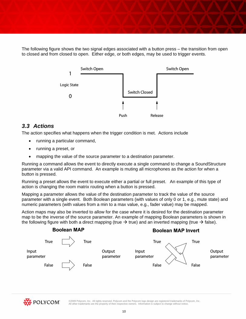
All the keys on the HDX remote may be used as sources of events. The individual keys are selected in an event by specifying a trigger that is equal to the key of interest. The entire set of key presses that may be defined are shown in the following figure (left) and the default key mappings that are created automatically are shown on the right.

©2009 Polycom, Inc. All rights reserved. Polycom and the Polycom logo design are registered trademarks of Polycom, Inc. All other trademarks are the property of their respective owners. Information is subject to change without notice.
20
As an example, consider the event for the adjusting the volume of the system. In this example, the trigger equals 59 which is the value of the volume up key on the remote. When key 59 is pressed, the fader for the amplifier will be incremented by 1dB.
©2009 Polycom, Inc. All rights reserved. Polycom and the Polycom logo design are registered trademarks of Polycom, Inc. All other trademarks are the property of their respective owners. Information is subject to change without notice.
21
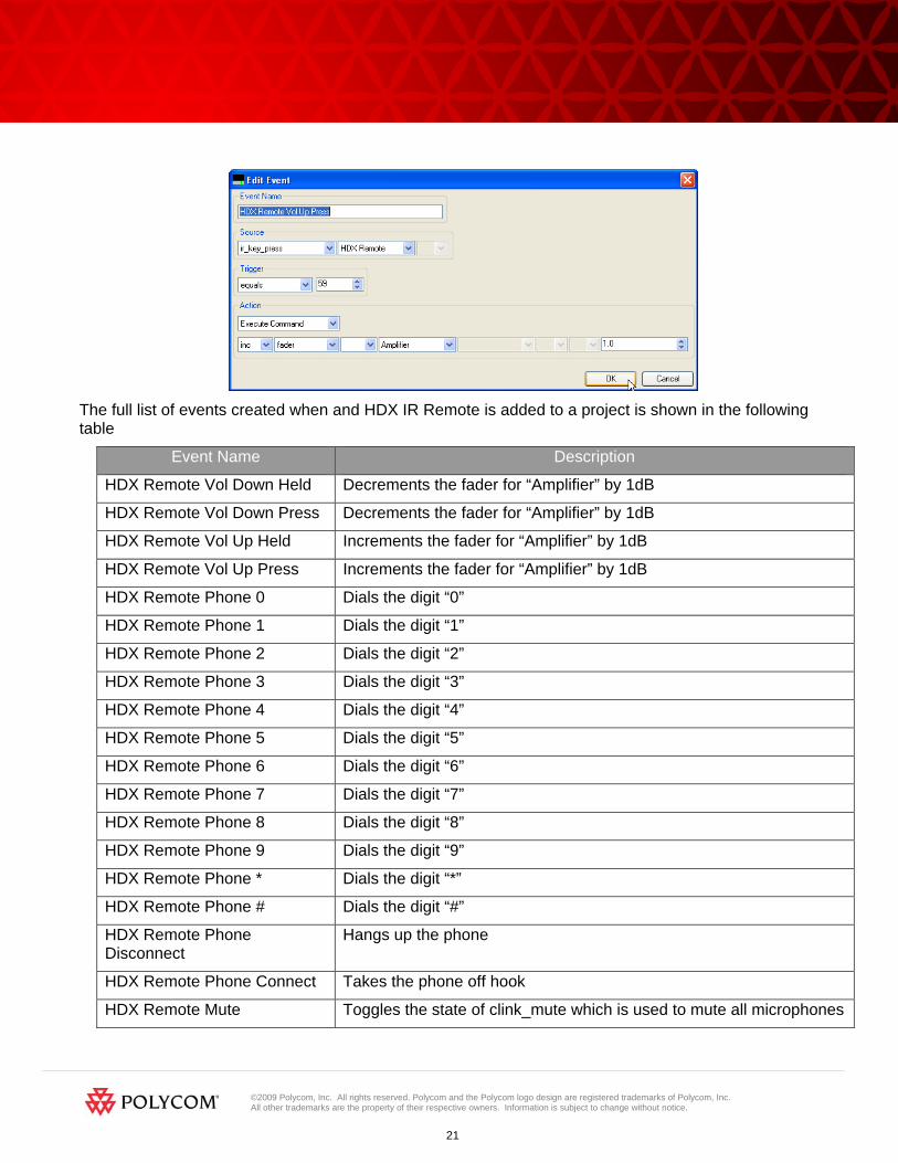
The full list of events created when and HDX IR Remote is added to a project is shown in the following table
Event Name Description
HDX Remote Vol Down Held Decrements the fader for “Amplifier” by 1dB
HDX Remote Vol Down Press Decrements the fader for “Amplifier” by 1dB
HDX Remote Vol Up Held Increments the fader for “Amplifier” by 1dB
HDX Remote Vol Up Press Increments the fader for “Amplifier” by 1dB
HDX Remote Phone 0 Dials the digit “0”
HDX Remote Phone 1 Dials the digit “1”
HDX Remote Phone 2 Dials the digit “2”
HDX Remote Phone 3 Dials the digit “3”
HDX Remote Phone 4 Dials the digit “4”
HDX Remote Phone 5 Dials the digit “5”
HDX Remote Phone 6 Dials the digit “6”
HDX Remote Phone 7 Dials the digit “7”
HDX Remote Phone 8 Dials the digit “8”
HDX Remote Phone 9 Dials the digit “9”
HDX Remote Phone * Dials the digit “*”
HDX Remote Phone # Dials the digit “#”
HDX Remote Phone Disconnect
Hangs up the phone
HDX Remote Phone Connect Takes the phone off hook
HDX Remote Mute Toggles the state of clink_mute which is used to mute all microphones

©2009 Polycom, Inc. All rights reserved. Polycom and the Polycom logo design are registered trademarks of Polycom, Inc. All other trademarks are the property of their respective owners. Information is subject to change without notice.
22
HDX Remote Preset Press Runs the preset “HDX Remote Preset”
The automatically generated events may be customized to suit a particular application and additional events for the other key presses on the HDX IR remote may be added by using the Add Events feature.
5.1 HDX Remote Channel ID SoundStructure Studio creates projects assuming the HDX IR remote has the default Channel ID of 3. Changing the default value from 3 to an alternative value may be done on the logic page by adjusting the knob of the channel ID from 0 to 15.
5.2 IR Receiver Connector To use an HDX IR remote transmitter, the SoundStructure system requires an IR receiver. Each SoundStructure device includes an IR receiver interface port that can be used with IR receivers from Xantech including models 780-80, 780-90, 480-00, 480-80, and 490-00. The IR receiver should be connected to the SoundStructure device using the pin out shown in the following figure.
The SoundStructure device supplies 12V so the receiver can be connected directly to the IR port on the SoundStructure device without an external power supply.
The wiring for the typical Xantech receiver is shown in the following figure.

©2009 Polycom, Inc. All rights reserved. Polycom and the Polycom logo design are registered trademarks of Polycom, Inc. All other trademarks are the property of their respective owners. Information is subject to change without notice.
23
6 Logic Ports Each SoundStructure device has two DB25 connectors where each DB25 connector has
• 11 logic inputs on each connector for a total of 22 logic inputs.
• 11 logic outputs on each connector for a total of 22 logic outputs
• One analog logic input on each connector for a total of two analog logic inputs
• One 5V supply on each connector for a total of two 5V supply pins
• One signal ground on each connector for a total of two signal grounds
The pin out of the rear panel DB25 connectors is shown in the figure.
Logic inputs have a value that is read as either 0 or 1, logic outputs have a value that is set to either 0 or 1, and the analog gain inputs have a value that will vary from 0 to 255. The details of how to use logic pins will be described in the following sections.

©2009 Polycom, Inc. All rights reserved. Polycom and the Polycom logo design are registered trademarks of Polycom, Inc. All other trademarks are the property of their respective owners. Information is subject to change without notice.
24
6.1 Digital Logic Inputs Logic inputs allow one to connect push to talk buttons and other dry contact1 closures to the rear panel of a SoundStructure device. The circuitry behind each logic input, shown in the following figure, shows that the logic inputs have a default value of 1 due to the internal pull-up resistor.
The logic inputs will have a default value of 1 (high) when the contact closure is open, and will have a value of 0 (low) when the contact closure is closed and tied to ground.
A typical contact closure example is shown in the following two figures. In the first figure, the input generates the value 1 (high) because the switch is open.
When the logic switch is closed, as shown in the figure below, the logic value will read the value 0 (low) indicating that the contact has been closed.
The logic inputs are internally debounced and can detect changes in the contact closures as short as 100msec.
6.2 Analog Logic Inputs The analog gain inputs (analog gain 1 and 2) operate by measuring an analog voltage between the analog input pin and the ground pin. The maximum input voltage level should not exceed +6 V. It is recommended that the +5 V supply on Pin 1 be used as the upper voltage limit.
An example of connecting a volume knob potentiometer for volume control is shown in the following figure. In this figure the volume knob will have three connections – one to the +5V connection, one to ground, and the third, the wiper of the potentiometer, will be connected to the analog gain input. As the knob is turned, the voltage measured will vary between 0 and approximately 5V. The values measured from the analog logic gain input will vary from approximately 0 to 255.
6.3 Logic Outputs
1 A dry contact closure is one where there is no voltage externally applied to the contacts – it is simply an open or closed circuit.
©2009 Polycom, Inc. All rights reserved. Polycom and the Polycom logo design are registered trademarks of Polycom, Inc. All other trademarks are the property of their respective owners. Information is subject to change without notice.
25
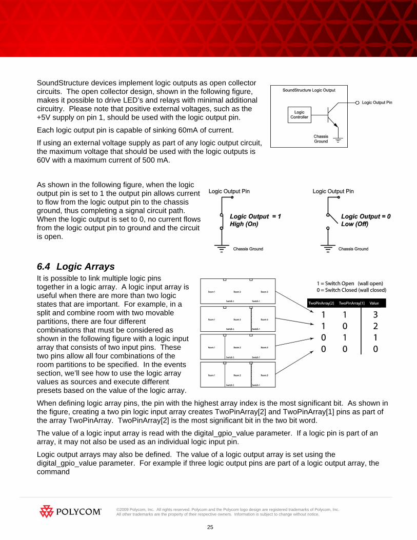
SoundStructure devices implement logic outputs as open collector circuits. The open collector design, shown in the following figure, makes it possible to drive LED’s and relays with minimal additional circuitry. Please note that positive external voltages, such as the +5V supply on pin 1, should be used with the logic output pin.
Each logic output pin is capable of sinking 60mA of current.
If using an external voltage supply as part of any logic output circuit, the maximum voltage that should be used with the logic outputs is 60V with a maximum current of 500 mA.
As shown in the following figure, when the logic output pin is set to 1 the output pin allows current to flow from the logic output pin to the chassis ground, thus completing a signal circuit path. When the logic output is set to 0, no current flows from the logic output pin to ground and the circuit is open.
6.4 Logic Arrays It is possible to link multiple logic pins together in a logic array. A logic input array is useful when there are more than two logic states that are important. For example, in a split and combine room with two movable partitions, there are four different combinations that must be considered as shown in the following figure with a logic input array that consists of two input pins. These two pins allow all four combinations of the room partitions to be specified. In the events section, we’ll see how to use the logic array values as sources and execute different presets based on the value of the logic array.
When defining logic array pins, the pin with the highest array index is the most significant bit. As shown in the figure, creating a two pin logic input array creates TwoPinArray[2] and TwoPinArray[1] pins as part of the array TwoPinArray. TwoPinArray[2] is the most significant bit in the two bit word.
The value of a logic input array is read with the digital_gpio_value parameter. If a logic pin is part of an array, it may not also be used as an individual logic input pin.
Logic output arrays may also be defined. The value of a logic output array is set using the digital_gpio_value parameter. For example if three logic output pins are part of a logic output array, the command
©2009 Polycom, Inc. All rights reserved. Polycom and the Polycom logo design are registered trademarks of Polycom, Inc. All other trademarks are the property of their respective owners. Information is subject to change without notice.
26
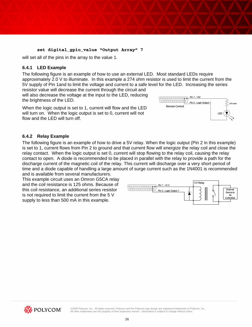
set digital_gpio_value “Output Array” 7
will set all of the pins in the array to the value 1.
6.4.1 LED Example The following figure is an example of how to use an external LED. Most standard LEDs require approximately 2.0 V to illuminate. In this example a 274 ohm resistor is used to limit the current from the 5V supply of Pin 1and to limit the voltage and current to a safe level for the LED. Increasing the series resistor value will decrease the current through the circuit and will also decrease the voltage at the input to the LED, reducing the brightness of the LED.
When the logic output is set to 1, current will flow and the LED will turn on. When the logic output is set to 0, current will not flow and the LED will turn off.
6.4.2 Relay Example The following figure is an example of how to drive a 5V relay. When the logic output (Pin 2 in this example) is set to 1, current flows from Pin 2 to ground and that current flow will energize the relay coil and close the relay contact. When the logic output is set 0, current will stop flowing to the relay coil, causing the relay contact to open. A diode is recommended to be placed in parallel with the relay to provide a path for the discharge current of the magnetic coil of the relay. This current will discharge over a very short period of time and a diode capable of handling a large amount of surge current such as the 1N4001 is recommended and is available from several manufacturers. This example circuit uses an Omron G5CA relay and the coil resistance is 125 ohms. Because of this coil resistance, an additional series resistor is not required to limit the current from the 5 V supply to less than 500 mA in this example.

©2009 Polycom, Inc. All rights reserved. Polycom and the Polycom logo design are registered trademarks of Polycom, Inc. All other trademarks are the property of their respective owners. Information is subject to change without notice.
27
7 Event Examples This section provides several examples of how to use events to customize a SoundStructure design.
7.1 Split and Combine Presets triggered from a logic input In this example, two presets are selected in the SoundStructure device, “Combine” and “Split”. The goal of this application is to have a logic input select which preset is executed based on the state of the logic switch.
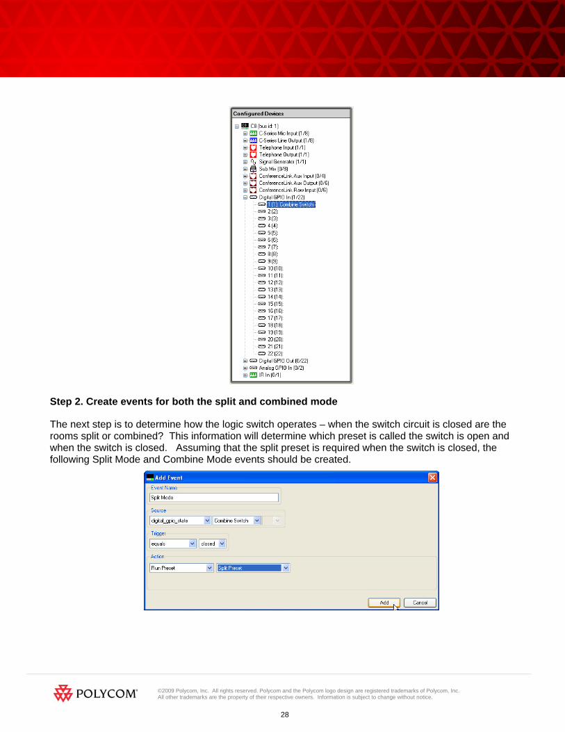
Step 1. Use the Edit Logic button to add a single Digital Logic Input. From the Events page select the Edit logic button and select a single digital logic input pin. Use a name for the pin that makes sense to you. In this example the pin is called “Combine Switch”
Next, check the logic inputs section of the wiring page and click and drag the logic input pin to the particular logic input pin that you would like to use if the default pin is not where the pin is physically wired.
©2009 Polycom, Inc. All rights reserved. Polycom and the Polycom logo design are registered trademarks of Polycom, Inc. All other trademarks are the property of their respective owners. Information is subject to change without notice.
28
Step 2. Create events for both the split and combined mode
The next step is to determine how the logic switch operates – when the switch circuit is closed are the rooms split or combined? This information will determine which preset is called the switch is open and when the switch is closed. Assuming that the split preset is required when the switch is closed, the following Split Mode and Combine Mode events should be created.

©2009 Polycom, Inc. All rights reserved. Polycom and the Polycom logo design are registered trademarks of Polycom, Inc. All other trademarks are the property of their respective owners. Information is subject to change without notice.
29
After adding these two events, the event page will show both events. From the events page is it easy to see that when the switch is closed the split preset will be run and when the switch is open the combined preset will be run. If it is determined once the switch is installed that the switch logic is reversed and the split preset should be called when the switch is open and the combined preset when the switch is closed, then the triggers or the actions may be easily reversed on the events. To edit an event, double click the event.
7.2 Push to Talk Microphones with LEDs In this example, the push to talk button on a microphone will be used to mute all microphones in room and the status LED on the microphone will be illuminated when the microphone is unmuted.
This example assumes that the microphone is already part of the system and now the logic inputs and outputs will be manually added to the existing system. If this is a new system, then use the logic input and logic output modes on the edit channels control to automatically add the logic inputs and outputs and events when the microphone inputs are defined.

©2009 Polycom, Inc. All rights reserved. Polycom and the Polycom logo design are registered trademarks of Polycom, Inc. All other trademarks are the property of their respective owners. Information is subject to change without notice.
30
7.2.1 Step 1: Add a logic input and output pin for each microphone. Use names for the logic pins that will make sense to you as you build your system. If you have many microphones, you may add multiple digital logic inputs and outputs by adjusting the quantity before clicking the add button.
7.2.2 Step 2: Create Mute Events on the button push In this example it was desired to have the mute state toggled on all microphones when the PTT button is pushed. To accomplish this we will create two events – one to toggle the clink_mute parameter and one to use clink_mute to mute “Mics”.
The first event “Toggle Clink Mute” will toggle the state of the clink_mute parameter on SoundStructure device 1. If there are multiple SoundStructure devices in the system, then additional events would be created to map clink_mute on device 1 to clink_mute on device 2 and so on to ensure the mute state is synced across multiple SoundStructure devices.
In this event, every time the PTT button is closed, the clink_mute parameter will be toggled.

©2009 Polycom, Inc. All rights reserved. Polycom and the Polycom logo design are registered trademarks of Polycom, Inc. All other trademarks are the property of their respective owners. Information is subject to change without notice.
31
To mute the microphonesbased on clink_mute, another event is required that will map clink_mute to the mute of the “Mics” group.
The Clink_mute to Mics Mute event take the clink_mute state of device 1 and maps that value to the mute state of the Mics group. Now whenever the PTT microphone button is pushed, the clink_mute parameter will toggle and any change in the clink_mute parameter will be mapped directly to the mute state of “Mics” causing all microphones in the “Mics” group to be muted.
7.2.3 Step 3: Create LED event based on the Mute state The final event required will map the mute state of the microphone to the LED state. In this example, it is desired to light the LED (logic output = 1) when the microphone is unmuted (mute = 0). To accomplish this we will use an invert in the map action as shown in the following figure.

©2009 Polycom, Inc. All rights reserved. Polycom and the Polycom logo design are registered trademarks of Polycom, Inc. All other trademarks are the property of their respective owners. Information is subject to change without notice.
32
The full set of events is shown on the Events page and appears as the figure shown below.
For each additional microphone that it is desired to add PTT logic, create additional Toggle Clink Mute and Table Mic Status LED events for each microphone. Only one “Clink_mute to Mics Mute” event is required.
7.3 Push and hold to temporarily mute a microphone In this example, a cough button is created to allow someone to mute their particular microphone while they are holding the button closed.
This example assumes that the microphone is already part of the system and now the logic inputs and outputs will be manually added to the existing system. If this is a new system, then use the logic input and logic output modes on the edit channels control to automatically add the logic inputs and outputs and associated events when the microphone input is defined.
7.3.1 Step 1: Add the logic input button. Use the edit logic button to add a digital logic input.

©2009 Polycom, Inc. All rights reserved. Polycom and the Polycom logo design are registered trademarks of Polycom, Inc. All other trademarks are the property of their respective owners. Information is subject to change without notice.
33
As with other examples, check the wiring page to confirm that the logic input is on the desired logic input pin.
7.3.2 Step 2. Create the event to map the button press to the mute state of the microphone Since the microphone should be muted (mute = 1) when the button is pressed (logic input = 0), the event should use an action map with the invert option as shown in the following figure. Anytime the button is pressed, the microphone will be muted. When the button is released, the microphone will be unmuted.
7.4 Phone Off hook drives a relay In this example, the status of the phone_connect parameter will be used to drive a logic output that is connected to a relay that can control an external circuit for illuminating a sign to indicate the phone is offhook.

©2009 Polycom, Inc. All rights reserved. Polycom and the Polycom logo design are registered trademarks of Polycom, Inc. All other trademarks are the property of their respective owners. Information is subject to change without notice.
34
7.4.1 Step 1. Add the logic output that will be used to drive the relay In this example, an analog logic output called “Phone Connect Status” was created.
7.4.2 Step 2: Create the Event In this example, the phone connect parameter is mapped to the logic output. If the phone is off hook (phone_connect = 1) then the logic output will allow current to flow and the relay will energize. The invert option is not necessary in this example.
7.5 Volume knob adjusts “Amplifier” fader In this example, a volume knob will be used to control volume of an output named “Amplifier”.

©2009 Polycom, Inc. All rights reserved. Polycom and the Polycom logo design are registered trademarks of Polycom, Inc. All other trademarks are the property of their respective owners. Information is subject to change without notice.
35
Step 1: Add the analog logic input
In this example a single Analog Logic Input was created and named this logic input Volume Knob.
Step 2: Create the event that will map the volume knob to the fader
In this example, the event maps the volume knob value to the fader of the “Amplifier” channel.
If there are user min and max fader limits set on the “Amplifier” channel, then those limits will be used automatically with the map event.

©2009 Polycom, Inc. All rights reserved. Polycom and the Polycom logo design are registered trademarks of Polycom, Inc. All other trademarks are the property of their respective owners. Information is subject to change without notice.
36
7.6 Gating information sent to a control system In this example, a logic output will be used to indicate that a particular microphone has gated on. When the gate status changes, the logic output will change and the SoundStructure system will send a command acknowledgement that could be used by a control system to indicate that a microphone has gated on.
Step 1: Add the Logic Output pin
In this example, a single logic output pin called “Mic 1 Gate” is created. Check the wiring page and the logic connections to a desired logic output pin if required.
Step 2: Create the event
Once the logic pin has been defined, an event mapping the microphone gating status to the logic output can be created.

©2009 Polycom, Inc. All rights reserved. Polycom and the Polycom logo design are registered trademarks of Polycom, Inc. All other trademarks are the property of their respective owners. Information is subject to change without notice.
37
In this example, when the Table Mic gates on the automixer, the logic output will be set to 1 and when the microphone gates off, the logic output will be set to 0.
When the microphone gates on, the SoundStructure system will send the acknowledgement: val digital_gpio_state "Mic 1 Gate" 1
when the microphone gates off, the following acknowledgement will be sent: val digital_gpio_state "Mic 1 Gate" 0
A control system can use the acknowledgements from the logic output pins to indicate on a touch panel that the particular microphone is gated on or off. If there are multiple microphones in a system, each microphone can have events that connect the microphone gating status to a different logic output pin.
7.7 Camera positioning with an HDX In this example, camera gating information will be used to send a command to a video codec over the serial interface of SoundStructure.
This example assumes that serial port on SoundStructure has been placed in broadcast mode. This may be configured from the wiring page as shown in the following figure.

©2009 Polycom, Inc. All rights reserved. Polycom and the Polycom logo design are registered trademarks of Polycom, Inc. All other trademarks are the property of their respective owners. Information is subject to change without notice.
38
This example shows that the ser_send command is used to send the serial command from the serial port on the SoundStructure with device ID 1. The command being sent is preset near go 1. The “\r” at the end of the command name represents a carriage return.
If an RS232 port is in the broadcast mode then that serial port cannot be used for controlling the SoundStructure system from an external control system or SoundStructure Studio.

©2009 Polycom, Inc. All rights reserved. Polycom and the Polycom logo design are registered trademarks of Polycom, Inc. All other trademarks are the property of their respective owners. Information is subject to change without notice.
39
8 Events Best Practices When creating SoundStructure events, the following recommendations will make it easier to use events
1. Define logic inputs and outputs before trying to use logic inputs or outputs with events
2. Confirm the wiring of the defined logic inputs and outputs matches the physical wiring to the DB25 connectors on SoundStructure devices. If necessary move logic pins definitions on the wiring page to match the physical wiring.
If logic pins are moved on the wiring page, save the project file to ensure the settings are stored permanently into the SoundStructure device.
3. Double check the source, trigger, and action to ensure the event does what you desire
4. Test logic inputs and events when working offline with SoundStructure Studio. Logic input pins may be forced to closed or open with set digital_gpio_state “logic pin” 0 command to close a switch or set digital_gpio_state “logic pin” 1 to open a switch. The name “logic pin” should be replaced by the name of the pin you are testing.
5. Use the event enable/disable option if it is necessary to isolate and test individual events
6. Select event names that are meaningful to make it easier to interpret the event list