Pololu Zumo 32U4 Robot User's Guide
76
Pololu Zumo 32U4 Robot User’s Guide View document on multiple pages. [https://www.pololu.com/docs/0J63] You can also view this document as a printable PDF [https://www.pololu.com/docs/pdf/0J63/zumo_32u4_robot.pdf]. Pololu Zumo 32U4 Robot User’s Guide © 2001–2015 Pololu Corporation https://www.pololu.com/docs/0J63/all Page 1 of 76
-
Upload
vuongnguyet -
Category
Documents
-
view
265 -
download
2
Transcript of Pololu Zumo 32U4 Robot User's Guide

Pololu Zumo 32U4 Robot User’sGuide
View document on multiple pages. [https://www.pololu.com/docs/0J63]You can also view this document as a printable PDF [https://www.pololu.com/docs/pdf/0J63/zumo_32u4_robot.pdf].
Pololu Zumo 32U4 Robot User’s Guide © 2001–2015 Pololu Corporation
https://www.pololu.com/docs/0J63/all Page 1 of 76

1. Overview . . . . . . . . . . . . . . . . . . . . . . . . . . . . . . . . . . . . . . . . . . . . . . . . . . . . 31.1. Configurations and included components . . . . . . . . . . . . . . . . . . . . . . . . . . . . . . . 41.2. What you will need . . . . . . . . . . . . . . . . . . . . . . . . . . . . . . . . . . . . . . . . . . . 81.3. Supported operating systems . . . . . . . . . . . . . . . . . . . . . . . . . . . . . . . . . . . . . 10
2. Contacting Pololu . . . . . . . . . . . . . . . . . . . . . . . . . . . . . . . . . . . . . . . . . . . . . . 113. The Zumo 32U4 in detail . . . . . . . . . . . . . . . . . . . . . . . . . . . . . . . . . . . . . . . . . . 12
3.1. Microcontroller . . . . . . . . . . . . . . . . . . . . . . . . . . . . . . . . . . . . . . . . . . . . 123.2. User interface . . . . . . . . . . . . . . . . . . . . . . . . . . . . . . . . . . . . . . . . . . . . . 123.3. Motors . . . . . . . . . . . . . . . . . . . . . . . . . . . . . . . . . . . . . . . . . . . . . . . . 143.4. Quadrature encoders . . . . . . . . . . . . . . . . . . . . . . . . . . . . . . . . . . . . . . . . . 153.5. Front sensor array (line and proximity sensors) . . . . . . . . . . . . . . . . . . . . . . . . . . . 173.6. Proximity sensing . . . . . . . . . . . . . . . . . . . . . . . . . . . . . . . . . . . . . . . . . . 183.7. Inertial sensors . . . . . . . . . . . . . . . . . . . . . . . . . . . . . . . . . . . . . . . . . . . . 213.8. Power . . . . . . . . . . . . . . . . . . . . . . . . . . . . . . . . . . . . . . . . . . . . . . . . . 223.9. Expansion areas . . . . . . . . . . . . . . . . . . . . . . . . . . . . . . . . . . . . . . . . . . . 233.10. Pin assignments . . . . . . . . . . . . . . . . . . . . . . . . . . . . . . . . . . . . . . . . . . . 253.11. Adding electronics . . . . . . . . . . . . . . . . . . . . . . . . . . . . . . . . . . . . . . . . . 283.12. AVR Timers . . . . . . . . . . . . . . . . . . . . . . . . . . . . . . . . . . . . . . . . . . . . . 303.13. Schematics and dimensions . . . . . . . . . . . . . . . . . . . . . . . . . . . . . . . . . . . . . 30
4. Assembling the Zumo 32U4 kit . . . . . . . . . . . . . . . . . . . . . . . . . . . . . . . . . . . . . . . 325. Programming the Zumo 32U4 . . . . . . . . . . . . . . . . . . . . . . . . . . . . . . . . . . . . . . . . 60
5.1. Installing Windows drivers . . . . . . . . . . . . . . . . . . . . . . . . . . . . . . . . . . . . . . 605.2. Programming using the Arduino IDE . . . . . . . . . . . . . . . . . . . . . . . . . . . . . . . . 625.3. Programming using avr-gcc and AVRDUDE . . . . . . . . . . . . . . . . . . . . . . . . . . . . 65
6. Zumo 32U4 Arduino library . . . . . . . . . . . . . . . . . . . . . . . . . . . . . . . . . . . . . . . . . 677. The Zumo 32U4 USB interface . . . . . . . . . . . . . . . . . . . . . . . . . . . . . . . . . . . . . . . 688. The A-Star 32U4 Bootloader . . . . . . . . . . . . . . . . . . . . . . . . . . . . . . . . . . . . . . . . 709. Reviving an unresponsive Zumo 32U4 . . . . . . . . . . . . . . . . . . . . . . . . . . . . . . . . . . . 73
9.1. Reviving using the Arduino IDE . . . . . . . . . . . . . . . . . . . . . . . . . . . . . . . . . . . 739.2. Reviving using AVRDUDE . . . . . . . . . . . . . . . . . . . . . . . . . . . . . . . . . . . . . 75
10. Related resources . . . . . . . . . . . . . . . . . . . . . . . . . . . . . . . . . . . . . . . . . . . . . . 76
Pololu Zumo 32U4 Robot User’s Guide © 2001–2015 Pololu Corporation
Page 2 of 76

1. Overview
The Zumo 32U4 robot is a complete, versatile robot controlled by an Arduino-compatible ATmega32U4microcontroller. When assembled, the low-profile tracked robot measures less than 10 cm on each side, makingit suitable for Mini-Sumo competitions.
At the heart of the Zumo 32U4 is an integrated ATmega32U4 AVR microcontroller from Atmel, along with dualH-bridge drivers that power the robot’s motors. The robot also features a variety of sensors, including quadratureencoders and inertial sensors (accelerometer and gyro) on the main board, along with reflectance and proximitysensors on the front sensor array. On-board pushbuttons offer a convenient interface for user input, and an LCD,buzzer, and indicator LEDs allow the robot to provide feedback.
Like our A-Star 32U4 programmable controllers [https://www.pololu.com/category/149/a-star-programmable-controllers], the Zumo 32U4 features a USB interface and ships preloaded with an Arduino-compatible bootloader.We provide a software add-on that makes it easy to program the Zumo 32U4 from the Arduino environment, aswell as a set of Arduino libraries to help interface with its on-board hardware.
Pololu Zumo 32U4 Robot User’s Guide © 2001–2015 Pololu Corporation
1. Overview Page 3 of 76

Comparison with the Zumo robot kit for Arduino (with Zumo Shield)Our older Zumo robot for Arduino [https://www.pololu.com/product/2510], built with a Zumo Shield[https://www.pololu.com/product/2508], is another Arduino-compatible robotic platform based on the Zumo chassis.The Zumo Shield is designed for a board with a standard Arduino form factor, like an Arduino Uno[https://www.pololu.com/product/2191], Arduino Leonardo [https://www.pololu.com/product/2192], or A-Star 32U4Prime [https://www.pololu.com/category/165/a-star-32u4-prime], to plug into it and act as its controller.
Assembled Zumo 32U4 robot.Assembled Zumo robot for Arduinowith an Arduino Uno (with original
white sprockets).
By contrast, the Zumo 32U4 includes an on-board ATmega32U4 microcontroller (the same one used in theLeonardo and A-Star 32U4 boards), combining the functions of the Zumo Shield and the separate Arduinocontroller into a single board and enabling the resulting robot to be even more compact. However, it remainsjust as easy to program as a standard Arduino, thanks to its USB interface and preloaded Arduino-compatiblebootloader. The Zumo 32U4 also adds many features that are not found on the Zumo Shield, including encoders,an LCD, and proximity detection.
Some of the pin mappings and software libraries differ between the Zumo 32U4 and Zumo robot for Arduino,so programs written for one robot generally need to be modified to work on the other.
1.1. Configurations and included componentsThe Zumo 32U4 robot is available in several configurations:
• Zumo 32U4 Robot Kit (No Motors) [https://www.pololu.com/product/3124] – requires assembly andsoldering; can be customized with your choice of motors [https://www.pololu.com/category/60/micro-metal-gearmotors] (not included)
• Zumo 32U4 Robot (assembled with 50:1 HP motors) [https://www.pololu.com/product/3125]
• Zumo 32U4 Robot (assembled with 75:1 HP motors) [https://www.pololu.com/product/3126]
• Zumo 32U4 Robot (assembled with 100:1 HP motors) [https://www.pololu.com/product/3127]
Pololu Zumo 32U4 Robot User’s Guide © 2001–2015 Pololu Corporation
1. Overview Page 4 of 76

Zumo 32U4 robot kit contentsThe kit version of the Zumo 32U4 robot includesthe following items:
• Zumo 32U4 main board and associatedhardware:
◦ two wide-angle and two narrow-anglethrough-hole infrared LEDs
◦ two 1×2 machine pin sockets for IR LEDs
◦ forward IR emitter LED holder
◦ two 3/16″ #2-28 thread-forming screws forLED holder
◦ buzzer [https://www.pololu.com/product/1484]
◦ 8×2 character LCD [https://www.pololu.com/product/356]
◦ 2×7 low-profile male header [https://www.pololu.com/product/2663] for LCD
◦ jumper wires (for soldering motors to the main board)
◦ two magnetic encoder discs [https://www.pololu.com/product/2599] (12 CPR)
• Zumo 32U4 front sensor array and associated hardware:◦ 2×12 female header and 2×12 extended male header for sensor array
◦ two 1×3 right-angle male headers and two shorting blocks – jumpers for sensor array
• Zumo chassis kit [https://www.pololu.com/product/1418], which includes:◦ Zumo chassis main body
◦ two drive sprockets
◦ two idler sprockets
◦ two 22-tooth silicone tracks
◦ two shoulder bolts with washers and M3 nuts
◦ four 1/4″ #2-56 screws and nuts
◦ battery terminals
• Zumo 32U4 blade• four 3/16″ #2-56 screws
• four additional #2-56 machine nuts (for a total of eight)
Pololu Zumo 32U4 Robot User’s Guide © 2001–2015 Pololu Corporation
1. Overview Page 5 of 76

Pololu Zumo 32U4 Robot User’s Guide © 2001–2015 Pololu Corporation
1. Overview Page 6 of 76

Pololu Zumo 32U4 Robot User’s Guide © 2001–2015 Pololu Corporation
1. Overview Page 7 of 76

Micro metal gearmotor withextended motor shaft.
The robot and chassis kit might include extra parts like jumper wires, screws, nuts, washers, andan acrylic spacer plate (which is not used in the Zumo 32U4), so do not be concerned if you havesome leftover hardware after assembling your Zumo. Your kit might also include a length of heatshrink tubing that can be used as shrouds for IR LEDs. Kits shipped before August 2015 includeheat shrink tubing but do not include the LED holder and its mounting screws.
Assembled Zumo 32U4 robotThe Zumo 32U4 robot is a complete, ready-to-program robot platform built from the samecomponents found in the Zumo 32U4 Robot Kit; nosoldering or assembly is required. A choice of threemotor gear ratios offer different combinations oftorque and speed.
Different versions of the assembled Zumo 32U4robots can be identified with a sticker on theunderside of the main board, visible inside thebattery compartment of the Zumo without batteriesinstalled. The color of the sticker indicates the gearratio of the robot’s motors:
• Green: 50:1 HP
• Blue: 75:1 HP
• Red: 100:1 HP
The assembled Zumo 32U4 robot is fitted with wide-angle IR emitter LEDs (clear); the narrow-angle LEDs (blue) are not included.
1.2. What you will needThese additional items are needed for using the Zumo 32U4 robot:
Pololu Zumo 32U4 Robot User’s Guide © 2001–2015 Pololu Corporation
1. Overview Page 8 of 76
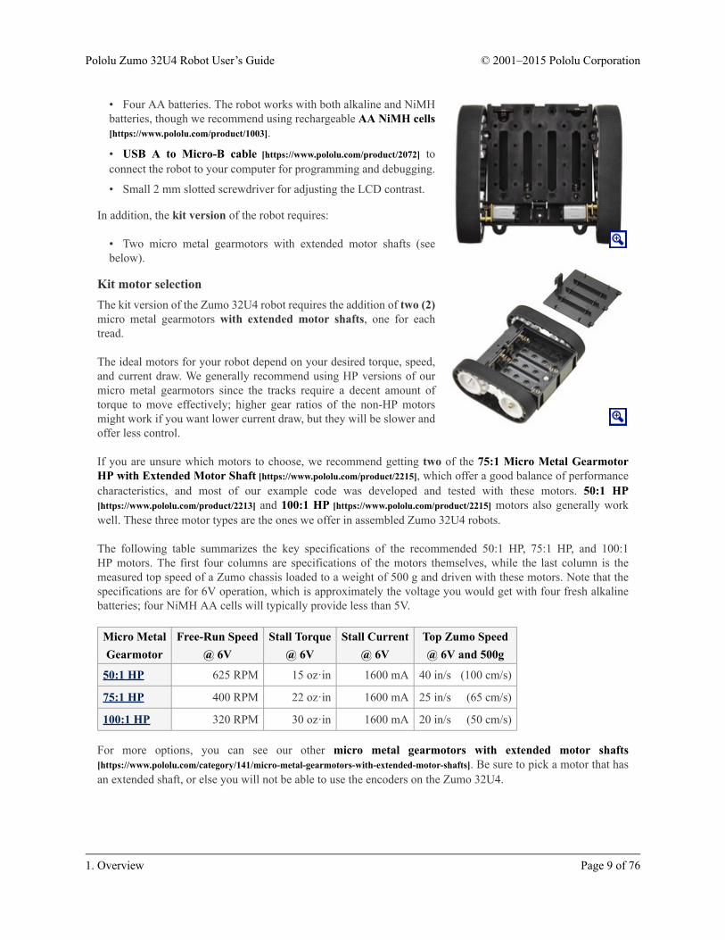
• Four AA batteries. The robot works with both alkaline and NiMHbatteries, though we recommend using rechargeable AA NiMH cells[https://www.pololu.com/product/1003].
• USB A to Micro-B cable [https://www.pololu.com/product/2072] toconnect the robot to your computer for programming and debugging.
• Small 2 mm slotted screwdriver for adjusting the LCD contrast.
In addition, the kit version of the robot requires:
• Two micro metal gearmotors with extended motor shafts (seebelow).
Kit motor selectionThe kit version of the Zumo 32U4 robot requires the addition of two (2)micro metal gearmotors with extended motor shafts, one for eachtread.
The ideal motors for your robot depend on your desired torque, speed,and current draw. We generally recommend using HP versions of ourmicro metal gearmotors since the tracks require a decent amount oftorque to move effectively; higher gear ratios of the non-HP motorsmight work if you want lower current draw, but they will be slower andoffer less control.
If you are unsure which motors to choose, we recommend getting two of the 75:1 Micro Metal GearmotorHP with Extended Motor Shaft [https://www.pololu.com/product/2215], which offer a good balance of performancecharacteristics, and most of our example code was developed and tested with these motors. 50:1 HP[https://www.pololu.com/product/2213] and 100:1 HP [https://www.pololu.com/product/2215] motors also generally workwell. These three motor types are the ones we offer in assembled Zumo 32U4 robots.
The following table summarizes the key specifications of the recommended 50:1 HP, 75:1 HP, and 100:1HP motors. The first four columns are specifications of the motors themselves, while the last column is themeasured top speed of a Zumo chassis loaded to a weight of 500 g and driven with these motors. Note that thespecifications are for 6V operation, which is approximately the voltage you would get with four fresh alkalinebatteries; four NiMH AA cells will typically provide less than 5V.
Micro MetalGearmotor
Free-Run Speed@ 6V
Stall Torque@ 6V
Stall Current@ 6V
Top Zumo Speed@ 6V and 500g
50:1 HP 625 RPM 15 oz·in 1600 mA 40 in/s (100 cm/s)
75:1 HP 400 RPM 22 oz·in 1600 mA 25 in/s (65 cm/s)
100:1 HP 320 RPM 30 oz·in 1600 mA 20 in/s (50 cm/s)
For more options, you can see our other micro metal gearmotors with extended motor shafts[https://www.pololu.com/category/141/micro-metal-gearmotors-with-extended-motor-shafts]. Be sure to pick a motor that hasan extended shaft, or else you will not be able to use the encoders on the Zumo 32U4.
Pololu Zumo 32U4 Robot User’s Guide © 2001–2015 Pololu Corporation
1. Overview Page 9 of 76

Kit assembly toolsThese additional items are needed for assembling the Zumo 32U4 robot kit:
• Soldering iron and solder (we recommend one with adjustable temperature control)
• Wire cutter
• Small #1 Phillips screwdriver
• 3 mm Allen wrench (hex key)
• long-nose pliers (for bending the IR LED leads and Zumo 32U4 blade mounting tabs)
• tape or small clamps (for holding parts together when soldering)
Additional optional componentsYou might also consider getting these for your Zumo 32U4 robot:
• Sensors [https://www.pololu.com/category/7/sensors], such as optical [https://www.pololu.com/category/79/sharp-distance-sensors] or sonar range finders [https://www.pololu.com/category/78/sonar-range-finders] (the Zumo 32U4already has built-in IR proximity sensors, but additional sensors can be incorporated for increased range ordetection area)
• Connectors and jumper wires [https://www.pololu.com/category/19/connectors], for connecting additionalsensors and components
• Battery charger, if you are using rechargeable batteries; since the Zumo just uses ordinary AA batteries,we recommend basic AA chargers (into which you stick the individual cells) available at most generalelectronics stores, though we carry a much fancier iMAX-B6AC V2 balance charger/discharger[https://www.pololu.com/product/2588] that can be also used for this
1.3. Supported operating systemsThe Zumo 32U4 robot can be programmed from a computer using any operating system that supports theArduino environment. This includes Microsoft Windows 10, 8.1, 8, 7, Vista, XP (with Service Pack 3), Linux,and Mac OS X.
Pololu Zumo 32U4 Robot User’s Guide © 2001–2015 Pololu Corporation
1. Overview Page 10 of 76

2. Contacting PololuWe would be delighted to hear from you about your experiences with the Zumo 32U4 robot. If you need technicalsupport or have any feedback you would like to share, you can contact us [https://www.pololu.com/contact] directlyor post on our forum [http://forum.pololu.com/viewforum.php?f=29]. Tell us what we did well, what we could improve,what you would like to see in the future, or anything else you would like to say!
Pololu Zumo 32U4 Robot User’s Guide © 2001–2015 Pololu Corporation
2. Contacting Pololu Page 11 of 76

3. The Zumo 32U4 in detail3.1. MicrocontrollerThe Zumo 32U4 main board features an integrated, USB-enabled ATmega32U4 AVR microcontroller fromAtmel, clocked by a precision 16 MHz crystal oscillator. This is the same microcontroller and clock frequencyused in our family of A-Star 32U4 programmable controllers [https://www.pololu.com/category/149/a-star-programmable-controllers], as well as the Arduino Leonardo [https://www.pololu.com/product/2192] and Micro[https://www.pololu.com/product/2188].
The main board includes a USB Micro-B connector that can be used to connect to a computer’s USB port viaa USB A to Micro-B cable [https://www.pololu.com/product/2072] (not included). The USB connection can be usedto transmit and receive data from the computer and program the board over USB. The USB connection alsoprovides power for the microcontroller and most of the other hardware on the Zumo (but not motor power); seeSection 3.8 for more details.
The Zumo’s ATmega32U4 comes preloaded with the same Arduino-compatible USB bootloader as the A-Star 32U4, which allows it to be easily programmed using the Arduino IDE. For more information aboutprogramming the Zumo 32U4, see Section 5. The ATmega32U4 might also come preloaded with a simpleprogram that blinks the yellow LED and writes “Zumo 32U4” to the LCD.
3.2. User interface
LEDsThe Zumo 32U4 has eight indicator LEDs.
• A yellow user LED is connected to Arduino digital pin 13, or PC7. You can drive this pin high in a userprogram to turn this LED on. The Zumo’s A-Star 32U4 Bootloader [https://www.pololu.com/docs/0J61/9] fadesthis LED on and off while it is waiting for a sketch to be loaded.
• A green user LED is connected to PD5 and lights when the pin is driven low. While the board is runningthe A-Star 32U4 Bootloader or a program compiled in the Arduino environment, it will flash this LEDwhen it is transmitting data via the USB connection.
• A red user LED is connected to Arduino pin 17, or PB0, and lights when the pin is driven low. Whilethe board is running the A-Star 32U4 Bootloader or a program compiled in the Arduino environment, it willflash this LED when it is receiving data via the USB connection.
Pololu Zumo 32U4 Robot User’s Guide © 2001–2015 Pololu Corporation
3. The Zumo 32U4 in detail Page 12 of 76

The Zumo32U4 library [https://www.pololu.com/docs/0J63/6] contains functions that make it easier to control thethree user LEDs. All three user LED control lines are also LCD data lines, so you will see them flicker when youupdate the LCD. The green and red user LEDs also share I/O lines with pushbuttons (see below).
• Two red LEDs on the left and right edges of the board indicate when the robot’s infrared emitters areactive on the corresponding side.
• Two blue power LEDs under the rear corners of the main board indicate when the robot is receivingpower from batteries (the power switch must be turned on). The left LED is connected to the reverse-protected and switched battery voltage (VBAT), while the right LED is connected to the output of the mainboard’s 5 V regulator.
The left blue LED will become noticeably dimmer as the total battery voltage drops below about3 V, and this can serve as an indication that a set of alkaline batteries has reached the end ofits useful life. However, rechargeable batteries can be damaged by overdischarge, so we do notrecommend allowing a set of four NiMH cells to discharge to this point. (A voltage divider isconnected to analog pin 1 and can be used to monitor the battery voltage; see Section 3.8 fordetails.)
• A green power LED under the center rear edge of the main board indicates when the USB bus voltage(VBUS) is present.
PushbuttonsThe Zumo 32U4 has four pushbuttons: a reset button on the right edge and three user pushbuttons locatedalong the rear edge of the main board. The user pushbuttons, labeled A, B, and C, are on Arduino pin 14 (PB3),PD5, and Arduino pin 17 (PB0), respectively. Pressing one of these buttons pulls the associated I/O pin to groundthrough a resistor.
The three buttons’ I/O lines are also used for other purposes: pin 14 is MISO on the SPI interface, PD5 and pin17 control the green and red user LEDs, and all three pins are LCD data lines. Although these uses require thepins to be driven by the AVR (or SPI slave devices in the case of MISO), resistors in the button circuits ensurethat the Zumo will not be damaged even if the corresponding buttons are pressed at the same time, nor will SPIor LCD communications be disrupted. The functions in the Zumo32U4 library [https://www.pololu.com/docs/0J63/6]take care of configuring the pins, reading and debouncing the buttons, and restoring the pins to their originalstates.
LCDThe Zumo 32U4 has a 2×7 header where you can connect the included 8×2 character LCD[https://www.pololu.com/product/356] (or any other LCD with the common HD44780 parallel interface[https://www.pololu.com/file/download/DMC50448N-AAE-AD.pdf?file_id=0J71] (109k pdf)). You can adjust the LCDcontrast with the potentiometer to the left of the LCD connector. We recommend using a 2 mm slottedscrewdriver to adjust the contrast.
The Zumo32U4 library [https://www.pololu.com/docs/0J63/6] provides functions to display data on a connectedLCD. It is designed to gracefully handle alternate use of the LCD data lines by only changing pin states whenneeded for an LCD command, after which it will restore them to their previous states. This allows the LCD datalines to be used for other functions (such as pushbutton inputs and LED drivers).
Pololu Zumo 32U4 Robot User’s Guide © 2001–2015 Pololu Corporation
3. The Zumo 32U4 in detail Page 13 of 76

BuzzerThe buzzer [https://www.pololu.com/product/1484] on the Zumo 32U4 can be used to generate simple sounds andmusic. By default, it is connected to digital pin 6 (which also serves as OC4D, a hardware PWM output fromthe AVR’s 10-bit Timer4). If you alternate between driving the buzzer pin high and low at a given frequency, thebuzzer will produce sound at that frequency. You can play notes and music with the buzzer using functions inthe Zumo32U4Buzzer library. If you want to use pin 6 for an alternate purpose, you can disconnect the buzzercircuit by cutting the surface-mount jumper next to the buzzer.
3.3. MotorsTwo on-board Texas Instruments DRV8838 motor drivers power the Zumo 32U4’s two micro metal gearmotors.Four Arduino pins are used to control the drivers:
• Digital pin 15, or PB1, controls the right motor direction (LOW drives the motor forward, HIGHdrives it in reverse).
• Digital pin 16, or PB2, controls the left motor direction.
• Digital pin 9, or PB5, controls the right motor speed with PWM (pulse width modulation) generatedby the ATmega32U4’s Timer1.
• Digital pin 10, or PB6, controls the left motor speed with PWM.
For more information about the drivers, see the DRV8838 datasheet [https://www.pololu.com/file/download/drv8838.pdf?file_id=0J806] (1MB pdf). We also sell a carrier board [https://www.pololu.com/product/2990] for thisdriver.
The Zumo32U4 library [https://www.pololu.com/docs/0J63/6] provides functions that allow you to easily control themotors, and it can optionally take care of flipping a direction signal for you if you accidentally soldered in amotor backwards.
As your batteries run out, the voltage supplied to the motor drivers (VBAT) will decrease, whichwill make the motors slower. It is possible to account for this in your code by monitoring thebattery voltage (see Section 3.8) or using the encoders and other sensors to monitor the movementof the robot.
Pololu Zumo 32U4 Robot User’s Guide © 2001–2015 Pololu Corporation
3. The Zumo 32U4 in detail Page 14 of 76

3.4. Quadrature encodersEach drive motor on the Zumo 32U4 has acorresponding quadrature encoder system consistingof a magnetic disc attached to the extended motorshaft and a pair of Hall effect sensors mounted to theunderside of the main board. Other than the sensororientation, these encoders work similarly to ourmagnetic encoder kits for micro metalgearmotors [https://www.pololu.com/product/2598].They can be used to track the rotational speed anddirection of the robot’s drive sprockets.
The encoders provide a resolution of 12 counts perrevolution of the motor shaft when counting bothedges of both channels. To compute the counts perrevolution of the drive sprockets, multiply thegearboxes’ gear ratio by 12. For example, if 75:1motors [https://www.pololu.com/product/2215] (whichhave gear ratios more accurately specified as75.81:1) are used, the encoders provide 75.81 × 12 ≈ 909.7 CPR.
Quadrature encoder transitions are often detected by monitoring both encoder channels directly. However, sincetransitions on the Zumo’s encoders can occur at high frequencies (several thousand per second) when its motorsare running, it is necessary to use the AVR’s pin change interrupts or external interrupts to read the encoders. Toreduce the required number of interrupt pins, the Zumo 32U4 main board XORs together both channels of eachencoder and connects the resulting signal to an interrupt pin, while channel B of each encoder is connected to anon-interrupt pin:
• Digital pin 7, or PE6, reads the right encoder XORed signal using external interrupt INT6.
• Digital pin 8, or PB4, reads the left encoder XORed signal using pin change interrupt PCINT4.
• Digital pin 23 (analog pin 5), or PF0, reads the right encoder channel B.
• Pin PE2 reads the left encoder channel B.
Pololu Zumo 32U4 Robot User’s Guide © 2001–2015 Pololu Corporation
3. The Zumo 32U4 in detail Page 15 of 76

The XORed signal and the channel B signal can be used to reconstruct the channel A signal by simply XORingthem again: (A XOR B) XOR B = A. For both encoders, channel A leads channel B when the motor is rotatingin the forward direction; that is, A rises before B rises and A falls before B falls. (The waveforms in the diagramabove would be produced by forward rotation.)
The Zumo 32U4 library [https://www.pololu.com/docs/0J63/6] provides appropriate interrupt service routines andfunctions for reading the encoders and keeping track of their counts.
Pololu Zumo 32U4 Robot User’s Guide © 2001–2015 Pololu Corporation
3. The Zumo 32U4 in detail Page 16 of 76

3.5. Front sensor array (line and proximity sensors)The Zumo 32U4 Front Sensor Array is a separateboard that attaches to the main board. The boardfeatures five line sensors and three proximitysensors, though by default, you can only have six ofthese eight sensors connected to the Zumo’smicrocontroller at any given time.
The five line sensors face downward and can helpthe Zumo distinguish between light and darksurfaces. They can also be used to detect sources ofinfrared light, like the sun. Each reflectance sensorconsists of a down-facing infrared (IR) emitter LEDpaired with a phototransistor that can detectreflected infrared light from the LED. Thereflectance sensors operate on the same principles asour QTR-1RC [https://www.pololu.com/product/2459]sensor: the AVR uses an I/O line to drive the sensoroutput high, and then measures the time for theoutput voltage to decay. The IR emitters for thereflectance sensors are on by default, but they can beturned off by driving digital pin 11 low. The five line sensors are numbered 1 through 5, with line sensor 1 beingthe robot’s left-most sensor. In schematics and diagrams, they are referred to as DOWN1, DOWN2, DOWN3,DOWN4, and DOWN5. On the front sensor array, their signals are labeled DN1, DN2, DN3, DN4, and DN5. Thepart used for the line sensors is the Sharp GP2S60 compact reflective photointerrupter[https://www.pololu.com/file/download/GP2S60_DS.pdf?file_id=0J683] (164k pdf).
The three proximity sensors face in different directions away from the Zumo and can help detect nearby objects.They can also be used to detect commands from typical IR remote controls. The proximity sensors, like the linesensors, detect reflected IR light, but they are designed to only detect light that is turned on and off quickly at afrequency of 38 kHz. To read a proximity sensor, the AVR can enable the internal pull-up on the correspondingI/O line. When the sensor is active, it will drive the line low. The proximity sensors do not have IR emitterspaired with them; instead they detect reflected 38 kHz IR light that comes from LEDs on the Zumo 32U4 MainBoard, which are described in Section 3.6. The proximity sensors are named after the directions they face: left,right, or front. In schematics and diagrams, they are referred to as LEFT, RIGHT, and FRONT. On the frontsensor array, their signals are labeled LFT, FRONT, and RGT. The part used for the proximity sensors is theVishay TSSP77038 IR receiver module [https://www.pololu.com/file/download/tssp77038.pdf?file_id=0J615] (268k pdf).The TSSP77038 has a fixed gain (sensitivity) that makes the sensor more predictable.
Each sensor output on the front sensor array is protected by a 220 Ohm resistor to help prevent short circuitswhen the AVR is driving the corresponding I/O line.
The infrared emitted by the line sensors can interfere with the proximity sensors and cause false readings,so it is recommended to turn off the line sensor emitters before using the proximity sensors. TheZumo32U4ProximitySensors class from the Zumo 32U4 Arduino library takes care of turning off the line sensoremitters.
Pin assignmentsBy default, the front sensor array supports these pin assignments:
Pololu Zumo 32U4 Robot User’s Guide © 2001–2015 Pololu Corporation
3. The Zumo 32U4 in detail Page 17 of 76

• Pin A0 (18) is connected to line sensor 1 (DN1),
• Pin A3 (21) is connected to line sensor 3 (DN3).
• Pin 12 is connected to line sensor 5 (DN5).
• Pin A4 (22) is connected to the front proximity sensor.
• Pin A2 (20) is connected to either the left proximity sensor (LFT) or line sensor 2 (DN2), depending onthe position of a jumper.
• Pin 4 is connected to either the right proximity sensor (RGT) or line sensor 4 (DN4), depending on theposition of a jumper.
• Pin 11 is connected to the line sensor emitter control pin (LEDON).
The assembled versions of the Zumo 32U4 robot ship with jumpers selecting the left (LFT)and right (RGT) proximity sensors instead of down-facing DN2 and DN4, so these versions areconfigured for three down-facing sensors and all three proximity sensors by default.
The signals from the sensors can be remapped by soldering in a wire from the signal output to the desired I/Opin. You would also want to disconnect the sensor output from the standard I/O pin so that pin can be used forother purposes. For line sensor 1, line sensor 3, line sensor 5, and the front proximity sensor, disconnecting thesensor involves cutting a trace between the signal output and the standard I/O pin, which is labeled on the board.For the line sensor 2, line sensor 4, the left proximity sensor, and the right proximity sensor, you can simplymove or remove the corresponding jumper.
Example remapping: using all the sensorsIf you want to use all five line sensors and all three proximity sensors in one application, you can accomplishthat by freeing up two I/O lines and remapping two of the pins. One way to accomplish this is by removing theZumo’s LCD to free up pins 0 and 1. Next, configure the jumpers on the front sensor array to connect pin 4to line sensor 4, and pin 20 to line sensor 2. Solder a wire from the right proximity sensor signal to pin 0, andsolder a wire from the left proximity sensor to pin 1. You will need to modify your code to include the new pinassignments, and you should remove all LCD-related code.
3.6. Proximity sensingThe Zumo 32U4 can detect nearby objects using the three proximity sensors on the front sensor array. Theproximity sensors do not emit their own light; instead they are designed to detect 38 kHz infrared (IR) signalsfrom emitters on the Zumo 32U4 Main Board.
The main board has four IR emitters:
• The middle-left and middle-right IR LEDs are surface-mounted on either side of the Zumo, inside thetracks and between the wheels. They emit light to the left and to the right.
• The front-left and front-right IR LEDs are meant to face towards the front, though you can play with theexact angle to see if it yields better results for your particular application. These LEDs are included, butthey must be installed by the user, as described in Section 4.
Pololu Zumo 32U4 Robot User’s Guide © 2001–2015 Pololu Corporation
3. The Zumo 32U4 in detail Page 18 of 76

The middle-left LED and the front-left LED are in series, so you must install the front-left LEDin order to use the middle-left LED, and you cannot turn on one without turning on the other.Similarly, the middle-right and front-right IR emitters are in series.
Two AVR pins are used to control the LEDs: pin 5 (OC3A) is the proximity LED PWM pin, and must be drivenhigh to turn on any of the LEDs. Pin A1 (19) is the proximity LED selection pin, and must be driven high orlow to select which set of LEDs to turn on. If A1 is high, the right-side LEDs are selected. If A1 is low, theleft-side LEDs are selected. (When A1 is an input, it can be used to read the battery voltage.) The brightness ofthe emitters can be controlled by adjusting the duty cycle of the PWM signal on pin 5.
Our example code operates the proximity sensors by transmitting pulses on both the left and right LEDs at sixdifferent brightness levels. For each sensor, it generates two numbers: the number of brightness levels for theleft LEDs that activated the sensor, and the number of brightness levels for the right LEDs that activated thesensor. A higher reading corresponds to more IR light getting reflected to the sensor, which is influenced by thesize, reflectivity, proximity, and location of nearby objects. However, the presence of other sources of 38 kHz IRpulses (e.g. from another robot) can also affect the readings.
You can also just read the proximity sensors without turning on any LEDs. This could allow the Zumo to detectthe IR proximity sensors of other robots, or to detect commands from a typical IR remote.
Forward LED selection
The kit version of the Zumo 32U4 comes with two types of through-hole IR LEDs that can be installed toserve as the forward emitters. Both types of LEDs use the T-1 3/4 package, meaning they have a diameterof approximately 5 mm. Also, they both emit 940 nm light. The main difference between these LEDs is theirviewing angle. The blue-colored LEDs have a relatively narrow viewing angle of 20°, which makes them betterat illuminating objects far away. The clear LEDs have a much wider 50° viewing angle, which makes them betterat illuminating objects that are not directly in front of the Zumo. The choice of IR LEDs to use is one way foryou to customize your Zumo.
The assembled versions of the Zumo 32U4 robot ship with clear (wide-angle) LEDs installed; blue (narrow-angle) LEDs are not included with these versions.
Pololu Zumo 32U4 Robot User’s Guide © 2001–2015 Pololu Corporation
3. The Zumo 32U4 in detail Page 19 of 76

IR LED holder
Note: Kits shipped before August 2015 do not include the LED holder and its mounting screws.Instead, the forward IR emitter LEDs can be shielded with shrouds made from the included heatshrink tubing as described below.
Proper shielding for the forward emitters is important; without shielding, light from the LEDs can activate theproximity sensors directly and cause false readings. The Zumo 32U4 comes with a plastic LED holder that servesto shield the LEDs while also holding them in place and helping to protect them from collisions with otherrobots. The LED holder screws to the blade with the two included 3/16″ #2-28 thread-forming screws. See theassembly instructions in Section 4 to learn how to properly install the forward emitters with the LED holder.
IR LEDs with LED holder.
Shielding with heat shrink tubingYou can make shrouds out of black heat shrink tubing to shield the forward emitters as an alternative to using theLED holder. Without the LED holder, the LEDs are less securely mounted, but you can more easily adjust theirpositioning.
IR LEDs with heat shrink shielding.
You can test to see if your shielding is good by putting your Zumo on a black surface with no objects nearby andmaking sure that you get a reading of 0 for all the proximity sensors.
3/16″ diameter heat shrink tubing can work well (tubing of this size was included with kits prior to August2015), but please note that the actual diameter of heat shrink tubing often differs significantly from its nominaldiameter, depending on the type and manufacturer of the tubing.
Pololu Zumo 32U4 Robot User’s Guide © 2001–2015 Pololu Corporation
3. The Zumo 32U4 in detail Page 20 of 76

Proximity sensor performanceThe proximity sensors have no particular minimum sensing distance; they can sense an object that is close to theZumo as long as the shape of that object allows some light from the LEDs to be reflected into the sensor.
The maximum sensing distance depends on the size and reflectivity of the object you are sensing. We did severaltests of the front proximity sensors to see how well they could see the steel blade of another Zumo while bothrobots were on the black surface of a sumo ring. In these tests, we found that the maximum sensing distance wasaround 30 cm to 40 cm.
There is a significant dead spot between the sensing regions of the front sensor and each side sensor. Therefore,if the Zumo senses an object with the left or right sensors and then turns to face it, there will probably be a periodof time where none of the sensors can see the object.
Facing towards an objectThe FaceTowardsOpponent demo found in the Zumo 32U4 Arduino library (Section 6) uses the motors and thefront proximity sensor to scan for nearby objects, face directly towards them, and track them if they move. Todirectly face an object, it compares the two readings from the front sensor: the number of brightness levels forthe left LEDs that resulted in the sensor activating, and the number of brightness levels for the right LEDs thatresulted in the sensor activating. If the left reading is greater than the right reading, it means the object is closerto the left LEDs, so the robot should turn left (counter-clockwise) to face it more directly. Similarly, if the rightreading is greater than the left reading, the robot should turn right (clockwise). If both of the readings are belowa certain threshold, then it just turns the motors in order to scan for nearby objects.
This could be a good starting point for a sumo robot that uses the front sensors to locate its opponent.
3.7. Inertial sensorsThe Zumo 32U4 includes on-board inertial sensors that can be used in advanced applications, such as helpingyour Zumo detect collisions and determine its own orientation by implementing an inertial measurementunit (IMU). The first chip, an ST LSM303D [https://www.pololu.com/product/2127] compass module, combines a3-axis accelerometer and 3-axis magnetometer into a single package. The second chip is an ST L3GD20H[https://www.pololu.com/product/2129] 3-axis gyroscope. Both sensor chips share an I²C bus connected to theATmega32U4’s I²C interface.
Level shifters built into the main board allow the inertial sensors, which operate at 3.3 V, to be connected to theATmega32U4 (operating at 5 V). The sensors, level shifters, and I²C pull-up resistors are connected to the SDA(digital pin 2, or PD1) and SCL (digital pin 3, or PD0) pins on the AVR by default, but they can be disconnectedby cutting the surface-mount jumpers labeled “2 = SDA” and “3 = SCL” on the board to allow those pins to beused for other purposes.
We recommend carefully reading the LSM303D datasheet [https://www.pololu.com/file/download/LSM303D.pdf?file_id=0J703] (1MB pdf) and L3GD20H datasheet [https://www.pololu.com/file/download/L3GD20H.pdf?file_id=0J731] (3MB pdf) to understand how these sensors work and how to use them.
Using the sensorsThe Zumo32U4 library [https://www.pololu.com/docs/0J63/6] includes functions that make it easier to work withthe sensors, as well as some example programs that demonstrate how to use them. (The software interface isidentical to those of our LSM303 Arduino library [https://github.com/pololu/lsm303-arduino] and L3G Arduinolibrary [https://github.com/pololu/l3g-arduino].)
Pololu Zumo 32U4 Robot User’s Guide © 2001–2015 Pololu Corporation
3. The Zumo 32U4 in detail Page 21 of 76

In addition, the sensor ICs on the Zumo 32U4 are the same as those on our MinIMU-9 v3[https://www.pololu.com/product/2468], so Arduino software written for the MinIMU-9 (such as our AHRS example[https://github.com/pololu/minimu-9-ahrs-arduino]) can also be adapted to work on a Zumo 32U4 robot.
Notes on the magnetometerPlease note that the magnetometer in the LSM303 is affected by currents in the motors and buzzer when theyare operating, as well as metal in the batteries, and the readings are easily influenced by magnetic distortions inthe environment around the Zumo (such as rebar in a concrete floor). As a result, it is very hard to accuratelydetermine the Zumo’s absolute heading based on the magnetometer data. However, in our tests, we found that themagnetometer could still be useful for rough measurements of relative orientation changes; for example, oncethe magnetic readings are compensated for a particular environment, they can be used to help the Zumo turn leftor right by a specific angle instead of just timing how long to run the motors to make such a turn (although thegyro or encoders might be better suited for this particular purpose).
In our tests, we found that the batteries, motors, and motor current affect the z axis of themagnetometer much more strongly than the x and y axes, so you probably will want to ignorethe z readings. We were generally able to get decent results using only the x and y magnetometerreadings to determine heading. Additionally, you might need to decrease the magnetometersensitivity; if the magnetometer returns a value of -4096, that is a sign that the sensitivity range isset too narrow for your particular environment.
3.8. PowerThe Zumo chassis has an internal compartment for four AA batteries. We recommend using rechargeable AANiMH cells [https://www.pololu.com/product/1003], which results in a nominal voltage of 4.8 V (1.2 V per cell). Youcan also use alkaline cells, which would nominally give you 6 V.
The negative battery voltage is connected to GND. The positive battery voltage is designated VB. VB feeds intoa circuit that provides reverse protection and power switching controlled by the on-board power switch. Theoutput of this circuit is designated VBAT.
VBAT provides power to the motors through the DRV8838 motor drivers, so the motors can only operate if thebatteries are installed and the power switch is in the “On” position.
The battery voltage on VBAT can be monitored through a voltage divider that is connected to analog pin 1(PF6) by default. The divider outputs a voltage that is equal to one half of the battery voltage, which will besafely below the ATmega32U4’s maximum analog input voltage of 5 V as long as the battery voltage is less than10 V. The readBatteryMillivolts() function in the Zumo32U4 library [https://www.pololu.com/docs/0J63/6] canbe used to determine the battery voltage from this reading. The surface-mount jumper labeled “A1 = VBAT/2”can be cut to disconnect the voltage divider and free the pin for other uses.
5V regulatorVBAT supplies power to a 5V regulator based on the TPS63061 switching step-up/step-down (buck-boost)converter from Texas Instruments. The regulator works with a 2.7 V to 11.8 V input voltage (although themotor drivers limit the maximum operating voltage of the Zumo 32U4 to 11 V) and has a typical efficiencyof 80% to 90% for most combinations of input voltage and load. (We also make a standalone regulator[https://www.pololu.com/product/2119] based on this integrated circuit.) The 5V output of this regulator is designatedVREG.
Pololu Zumo 32U4 Robot User’s Guide © 2001–2015 Pololu Corporation
3. The Zumo 32U4 in detail Page 22 of 76

The regulator can be disabled by driving the regulator shutdown pin, SHDN, high.
Power selectionThe Zumo 32U4 main board’s power selection circuit uses the TPS2113A power multiplexer[https://www.pololu.com/product/2596] from Texas Instruments to choose whether its 5 V logic supply (designated5V) is sourced from USB or the batteries via the regulator, enabling the robot to safely and seamlessly transitionbetween the two sources. The TPS2113A is configured to select regulated battery power (VREG) unless theregulator output falls below about 4.5 V. If this happens, it will select the higher of the two sources, which willtypically be the USB 5 V bus voltage if the Zumo is connected to USB.
Consequently, when the Zumo 32U4 is connected to a computer via USB, it will receive 5 V logic power evenwhen the power switch is off. This can be useful if you want to upload or test a program without drawing powerfrom the batteries and without operating the motors. It is safe to have USB connected and battery power switchedon at the same time.
The currently selected source is indicated by the STAT pin; this pin is an open-drain output that is lowif the batteries are selected and high-impedance if the USB supply is selected. The current limit of theTPS2113A is set to about 1.9 A. For more information about the power multiplexer, see the TPS2113Adatasheet [https://www.pololu.com/file/download/tps2113a.pdf?file_id=0J771] (1MB pdf).
3.3V regulatorThe main board also has 3.3 V linear regulator. The inertial sensors draw power from the 3.3 V line; theremainder (up to a few hundred milliamps) is available for powering external circuits or devices.
Alternative power sourcesFor users who want to experiment with alternative power sources like lithium batteries, the Zumo 32U4 canaccept a battery input voltage from 2.7 V to 10 V. You can raise the maximum allowable voltage to the motordrivers’ limit of 11 V by disconnecting or modifying the battery voltage divider.
We do not recommend using a 3-cell lithium battery to power the Zumo 32U4. Even though sucha battery is usually specified with a nominal voltage of 11.1 V, it can measure well over 12 Vwhen fully charged.
Adding a power switchYou can add your own power switch to the Zumo 32U4 using the PSW pin. When it is in the on position, yourswitch should connect PSW to GND. In that case, VBAT will receive power when either your switch or the mainboard switch are on.
3.9. Expansion areasThe top expansion areas on the Zumo 32U4 main board (in two 2×13 groups of pins near the left and right edges)break out all of the ATmega32U4 microcontroller’s general-purpose I/O lines and provide access to variouspower inputs and outputs. Some of these pins are also broken out in the front expansion area, where the frontsensor array connects. The following diagrams identify the locations of these pins and the hardware associatedwith them.
Pololu Zumo 32U4 Robot User’s Guide © 2001–2015 Pololu Corporation
3. The Zumo 32U4 in detail Page 23 of 76

Zumo 32U4 top expansion pinout.
Pololu Zumo 32U4 Robot User’s Guide © 2001–2015 Pololu Corporation
3. The Zumo 32U4 in detail Page 24 of 76

Zumo 32U4 front expansion and LCD connector pinout.
These diagrams are also available as a printable PDF [https://www.pololu.com/file/download/zumo-32u4-pinout.pdf?file_id=0J864] (536k pdf). For more information about the ATmega32U4 microcontroller andits peripherals, see Atmel’s ATmega32U4 documentation.
3.10. Pin assignmentsThe table below lists the most important pin assignments for the ATmega32U4 on the Zumo 32U4. This table ishelpful if you want to add your own electronics to the Zumo 32U4, write your own low-level code for interfacingwith the hardware, or just want to understand better how the Zumo 32U4 works. Each row represents a physicalpin on the ATmega32U4.
The “ATmega32U4 pin name” column shows the official name of the pin according to the ATmega32U4datasheet [http://www.atmel.com/devices/atmega32u4.aspx].
The “Arduino pin names” column lists the names provided by the Arduino environment for the pin. These namescan generally be used as arguments to any function that takes a pin number. However, there are some exceptions.For example, passing the number 4 to analogRead actually reads pin A4, not pin 4. Also, due to hardwarelimitations, some functions only work on a limited set of pins.
The “Zumo 32U4 functions” column documents what the pin is used for on the Zumo 32U4. Many pins canserve multiple purposes concurrently by switching modes. For example, PB0 can read the state of button C whenit is an input, and it can control the red LED and serve as an LCD data line when it is an output.
Pololu Zumo 32U4 Robot User’s Guide © 2001–2015 Pololu Corporation
3. The Zumo 32U4 in detail Page 25 of 76

The “Note/alternate functions” column documents other features of the pin, although some of those featuresmight be impractical to use.
Pololu Zumo 32U4 Robot User’s Guide © 2001–2015 Pololu Corporation
3. The Zumo 32U4 in detail Page 26 of 76

ATmega32U4pin name
Arduinopin names Zumo 32U4 functions Notes/alternate functions
PB7 11 Line sensor IR LED control
Timer0 PWM output A (OC0A)Timer1 PWM output C (OC1C)UART flow control (RTS)Pin-change interrupt (PCINT7)
PF7 A0, 18 Line sensor 1 (leftmost) Analog input (ADC7)JTAG test data in (TDI)
PF5 A2, 20Line sensor 2Left proximity sensor(function selected by jumper)
Analog input (ADC5)JTAG test mode select (TMS)
PF4 A3, 21 Line sensor 3 (center) Analog input (ADC4)JTAG test clock (TCK)
PD4 4, A6, 24Line sensor 4Right proximity sensor output(function selected by jumper)
Analog input (ADC8)Timer1 input capture pin (ICP1)
PD6 12, A11, 29 Line sensor 5 (rightmost)Analog input (ADC9)Timer4 PWM output D (OC4D)Timer1 counter source (T1)
PF1 A4, 22 Front proximity sensor Analog input (ADC1)
PC6 5 Proximity LED PWM Timer3 PWM output A (OC3A)Timer4 PWM output A (OC4A)
PF6 A1, 19 Proximity LED selectionBattery level input (VBAT/2)
Analog input (ADC6)JTAG test data out (TDO)
PD2 0 LCD control line (RS) UART receive pin (RXD1)External interrupt source (INT2)
PD3 1 LCD control line (E) UART transmit pin (TXD1)External interrupt source (INT3)
PB3 14, MISO User pushbutton ALCD data line DB4
SPI Master Input/Slave Output (MISO)Pin-change interrupt (PCINT3)
PB0 17, SSRed LED (RX)User pushbutton CLCD data line DB5
SPI slave select (SS)Pin-change interrupt (PCINT0)
PC7 13 Yellow LEDLCD data line DB6
Timer4 PWM output A (OC4A)Timer3 input capture pin (ICP3)Divided system clock output (CLKO)
PD5 -Green LED (TX)User pushbutton BLCD data line DB7
UART external clock (XCK1)UART flow control (CTS)
PD7 6, A7, 25 Buzzer PWMAnalog input (ADC10)Timer4 PWM output D (OC4D)Timer0 counter source (T0)
Pololu Zumo 32U4 Robot User’s Guide © 2001–2015 Pololu Corporation
3. The Zumo 32U4 in detail Page 27 of 76

ATmega32U4pin name
Arduinopin names Zumo 32U4 functions Notes/alternate functions
PB6 10, A10, 28 Left motor PWM
Analog input (ADC13)Timer1 PWM output B (OC1B)Timer4 PWM output B (OC4B)Pin-change interrupt (PCINT6)
PB2 16, MOSI Left motor direction SPI Master Output/Slave Input (MOSI)Pin-change interrupt (PCINT2)
PB5 9, A9, 27 Right motor PWM
Analog input (ADC12)Timer1 PWM output A (OC1A)Timer4 PWM output B (OC4B)Pin-change interrupt (PCINT5)
PB1 15, SCK Right motor direction SPI Clock (SCK)Pin-change interrupt (PCINT1)
PB4 8, A8, 26 Left encoder XORed input Analog input (ADC11)Pin-change interrupt (PCINT4)
PE2 - Left encoder input Hardware bootloader select (HWB)
PE6 7 Right encoder XORed input Analog comparator negative input (AIN0)External interrupt source (INT6)
PF0 A5, 23 Right encoder input Analog input (ADC0)
PD0 3, SCL I²C clock for inertial sensors Timer0 PWM output B (OC0B)External interrupt source (INT0)
PD1 2, SDA I²C data for inertial sensors External interrupt source (INT1)
RESET - Reset pushbutton internally pulled high, active low
AREF - - Analog reference
3.11. Adding electronicsThis section gives tips for how the Zumo 32U4 can be expanded with additional electronics.
Freeing up I/O pinsIf you want your additional electronics to send or receive information from the AVR, you will need to connect itto one or more of the AVR’s I/O pins. Each I/O pin is already being used for some other purpose, as documentedin Section 3.10, so you might need to disable or disconnect one of the other features of the Zumo 32U4.
If are not using the proximity sensors and you do not care about turning off the infrared emitters for the linesensors, you can cut the surface-mount jumper on the front sensor array labeled “LED”. This frees pin 11 (PB7)for other uses. Pin 11 can be used for digital I/O and analog input. We do not recommend making this change ifyou are using the proximity sensors, because then the line sensor infrared emitters would always be on, whichwould interfere with the proximity sensors.
Pololu Zumo 32U4 Robot User’s Guide © 2001–2015 Pololu Corporation
3. The Zumo 32U4 in detail Page 28 of 76

If you are not using line sensor 2 or the left proximity sensor, then you can remove the sensor-selection jumperfor pin 20 on the front sensor array. This frees up pin 20 (PF5) for other purposes. This pin can be used for digitalinput and output, as well as analog input.
If you are not using line sensor 4 or the right proximity sensor, then you can remove the sensor-selection jumperfor pin 4 on the front sensor array. This frees up pin 4 (PD4) for other purposes. This pin can be used for digitalinput and output, as well as analog input.
If you are not using any of the sensors on the front sensor array, you can remove the front sensor array. Thisfrees up 7 pins: pin 11 (PB7), pin 18 (PF7), pin 20 (PF5), pin 21 (PF4), pin 4 (PD4), pin 12 (PD6), and pin 22(PF1). Each pin can be used for digital input and output, while 6 of them (all except pin 11) can be used as analoginputs.
If you are not using the proximity sensors, you probably will not want to use the IR LEDs on the main board, sothat frees up pin 5 (PC6), which can be used for digital I/O or PWM output. That also frees up Timer3.
If you are not using the proximity sensors and you also do not need the AVR to be able to measure the batteryvoltage, you can use pin 19 (A1, PF6) for other purposes. This pin can be used for digital input and output, aswell as analog input. If you want to use this pin as a digital or analog input, you might need to cut the surface-mount jumper labeled “A1 = VBAT / 2” in order to disconnect it from the VBAT voltage divider. If you onlywant to use A1 as an output, you might not need to cut that jumper.
If you do not need the LCD, you can remove it. This frees up pin 0 (PD2) and pin 1 (PD3). These pins arethe transmit (TX) and receive (RX) pins of the UART, so you can use them to establish serial communicationwith another microcontroller. These pins are also capable of digital I/O. These pins are the recommended pinsfor connecting two output channels from an RC receiver, or for controlling two RC servos, because they arearranged in a convenient way with respect to power and ground on the right-side expansion header.
If you have removed the LCD and do not need to use button A, this frees up pin 14 (PB3). Pin 14 is is capableof digital input and output.
Removing the LCD frees up the LCD contrast potentiometer for other purposes. The output of the potentiometeris a 0 V to 5 V signal which is accessible on the LCD connector. It can be connected to any free analog input ifyou want to read it from the AVR, or it might be useful to connect it to the other electronics that you are adding.
If you do not need to use the buzzer, you can cut the surface-mount jumper labeled “6 = Buzzer”. Thisdisconnects pin 6 (PD7) from the buzzer, so it can be used for other things. Pin 6 (PD7) can be used as a PWMoutput, digital I/O line, or analog input. Disabling the buzzer also frees up Timer4, which has several PWMoutput pins. These pins can be used as PWM outputs if they are not needed for their normal tasks.
Be careful about connecting electronics to pin 13 (PC7), pin 17 (PB0), and PD5. These pins are used to controlthe LEDs on the Zumo 32U4. All three of these pins are controlled as outputs by the bootloader. Pin 17 (PB0)and PD5 are used as RX and TX indicators, so if you are sending or receiving data over USB then the ArduinoUSB code will drive those pins in its interrupt service routines while your sketch is running.
It should be possible to attach additional I²C slave devices to the Zumo 32U4’s I²C bus without giving up anyfeatures as long as the additional devices’ slave addresses do not conflict with those of the inertial sensors. TheLSM303D uses 7-bit address 0011101, while the L3GD20H uses 7-bit address 1101011. The I²C pins (pins 2 and3) operate at 5 V, so level shifters might be necessary to interface with other devices that use different voltages.(The level-shifted 3.3 V signals used by the inertial sensors are not available to the user.)
Pololu Zumo 32U4 Robot User’s Guide © 2001–2015 Pololu Corporation
3. The Zumo 32U4 in detail Page 29 of 76

If you do not want to use the inertial sensors on the Zumo 32U4’s I²C bus, you can cut the surface-mount jumperslabeled “2 = SDA” and “3 = SCL”. This frees up pin 2 (PD1) and pin 3 (PD0). These pins can be used as digitalinputs and outputs.
PowerAll of the Zumo’s power nodes are accessible from the left expansion area. If you power additional devices fromVBAT, then they will be powered whenever the Zumo’s power switch is in the ON position, and they will receivewhatever voltage the batteries are outputting. If you power them from VREG, they will get 5 V power wheneverthe batteries are installed and the power switch is on (but they cannot be powered from USB). If you power themfrom the 5V pin, then they will receive 5V power whenever the Zumo 32U4 logic components are powered.If you power them from 3V3, they will receive 3.3V power whenever the Zumo 32U4 logic components arepowered. For more information about these power nodes and how much current they can provide, see Section3.8.
It is also possible to add your own power switch to control power to the Zumo, as described in Section 3.8.
GroundYou should make sure that all the grounds in your system are connected. The Zumo 32U4’s ground node islabeled “GND” and can be accessed from any of the expansion areas. It should be connected to the ground nodeof every other circuit board or device you add to the robot.
Making the physical connectionsYou should refer to Section 3.9 to locate the access points in the Zumo 32U4 expansion areas for the pinsyou have chosen. One option to make the connections to those pins is two get two 2×13-pin female headers[https://www.pololu.com/product/2745] and solder them in to the left and right expansion areas. Another option wouldbe to break off pieces of a 2×40-pin male header [https://www.pololu.com/product/966] and solder them in. Ourpremium jumper wires [https://www.pololu.com/category/65/premium-jumper-wires] can then be plugged into the maleor female headers.
3.12. AVR TimersThe ATmega32U4 has 4 timers: Timer0, Timer1, Timer3, and Timer4. Each timer has a different set of features,as documented in the datasheet.
• Timer0 is used by the Arduino environment for timing-related functions like millis().
• Timer1 is used by the Zumo 32U4 Arduino library for driving motors.
• Timer3 is used by the Zumo 32U4 Arduino library for emitting 38 kHz IR pulses for the proximitysensors, but it can be used for other purposes between readings of the sensors.
• Timer4 is used by the Zumo 32U4 Arduino library for controlling the buzzer. The buzzer pin (digital pin6, or PD7; Timer4 output OC4D) can be freed for other uses by cutting the surface-mount jumper labeled“6 = Buzzer”.
3.13. Schematics and dimensionsSchematicsThe schematic diagram for the Zumo 32U4 robot is available as a PDF: Zumo 32U4 schematic diagram[https://www.pololu.com/file/download/zumo-32u4-schematic-diagram.pdf?file_id=0J862] (1MB pdf).
Pololu Zumo 32U4 Robot User’s Guide © 2001–2015 Pololu Corporation
3. The Zumo 32U4 in detail Page 30 of 76

DimensionsA basic dimension diagram for the Zumo 32U4 main board is available as a PDF: Zumo 32U4 main boarddimension diagram [https://www.pololu.com/file/download/zumo-32u4-main-board-dimension-diagram.pdf?file_id=0J947](493k pdf)
Dimensions that are not included in the above diagram can be measured from the following DXF, which showsthe main board outline along with the sizes and locations of all of the holes on the board: Zumo 32U4 mainboard drill guide [https://www.pololu.com/file/download/zum02a01-drill.dxf?file_id=0J948] (231k dxf)
The following pictures show the approximate dimensions of the Zumo chassis [https://www.pololu.com/product/1418]used by the Zumo 32U4 robot:
Pololu Zumo chassis, assembled topview with dimensions, shown with
motors.
Pololu Zumo chassis, assembled frontview with dimensions.
Pololu Zumo 32U4 Robot User’s Guide © 2001–2015 Pololu Corporation
3. The Zumo 32U4 in detail Page 31 of 76

4. Assembling the Zumo 32U4 kit
See Section 1.1 for a diagram to help you identify the contents of the Zumo 32U4 robot kit.
Please follow these instructions carefully to assemble your Zumo 32U4 robot kit properly. If you have anassembled version of the Zumo 32U4 robot, you can skip to Section 5 and start programming it!
Main board additionsMost of the hardware on the Zumo 32U4 main board consists of surface-mount components that are alreadysoldered to the board, but there are a few through-hole parts that you need to solder yourself.
1. Solder the buzzer to the top of the main board, matching its orientation to the printed outline, then trimthe excess length from the buzzer leads underneath the board.
2. Solder the two 1×2 machine pin sockets to the top of the board in the front corners.
3. Optional: If you plan to connect headers or wires to the top expansion area, consider soldering themnow.
Pololu Zumo 32U4 Robot User’s Guide © 2001–2015 Pololu Corporation
4. Assembling the Zumo 32U4 kit Page 32 of 76

While it is still possible to solder all of these parts after the main board has been mounted on the chassis,soldering them beforehand is easier and avoids the risk of inadvertently melting the chassis with your solderingiron.
Motors
If you have an older Zumo 32U4 kit with white sprockets (which we shipped before May 2015),you should skip step 4 and install the drive sprockets after step 14 instead, at the same time asthe idler sprockets. (If the white drive sprockets were attached now, their shape would make themotors, chassis, and main board difficult to assemble.)
4. Press the output shafts of the motors into the drive sprockets, with the raised lip on one side of thesprocket facing away from the motor. The end of the gearbox shaft should end up flush with the outside ofthe sprocket. A good way to do this is to set the wheel on flat surface (like a table top) and press the motorshaft into the wheel until it contacts the surface.
Pololu Zumo 32U4 Robot User’s Guide © 2001–2015 Pololu Corporation
4. Assembling the Zumo 32U4 kit Page 33 of 76

5. Cut two of the included jumper wires in half to form four segments, and trim off the ends that arecovered in adhesive (the adhesive could interfere with making a good electrical connection to the motor).These wire segments will be used as motor leads.
6. Solder a pair of leads to each motor, paying attention to the way the motor will eventually be orientedin the chassis (see below). You might find it helpful to make a small bend at the tip of each lead to hookinto the hole in the motor lead tab to hold it in place for soldering.
Warning: Holding the soldering iron against the motor lead for more than a few seconds can startto damage the motor brushes, so try to be reasonably quick/efficient with this soldering. If the firstattempt does not go well, remove the soldering iron and let the motor cool for a few seconds beforetrying again.
Pololu Zumo 32U4 Robot User’s Guide © 2001–2015 Pololu Corporation
4. Assembling the Zumo 32U4 kit Page 34 of 76

Each motor’s positive terminal is indicated by a plus sign (+) in the black plastic end of the motor. If you areusing one of our recommended micro metal gearmotors (50:1, 75:1, or 100:1) or any lower gear ratio, the motorsshould be soldered into the main board with the positive terminal closest to the front, so you should attach theleads to allow the motors to be oriented this way. However, if you are using a motor with a 150:1 or higher gearratio, you should reverse the motor orientation so the positive terminals are facing the rear. (Don’t worry if youaccidentally get the orientation of one or both motors wrong, though. You can later correct for it in software withour Zumo32U4 library [https://www.pololu.com/docs/0J63/6].)
7. Press a magnetic encoder disc onto the motor shaft of each motor so that the end of the shaft is flushwith the back of the disc. One easy way to accomplish this is to press the motor onto the disc while the discis sitting on a flat surface, pushing until the shaft makes contact with that surface.
Pololu Zumo 32U4 Robot User’s Guide © 2001–2015 Pololu Corporation
4. Assembling the Zumo 32U4 kit Page 35 of 76

Chassis8. Place the motors into the channel in the front of the chassis, aligning the gearbox with the grooves inthe channel. The outer plate of the gearbox should be even with the edge of the chassis.
Pololu Zumo 32U4 Robot User’s Guide © 2001–2015 Pololu Corporation
4. Assembling the Zumo 32U4 kit Page 36 of 76

9. Cover the chassis and motors with the main board. The motor leads should be inserted into the throughholes next to the motor drivers.
Pololu Zumo 32U4 Robot User’s Guide © 2001–2015 Pololu Corporation
4. Assembling the Zumo 32U4 kit Page 37 of 76

10. Screw the main board to the chassis: we recommend using four screws in the holes closest to thecorners of the board. In each of the four mounting holes, insert a #2-56 machine screw through the mainboard and chassis, and tighten it against a nut under the chassis. It is usually easier to place the nut into therecess first and hold it there with a finger or piece of tape while inserting the screw.
Pololu Zumo 32U4 Robot User’s Guide © 2001–2015 Pololu Corporation
4. Assembling the Zumo 32U4 kit Page 38 of 76

Note that the kit includes two different sizes of #2-56 machine screws: 3/16″ and 1/4″. The two longer screwsare intended for use in the front holes (near the motors) so that the additional thickness of a sumo blade can beaccommodated. While you can add the blade before screwing the robot together for the first time, we suggestwaiting until after you have soldered in the 2×12 connector for the front sensor array so that you have more roomto work.
11. Solder each motor lead to the main board, then trim off the excess length of wire.
Pololu Zumo 32U4 Robot User’s Guide © 2001–2015 Pololu Corporation
4. Assembling the Zumo 32U4 kit Page 39 of 76

12. Solder the 2×12 female header (front sensor array connector) to the bottom of the front expansion areaon the main board. It should be flush with the chassis.
Pololu Zumo 32U4 Robot User’s Guide © 2001–2015 Pololu Corporation
4. Assembling the Zumo 32U4 kit Page 40 of 76

Battery contacts13. Turn the chassis over and install the battery terminal contacts as shown in the pictures below. The threedouble-contact pieces should be firmly pressed into place until they are flush with the interior surface of thebattery compartment. The two individual contacts should be inserted into the battery compartment so thattheir solder tabs protrude through the holes in the top of the chassis; you might want to temporarily tape orclamp these two individual contacts in place until they have been soldered to the main board as describedin the next step, or you can use a battery to temporarily hold them in place.
Pololu Zumo 32U4 Robot User’s Guide © 2001–2015 Pololu Corporation
4. Assembling the Zumo 32U4 kit Page 41 of 76

Pololu Zumo 32U4 Robot User’s Guide © 2001–2015 Pololu Corporation
4. Assembling the Zumo 32U4 kit Page 42 of 76

14. Solder the two individual contacts to the main board from the top. Note that if you are using a batteryto hold the contact in place during soldering, the battery might act as a heat sink, making it more difficultto solder or requiring a higher soldering iron temperature. The battery terminal slot in the PCB should becompletely filled with solder.
Idler sprockets and tracks15. Place an M3 nut in each of the two side slots near the rear of the chassis. The slots are sized so thatnuts will not be able to rotate within them.
16. Place an idler sprocket on each shoulder bolt, followed by a washer. The protruding side of thesprocket hub should face the same direction as the threaded end of the bolt (in toward the chassis).
17. Insert the shoulder bolts through the side of the chassis into the nut. Use a 3 mm hex key (Allenwrench) to tighten the bolts until the washers are snug against the chassis. Be careful not to overtighten the
Pololu Zumo 32U4 Robot User’s Guide © 2001–2015 Pololu Corporation
4. Assembling the Zumo 32U4 kit Page 43 of 76

shoulder bolts as doing so can bend the washers. Note: Be careful if you use threadlocking adhesives likeLoctite as these can corrode the chassis. You should first test any such adhesives on a concealed part of thechassis to ensure they will not damage it.
18. Install the silicone tracks by stretching them around the sprockets on each side of the chassis.
Pololu Zumo 32U4 Robot User’s Guide © 2001–2015 Pololu Corporation
4. Assembling the Zumo 32U4 kit Page 44 of 76

Blade19. Bend the blade’s mounting tabs to the appropriate angle (about 75 degrees from their original straightposition).
20. Remove the two 1/4″ screws attaching the front of the main board to the chassis.
21. Place the blade’s mounting tabs on top of the main board so that the holes line up with the two frontmounting holes and the two screws through the blade, main board, and chassis. Replace the nuts underneaththe chassis and tighten the screws.
Pololu Zumo 32U4 Robot User’s Guide © 2001–2015 Pololu Corporation
4. Assembling the Zumo 32U4 kit Page 45 of 76

LCD22. Solder the 2×7 low-profile male header to the bottom of the LCD.
Pololu Zumo 32U4 Robot User’s Guide © 2001–2015 Pololu Corporation
4. Assembling the Zumo 32U4 kit Page 46 of 76

23. Plug the LCD into the matching female header on top of the main board; the display should cover thebuzzer.
Pololu Zumo 32U4 Robot User’s Guide © 2001–2015 Pololu Corporation
4. Assembling the Zumo 32U4 kit Page 47 of 76

Front sensor array24. Solder the two 1×3 right-angle male headers on top of the sensor array board. These should go in thetwo sets of three holes in the rear corners of the board, and the pins should face inward. Note: these pins goon the side of the board without components.
25. Solder the 2×12 extended male header to the top of the sensor array. Note: these pins also go on theside of the board without components, so that the sensors point at the ground when the board is pluggedinto the Zumo; if you solder this header on the wrong side, the sensor array will not work!
Pololu Zumo 32U4 Robot User’s Guide © 2001–2015 Pololu Corporation
4. Assembling the Zumo 32U4 kit Page 48 of 76

26. On each 1×3 header, install a shorting block to connect the sensor of your choice. (See Section 3.5 fordetails.)
27. Plug the sensor array into the matching female header on the bottom of the main board.
Pololu Zumo 32U4 Robot User’s Guide © 2001–2015 Pololu Corporation
4. Assembling the Zumo 32U4 kit Page 49 of 76

Forward emitters28. Choose a pair of through-hole infrared LEDs to use as the forward emitters. (See Section 3.6 fordetails about the different LEDs included with the Zumo 32U4.)
The forward IR emitter LEDs can be installed using the plastic LED holder, which we recommend using in mostcases (continue to step 29). Alternatively, they can be installed without the LED holder using heat shrink tubing
Pololu Zumo 32U4 Robot User’s Guide © 2001–2015 Pololu Corporation
4. Assembling the Zumo 32U4 kit Page 50 of 76

as shrouds; this mounts them less securely, but allows some more flexibility in their positioning (skip to step34).
Note: Kits shipped before August 2015 do not include the LED holder and its mounting screws.
29. Insert the LEDs into the rear of the LED holder, making sure that each LED’s anode (the longer leadthat ends in the smaller post inside the case of the LED) is on the bottom.
30. Bend the LED leads outward so they rest along the channels in the LED holder, then downward aroundthe sides of the holder. Using a pair of long-nose pliers can help you make more precise bends.
Pololu Zumo 32U4 Robot User’s Guide © 2001–2015 Pololu Corporation
4. Assembling the Zumo 32U4 kit Page 51 of 76

31. Trim the LED leads so that they extend slightly below the bottom of the LED holder.
Pololu Zumo 32U4 Robot User’s Guide © 2001–2015 Pololu Corporation
4. Assembling the Zumo 32U4 kit Page 52 of 76

32. Install the LED holder behind the blade by inserting the LED leads into the machine pin sockets in thefront of the main board.
Pololu Zumo 32U4 Robot User’s Guide © 2001–2015 Pololu Corporation
4. Assembling the Zumo 32U4 kit Page 53 of 76

33. Use two 3/16″ #2-28 thread-forming screws to fasten the LED holder to the blade. Note that the screwheads will not be completely flush against the blade when properly tightened; to avoid damaging the LEDholder, do not overtighten the screws!
Pololu Zumo 32U4 Robot User’s Guide © 2001–2015 Pololu Corporation
4. Assembling the Zumo 32U4 kit Page 54 of 76

To finish assembly after installing the forward emitters with the LED holder, skip to step 39.
Forward emitters – alternate method (without LED holder)34. Use a pair of long-nose pliers to bend the LED leads to approximately match the shapes pictured,making sure that each LED’s anode (the longer lead that ends in the smaller post inside the case of the LED)is toward the rear.
35. Trim the excess length from the leads and insert the LEDs into the machine pin sockets in the front ofthe main board.
Pololu Zumo 32U4 Robot User’s Guide © 2001–2015 Pololu Corporation
4. Assembling the Zumo 32U4 kit Page 55 of 76

36. Cut a length of heat shrink tubing about 3/4″ (19 mm) long. 3/16″ diameter heat shrink tubing canwork well (we included tubing of this size with kits prior to August 2015), but please note that the actualdiameter of heat shrink tubing often differs significantly from its nominal diameter, depending on the typeand manufacturer of the tubing.
37. Flatten the tube and make a diagonal cut through it to produce two equal pieces. Each piece shouldmeasure about 1/2″ (13 mm) along the longer side.
38. Slip one of these pieces of heat shrink tubing, square end first, over each forward emitter LED so thatit extends past the case of the LED. The diagonal opening of each tube should face forward and upward sothat the longer side of the shroud blocks infrared light from hitting the floor.
Pololu Zumo 32U4 Robot User’s Guide © 2001–2015 Pololu Corporation
4. Assembling the Zumo 32U4 kit Page 56 of 76

Batteries39. Install four new or freshly charged AA batteries in the battery compartment. (We recommend usingrechargeable AA NiMH cells [https://www.pololu.com/product/1003].)
40. Replace the battery compartment cover.
Pololu Zumo 32U4 Robot User’s Guide © 2001–2015 Pololu Corporation
4. Assembling the Zumo 32U4 kit Page 57 of 76

Pololu Zumo 32U4 Robot User’s Guide © 2001–2015 Pololu Corporation
4. Assembling the Zumo 32U4 kit Page 58 of 76

The assembly of your Zumo 32U4 robot is now complete, and it is ready to be programmed and run!
Pololu Zumo 32U4 Robot User’s Guide © 2001–2015 Pololu Corporation
4. Assembling the Zumo 32U4 kit Page 59 of 76

5. Programming the Zumo 32U4The Zumo 32U4 is designed to be programmed over USB from the Arduino IDE [http://arduino.cc/en/Main/Software]. It can be programmed from Windows, Linux, and Mac OS X. The ATmega32U4 on the Zumo 32U4comes preloaded with the same USB bootloader as the A-Star 32U4 family [https://www.pololu.com/category/149/a-star-programmable-controllers] of general-purpose programmable ATmega32U4 boards. The following sections willhelp you get started programming your Zumo 32U4.
5.1. Installing Windows drivers
If you use Windows XP, you will need to have either Service Pack 3 [http://www.microsoft.com/downloads/details.aspx?FamilyId=68C48DAD-BC34-40BE-8D85-6BB4F56F5110] or Hotfix KB918365installed before installing the A-Star drivers. Some users who installed the hotfix have reportedproblems that were solved by upgrading to Service Pack 3, so we recommend Service Pack 3 overthe hotfix.
Before you connect your Pololu A-Star 32U4 (or A-Star-compatible Zumo 32U4) to a computer runningMicrosoft Windows, you must install its drivers:
1. Download the A-Star Software and Drivers [https://www.pololu.com/file/download/a-star-2.0.0.zip?file_id=0J743] (98k zip) and extract the ZIP file to a temporary folder on your computer. Thesefiles are also available from the A-Star repository on GitHub [https://github.com/pololu/a-star].
2. Open the “drivers” folder. Right-click on “a-star.inf” and select “Install”.
3. Windows will ask you whether you want to install the drivers. Click “Install” (Windows 8, 7, and Vista)or “Continue Anyway” (Windows XP).
Pololu Zumo 32U4 Robot User’s Guide © 2001–2015 Pololu Corporation
5. Programming the Zumo 32U4 Page 60 of 76

4. Windows will not tell you when the installation is complete, but it should be done after a few seconds.
Windows 8, Windows 7, and Windows Vista users: After installing the drivers, your computer shouldautomatically recognize the device when you connect it via USB. No further action from you is required.However, the first time you connect an A-Star device to your computer, Windows will take several seconds torecognize the device and configure itself properly. The first time you program the device, Windows will againtake several seconds to recognize the A-Star USB bootloader, and this could cause the programming operationto fail the first time. Also, Windows will need to re-recognize the device and the bootloader if you connect theboard to another USB port that it has not been connected to before.
Windows XP users: After installing the drivers, you will need to follow steps 5–9 for each new A-Star deviceyou connect to your computer. You will also need to follow these steps the first time you attempt to program thedevice in order to make Windows recognize the bootloader, and when you connect the device to a different USBport that it has not been connected to before.
5. Connect the device to your computer’s USB port.
6. When the “Found New Hardware Wizard” is displayed, select “No, not this time” and click “Next”.
7. On the second screen of the “Found New Hardware Wizard”, select “Install the software automatically”and click “Next”.
8. Windows XP will warn you again that the driver has not been tested by Microsoft and recommend thatyou stop the installation. Click “Continue Anyway”.
9. When you have finished the “Found New Hardware Wizard”, click “Finish”.
Pololu Zumo 32U4 Robot User’s Guide © 2001–2015 Pololu Corporation
5. Programming the Zumo 32U4 Page 61 of 76

Programming the A-Star 32U4 from theArduino IDE.
5.2. Programming using the Arduino IDEThe Pololu A-Star 32U4 boards and the A-Star-compatibleZumo 32U4 can be programmed from the popular Arduinointegrated development environment (IDE). The ArduinoIDE is a cross-platform, open source application thatintegrates a C++ code editor, the GNU C++ compiler, and aprogram upload utility. To get started programming yourdevice with the Arduino IDE, follow these steps:
1. Download the Arduino IDE from the ArduinoDownload page [http://arduino.cc/en/Main/Software] andinstall it.
2. If you have not done so already, download the A-StarSoftware and Drivers [https://www.pololu.com/file/download/a-star-2.0.0.zip?file_id=0J743] (98k zip). These files are alsoavailable from the A-Star repository on GitHub[https://github.com/pololu/a-star]. Copy the “pololu” folderfrom the downloaded “add-on” folder into the [sketchbooklocation]/hardware folder. You can see the sketchbooklocation in the Arduino IDE Preferences dialog, which isavailable from the File menu. For a typical user, thesketchbook location will be a folder named Arduino insidethe Documents folder. For a typical user running a recentversion of Windows, the “pololu” folder should be installed in this location:
C:\Users\<username>\Documents\Arduino\hardware\pololu
If the “Arduino” or “hardware” directories do not exist yet, you will need to create them.
3. Close the Arduino IDE if it is open, and then restart it.
4. In the Tools > Board menu, select the “Pololu A-Star 32U4” entry. If you do not see your device listedin the Board menu, then the add-on is probably not installed correctly. Try doing step 2 again and restartingthe Arduino IDE.
Selecting the Pololu A-Star 32U4 in the Boards menu.
Pololu Zumo 32U4 Robot User’s Guide © 2001–2015 Pololu Corporation
5. Programming the Zumo 32U4 Page 62 of 76

5. In the Tools > Port menu, select the port for the device. On Windows you can determine what COMport the device is assigned to by looking at the “Ports (COM & LPT)” section of the Device Manager. OnLinux, the port name will begin with “/dev/ttyACM”. On Mac OS X, the port name will begin with “/dev/tty.usbmodem”.
Windows 8 device manager showing the A-Star’s virtual COM port.
6. Open up the “Blink” Arduino example, which can be found under File > Examples > 01.Basics >Blink. The code in this example will blink the yellow LED. When you select the Blink example, a newArduino IDE window will open up. It is OK to close the first window.
Selecting the Blink example in the Arduino IDE.
7. Press the “Upload” button to compile the sketch and upload it to the device. If everything goes correctly,you will see the message “Done uploading” appear near the bottom of the window. If you are usingWindows and you have not previously programmed an A-Star device on this USB port, then Windowsmight take several seconds to recognize the A-Star bootloader. The bootloader times out after 8 secondsand goes back to running the sketch, so the upload might fail if Windows does not recognize it quickly
Pololu Zumo 32U4 Robot User’s Guide © 2001–2015 Pololu Corporation
5. Programming the Zumo 32U4 Page 63 of 76

enough. If this happens, try again. If you are using Windows XP and have not programmed an A-Star on thisUSB port, you will have to go through the Found New Hardware Wizard again as described in the previoussection, but the second time you try to upload it should work. If the Arduino IDE has trouble connectingto the port or using it, try unplugging the device, closing any programs that might be using the serial port,restarting the Arduino IDE, and then plugging the device back in.
Uploading a sketch to the A-Star using the Arduino IDE.
8. If you uploaded the Blink sketch, then the yellow LED should be blinking once every two seconds.However, we ship some A-Stars with that same example already programmed onto it, so you might not beconvinced that anything has changed. Try changing the delay values in the sketch to something else anduploading again to see if you can change the speed of the LED.
The A-Star 32U4 boards are similar enough to the Arduino Leonardo that you do not actuallyhave to install the add-on. If you want to, you can just select the “Arduino Leonardo” board inthe Arduino IDE. Note that if you upload a sketch to the device this way, your computer will thenrecognize it as a Leonardo (for example, its entry in the Windows Device Manager will display“Arduino Leonardo”).
After you succeed in programming your device from the Arduino IDE, there are many resources you can use tolearn more:
• The Arduino IDE has many examples [http://arduino.cc/en/Tutorial/HomePage] that can run on A-Stars.
• The Arduino website has a Language Reference [http://arduino.cc/en/Reference/HomePage], a wiki called theThe Arduino Playground [http://playground.arduino.cc/], and other resources.
Pololu Zumo 32U4 Robot User’s Guide © 2001–2015 Pololu Corporation
5. Programming the Zumo 32U4 Page 64 of 76

• The A-Star 32U4 boards are similar to the Arduino Leonardo [https://www.pololu.com/product/2192] andArduino Micro [https://www.pololu.com/product/2188], so you can search the Internet for relevant projects thatuse one of those boards.
• The Related Resources section lists many more resources.
5.3. Programming using avr-gcc and AVRDUDEThis section explains how to program the A-Star and Zumo 32U4 boards using the avr-gcc toolchain andAVRDUDE. This section is intended for advanced users who do not want to use the Arduino IDE as describedin the previous section.
Getting the prerequisitesIf you are using Windows, we recommend downloading WinAVR [http://winavr.sourceforge.net/], which containsthe avr-gcc toolchain and a command-line utility called AVRDUDE [http://www.nongnu.org/avrdude/] that can beused to upload programs to the A-Star bootloader. If the version of GNU Make that comes with WinAVR crasheson your computer, we recommend using the Pololu version of GNU Make [https://github.com/pololu/make/releases].
If you are using Mac OS X, we recommend downloading the CrossPack for AVR Development[http://www.obdev.at/products/crosspack].
If you are using Linux, you will need to install avr-gcc, avr-libc, and AVRDUDE. Ubuntu users can get therequired software by running:
sudo apt-get install gcc-avr avr-libc avrdude
After you have installed the prerequisites, open a command prompt and try running these commands to makesure all the required utilities are available:
avr-gcc -vavr-objcopy -Vmake -vavrdude
If any of those commands fail, make sure the desired executable is installed on your computer and make surethat it is in a directory listed in your PATH environment variable.
Compiling an example programCopy the following code to a file named “main.c”:
#define F_CPU 16000000#include <avr/io.h>#include <util/delay.h>int main(){
DDRC |= (1 << DDC7); // Make pin 13 be an output.while(1){
PORTC |= (1 << PORTC7); // Turn the LED on._delay_ms(500);PORTC &= ~(1 << PORTC7); // Turn the LED off._delay_ms(500);
}}
Pololu Zumo 32U4 Robot User’s Guide © 2001–2015 Pololu Corporation
5. Programming the Zumo 32U4 Page 65 of 76

In the same folder, create a file named “Makefile” with the following contents:
PORT=\\\\.\\USBSER000MCU=atmega32u4CFLAGS=-g -Wall -mcall-prologues -mmcu=$(MCU) -OsLDFLAGS=-Wl,-gc-sections -Wl,-relaxCC=avr-gccTARGET=mainOBJECT_FILES=main.oall: $(TARGET).hexclean:
rm -f *.o *.hex *.obj *.hex%.hex: %.obj
avr-objcopy -R .eeprom -O ihex $< $@%.obj: $(OBJECT_FILES)
$(CC) $(CFLAGS) $(OBJECT_FILES) $(LDFLAGS) -o $@program: $(TARGET).hex
avrdude -p $(MCU) -c avr109 -P $(PORT) -U flash:w:$(TARGET).hex
Make sure that the PORT variable in the Makefile is set to the name of the device’s virtual serial port. InWindows, \\\\.\\USBSER000 should work if the A-Star is the only USB device connected that is using theusbser.sys driver, but you can change it to be the actual name of the COM port (e.g. COM13).
In a command prompt, navigate to the directory with the Makefile and main.c. If you run the command make, thecode should get compiled and produce a file named “main.hex”.
ProgrammingTo program the A-Star device, you will need to get it into bootloader mode first. One way to do this is to resetthe AVR twice within 750 ms. Most A-Stars and the Zumo 32U4 have a reset button that can be used to reset theboard. On any A-Star 32U4 or Zumo 32U4, a pushbutton can be connected between the GND and RST pins toserve as a reset button, or you can use a wire. Once the device is in bootloader mode, quickly run the commandmake program to program it. If you wait longer than 8 seconds, the A-Star bootloader will exit and the AVR willgo back to running the user program.
Pololu Zumo 32U4 Robot User’s Guide © 2001–2015 Pololu Corporation
5. Programming the Zumo 32U4 Page 66 of 76

6. Zumo 32U4 Arduino libraryThe Zumo 32U4 can be programmed from the Arduino IDE as described in the preceding sections.
To help interface with all the on-board hardware on the Zumo 32U4, we provide the Zumo32U4 library. TheZumo32U4 library documentation [https://pololu.github.io/zumo-32u4-arduino-library] provides detailed informationabout the library, and the library comes with several example sketches.
If you are using version 1.6.2 or later of the Arduino software (IDE), you can use the Library Manager to installthis library:
1. In the Arduino IDE, open the “Sketch” menu, select “Include Library”, then “Manage Libraries…”.
2. Search for “Zumo32U4”.
3. Click the Zumo32U4 entry in the list.
4. Click “Install”.
If this does not work, you can manually install the library:
1. Download the latest release archive from GitHub [https://github.com/pololu/zumo-32u4-arduino-library] anddecompress it.
2. Rename the folder “zumo-32u4-arduino-library-master” to “Zumo32U4”.
3. Move the “Zumo32U4” folder into the “libraries” directory inside your Arduino sketchbook directory.You can view your sketchbook location by opening the “File” menu and selecting “Preferences” in theArduino IDE. If there is not already a “libraries” folder in that location, you should make the folder yourself.
4. After installing the library, restart the Arduino IDE.
After you install the Zumo32U4 library, you can learn more about it by trying the included example sketches andby reading the Zumo32U4 library documentation [https://pololu.github.io/zumo-32u4-arduino-library].
Pololu Zumo 32U4 Robot User’s Guide © 2001–2015 Pololu Corporation
6. Zumo 32U4 Arduino library Page 67 of 76

7. The Zumo 32U4 USB interfaceThe A-Star and Zumo 32U4 boards are based on a single AVR ATmega32U4 microcontroller that runs the userprogram and also handles the USB connection to the computer. The AVR has a full-speed USB transceiver builtinto it and can be programmed to present almost any type of USB device interface to the computer.
USB is an asymmetric system that consists of a single “host” connected to multiple “devices”. The host istypically a personal computer. The ATmega32U4 can only act as a USB device, so an A-Star device cannotbe connected to other USB devices like mice and keyboards; it can only be connected to a host such as yourcomputer.
Programming an ATmega32U4 board using the Arduino IDE as described earlier will automatically configureit as a composite device with a single virtual serial port and a human interface device (HID) with a keyboardand mouse. Since we preload an example Arduino sketch on each device before it ships, this is the default USBconfiguration of the device.
On a Windows computer, you can see the virtual serial port by going to your computer’s Device Managerand expanding the “Ports (COM & LPT)” list. You should see a COM port labeled “Pololu A-Star 32U4”. Inparentheses after the name, you will see the name of the port (e.g. “COM3” or “COM4”). Windows will assigna different COM port number to the device depending on what USB port you plug it into and whether it is inbootloader mode or not. If you need to change the COM port number assigned to the A-Star, you can do so usingthe Device Manager. Double-click on the COM port to open its properties dialog, and click the “Advanced…”button in the “Port Settings” tab. From this dialog you can change the COM port assigned to the device.
Windows 8 device manager showing the A-Star’s virtual COM port.
On a Windows computer, you can see the rest of the USB interface by going to the Device Manager, selectingView > Devices by connection, and then expanding entries until you find the “Pololu A-Star 32U4” COM port.Near it, you should see the parent composite device and the human interface device.
Pololu Zumo 32U4 Robot User’s Guide © 2001–2015 Pololu Corporation
7. The Zumo 32U4 USB interface Page 68 of 76

The Windows 8 Device Manager in “Devices by connection” mode, showing thatthe A-Star is a composite device.
On a Linux computer, you can see details about the USB interface by running lsusb -v -d 1ffb: in a Terminal.The virtual serial port can be found by running ls /dev/ttyACM* in a Terminal.
On a Mac OS X computer, the virtual serial port can be found by running ls /dev/tty.usbmodem* in a Terminal.
You can send and receive bytes from the virtual serial port using any terminal program that supports serialports. Some examples are the Serial Monitor in Arduino IDE, the Pololu Serial Transmitter Utility[https://www.pololu.com/docs/0J23], Br@y Terminal [http://sites.google.com/site/terminalbpp/], PuTTY[http://www.chiark.greenend.org.uk/~sgtatham/putty/], TeraTerm [http://ttssh2.sourceforge.jp/], Kermit[http://www.columbia.edu/kermit/ck80.html], and GNU Screen [http://www.gnu.org/software/screen/]. Many computerprogramming environments also support sending and receiving bytes from a serial port.
Pololu Zumo 32U4 Robot User’s Guide © 2001–2015 Pololu Corporation
7. The Zumo 32U4 USB interface Page 69 of 76

8. The A-Star 32U4 BootloaderThe A-Star 32U4 boards and the A-Star-compatible Zumo 32U4 come with a USB bootloader that can be used inconjunction with the Arduino IDE or AVRDUDE to load new programs onto the device. This section documentssome technical details of the bootloader for advanced users who want to better understand how it works. If youjust want to get started using your device, it is fine to skip this section.
The A-Star 32U4 Bootloader is based on the Caterina bootloader [https://github.com/arduino/Arduino/tree/master/hardware/arduino/bootloaders/caterina], which is the bootloader used on the Arduino Leonardo[https://www.pololu.com/product/2192], Arduino Micro [https://www.pololu.com/product/2188] and several otherATmega32U4 boards. The bootloader is open source and its source code [https://github.com/pololu/a-star/tree/master/bootloaders/caterina] is available on GitHub. The bootloader occupies the upper four kilobytes of theATmega32U4’s program memory, leaving 28 KB for the user program. The bootloader’s USB interface consistsof a single virtual serial port that accepts the programming commands defined in AVR109 [http://www.atmel.com/images/doc1644.pdf]. The bootloader always runs first immediately after the AVR is reset.
Startup logicThe main difference between the A-Star 32U4 Bootloader and Caterina is in the startup logic. This is the part ofthe bootloader that runs immediately after the AVR is reset, and it decides whether to run the user program orrun the rest of the bootloader. The startup logic of the Caterina bootloader is designed so that when the RST linegoes low, the bootloader will run. This means that if you want to restart your program using the RST line, it willtake 8 seconds before the bootloader times out waiting for an upload and the sketch starts.
The A-Star 32U4 Bootloader has different startup logic that allows you to use the RST line to reset the boardwith a smaller delay. If the RST line goes low once, the user program will run after a 750 ms delay. If the RSTline goes low twice within 750 ms, then the bootloader will run. (This behavior is the same as on boards likeSparkFun’s Pro Micro.)
The start-up logic of the A-Star 32U4 Bootloader is shown in the flowchart below:
Pololu Zumo 32U4 Robot User’s Guide © 2001–2015 Pololu Corporation
8. The A-Star 32U4 Bootloader Page 70 of 76

The startup logic for the A-Star 32U4 bootloader.
Brown-out detectionUnlike many other ATmega32U4 boards, the A-Stars have brown-out detection enabled. The brown-outthreshold is 4.3 V, and if the voltage on VCC goes below this then the AVR will reset. The bootloader wasdesigned so that the user program can detect brown-out resets. To do so, check to see if the BORF bit in the
Pololu Zumo 32U4 Robot User’s Guide © 2001–2015 Pololu Corporation
8. The A-Star 32U4 Bootloader Page 71 of 76

MCUSR register is set, and then clear it later. Here is some example code you could put in your setup functionfor detecting brown-out resets:
pinMode(13, OUTPUT);if (MCUSR & (1 << BORF)){
// A brownout reset occurred. Blink the LED// quickly for 2 seconds.for(uint8_t i = 0; i < 10; i++){
digitalWrite(13, HIGH);delay(100);digitalWrite(13, LOW);delay(100);
}}MCUSR = 0;
Pololu Zumo 32U4 Robot User’s Guide © 2001–2015 Pololu Corporation
8. The A-Star 32U4 Bootloader Page 72 of 76
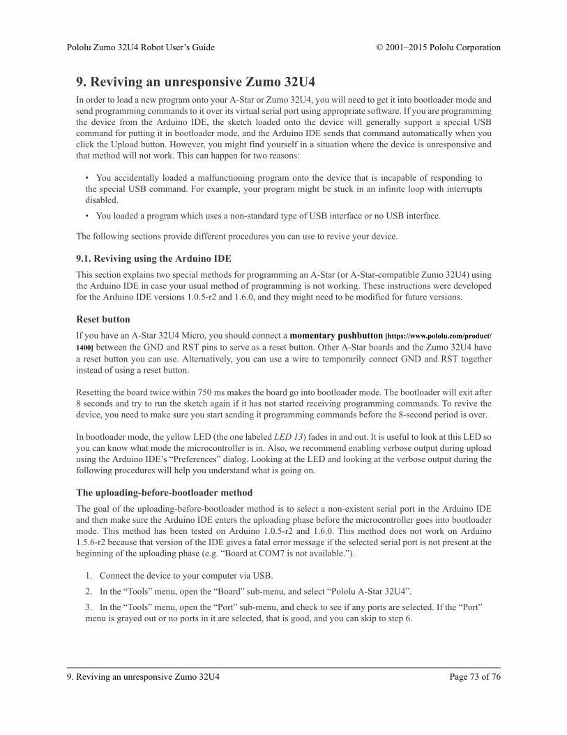
9. Reviving an unresponsive Zumo 32U4In order to load a new program onto your A-Star or Zumo 32U4, you will need to get it into bootloader mode andsend programming commands to it over its virtual serial port using appropriate software. If you are programmingthe device from the Arduino IDE, the sketch loaded onto the device will generally support a special USBcommand for putting it in bootloader mode, and the Arduino IDE sends that command automatically when youclick the Upload button. However, you might find yourself in a situation where the device is unresponsive andthat method will not work. This can happen for two reasons:
• You accidentally loaded a malfunctioning program onto the device that is incapable of responding tothe special USB command. For example, your program might be stuck in an infinite loop with interruptsdisabled.
• You loaded a program which uses a non-standard type of USB interface or no USB interface.
The following sections provide different procedures you can use to revive your device.
9.1. Reviving using the Arduino IDEThis section explains two special methods for programming an A-Star (or A-Star-compatible Zumo 32U4) usingthe Arduino IDE in case your usual method of programming is not working. These instructions were developedfor the Arduino IDE versions 1.0.5-r2 and 1.6.0, and they might need to be modified for future versions.
Reset buttonIf you have an A-Star 32U4 Micro, you should connect a momentary pushbutton [https://www.pololu.com/product/1400] between the GND and RST pins to serve as a reset button. Other A-Star boards and the Zumo 32U4 havea reset button you can use. Alternatively, you can use a wire to temporarily connect GND and RST togetherinstead of using a reset button.
Resetting the board twice within 750 ms makes the board go into bootloader mode. The bootloader will exit after8 seconds and try to run the sketch again if it has not started receiving programming commands. To revive thedevice, you need to make sure you start sending it programming commands before the 8-second period is over.
In bootloader mode, the yellow LED (the one labeled LED 13) fades in and out. It is useful to look at this LED soyou can know what mode the microcontroller is in. Also, we recommend enabling verbose output during uploadusing the Arduino IDE’s “Preferences” dialog. Looking at the LED and looking at the verbose output during thefollowing procedures will help you understand what is going on.
The uploading-before-bootloader methodThe goal of the uploading-before-bootloader method is to select a non-existent serial port in the Arduino IDEand then make sure the Arduino IDE enters the uploading phase before the microcontroller goes into bootloadermode. This method has been tested on Arduino 1.0.5-r2 and 1.6.0. This method does not work on Arduino1.5.6-r2 because that version of the IDE gives a fatal error message if the selected serial port is not present at thebeginning of the uploading phase (e.g. “Board at COM7 is not available.”).
1. Connect the device to your computer via USB.
2. In the “Tools” menu, open the “Board” sub-menu, and select “Pololu A-Star 32U4”.
3. In the “Tools” menu, open the “Port” sub-menu, and check to see if any ports are selected. If the “Port”menu is grayed out or no ports in it are selected, that is good, and you can skip to step 6.
Pololu Zumo 32U4 Robot User’s Guide © 2001–2015 Pololu Corporation
9. Reviving an unresponsive Zumo 32U4 Page 73 of 76

4. Reset the board twice to get the board into bootloader mode. While the board is in bootloader mode,quickly select the new serial port that corresponds to the bootloader in the “Port” menu.
5. After 8 seconds, the bootloader will exit and attempt to run the sketch again. Wait for the bootloader toexit. Verify that either the “Port” menu is grayed out or no ports in it are selected.
6. Click the Upload button. The Arduino IDE will compile your sketch and start uploading it.
7. As soon as the large status bar near the bottom of the IDE says “Uploading…”, press reset the boardtwice to get into bootloader mode.
The Arduino IDE will stay in the uploading phase for 10 seconds, waiting for a new serial port to appear. Oncethe serial port of the bootloader appears, the Arduino IDE will connect to it and send programming commands.
The bootloader-before-uploading methodThe goal of the bootloader-before-uploading method is to select the bootloader’s virtual serial port in the ArduinoIDE and then make sure the board is in bootloader mode at the time when the Arduino IDE enters the uploadingphase.
1. Connect the device to your computer via USB.
2. In the “Tools” menu, open the “Board” sub-menu and check to see if the “Pololu A-Star 32U4(bootloader port)” entry is visible. If this entry is visible, you can skip to step 6.
3. If you are using a 1.0.x version of the Arduino IDE, open the file [sketchbook location]/hardware/pololu/boards.txt using a text editor. If you are using a 1.5.x version of the Arduino IDE, open the file[sketchbook location]/hardware/pololu/avr/boards.txt using a text editor. You can see the sketchbooklocation in the Arduino IDE preferences dialog. The file you are looking for is part of the A-Star add-on.
4. In the boards.txt file that you opened, find the lines at the bottom of the file that start with #a-star32U4bp. Uncomment each of those lines by deleting the “#” character, and then save the file.
5. Close the Arduino IDE and restart it.
6. In the “Tools” menu, open the “Board” sub-menu and select “Pololu A-Star 32U4 (bootloader port)”.This entry is configured so that the Arduino IDE will send programming commands directly to selectedserial port, instead of trying to send a special USB command to the port to get it into bootloader mode andthen waiting for the new port to appear. By selecting this entry, the timing of the programming processbelow becomes easier, especially on Windows.
7. Prepare the computer to show you a list of its virtual serial ports. If you are using Windows, this meansyou should open the Device Manager. If you are on Linux or Mac OS X, this means you should open aTerminal and type the command ls /dev/tty* but do not press enter until the board is in bootloader modein the next step.
8. Reset the board twice to get the board into bootloader mode. While it is in bootloader mode, quicklylook at the list of serial ports provided by your operating system in order to determine what port thebootloader is assigned to.
9. Reset the board twice to get the board into bootloader mode again. While the board is in bootloadermode, quickly select the serial port of the bootloader in the Arduino IDE. The port can be selected in the“Port” sub-menu under “Tools”.
10. In the Arduino IDE, click the “Verify” button to compile your sketch. This could make the timingeasier during the next step.
11. Press the reset button twice to get the board into bootloader mode again. As soon as you see the yellowLED fading in and out, press the Upload button.
Pololu Zumo 32U4 Robot User’s Guide © 2001–2015 Pololu Corporation
9. Reviving an unresponsive Zumo 32U4 Page 74 of 76
The Arduino IDE will compile your sketch and then upload it to the selected serial port.
If the compilation of the sketch takes longer than 8 seconds, then this procedure will fail because the bootloaderwill time out and start trying to run the malfunctioning sketch again. If that happens, try the procedure againusing a simpler sketch such as the Blink example that can be found under File > Examples > 01.Basics > Blink.
After reviving your device, be sure to change the Board setting back to “Pololu A-Star 32U4” and select the rightPort.
9.2. Reviving using AVRDUDEThis section explains a special method for reviving an A-Star or Zumo 32U4 using the command-line utilityAVRDUDE [http://www.nongnu.org/avrdude/] in case your usual method of programming is not working.AVRDUDE stands for “AVR Downloader/UploaDEr”, and it is compatible with the A-Star bootloader.
If you have an A-Star 32U4 Micro, you should connect a momentary pushbutton [https://www.pololu.com/product/1400] between the GND and RST pins to serve as a reset button. Other A-Star boards and the Zumo 32U4 havea reset button you can use. Alternatively, you can use a wire to temporarily connect GND and RST togetherinstead of using a reset button.
1. Connect the device to your computer via USB.
2. Prepare the computer to show you a list of its virtual serial ports. If you are using Windows, this meansyou should open the Device Manager. If you are on Linux or Mac OS X, this means you should open aTerminal and type the command ls /dev/tty* but do not press enter until the board is in bootloader modein the next step.
3. Press the reset button twice within 750 ms to make the AVR go into bootloader mode. You should seethe yellow LED fading in and out when the AVR is in bootloader mode. While it is in bootloader mode,quickly look at the list of serial ports provided by your operating system in order to determine what port thebootloader is assigned to.
4. Type the following command in your terminal and replace COM4 with the name of the bootloader’sserial port, but do not press enter yet. This command will erase the malfunctioning program on the devicebut preserve the bootloader.
avrdude -c avr109 -p atmega32U4 -P COM4 -e
5. Press the reset button twice within 750 ms to make the AVR go into bootloader mode.
6. Quickly run the command you typed previously. The command needs to be run within 8 seconds ofstarting the bootloader, or else the bootloader will exit and try to run the malfunctioning program again.
By following the instructions above, the malfunctioning program on the device will be erased and the devicewill stay in bootloader mode indefinitely. You can now load another program onto it using the Arduino IDE orAVRDUDE.
Pololu Zumo 32U4 Robot User’s Guide © 2001–2015 Pololu Corporation
9. Reviving an unresponsive Zumo 32U4 Page 75 of 76

10. Related resourcesTo learn more about using the Zumo 32U4, see the following list of resources:
• The Arduino IDE has many examples [http://arduino.cc/en/Tutorial/HomePage] that can run on the Zumo32U4 (although note that the Zumo’s on-board hardware might conflict with some of these examples).
• The Arduino website has a Language Reference [http://arduino.cc/en/Reference/HomePage], a wiki called theThe Arduino Playground [http://playground.arduino.cc/], and other resources.
• The Zumo 32U4 uses the same microcontroller as the Arduino Leonardo [https://www.pololu.com/product/2192] and Arduino Micro [https://www.pololu.com/product/2188], so you can search the Internet for relevantprojects and code examples that use one of those boards.
• Atmel’s ATmega32U4 documentation [http://www.atmel.com/devices/atmega32u4.aspx] has theATmega32U4 datasheet and many related documents.
• AVR Libc Home Page [http://www.nongnu.org/avr-libc/]: this page documents the standard library offunctions that you can use with GNU C and C++ compilers for the AVR.
• Zumo 32U4 Arduino library [https://github.com/pololu/zumo-32u4-arduino-library]
• Zumo32U4 library documentation [https://pololu.github.io/zumo-32u4-arduino-library]
• LUFA – the Lightweight USB Framework for AVRs [http://www.fourwalledcubicle.com/LUFA.php]
• WinAVR [http://winavr.sourceforge.net/]
• Atmel Studio [http://www.atmel.com/microsite/atmel-studio/]
• AVRDUDE [http://www.nongnu.org/avrdude/]
• AVR Freaks [http://www.avrfreaks.net/]
Datasheets for some of the components found on the Zumo 32U4 are available below:
• ATmega32U4 documentation [http://www.atmel.com/devices/atmega32u4.aspx]
• Texas Instruments DRV8838 motor driver datasheet [https://www.pololu.com/file/download/drv8838.pdf?file_id=0J806] (1MB pdf)
• Sharp GP2S60 compact reflective photointerrupter datasheet [https://www.pololu.com/file/download/GP2S60_DS.pdf?file_id=0J683] (164k pdf)
• Vishay TSSP77038 IR receiver module datasheet [https://www.pololu.com/file/download/tssp77038.pdf?file_id=0J615] (268k pdf)
• ST LSM303D 3D accelerometer and 3D magnetometer module datasheet [https://www.pololu.com/file/download/LSM303D.pdf?file_id=0J703] (1MB pdf)
• ST L3GD20H three-axis digital-output gyroscope datasheet [https://www.pololu.com/file/download/L3GD20H.pdf?file_id=0J731] (3MB pdf)
• Texas Instruments TPS2113A power multiplexer datasheet [https://www.pololu.com/file/download/tps2113a.pdf?file_id=0J771] (1MB pdf)
Finally, we would like to hear your comments and questions on the Zumo section of the Pololu RoboticsForum [http://forum.pololu.com/viewforum.php?f=29]!
Pololu Zumo 32U4 Robot User’s Guide © 2001–2015 Pololu Corporation
10. Related resources Page 76 of 76