Politecnico di Milano di Milano Scuola di Ingegneria Industriale e dell’Informazione Master of...
135
Politecnico di Milano Scuola di Ingegneria Industriale e dell’Informazione Master of Science Engineering of Computer Systems Model Driven Development of iOS Apps with IFML By: F´ elix Javier Acero Salazar Student ID: 795545 Supervisor: Prof. Marco Brambilla December 2014
Transcript of Politecnico di Milano di Milano Scuola di Ingegneria Industriale e dell’Informazione Master of...
Politecnico di Milano
Scuola di Ingegneria Industriale e dell’Informazione
Master of ScienceEngineering of Computer Systems
Model Driven Development
of iOS Apps with IFML
By: Felix Javier Acero SalazarStudent ID: 795545
Supervisor: Prof. Marco Brambilla
December 2014


To my mum, my cousin and my girlfriend.For their unconditional support and honest advice

Abstract
Multi-platform mobile development has never been as relevant as it is today.Every year, markets are flood with new and more powerful mobile devices,that pack several sensors, allow for richer user interactions, and run oneof several operating systems. This scenario has put software developers ina troublesome situation, in which several versions of the same application— one for each major mobile platform – has to be developed, tested andsupported.
To partially address this problem, an entire ecosystem of multi-platform de-velopment tools has appeared, promising to help developers reduce the over-head caused by the implementation of a cross-platform application. Eventhough these solutions operate under different assumptions and use differentlevels of abstraction, they ultimately require developers to program using anintermediate programming language, which is later transformed into its na-tive equivalent, or run within a constraint environment, like a web browser.
Developers, however, have fewer options in the modeling world.
With the recent adoption by the Object Management Group (OMG) of anew standard [21] an opportunity for a Model Driven solution has arisen.The standard introduces the Interaction Flow Modeling Language or IFML,which can be used in tandem with UML, to describe the fundamental aspectsof modern mobile, web and desktop applications. In this way, a set of codegenerators — one for each major mobile platform – could be developed, totransform the IFML and UML models of an application, into their nativeequivalents. A solution like this will benefit from the advantages offered bya Model Driven approach, allowing developers to focus in the design of thedifferential aspects of their applications, instead of having to worry aboutthe implementation details.
To approach this Model Driven solution, our project focuses in the devel-opment of iOS applications with IFML, through the development of a codegeneration tool. Additionally, building on the experience and knowledgegathered in the generation process, we propose a set of extensions for theIFML metamodel, that aim to broaden the scope and modeling capabilitiesof the language.
Sommario
Lo sviluppo delle applicazioni mobili multi-piattaforma non aveva avuto larilevanza che ha nella attualita. Oggi anno il mercato offre nuovi e piu poten-ti dispositivi mobili con un numero importante di sensori che arricchisconol’interazione con l’usuario e che si eseguono in un ampio numero di sistemioperativi. Questo scenario a lasciato gli sviluppatori in una situazione unpoco problematica, richiedendo un esteso numero di versioni di una stessaapplicazione – una per oggi principale piattaforma mobile.
Per affrontare parzialmente questa problematica e aiutare gli sviluppatori, eapparso un intero ecosistema di strumenti, che promettono ridurre il lavoroaddizionale nella implementazione di una applicazione per diverse piattafor-me. Queste soluzioni vengono svolte sotto diverse assunzioni e usano diversilivelli di astrazione. Nonostante, lo sviluppo richiede in definitiva l’utilizzodi un linguaggio intermedio che successivamente sara trasformato nel lin-guaggio nativo equivalente o eseguito in un ambiente vincolato come un webbrowser.
Gli sviluppatori, tuttavia, hanno altre opzioni dentro il mondo della model-lazione.
Con la recente adozione di un nuovo standard [21], da parte del ObjectManagement Group (OMG), e sorta una opportunita per le soluzioni ModelDriven. Questo standard introduce il Interaction Flow Modeling Languageo IFML che puo essere utilizzato di pari passo con UML per descrivere gliaspetti fondamentali delle applicazioni mobili. In questo modo una serie digeneratori di codice – uno per oggi grande piattaforma mobile – potrebbeessere sviluppato per trasformare i modelli IFML e UML di una applicazione,nei loro codice nativo equivalente. Una soluzione come questa si beneficia deivantaggi offerti da un approccio Model Driven, permettendo agli sviluppatoridi concentrarsi nella progettazione degli aspetti delle loro applicazioni, invecedi doversi preoccupare dei dettagli d’implementazione.
Per affrontare la soluzione Model Driven, il nostro progetto si concentra nellarealizzazione d’applicazioni per iOS con IFML, attraverso lo sviluppo di unostrumento per la generazione di codice. Inoltre, basandoci sull’esperienza ele conoscenze riuniti nel processo di generazione, proponiamo una serie diestensioni per il metamodello di IFML, che mirano ad ampliare gli scopi ela capacita di modellazione del linguaggio.

Contents
1 Introduction 1
1.1 Context . . . . . . . . . . . . . . . . . . . . . . . . . . . . . . 1
1.2 Motivation . . . . . . . . . . . . . . . . . . . . . . . . . . . . 2
1.3 Objectives . . . . . . . . . . . . . . . . . . . . . . . . . . . . . 3
1.4 Structure . . . . . . . . . . . . . . . . . . . . . . . . . . . . . 3
2 Background 5
2.1 IFML . . . . . . . . . . . . . . . . . . . . . . . . . . . . . . . 5
2.2 iOS . . . . . . . . . . . . . . . . . . . . . . . . . . . . . . . . . 17
3 Approach 26
3.1 Overview . . . . . . . . . . . . . . . . . . . . . . . . . . . . . 26
3.2 Extensions . . . . . . . . . . . . . . . . . . . . . . . . . . . . . 27
3.3 Code Generation . . . . . . . . . . . . . . . . . . . . . . . . . 28
3.4 Tools . . . . . . . . . . . . . . . . . . . . . . . . . . . . . . . . 32
4 Extensions 33
4.1 General Extensions . . . . . . . . . . . . . . . . . . . . . . . . 34
4.2 Mobile Extensions . . . . . . . . . . . . . . . . . . . . . . . . 39
4.3 Private Extensions . . . . . . . . . . . . . . . . . . . . . . . . 44
5 Code Generation 49
5.1 Prototype App . . . . . . . . . . . . . . . . . . . . . . . . . . 50
vii
5.2 Target Architecture . . . . . . . . . . . . . . . . . . . . . . . 52
5.3 Mapping . . . . . . . . . . . . . . . . . . . . . . . . . . . . . . 59
5.4 Static Library . . . . . . . . . . . . . . . . . . . . . . . . . . . 65
5.5 Code Generators . . . . . . . . . . . . . . . . . . . . . . . . . 69
5.6 Integration . . . . . . . . . . . . . . . . . . . . . . . . . . . . 75
5.7 Packaging . . . . . . . . . . . . . . . . . . . . . . . . . . . . . 77
6 Conclusion 79
6.1 Results . . . . . . . . . . . . . . . . . . . . . . . . . . . . . . . 79
6.2 Critical Analysis . . . . . . . . . . . . . . . . . . . . . . . . . 80
6.3 Future Work . . . . . . . . . . . . . . . . . . . . . . . . . . . 80
Appendix A General Extensions Package 82
Appendix B Mobile Extensions Package 89
Appendix C Private Extensions Package 100
Note about References 120
Bibliography 121
Acknowledgments 124
viii
List of Figures
2.1 IFML Review - View Containers . . . . . . . . . . . . . . . . 72.2 IFML Review - Search . . . . . . . . . . . . . . . . . . . . . . 82.3 IFML Review - Bookmarked and Recent Words . . . . . . . . 92.4 IFML Review - Details . . . . . . . . . . . . . . . . . . . . . . 112.5 IFML Review - Navigation Flow . . . . . . . . . . . . . . . . 122.6 IFML Review - Events . . . . . . . . . . . . . . . . . . . . . . 142.7 IFML Review - Actions . . . . . . . . . . . . . . . . . . . . . 152.8 IFML Review - Activation Expressions . . . . . . . . . . . . . 16
3.1 Approach - Overview . . . . . . . . . . . . . . . . . . . . . . . 263.2 Approach - Code Generation . . . . . . . . . . . . . . . . . . 28
4.1 Extensions - Packages . . . . . . . . . . . . . . . . . . . . . . 344.2 General Extensions - Overview . . . . . . . . . . . . . . . . . 344.3 General Extensions - View Lifecycle Event . . . . . . . . . . . 354.4 General Extensions - Application Lifecycle Event . . . . . . . 364.5 Mobile Extensions - Overview . . . . . . . . . . . . . . . . . . 404.6 Mobile Extensions - Touch Event Hierarchy . . . . . . . . . . 414.7 Mobile Extensions - Mobile Sensor Hierarchy . . . . . . . . . 414.8 Mobile Extensions - Mobile Resource Event . . . . . . . . . . 424.9 Private Extensions - Overview . . . . . . . . . . . . . . . . . . 444.10 Private Extensions - Mobile Device . . . . . . . . . . . . . . . 454.11 Private Extensions - Mobile Context Variable . . . . . . . . . 464.12 Private Extensions - Acceleration, Rotation and Attitude . . 464.13 Private Extensions - Orientation and Battery Status . . . . . 474.14 Private Extensions - Proximity and Network . . . . . . . . . . 474.15 Private Extensions - Direction and Location . . . . . . . . . . 48
5.1 Transformation Overview . . . . . . . . . . . . . . . . . . . . 495.2 Movie Manager - Main windows . . . . . . . . . . . . . . . . . 505.3 Movie Manager - Movie Details . . . . . . . . . . . . . . . . . 515.4 Movie Manager - Add Movie Form . . . . . . . . . . . . . . . 525.5 Movie Manager - Generated App . . . . . . . . . . . . . . . . 535.6 Target Architecture - Oveview . . . . . . . . . . . . . . . . . 545.7 Target Architecture - Movie Manager . . . . . . . . . . . . . 55
ix
5.8 Target Architecture - Core Entities . . . . . . . . . . . . . . . 565.9 Target Architecture - Presenter’s Hierarchy . . . . . . . . . . 575.10 Target Architecture - Method’s Hierarchy . . . . . . . . . . . 575.11 Target Architecture - Core entities and methods . . . . . . . 585.12 Target Architecture - Flow Controller . . . . . . . . . . . . . 585.13 Target Architecture - Actions Facade . . . . . . . . . . . . . . 595.14 Mapping - IFML Model . . . . . . . . . . . . . . . . . . . . . 605.15 Mapping - Actions . . . . . . . . . . . . . . . . . . . . . . . . 605.16 Mapping - Window . . . . . . . . . . . . . . . . . . . . . . . . 615.17 Mapping - Details . . . . . . . . . . . . . . . . . . . . . . . . 635.18 Mapping - Details . . . . . . . . . . . . . . . . . . . . . . . . 635.19 Mapping - Interaction Flow . . . . . . . . . . . . . . . . . . . 645.20 Static Library - Package Structure . . . . . . . . . . . . . . . 665.21 Static Library - SMM Classes . . . . . . . . . . . . . . . . . . 665.22 Static Library - PresenterViewController . . . . . . . . . . . . 675.23 Static Library - Generated Code . . . . . . . . . . . . . . . . 685.24 Static Library - Application Package . . . . . . . . . . . . . . 695.25 Code Generation - Folder Structure . . . . . . . . . . . . . . . 705.26 Code Generation - Main file . . . . . . . . . . . . . . . . . . . 715.27 Code Generation - Template Structure . . . . . . . . . . . . . 725.28 Code Generation - Actions Templates . . . . . . . . . . . . . 735.29 Code Generation - Flow Controller Template . . . . . . . . . 735.30 Code Generation - Generated Code . . . . . . . . . . . . . . . 745.31 Code Generation - Inherintance from the Static Library . . . 745.32 Code Generation - Movie Details Presenter Header . . . . . . 755.33 Code Generation - Movie Details Presenter Implementation . 755.34 Integration - Automation Scripts . . . . . . . . . . . . . . . . 765.35 Packaging - Generation Wizard . . . . . . . . . . . . . . . . . 77
x
Chapter 1
Introduction
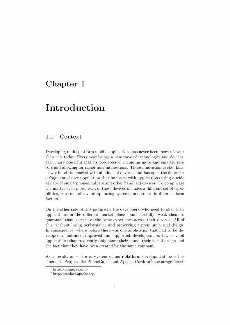
1.1 Context
Developing multi-platform mobile applications has never been more relevantthan it is today. Every year brings a new wave of technologies and devices,each more powerful that its predecessor, including more and smarter sen-sors and allowing for richer user interactions. These innovation cycles, haveslowly flood the market with all kinds of devices, and has open the doors fora fragmented user population that interacts with applications using a widevariety of smart phones, tablets and other handheld devices. To complicatethe matter even more, each of these devices includes a different set of capa-bilities, runs one of several operating systems, and comes in different formfactors.
On the other side of this picture lie the developers, who need to offer theirapplications in the different market places, and carefully tweak them toguarantee that users have the same experience across their devices. All ofthis, without losing performance and preserving a premium visual design.In consequence, where before there was one application that had to be de-veloped, maintained, improved and supported, developers now have severalapplications that frequently only share their name, their visual design andthe fact that they have been created by the same company.
As a result, an entire ecosystem of muti-platform development tools hasemerged. Project like PhoneGap 1 and Apache Cordova2 encourage devel-
1 http://phonegap.com/2 http://cordova.apache.org/
1
opers to program cross-platform applications through the usage of alreadyfamiliar web technologies like HTML, Javascript and CSS. Other solutionslike Titanium3 and Xamarin 4, advocate the usage of a cross-platform tool,that allows the creation of native applications.
Developers however, have fewer alternatives to address the same issue at amodeling level.
1.2 Motivation
For years, software developers have used modeling tools to design their ap-plications at a platform independent level. The Unified Modeling Languageor UML [24], is one of these tools. However, as powerful and expressive asUML may be, there are still several aspects involved in the development ofmodern mobile, web and desktop applications that are not covered by it.
An important omission in UML, corresponds to the specification of the front-end of an application.
To bridge this gap, the Object Management Group has adopted a new stan-dard, the Interaction Flow Modeling Language or IFML [21]. This modelinglanguage can be used to describe the principal dimensions of an application’sfront-end. Moreover, since the entities and classes in the modeling languageare based on a formal metamodel, code generators and modeling extensionscan be proposed.
As a consequence, a Model Driven Development (MDD) approach for devel-oping cross-platform mobile applications based on IFML could be proposed.In this approach, IFML could be used to describe and specify the front endof an application. In turn, UML could be used to describe the nuances ofthe business logic. And finally, a set of code generators could be used totranslate the elements in the IFML and the UML models, into the equivalentnative code of the major mobile platforms — Android, iOS and WindowsPhone.
In contrast with other cross platform development solutions, like PhoneGap,Apache Cordova, Titanium and Xamarin, this MDD approach presents twoadvantages. First it would operate at a higher level of abstraction, allowingdevelopers to focus in the differential aspects of their applications instead of
3 http://www.appcelerator.com/titanium/4 http://xamarin.com/
2
worry about the implementation details. Second, it would produce, throughthe code generators, native code that could be later enhanced and optimizedto obtain the best performance.
1.3 Objectives
The Model Driven Development approach of our project was based on theInteraction Flow Modeling Language (IFML) [21], and focused on iOS asthe main target platform.
On one hand, we chose IFML, because with it, software developers canmodel the front end of their applications, at a platform independent level.Furthermore, since it integrates very well with other modeling languages,choosing IFML also meant that designers could use a language like UML todescribe the nuances of the business logic of their applications.
On the other hand, we chose to focus on iOS since it remains as one of themore popular mobile operating systems in the market. In fact, according toa recent study conducted by the International Data Corporation [23], iOSis the second most popular mobile operating system with a share of 11.7%of all mobile devices shipped in 2014 — surpassed only by Android, whichremains as the most popular operating system with a market share of 84.7%.
Particularly, in our project we focused in two objectives. First, to enhancethe portability of the modeling language by developing a code generator foriOS. And second, to broaden the modeling capabilities of IFML by addinga set of mobile specific extensions to its metamodel.
1.4 Structure
This document is organized in six different chapters.
In Chapter 1 we introduce some of the challenges posed by multi-platformmobile development, and the different solutions that have been proposed inthe industry to face them. Then, we motivate the opportunity for a modeldriven approach based on IFML and UML. Finally, we highlight the mainobjectives of the project.
In Chapter 2 we cover all the background information needed to grasp the
3
basic concepts of IFML and iOS. In the case of IFML, we introduce thecore entities of the modeling language and provide several examples basedon a simple dictionary app. For iOS instead, we briefly cover the maincharacteristics of the platform, the architecture of a typical iOS applicationand other traits that distinguish iOS from other mobile operating systems.
In Chapter 3, we provide an overview of the process followed during theproject. We start by discussing the strategy we used to identify potentialextensions for IFML. Then, we introduce the the seven milestones that leadto the creation of the code generators , namely: design and implementationof the prototype app, definition of the target metamodel, creation of themapping rules, implementation of the static library, development of thecode generators, creation of the integration tools and packaging. Besidesthe methodology we present, at the end of the chapter, the tools used todevelop the deliverables of the project.
In chapter 4, we discuss at length some of the extensions that we proposed tobroaden the modeling capabilities of IFML. However, a complete descriptionof each of these extensions can be found in the appendices of this document.
In Chapter 5, we give a deeper look to the intermediate results that weachieved while working on the code generators. In this way, the ”Proto-type App” section starts describing the application that we used to guidethe generation process. The ”Target Architecture” section, introduces thearchitecture of the generated apps from a software driven perspective and amodel driven point of view. In the ”Mapping” section, we use some examplesto illustrate the rules that map an IFML model into our target metamodel.Then we present the contents of the ”Static Library”, and discuss how theycontribute to the shape of our solution. The ”Code Generation” section in-stead, reviews the generation templates and provides a glimpse of the finalproject structure and the shape of generated Objective-C code. In the ”Inte-gration” section, we discuss the motivations that lead to the development ofsuch tools and provide an overview of their functionality. The ”Packaging”section describes the strategy we used to make the project outputs moreaccessible to potential users.
In Chapter 6, we present the results of the project, highlighting the differenttools that were developed as well the proposed extensions. Then we discussthe project shortcomings, and the opportunities that should be explored infuture research efforts.
4
Chapter 2
Background
2.1 IFML
2.1.1 Basic Concepts
IFML is a modeling language designed to tackle the main challenges of thefront end specification of an app, through a small set of extensible entitiesbased on a formal meta-model that provides them with rich semantics.
At its core, IFML is meant to be simple and flexible, but perhaps moreimportantly IFML is meant to be abstract. This allows the possibility ofdefining the main traits of an application’s front end making as few visualcommitments as possible. In contrast to other approaches like, wireframes orlo-fi mockups, IFML has the advantage of focusing on the principal aspectsof the front end without dealing with their concrete visual implementation,which may vary radically from platform to platform. Similarly, IFML ben-efits from its formality by allowing the implementation of code generators– which could reduce the development time by automatically producing agreat percentage of the code needed to implement an application.
Put in different words, IFML can be described as a language that formalizesthe front end of modern web, mobile and desktop applications, providingan appropriate separation between the front end requirements and theirconcrete visual implementation.
Another important trait of IFML is its extensibility, which allows the lan-guage to remain small and general while permitting modelers and designers
5
to specialize certain components in order to enrich the semantics of theirmodels and make the diagrams more readable.
As for the main motivations of IFML, the scenario is clear. The past decadehas seen a huge change in the application development scene. While someyears ago, applications were mostly being developed for a specific platformand run on devices that allowed for a small set of interactions, currentapplications need to target several platforms and offer support for a widerange of devices that allow users interact in many different ways. Moreover,the new focus on general consumer markets, brought by the appearanceof centralized marketplaces, has made usability and user interface designprimary concerns and a central part of the development life-cycle of anapplication.
More formally, IFML is a modeling language akin to UML, which has ac-companied for years the community of software development. Like UML,IFML aims to define and model certain aspects of an application at an ab-stract level based on a formal meta-model that provides each of the entitiesof the language with clear semantics. In contrast, while UML offers a familyof diagrams, each of which is meant to capture a particular aspect of anapplication, IFML focuses on the front end and does so by using a singletype of diagram.
As stated previously, IFML’s main objective is to formalize and specifythe different dimensions that make up the front end of an application. Inconsequence, a good way to get acquainted with the main entities of thelanguage is by dividing them according to the particular aspect of the frontend that they intent to model, namely: View Composition, Navigation,Content, Interaction and Context.
With the aim of showing how each of the main entities of IFML may be usedin practice, throughout this section we will model a dictionary application.The main requirements of the application are:
• The application must allow the user to enter a word to see its definition.
• The application must allow the user to see a list with the words thehe has previously searched for.
• The application must allow a user to bookmark a word for later refer-ence.
• The application must allow a user to see a list with the words he hasbookmarked.
6
2.1.2 View Composition
A good place to start modeling this app is the view hierarchy. This hier-archy, identifies the main sections and top level containers, providing somehint regarding their visibility and rechability. According to the outlinedrequirements, the dictionary app has three main sections: Search, Recentand Bookmarks, as well as an independent section dedicated to show thedefinition of a word. To model this basic structure in IFML, we will needto use View Containers.
View Containers
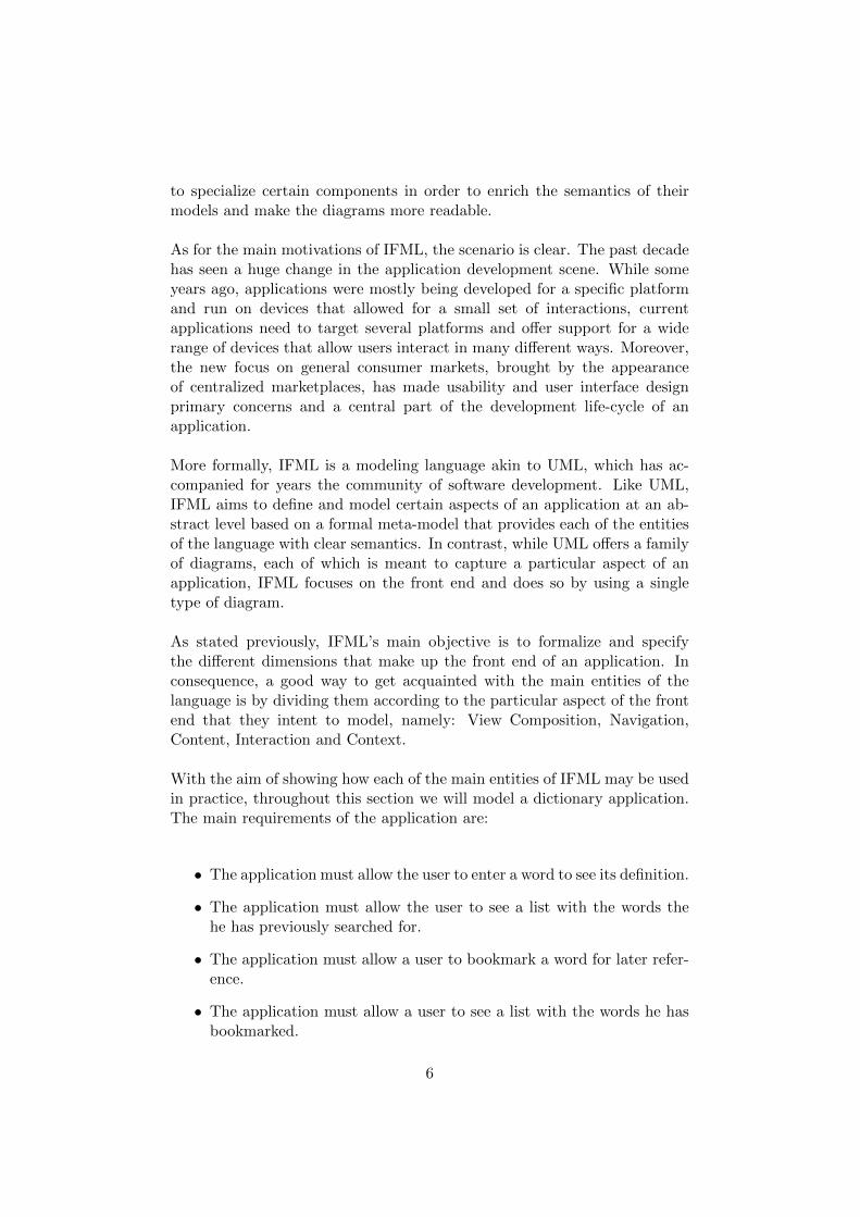
View Containers are the most fundamental visual units of IFML. They arethe foundation of the application’s view hierarchy and can accommodateboth View Containers and View Components [21]. As shown in Figure2.1, we can use 6 View Containers to model the View Composition of theapplication. The first container (Dictionary App) acts as the root of theview hierarchy and will accommodate and manage all the other containersof the app. Under it, we find two View Containers, Main and Word.
Figure 2.1: IFML Review - View Containers
While the Word View Container is rather simple, the Main View Containermanages a set of mutually exclusive containers, namely Search, Recent andBookmarks. To model this behavior, each of them has several tagged valuesthat indicate their visibility and rechability. In this way, the Main View
7
Container is tagged as [XOR], to express the mutually exclusive behaviorof its direct children, while the Search, Recent and Bookmarks containersare tagged with an [L] – landmark, to imply sibling navigation. Finallythe Search View Container is tagged with a [D] – default, indicating that itshould be the default section shown to the user.
2.1.3 Content
The next step will be to determine the information that needs to be shownin each of the previously identified containers, as well as the data that needsto be captured from the user.
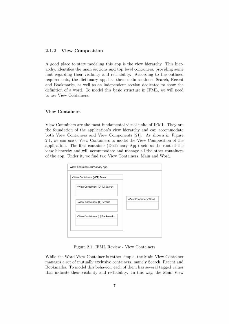
Let’s start with Search. This section, should prompt a search bar in which auser may enter a word in order to get its definition. To model this behaviorwe will need to make use of two of IFML’s platform independent extensions:Form and Simple Field.
Figure 2.2: IFML Review - Search
Forms
Forms in IFML are an extension of a much more generic entity called ViewComponent. As expected, they are used to model the capture of informationfrom the user through a set of fields [21]. In the Search section, we will needa form entity with one single field in which the user may introduce the wordshe wants the meaning of.
8
Fields
As stated previously, Fields are each of the elements that make up a Form.They could be of two types Simple Field or Selection Field, depending onwhether the user needs to introduce the data herself or if instead she canchoose from a list of options [21]. The search bar of our application needsto be modeled with a Simple Field, since the user must introduce the wordherself.
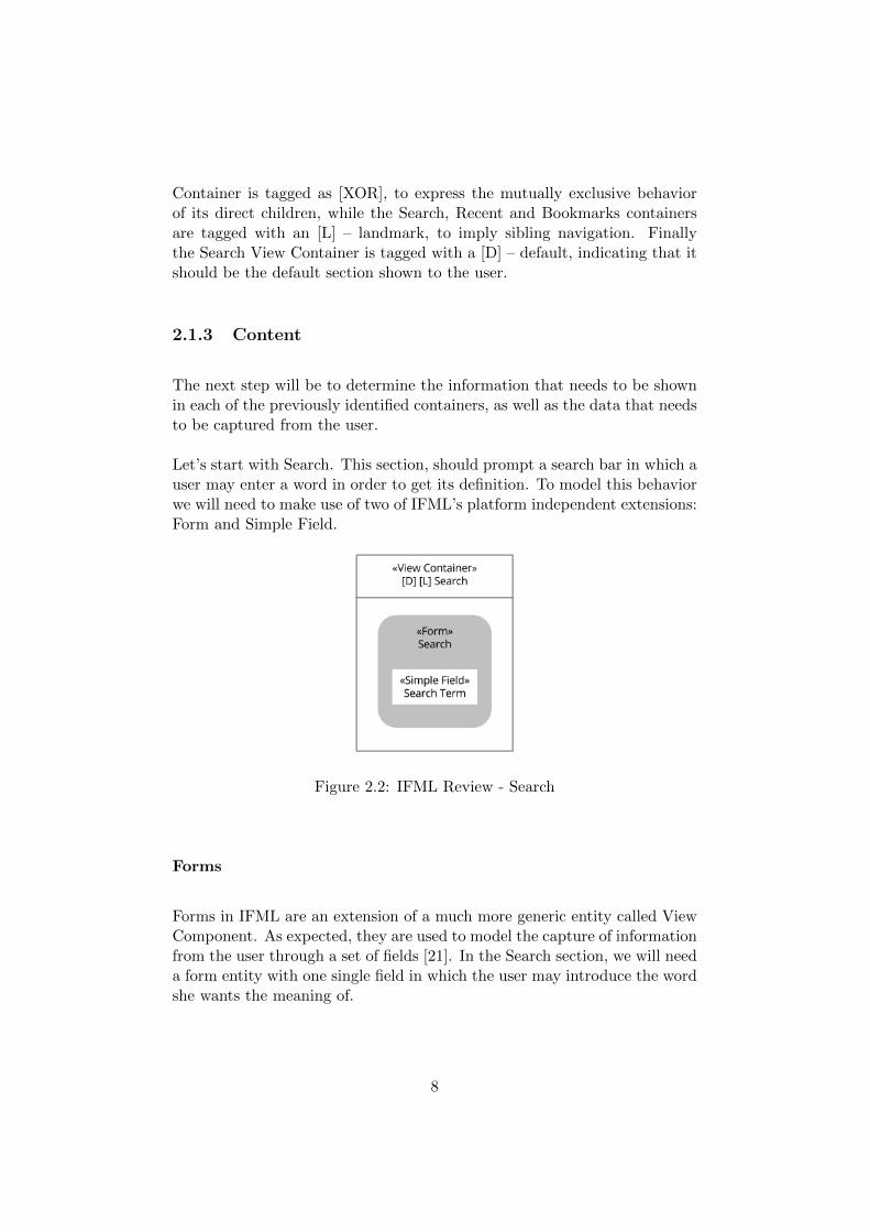
Now, lets analyze the Recent and Bookmarks sections (Figure 2.3). Bothof them need to show a list of words accompanied of a snippet of theirdefinition and an indication of whether they have been bookmarked. Tomodel this content, we will make use of two core entities of IFML, namely:Data Binding and Visualization Attribute; and one entity that belongs tothe platform independent extension of the language: List.
Figure 2.3: IFML Review - Bookmarked and Recent Words
Data Bindings
DataBindings are used to express the relations between the view and modellayers of a MVC architecture. That is, a Data Binding should be usedto imply that a particular View Component publishes the data of a givenDomain Object [21]. In our case, the Recent Section shows words that belongto the Recent Words collection, while the Bookmarks Section shows wordsthat belong to the Bookmarked Words collection. The previous distinctionregarding the domain objects, is obviously more clear under the light of theapplication’s domain model, which is not included in the current documentfor simplicity. However, in most of the examples available in the literature
9
a detailed Domain Model is provided and later referenced within the IFMLmodels.
Visualization Attributes
Visualization Attributes like Data Bindings, are a specialization of a fun-damental entity of IFML called View Component Part, and are meant tofurther specify the behavior of the View Components [21]. While a DataBinding may specify which particular Domain Object needs to be presentedby a View Component, the Visualization Attributes instead, allow the soft-ware designer to specify explicitly which attributes and values need to be dis-closed. In case of the dictionary app, both Recent and Bookmarked Wordsneed to show the word along with a snippet of its definition. Similarly, anindication of whether the word has been bookmarked is needed.
List
The last entity depicted in Figure 2.3 is List. Lists are entities that extendthe behavior of a View Component, and model a component able to displaya collection of objects retrieved through a Data Binding [21]. Both, Recentand Bookmark View Containers include a List View Component to showthe recently searched words and the bookmarked words respectively.
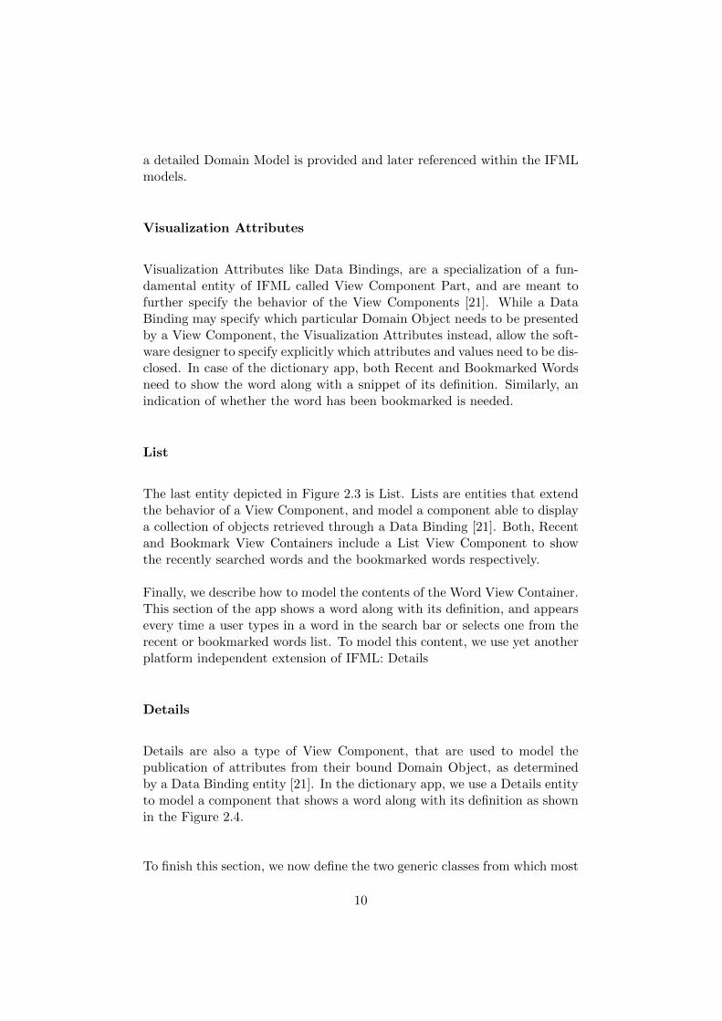
Finally, we describe how to model the contents of the Word View Container.This section of the app shows a word along with its definition, and appearsevery time a user types in a word in the search bar or selects one from therecent or bookmarked words list. To model this content, we use yet anotherplatform independent extension of IFML: Details
Details
Details are also a type of View Component, that are used to model thepublication of attributes from their bound Domain Object, as determinedby a Data Binding entity [21]. In the dictionary app, we use a Details entityto model a component that shows a word along with its definition as shownin the Figure 2.4.
To finish this section, we now define the two generic classes from which most
10
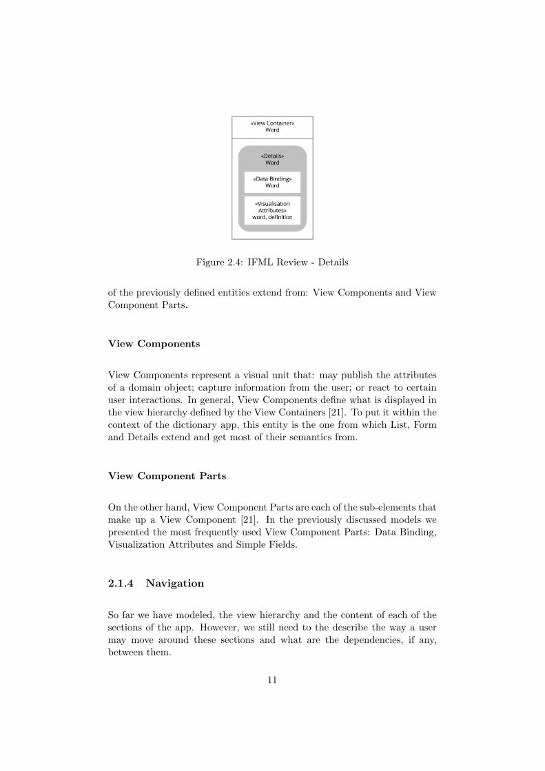
Figure 2.4: IFML Review - Details
of the previously defined entities extend from: View Components and ViewComponent Parts.
View Components
View Components represent a visual unit that: may publish the attributesof a domain object; capture information from the user; or react to certainuser interactions. In general, View Components define what is displayed inthe view hierarchy defined by the View Containers [21]. To put it within thecontext of the dictionary app, this entity is the one from which List, Formand Details extend and get most of their semantics from.
View Component Parts
On the other hand, View Component Parts are each of the sub-elements thatmake up a View Component [21]. In the previously discussed models wepresented the most frequently used View Component Parts: Data Binding,Visualization Attributes and Simple Fields.
2.1.4 Navigation
So far we have modeled, the view hierarchy and the content of each of thesections of the app. However, we still need to the describe the way a usermay move around these sections and what are the dependencies, if any,between them.
11
To model these relationships IFML provides entities like Navigation Flowsand Parameter Bindings that allow a software designer to model navigationand parametrized communications between the View Elements of an app.
Figure 2.5: IFML Review - Navigation Flow
Navigation Flows
Navigation Flows are a special type of a more generic class called InteractionFlow, that model communications between a source and a target InteractionFlow Elements. Despite their broad nature, Navigation Flows are frequentlyused to model a visual transition from a source View Element to a targetView Element, making them the most suitable construct for expressing nav-igation in IFML [21].
While the previously discussed Main View Container already describes thenavigation dynamics that should govern the Search, Recent and BookmarksView Containers, there is still one section that cannot be reached: Words.
According to our list of requirements, this section needs to be shown everytime a user enters a word in the search bar, or every time a user selects aword from either the Recent Words or the Bookmarked Words list.
To make the Word Section reachable, we shall create three Navigation Flowsstarting from the Search, Recent and Bookmarks sections respectively, andtargeting the Word View Container. For now, let’s assume that a user hasa way of triggering these transitions, and we will later dive deeper on the
12
specific entities that can be used to describe such behavior.
Finally, we need to formalize the previously defined navigation flows bymeans of parameters that will tell the Word View Container which wordwas typed in or selected, to show the appropriate definition. To achievethis, we need to make use of Parameter Bindings, as shown in Figure 2.5
Parameter Bindings
Parameter Bindings express the input / output dependencies that exist be-tween the source and target of an Interaction Flow. That is, they stipulatehow the outputs of the source entity, map into the inputs of the target one[21]. As shown in the Figure 2.5, we will need to stipulate a parameterbinding for each of the navigation flows, providing the appropriate mappingin every case.
Before finalizing this section, we introduce the concept of Interaction Flows,since they are a generalization of the aforementioned Navigation Flows andconstitute a fundamental part of IFML.
Interaction Flows
Interaction Flows represent the communication between a couple of ViewElements or between a View Element and an Action [21]. Such communi-cations are usually triggered by the occurrence of an event, and may implya change of state in the user interface. In any case, an Interaction Flow istypically associated with a Parameter Binding to specify the dependenciesbetween the the source and target entities. Finally, an Interaction Flowcan be either a Navigation Flow, implying parameter passing and change offocus, or a Data Flow, implying parameter passing only.
2.1.5 Interaction
It is now time to present the possibilities that IFML offers to model thedifferent interactions that a user may have with the front end of an applica-tion.
In the case of the dictionary a user may interact with the application inthree different ways: introduce a string to perform a search; select a word
13
out of the Recent or Bookmarked word lists; and bookmark a particularword. Even though all of these interactions imply actions performed by theuser, they also involve different reactions that are usually described by theapplication logic.
Using IFML a software designer is able to: model the specific interactionsthat must performed by a user; identify the Entity that is in charge ofmonitor the occurrence of such interactions; and determine the task thatthe application should perform in response to them. Specifically, IFMLdefines two entities that model the user’s and the application’s side of aninteraction: Events and Actions.
Events
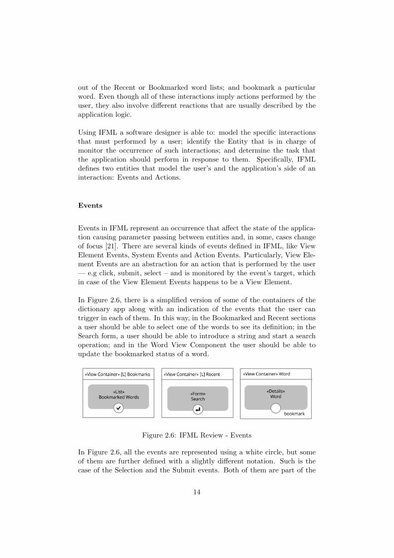
Events in IFML represent an occurrence that affect the state of the applica-tion causing parameter passing between entities and, in some, cases changeof focus [21]. There are several kinds of events defined in IFML, like ViewElement Events, System Events and Action Events. Particularly, View Ele-ment Events are an abstraction for an action that is performed by the user— e.g click, submit, select – and is monitored by the event’s target, whichin case of the View Element Events happens to be a View Element.
In Figure 2.6, there is a simplified version of some of the containers of thedictionary app along with an indication of the events that the user cantrigger in each of them. In this way, in the Bookmarked and Recent sectionsa user should be able to select one of the words to see its definition; in theSearch form, a user should be able to introduce a string and start a searchoperation; and in the Word View Component the user should be able toupdate the bookmarked status of a word.
Figure 2.6: IFML Review - Events
In Figure 2.6, all the events are represented using a white circle, but someof them are further defined with a slightly different notation. Such is thecase of the Selection and the Submit events. Both of them are part of the
14
platform independent extensions of IFML, and aim to refine the semanticsof the language by providing a better description of the kind of interactionthat is expected from the user. In this way, the Select Event, associatedwith the Bookmarked Words, implies that the user needs to select one ofthe items of the list; and the Submit Event, indicates that the user mustintroduce and submit some data.
As stated previously, there are always two sides in an interaction: one ofthem is the action performed by the user — which in IFML is modeledthrough Events —, and the other is the task that is performed by the systemin response to it. To model the latter, IFML uses Actions.
Actions
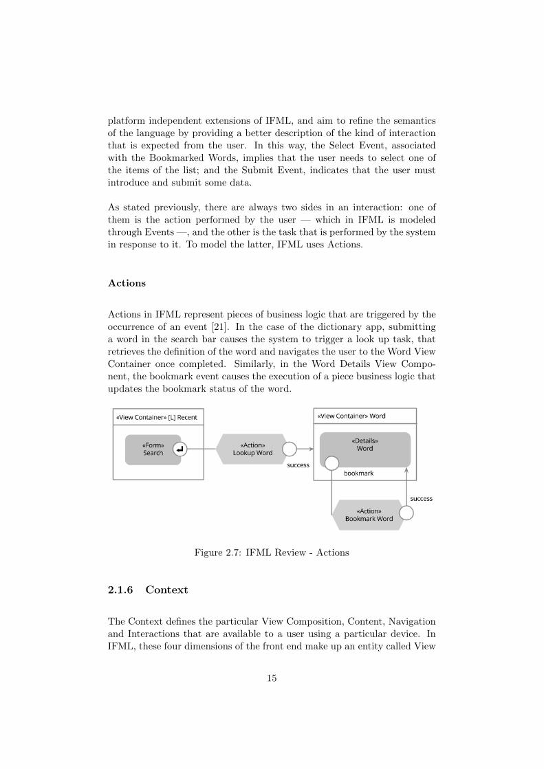
Actions in IFML represent pieces of business logic that are triggered by theoccurrence of an event [21]. In the case of the dictionary app, submittinga word in the search bar causes the system to trigger a look up task, thatretrieves the definition of the word and navigates the user to the Word ViewContainer once completed. Similarly, in the Word Details View Compo-nent, the bookmark event causes the execution of a piece business logic thatupdates the bookmark status of the word.
Figure 2.7: IFML Review - Actions
2.1.6 Context
The Context defines the particular View Composition, Content, Navigationand Interactions that are available to a user using a particular device. InIFML, these four dimensions of the front end make up an entity called View
15
Point.
Following the previous definition, IFML allows a software designer to defineseveral Viewpoints for his application, identifying for each of them the par-ticular context conditions needed to activate it. Such Context is modeled interms of Context Dimensions that evaluate variables related with the User,the Position and the Device.
To show how the Context information may alter the actions available toa user in an application, let’s suppose that in the dictionary app only thepremium users are able to bookmark words. This additional requirement,will imply a runtime check in order to figure out whether the active user isallowed to update the bookmark status of a word. To model this feature,and express other traits of the Context, IFML has entities like the previouslydefined Context and Context Dimension. On the other hand the run-timeevaluations are modeled through Activation Expressions.
Activation Expressions
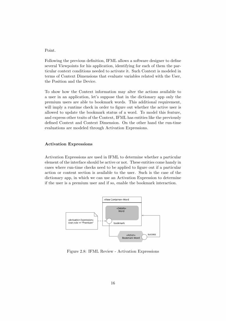
Activation Expressions are used in IFML to determine whether a particularelement of the interface should be active or not. These entities come handy incases where run-time checks need to be applied to figure out if a particularaction or content section is available to the user. Such is the case of thedictionary app, in which we can use an Activation Expression to determineif the user is a premium user and if so, enable the bookmark interaction.
Figure 2.8: IFML Review - Activation Expressions
16
2.2 iOS
2.2.1 Technologies
One of the reasons why programming for iOS is regarded as a daunting task,is because there are several concepts and abstractions that a programmerneeds to understand, before starting to program applications. A good start-ing point for this journey, is the study of the very technologies that powerthe platform, as well as the services that they provide to the developers.
The architecture of the platform can be seen as a four layered system, or-ganized in ascending level of abstraction. At the lowermost level we findCore-OS [8] that provides several APIs to: communicate with external de-vices, manage bluetooth communications, manage security, provide managedfile-system access, support concurrency and threads, memory allocation andmanagement, among others.
Following the stack, we encounter the Core Services [8] layer that encom-passes APIs for networking operations, model management and arguably themost important framework of the platform: Foundation. This framework,contains Objective-C wrappers for basic classes like: NSObject, NSDate,NSData, NSString, NSInteger, NSNumber as well as collections like NSAr-ray, NSDictionary and NSSet.
At the third level we find the Media Layer [8], that basically contains frame-works for image, video and audio management. Finally at the top of thestack, we find Cocoa Touch [8]. This framework promotes the Model-View-Controller (MVC) architecture, and provides the foundation for most iOSapps. In consequence, Cocoa Touch contains the family of classes that everyiOS programmer needs to be familiar with.
2.2.2 Objective-C
Another defining characteristic of the platform is the programming languagethat powers it: Objective-C. The language is currently supported and con-tinuously enhanced by Apple and is used for natively developing apps for theOSX and iOS operating systems. At a general level, Objective-C is an objectoriented superset of C [9] and inherits many of its traits, like the support oftwo files types (� .m � or implementation files and � .h � or header files),or the required tasks expected from the programmer to manage memoryallocation and deallocation of objects and data structures –although recent
17
enhancements on the compiler, have moved some of this burden away fromthe developer shoulders.
A defining trait of Objective-C is certainly its syntax, which mixes the useof the dot notation for property access (akin to Java attributes) and squarebrackets for message passing (similar to method invocation in Java). More-over, public, and private modifiers are managed through the distribution ofmethods and properties between the ”.m” and ”.h” files (in the case of thepublic and private modifiers) while instance and class methods are indicatedthrough the use of ” - ” and ” + ” respectively.
Other than the syntax, there are several constructs that differentiate Objective-C from other object oriented languages like Java, and even from the ANSI Cprogramming language. Some examples of such constructs are: categories,blocks and protocols.
• Categories: Categories provide a way for extending the capabilitiesof a class without the need of inheritance or composition. They allowthe programmer to modify and enhance the behavior of any customor system provided class (e.g NSString) and add methods that will beavailable at runtime for all the classes within the app [9].
• Blocks: Blocks are similar to the closures or lambda expressionspresent in other languages like Javascript and Haskell. They allowa function to be executed outside of its scope while still accessing thevariables available in it. Blocks are used very frequently when devel-oping applications for iOS, because they provide a very handy way toimplement object communication as well as completion handlers forasynchronous and concurrent operations [9] .
• Protocols: Protocols are similar to Java Interfaces, and they arewidely used across all the frameworks that power the platform. Theyare the main building block of two important communication patterns:Delegates and Data Sources. Protocols, provide a way to loosely re-late objects by defining a contract that specifies a set of functions thatshould be supported by the implementing class. Given that Objective-C doesn’t allow multiple inheritance, but allows classes to implementas many protocols as needed, the possibilities offered by protocolsin terms of decoupling, reuse and collaboration are widely used. Incontrast to Java interfaces, protocols in Objective-C can distinguishbetween required and optional methods, which removes the need forproviding empty implementations for uninteresting optional methods[9].
18
Finally, additional enhancements to the compiler as well higher level APIshave been added to make easier cumbersome tasks like memory managementand multithreaded programming. Such is the case of ARC and GCD. ARCor Automatic Reference Counting, is a compiler level enhancement that re-leases some of the burden caused by the memory management operationsand specially for the need of deallocating unused objects [11]. Similarly,Grand Central Dispatch (GCD), provides a managed approach to multi-threaded programming based on dispatch queues, in which asynchronous,synchronous, sequential and concurrent tasks can be scheduled and are seam-lessly managed by the framework. This approach abstracts away the com-plexity implied by thread management, while giving the developer enoughcontrol to finely tune the execution of his code [3].
2.2.3 Apps’ Architecture
Most of iOS applications are built using a Model-View-Controller (MVC)architecture [2]. In this architecture, classes are to be divided into threedifferent groups according to their role and responsibility. This architecturefavors separation of concerns and reusability by decoupling the models –that represent the domain entities and contain a good part of the businesslogic – from the GUI used to present them. Such decoupling is achievedby means of a third group of objects called controllers that are in charge oftranslating the user inputs into the corresponding updates in the models,as well as updating the user interface every time something changes in theunderlying models.
From the software engineering point of view the MVC architecture is thecombination of three design patterns, namely: Observer, Strategy and Com-posite. Whereby, the Observer pattern is used by the models to keep inter-ested objects updated on any changes of its values. The Strategy pattern isused by the views to let its associated controller respond to certain events –like user interactions. Finally the Composite pattern is evident in the viewhierarchies whereby a view can have subviews, that are views themselvesand can have more subviews.
• Model objects: Represent the domain entities, and encapsulate thebusiness logic [2].
• View objects: Represent the visual components that make up thegraphic user interface (GUI) of an application. Typically a view objectknows how to draw itself and is able to effectively capture the userinteractions. Moreover, a view should provide a way to communicate
19
certain events to a controller as well as provide clear APIs that can beused to update the information it shows [2].
• Controller objects: Controller are the less reusable objects of anapplication. They act as the glue between the views and the models,keeping the information stored in the models aligned with the infor-mation displayed by the views and performing actions after a userinteraction is captured [2].
Even though MVC is a very common software architecture, the implemen-tation used in iOS is somehow particular. Particulary, the communicationmechanisms that allow objects collaborate with each other, deserve a briefdescription.
• Delegate [View / Controller]: Delegates are an implementation ofthe Strategy pattern that is frequently used by views to communicatewith their controllers. The interesting thing about delegates, is thatthey imply a decoupled communication between objects. Using delega-tion, an object A can transmit the responsibility of performing someoperation to object B, as long as object B implements the requiredmethods of some protocol that is known by both A and B [2].
• Data Source [View / Controller]: Similar to delegates, data sourcesare typically used by views to let other objects provide the informationthat they should show. It is very usual to find a View Controller thatbecomes both a delegate and a data source of a particular View anddoes so by implementing both the specified delegate and datasourceprotocols [2].
• Target-Action [View / Controller]: This type of communicationallows control views (buttons, sliders, checkboxes, etc) to communi-cate to a target object. The communication happens via a defined ac-tion that is triggered when a particular control event has taken place.Typically, a View Controller registers himself as the target object ofseveral actions that occur within the view – touch, drag, value change,etc. Moreover, it specifies for each action a method that should betriggered every time the action is captured [2].
• Outlets [Controller / View]: Every View Controller has a referenceto the view it controls. However a view is usually composed of severalsubviews that need to be updated in response to user interactions orchanges in the underlying model. To provide easy access to such viewcomponents, a controller could declare several properties, marked asIBOutelts. In this way, every time a view controller needs to update a
20
subview, it could do it directly instead of having to examine first thesubviews of its view. Similarly, if there are subviews that do not needto be updated, the view controller could ignore them by not providingany outlets for them. From the software engineering point of view, anoutlet relation is equivalent to a �has-object� relation; however, thereason IBOutlets are treated specially, is because the actual relationis archived on the view’s nib file and is established only when needed[2].
• Key-Value Observer [Model / Controller]: According to theMVC architecture, a controller may hold a reference to both its modeland its view, allowing it to directly communicate with them. Sincethe opposite is not true for a model, there is a need for a decoupledmechanism that will allow a model to inform its controller every timethere has been and update on its values, so that the controller canrefresh the view accordingly. Such mechanism is known as Key-ValueObserver or KVO. Through KVO, a controller could observe a partic-ular property of the model and get notified every time such propertyhas changed [2]. Segues [Controller / Controller]: A typical sto-ryboard based iOS app has have several scenes. Each of these scenes,has a View Controller, which in turn has a reference to its view andpossibly to a model object. To transition between the scenes of a sto-ryboard, segue objects can be used. There are several kinds of seguesoffered by the UIKit framework, and should the programmer need it,custom segues can also be defined through inheritance [13].
Core Objects
Typically, iOS applications use the Cocoa Touch Framework. Like any otherframework, Cocoa needs several objects to establish bidirectional communi-cations with the application’s custom code. Some of this objects are usuallyprovided by the programmer, while others are already supplied by the frame-work.
• Main: Just like in regular C programs, the main file contains theentry point of the application. When developing applications usingCocoa Touch this file is rarely modified [7].
• UIApplication: This object controls the execution of the applicationand is the one in charge of managing the app’s run loop [7].
• AppDelegate: Implements the UIAppDelegate protocol in order to
21
act as the UIApplication delegate. Through this link, an app delegateis notified after every change in the state of the application [7].
• UIWindow: Is the top of the view hierarchy and as such is in chargeof managing the views that are displayed to the user [7].
2.2.4 Persistence
There are several ways to provide persistence for an iOS app, and the deci-sion of which of them is the right one depends on the kind of the applicationbeing developed. It is not rare, however, to come across applications thatneed to make use of more than one persistence strategy due to a particularbusiness requirement, or simply due to the constraints imposed by a mobileenvironment – having to deal, for instance, with unreliable network access.The following list presents some persistence alternatives that are offered iniOS.
• Property Lists: Property lists provide a good alternative to storesimple data as XML or in a binary representation. Only a few Foun-dation classes are property-list compliant and therefore can be serial-ized and deserialized as property-list’s data items, namely: NSArray,NSDictionary, NSString, NSDate, NSData and NSNumber. This per-sistence strategy is advised for use cases in which small quantities ofsimple data needs to be persisted locally. Additionally, since prop-erty lists are often used to store user configurations, the FoundationFramework offers an API that covers common management tasks ofthese files [10].
• File System: Through this method, an application is able to storedata in files that live within the application’s sandbox. This persis-tence method is frequently used directly to provide caching for exter-nally acquired objects, store additional application objects and assets(e.g in-app purchases) or save basic user configuration files [5].
• Archives: In contrast with property lists, the object archival strategyoffers the possibility of storing complete and complex object graphs tosecondary storage. Almost any object can be archived as long as itimplements the required methods of the NSCoding protocol. Througharchives arbitrary objects can be encoded as byte streams and stored,as well as decoded and turned back into the objects they were originallyencoded from. Object archival offers a viable persistence strategy forthe model layer of an application [1].
22
• Core Data: Core data is, in essence, a model layer technology. It pro-vides a managed approach to deal with persistent object graphs, andoffers operations like lazy object loading, relationship management,undo changes support, as well as a powerful query system. Core Datais traditionally used on top of a SQLite database that uses a privateformat, and that is only accessible through the APIs offered by theframework [6].
• SQLite: This alternative allows a developer to create the persistentlayer of an application relying on a familiar technology like SQLite[4]. In contrast with Core Data, working directly with SQLite allowsa developer to finely tune every aspect of the data access logic. How-ever, the level of abstraction of this approach is much lower, and asresult most of the management services need to be implemented bythe developer.
2.2.5 Application Sandbox
Every iOS application runs within its own sandbox, that isolates it fromthe other applications installed in the running device. This feature aimsto enhance the security of the system by allowing an application to access,manage and manipulate only the files that concern it, as opposed to allowit manipulate arbitrary files across the file system [5]. The sandbox of anapplication has a predefined structure that classifies the files managed bythe application according to their purpose and provenance. The sandbox ofa typical application contains the following folders and files:
• AppName.app::The application’s executable file.
• Documents: iTunes backed up folder. User produced objects as wellas user configurations should be stored here.
• Documents / Inbox: This folder stores external documents. Exam-ples of files that can be found in it are the attachments of an emailthat need to be viewed using a different application.
• Library / App Resources In this folder user created documentsand additional application assets are stored. This folder is backed upby iTunes.
• Library / Caches: An application may use this folder to cache ex-pensive and externally obtained objects. This folder is not backed upby iTunes.
23
• Library / Preferences User configuration files and other settingsrelated documents should be archived under this folder.
• tmp: A folder where non essential files and documents can be cached.The reason why only non-essential objects are supposed to be archivedunder this folder is because the OS may decide to purge it in caseof needing additional disk space. In consequence, this folders is notbacked up by iTunes.
2.2.6 Networking
Very frequently, mobile applications need to communicate with externalentities using protocols like http or https to access, download or store dataand files. Likewise, to provide multi-platform deployments and enhance theuser experience, application developers usually rely on a centralized serverarchitecture that offers a unified service interface (e.g. a REST API).
To address the previous networking scenarios, Apple offers several low andhigh level implementations that can be used to suit very specific use cases.In particular, for communications over HTTP and HTTPS there is a groupof classes known as the URL Loading System that together offer a completeset of APIs to transfer data as well as upload and download files from anexternal HTTP server [12].
2.2.7 Views Management
iOS offers several alternatives when it comes to creating and managing theviews that make up the user interface of an application. Some of them arevery intuitive and allow developers to layout and connect the main screensthat make up an application, while some others require a deeper understand-ing of the available APIs. In the following list we provide a brieff overviewof the existing alternatives for Views Management offferd by iOS.
• Storyboards: Storyboards provide a way for graphically laying-outthe scenes that make up the graphic user interface of an application.The negative aspect of storyboards is that their underlying textualrepresentation is hard to read making the merge operations, neededwhen working in teams using a code repository, quite difficult to carryout. Moreover, laying out very complex applications using storyboardscan quickly get very hard to manage [13].
24
• Nib files: Just like with storyboards, NIB files allow developers tocompose the a view of the application through a graphic editor. Inthis scenario, a view can be a specific component or a complete screenof the app. In contrast with storyboards, NIB files do not describe thetransitions between the views of an app, requiring the programmer tomanage this aspects through code [14].
• Programatically: Views can also be created entirely from code; andsometimes to achieve certain behaviors there is no way around it. Thecaveats of programmatically creating all the views of an applicationregard the complexity implied by coding aspects of the view that aresimpler to achieve using a graphical tool, e.g layouts and constraintsmanagement [14].
25
Chapter 3
Approach
3.1 Overview
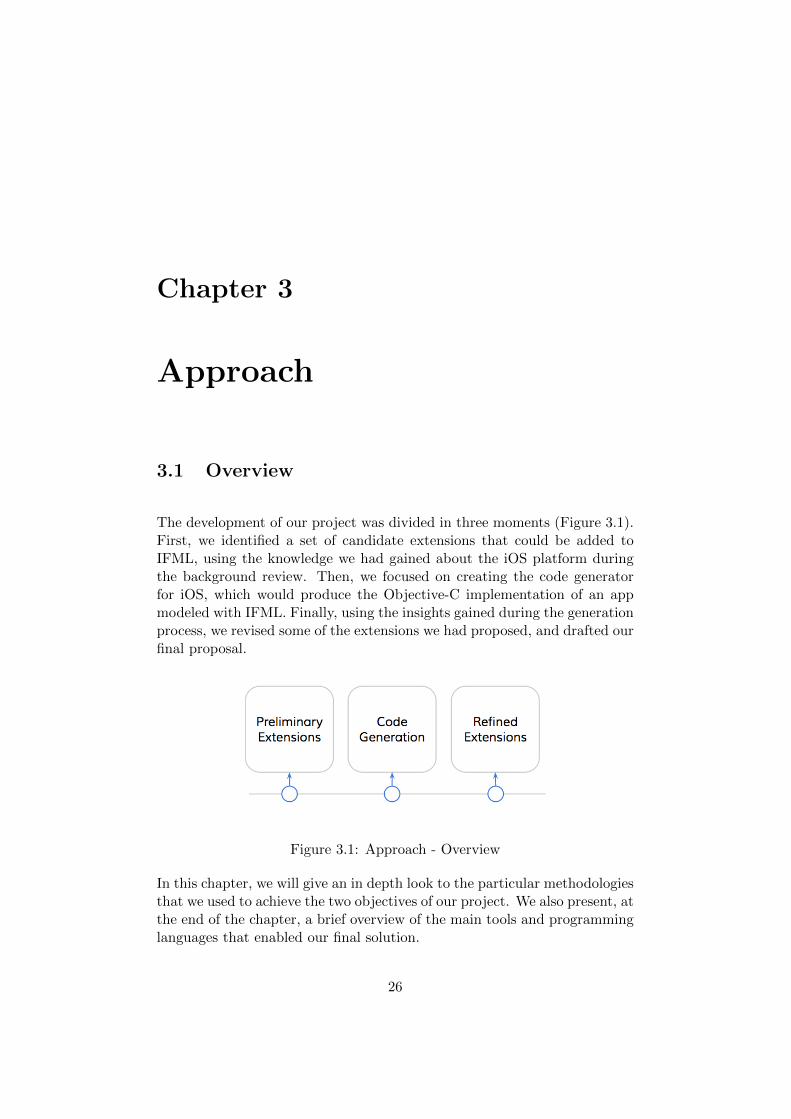
The development of our project was divided in three moments (Figure 3.1).First, we identified a set of candidate extensions that could be added toIFML, using the knowledge we had gained about the iOS platform duringthe background review. Then, we focused on creating the code generatorfor iOS, which would produce the Objective-C implementation of an appmodeled with IFML. Finally, using the insights gained during the generationprocess, we revised some of the extensions we had proposed, and drafted ourfinal proposal.
Figure 3.1: Approach - Overview
In this chapter, we will give an in depth look to the particular methodologiesthat we used to achieve the two objectives of our project. We also present, atthe end of the chapter, a brief overview of the main tools and programminglanguages that enabled our final solution.
26
3.2 Extensions
To tackle the first objective of the project, we strated by analyzing thetype of apps that could be built in iOS, and more specifically observingthe type of features and functionalities they offered. We began looking atthe gestures that were available, the types of sensors that could be used,and the strategies that enabled inter-app collaborations. We then looked atIFML to see if there was a way in which a software designer could expressthese traits in his models — whether a form could be submitted by shakingthe phone, or if a particular action could be triggered by an update on thedevice orientation. Every time we couldn’t find a way to represent one ofthese features, we proposed an extension.
The other place that proved to be a good source of inspiration, was theactual code generation effort that we had undergone to achieve the secondgoal of our project. The approach we followed in this case, was simple. Wereviewed all the assumptions that we had made about the implementationof a particular IFML entity in iOS, and then analyzed whether an extensioncould have helped to disambiguate the matter. For instance, while devel-oping the code generators, we assumed that all the user triggered events –Select Event, Submit Event, and plain View Element Events — were cap-tured after a user touch. This was an over simplification of what can beachieved in a mobile environment — where a user may touch, tap, slide andeven shake his device to trigger an event. In all these cases we added entitieswith more specific semantics, that would allow designers express their intentmore precisely – in our previous example, we added a set of extensions to theevent hierarchy of IFML. We repeated the same exercise with other entities,and produced the final extensions proposal.
To organize our extensions, we grouped them into three different packagesaccording to their scope, and the core entities they extended from. In thisway, the General Extensions Package contained classes that were valid be-yond a mobile environment, like an Application Lifecycle Event, a Multi-line Field or an Image Attribute. The Mobile Extensions Package instead,clustered entities that were more tightly coupled to the constraints and pos-sibilities offered by mobile technologies, like the tactile and sensor events.Finally, in the Private Extensions Package, we grouped classes that extendedthe Context entity of IFML, which as of this writing, is not allowed outsidea private scope by the IFML standard [21].
27
3.3 Code Generation
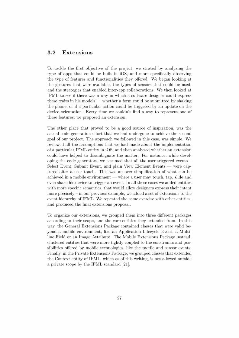
The diagram shown in Figure 3.2 provides a clear view of the methodologythat guided our work during this part of the project.
Figure 3.2: Approach - Code Generation
3.3.1 Prototype App
Our first step was to choose a suitable prototype that could guide the gen-eration process. We looked for an application that used a meaningful subsetof the IFML entities, and whose model had already been designed with themodel editor. After some analysis, we chose one of the sample applica-tions that shipped with the IFML Model Editor. We applied some minormodifications to its model, and then moved forward to provide an iOS im-plementation for it.
Choosing this prototype was very important. It defined which entities weresupported and which were not. But the next step, was the one that trulydefined the shape of our solution.
3.3.2 Target Architecture
We defined the architecture of the generated apps in two ways. First, we useda software driven approach to described the main application componentsand their relations. Then, we used model driven approach, to formalize thestructure of this architecture in a metamodel.
28
The software driven approach was concerned with creating a taxonomy forthe objects that composed the application, assigning responsibilities for eachof them, and describing the way different types of objects collaborate witheach other. In contrast, the model driven approach focused on representingthe application components at a level of abstraction that was farther awayfrom the implementation details.
This approach allowed us to think about the transition that takes the IFMLmodel of an application to its iOS implementation, as a two step process.First the IFML entities had to be mapped into the metamodel that definedthe target architecture — a Model to Model transformation. Then, themapped entities had to be translated into the code of the target platform— a Model to Text transformation.
In this way, our next step was to understand the equivalences between IFMLand the entities in the newly defined target metamodel.
3.3.3 Mappings
There were two ways in which we could perform the mapping between IFMLand the entities of the target metamodel. The first one, was to write a setof rules using a model transformation language like ATL. The second one,was a more flexible approach based on diagrams.
The first strategy had the advantage of being formal, allowing the modeltransformation to be done automatically through the tools provided by theEclipse Modeling Framework (EMF). On the other hand, it increased thetechnical demands of the project, reducing the time that we could devote toother aspects of the research.
The other strategy, instead, had the benefit of being lightweight and fasterto perform. On the flip side, however, it moved most of the transformationburden into the code generators, which instead of having to generate codeout of the entities of the target metamodel, had to do so from the entitiesof the IFML model.
At the end, we opted for a hybrid approach. We preserved the formality ofthe two step transformation process provided by the model driven approach,as a theoretical tool that described the shape of our solution. While theactual implementation was achieved by describing the mappings using a setof diagrams and placing all the transformation logic into the code generators.
29
Once the equivalences between IFML and the target architecture were wellunderstood, we focused on the code related tasks. Particularly, we set outto discover how much code had to be generated.
3.3.4 Static Library
To understand how much code had to be generated during the M2T trans-formation step, we started by analyzing the code of the prototype app. Weseparated the pieces of code that were model independent — those thatwould remain the same across the generated applications—, from those thatdepended on the input model. The model independent pieces were wrappedinto a static library; the other sections of code instead, were singled out asthe ones that would be dynamically generated by the code generators.
We wrapped the model independent pieces into a static library because inthis way we could reduce and simplify the code that had to be generated.The library contained a set of basic classes, a collection of default viewsand other utilities. The basic classes would be extended by the generatedcode, allowing us to factor out into parent classes all the complicated logicand control flow. The default views and the utilities instead, allowed usto provide the generated apps with a basic user interface, that will furtherreduce the time between modeling and the first compilation of the apps.Additionally, since the dependencies between the generated code and theclasses in the library were resolved at compilation time, we were able to testand debug the library independently, which gave us a lot of flexibility.
At the end of this stage, we had a good grasp of what needed to be generated,and could start working on two parallel fronts. One that was be focused inwriting and testing the code contained in the static library, and other thatfocused on the development of the actual generators.
3.3.5 Code Generator
There are several patterns that can be used to implement a code generationtool — Markus Voelter [25] has several good advices on this topic. In ourcase, we decided to use the “Template and Filtering” [25] approach. Inconsequence, all the generators we developed had a very similar logic. Theywould first query the IFML model, to find the subset of entities that wouldbe transformed, and then, through the usage of templates and simple logic,they would generate the target source code.
30
An important advantage we had, was given by the IFML metamodel, whichhad been developed using ECORE. This implied, that instead of having todeal with cumbersome and time consuming tasks like parsing the model file,and providing an object oriented representation of the elements in it, wecould use the APIs provided by the Eclipse Modeling Framework (EMF)1,which made trivial these operations.
Our technical stack was completed by Xtend2 — a dialect of Java, thatcompiles to regular Java code —. We chose this tool, to develop the actualgenerators because of its powerful template capabilities and very concretesyntax.
In combination, the EMF infrastructure, Xtend, and the “Template andFiltering” [25] strategy made the implementation of the transformation toolmuch easier, and kept the focus on the real objective: producing Objective-Ccode out of an IFML model.
The only caveat we found while using these tools, was the managementof static files. In our project this meant, copying into the final outputthe classes of the static library and a set of boilerplate files that remainedunchanged across the generated applications — e.g the Main file.
We addressed this issue through a combination of strategies. First, since thenumber of boilerplate files was not too high in our case, we added generatorswhose only purpose was to create the same files every time. As for thefiles in the static library, since they also had to be linked to the classes inthe generated code, we opted for a more robust strategy that involved theusage of cocoapods3 — a popular dependency manager for iOS and OSXdevelopment.
3.3.6 Integration Tools
The goal of this final step was to integrate the generated files into the toolsused by iOS developers. This implied the generation of the Xcode projectfile and the development of a script that retrieved the static library andlinked it to the generated project.
This additional effort allowed us iterate much faster in the development of
1 http://eclipse.org/modeling/emf/2 http://eclipse.org/xtend/3 http://cocoapods.org/
31
the generators. Instead of having to manually create a new Xcode4 projectand add the generated files along with the static library to it, we could onlyexecute the scripts and have it done for us in a couple of seconds.
Moreover, we could tighten up even more the final output project, so thatthe folder structure of the generated app will be indistinguishable from thestructure of an app that had been manually created.
3.3.7 Packaging
Up to this point, we had created three different tools that were tightlyrelated. First, the Code Generators, which had been distributed as a stan-dalone jar. The project builder script, which had been developed using ruby. And Finally, the Library Linker that would download the Static Libraryfrom a centralized repository and add it to the compilation path of thegenerated Xcode project, leveraging the capabilities offered by cocoapods.
The biggest issue caused by having these separate applications was usability.An IFML designer interested in generating the iOS version for one of hismodels, would have to launch each of these tools, execute them in the rightorder and remember to provide the appropriate parameters for each of them.To solve this issue, and ultimately, make the leap from IFML into iOS, asfrictionless as possible, we developed a desktop app with a graphic wizardto guide users through the generation process.
3.4 Tools
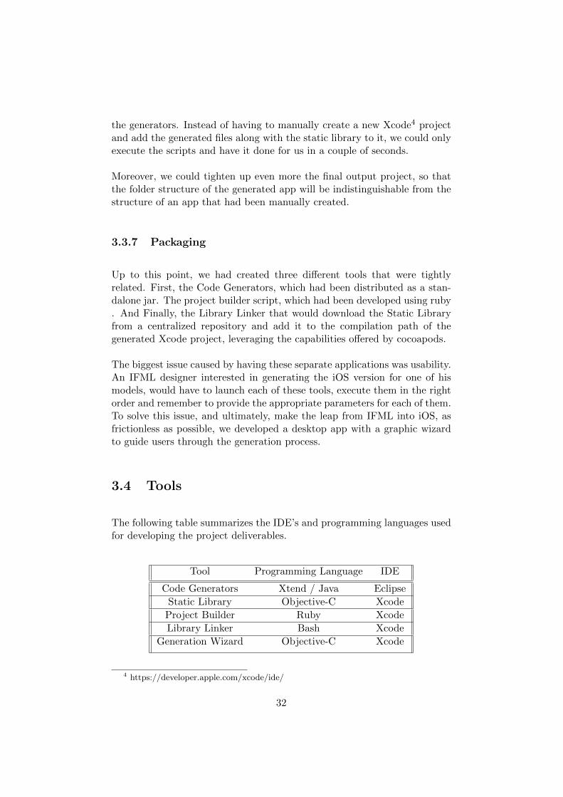
The following table summarizes the IDE’s and programming languages usedfor developing the project deliverables.
Tool Programming Language IDE
Code Generators Xtend / Java Eclipse
Static Library Objective-C Xcode
Project Builder Ruby Xcode
Library Linker Bash Xcode
Generation Wizard Objective-C Xcode
4 https://developer.apple.com/xcode/ide/
32
Chapter 4
Extensions
Currently, IFML provides software designers with a set of entities that canbe used to model desktop, web and even the fundamental aspects of mobileapplications. There are, however, several features of the mobile environ-ment that are not covered yet by the language. For instance, a softwaredesigner doesn’t have a way to query the hardware capabilities of the de-vice in which his application is running on, to understand which sensorsare available or what communication networks are currently active. Simi-larly, the existing Event architecture of IFML doesn’t consider interactionsbeyond simple mouse and keyboard events, leaving uncovered tactile andsensor driven events. Finally, there are few, and very general, entities thatcan be used to model apps that can cope with the changing nature of themobile context or blend nicely with the resource optimization strategies usedby modern mobile operating systems.
For this reason, our goal during this part of the project was to provide asuitable set of extensions for IFML, that would allow software designersmodel modern mobile applications, considering the particular requirementsthat arise in this platform. Similarly, these extensions also had the benefitof potentially increase the effectivety of future code generators, since havingmore specific entities mean that better assumptions can be made regardingthe functionalities expressed by software designers in their models.
As a result, we proposed 90 extensions that we divided into three packages:the General Extensions Package, the Mobile Extensions Package, and thePrivate Extensions Package. Figure 4.1, shows these packages, the numberof entities they contained and the IFML entity they extended from. Asfor the specific extensions they included, in the next sections we provide a
33
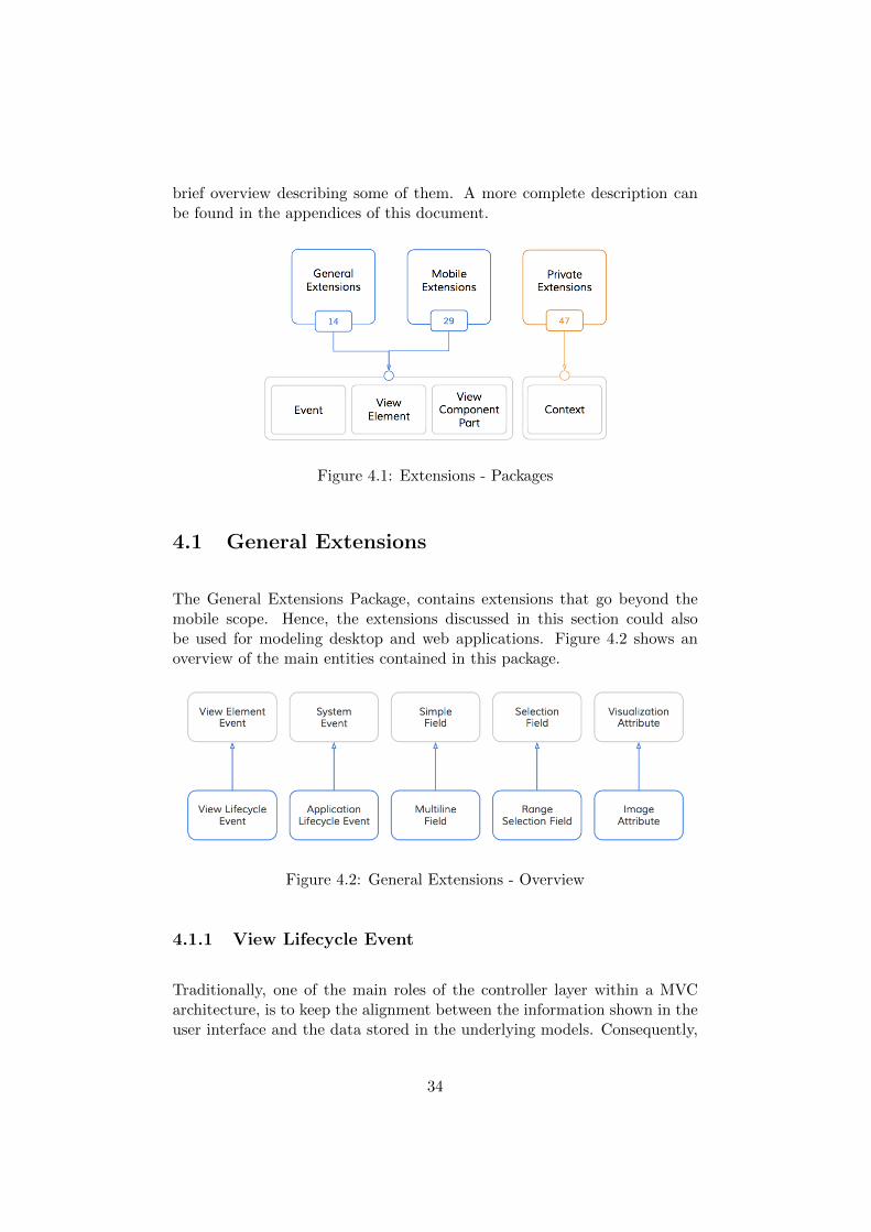
brief overview describing some of them. A more complete description canbe found in the appendices of this document.
Figure 4.1: Extensions - Packages
4.1 General Extensions
The General Extensions Package, contains extensions that go beyond themobile scope. Hence, the extensions discussed in this section could alsobe used for modeling desktop and web applications. Figure 4.2 shows anoverview of the main entities contained in this package.
Figure 4.2: General Extensions - Overview
4.1.1 View Lifecycle Event
Traditionally, one of the main roles of the controller layer within a MVCarchitecture, is to keep the alignment between the information shown in theuser interface and the data stored in the underlying models. Consequently,
34
this synchronicity needs to be enforced by the controller throughout thelifespan of the view it manages, including the following milestones:
• The creation and allocation of a view in memory.
• After a user interacts with the view aiming to change the state of themodels.
• Every time a view is displayed, after the user has visited other sectionsof the app.
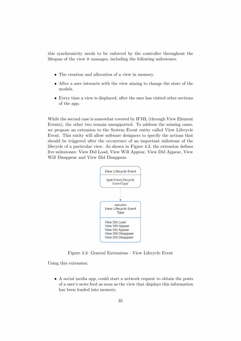
While the second case is somewhat covered by IFML (through View ElementEvents), the other two remain unsupported. To address the missing cases,we propose an extension to the System Event entity called View LifecycleEvent. This entity will allow software designers to specify the actions thatshould be triggered after the occurrence of an important milestone of thelifecycle of a particular view. As shown in Figure 4.3, the extension definesfive milestones: View Did Load, View Will Appear, View Did Appear, ViewWill Disappear and View Did Disappear.
Figure 4.3: General Extensions - View Lifecycle Event
Using this extension:
• A social media app, could start a network request to obtain the postsof a user’s news feed as soon as the view that displays this informationhas been loaded into memory.
35
• A task manager app, could update the main task list to reflect thechanges applied by the user in a different section of the app.
4.1.2 Application Lifecycle Event
In order to optimize resource usage and provide the possibility of executingseveral applications concurrently, operating systems use several strategies.One of this strategies consist in assigning different states to the runningapplications depending on whether they are running in the foreground or inthe background [7]. In consequence, to guarantee the best user experience,applications must supply mechanisms to take appropriated actions afterbeing notified about a change in their state.
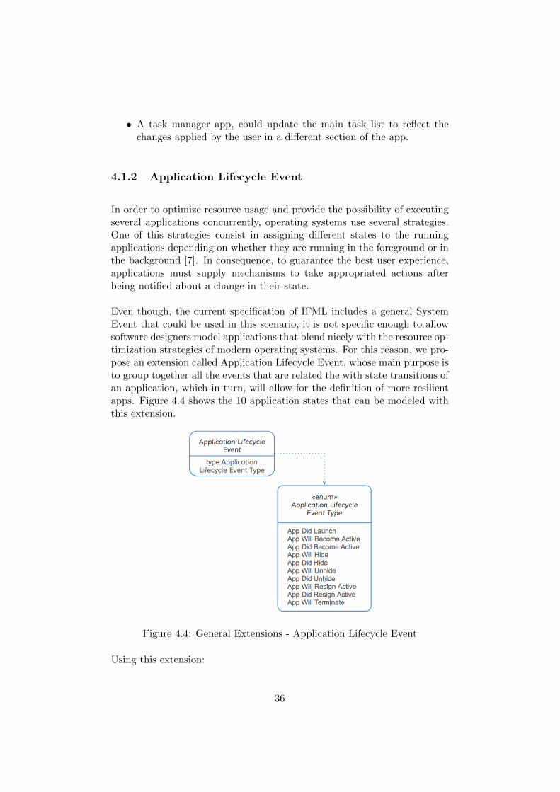
Even though, the current specification of IFML includes a general SystemEvent that could be used in this scenario, it is not specific enough to allowsoftware designers model applications that blend nicely with the resource op-timization strategies of modern operating systems. For this reason, we pro-pose an extension called Application Lifecycle Event, whose main purpose isto group together all the events that are related the with state transitions ofan application, which in turn, will allow for the definition of more resilientapps. Figure 4.4 shows the 10 application states that can be modeled withthis extension.
Figure 4.4: General Extensions - Application Lifecycle Event
Using this extension:
36
• A note taking application can save locally the user’s work, once it isnotified about being swapped into a background state, foreseeing apossible future termination.
• A productivity app, that allows several users to collaborate in thecreation of a document, may notify the server before a user terminatesthe application, so push notifications are suspended for this user.
• A casual gaming app, may choose to pause the game timers when theapplication is moving into the background.
4.1.3 Multiline Field
Currently a software designer doesn’t have a way for indicating if a SimpleField may allow single or multiple-line inputs, yet this distinction may leadto very different implementations. To disambiguate these cases, an extensioncalled Multiline Field is proposed.
Using this extension
• A social network may model the user registration form using a SimpleField for capturing the user’s name, and a Multiline Field for capturingthe user’s bio.
• An ecommerce app may use a Multiline Field to allow users writereviews about the products offered in the platform.
4.1.4 Range Selection Field
Range Selection Fields are meant to allow users select a particular valuewithin a range of discrete or continuous values. To fully model this type offields, this entity contains the following attributes
• minValue: the lower boundary of the range
• maxValue: the upper boundary of the range
• stepValue: the increment by which a user may update the field value.
Using this extension:
37
• An application for order processing may use a Range Selection Fieldwith its minValue set to 0, a maxValue equals to 100 to model adiscount percentage field.
• A hotel booking application, may use a Range Selection Field with itsstepValue set to 1, to model the number of guests that will be stayingin a room.
4.1.5 Image Attribute
Currently designers don’t have a way to differentiate between a VisualizationAttribute that needs to be rendered as text from a piece of data that needsto be shown as an image. To disambiguate these cases, an extension of theVisualization Attribute, called Image Attribute was be introduced.
Using this extension,
• An email application, may model the user profile section using a Visu-alization Attribute for the user’s name field, and an Image Attributefor the user’s picture.
• An ecommerce application, may model a catalog of products usinga List View Component that shows for each product a VisualizationAttribute for the product’s name, and an Image Attribute for theproduct’s picture.
38
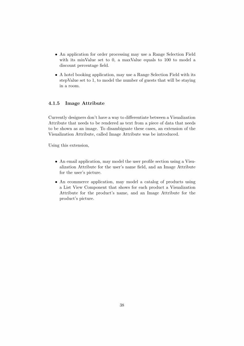
4.2 Mobile Extensions
One of the strongest appeals of mobile applications comes from their abilityto exploit the interaction capabilities of the devices they are executed on.For this reason, allowing users to interact with an application using tactilegestures or by physically moving their devices has become an importantconcern of the front end development of mobile apps. In contrast, one of thebiggest challenges faced by developers comes from the inherently tougherenvironment in which mobile applications are executed on.
While IFML allows software designers to model certain user interactions, andrespond to some system triggered events, there are still several uncoveredaspects that are needed to enable the definition of resilient applications thatcan take full advantage of the interaction capabilities offered by the mobileplatforms.
On the other hand, mobile operating systems have an active role and interactfrequently with applications. Hence, mobile operating systems are not onlyin charge of managing access to shared resources like memory and storage,but also of tasks like delivering sensor readings to the applications thatrequire them. Additionally, due to the relatively short amount of availableresources in mobile platforms and the optimization strategies put in placeby the operating systems to cope with such scarcity, mobile apps need tobe able to receive system notifications and react appropriately to them inorder to provide a consistent and reliable user experience.
System Events in IFML are meant to model occurrences that are not directlyinitiated by the user, but that are instead triggered directly by the operatingsystem. Even though these general events can be used to model some ofthe previously described cases, a more subtle taxonomy will allow softwaredesigners to specify how their mobile applications should react to specificoccurrences. In particular, we propose a taxonomy shaped by two entities:Mobile Sensor Event, and Mobile Resource Events.
Mobile Sensor Events model all occurrences generated by the device sensors.Mobile Resource Events instead describe the notifications triggered by theoperating system regarding the shortage and changes on the availability ofcertain shared resource. Furthermore, we have proposed an extension forthe View Container class of IFML, called Screen, that represents each of thescenes that makeup the user interface of a mobile application. Figure 4.5,illustrates the main extensions of this package, while the following sectionsdescribe briefly their purpose and utility.
39
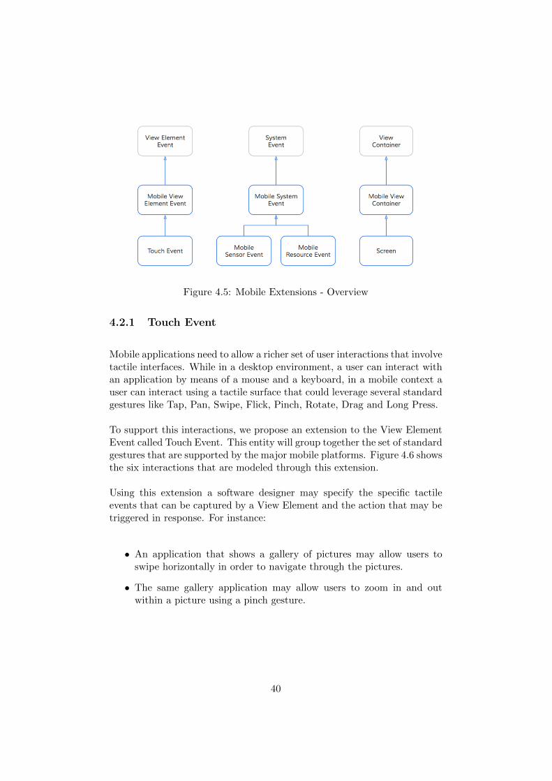
Figure 4.5: Mobile Extensions - Overview
4.2.1 Touch Event
Mobile applications need to allow a richer set of user interactions that involvetactile interfaces. While in a desktop environment, a user can interact withan application by means of a mouse and a keyboard, in a mobile context auser can interact using a tactile surface that could leverage several standardgestures like Tap, Pan, Swipe, Flick, Pinch, Rotate, Drag and Long Press.
To support this interactions, we propose an extension to the View ElementEvent called Touch Event. This entity will group together the set of standardgestures that are supported by the major mobile platforms. Figure 4.6 showsthe six interactions that are modeled through this extension.
Using this extension a software designer may specify the specific tactileevents that can be captured by a View Element and the action that may betriggered in response. For instance:
• An application that shows a gallery of pictures may allow users toswipe horizontally in order to navigate through the pictures.
• The same gallery application may allow users to zoom in and outwithin a picture using a pinch gesture.
40
Figure 4.6: Mobile Extensions - Touch Event Hierarchy
4.2.2 Mobile Sensor Event
Mobile applications need to allow interactions with the outside world beyonduser inputs, that is considering as sources of events other agents like thedevice sensors. The events produced by these sensors are usually captured bythe operating system and delivered to the application upon user permission.For this reason, we propose an extension to the System Event called SensorEvent that identifies three general categories of events, namely: ProximityEvent, Location Events and Motion Events.
Figure 4.7: Mobile Extensions - Mobile Sensor Hierarchy
• Proximity Events are produced by the proximity sensor of the device,is frequently used by applications that require the user to place thedevice near to his ear such as telephone apps.
• Location Events refer to changes in the geographical position of theuser. They are captured by the device GPS and are frequently usedin applications that involve maps and navigation.
41
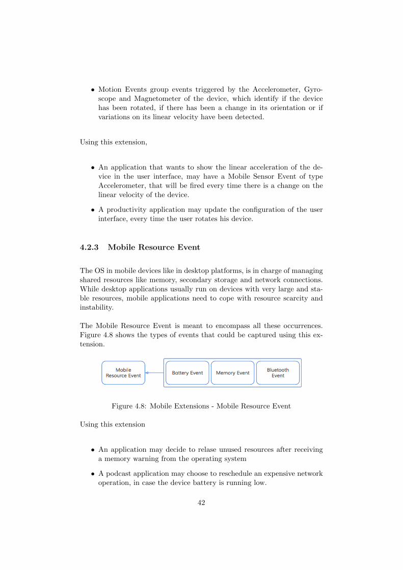
• Motion Events group events triggered by the Accelerometer, Gyro-scope and Magnetometer of the device, which identify if the devicehas been rotated, if there has been a change in its orientation or ifvariations on its linear velocity have been detected.
Using this extension,
• An application that wants to show the linear acceleration of the de-vice in the user interface, may have a Mobile Sensor Event of typeAccelerometer, that will be fired every time there is a change on thelinear velocity of the device.
• A productivity application may update the configuration of the userinterface, every time the user rotates his device.
4.2.3 Mobile Resource Event
The OS in mobile devices like in desktop platforms, is in charge of managingshared resources like memory, secondary storage and network connections.While desktop applications usually run on devices with very large and sta-ble resources, mobile applications need to cope with resource scarcity andinstability.
The Mobile Resource Event is meant to encompass all these occurrences.Figure 4.8 shows the types of events that could be captured using this ex-tension.
Figure 4.8: Mobile Extensions - Mobile Resource Event
Using this extension
• An application may decide to relase unused resources after receivinga memory warning from the operating system
• A podcast application may choose to reschedule an expensive networkoperation, in case the device battery is running low.
42
4.2.4 Screen
Akin to the Window extension of IFML, the Screen entity is aimed to rep-resent the basic container unit of a mobile application. Furthermore, tocover the most frequent usage scenarios of this entity, we have given it twoattributes:
• isModal: To explicitly model wether a screen should be shown modallyor modeless, software designers may update the Boolean value of thisattribute.
• hasNavBar: While some platforms like Android use default navigationstacks to keep track of the screens that have been visisted by theuser, other platforms like iOS, require an explicit declaration. For thisreason, the Screen Entity contains a hasNavigationBar attribute thatallows designers to declare whether a particular screen should be partof a navigation stack.
Using this extension,
• A newsreader app, may model the share section of the application asa modal Screen to streamline the social features of the app.
• The Window containers of the dictionary app that we introduced inChapter 2, will be replaced by Screens, which will allow us to specifyaspects like back-navigation through simple attribute values.
43
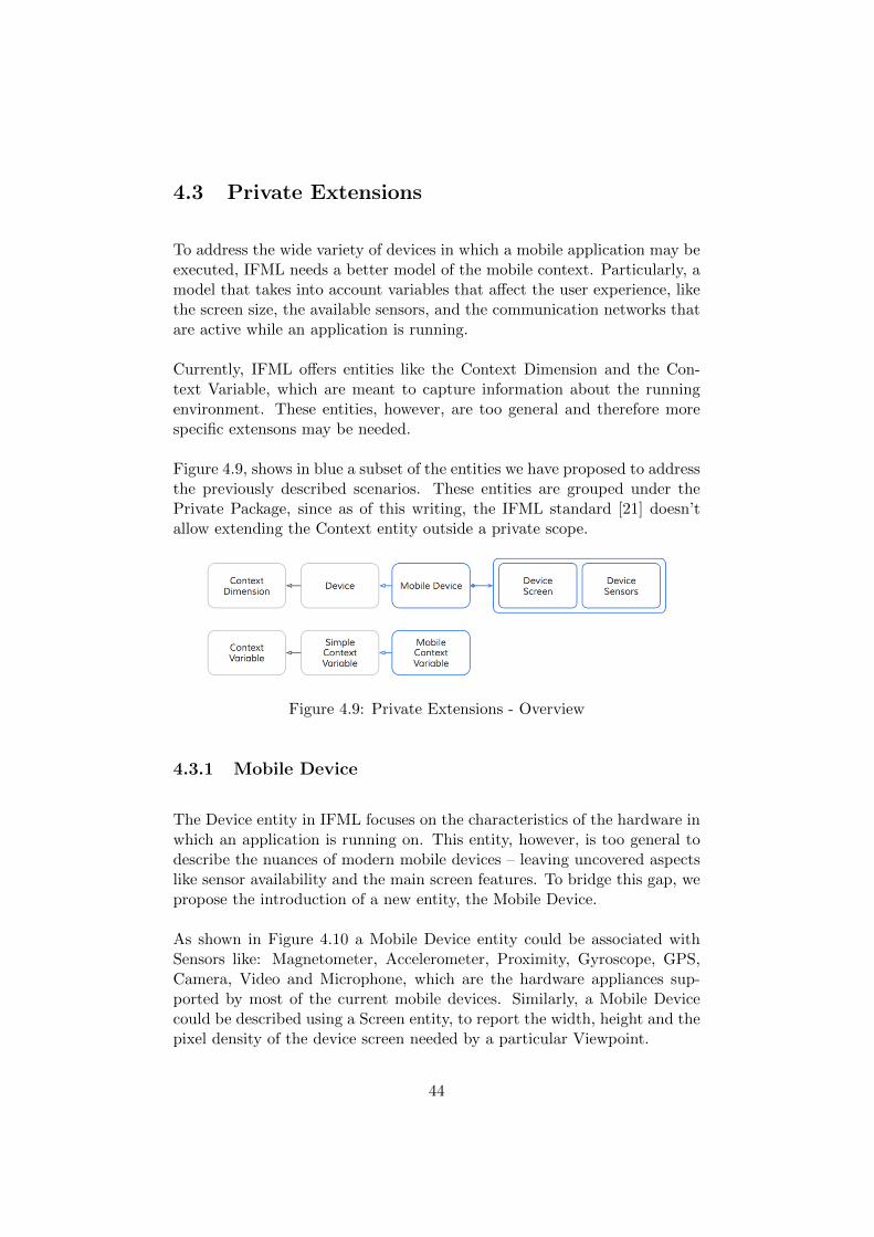
4.3 Private Extensions
To address the wide variety of devices in which a mobile application may beexecuted, IFML needs a better model of the mobile context. Particularly, amodel that takes into account variables that affect the user experience, likethe screen size, the available sensors, and the communication networks thatare active while an application is running.
Currently, IFML offers entities like the Context Dimension and the Con-text Variable, which are meant to capture information about the runningenvironment. These entities, however, are too general and therefore morespecific extensons may be needed.
Figure 4.9, shows in blue a subset of the entities we have proposed to addressthe previously described scenarios. These entities are grouped under thePrivate Package, since as of this writing, the IFML standard [21] doesn’tallow extending the Context entity outside a private scope.
Figure 4.9: Private Extensions - Overview
4.3.1 Mobile Device
The Device entity in IFML focuses on the characteristics of the hardware inwhich an application is running on. This entity, however, is too general todescribe the nuances of modern mobile devices – leaving uncovered aspectslike sensor availability and the main screen features. To bridge this gap, wepropose the introduction of a new entity, the Mobile Device.
As shown in Figure 4.10 a Mobile Device entity could be associated withSensors like: Magnetometer, Accelerometer, Proximity, Gyroscope, GPS,Camera, Video and Microphone, which are the hardware appliances sup-ported by most of the current mobile devices. Similarly, a Mobile Devicecould be described using a Screen entity, to report the width, height and thepixel density of the device screen needed by a particular Viewpoint.
44
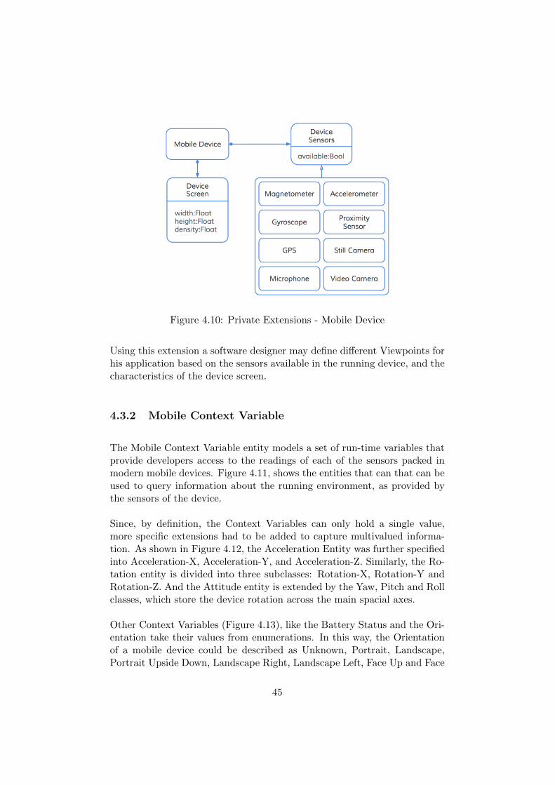
Figure 4.10: Private Extensions - Mobile Device
Using this extension a software designer may define different Viewpoints forhis application based on the sensors available in the running device, and thecharacteristics of the device screen.
4.3.2 Mobile Context Variable
The Mobile Context Variable entity models a set of run-time variables thatprovide developers access to the readings of each of the sensors packed inmodern mobile devices. Figure 4.11, shows the entities that can that can beused to query information about the running environment, as provided bythe sensors of the device.
Since, by definition, the Context Variables can only hold a single value,more specific extensions had to be added to capture multivalued informa-tion. As shown in Figure 4.12, the Acceleration Entity was further specifiedinto Acceleration-X, Acceleration-Y, and Acceleration-Z. Similarly, the Ro-tation entity is divided into three subclasses: Rotation-X, Rotation-Y andRotation-Z. And the Attitude entity is extended by the Yaw, Pitch and Rollclasses, which store the device rotation across the main spacial axes.
Other Context Variables (Figure 4.13), like the Battery Status and the Ori-entation take their values from enumerations. In this way, the Orientationof a mobile device could be described as Unknown, Portrait, Landscape,Portrait Upside Down, Landscape Right, Landscape Left, Face Up and Face
45
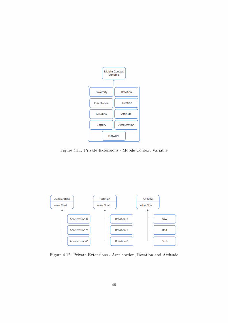
Figure 4.11: Private Extensions - Mobile Context Variable
Figure 4.12: Private Extensions - Acceleration, Rotation and Attitude
46
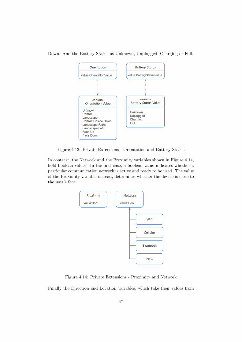
Down. And the Battery Status as Unknown, Unplugged, Charging or Full.
Figure 4.13: Private Extensions - Orientation and Battery Status
In contrast, the Network and the Proximity variables shown in Figure 4.14,hold boolean values. In the first case, a boolean value indicates whether aparticular communication network is active and ready to be used. The valueof the Proximity variable instead, determines whether the device is close tothe user’s face.
Figure 4.14: Private Extensions - Proximity and Network
Finally the Direction and Location variables, which take their values from
47
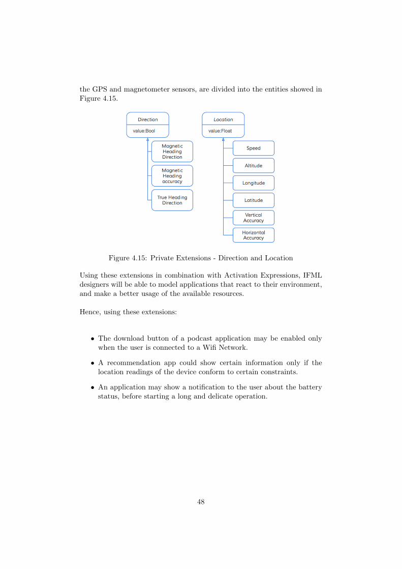
the GPS and magnetometer sensors, are divided into the entities showed inFigure 4.15.
Figure 4.15: Private Extensions - Direction and Location
Using these extensions in combination with Activation Expressions, IFMLdesigners will be able to model applications that react to their environment,and make a better usage of the available resources.
Hence, using these extensions:
• The download button of a podcast application may be enabled onlywhen the user is connected to a Wifi Network.
• A recommendation app could show certain information only if thelocation readings of the device conform to certain constraints.
• An application may show a notification to the user about the batterystatus, before starting a long and delicate operation.
48
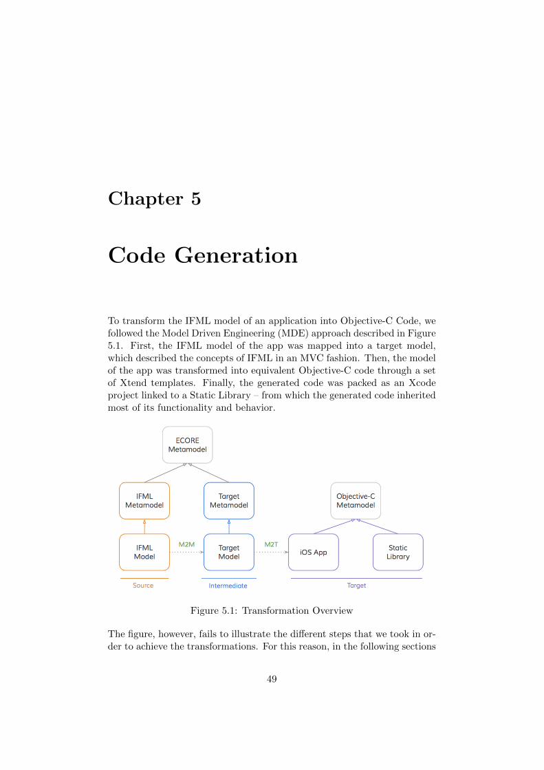
Chapter 5
Code Generation
To transform the IFML model of an application into Objective-C Code, wefollowed the Model Driven Engineering (MDE) approach described in Figure5.1. First, the IFML model of the app was mapped into a target model,which described the concepts of IFML in an MVC fashion. Then, the modelof the app was transformed into equivalent Objective-C code through a setof Xtend templates. Finally, the generated code was packed as an Xcodeproject linked to a Static Library – from which the generated code inheritedmost of its functionality and behavior.
Figure 5.1: Transformation Overview
The figure, however, fails to illustrate the different steps that we took in or-der to achieve the transformations. For this reason, in the following sections
49
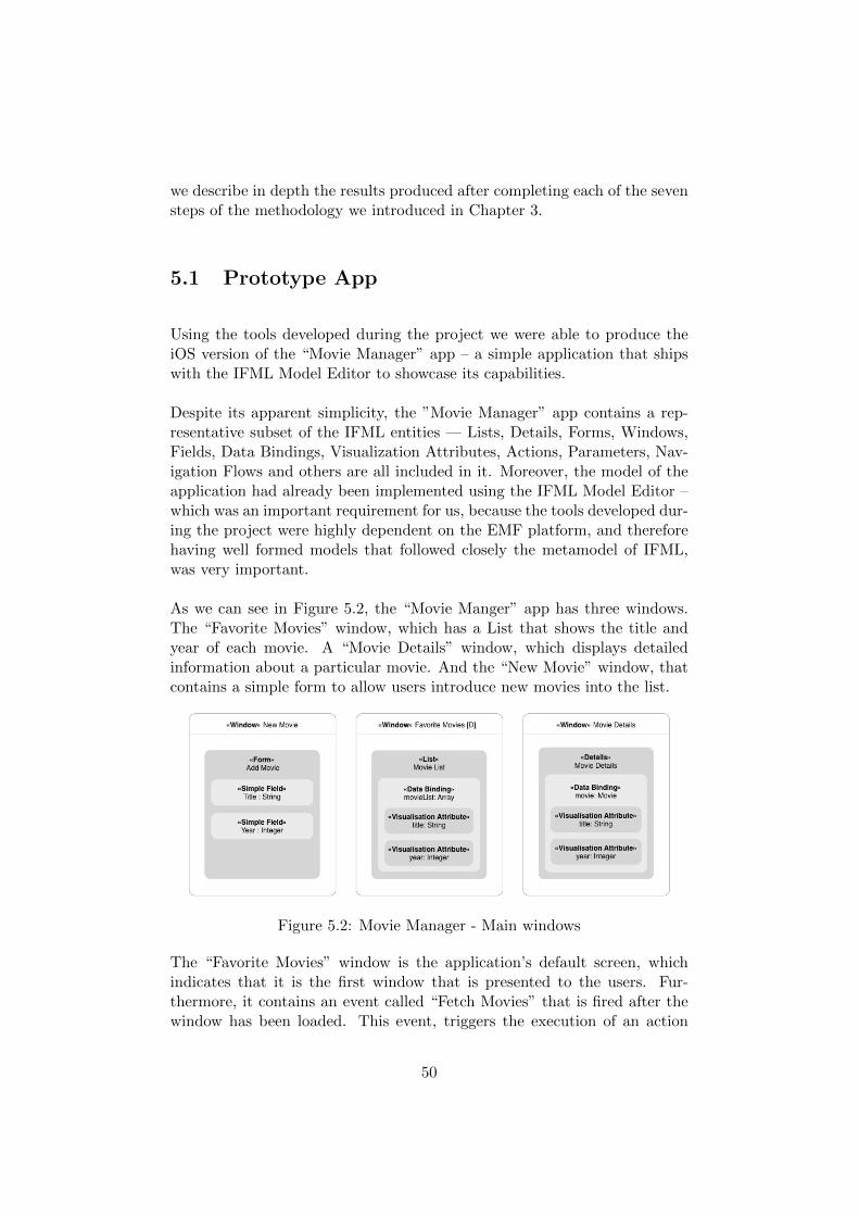
we describe in depth the results produced after completing each of the sevensteps of the methodology we introduced in Chapter 3.
5.1 Prototype App
Using the tools developed during the project we were able to produce theiOS version of the “Movie Manager” app – a simple application that shipswith the IFML Model Editor to showcase its capabilities.
Despite its apparent simplicity, the ”Movie Manager” app contains a rep-resentative subset of the IFML entities — Lists, Details, Forms, Windows,Fields, Data Bindings, Visualization Attributes, Actions, Parameters, Nav-igation Flows and others are all included in it. Moreover, the model of theapplication had already been implemented using the IFML Model Editor –which was an important requirement for us, because the tools developed dur-ing the project were highly dependent on the EMF platform, and thereforehaving well formed models that followed closely the metamodel of IFML,was very important.
As we can see in Figure 5.2, the “Movie Manger” app has three windows.The “Favorite Movies” window, which has a List that shows the title andyear of each movie. A “Movie Details” window, which displays detailedinformation about a particular movie. And the “New Movie” window, thatcontains a simple form to allow users introduce new movies into the list.
Figure 5.2: Movie Manager - Main windows
The “Favorite Movies” window is the application’s default screen, whichindicates that it is the first window that is presented to the users. Fur-thermore, it contains an event called “Fetch Movies” that is fired after thewindow has been loaded. This event, triggers the execution of an action
50
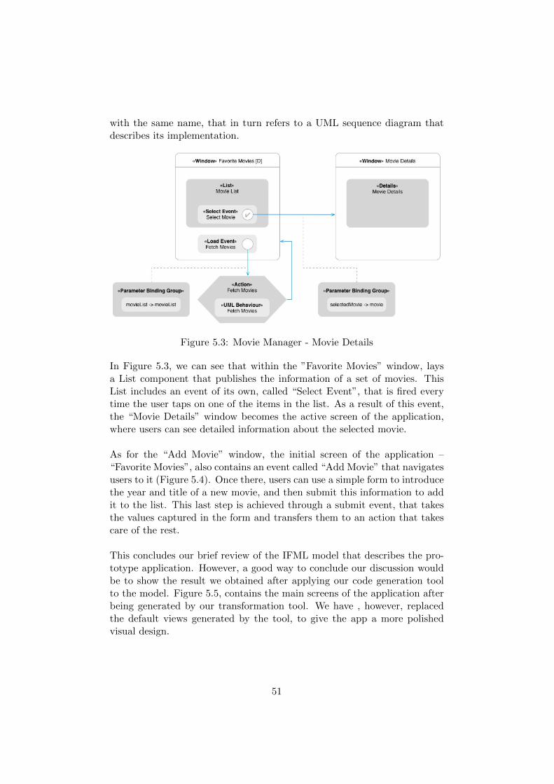
with the same name, that in turn refers to a UML sequence diagram thatdescribes its implementation.
Figure 5.3: Movie Manager - Movie Details
In Figure 5.3, we can see that within the ”Favorite Movies” window, laysa List component that publishes the information of a set of movies. ThisList includes an event of its own, called “Select Event”, that is fired everytime the user taps on one of the items in the list. As a result of this event,the “Movie Details” window becomes the active screen of the application,where users can see detailed information about the selected movie.
As for the “Add Movie” window, the initial screen of the application –“Favorite Movies”, also contains an event called “Add Movie” that navigatesusers to it (Figure 5.4). Once there, users can use a simple form to introducethe year and title of a new movie, and then submit this information to addit to the list. This last step is achieved through a submit event, that takesthe values captured in the form and transfers them to an action that takescare of the rest.
This concludes our brief review of the IFML model that describes the pro-totype application. However, a good way to conclude our discussion wouldbe to show the result we obtained after applying our code generation toolto the model. Figure 5.5, contains the main screens of the application afterbeing generated by our transformation tool. We have , however, replacedthe default views generated by the tool, to give the app a more polishedvisual design.
51
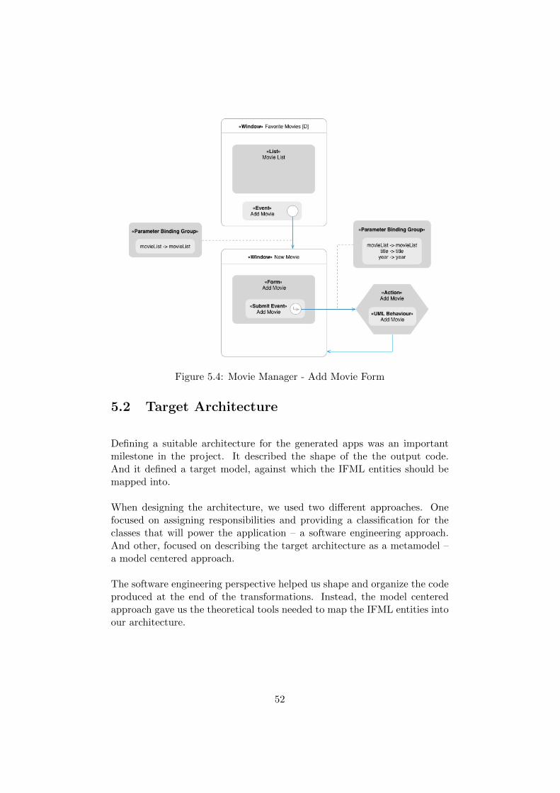
Figure 5.4: Movie Manager - Add Movie Form
5.2 Target Architecture
Defining a suitable architecture for the generated apps was an importantmilestone in the project. It described the shape of the the output code.And it defined a target model, against which the IFML entities should bemapped into.
When designing the architecture, we used two different approaches. Onefocused on assigning responsibilities and providing a classification for theclasses that will power the application – a software engineering approach.And other, focused on describing the target architecture as a metamodel –a model centered approach.
The software engineering perspective helped us shape and organize the codeproduced at the end of the transformations. Instead, the model centeredapproach gave us the theoretical tools needed to map the IFML entities intoour architecture.
52
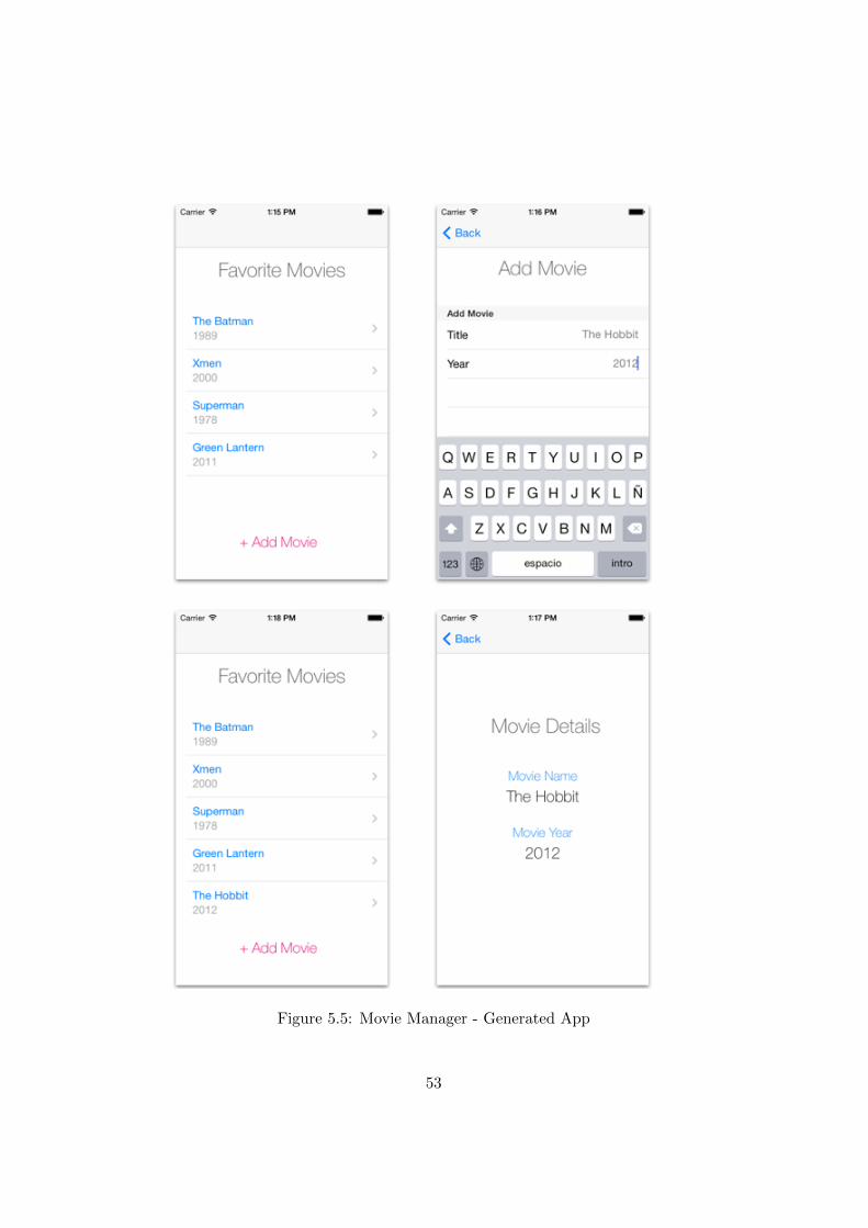
Figure 5.5: Movie Manager - Generated App
53
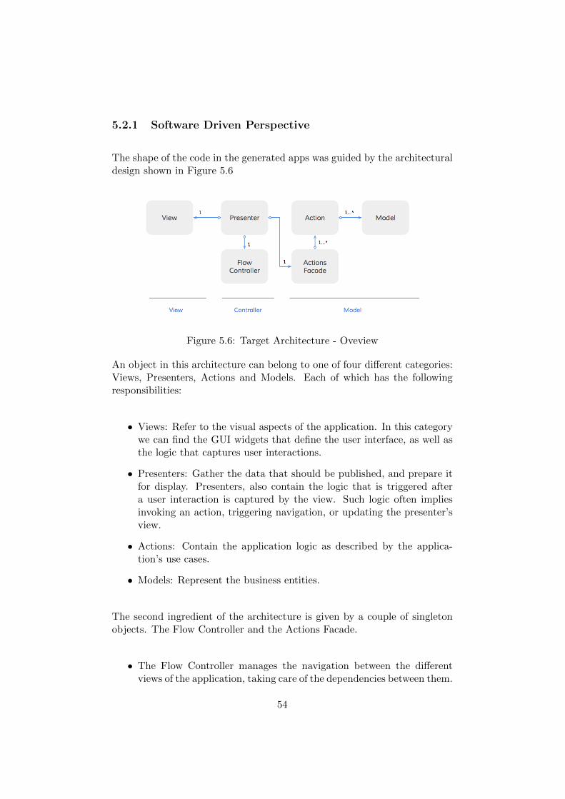
5.2.1 Software Driven Perspective
The shape of the code in the generated apps was guided by the architecturaldesign shown in Figure 5.6
Figure 5.6: Target Architecture - Oveview
An object in this architecture can belong to one of four different categories:Views, Presenters, Actions and Models. Each of which has the followingresponsibilities:
• Views: Refer to the visual aspects of the application. In this categorywe can find the GUI widgets that define the user interface, as well asthe logic that captures user interactions.
• Presenters: Gather the data that should be published, and prepare itfor display. Presenters, also contain the logic that is triggered aftera user interaction is captured by the view. Such logic often impliesinvoking an action, triggering navigation, or updating the presenter’sview.
• Actions: Contain the application logic as described by the applica-tion’s use cases.
• Models: Represent the business entities.
The second ingredient of the architecture is given by a couple of singletonobjects. The Flow Controller and the Actions Facade.
• The Flow Controller manages the navigation between the differentviews of the application, taking care of the dependencies between them.
54
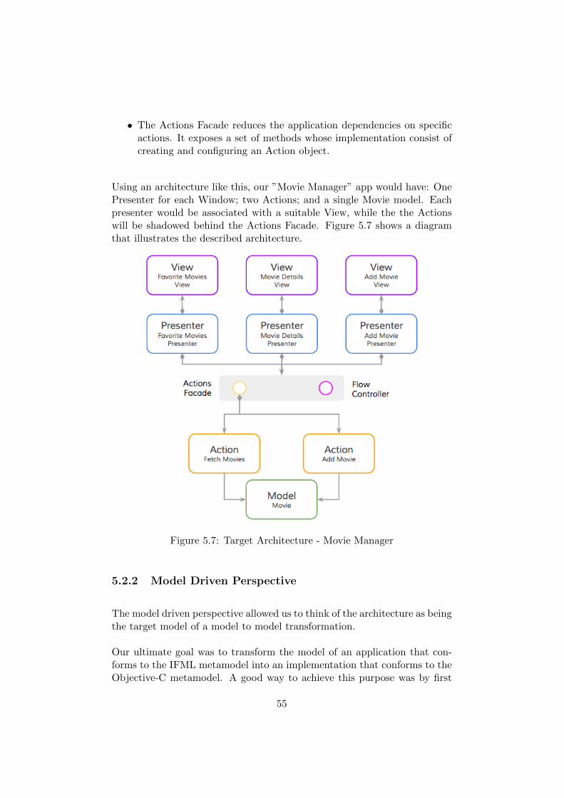
• The Actions Facade reduces the application dependencies on specificactions. It exposes a set of methods whose implementation consist ofcreating and configuring an Action object.
Using an architecture like this, our ”Movie Manager” app would have: OnePresenter for each Window; two Actions; and a single Movie model. Eachpresenter would be associated with a suitable View, while the the Actionswill be shadowed behind the Actions Facade. Figure 5.7 shows a diagramthat illustrates the described architecture.
Figure 5.7: Target Architecture - Movie Manager
5.2.2 Model Driven Perspective
The model driven perspective allowed us to think of the architecture as beingthe target model of a model to model transformation.
Our ultimate goal was to transform the model of an application that con-forms to the IFML metamodel into an implementation that conforms to theObjective-C metamodel. A good way to achieve this purpose was by first
55
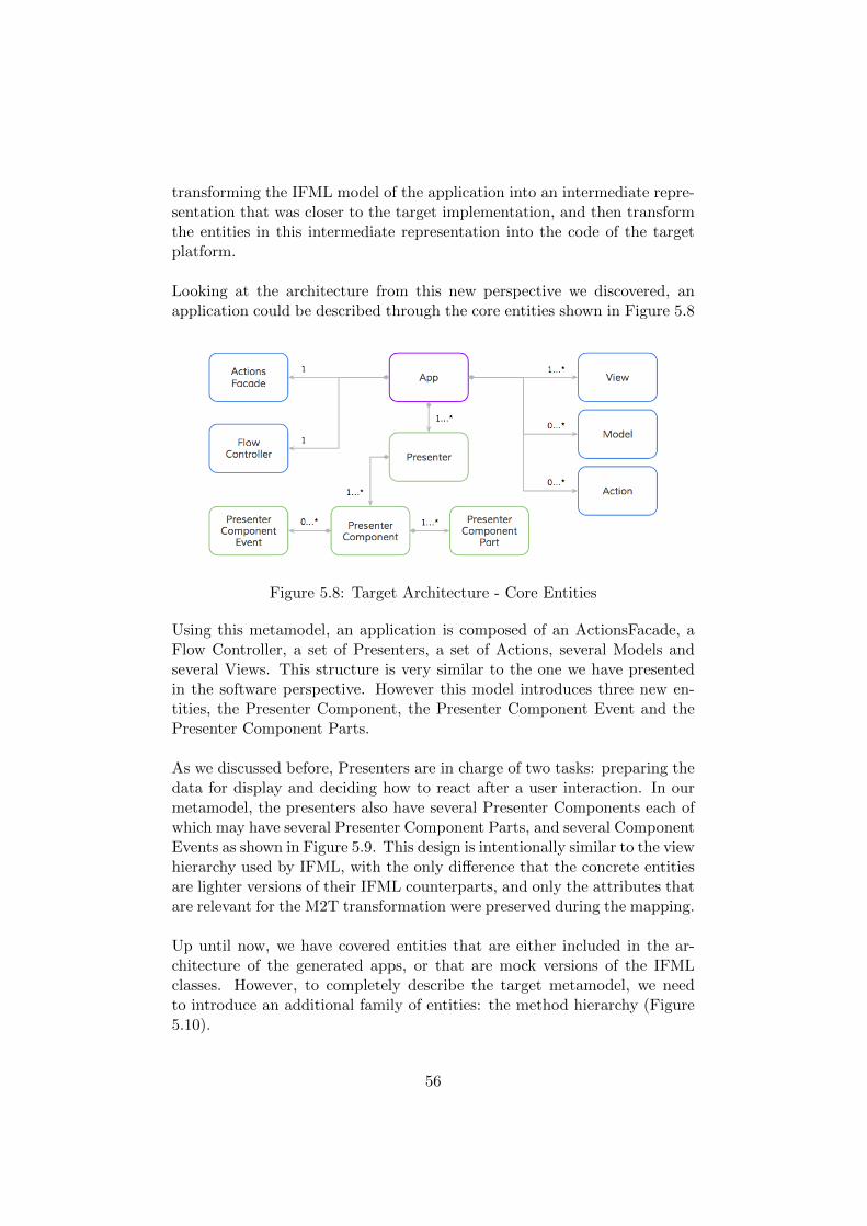
transforming the IFML model of the application into an intermediate repre-sentation that was closer to the target implementation, and then transformthe entities in this intermediate representation into the code of the targetplatform.
Looking at the architecture from this new perspective we discovered, anapplication could be described through the core entities shown in Figure 5.8
Figure 5.8: Target Architecture - Core Entities
Using this metamodel, an application is composed of an ActionsFacade, aFlow Controller, a set of Presenters, a set of Actions, several Models andseveral Views. This structure is very similar to the one we have presentedin the software perspective. However this model introduces three new en-tities, the Presenter Component, the Presenter Component Event and thePresenter Component Parts.
As we discussed before, Presenters are in charge of two tasks: preparing thedata for display and deciding how to react after a user interaction. In ourmetamodel, the presenters also have several Presenter Components each ofwhich may have several Presenter Component Parts, and several ComponentEvents as shown in Figure 5.9. This design is intentionally similar to the viewhierarchy used by IFML, with the only difference that the concrete entitiesare lighter versions of their IFML counterparts, and only the attributes thatare relevant for the M2T transformation were preserved during the mapping.
Up until now, we have covered entities that are either included in the ar-chitecture of the generated apps, or that are mock versions of the IFMLclasses. However, to completely describe the target metamodel, we needto introduce an additional family of entities: the method hierarchy (Figure5.10).
56
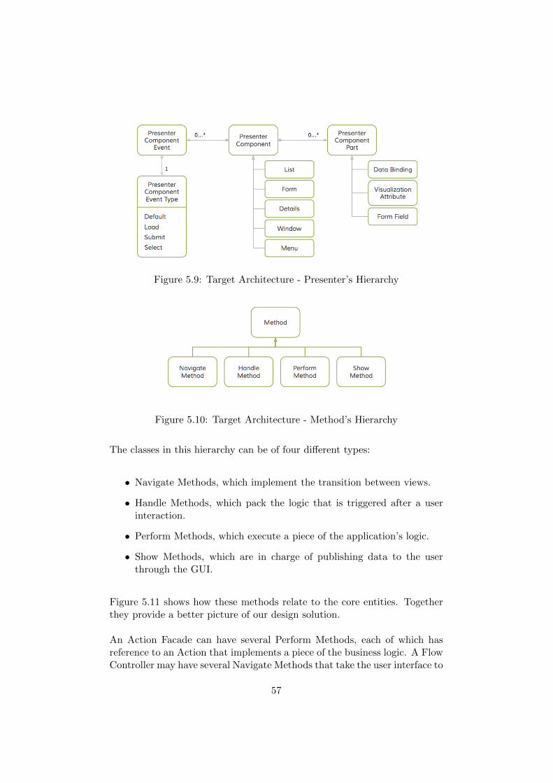
Figure 5.9: Target Architecture - Presenter’s Hierarchy
Figure 5.10: Target Architecture - Method’s Hierarchy
The classes in this hierarchy can be of four different types:
• Navigate Methods, which implement the transition between views.
• Handle Methods, which pack the logic that is triggered after a userinteraction.
• Perform Methods, which execute a piece of the application’s logic.
• Show Methods, which are in charge of publishing data to the userthrough the GUI.
Figure 5.11 shows how these methods relate to the core entities. Togetherthey provide a better picture of our design solution.
An Action Facade can have several Perform Methods, each of which hasreference to an Action that implements a piece of the business logic. A FlowController may have several Navigate Methods that take the user interface to
57
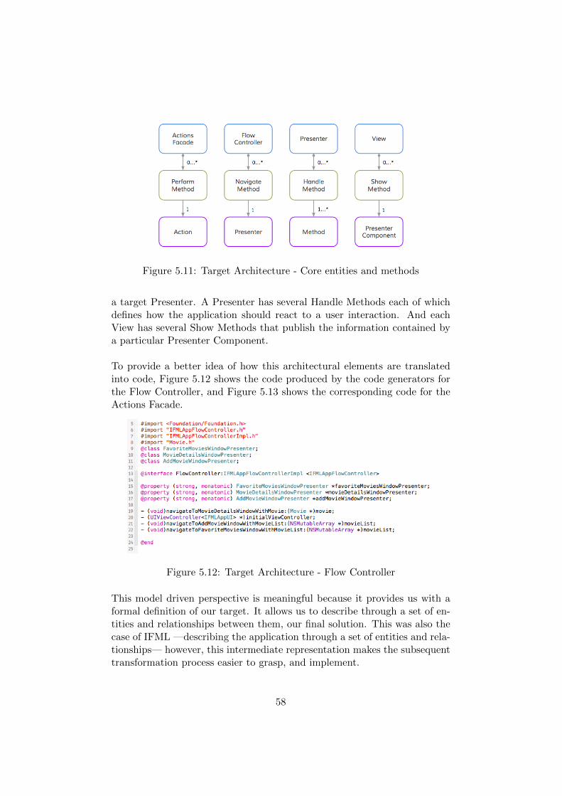
Figure 5.11: Target Architecture - Core entities and methods
a target Presenter. A Presenter has several Handle Methods each of whichdefines how the application should react to a user interaction. And eachView has several Show Methods that publish the information contained bya particular Presenter Component.
To provide a better idea of how this architectural elements are translatedinto code, Figure 5.12 shows the code produced by the code generators forthe Flow Controller, and Figure 5.13 shows the corresponding code for theActions Facade.
Figure 5.12: Target Architecture - Flow Controller
This model driven perspective is meaningful because it provides us with aformal definition of our target. It allows us to describe through a set of en-tities and relationships between them, our final solution. This was also thecase of IFML —describing the application through a set of entities and rela-tionships— however, this intermediate representation makes the subsequenttransformation process easier to grasp, and implement.
58
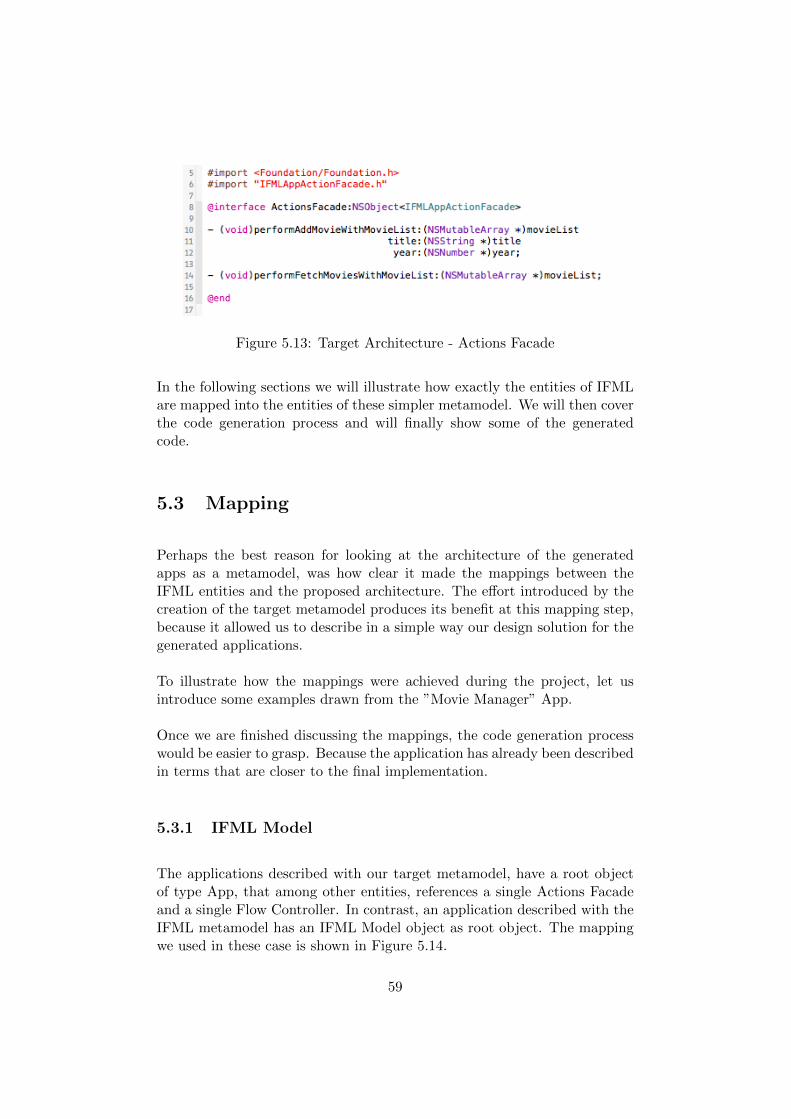
Figure 5.13: Target Architecture - Actions Facade
In the following sections we will illustrate how exactly the entities of IFMLare mapped into the entities of these simpler metamodel. We will then coverthe code generation process and will finally show some of the generatedcode.
5.3 Mapping
Perhaps the best reason for looking at the architecture of the generatedapps as a metamodel, was how clear it made the mappings between theIFML entities and the proposed architecture. The effort introduced by thecreation of the target metamodel produces its benefit at this mapping step,because it allowed us to describe in a simple way our design solution for thegenerated applications.
To illustrate how the mappings were achieved during the project, let usintroduce some examples drawn from the ”Movie Manager” App.
Once we are finished discussing the mappings, the code generation processwould be easier to grasp. Because the application has already been describedin terms that are closer to the final implementation.
5.3.1 IFML Model
The applications described with our target metamodel, have a root objectof type App, that among other entities, references a single Actions Facadeand a single Flow Controller. In contrast, an application described with theIFML metamodel has an IFML Model object as root object. The mappingwe used in these case is shown in Figure 5.14.
59
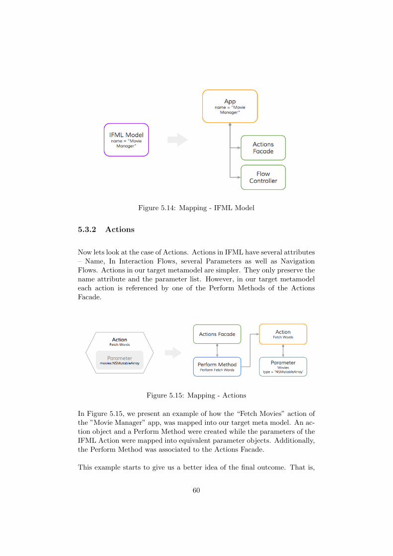
Figure 5.14: Mapping - IFML Model
5.3.2 Actions
Now lets look at the case of Actions. Actions in IFML have several attributes– Name, In Interaction Flows, several Parameters as well as NavigationFlows. Actions in our target metamodel are simpler. They only preserve thename attribute and the parameter list. However, in our target metamodeleach action is referenced by one of the Perform Methods of the ActionsFacade.
Figure 5.15: Mapping - Actions
In Figure 5.15, we present an example of how the “Fetch Movies” action ofthe ”Movie Manager” app, was mapped into our target meta model. An ac-tion object and a Perform Method were created while the parameters of theIFML Action were mapped into equivalent parameter objects. Additionally,the Perform Method was associated to the Actions Facade.
This example starts to give us a better idea of the final outcome. That is,
60
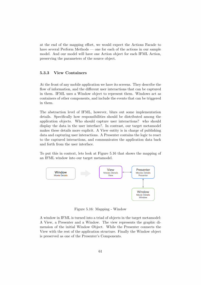
at the end of the mapping effort, we would expect the Actions Facade tohave several Perform Methods — one for each of the actions in our samplemodel. And our model will have one Action object for each IFML Action,preserving the parameters of the source object.
5.3.3 View Containers
At the front of any mobile application we have its screens. They describe theflow of information, and the different user interactions that can be capturedin them. IFML uses a Window object to represent them. Windows act ascontainers of other components, and include the events that can be triggeredin them.
The abstraction level of IFML, however, blurs out some implementationdetails. Specifically how responsibilities should be distributed among theapplication objects. Who should capture user interactions? who shoulddisplay the data in the user interface?. In contrast, our target metamodelmakes these details more explicit. A View entity is in charge of publishingdata and capturing user interactions. A Presenter contains the logic to reactto the captured interactions, and communicates the application data backand forth from the user interface.
To put this in context, lets look at Figure 5.16 that shows the mapping ofan IFML window into our target metamodel.
Figure 5.16: Mapping - Window
A window in IFML is turned into a triad of objects in the target metamodel:A View, a Presenter and a Window. The view represents the graphic di-mension of the initial Window Object. While the Presenter connects theView with the rest of the application structure. Finally the Window objectis preserved as one of the Presenter’s Components.
61
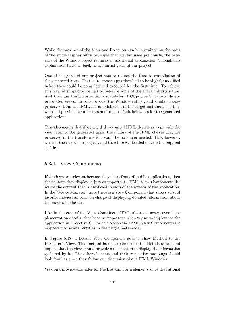
While the presence of the View and Presenter can be sustained on the basisof the single responsibility principle that we discussed previously, the pres-ence of the Window object requires an additional explanation. Though thisexplanation takes us back to the initial goals of our project.
One of the goals of our project was to reduce the time to compilation ofthe generated apps. That is, to create apps that had to be slightly modifiedbefore they could be compiled and executed for the first time. To achievethis level of simplicity we had to preserve some of the IFML infrastructure.And then use the introspection capabilities of Objective-C, to provide ap-propriated views. In other words, the Window entity , and similar classespreserved from the IFML metamodel, exist in the target metamodel so thatwe could provide default views and other default behaviors for the generatedapplications.
This also means that if we decided to compel IFML designers to provide theview layer of the generated apps, then many of the IFML classes that arepreserved in the transformation would be no longer needed. This, however,was not the case of our project, and therefore we decided to keep the requiredentities.
5.3.4 View Components
If windows are relevant because they sit at front of mobile applications, thenthe content they display is just as important. IFML View Components de-scribe the content that is displayed in each of the screens of the application.In the ”Movie Manager” app, there is a View Component that shows a list offavorite movies; an other in charge of displaying detailed information aboutthe movies in the list.
Like in the case of the View Containers, IFML abstracts away several im-plementation details, that become important when trying to implement theapplication in Objective-C. For this reason the IFML View Components aremapped into several entities in the target metamodel.
In Figure 5.18, a Details View Component adds a Show Method to thePresenter’s View. This method holds a reference to the Details object andimplies that the view should provide a mechanism to display the informationgathered by it. The other elements and their respective mappings shouldlook familiar since they follow our discussion about IFML Windows.
We don’t provide examples for the List and Form elements since the rational
62
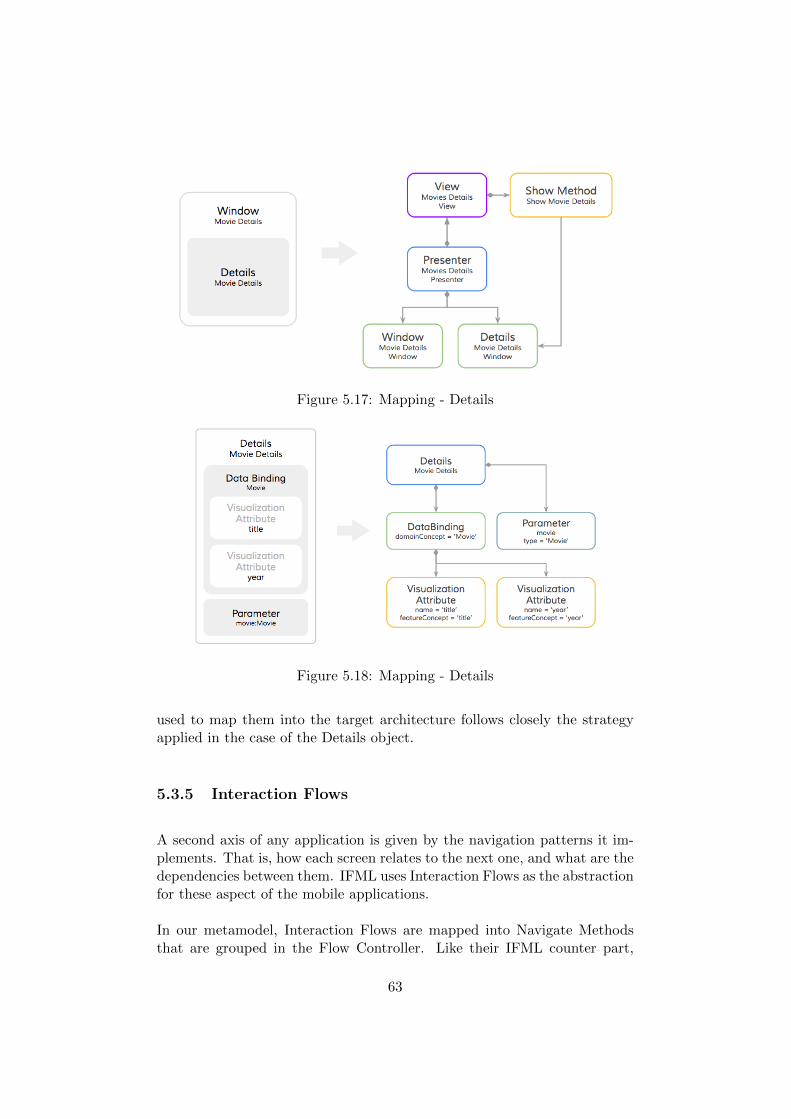
Figure 5.17: Mapping - Details
Figure 5.18: Mapping - Details
used to map them into the target architecture follows closely the strategyapplied in the case of the Details object.
5.3.5 Interaction Flows
A second axis of any application is given by the navigation patterns it im-plements. That is, how each screen relates to the next one, and what are thedependencies between them. IFML uses Interaction Flows as the abstractionfor these aspect of the mobile applications.
In our metamodel, Interaction Flows are mapped into Navigate Methodsthat are grouped in the Flow Controller. Like their IFML counter part,
63
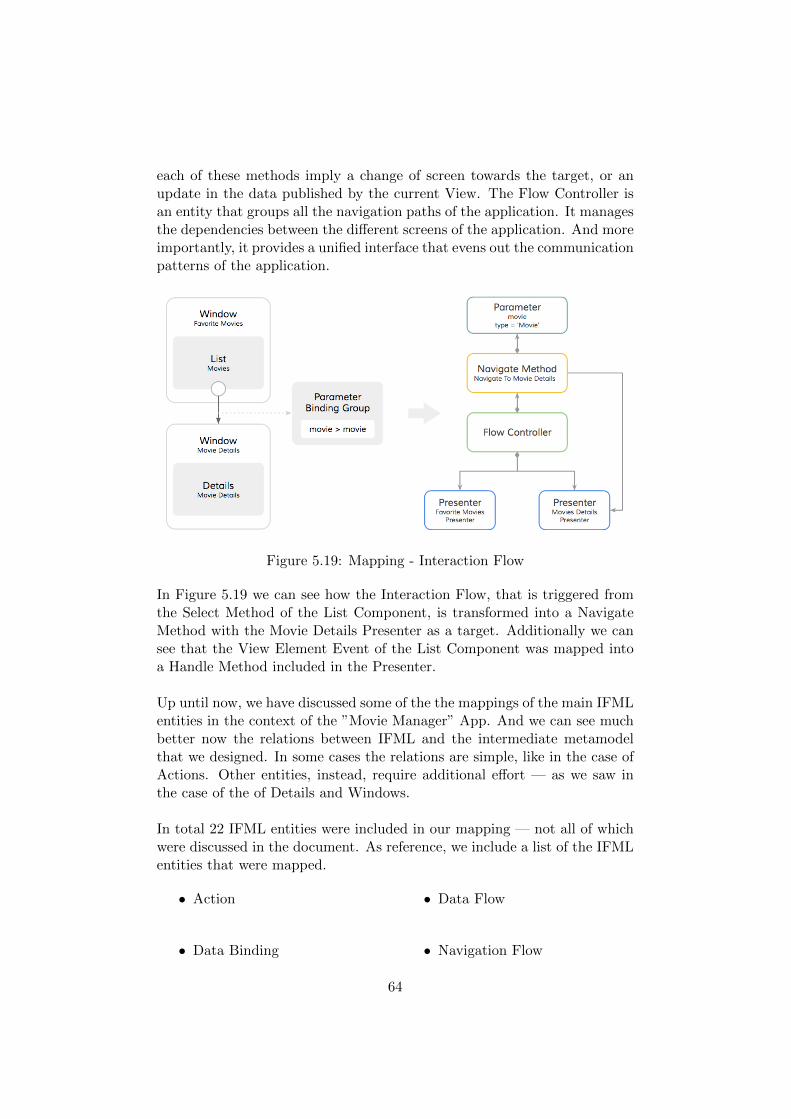
each of these methods imply a change of screen towards the target, or anupdate in the data published by the current View. The Flow Controller isan entity that groups all the navigation paths of the application. It managesthe dependencies between the different screens of the application. And moreimportantly, it provides a unified interface that evens out the communicationpatterns of the application.
Figure 5.19: Mapping - Interaction Flow
In Figure 5.19 we can see how the Interaction Flow, that is triggered fromthe Select Method of the List Component, is transformed into a NavigateMethod with the Movie Details Presenter as a target. Additionally we cansee that the View Element Event of the List Component was mapped intoa Handle Method included in the Presenter.
Up until now, we have discussed some of the the mappings of the main IFMLentities in the context of the ”Movie Manager” App. And we can see muchbetter now the relations between IFML and the intermediate metamodelthat we designed. In some cases the relations are simple, like in the case ofActions. Other entities, instead, require additional effort — as we saw inthe case of the of Details and Windows.
In total 22 IFML entities were included in our mapping — not all of whichwere discussed in the document. As reference, we include a list of the IFMLentities that were mapped.
• Action
• Data Binding
• Data Flow
• Navigation Flow
64
• Parameter
• Parameter Binding
• Parameter Binding Group
• UML Structural Feature
• UML Behavioral Feature
• UML Domain Concept
• Visualization Attribute
• Details
• Form
• List
• Menu
• OnLoadEvent
• OnSelectEvent
• OnSubmitEvent
• Selection Field
• Simple Field
• Slot
• Window
5.4 Static Library
Before developing the code generators we analyzed the code of the prototypeapp in order to understand how much code had to be dynamically generated.We started by filtering out the pieces of code that were model dependent— those that were deduced from the elements in the IFML model –, fromthe sections that would remain the same across the generated applications– or model independent. We then took the model independent sections, andpacked them into a static library. As for the model dependent pieces, wesingled them out as the ones that would have to be dynamically generated.
We called the Static Library, the IFML Kit. And we distributed it as a”private” cocoapod1.
The classes in the library helped us reduce the code that had to be dynam-ically generated, and provided the proper vessel for the default views of theapplications. As shown in Figure 5.20, the library was divided into threemain packages, each of which is discussed in the following sections.
5.4.1 Simplified Meta-model Package
One of our goals during this part of the project was to provide a set of defaultviews for the generated code. In this way, software designers could compile
1 available at https://github.com/acerosalazar/ifml-ifmlkit.git
65
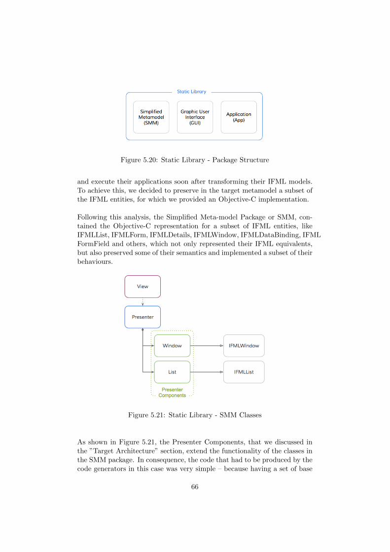
Figure 5.20: Static Library - Package Structure
and execute their applications soon after transforming their IFML models.To achieve this, we decided to preserve in the target metamodel a subset ofthe IFML entities, for which we provided an Objective-C implementation.
Following this analysis, the Simplified Meta-model Package or SMM, con-tained the Objective-C representation for a subset of IFML entities, likeIFMLList, IFMLForm, IFMLDetails, IFMLWindow, IFMLDataBinding, IFMLFormField and others, which not only represented their IFML equivalents,but also preserved some of their semantics and implemented a subset of theirbehaviours.
Figure 5.21: Static Library - SMM Classes
As shown in Figure 5.21, the Presenter Components, that we discussed inthe ”Target Architecture” section, extend the functionality of the classes inthe SMM package. In consequence, the code that had to be produced by thecode generators in this case was very simple – because having a set of base
66
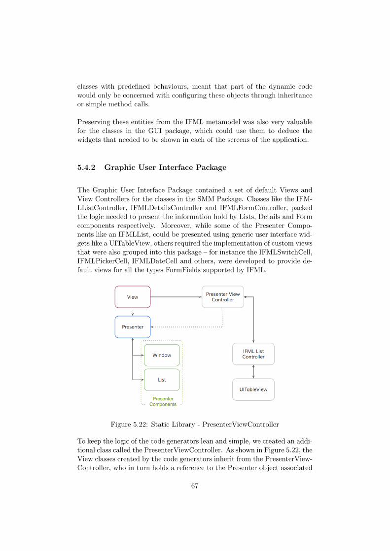
classes with predefined behaviours, meant that part of the dynamic codewould only be concerned with configuring these objects through inheritanceor simple method calls.
Preserving these entities from the IFML metamodel was also very valuablefor the classes in the GUI package, which could use them to deduce thewidgets that needed to be shown in each of the screens of the application.
5.4.2 Graphic User Interface Package
The Graphic User Interface Package contained a set of default Views andView Controllers for the classes in the SMM Package. Classes like the IFM-LListController, IFMLDetailsController and IFMLFormController, packedthe logic needed to present the information hold by Lists, Details and Formcomponents respectively. Moreover, while some of the Presenter Compo-nents like an IFMLList, could be presented using generic user interface wid-gets like a UITableView, others required the implementation of custom viewsthat were also grouped into this package – for instance the IFMLSwitchCell,IFMLPickerCell, IFMLDateCell and others, were developed to provide de-fault views for all the types FormFields supported by IFML.
Figure 5.22: Static Library - PresenterViewController
To keep the logic of the code generators lean and simple, we created an addi-tional class called the PresenterViewController. As shown in Figure 5.22, theView classes created by the code generators inherit from the PresenterView-Controller, who in turn holds a reference to the Presenter object associated
67
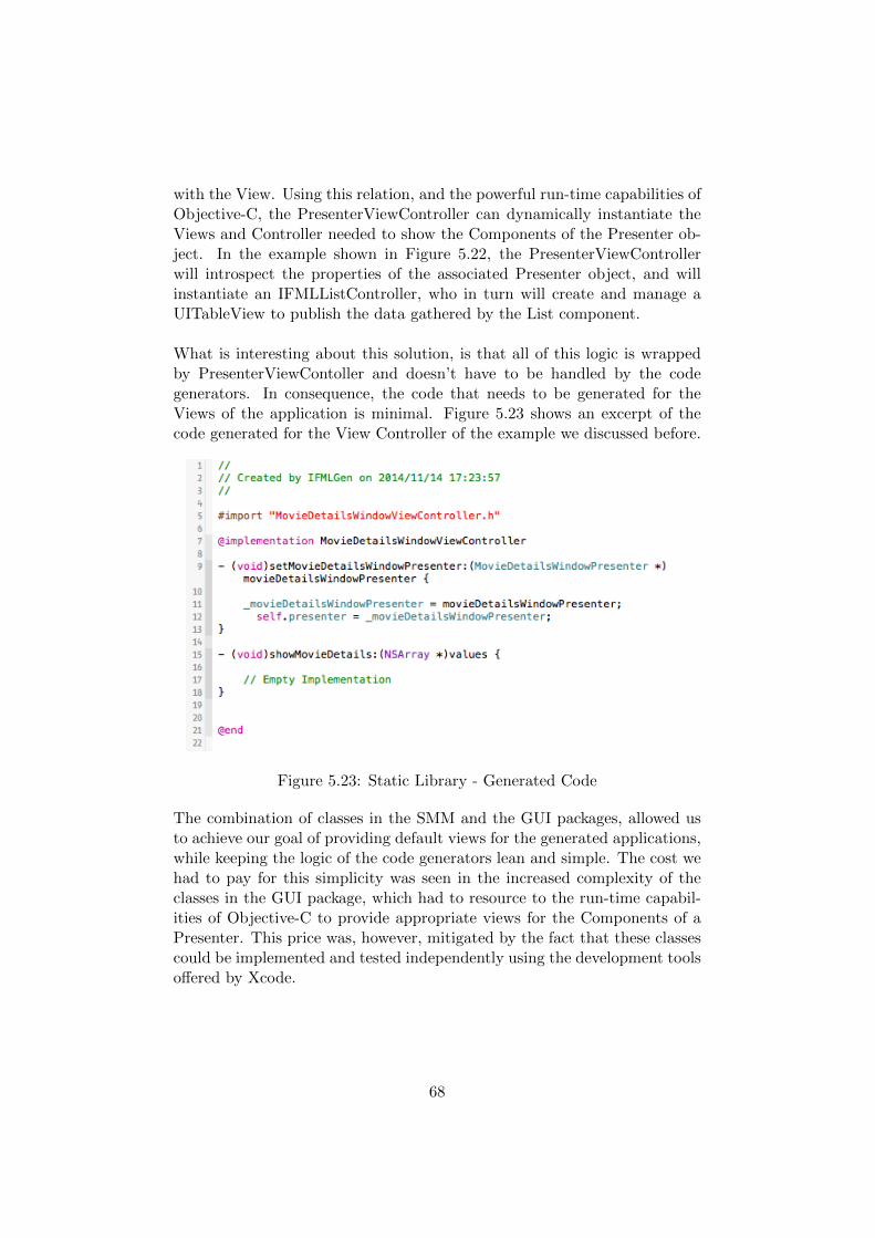
with the View. Using this relation, and the powerful run-time capabilities ofObjective-C, the PresenterViewController can dynamically instantiate theViews and Controller needed to show the Components of the Presenter ob-ject. In the example shown in Figure 5.22, the PresenterViewControllerwill introspect the properties of the associated Presenter object, and willinstantiate an IFMLListController, who in turn will create and manage aUITableView to publish the data gathered by the List component.
What is interesting about this solution, is that all of this logic is wrappedby PresenterViewContoller and doesn’t have to be handled by the codegenerators. In consequence, the code that needs to be generated for theViews of the application is minimal. Figure 5.23 shows an excerpt of thecode generated for the View Controller of the example we discussed before.
Figure 5.23: Static Library - Generated Code
The combination of classes in the SMM and the GUI packages, allowed usto achieve our goal of providing default views for the generated applications,while keeping the logic of the code generators lean and simple. The cost wehad to pay for this simplicity was seen in the increased complexity of theclasses in the GUI package, which had to resource to the run-time capabil-ities of Objective-C to provide appropriate views for the Components of aPresenter. This price was, however, mitigated by the fact that these classescould be implemented and tested independently using the development toolsoffered by Xcode.
68
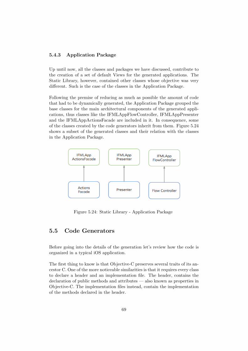
5.4.3 Application Package
Up until now, all the classes and packages we have discussed, contribute tothe creation of a set of default Views for the generated applications. TheStatic Library, however, contained other classes whose objective was verydifferent. Such is the case of the classes in the Application Package.
Following the premise of reducing as much as possible the amount of codethat had to be dynamically generated, the Application Package grouped thebase classes for the main architectural components of the generated appli-cations, thus classes like the IFMLAppFlowController, IFMLAppPresenterand the IFMLAppActionsFacade are included in it. In consequence, someof the classes created by the code generators inherit from them. Figure 5.24shows a subset of the generated classes and their relation with the classesin the Application Package.
Figure 5.24: Static Library - Application Package
5.5 Code Generators
Before going into the details of the generation let’s review how the code isorganized in a typical iOS application.
The first thing to know is that Objective-C preserves several traits of its an-cestor C. One of the more noticeable similarities is that it requires every classto declare a header and an implementation file. The header, contains thedeclaration of public methods and attributes — also known as properties inObjective-C. The implementation files instead, contain the implementationof the methods declared in the header.
69
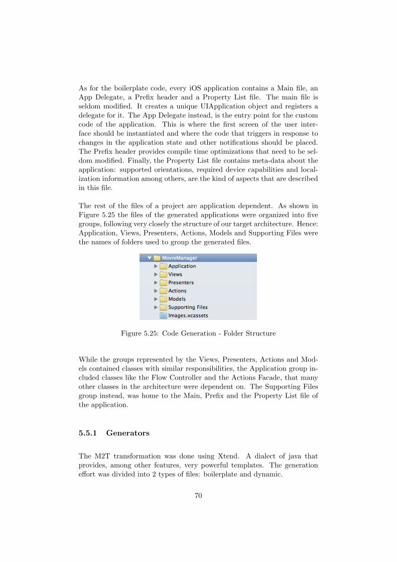
As for the boilerplate code, every iOS application contains a Main file, anApp Delegate, a Prefix header and a Property List file. The main file isseldom modified. It creates a unique UIApplication object and registers adelegate for it. The App Delegate instead, is the entry point for the customcode of the application. This is where the first screen of the user inter-face should be instantiated and where the code that triggers in response tochanges in the application state and other notifications should be placed.The Prefix header provides compile time optimizations that need to be sel-dom modified. Finally, the Property List file contains meta-data about theapplication: supported orientations, required device capabilities and local-ization information among others, are the kind of aspects that are describedin this file.
The rest of the files of a project are application dependent. As shown inFigure 5.25 the files of the generated applications were organized into fivegroups, following very closely the structure of our target architecture. Hence:Application, Views, Presenters, Actions, Models and Supporting Files werethe names of folders used to group the generated files.
Figure 5.25: Code Generation - Folder Structure
While the groups represented by the Views, Presenters, Actions and Mod-els contained classes with similar responsibilities, the Application group in-cluded classes like the Flow Controller and the Actions Facade, that manyother classes in the architecture were dependent on. The Supporting Filesgroup instead, was home to the Main, Prefix and the Property List file ofthe application.
5.5.1 Generators
The M2T transformation was done using Xtend. A dialect of java thatprovides, among other features, very powerful templates. The generationeffort was divided into 2 types of files: boilerplate and dynamic.
70
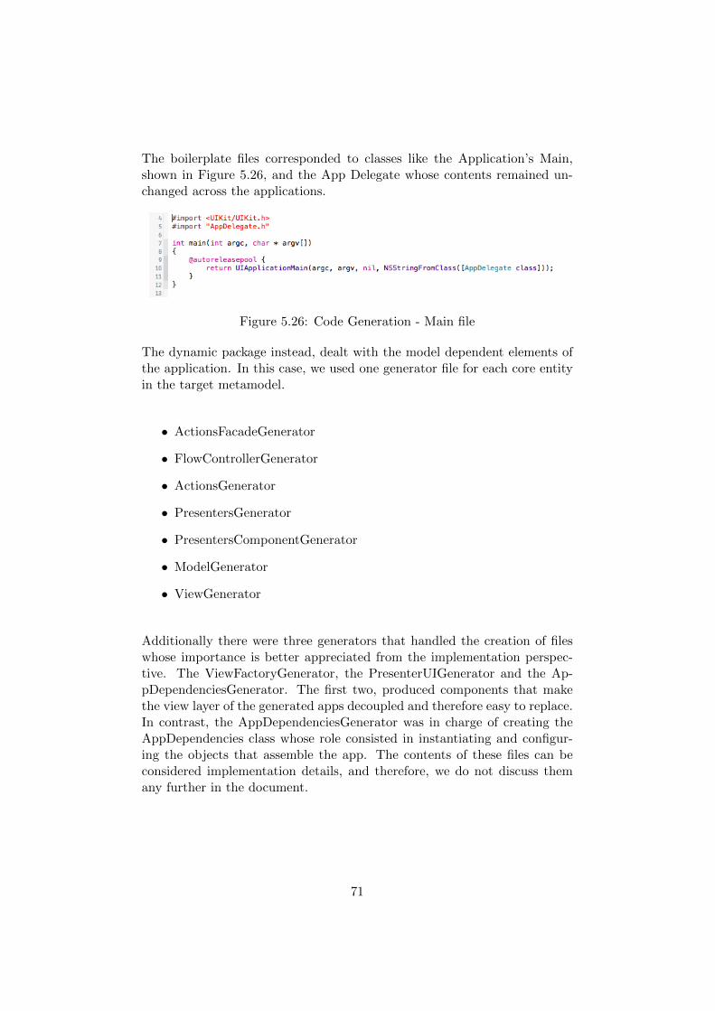
The boilerplate files corresponded to classes like the Application’s Main,shown in Figure 5.26, and the App Delegate whose contents remained un-changed across the applications.
Figure 5.26: Code Generation - Main file
The dynamic package instead, dealt with the model dependent elements ofthe application. In this case, we used one generator file for each core entityin the target metamodel.
• ActionsFacadeGenerator
• FlowControllerGenerator
• ActionsGenerator
• PresentersGenerator
• PresentersComponentGenerator
• ModelGenerator
• ViewGenerator
Additionally there were three generators that handled the creation of fileswhose importance is better appreciated from the implementation perspec-tive. The ViewFactoryGenerator, the PresenterUIGenerator and the Ap-pDependenciesGenerator. The first two, produced components that makethe view layer of the generated apps decoupled and therefore easy to replace.In contrast, the AppDependenciesGenerator was in charge of creating theAppDependencies class whose role consisted in instantiating and configur-ing the objects that assemble the app. The contents of these files can beconsidered implementation details, and therefore, we do not discuss themany further in the document.
71
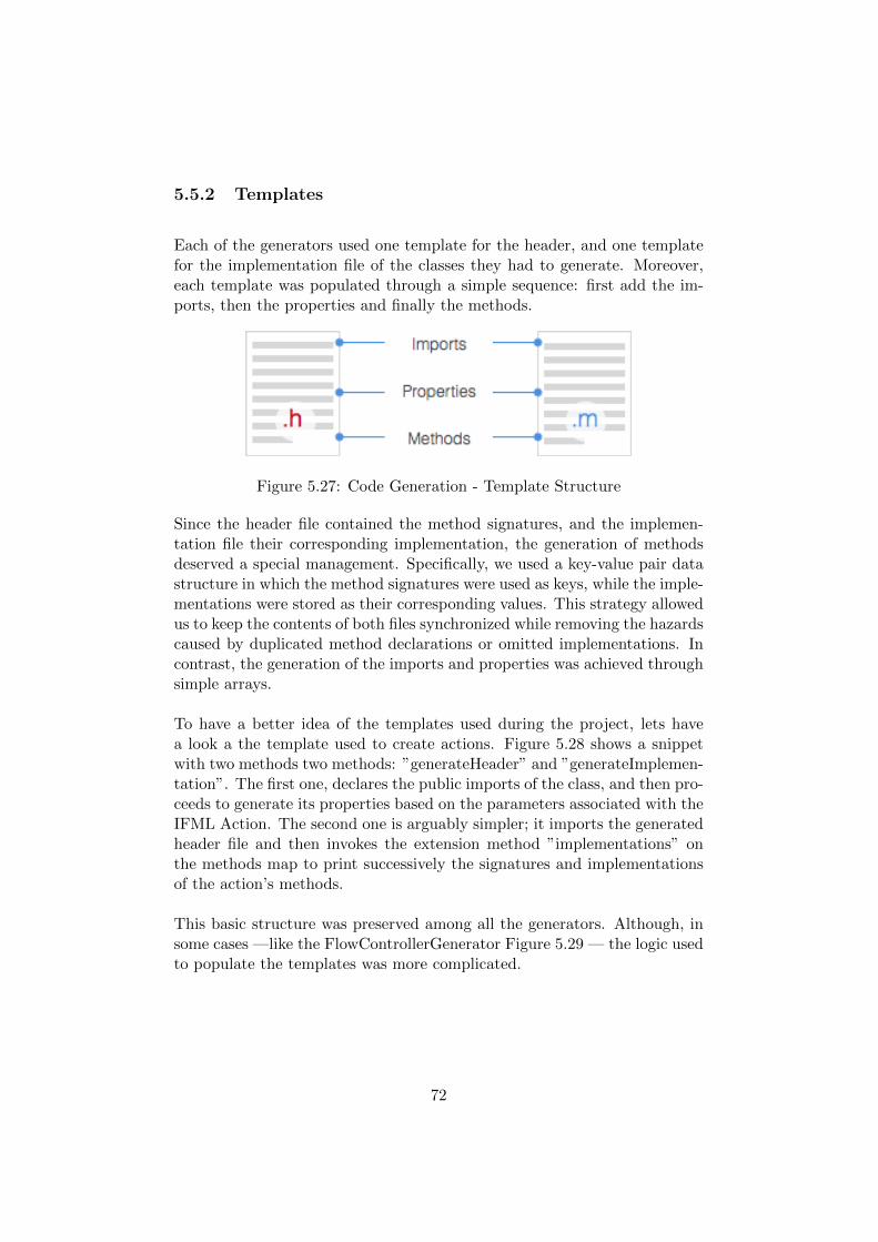
5.5.2 Templates
Each of the generators used one template for the header, and one templatefor the implementation file of the classes they had to generate. Moreover,each template was populated through a simple sequence: first add the im-ports, then the properties and finally the methods.
Figure 5.27: Code Generation - Template Structure
Since the header file contained the method signatures, and the implemen-tation file their corresponding implementation, the generation of methodsdeserved a special management. Specifically, we used a key-value pair datastructure in which the method signatures were used as keys, while the imple-mentations were stored as their corresponding values. This strategy allowedus to keep the contents of both files synchronized while removing the hazardscaused by duplicated method declarations or omitted implementations. Incontrast, the generation of the imports and properties was achieved throughsimple arrays.
To have a better idea of the templates used during the project, lets havea look a the template used to create actions. Figure 5.28 shows a snippetwith two methods two methods: ”generateHeader” and ”generateImplemen-tation”. The first one, declares the public imports of the class, and then pro-ceeds to generate its properties based on the parameters associated with theIFML Action. The second one is arguably simpler; it imports the generatedheader file and then invokes the extension method ”implementations” onthe methods map to print successively the signatures and implementationsof the action’s methods.
This basic structure was preserved among all the generators. Although, insome cases —like the FlowControllerGenerator Figure 5.29 — the logic usedto populate the templates was more complicated.
72
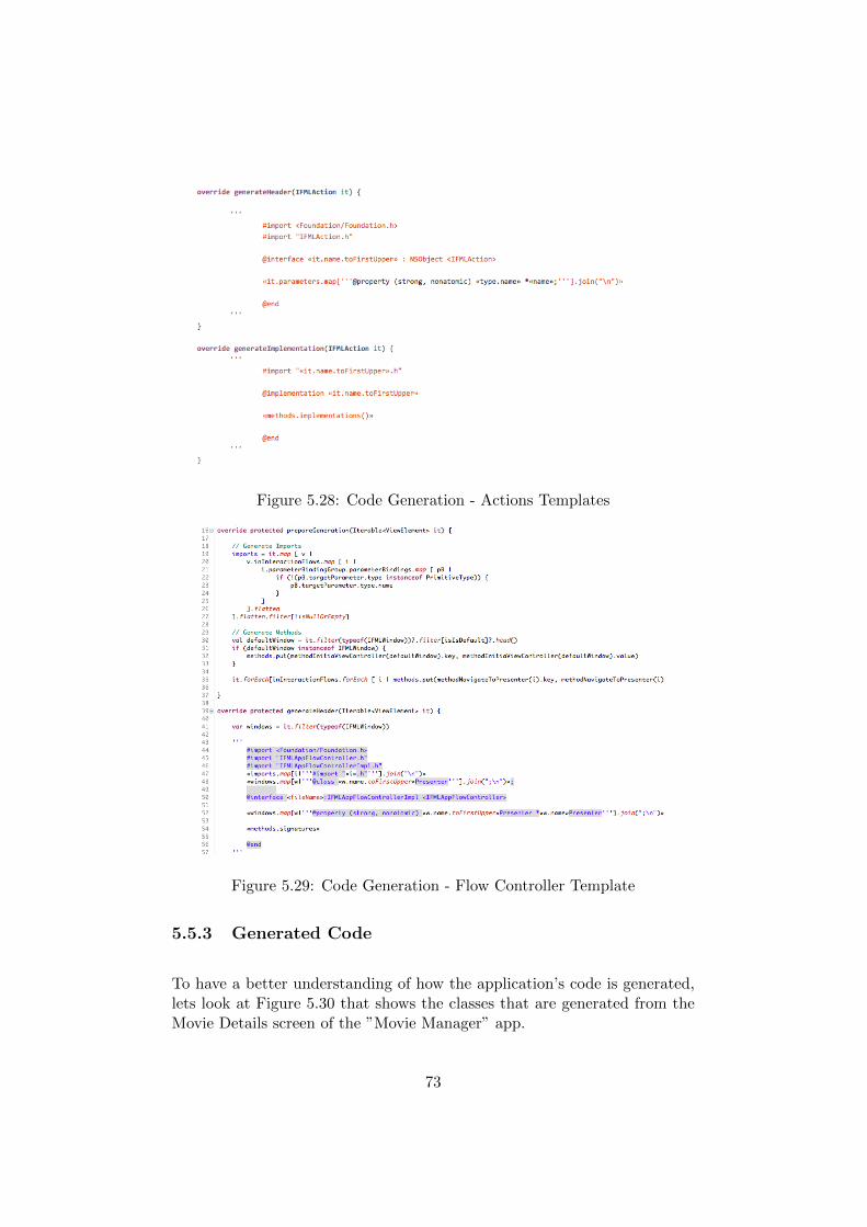
Figure 5.28: Code Generation - Actions Templates
Figure 5.29: Code Generation - Flow Controller Template
5.5.3 Generated Code
To have a better understanding of how the application’s code is generated,lets look at Figure 5.30 that shows the classes that are generated from theMovie Details screen of the ”Movie Manager” app.
73
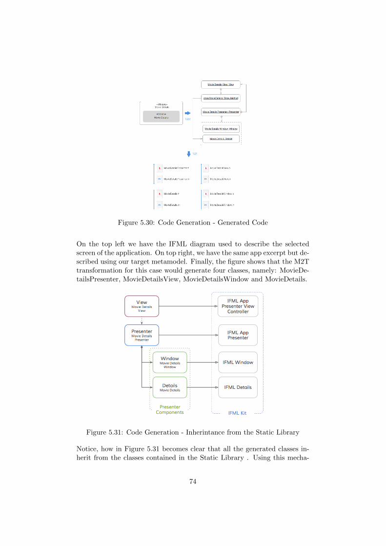
Figure 5.30: Code Generation - Generated Code
On the top left we have the IFML diagram used to describe the selectedscreen of the application. On top right, we have the same app excerpt but de-scribed using our target metamodel. Finally, the figure shows that the M2Ttransformation for this case would generate four classes, namely: MovieDe-tailsPresenter, MovieDetailsView, MovieDetailsWindow and MovieDetails.
Figure 5.31: Code Generation - Inherintance from the Static Library
Notice, how in Figure 5.31 becomes clear that all the generated classes in-herit from the classes contained in the Static Library . Using this mecha-
74
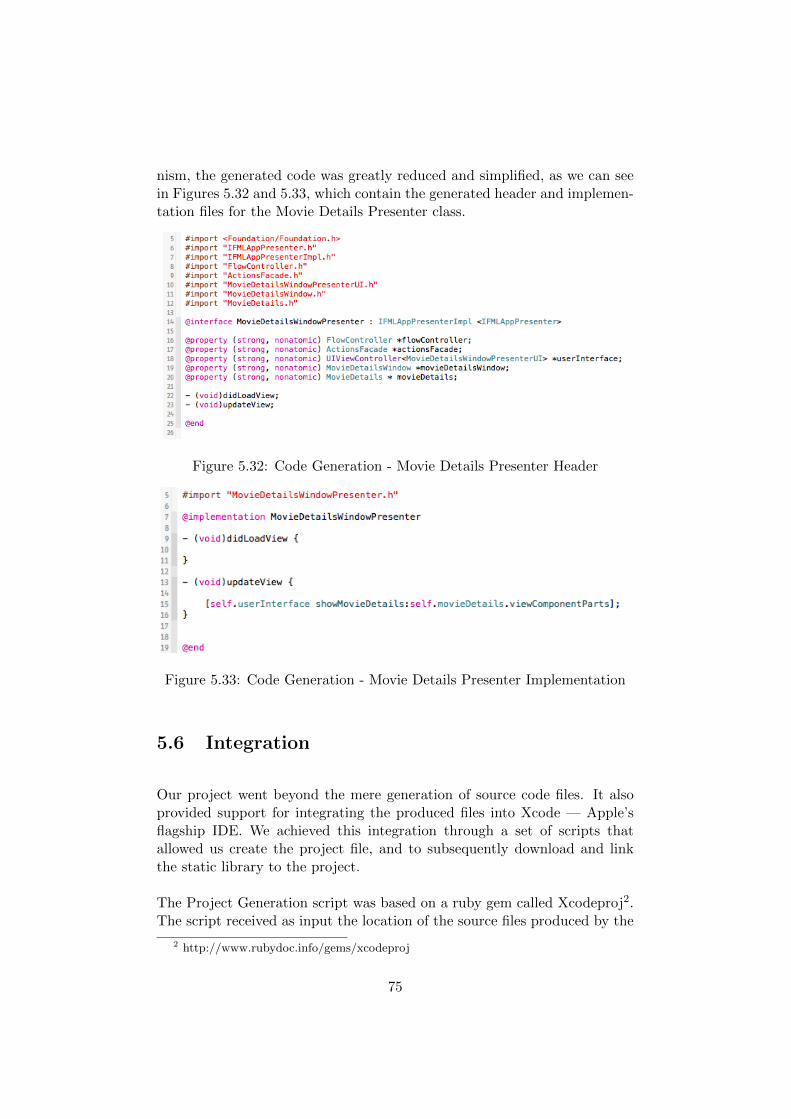
nism, the generated code was greatly reduced and simplified, as we can seein Figures 5.32 and 5.33, which contain the generated header and implemen-tation files for the Movie Details Presenter class.
Figure 5.32: Code Generation - Movie Details Presenter Header
Figure 5.33: Code Generation - Movie Details Presenter Implementation
5.6 Integration
Our project went beyond the mere generation of source code files. It alsoprovided support for integrating the produced files into Xcode — Apple’sflagship IDE. We achieved this integration through a set of scripts thatallowed us create the project file, and to subsequently download and linkthe static library to the project.
The Project Generation script was based on a ruby gem called Xcodeproj2.The script received as input the location of the source files produced by the
2 http://www.rubydoc.info/gems/xcodeproj
75
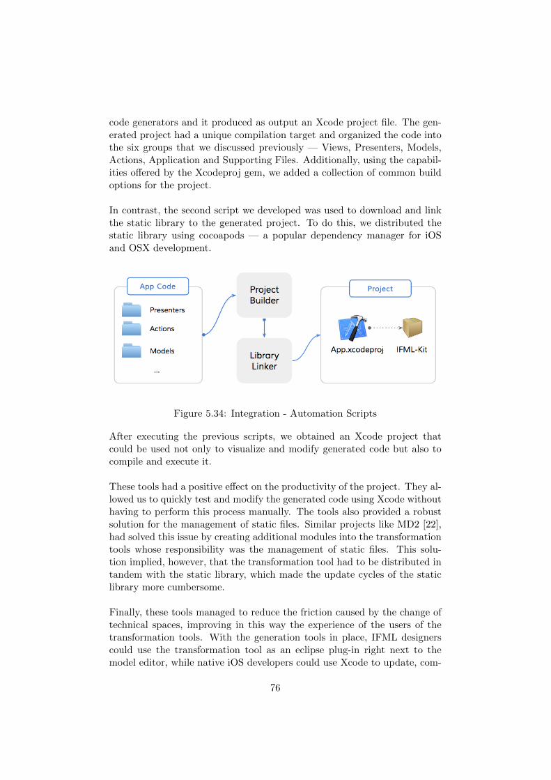
code generators and it produced as output an Xcode project file. The gen-erated project had a unique compilation target and organized the code intothe six groups that we discussed previously — Views, Presenters, Models,Actions, Application and Supporting Files. Additionally, using the capabil-ities offered by the Xcodeproj gem, we added a collection of common buildoptions for the project.
In contrast, the second script we developed was used to download and linkthe static library to the generated project. To do this, we distributed thestatic library using cocoapods — a popular dependency manager for iOSand OSX development.
Figure 5.34: Integration - Automation Scripts
After executing the previous scripts, we obtained an Xcode project thatcould be used not only to visualize and modify generated code but also tocompile and execute it.
These tools had a positive effect on the productivity of the project. They al-lowed us to quickly test and modify the generated code using Xcode withouthaving to perform this process manually. The tools also provided a robustsolution for the management of static files. Similar projects like MD2 [22],had solved this issue by creating additional modules into the transformationtools whose responsibility was the management of static files. This solu-tion implied, however, that the transformation tool had to be distributed intandem with the static library, which made the update cycles of the staticlibrary more cumbersome.
Finally, these tools managed to reduce the friction caused by the change oftechnical spaces, improving in this way the experience of the users of thetransformation tools. With the generation tools in place, IFML designerscould use the transformation tool as an eclipse plug-in right next to themodel editor, while native iOS developers could use Xcode to update, com-
76
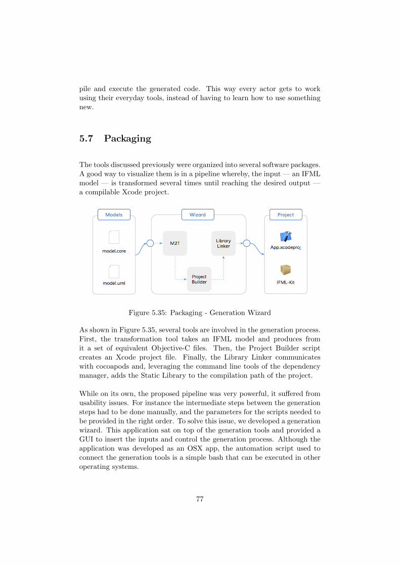
pile and execute the generated code. This way every actor gets to workusing their everyday tools, instead of having to learn how to use somethingnew.
5.7 Packaging
The tools discussed previously were organized into several software packages.A good way to visualize them is in a pipeline whereby, the input — an IFMLmodel — is transformed several times until reaching the desired output —a compilable Xcode project.
Figure 5.35: Packaging - Generation Wizard
As shown in Figure 5.35, several tools are involved in the generation process.First, the transformation tool takes an IFML model and produces fromit a set of equivalent Objective-C files. Then, the Project Builder scriptcreates an Xcode project file. Finally, the Library Linker communicateswith cocoapods and, leveraging the command line tools of the dependencymanager, adds the Static Library to the compilation path of the project.
While on its own, the proposed pipeline was very powerful, it suffered fromusability issues. For instance the intermediate steps between the generationsteps had to be done manually, and the parameters for the scripts needed tobe provided in the right order. To solve this issue, we developed a generationwizard. This application sat on top of the generation tools and provided aGUI to insert the inputs and control the generation process. Although theapplication was developed as an OSX app, the automation script used toconnect the generation tools is a simple bash that can be executed in otheroperating systems.
77

In summary, the output of the project was packaged into six different tools,from which the the Code Generator, the Static Library and the ProjectBuilder work as standalone apps. In contrast, the Library Linker and theGeneration Wizard are dependent on the previous three and were added asa way of making the generation process more convenient. The links to therepositories that contain the source code of all these tools can be found inthis site: http://acerosalazar.github.io/ifml-gtk/.
78
Chapter 6
Conclusion
6.1 Results
At the end of the project we managed to reach our objectives. Specifically,to enhance the portability of IFML by developing a code generator for iOS,and to broaden the modeling capabilities of the language, by adding a setof extensions to its metamodel.
In the first case, we developed a toolset composed of a Model to Text trans-formation tool, a Project Builder and a Library Linker scripts. Using thesetools, we could produce a compilable Xcode project, starting with the IFMLand UML models of an application. To make things even simpler, we pro-vided a graphic wizard that made the transformation process a matter of acouple of clicks.
As for the language extensions, we proposed 90 new entities grouped intothree different packages. The General Extensions Package, which is com-posed of entities whose scope goes beyond mobile environments — like inthe case of the Image Attribute and the Map View. The Mobile ExtensionsPackage, whose classes are meant to broaden the types of user interactionsthat can be modeled with IFML – Pan, Pinch, Swipe, Tap, Touch andothers —, as well as the type of events that can be captured using thesensors included in modern mobile devices – Location Events, OrientationEvents, Accelerometer Events, Gyroscope Events, among others. Finallythe Private Extensions Package, was home to the entities that extended theContext classes, which, as of this writing, is not allowed outside a privatescope by the current version of the IFML standard [21].
79
In addition to these results, we believe that the methodology used to conductthe research was an important byproduct of the project. This is speciallyrelevant in the case of IFML, since there are several research teams workingin projects with similar goals, for whom this insight could be of great value.
There is, however, room for improvement.
6.2 Critical Analysis
The current version of the code generators supports a subset of 22 entitiesfrom the total amount of classes defined by the IFML standard [21]. Leavinguncovered important entities like the UML Behaviours, and a great portionof the Expressions hierarchy. Moreover, data persistence, which is an im-portant aspect in modern mobile applications, was narrowly addressed inour project and therefore deserves a deeper look.
As for the language extensions, the proposed entities need to be furtherdiscussed and evaluated, to understand their practical value. Then, a suit-able graphic syntax should be proposed, so that they could be added intothe IFML Model Editor. Allowing code generators to provide mappingsfor them, and software engineers to start using them in the models of theirapplications.
6.3 Future Work
Finally, to keep our project within the scope and time constraints, we hadto steer clear from some opportunities that should be, however, explored infuture efforts.
The first opportunity is provided by Swift – Apple’s new programming lan-guage. Its simpler syntax, and stronger type system may lead to severalimprovements in the code generators, and specially to simpler templatesand a more straightforward generation logic.
The second opportunity lies in the possibilities offered by the Model Drivenworld. In particular, we consider that an intermediate metamodel thatbrings the concepts of IFML closer to a traditional MVC architecture, shouldbe designed. This metamodel would formalize the architecture of the gener-ated applications, and since it would be defined at a platform independent
80

level, existing code generators for IFML could use it as the starting pointfor the model to text transformation process. This strategy would have pos-itive implications in several fronts. On one hand, cross-platform developerswill have to be familiar with a unique architecture, that will be preservedacross the code generated for the different platforms. On the other hand,the developers in charge of the code generators would be able to collaboratein the creation of more robust generation strategies. And finally, externalobservers and other interested people, would be able to understand at ahigher level of abstraction, the way code generation is achieved in IFML.
Our final words, are dedicated to the IFML Model Editor.
During the first stages of our project we had access to an early version ofthe editor, which we used to visualize and modify the IFML model of ourprototype application. While this early version had some rough edges, thetool was very important in achieving our final results, and helped us in thecreation of well formed models that could be used by our code generators.We believe that, once finished, this tool will be of great value for softwaredesigners, and that the development team behind it should continue im-proving its features and broadening in its capabilities. A good place to startthis improvements, would be adding support for the introduction of privateextensions into the editor, which will allow for a more dynamic evolution ofthe modeling language.
81
Appendix A
General Extensions Package
Application Lifecycle Event
Abstract: NoGeneralization: Mobile System Event
Application Lifecycle Events model each of the notifications triggered byoperating system to inform applications about changes in their life-cycles.For instance, operating systems can inform an application when it has beenlaunched, or when it is about to be terminated. Similarly, an applicationcan receive updates on whether it is executing in the foreground or in thebackground.
Expanded Selection Field
Abstract: NoGeneralization: Selection Field
Expanded Selection Fields can be used to indicate that all the options offeredby a Selection Field should be displayed to the user at once rather thanone at the time. In contrast with regular Selection Fields, code generatorscould map Expanded Selection Fields into more suitable and specific GUIcomponents like button groups instead of using more generic componentslike a combo-box.
Enumeration View Lifecycle Event Type
82
The values of this enumeration describe the notifications that are typicallyraised by the system after there has been an update on the state of a par-ticular view.
Literals
• View Did Appear: This type of event is triggered after a view has beenallocated memory and has been successfully rendered to the user [13].
• View Did Disappear: This event is triggered after a view has beenremoved from the screen, but not necessarily so from main memory[13].
• View Did Load: This event is triggered after a view has been allocatedmemory. This is the earliest point at which a view or its correspondingcontroller may execute additional initialization routines [13].
• View Will Appear: This event is triggered when a view is ready to berendered to the user. While the View Did Load event may be triggeredonly once (after a view and its corresponding controller have beenallocated memory), the View Will Appear event should be triggeredevery time the view is ready to be shown [13].
• View Will Disappear: This is event is triggered just before a view isremoved from the screen [13].
Enumeration Application Lifecycle Event Type
The values of this enumeration describe the notifications that are raised bythe system after there has been an update on the application state.
Literals
• App Did Launch: This event is raised right after the user launches theapplication [17].
• App Will Become Active: This event is triggered just before an ap-plication is switched to foreground mode and will become the activeapplication. In contrast with the background mode, applications inthe foreground can receive user interactions [17].
83
• App Did Become Active: This event is triggered right after an ap-plication has changed its state from inactive to active, and its beingexecuted in the foreground [17].
• App Will Hide: This event is triggered just before an application isminimized. Since mobile nor web applications are susceptible to thiskind of transitions, the usage of this event is restricted to Desktopapplications.
• App Did Hide: This event is triggered right after an application hasbeen minimized. Since mobile nor web applications are susceptible tothis kind of transitions, the usage of this event is restricted to Desktopapplications.
• App Will Unhide: This event is triggered right before an applicationis maximized. Since mobile nor web applications are susceptible tothis kind of transitions, the usage of this event is restricted to Desktopapplications.
• App Did Unhide: This event is triggered right after an application hasbeen maximized. Since mobile nor web applications are susceptible tothis kind of transitions, the usage of this event is restricted to Desktopapplications.
• App Will Resign Active: This event is raised just before an applicationtransitions form an active state to an inactive state. Such transitionhappens every time a user switches to another application [17].
• App Did Resign Active: This event is triggered right after a user hasjust switched focus to a different application[17].
• App Will Terminate: This events is triggered before an application isterminated and removed from main memory [17].
Image Attribute
Abstract: NoGeneralization: Visualization Attribute
Image Attributes allow IFML designers to explicitly indicate that a par-ticular attribute should be rendered as an image. In contrast with ImageAttributes, generic Visual Attributes would rely on the capabilities of thecode generators to infer the type of data that needs to be shown in theUI based on the associated Data Bindings, which in turn may not be soaccurate.
84
Map Annotation
Abstract: NoGeneralization: View Component
Map annotations describe points of interest in a map, and can naturally beincluded only within a Map View.
Constraints
• Map Annotations must have a Data Binding that provides them witha geographic coordinate that indicates the exact location of the mapwhere they need to be rendered. Optionally, the Data Binding couldalso include the additional information that should be shown to theuser in these points.
• They can only be added into Map Views.
Map Overlay
Abstract: NoGeneralization: View Component
Map Overlays represent poly lines, shapes and other graphical elements thatcan be shown on top of a map. IFML designers could use map overlays tomodel maps that convey information in a more convenient way – e.g usingpoly lines to describe routes or shapes to identify areas of interest for theuser.
Constraints
• Map Overlays require a Data Binding to provide them with the geo-graphical information and the description of the shape, if any, used torepresent them.
• They can only be added into Map Views.
Map View
Abstract: NoGeneralization: View Container
85
Map Views are off-the shelf interactive map visualizations that are frequentlyused in mobile, web and desktop applications. They can only contain MapAnnotations and Map Overlays which, in turn, are used to display points ofinterest and map related information in a meaningful way.
Constraints
• Map views can contain Map Annotation and Map Overlay componentsonly.
Modal Menu
Abstract: NoGeneralization: Menu
A Modal Menu represents a set of commands that can be dismissed. Similarto Menus, the commands available within a Modal Menu can be modeledby means of View Element Events, each of which may trigger a differentbusiness logic action.
Constraints
This type of View Containers cannot contain any View Elements.
Multi Line Field
Abstract: NoGeneralization: Simple Field
Multiline Fields allow IFML designers to indicate explicitly that a particularfield would be used for multiple line inputs. Such refinement will allow codegenerators to make better decisions and apply more meaningful mappings.In this way, Multiline Fields could be translated into more suitable GUIcomponents like text areas rather than into, the more general, text fields.
GL View
Abstract: NoGeneralization: View Component
GL Views model interface components that are rendered using advancedgraphics libraries like OpenGL or WebGL.
86
Range Selection Field
Abstract: NoGeneralization: Selection Field
Range Selection Fields are selection fields whose possible values lay withinare a range. Users can pick any continuous or discrete value as defined by astep. An IFML designer may use this view components to represent frequentGUI widgets like sliders and value steppers.
Attributes
• minValue [float] : the lower bound of the value range.
• maxValue [float] : the upper bound of the value range.
• stepValue [int]: the difference between two adjacent values. If thevalue of this attribute is NULL, the user will be allowed to select froma set of continuous values, thus without a defined step.
Constraints
• The minValue must be greater than the maxValue.
• The stepValue must be an integer greater than zero.
View Lifecycle Event
Abstract: NoGeneralization: Mobile System Event
View Lifecycle Events are triggered after a change in the state of a view’slifecycle. Such events can be used by IFML designers in order to modelresponsive and usable applications that react appropriately to such changes,and blend nicely with the resource management strategies put in place bythe operating systems.
Attributes
• Event Type [View Lifecycle Event Type]: The specific type of lifecycleevent triggered.
87
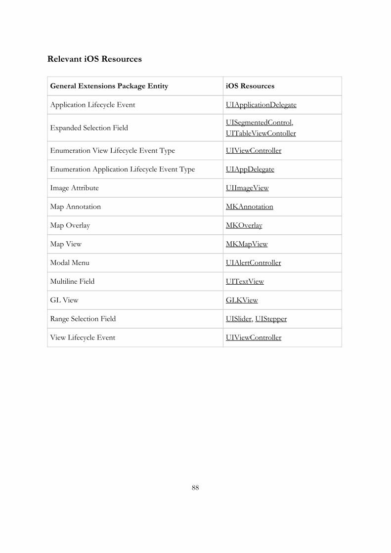
Relevant iOS Resources
General Extensions Package Entity iOS Resources
Application Lifecycle Event UIApplicationDelegate
Expanded Selection Field UISegmentedControl, UITableViewContoller
Enumeration View Lifecycle Event Type UIViewController
Enumeration Application Lifecycle Event Type UIAppDelegate
Image Attribute UIImageView
Map Annotation MKAnnotation
Map Overlay MKOverlay
Map View MKMapView
Modal Menu UIAlertController
Multiline Field UITextView
GL View GLKView
Range Selection Field UISlider, UIStepper
View Lifecycle Event UIViewController
88
Appendix B
Mobile Extensions Package
Accelerometer Event
Abstract: NoGeneralization: Sensor Event
This event will be fired every time there is a change on the device accelerationalong any of the spatial axis. This event may be used, for instance, inorder to allow users to interact with the application by physically movingtheir device. Since acceleration events can be considered as global events (meaning that they are perceived and affect equally all the elements of theapplication), they are categorized under the Catching Events entity. Becauseof it, they can be associated with Activation Expressions, Interaction FlowExpressions and Navigation Expression.
Ad Banner View
Abstract: NoGeneralization: Mobile View Component
The Ad Banner View Component is used to display banner advertisementsas supported in the SDKs of several mobile platforms [16] [20]. In generalIFML designers will simply include these components in their models inorder to allow Code Generators to produce the appropriate source code.Thus, without adding any events or navigation flows that affect them.
Battery Event
89
Abstract: NoGeneralization: Resource Event
Battery events will be raised when any changes related with the devicebattery level or battery status occur. Examples of such changes could be anupdate on the remaining battery power or a notification informing that thedevice has been plugged to the electrical outlet.
Bluetooth Event
Abstract: YesGeneralization: Resource Event
This kind of events will be raised upon device discovery and updates onconnection status as well as after receiving / completing requests relatedwith service publishing and consumption. Since mobile devices can behaveas bluetooth peripherals as well as a bluetooth centrals, further extensionsto provide a greater level of granularity are encouraged.
Enumeration Swipe Direction
Each of the directions in which a swipe gestures can be identified.
Literals
• Right: The user taps the screen and dragging his finger from left toright.
• Left: The user taps the screen dragging his finger from right to left.
• Up: The user taps the screen dragging his finger in direction down -up.
• Down: The user taps the screen dragging his finger in direction up -down.
Gyroscope Event
Abstract: NoGeneralization: Sensor Event
Gyroscope Events are raised every time there is a change on the device’srotation rate along any of the three spatial axis. IFML designers may use this
90
kind of events to allow users interact with their applications by physicallymoving and rotating their device.
Location Event
Abstract: NoGeneralization: Sensor Event
Location Events are triggered every time there is a change on the geographicposition of the user. IFML designers may use Location Events to modelapplications that offer navigation services, maps or that simply rely on userpositioning to deliver certain functionalities.
Long Press Event
Abstract: NoGeneralization: Touch Event
Long Press Events are raised when the user touches a particular view leavingits finger on the screen for certain amount of time. This type of events arefrequently used to display contextual menus, or activate alternative actions– e.g item sorting.
Attributes
• pressDuration [Float]: a value in seconds that specifies the period oftime that a user should press a view before a Long Press Event is fired.
• fingersCount [Int]: the number of simultaneous touches that the useris expected to perform so the event can be effectively captured.
Magnetometer Event
Abstract: NoGeneralization: Sensor Event
This type of events are triggered by changes on the orientation of the devicemeasured against the magnetic or the true north. This type of events aretypically used in apps that offer navigation services to identify the user’sheading direction.
Memory Event
91
Abstract: NoGeneralization: Resource Event
Memory events are usually warning notifications triggered by the system toinform mobile apps about the scarcity of memory resources and allow themto reduce their memory footprint if possible [17].
Motion Event
Abstract: NoGeneralization: Sensor Event
Motion events model changes on the rotation, orientation or linear velocityof the device. Motion events are a general classification for MagnetometerEvents, Accelerometer Events and Gyroscope Events.
Mobile Resource Event
Abstract: NoGeneralization: Mobile System Event
Mobile Resource Events are occurrences related with resources managed bythe system. This entity provides a general category for Memory Events,Bluetooth Events and Battery Events.
Mobile Sensor Event
Abstract: NoGeneralization: Mobile System Event
Mobile Sensor Events model notifications triggered by the sensors includedin modern mobile devices. This entity provides a general classification forLocation Events, Proximity Events, Motion Events, Magnetometer Events,Accelerometer Events, Gyroscope Events and Shake Events.
Mobile System Event
Abstract: YesGeneralization: System Event
A Mobile System Event is an Event produced by mobile operating systems,which is related with tasks and resources that they manage. This class pro-
92
vides a general classification for Mobile Sensor Events and Mobile ResourceEvents.
Mobile View Component
Abstract: YesGeneralization: View Component
Mobile View Components are View Components that are somewhat uniqueto mobile platforms. This abstract class provides a generalization for otherclasses like Web Views, Search Views and Ad Banner Views.
Mobile View Container
Abstract: YesGeneralization: View Container
A Mobile View Container is an abstract entity provides a generalizationfor container classes that are unique to mobile platforms like the Screencontainer.
Mobile View Element Event
Abstract: YesGeneralization: View Element Event
Mobile View Element Events are Events that are somewhat unique to viewsin mobile platforms. This abstract class provides a generalization for classeslike Touch Events.
Orientation Event
Abstract: NoGeneralization: Motion Event
Orientation Events are triggered by changes in the orientation of a mobiledevice. A typical scenario in which this event will be fired is given by a userthat rotates his device to use it in landscape mode. IFML designers couldconsider this kind of events in their models to appropriately adapt the UIlayout according to the current device orientation.
Pan Event
93
Abstract: NoGeneralization: Touch Event
A Pan Event occurs when a user touches the device screen and swipes inany direction. In contrast with Swipe Events, Pan events are triggeredregardless of the direction of the swipe, while Swipe Events are only raisedif the performed gesture happened in the registered direction. In this way,every Swipe Event could be also considered a Pan Event, while the oppositeis not always true.
Attributes
• fingersCount [Int]: the number of simultaneous touches that the useris expected to perform so the event can be effectively captured.
Pinch Event
Abstract: NoGeneralization: Touch Event
A Pinch Event denotes a gesture that requires at least two simultaneoustouches, following either of the following descriptions: the fingers start sep-arated and move towards each other; or, they start together and move awayfrom each other. This type of events are typically used in mobile applicationsto allow zooming in and out from a particular view.
Proximity Event
Abstract: NoGeneralization: Sensor Event
Proximity Events are triggered every time the user is close to the proximitysensor of the device. This type of events is frequently used in applicationsthat allow users make and receive phone calls which, to avoid unintendedinteractions, disable the touch events of the screen when the user’s ear isperceived to be close to the device.
Rotate Event
Abstract: NoGeneralization: Touch Event
94
Rotate Events are triggered in response to a tactile gesture in which the usertouches the screen with two fingers dragging them in opposite directionsdescribing a circular path.
Search View
Abstract: NoGeneralization: Mobile View Component
A Search View is a special kind of view component that allows users to in-troduce a query term and perform a search with it. While a regular Formcomponent with a Simple Field could achieve a similar result, very oftenmobile platforms offer ready to use search components that provide addi-tional functionalities – e.g. submitting the query to search provider, or acarefully crafted interface that improves usability.
Screen
Abstract: NoGeneralization: Mobile View Container
The Screen entity is aimed to represent the basic container unit of a mobileapplication. Typically a mobile app will have several screens, that can beshown modally or modeless as well as belong to a navigation stack.
Attributes
• isModal: If true, this attribute indicates that the screen should beshown modally. By default this attribute should be false, declaringthat the screen should be shown modeless.
• hasNavBar: If true, this attribute will indicate that the screen is partof a navigation stack and therefore should provide a mechanism tonavigate back (i.e. removing the current screen out of the stack)
Shake Event
Abstract: NoGeneralization: Motion Event
A Shake Event is triggered when a user physically move his device from sideto side a couple of times. This event is captured using the accelerometer of
95
the device, which implies that alternative interaction strategies will need tobe provided in case the device in use does not have an accelerometer.
Swipe Event
Abstract: NoGeneralization: Touch Event
A Swipe Event is triggered by a gesture in which the user touches the screenwith one or more fingers and slides them together towards a single direction.
Attributes
• swipeDirection[Swipe Direction]: the direction in which the user shouldswipe the device screen.
Tap Event
Abstract: NoGeneralization: Touch Event
A Tap Event is triggered every time a user touches the screen of the deviceusing one or more fingers. This is arguably the simplest and most commonTouch Event used in mobile applications.
Attributes
• fingersCount [Int]: the number of simultaneous touches that the useris expected to perform so the event can be effectively captured.
Touch Event
Abstract: NoGeneralization: Mobile View Element Event
A Touch Event encompasses a family of gestured based interactions thatare enabled by the tactile capabilities of the screen of most modern mobiledevices. This class provides a generalization for other classes like Tap Event,Swipe Event, Pan Event, Long Press Event, Pinch Event and Rotate Event.
96

Web View
Abstract: NoGeneralization: Mobile View Container
Web Views represent a special kind of containers that are able to render andnavigate through web content – based on HTML, CSS and JavaScript.
97
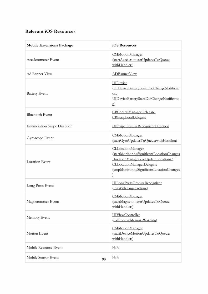
Relevant iOS Resources
Mobile Extensions Package iOS Resources
Accelerometer Event CMMotionManager (startAccelerometerUpdatesToQueue: withHandler:)
Ad Banner View ADBannerView
Battery Event
UIDevice (UIDeviceBatteryLevelDidChangeNotification, UIDeviceBatteryStateDidChangeNotification)
Bluetooth Event CBCentralManagerDelegate, CBPeripheralDelegate
Enumeration Swipe Direction UISwipeGestureRecognizerDirection
Gyroscope Event CMMotionManager (startGyroUpdatesToQueue:withHandler:)
Location Event
CLLocationManager (startMonitoringSignificantLocationChanges, locationManager:didUpdateLocations:), CLLocationManagerDelegate (stopMonitoringSignificantLocationChanges)
Long Press Event UILongPressGestureRecognizer (initWithTarget:action:)
Magnetometer Event CMMotionManager (startMagnetometerUpdatesToQueue: withHandler:)
Memory Event UIViewController (didReceiveMemoryWarning)
Motion Event CMMotionManager (startDeviceMotionUpdatesToQueue: withHandler:)
Mobile Resource Event N/A
Mobile Sensor Event N/A 98

Mobile System Event N/A
Mobile View Component N/A
Mobile View Container N/A
Mobile View Element Event N/A
Orientation Event
UIDevice (beginGeneratingDeviceOrientationNotifications, endGeneratingDeviceOrientationNotifications), UIDeviceOrientationDidChangeNotification
Pan Event UIPanGestureRecognizer (initWithTarget:action:)
Pinch Event UIPinchGestureRecognizer (initWithTarget:action:)
Proximity Event UIDevice, UIDeviceProximityStateDidChangeNotification
Rotate Event UIRotationGestureRecognizer (initWithTarget:action:)
Search View UISearchBar, UISearchDisplayController
Screen UIViewController, UINavigationController
Shake Event
UIResponder (canBecomeFirstResponder, becomeFirstResponder, motionBeganWithEvent:, motionEndedWithEvent:), UIEventSubtypeMotionShake
Swipe Event UISwipeGestureRecognizer (initWithTarget:action:)
Tap Event UITapGestureRecognizer (initWithTarget:action:)
Touch Event UIGestureRecognizer, UIGestureRecognizerDelegate
Web View UIWebView
99
Appendix C
Private Extensions Package
Accelerometer
Abstract: NoGeneralization: Sensor
This entity models the accelerometer sensor that comes with most modernmobile devices. It measures the linear velocity of the device and can beused to allow users to interact with applications by physically moving theirdevices. As part of the Mobile Device dimension, the Accelerometer could beused to decide whether a particular ViewPoint should be activated. Finally,because this entity only models the availability of the sensor on the device,it should not be used to query the actual acceleration values.
Acceleration
Abstract: YesGeneralization : Mobile Context Variable
This abstract entity groups together the linear acceleration values producedby the accelerometer of the mobile device.
Attributes
• isAvailable [Bool]: this attribute is inherited by all the specializationclasses, and indicate the acceleration of the mobile device on the x,y or z dimensions. If the sensor is not available all the acceleration
100
values will be NULL.
Acceleration-X
Abstract: NoGeneralization: Acceleration
Acceleration of the device along the x axis. If the accelerometer is notavailable the value of this variable will be NULL.
Attributes
• value [Float]: A measure in m/s2 that represent the acceleration alongthe x-axis. If the sensor is not available this attribute’s value will beNULL.
Acceleration-Y
Abstract: NoGeneralization: Acceleration
Acceleration of the device along the y axis. If the accelerometer is notavailable the value of this variable will be NULL.
Attributes
• value [Float]: A measure in m/s2 that represent the acceleration alongthe y-axis. If the sensor is not available this attribute’s value will beNULL.
Acceleration-Z
Abstract: NoGeneralization: Accelerometer
Acceleration of the device along the z axis. If the accelerometer is notavailable the value of this variable will be NULL.
Attributes
101
• value [Float] : A measure in m/s2 that represent the acceleration alongthe z-axis. If the sensor is not available this attribute’s value will beNULL.
Altitude
Abstract: NoGeneralization: Location
This variable indicates the altitude of the device with reference to the sealevel. Consequently, positive values indicate above sea level measures, whilenegative values will indicate below sea level measures.
Attitude
Abstract: YesGeneralization: Mobile Context Variable
Attitude values combine the measures of several sensors to determine theorientation of the device within a reference framework. The measures of thisvariable are characterized by the device Yaw, Pitch and Roll.
Attributes
• value [Float] : A floating point number representing the Yaw, Pitchor Roll of the device.
Battery
Abstract: YesGeneralization: Mobile Context Variable
The device battery as described by its current level and status. In contrastwith desktop applications, mobile apps are expected to deal with the chal-lenges posed by a finite power supply as well as to contribute to its optimalusage. Because of this, applications may be in interested in learning thecurrent Battery Level and decide, for instance, to execute a power intensiveoperation ( e.g. involving network access) when the battery levels are higheror the device is plugged.
Battery Level
102
Abstract: NoGeneralization: Battery
The remaining percentage of battery power.
Attributes
• value [Float]: A number between 0.0 and 1.0 that represents the re-maining percentage of battery power. This value will be NULL in casethe device is unable to report the current battery level.
Battery Status
Abstract: NoGeneralization: Battery
A Mobile Context Variable that captures the state of the device battery asdescribed by the following values: Unknown, in case the device is unable toreport the battery level; Unplugged, indicating that the device is runningon its battery; Charging, when the device is plugged to an electrical outlet;and Full, equivalent to a 1.0 Battery Level value.
Attributes
• value [Battery Status Description]: Can only take any of the followingvalues: Unknown, Unplugged, Charging or Full.
Bluetooth
Abstract: NoGeneralization : Network
The Bluetooth Mobile Context Variable, represents whether bluetooth con-nections can be established based on the availability and activation statusof the hardware component.
Attributes
• value [Bool] : This value will be true if Bluetooth networks are avail-able and the device is able to use them for data transfers. In any othercase, this variable will be false.
103
Cellular
Abstract: NoGeneralization: Network
The Cellular Mobile Context Variable represents whether cellular networksare activated and can be used for data transfer.
Attributes:
• value [Bool] : This value will be true if Cellular networks are availableand the device is able to use them for data transfers. In any othercase, this variable will be false.
Device Screen
Abstract: NoGeneralization: Named Element
This entity encompasses the screen features of a mobile device that arerequired to activate a particular Viewpoint.
Attributes
• height[Float]: the height of the screen measured in pixels
• width[Float]: the width of the screen measured in pixels.
• density[Float] : the resolution of the screen measured in pixels perinch.
Device Sensor
Abstract: YesGeneralization: Named Element
This entity encompasses the family of sensors that is included in modernmobile devices, namely: Proximity Sensor, Magnetometer, Gyroscope, Ac-celerometer, GPS, Video Camera, Microphone and Still Camera.
Direction
104
Abstract: YesGeneralization: Mobile Context Variable
The Direction variable, describes the readings of the magnetometer sensorwhich can report the orientation of the device in relation with the magneticnorth as well as the accuracy of such measures.
Enumeration Orientation Description
This enumeration describes the possible orientation modes that can be re-ported by mobile Operating Systems.
Literals
• Unknown: If the device is not able to report the current orientation.
• Portrait: If the device is held vertically with the front camera at thetop and the menu button and the bottom. This is the natural positionof the device.
• Landscape: If the device is held horizontally regardless of the positionof the front camera and menu button.
• Portrait Upside Down: If the device is held vertically with the frontcamera at the bottom and the menu button at the top.
• Landscape Right: If the device is held horizontally with the frontcamera in the right and the menu button in the left.
• Landscape Left: If the device is held horizontally with the front camerain the left and the menu button on the right.
• Face Up: If the device screen is facing the user.
• Face Down: If the device screen is not facing the user.
Enumeration Battery Status Description
This enumeration describes the possible battery status values
Literals
• Unknown: If the device is not able to report the battery status.
105
• Unplugged: If the device is currently running on battery.
• Charging: If the device is plugged to an electrical outlet and its batteryis currently charging.
• Full: If the device battery is fully charged.
GPS
Abstract: NoGeneralization: Sensor
This Entity models the GPS sensor of mobile devices.
Attributes
• isAvailable [Bool]: A true value indicates that the device in use hasGPS capabilities.
• isEnabled [Bool]: Since mobile users can decide whether they wantapplications to access their current location, this variable indicates ifthe users have allowed GPS tracking.
Gyroscope
Abstract: NoGeneralization: Sensor
The Gyroscope entity models the availability of a sensor that is able tomeasure and report changes in the angular momentum of the device.
Attributes
• isAvailable [Bool]: A true value indicates that the device in use has asensor that is able to report changes in the angular momentum of thedevice.
Magnetic Heading Direction
Abstract: NoGeneralization: Direction
106
The Heading Direction describes the orientation of the Mobile device inrelation with the magnetic north.
Attributes
• value [Float] : Device orientation measured in degrees. A value of 0o
degrees will indicate north, 90o east, 180o south and 270o west. Thisvalue will be NULL in case the device is unable to report the headingdirection.
Magnetic Heading Accuracy
Abstract: NoGeneralization: Direction
The Magnetic Heading Accuracy variable, models the perceived error in themeasurements captured by the magnetometer present in the device.
Attributes
• value [Float] : The perceived error in the magnetic heading directionmeasurement. The lower this value, the more accurate the reporteddirection.
Horizontal Accuracy
Abstract: NoGeneralization: Location
The location services in Mobile Applications are achieved by means of acombination of sensors that include GPS, cellular and wifi networks. Likein any other positioning systems, depending on reference points available,the reported data may contain some errors. This Context Variable containsthe horizontal accuracy of the reported location data.
Attributes:
• value [Float]: A value measured in meters, that describes the radiusof the error ellipse of the reported location data. Negative values
107
indicate that the device is unable to report the horizontal accuracy ofthe location measurements.
Latitude
Abstract: NoGeneralization: Location
This Context Variable describes the north-south component of a geograph-ical coordinate.
Attributes:
• value [Float]: A value measured in degrees, that describes the north-south coordinate of the user’s geographic position.
Location
Abstract: YesGeneralization: Mobile Context Variable
This abstract entity encompasses all the sensor readings that describe theuser location in terms of geographic position, speed and altitude along withthe respective measurement errors.
Longitude
Abstract: NoGeneralization: Location
This Context Variable describes the east-west component of a geographicalcoordinate.
Attributes
• value [Float]: A value measured in degrees, that describes the east-west coordinate of the user’s geographical position.
Magnetometer
108
Abstract: NoGeneralization: Sensor
The Magnetometer entity models the availability of a sensor that is able tomeasure the orientation of a mobile device with respect to the magnetic andtrue norths.
Attributes
• isAvailable [Bool]: A true value indicates that the device in use has asensor that is able to report its orientation with respect to the magneticand true norths.
Microphone
Abstract: NoGeneralization: Sensor
This entity models the availability of an input device capable of capturingaudio.
Attributes
• isAvailable [Bool]: A true value indicates that the device in use has amicrophone.
Mobile Context Variable
Abstract: YesGeneralization: Simple Context Variable
This entity provides a generalization for all the information produced by thesensors of a mobile device. Each of its specializations is concerned with thedata produced by a particular sensor and because such readings are validthroughout the different sections of the app, all the specializations haveApplication Scope.
Mobile Device
Abstract: NoGeneralization: Device
109
This entity models a modern mobile device considering the available sensorsand the main features of its screen.
Association Ends
• screens [Device Screen] (0..*): Each of the device screens supportedby a particular Viewpoint as described by their dimensions and pixeldensity.
• sensors [Device Sensor] (0..*): Each of the device sensors that arerequired on a particular Viewpoint.
Network
Abstract: YesGeneralization: Mobile Context Variable
The Network Context Variable comprises all modern network connectionsthat can be established from a mobile device. Its specializations, namelyWi-Fi, Cellular, NFC and Bluetooth networks, can be queried throughoutthe application and used by IFML designers to specify, for instance, thepreferred network that should be used to perform certain task.
Attributes
• isAvailable [Bool]: this attribute is inherited by all the specializa-tion classes, and indicate whether certain network is available for datatransfer.
NFC
Abstract: YesGeneralization: Mobile Context Variable
A key-value that describes the availability of NFC networks for data transfer.
Attributes
• value [Bool]: This value will be true if NFC networks are available andthe device is able to use them for data transfers. In any other case,this variable will be false.
110
Orientation
Abstract: NoGeneralization: Mobile Context Variable
A key-value pair that describes the current orientation of the mobile devicethrough a set of fixed values.
Association Ends
• value [Orientation Description] (0..1) : The current device orientationas described by the values of the Orientation Description enumera-tor, namely: Portrait, Landscape, Portrait Upside Down, LandscapeRight, Landscape Left, Faced Up and Face Down.
Pitch
Abstract: NoGeneralization: Attitude
A key-value pair that describes the rotation around the lateral axis of thedevice –i.e. an axis that goes from side to side [15].
Attributes:
• value[Float] : Measure in radians of the rotation of the device alongits lateral axis.
Proximity Sensor
Abstract: NoGeneralization: Sensor
This entity represents a type of sensors that is able to recognize if the user isclose to the device. Such sensor is typically used in applications that allowusers to make and receive calls because it can perceive when the device isclose to the user’s ear and trigger an event that deactivates all the touchevents avoiding in this way unintended interactions.
Attributes
111
• isAvailable [Bool]: This value will be true if the device in use has aproximity sensor. In any other case, the attribute’s value will be false.
Proximity
Abstract: NoGeneralization: Mobile Context Variable
A key-value pair that can be queried to verify whether the user is close tothe proximity sensor of the device.
Attributes
• value [Bool] : This value will be true if the user is close to the proximitysensor, and false when the user is far from it. In case the device in usedoesn’t have a proximity sensor or its unable to report the proximitystatus, the attribute’s value will be NULL.
Roll
Abstract: NoGeneralization: Attitude
A key-value pair that describes the rotation along the longitudinal axis ofthe device – i.e. an axis that goes from top to bottom [15].
Attributes
• value[Float] : Measure in radians of the rotation of the device alongits longitudinal axis.
Rotation
Abstract: YesGeneralization: Mobile Context Variable
The rotation of the device along the three spatial axis as measured by thegyroscope.
Attributes
112
• isAvailable [Bool]: this attribute is inherited by all the specializationclasses, and indicate the rotation measured along each spatial axis.
Rotation-X
Abstract: NoGeneralization: Rotation
The rotation of the device along the x-axis.
Attributes
• value[Float] : Measure in radians of the rotation of the device alongthe x-axis. If the gyroscope is not available the value of this variablewill be NULL.
Rotation-Y
Abstract: NoGeneralization: Rotation
The rotation of the device along the y-axis.
Attributes
• value[Float]: Measure in radians of the rotation of the device alongthe y-axis. If the gyroscope is not available the attribute’s value willbe NULL.
Rotation-Z
Abstract: NoGeneralization: Rotation
The rotation of the device along the y-axis.
Attributes
113
• value[Float]: Measure in radians of the rotation of the device alongthe y-axis. If the gyroscope is not available the attribute’s value willbe NULL.
Speed
Abstract: NoGeneralization: Location
The ground speed of the device as measured by the location change rateover a period of time.
Attributes
• value[Float]: Measure in meters per second of the device ground speed.If the location services are not available this attribute’s value will beNULL.
Still Camera
Abstract: NoGeneralization: Sensor
This entity models the availability of rear and back facing, still cameras.
Attributes
• front [Bool]: A true value indicates the availability of a front facingcamera that is able to snap pictures. In case the device doesn’t havea front facing camera or it is not capable of snapping pictures thisvariable will be false
• rear [Bool]: A true value indicates the availability of a back facingcamera that is able to snap pictures. In case the device doesn’t havea rear facing camera or it is not capable of snapping pictures thisvariable will be false.
True Heading Direction
114
Abstract: NoGeneralization: Direction
The Heading Direction describes the orientation of the Mobile device inrelation with the true north.
Attributes
• value [Float] : Device orientation measured in degrees. A value of 0o
degrees will indicate north, 90o east, 180o south and 270o west. Thisvalue will be NULL in case the device is unable to report the trueheading direction.
Video Camera
Abstract: NoGeneralization: Sensor
This entity models the availability of rear and back facing video cameras.
Attributes
• front [Bool]: A true value indicates the availability of a front facingcamera that is able to shoot video. In case the device doesn’t have afront facing camera or it is not capable of shooting video this variablewill be false.
• rear [Bool]: A true value indicates the availability of a back facingcamera that is able to shoot video. In case the device doesn’t have arear facing camera or it is not capable of shooting video this variablewill be false.
Vertical Accuracy
Abstract: NoGeneralization: Location
The accuracy of the reported altitude measure.
Attributes
115
• value [Float]: A value measured in meters, that describes measurementerror of the reported device altitude with respect to the level of thesea.
Wi-Fi
Abstract: NoGeneralization: Network
This key-value pair describes the availability of Wi-Fi networks for datatransfers.
Attributes
• value [Bool]: This value will be true if Wi-Fi networks are availableand the device is able to use them for data transfers. In any othercase, the attribute’s value will be false.
Yaw
Abstract: NoGeneralization: Attitude
A key-value pair that describes the rotation of the device along an axis thatis perpendicular to its surface [15].
Attributes
• value[Float]: Measure in radians of the rotation of the device along anaxis that is perpendicular to its screen.
116

Relevant iOS Resources
Private Extensions Package Entity iOS Resource
Accelerometer
UIRequiredDeviceCapabilities, CMMotionManager (accelerometerAvailable, accelerometerActive)
Acceleration CMAccelerometerData, CoreMotion
Acceleration-X CMAccelerometerData, CMMotionManager (accelerometerData)
Acceleration-Y CMAccelerometerData, CMMotionManager (accelerometerData)
Acceleration-Z CMAccelerometerData, CMMotionManager (accelerometerData)
Altitude CLLocation, CLLocationManager
Attitude CoreMotion, CMAttitude
Battery UIDevice
Battery Level UIDevice (batteryLevel)
Battery Status UIDevice (batteryLevel)
Bluetooth CoreBluetooth, CBCentralManager
Cellular Rechability
Device Screen UIDevice (model, orientation), UIUserInterfaceIdiom, UIDeviceOrientation
Device Sensor UIRequiredDeviceCapabilities
Direction CoreLocation, CLLocationManager, CLHeading
Enumeration Orientation Description UIDeviceOrientation
Enumeration Battery Status Description UIDeviceBatteryState 117

GPS UIRequiredDeviceCapabilities, CLLocationManager (locationServicesAvailable)
Gyroscope UIRequiredDeviceCapabilities, CMMotionManager (gyroAvailable, gyroActive)
Magnetic Heading Direction CLHeading (magneticHeading)
Magnetic Heading Accuracy CLHeading (headingAccuracy)
Horizontal Accuracy Horizontal Accuracy
Latitude Latitude
Location CoreLocation, CLLocationManager
Longitude CLLocation (coordinate)
Magnetometer
CMMotionManage (magnetometerActive, magnetometerAvailable), UIRequiredDeviceCapabilities
Microphone UIRequiredDeviceCapabilities
Mobile Context Variable CoreLocation, CoreMotion, CoreBluetooth
Mobile Device UIRequiredDeviceCapabilities, UIDevice
Network Rechability
NFC N/A
Orientation UIDevice, UIDeviceOrientation
Pitch CoreMotion, CMAttitude(pitch)
Proximity Sensor UIDevice (proximityMonitoringEnabled)
Proximity UIDevice (proximityState)
Roll CMAttitude (roll)
Rotation CoreMotion, CMGyroData 118
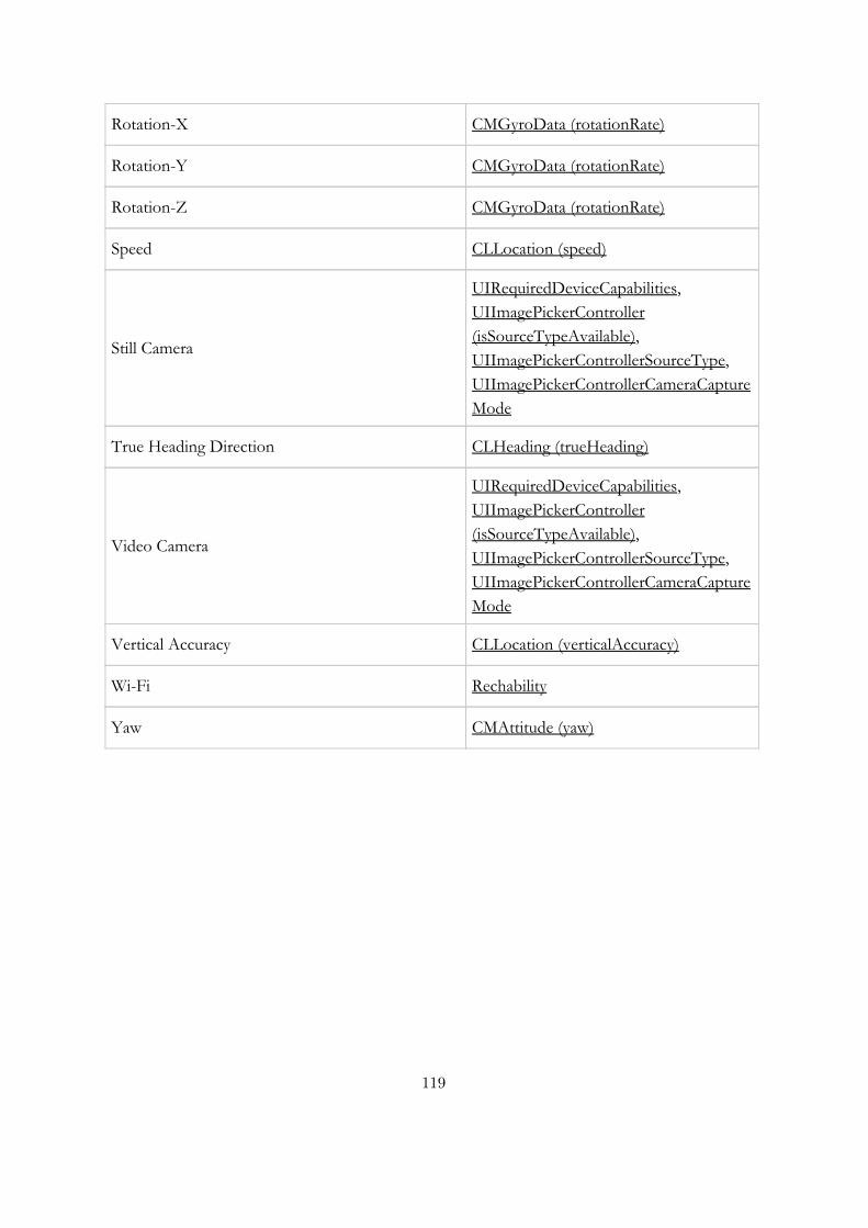
Rotation-X CMGyroData (rotationRate)
Rotation-Y CMGyroData (rotationRate)
Rotation-Z CMGyroData (rotationRate)
Speed CLLocation (speed)
Still Camera
UIRequiredDeviceCapabilities, UIImagePickerController (isSourceTypeAvailable), UIImagePickerControllerSourceType, UIImagePickerControllerCameraCaptureMode
True Heading Direction CLHeading (trueHeading)
Video Camera
UIRequiredDeviceCapabilities, UIImagePickerController (isSourceTypeAvailable), UIImagePickerControllerSourceType, UIImagePickerControllerCameraCaptureMode
Vertical Accuracy CLLocation (verticalAccuracy)
Wi-Fi Rechability
Yaw CMAttitude (yaw)
119
Note about References
Although in the Bibliography section we enumerate all the references usedduring the project, in this section we list the more valuable resources andthe role the played in shaping the final result of our project.
For the theoretical review we used the technical guides developed by AppleInc [17] [8] [7] [9] [2], and the OMG standard of IFML [21]. These resourcesprovided us with enough information and examples to grasp the main con-cepts of the target platforms.
The books authored by Martin Fowler[19], Markus Voelter [26] [25] andMarco Brambilla [18] provided the theoretical foundations that guided thecode generation process. These books were a great source of good practicesand advices for conducting a Model Driven Development effort.
Finally, the MD2 [22] project, developed at the Department of InformationSystems in the University of Munsterin, provided some inspiration for theprototype driven approach used during the project.
120
Bibliography
[1] Apple Inc. Archives and Serializations Programming Guide.https://developer.apple.com/library/ios/documentation/cocoa/conceptual/Archiving/Articles/archives.html.
[2] Apple Inc. Concepts in Objective-C Programming.https://developer.apple.com/library/ios/documentation/General/Conceptual/CocoaEncyclopedia/Introduction/Introduction.html.
[3] Apple Inc. Concurrency Programming Guide. https://developer.apple.com/library/ios/documentation/General/Conceptual/ConcurrencyProgrammingGuide/Introduction/Introduction.html.
[4] Apple Inc. Data Management - SQLite.https://developer.apple.com/technologies/ios/data-management.html.
[5] Apple Inc. File System Programming Guide. https://developer.apple.com/library/ios/documentation/FileManagement/Conceptual/FileSystemProgrammingGuide/Introduction/Introduction.html.
[6] Apple Inc. Introduction to Core Data Programming Guide.https://developer.apple.com/library/mac/documentation/Cocoa/Conceptual/CoreData/cdProgrammingGuide.html.
[7] Apple Inc. iOS Programming Guide. https://developer.apple.com/library/ios/documentation/iPhone/Conceptual/iPhoneOSProgrammingGuide/Introduction/Introduction.html.
[8] Apple Inc. iOS Technology Review. https://developer.apple.com/library/ios/documentation/Miscellaneous/Conceptual/iPhoneOSTechOverview/Introduction/Introduction.html.
[9] Apple Inc. Programming with Objective-C. https://developer.apple.com/library/ios/documentation/Cocoa/Conceptual/ProgrammingWithObjectiveC/Introduction/Introduction.html.
121
[10] Apple Inc. Property lists Programming Guide.https://developer.apple.com/library/ios/documentation/Cocoa/Conceptual/PropertyLists/Introduction/Introduction.html.
[11] Apple Inc. Transitioning to ARC Release Notes.https://developer.apple.com/library/ios/releasenotes/objectivec/rn-transitioningtoarc/introduction/introduction.html.
[12] Apple Inc. URL Loading System Programming Guide.https://developer.apple.com/library/ios/documentation/Cocoa/Conceptual/URLLoadingSystem/URLLoadingSystem.html.
[13] Apple Inc. View Controller Programming Guide.https://developer.apple.com/library/ios/featuredarticles/ViewControllerPGforiPhoneOS/AboutViewControllers/AboutViewControllers.html.
[14] Apple Inc. Views Programming Guide.https://developer.apple.com/library/ios/documentation/Cocoa/Conceptual/PropertyLists/Introduction/Introduction.html.
[15] Apple Inc. CMAttitude Class Reference.https://developer.apple.com/library/IOs/documentation/CoreMotion/Reference/CMAttitude Class/index.html, 2011.
[16] Apple Inc. ADBannerView Class Reference.https://developer.apple.com/LIBRARY/ios/documentation/UserExperience/Reference/ADBannerView Ref/index.html, 2013.
[17] Apple Inc. App Programming Guide for iOS. https://developer.apple.com/library/ios/documentation/iPhone/Conceptual/iPhoneOSProgrammingGuide/iPhoneAppProgrammingGuide.pdf,2014.
[18] Marco Brambilla, Jordi Cabot, and Manuel Wimmer. Model-DrivenSoftware Engineering in Practice. Morgan and Claypool Publishers,2012.
[19] Martin Fowler. Domain-Specific Languages. Addison-WesleyProfessional, October 2010.
[20] Google. Google Mobile Ads.https://developer.android.com/google/play-services/ads.html, 2013.
[21] Object Management Group. Interaction flow modeling language(ifml). http://www.omg.org/spec/IFML/1.0, February 2014.
122
[22] Herbert Kuchen Henning Heitkotter, Tim A. Majchrzak.Cross-platform model-driven development of mobile applications withmd2, 2013.
[23] International Data Corporation (IDC). Smartphone OS Market Share,Q2 2014.http://www.idc.com/prodserv/smartphone-os-market-share.jsp, 2014.
[24] Object Management Group (OMG). Unified Modeling Language.http://www.omg.org/spec/UML/2.4.1/, 2011.
[25] Markus Voelter. A catalog of patterns for program generation, 2003.
[26] Markus Voelter. DSL Engineering: Designing, Implementing andUsing Domain-Specific Languages. Create Space IndependentPublishing Platform, 2013.
123

Acknowledgments
This project represents the climax of a journey that started two years ago.A journey that I couldn’t have completed without the help and support ofmany people that kept me sane through the toughest moments of this path.
First, and foremost I would like to thank my mum. For her unconditionalsupport, guidance and wise advices. For being there, for not giving up onme, and for all the sacrifices that my life abroad has implied for her.
To my girlfriend and her parents. For teaching me that, like building ahouse, seeing the end of a project is an endeavour that needs to be facedbrick by brick.
To all my cousins but specially to Sebastian, from whom I learned how tolive with courage and to never give up in spite of the challenges that lifeputs in our paths.
I would also like to thank my university back home, Pontificia UniversidadJaveriana, and my sponsor, Colfuturo, for making possible this marvelousexperience, and for supporting me in every step of the journey.
Finally I want to express my gratitude to my supervisor, Marco Brambilla,for being always available for discussion and for helping me drive thisproject to a good end.
124