OPTICAL MICROSCOPE INVERTED OPTICAL MICROSCOPE FLUORESCENCE MICROSCOPE

Nikon
Polarizing Microscope
OPTIPHOT -POLINSTRUCTIONS
NIPPON KOGAKU K. K.
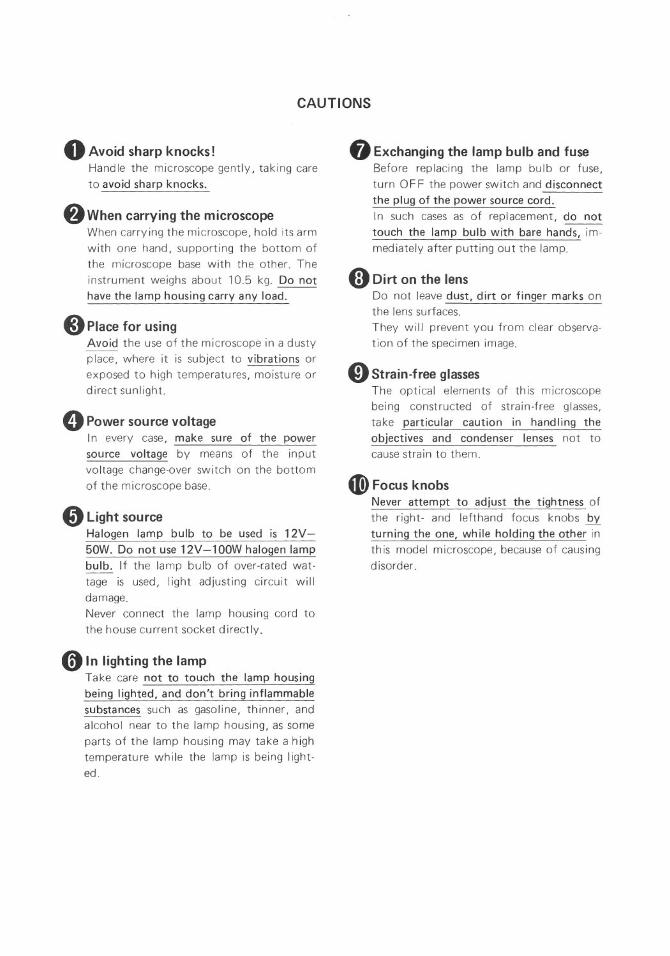
CAUTIONS
oAvoid sharp knocks!Handle the microscope gently, taking careto avoid sharp knocks.
f}When carrying the microscopeWhen carrying the microscope, hold its armwith one hand, supporting the bottom ofthe microscope base with the other. Theinstrument weighs about 10.5 kg. Do nothave the lamp housing carry any load.
8Place for usingAvoid the use of the microscope in a dustyplace, where it is subject to vibrations orexposed to high temperatures, moisture ordirect sunlight.
oPower source voltageIn every case, make sure of the powersource voltage by means of the inputvoltage change-over switch on the bottomof the microscope base.
oLight sourceHalogen lamp bulb to be used is 12V-50W. Do not use 12V-l OOWhalogen lampbulb. If the lamp bulb of over-rated wat-tage is used, light adjusting circuit willdamage.Never connect the lamp housing cord tothe house current socket directly.
o In lighting the lampTake care not to touch the lamp housingbeing lighted, and don't bring inflammablesubstances such as gasoline, thinner, andalcohol near to the lamp housing, as someparts of the lamp housing may take a hightemperature while the lamp is being light-ed.
oExchanging the lamp bulb and fuseBefore replacing the lamp bulb or fuse,turn 0 FF the power switch and disconnectthe plug of the power source cord.In such cases as of replacement, do nottouch the lamp bulb with bare hands, im-med iately after putting out the lamp.
«;) Dirt on the lensDo not leave dust, dirt or finger marks onthe lens surfaces.They will prevent you from clear observa-tion of the specimen image.
oStrain-free glassesThe optical elements of this microscopebeing constructed of strain-free glasses,take particular caution in handling theobjectives and condenser lenses not tocause strain to them.
4D> Focus knobsNever attempt to adjust the tightness ofthe right- and lefthand focus knobs byturning the one, while holding the other inth is model microscope, because of causi ngdisorder.
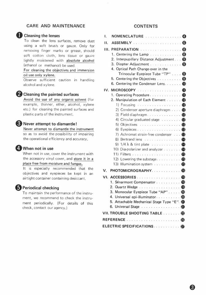
CARE AND MAINTENANCE CONTENTS
·············0....... 0·······8
NOMENCLATURE
II. ASSEMBLY.
I.
III. PREPARATION1. Centering the Lamp 82. Interpupillary Distance Adjustment 03. Diopter Adjustment 04. Optical Path Change-over in the
Trinocular Eyepiece Tube "TP" 05. Centering the Objectives 06. Centering the Condenser Lens 4@
IV. MICROSCOPY 411. Operating Procedure 412. Manipulation of Each Element ~
1) Focusing ~2) Condenser aperture diaphragm ~3) Field diaphragm ~4) Circular graduated stage ~5) Objectives 4J)
6) Eyepieces 4J)
7) Achromat strain-free condenser 4J)
8) Bertrand lens 4D9) 1/4 A & tint plate 4D
10) Dia-polarizer and analyzer 4D
11) Filters G)12) Lowering the substage G)13) Illumination system G)
V. PHOTOMiCROGRAPHy 4D
VI. ACCESSORIES ~1. Senarmont Compensator ~2. Quartz Wedge ~3. Monocular Eyepiece Tube "AP" W4. Universal epi-illuminator W5. Attachable Mechanical Stage Type "E". ~6. Universal Stage ~
VII. TROUBLE SHOOTING TABLE ~
REFERENCE ~
ELECTRIC SPECIFICATIONS 0
8Cleaning the painted surfacesAvoid the use of any organic solvent (forexample, thinner, ether, alcohol, xyleneetc.) for cleaning the painted surfaces andplastic parts of the instrument.
oCleaning the lensesTo clean the lens surfaces, remove dustusing a soft brush or gauze. Only forremoving finger marks or grease, shouldsoft cotton cloth, lens tissue or gauzelightly moistened with absolute alcohol(ethanol or methanol) be used.For cleaning the objectives and immersionoil use only xylene.Observe sufficient caution in handlingalcohol and xylene.
8Never attempt to dismantle!Never attempt to dismantle the instrumentso as to avoid the possibility of impairingthe operational efficiency and accuracy.
oWhen not in useWhen not in use, cover the instrument withthe accessory vinyl cover, and store it in aplace free from moisture and fungus.It is especially recommended that theobjectives and eyepieces be kept in anairtight container containing desiccant.
oPeriodical checkingTo maintain the performance of the instru-ment, we recommend to check the instru-ment periodically. (For details of thischeck, contact our agency.)
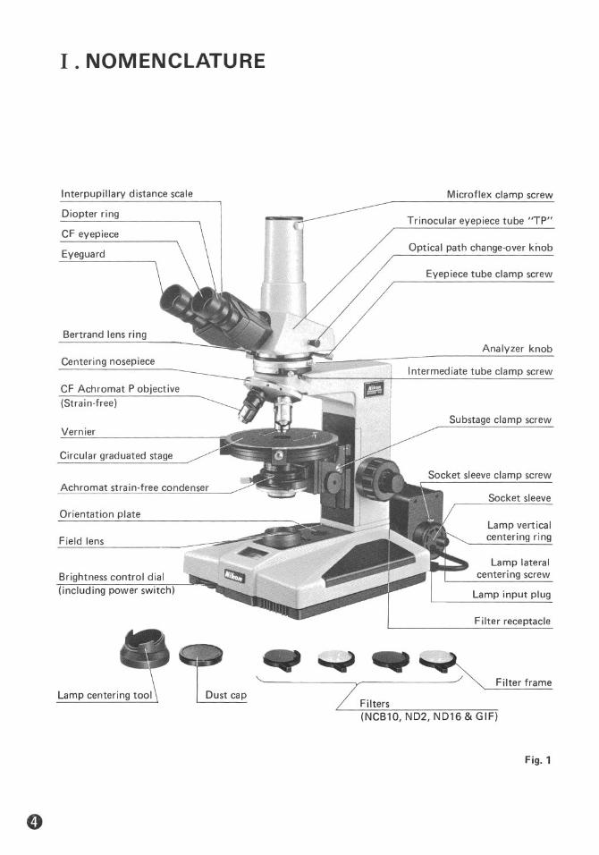
I .NOMENCLATURE
Interpupillary distance scale
Diopter ring
CF eyepiece
Eyeguard
Bertrand lens ring
Centering nosepiece
CF Achromat P objective(Stra in-free)
Vernier
Circular graduated stage
Achromat strain-free condenser
Orientation plate
Field lens
Brightness control dial(including power switch)
Microflex clamp screw
Trinocular eyepiece tube "TP"
Optical path change-over knob
Eyepiece tube clamp screw
Analyzer knob-----------I Intermediate tube clamp screw
111'1,Substage clamp screw
Socket sleeve
Lamp verticalcentering ring
Lamp lateralcentering screw
Lamp input plug
Filter receptacle
Filter frame
~ ND16&GIFI(NCB10. ND2.
Dust capLamp centering tool
Fig. 1

Analyzer rotation ring
Analyzer clamp screw
Intermediate tube "P"
Nosepiece clamp screw
45° click stop lever
Condenser focus knob
Coarse focus knob
Fine focus knob
Lamp housing
Lamp housingclamp screw
Arm rest
-..
Compensator slot
1/4 A & tint plate
Nosepiece centering screw
Specimen clip
Condenser aperturediaphragm control ring
Dia-polarizer-------Condenser clamp screw
Brightness indicator
Field diaphragm control ring
X-POL stand
Fig.2
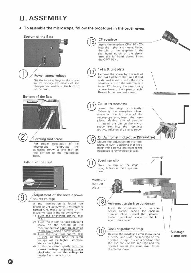
II. ASSEMBLY• To assemble the microscope, follow the procedure in the order given:
Substageclamp scre,
Achromat strain-free condenserInsert the condenser into the con-denser carrier, facing the aperturenumber plate toward the operator.Fasten the clamp screw on the leftside of the carrier.
Circular graduated stageRelease the substage clamp screw usinga driver, and sl ide the substage on thedovetail fitting. In such a position thatthe top ends of the substage and thedovetail are at the same level, fastenthe clamp screw.
CF eyepieceInsert the eyepiece CFW 10XCMinto the right-hand sleeve, fittingthe pin of the eyepiece in theright-hand notch of the sleeve.Into the left-hand sleeve, inserttheCFW10X.
1/4 A & tint plateRemove the screw by the side ofthe 1/4 "A. plate of the 1/4 "A. & tintplate and insert it into the com-pensator slot of the intermediatetube "P", facing the positioninggroove toward the operator side.Reattach the removed screw.
Specimen clipPlace the clip on the stageusing holes on the stage sur-face.
@
Aperturenumberplate
@ Centering nosepiece17 Lower the stage sufficiently.Releasing the nosepiece clampscrew on the left side of themicroscope arm, insert the nose-piece. Making sure of positivefitting of the pin on the micro-scope arm into the nosepiecegroove, refasten the clamp screw.
@
@6CF Achromat P objective (Strain-free)Mount the objectives on the nose-piece in such positions that theirmagnifying power increases as thenosepiece is revolved clockwise.
@
lowest power
Leveling foot screwFor stable installation of themicroscope, manipulate theadjusting screw at one foot onthe bottom of the microscopebase.
Power source voltageSet the input voltage to the powersource voltage by means of thechange-over switch on the bottomof the base.
If the illumination is found toobright or unstable, when the switch isturned ON, make adjustment of thelowest voltage in the following way:1) Turn the brightness control dialto OFF.
2) Turn the lowest voltage adjustingscrew on the bottom of themicroscope base counterclockwiseto the limit, using a screw driver.
3) Turn the brightness control dialto ON_ At this time, the lampvoltage will be highest, immedi-ately after lighting.
4) In this condition, gently turn thelowest voltage adjustingsc;:ewclockwise, to set the voltage tonearly 4 on the ind icator.
Bottom of the Base
Bottom of the Base~ -------~
Bottom of the Base
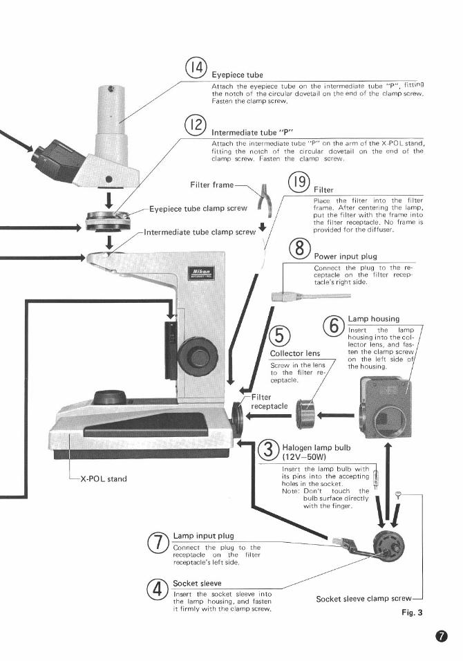
Eyepiece tubeAttach the eyepiece tube on the intermediate tube "P", fittingthe notch of the circular dovetail on the end of the clamp screw.Fasten the clamp screw.
Intermed iate tube "P"Attach the intermediate tube "P" on the arm of the X-POL stand,fitting the notch of the circular dovetail on the end of theclamp screw. Fasten the clamp screw.
Lamp input plugConnect the plug to thereceptacle on the filterreceptacle's left side.
® Lamp housingInsert the lamphousing into the col-lector lens, and fas-ten the clamp screwon the left side ofthe housing.
@ FilterPlace the filter into the filterframe. After centering the lamp,put the filter with the frame intothe filter receptacle. No frame isprovided for the diffuser.
® Power input plugConnect the plug to the re-ceptacle on the fi Iter recep-tacle's right side.
Insert the lamp bulb withits pins into the acceptingholes in the socket.Note: Don't touch the
bulb surface directlywith the fi nger.
f3\ Halogen lamp bulb~ (12V-50W)
Filter frame
@
@
Eyepiece tube clamp screw
Socket sleeveInsert the socket sleeve intothe lamp housing, and fastenit firmly with the clamp screw.
Socket sleeve clamp screw
Fig. 3

III. PREPARATION
Lamp housingclamp screw
Filamentimage
Condenseraperturediaphragm
Socket sleeveclamp screwLamp verticalcentering ring
Lamp lateralcentering screw
/
Fig. 6
7) Release the socket sleeve clamp screw (Fig.6). Turning the lamp lateral centering screwand vertical centering ring, bring the fila-ment image to the center, as shown inFig.7.
Fig. 7
8) As shown in Fig. 8, put the diffuser, withits matte surface faced toward the micro-scope stand, into the filter receptaclewhich is the closest to the microscopestand.
Fig. 8
The above centering procedure should be car-ried out, when replacing the lamp bulb.
Lamp housing
Lampcenteringtool
1. Centering the Lamp
ND filter
1) Connect the power source cord to thesocket.
2) Turn the brightness control dial to switchON and adjust the voltage to 6 on theindicator.
3) Place the specimen on the stage, and focuson the specimen using lOx objective. Inthis case, open the condenser aperture andfield diaphragms to the largest extent.
4) Roughly center the condenser lens usinglOX objective, following the proceduresgiven on P. 10- 6.
5) Put the lamp centering tool on the fieldlens and onto the tool place a NO filter.
(Fig. 4)
Fig. 4
6) Stop down the condenser aperture dia-phragm, release the lamp housing clampscrew, and move the lamp housing backand forth (Fig. 5), until a sharp image ofthe lamp filament appears on the aperturediaphragm surface, which can be seen bythe reflection from the NO filter.
Fig.5

Fig. 13
Vertical phototube: 86%
Observation Observationtube: 100% tube: 14%+-- --+
~OPtical pathchange-over knob
Fig. 12
Fig.11
*Since the CF eyepieces are of high eye-point type, it is not necessary for the userputting on his spectacles to remove them.Only fold down the eyeguard rubber.
(Fig.13)
4. Optical Path Change-over in theTrinocular Eyepiece Tube "TP"
(Fig. 11)
5. Centeringthe Objectives1) Place the specimen on the stage, and focus
on the specimen. Bring an appropriate tar-get to the center of the cross lines in theeyepiece.
2) Insert the centering tools in the centeringscrews on the nosepiece. (F ig. 14)
2. Interpupillary DistanceAdjustment IPlace a specimen on the stage, and focus on thespecimen.As shown in Fig. 9, adjust the interpupillarydistance, so that both the right and left view-fields become one. '
Fig. 9
Fig. 10
3. Diopter AdjustmentRotate the diopter ring on the eyepiece CFWlOx CM until the cross lines are seen clear.
(Fig. 10)
(For b inocu lar observation)1) Mount the specimen on the stage. Swing
the objective 10 x into position, and bringthe specimen image into focus looking intothe right-hand eyepiece.
2) Witll.Out manipulating the coarse-and-finefocus knob, turn the diopter ring on theleft-hand eyepiece to focus on the speci-men.
Fig. 14

3) Rotate the stage about 1800, and the targetis displaced from the center of the crosslines. Move the objective using the center-ing tools so that the center of the crossIines comes to one half position of thedisplacement of the target. (F ig. 15)
Rotate1800
Target-A halfpositionof thedisplacement
Image of field
[~:a~~~~~~~'\
),,>J":/
Eyepieceviewfield stop
Fig. 16
Fig. 15
• Repeat the above procedure two or threetimes, and the rotation center of the stagecoincides with the cross Iines center .
• Carry out centering for each objective.
6. Centering the Condenser Lens1) Close the field diaphragm in the micro-
scope base to its smallest size by means ofthe field diaphragm control ring. Rotatethe condenser focus knob to move thecondenser vertically so that a sharp imageof the field diaphragm is formed on thespecimen surface.
2) Bring the field diaphragm image to thecenter of the field of view by means ofthe condenser centering screws.
(Fig. 16-1IJ)3) Change over to the objective 40 x, and
adjust the field diaphragm so that theimage of the diaphragm is about the sameas the eyepiece viewfield stop, as shown inFig. 16-~. If not centered, use the con-denser centering screws again.
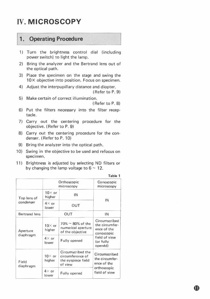
IV. MICROSCOPY
11. Operating Pr0Cf}dur~1) Turn the brightness control dial (including
power switch) to light the lamp.2) Bring the analyzer and the Bertrand lens out of
the optical path.3) Place the specimen on the stage and swing the
10X objective into position. Focus on specimen.4) Adjust the interpupillary distance and diopter.
(Refer to P. 9)5) Make certain of correct illumination.
(Refer to P. 8)6) Put the filters necessary into the filter recep-
tacle.7) Carry out the centering procedure for the
objective. (Refer to P. 9)8) Carry out the centering procedure for the con-
denser. (Refer to P. 10)9) Bring the analyzer into the optical path.10) Swing in the objective to be used and refocus on
specimen.11) Brightness is adjusted by selecting ND filters or
by changing the lamp voltage to 6 ~ 12.Table 1
OrthoscopicConoscopicmicroscopy
microscopy
10X orINTop lens ofhigher
INcondenser 4X orOUTlowerBertrand lens
OUTIN
Circumscribed10X or
70% ~ 80% of thethe circumfer-numerical aperture ence of theAperture
higherof the objectiveconoscopicdiaphragm 4X or
field of viewFully opened
(or fullylower opened)Circumscribed the
Circumscribed10X orcircumference of
the circumfer-Fieldhigherthe eyepiece fieldence of thediaphragm
of vieworthoscopic4X or Fully openedfield of view
lower

2. Manipulation of Each Element1) Focusing• The relation between the direction of rota-
tion of the focus knobs and that of verticalmovement of the stage is as indicated inFig. 17.
Torque adjustmentringFine focusknobCoarse focusknob
Fig. 17
• One rotation of the fine focus knob movesthe stage 0.1 mm.The graduation on th is focus knob ~divided into 111m.One rotation of the coarse focus knobmoves the stage 4.7mm.
• Tightness of the coarse-fine focus knobhaving been properly adjusted by themanufacturer, it should never be readjustedin this model microscope by turning theone knob while holding the other.
2) Condenser aperture diaphragm (A dia-phragm)
(1) Orthoscopic microscopy• The condenser aperture diaphragm is
provided for adjusting the numericalaperture (N.A.) of the illuminating systemof microscope.In genera I, when it is stopped down to 70~ 80% of the numerical aperture of theobjective, a good image of appropriatecontrast will be obtained. (Fig. 18)
Exit pupilof objective
Aperturediaphragm
Size of the condenser aperture diaphragm
Fig. 18• Remove the eyepiece from the eyepiece
tube, adjust the size of the diaphragm,
observing the image of the diaphragmwhich is visible on the bright circle of exitpupil of objective inside.
• When swinging out the top lens of the con-denser (for microscopy using 4x or lowerobjective), fully open the condenseraperture diaphragm.
(2) Conoscopic microscopy• In conoscopic microscopy, the condenser
aperture diaphragm works as a field dia-phragm on the conoscopic image surface.Stop down the diaphragm to such anextent that it circumscribes the circumfer-ence of the field of view of the conoscopicimage (exit pupil of objective) to shut outthe stray light.
3) Field diaphragm (F diaphragm)• The field diaphragm is used for determin-
ing the illuminated area on the specimensurface in relation to the field of view ofthe microscope. Generally, it is stoppeddown to such an extent that the circum-ference of the illuminated area circum-scribes that of the eyepiece field of view.[Note] This diaphragm does not work as
the field diaphragm when thecondenser top lens is swung outof the optical path. In this casethe diaphragm is recommendedto be fully opened because thenumerical aperture of the illumi-nator will be cut off when thisdiaphragm is excessively stoppeddown.
4) Circular graduated stage• The rotation angle of the stage is readable
with the accuracy of 0.10 via a pairedvern ier scales.When the reading with one of the vernierscales is interrupted by the attachablemechanical stage type "E", read the othervernier and add ±90° to the reading .
• The 450 click-stop device comes to act atevery 450 rotation, starting from a positionwhere the click stop lever has been pulledtoward the operator, giving convenience inswitching over the observation from acrossed Nicols position to a diagonal posi-tion. (Fig. 19)
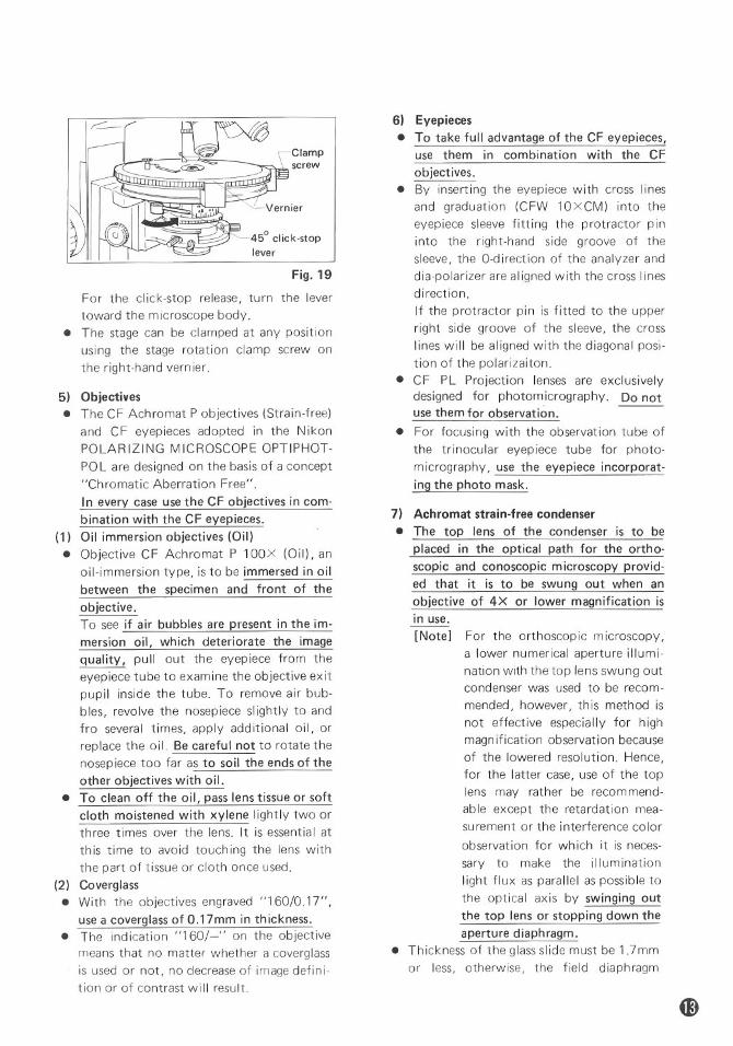
Clampscrew
45° click-stoplever
Fig. 19
For the click-stop release, turn the levertoward the microscope body.
• The stage can be clamped at any positionusing the stage rotation clamp screw onthe right-hand vernier.
5) Objectives• The CF Achromat P objectives (Strain-free)
and CF eyepieces adopted in the NikonPOLARIZING MICROSCOPE OPTIPHOT-POL are designed on the basis of a concept"Chromatic Aberration Free".In every case use the CF objectives in com-bination with the CF eyepieces.
(1) Oil immersion objectives (Oil)• Objective CF Achromat P 100X (Oil), an
oil-immersion type, is to be immersed in oilbetween the specimen and front of theobjective.To see if air bubbles are present in the im-mersion oil, which deteriorate the imagequality, pull out the eyepiece from theeyepiece tube to examine the objective exitpupil inside the tube. To remove air bub-bles, revolve the nosepiece slightly to andfro several times, apply additional oil, orreplace the oil. Be careful not to rotate thenosep iece too far as to soil the ends of theother objectives with oil.
• To clean off the oil, pass lens tissue or softcloth moistened with xylene lightly two orthree times over the lens. It is essential atthis time to avoid touching the lens withthe part of tissue or cloth once used.
(2) Coverglass• With the objectives engraved "160/0.17",
use a coverglass of O.17mm in thickness.• The indication "160/-" on the objective
means that no matter whether a coverglassis used or not, no decrease of image defini-tion or of contrast will result.
6) Eyepieces• To take full advantage of the CF eyepieces,
use them in combination with the CFobjectives.
• By inserting the eyepiece with cross linesand graduation (CFW 10XCM) into theeyepiece sleeve fitting the protractor pininto the right-hand side groove of thesleeve, the O-direction of the analyzer anddia-polarizer are al igned with the cross linesdirection.If the protractor pin is fitted to the upperright side groove of the sleeve, the crosslines will be aligned with the diagonal posi-tion of the polarizaiton.
• CF PL Projection lenses are exclusivelydesigned for photom icrography. Do notuse them for observation. ---
• For focusing with the observation tube ofthe trinocular eyep iece tube for photo-micrography, use the eyepiece incorporat-ing the photo mask.
7) Achromat strain-free condenser• The top lens of the condenser is to be
placed in the optical path for the ortho-scopic and conoscopic microscopy provid-ed that it is to be swung out when anobjective of 4X or lower magnification isin use.[Note] For the orthoscopic microscopy,
a lower numerical aperture illumi-nation with the top lens swung outcondenser was used to be recom-mended, however, this method isnot effective especially for highmagn ification observation becauseof the lowered resolution. Hence,for the latter case, use of the toplens may rather be recommend-able except the retardation mea-surement or the interference colorobservation for wh ich it is neces-sary to make the illuminationlight flux as parallel as possible tothe optical axis by swinging outthe top lens or stopping down theaperture diaphragm.
• Thickness of the glass slide must be 1.7mmor less, otherwise, the field diaphragm
might fail to focus its image on the speci-men.
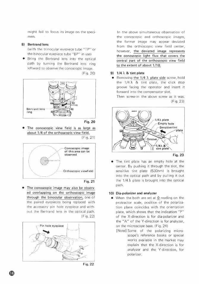
8) Bertrand lens(with the trinocular eyepiece tube "TP" orthe binocular eyepiece tube "BP" in use)
• Bring the Bertrand lens into the opticalpath by turning the Bertrand lens ringleftward to observe the conoscopic image.
(Fig. 20)
In the above simultaneous observation ofthe conoscopic and orthoscopic images,the former image may appear deviatedfrom the orthoscopic view field center,however, the deviated image representsthe conoscopic light flux that covers thecentral part of the orthoscopic view fieldto the extent of about 1/18.
9) 1/4 'A & tint plate• Removing the 1/4 'A plate side screw, hold
the 1/4 'A & tint plate, the cI ick stopgroove facing the operator and insert itforward into the compensator slot.Then screw-in the above screw as it was.
(Fig.23)
Fig. 23
• The tint plate has an empty hole at thecenter. By pushing it through the slot, thesensitive tint plate (530nm) is broughtinto the optical path and by pu IIing it outthe 1/4 'A p late is brought into the opticalpath.
10) Dia-polarizer and analyzer• When the both are set at ~ read ing on the
protractor scale, position of the polariza-tion plane coincides with the orientationplate, which shows that the indication "P"of the X-direction is for dia-polarizer andthe "A" of the V-direction is for analyzer,on the microscope base. (Fig. 24)[Note] Some of the polarizing micro-
scope's reference books or specialworks available in the market mayexplain that the X-direction is foranalyzer and the V-direction, forpolarizer.
Conoscopic imageof this area can beobserved
--Orthoscopic viewfield
• The conoscopic view field is as large asabout 1/4 of the orthoscopic view field.
(Fig. 21)
Bertrand lensring
Fig. 20
Fig. 21
• The conoscopic image may also be observ-ed overlapping on the orthoscopic imagethrough the binocular observation, one ofthe paired eyepieces being replaced withthe accessory pin hole eyepiece and with-out the Bertrand lens in the optical path.
(Fig.22)
Fig. 22
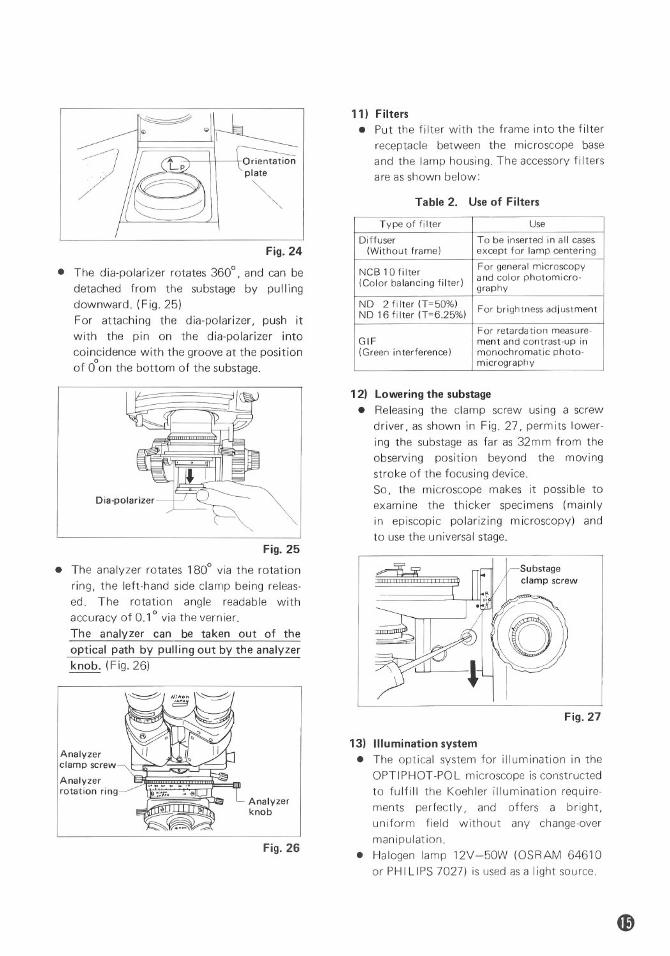
Orientationplate
~
Fig. 24
• The dia-polarizer rotates 3600, and can bedetached from the substage by pullingdownward. (Fig. 25)For attaching the dia-polarizer, push itwith the pin on the dia-polarizer intocoincidence with the groove at the positionoof 0 on the bottom of the substage.
11) Filters• Put the filter with the frame into the filter
receptacle between the microscope baseand the lamp housing. The accessory filtersare as shown below:
Table 2. Use of Filters
Type of filter Use
DiffuserTo be inserted in all cases
(Without frame)except for lamp centering
NCB 10 filter
For general microscopy
(Color balancing filter)
and color photomicro-graphyND
2 filter (T=50%)For brightness adjustmentND 16 filter (T=6.25%)
For retardation measure-GIFment and contrast-up in
(Green interference)monochromatic photo-
micrography
Fig. 26
Fig. 25
• The analyzer rotates 1800 via the rotationring, the left-hand side clamp being releas-ed. The rotation angle readable withaccuracy of 0.10 via the vernier.The analyzer can be taken out of theoptical path by pulling out by the analyzerknob. (Fig. 26)
Substageclamp screw
rtY~
Fig. 27
12) Lowering the substage• Releasing the clamp screw using a screw
driver, as shown in Fig. 27, permits lower-ing the substage as far as 32mm from theobserving position beyond the movingstroke of the focusing device.So, the microscope makes it possible toexamine the thicker specimens (mainlyin episcopic polarizing microscopy) andto use the universal stage.
13) Illumination system• The optical system for illumination in the
OPTIPHOT-POL microscope is constructedto fulfill the Koehler illumination require-ments perfectly, and offers a bright,uniform field without any change-overmanipulation.
• Halogen lamp 12V-50W (OSRAM 64610or PH ILIPS 7027) is used as a Iight source.
Analyzerknob
Dia-polarizer
Analyzerclamp screwAnalyzerrotation ring

V.PHOTOMICROGRAPHY
Prepare the following equipments in addition tothe OPTIPHOT-POL microscope main body.* Nikon Microflex* Trinocular eyepiece tube "TP"* CF PL Projection lens
1. CF PI:.Projection LensesThe combined use of the CF P objectives andCF PL Projection lenses is essential.For the same total magnification, select a com-bination of the highest possible objective powerand lowest possible projection lens power toachieve the utmost image definition andcontrast.
2. Illumination1) Checking the illu mination
Unevenness in the illumination will showup more conspicuously in photomicro-graphy than in observation. Consequently,before taking a photograph, recheck thepositioning and centering of the lamp andthe correct adjustment of the condenser.
2) Selection of voltage and filterThe color temperature of the light sourcevaries with the voltage being used. There-fore, in color photomicrography, theselection of voltage and filter is essential(for the result to be obtained).
Table 3. Standard Selection
Film VoltageFilter
Daylight9NCB 10 is to be used
Colortype
filmTungsten
type
8Remove NCB 10
Remove NCB 10Monochrome film
Over 6Contrast fi Iter(green),etc. is usable
Table 3 shows the standard combination.Depending upon the make of the film,different color renditions may result. It isrecommended that in addition to the NCB10 filter a color compensation filter (CCfilter), available from the film manufac-tu rer, be used.
3. Shutter SpeedDesirable shutter speeds for least vibration are1/4 ~ 1/15 sec. Adjustment of the image bright-ness for color photomicrography should bemade by means of the NO filters.
4. Manipulation of Field and ApertureDiaphragm
In photomicrography, the adjustment of thefield diaphragm is important for the purpose oflimiting extraneous light which causes flare inthe microscope image. Stop down the dia-phragm so as to get an illuminated area slightlylarger than that of the picture field. By adjust-ing the aperture diaphragm, a change of depthof focus, contrast and resolution of image isattainable. Select a size suited to the purpose.Generally speaking, the aperture diaphragm, isproperly stopped down to 70 ~ 80% of theaperture of the objective being used.
5. FocusingFocusing for photomicrography can be donewith the observation tube of the trinoculareyepiece tube "TP" or by using the Microflexfinder.
1) Adjust diopter• Using binocular of eyepiece tube:
Use 4X or 1OX objective.Insert the mask eyepiece into either ofright or left eyepiece sleeve that is ac-customed to usual use. Adjust the diopterring to bring the double cross line in theview field center into focus. (Fig. 28)Then focus the specimen image also on thecentral area of the mask by means of thefocus knob of the microscope.The diopter of another eyepiece is to beadjusted by focusing specimen rotating thediopter ring without using the microscopefocus knob.Rotate the mask eyepiece so as the maskpositions as shown in Fig. 32.
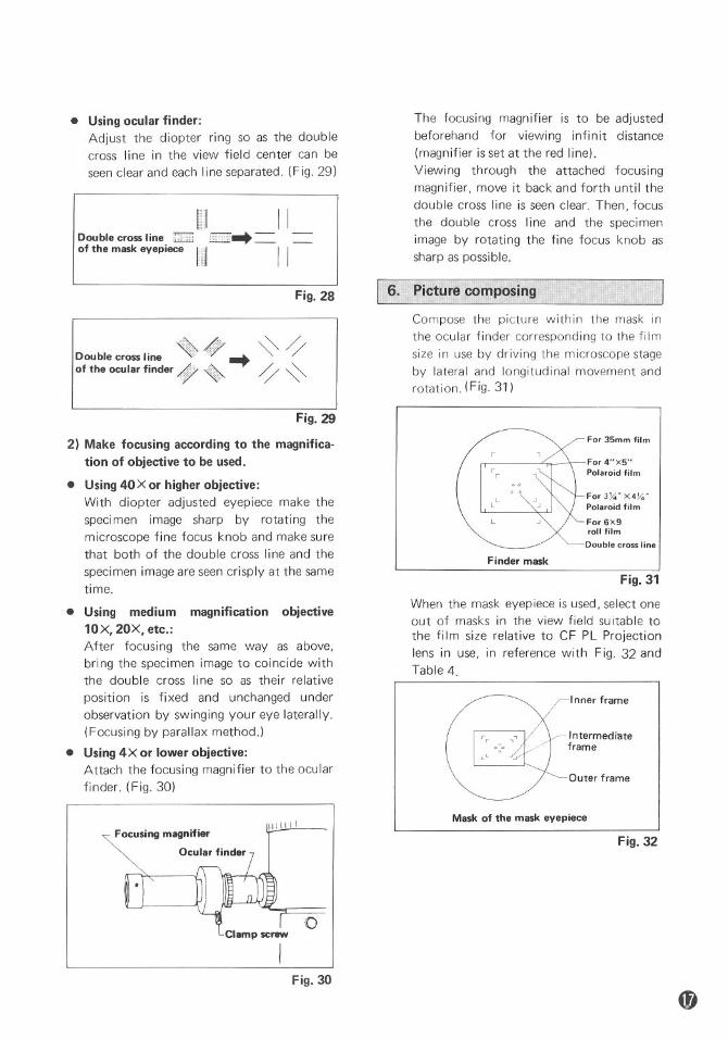
• Using ocular finder:Adjust the diopter ring so as the doublecross line in the view field center can beseen clear and each line separated. (Fig. 29)
II II. _ = ....••-Dou ble cross line ;;.::";"" l2lll2....,.. __
of the mask eyepiece /il111 II
The focusing magnifier is to be adjustedbeforehand for viewing infinit distance(magnifier is set at the red line).Viewing through the attached focusingmagnifier, move it back and forth until thedouble cross line is seen clear. Then, focusthe double cross line and the specimenimage by rotating the fine focus knob assharp as possible.
Fig. 28
Double cross Ii.ne «> 4)7 -+ ~ 'lof the ocular finder q)P ~ 'l~
I 6. Picture composingCompose the picture within the mask inthe ocular finder corresponding to the filmsize in use by driving the microscope stageby lateral and longitudinal movement androtation. (Fig. 31)
Fig. 29
Outer frame
Inner frame
Intermediateframe
For 35mm film
For 4"x5"Polaroid film
For 3~" X 4X;"Polaroid film
For 6X9roll filmDouble cross line
Finder mask
When the mask eyepiece is used, select oneout of masks in the view field suitable tothe film size relative to CF PL Projectionlens in use, in reference with Fig. 32 andTable 4.
Fig. 31
2) Make focusing according to the magnifica-tion of objective to be used.
• Using 40X or higher objective:With diopter adjusted eyepiece make thespecimen image sharp by rotating themicroscope fine focus knob and make surethat both of the double cross line and thespeci men image are seen crisp Iy at the sametime.
• Using medium magnification objective10X, 20X, etc.:After focusing the same way as above,bring the specimen image to coincide withthe double cross line so as their relativeposition is fixed and unchanged underobservation by swinging your eye laterally.(Focusing by parallax method.)
• Using 4X or lower objective:Attach the focusing magnifier to the ocularfinder. (Fig. 30)
o
Mask of the mask eyepiece
Fig. 32
Fig. 30
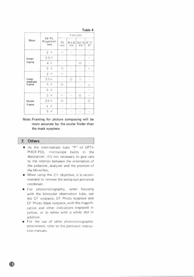
Table 4Film size
CF PLMask Projection356X9 4"X3%"Xlens mmem4%"5"
2 X
X---Inner
2.5X----frame
4 X--©>-
5 X
©>--f::.,2 X
x---Inter-
2.5x-©>f::.,-
mediate frame4 X©>.--f::.,
5 X
----2 X
X-©>-Outer
2.5X©>--©>
frame4 X
-.---5 X
----
Note: Framing for picture composing will bemore accurate by the ocular finder thanthe mask eyepiece.
7. Others• As the intermediate tube "P" of OPTI-
PHOT-POL microscope builts in thedepolarizer, it's not necessary to give careto the relation between the orientation ofthe polarizer, analyzer and the position ofthe Microflex.
• When using the 2 X objective, it is recom-mended to remove the swing-out achromatcondenser.
• For photomicrography, when focusingwith the binocular observation tube, usethe CF eyepiece, CF Photo eyepiece andCF Photo Mask eyepiece, with the magnifi-cation and other indications engraved inyellow, or in white with a white dot inaddition.
• For the use of other photomicrographicattachments refer to the pertinent instruc-tion manuals.
VI. ACCESSORIES
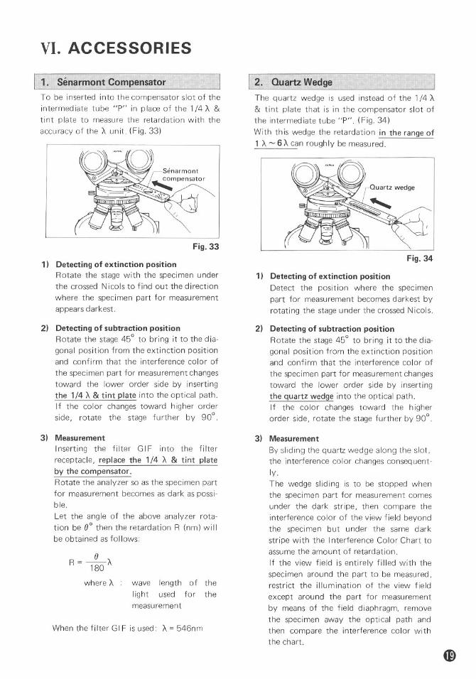
1. Senarmont CompensatorTo be inserted into the compensator slot of theintermediate tube "P" in place of the 1/4 A &tint plate to measure the retardation with theaccuracy of the A unit. (Fig. 33)
Fig. 33
1) Detecting of extinction positionRotate the stage with the specimen underthe crossed Nicols to find out the directionwhere the specimen part for measurementappears darkest.
2) Detecting of subtraction positionRotate the stage 45° to bring it to the dia-gonal position from the extinction positionand confirm that the interference color ofthe specimen part for measurement changestoward the lower order side by insertingthe 1/4 A & tint plate into the optical path.If the color changes toward higher orderside, rotate the stage further by 90°.
2. Quartz WedgeThe quartz wedge is used instead of the 1/4 A& tint plate that is in the compensator slot ofthe intermediate tube "P". (Fig. 34)With this wedge the retardation in the range of1 A ~ 6 A can roughly be measured.
-"~Fig. 34
1) Detecting of extinction positionDetect the position where the specimenpart for measurement becomes darkest byrotating the stage under the crossed Nicols.
2) Detecting of subtraction positionRotate the stage 45° to bring it to the dia-gonal position from the extinction positionand confirm that the interference color ofthe specimen part for measurement changestoward the lower order side by insertingthe quartz wedge into the optical path.If the color changes toward the higherorder side, rotate the stage further by 900
When the fi Iter GIF is used: A = 546nm
3) MeasurementInserting the filter GIF into the filterreceptacle, replace the 1/4 A & tint plateby the compensator.Rotate the analyzer so as the specimen partfor measurement becomes as dark as possi-ble.Let the angle of the above analyzer rota-tion be eO then the retardation R (nm) willbe obtained as follows:
where A wave length of theIight used for themeasurement
3) MeasurementBy sliding the quartz wedge along the slot,the interference color changes consequent-ly.The wedge sliding is to be stopped whenthe specimen part for measurement comesunder the dark stripe, then compare theinterference color of the view field beyondthe specimen but under the same darkstripe with the Interference Color Chart toassume the amount of retardation.If the view field is entirely filled with thespeci men arou nd the part to be measured,restrict the illumination of the view fieldexcept around the part for measurementby means of the field diaphragm, removethe specimen away the optical path andthen compare the interference color withthe chart.
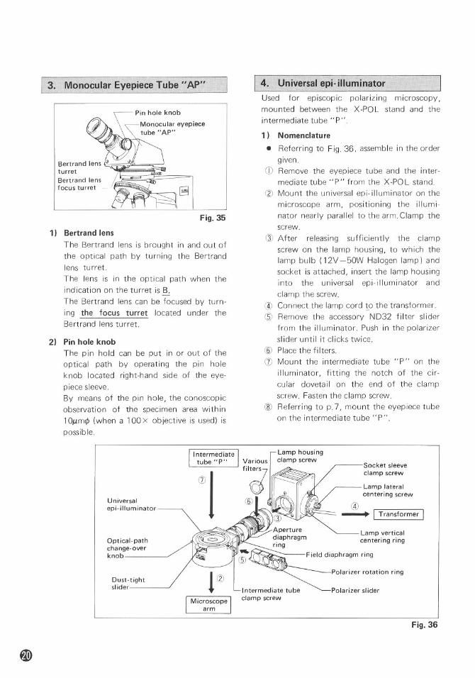
I 3. Monocu,l,ar Eyepiece Tube II AP"
Bertrand lens I~turretBertrand lensfocus turret ~.
Fig. 35
1) Bertrand lensThe Bertrand lens is brought in and out ofthe optical path by turning the Bertrandlens turret.The lens is in the optical path when theindication on the turret is B.The Bertrand lens can be focused by turn-ing the focus turret located under theBertrand lens turret.
2) Pin hole knobThe pin hold can be put in or out of theoptical path by operating the pin holeknob located right-hand side of the eye-piece sleeve.By means of the pin hole, the conoscopicobservation of the specimen area with in10Mm¢ (when a 100 X objective is used) ispossib Ie.
4. Universal epi- illuminatorUsed for episcopic polarizing microscopy,mou nted between the X -POL stand and theintermediate tube "P".
1) Nomenclature
• Referring to Fig. 36, assemble in the ordergiven.
CD Remove the eyepiece tube and the inter-mediate tube "P" from the X-POL stand.
(2) Mount the universal epi-illuminator on themicroscope arm, positioning the illumi-nator nearly parallel to the arm. Clamp thescrew.
QJ After releasing sufficiently the clampscrew on the lamp housing, to which thelamp bulb (12V -50W Halogen lamp) andsocket is attached, insert the lamp housinginto the universal epi-illuminator andclamp the screw.
@ Connect the lamp cord to the transformer.® Remove the accessory ND32 filter slider
from the illuminator. Push in the polarizerslider until it clicks twice.
(§) Place the filters.(J) Mount the intermediate tube "P" on the
illuminator, fitting the notch of the cir-cular dovetail on the end of the clampscrew. Fasten the clamp screw.
® Referring to p.7, mount the eyepiece tubeon the intermediate tube "P".
Universalepi-illuminator
Optical-pathchange-overknob
Dust-tightslider Intermediate tube
clamp screw
Socket sleeveclamp screw
Lamp lateralcenteri ng screw
@--+ I Transformer I
Lamp verticalcentering ring
Field diaphragm ring
Polarizer rotation ring
Polarizer sl ider
Fig. 36
Bottomhemispheri-cal lens
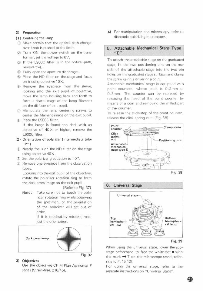
Fig. 38
Point-----
~~~:t~r 0~ Clamp screwspring , L~Lnut ~I Positioning pins
Attachable Imechanical I' ' Istage type E I ,I
~o Cgy~
4) For manipulation and microscopy, refer todiascopic polarizing microscopy.
To attach the attachable stage on the graduatedstage, fit the two positioning pins on the rearside of the attachable stage into the two pinholes on the graduated stage surface, and clampthe screw using a driver or a coin.Attachable mechanical stage is equipped withpoint counters, whose pitch is O.2mm orO.3mm. The counter can be replaced byreleasing the head of the point counter bymeans of a coin and removing the milled partof the counter.To release the click-stop of the point counter,release the click spring nut. (Fig. 38)
5. Attachable Mechanical Stage Type
Fig. 39
When using the universal stage, lower the sub-stage beforehand to face the wh ite dot. withthe mark ~ T on the microscope stand, refer-ring to P. 15 12).For using the universal stage, refer to theseparate instructions on "Universal Stage".
I 6. Universal Stage
Fig. 37
3) ObjectivesUse the objectives CF M Plan Achromat Pseries (Strain-free, 210/45).
Dark cross image
2) Preparation
(1) Centering the lampCD Make certain that the optical- path change-
over knob is pushed to the limit.~ Turn ON the power switch on the trans-
former, set the voltage to 6V.Q) If the L900C filter is in the optical-path,
remove this.@ Fully open the aperture diaphragm.(5) Place the ND filter on the stage and focus
on it using objective 10 X.® Remove the eyepiece from the sleeve,
looking into the exit pupil of objective,move the lamp housing back and forth toform a sharp image of the lamp filamenton the diffuser of exit pupil.
(J) Manipulate the lamp centering screws tocenter the filament image on the exit pupil.
® Place the L900C filter.If the image is found too dark with anobjective of 40 X or higher, remove theL900C filter.
(2) Orientation of polarizer (intermediate tube"P" )
CD Nearly focus on the ND filter on the stageusing objective 40X.
~ Set the polarizer graduation to "0 ".Q) Remove one eyepiece from the observation
tubes.Looking into the exit pupil of the objective,rotate the polarizer rotation ring to formthe dark cross image on the exit pupil.
(Refer to Fig. 37)Note: Take care not to touch the pola-
rizer rotation ring while observingthe specimen, or the orientationof the polarizer will get out oforder.If it is touched by mistake, read-just the orientation.

VII. TROUBLE SHOOTING TABLE
Although nowhere you can find any disorder or derangement in the instrument, if youencounter some difficulty or dissatisfaction, recheck the use, referring to the table below:
1. Optical
Failures Causes,Actions
Darkness at the
• Optical path in trinocular tube' Changing-over to the limitperiphery or
not fully changed-over (Refer to P. 9)
uneven bright-• Centering nosepiece not in click-)Revolve it to click-stop position
ness of view-stop position (Objective not
fieldcentered in optical path)
(No appearance• Lamp bulb not centered ) Centering (Refer to P. 8)
of viewfiedl)
• Condenser not centered ) Centering by using fielddiaphragm (Refer to P. 10)• Field diaphragm too much closed
' Open it properly• Dirt or dust on the lens
Cleaning(Condenser, objective, eyepiece, slide) • Improper use of condenser
' Correct use (Refer to P. 11)• Diffuser not set in or incorrectly
) Correct positioningpositioned
(Refer to P. 8)• Revolving nosepiece not correctly
) Correct attaching (Referto P. 6)attached • Bertrand lens in the optical path
)Flip out (Refer to P. 13 & 19)
• Pin hole in the optical path) Swing out (Refer to P. 19)
(in monocular eyepiece tube "AP") • Top lens of condenser incorrectly, Swing in to the limit
positioned • 1/4 A & tint plate, compensator or' Correct setting
quartz wedge incorrectly positionedDirt or dust in
• Dirt or dust on the lens ) Cleaningthe viewfield
(Condenser, objective, eyepiece, field lens)• Dirt or dust on the slide
) Cleaning• Too low position of condenser
) Correct positioning(Refer to P. 10)
No good image
• No coverglass attached to slide) Correct use (Refer to P. 13)
obtained (lowor NCG objective used with coverglass
resolution or• Too thick or thin coverglass)Use specified thickness (0.17mm)
contrast)
coverglass (Refer to P. 13)• Immersion oil soils the top of dry
) Cleaningsystem objective (especially 40x) • Dirt or dust on the lens (condenser,---> Cleaningobjective, eyepiece, slide)• No immersion oil used on immersion----+ Use immersion oilsystem objective
(Refer to P. 13)• Air bubbles in immersion oil
) Remove bubbles
• Not specified immersion oil used
) Use Nikon immersion oil
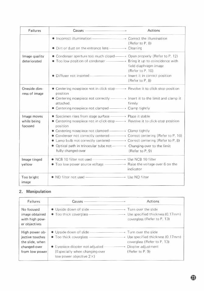
Failures Causes,Actions
• Incorrect illumination
) Correct the illumination(Refer to P. 8)• Dirt or dust on the entrance lens
) Cleaning
Image quality
• Condenser aperture too much c1osed--- Open properly (Refer to P. 12)deteriorated
• Too low position of condenser) Bring it up to coincidence withfield diaphragm image(RefertoP.lO)• Diffuser not inserted
' Insert it in correct position(Refer to P. 8)
Oneside dim-
• Centering nosepiece not in click-stop------> Revolve it to click-stop position
ness of image
position• Centering nosepiece not correctly
)Insert it to the limit and clamp it
attached.firmly
• Centering nosepiece not clamped) Clamp tightly
Image moves
• Specimen rises from stage surface) Place it stable
while being
• Centering nosepiece not in c1ick-stop--> Revolve it to click-stop positionfocused
position• Centering nosepiece not clamped
) Clamp tightly• Condenser not correctly centered
) Correct centering (Refer to P. 10)
• Lamp bu Ib not correctly centered
) Correct centering (Refer to P. 8)
• Optical path in trinocular tube not
,Changing-over to the limit
fully changed-over(Refer to P. 9)
Image tinged
• NCB 10 filter not used ) Use NCB 10 fi Iter
yellow
• Too low power somce voltage) Raise the voltage over 6 on theindicator
Too bright
• ND fi Iter not used ) Use ND filter
image
2. Manipulation
Failures Causes)Actions
No focused
• Upside down of slide ) Turn over the slide
image obtained
• Too thick coverglass )Use specified thickness (O.17mm)
with high pow-
coverglass (Refer· to P. 13)
er objectives High power ob-
• Upside down of slide ) Turn over the slide
jective touches
• Too thick coverglass ) Use specified thickness (O.17mm)
the slide, when
coverglass (Refer to P. 13)
changed-over
• Eyepiece diopter not adjusted) Diopter adjustmentfrom low power
(Especially when changing-over(Refer to P. 9)low power objective 2·X)
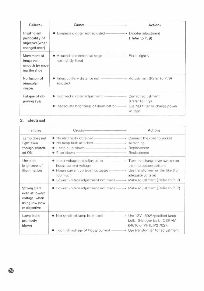
Failures Causes,Actions
Insufficient
• Eyepiece diopter not adjusted) Diopter adjustmentparfocality of
(Refer to P. 9)objective(when changed-over)
Movement of
• Attachable mechanical stage,Fix it tightly
image notnot tightly fixed
smooth by mov- ing the slideNo fusion of
• Interpupi Ilary distance not, Adjustment (Refer to P. 9)binocular
adjustedimages
Fatigue of ob-
• Incorrect diopter adjustment) Correct adjustmentserving eyes
(Refer to P. 9)• Inadequate brightness of illumination -----> Use ND filter or change power voltage
3. Electrical
Failures Causes,Actions
Lamp does not
• No electricity obtained ) Connect the cord to socketlight even
• No lamp bulb attached ' Attachingthough switch-
• Lamp bulb blown )Replacemented ON
• Fuse blown ,Replacement
Unstable
• Input voltage not adjusted to) Turn the change-over switch onbrightness of
house current voltage the microscope bottomillumination
• House current voltage fluctuates,Use transformer or the like (fortoo much
adequate voltage)• Lowest voltage adjustment not made ----> Make adjustment (Refer to P. 7)
Strong glare
• Lowest voltage adjustment not made ----> Make adjustment (Refer to P. 7)even at lowest voltage, whenusing low pow-er objective
Lamp bulb
• Not specified lamp bulb used,Use 12V -50W specified lamp
promptlybulb: (Halogen bulb: OSRAM
blown64610 or PH III PS 7027)
• Too high voltage of house current
,Use transformer for adjustment

Failures Causes,Actions
Insufficient
• Lamp bulb not centered , Centering (Refer to P. 8)brightness of
• Condenser not centered , Centering (Refer to P. 10)illumination
• Condenser aperture too much closed -- Open it properly (Refer to P. 12)• Too low position of condenser
' Correct positioning(Refer to P. 10)• Not specified lamp bulb used
• Use 12V-50W specified Halogenbulb• Dirt on lens (condenser, objective,
' Cleaningeyepiece, field lens, filter) • Too low voltage
,Raise the voltage
Fuse blown
• Not specified fuse used , Use 1A/250V or O.75A/250V
Flickering or
• Lamp bulb going to be blown., Replacement
unstable• Connector not connected securely, Secure connection
brightness of• Fuse holder not firmly fastenedFirm fastening
lamp bulb• Irregular change of house currentUse stabilizer
voltage • Lamp bulb insufficiently inserted• Positive connection
into the socket
REFERENCE
This manual instructs only how to manipulate the OPTIPHOT-POL microSCDpe.
For the practical explanation on polarizing microscopy, referto the following special works:
• "AN INTRODUCTION TO THE METHODS OF OPTICALCRYSTALLOGRAPHY"
- F. Donald BlossHolt, Rinehart and Winston
• "ORE MICROSCOPY"
- Eugene N. CameronJohn Wiley & Sons. Inc.
• "THE POLARIZING MICROSCOPE"
- F.A. Hallimond -Vickers Instruments
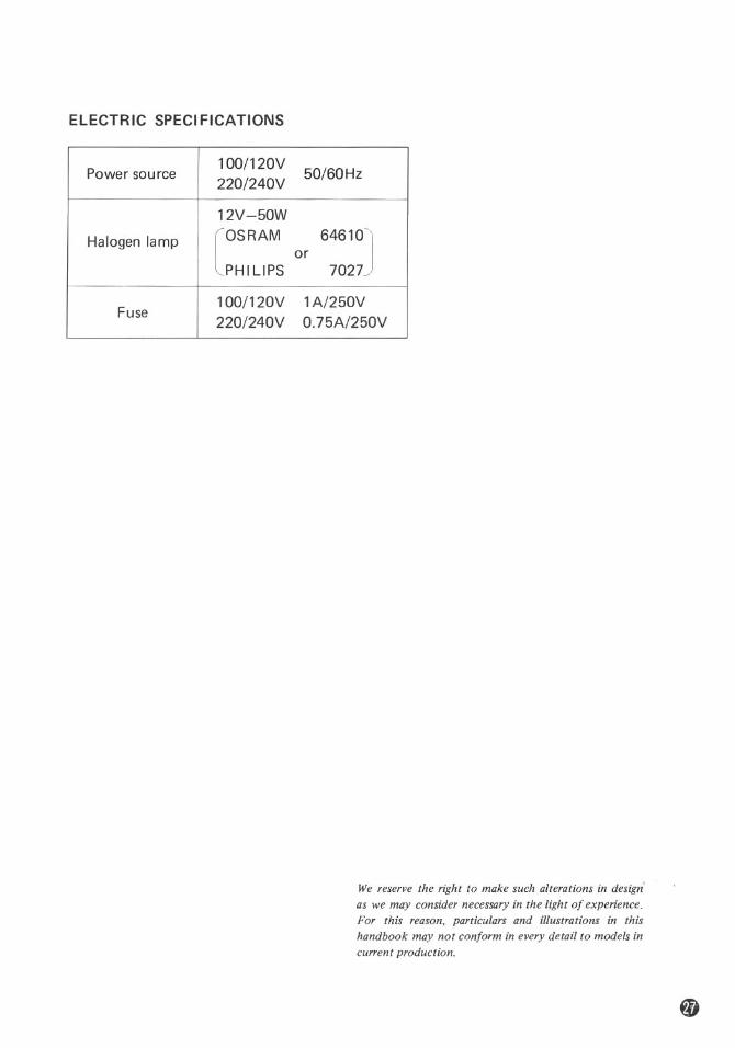
ELECTRIC SPECIFICATIONS
Power source100/120V
50/60Hz220/240V12V-50WHalogen lamp [OSRAM 64610JPH III PS or 7027
Fuse
100/120V1A/250V
220/240V0.75A/250V
We reserve the right to make such alterations in design'as we may consider necessary in the light of experience.For this reason, particulars and illustrations in thishandbook may not conform in every detail to models incurrent production.

(Nikon)NIPPON KOGAKU K.K.Fuji Bldg., 2-3, 3 chome, Marunouchi,Chiyoda-ku, Tokyo 100, Japanft03-214-5311Telex: J22601 (NIKON)
Printed in 1apan
:'
(86.4.e)H . E -5r