
PO748300 Bk2of3 - Voice Communications Inc. … · 100-2 Maid Identification Operating parameters...
381
PO748300 Bk2of3
Transcript of PO748300 Bk2of3 - Voice Communications Inc. … · 100-2 Maid Identification Operating parameters...

PO748300Bk2of3

I ssued: 93 10 31Status: StandardXi 1 Release: All
100-l
Maid IdentificationThe Maid Identification, or Maid ID, feature makes it easier to keep track ofwhich maids clean which rooms. Maid ID introduces a new keyword, MI, anda I- to 4-digit Maid ID.
The MT keyword is used with the Background Terminal SEt STatus commandwhen a room’s cleaning status is changed. The Maid ID number, whichaccompanies the MI keyword, uniquely identifies a maid.
The following features allow the Maid ID to be entered as part of the roomcleaning s tatus:
- Background Terminal (BGD) SEt STatus command
- Room Key (RMK) Operation
- Dial Access method
- Off-hook Detection
- Controlled Class of Service (CCOS) key operation
Note: For Off-hook Detection and CCOS key operation, the Maid IDalways defaults to zero.
Feature interactionsMaid ID alters dial access for Room Status (RMS). After entering a validcleaning status, instead of hearing dial tone or Flexible Feature Code (FFC)confirmation tone, the maid hears a special interrupted dial tone, prompting Ifor the Maid ID. The Maid can then enter the Maid ID followed by theoctothorpe (#), or can hang up.
Xi I features and services 553-3001-305
:.:

100-2 Maid Identification
Operating parametersMeridian Modular Terminal firmware, version 11, and the Hospitality ScreenEnhancement (HSE), package (208), are needed to support the special MaidID screens. They are not required to support the feature itself.
For Off-hook Detection, Line Lockout (LLT) must be defined as overflowtone in LD15. Any other lockout definition prohibits Maid ID use withOff-hook Detection, see the Xl I input/output guide (553-3001-400).
Feature packagingMaid Identification (MAID), package 210, requires
- Maid Identification (MAID), package 210
- Background Terminal (BGD), package 99
- Room Status (RMS), package 100
- Controlled Class of Service (CCOS), package 81
Optional packages include
- Property Management System (PMS), package 103
- Flexible Feature Codes (FFC), package 139
- Hospitality Screen Enhancements (HSE), package 208
Feature implementationMaid ID does not require any additional service change implementation. Ifthe feature package is equipped, implement Maid ID using a BackgroundTerminal (BGD) or Property Management System Interface (PMSI). SeeBackground Terminal Facility description (553-2311-316) and PropertyManagement System Integace description (553-2801-101). See also “RoomStatus,” in this document, for information regarding its implementation.
Feature operationMaid ID can be entered along with room cleaning status in the BackgroundTerminal (BGD) or Property Management System (PMS). For a completediscussion of this feature’s programming, see Background Terminal Faci l i tydescription (553-2311-316) and Property Management System Interfacedescription (553-2801-101).
Xl 1 features and services 553-3001-305

Maid Identification 100-3
Room key operationThe steps for the Room key (RMK) operation are:
1 Press RMK once. The indicator flashes.
2 Dial the Directory Number (DN) of the room for which the cleaningstatus is being changed. The indicator l ights s teadi ly.
3 Enter a cleaning status code, 1 through 71 = cleaning requested2 = cleaning in progress3 = room cleaned4 = room passed inspect ion5 = room failed inspection6 = cleaning skipped7 = not for sale
4 Press the asterisk (*). This sets the display to accept the Maid ID. Theasterisk does not show on the display. Each time the asterisk (*) isentered, the display clears.
When Hospitality Screen Enhancements (HSE) is equipped, andMeridian Modular telephones are used with firmware version 11 orhigher, the display looks like this:
xxx...x Enter Maid ID
xxx...x = Room DN
5 Enter the Maid ID.
With HSE, a cursor marks the beginning position for the Maid ID. TheMaid ID shows on the display. Correct the Maid ID by pressing theasterisk (*) to clear the incorrect Maid ID and to reset the display. Enterthe correct Maid ID.
6 Press RMK again to complete the operation. The RMK indicator goesoff.
Xl 1 features and services 553-3001-305
.: ~: :

100-4 Maid Identification
Dial Access methodThis method uses either Special Prefix (SPRE) codes or Flexible FeatureCodes (FFCs).
Special Prefix (SPRE)To enter Room Status (RMS) using SPRE codes:
1 Lif t the handset .
2 D i a l SPRE+86.
3 Enter a cleaning status code, 1 through 7 as fol lows.1 = cleaning requested2 = cleaning in progress3 = room cleaned4 = room passed inspect ion5 = room failed inspection6 = cleaning skipped7 = not for saleSpecial interrupted dial tone is heard, prompting for the Maid ID
Operation prior to X11 release 17 used steps 1 through 4, and step 8. Steps 5,6, and 7 have been added with Maid ID. If these new steps are skipped, thesystem sets the Maid ID to zero.
4 Press the asterisk (*). This sets the display to accept the Maid ID. Theaster isk (*) does not show on the display.
5 Enter the Maid ID. The digits are shown on the display, if equipped. Ifyou dial an incorrect Maid ID, press the asterisk (*), and reenter the MaidID.
6 Press the octothorpe (#) to end Maid ID entry. The octothorpe (#) doesnot appear on the display.
7 Hang up the handset .
Xl 1 features and services 553-3001-305

Maid Identification 100-5
Flexible Feature Codes (FFCs)To enter Room Status using Flexible Feature Codes:
1 Lif t the handset .
2 Enter the RMST FCC.
3 Enter a cleaning status code, 1 through 7 as follows:1 = cleaning requested2 = cleaning in progress3 = room cleaned4 = room passed inspect ion5 = room failed inspection6 = cleaning skipped7 = not for sale
Operation prior to xl1 release 17 used steps 1 through 3 and steps 7a and b.Steps 4,5 and 6 have been added with Maid ID. A special interrupted dialtone prompts for the Maid ID number. If these new steps are skipped, thesystem sets the Maid ID to zero. Hang up or press RLS.
4 Press the asterisk (*). This sets the display to accept the Maid ID; i t doesnot show on the display.
5 Enter the Maid ID. The digits appear on the display. If you enter anincorrect Maid ID, press the asterisk (*), and reenter the Maid ID.
6 Press the octothorpe (#) to end Maid ID entry. The octothorpe (#) doesnot appear on the display.
7 a If the FCC confirmation tone was configured, you hear the FCC
confirmation tone. Hang up or press RLS.
7b If the FCC confirmation tone was not configured, you will hear a dial
tone. Make a call, hang up, or press RLS.
Xl 1 features and services 553-3001-305
-.
100-6 Maid Identification
Xl 1 features and services 553-3001-305
:,
; , - . .

101-I
Make Set BusyThe Make Set Busy (MSB) feature allows an SL-1 or Meridian digitaltelephone to appear busy to all incoming calls. Outgoing calls can still bemade from the telephone. To activate this feature, a separate MSB key/lamppair must be assigned. Incoming calls to Multiple Appearance DirectoryNumbers (MADNs) in the MSB mode are still signified by the indicator nextto the Directory Number (DN) key, and can be answered even while MSB isactive. Calls to any Single Appearance Directory Number on the telephonereceive a busy indication. MSB does not affect incoming Private Line calls.
Operating parametersMSB does not apply to 500/2.500 telephones.
Feature interactions- Call Forward All Calls
Call Forward All Calls and then Hunting take precedence over MSB.
- Voice CallVoice Call is blocked by MSB.
- Automatic Call DistributionSee Automat ic Cal l Dis tr ibut ion basic features descr ipt ion(553-267 I- 100) for information on MSB operations.
Feature packagingMSB, package 17, has no feature package dependencies.
Xl 1 features and services 553-3001-305

101-2 Make Set Busy
Feature implementation
LDll -Add or change MSB for SL-1 and Meridian digital telephones.
R E Q
T Y P E
T N
K E Y
C H G
aaaa
l s c u
xx MSB
Change
Te lephone type
aaaa = SLl, 2006,2008,2009,2016,2018,2112,2216,2317, 2616, 3000
Termina l Number (TN)
Add a MSB key (must be key 30 for M3000 telephones)
xx = key number
Feature operationTo make a telephone appear busy to callers
- Without l i f t ing the handset , press the MSB key. The indicator l ightssteadily and the telephone will not receive calls.
To cancel MSB
- Without l i f t ing the handset , press the MSB key.
Xi 1 features and services 553-3001-305
_.,. .‘, -;. ..:. ‘, .; ,:. ., . . . . ..: , : .:

Malicious Call TraceMalicious Call Trace (MCT) al lows users of selected telephones to act ivate acall trace that results in a printed report of the calling and called parties. Thereport is generated on all system TTYs designated as maintenance (MTC)terminals.
Malicious Call Trace (MCT) is activated either by dial access fromsingle-l ine, SL- 1 and Meridian digi tal telephones, or by key access from SL- 1telephones, Meridian digi tal telephones, and at tendant consoles.
If the initiator hears overflow tone, the call trace has failed for one of thefollowing reasons:
- The station does not have Malicious Call Trace Allowed (MCTA) classof service (CLS)
- The stat ion is not establ ished on an act ive cal l
- The system could not al locate a print register to store the traceinformation
An attendant can activate Malicious Call Trace (MCT) only from an attendantconsole by using the Trace (TRC) feature key. When the Trace (TRC) key ispressed, the system prints a trace report on the source party, the destinationparty, or both, depending on whether the source key, the destination key, orboth keys are active. The printing of the MCT record is preceded by a bellsound on the maintenance TTY. In the printout , only the console’s primaryTerminal Number (TN) is reflected in the TN field.
The MCT record identif ies the source or dest inat ion (or both) by print ing S orD (or both) prior to the time and date stamp of the record.
Xl 1 features and services 553-3001-305

102-2 Malicious Call Trace
Operating parametersThe MCT feature is implemented on a system basis.
Assignment of the Trace (TRC) key cannot be done through the AttendantAdministration feature.
The MCT feature is not available on Automatic Call Distribution (ACD)telephones.
The TRC key cannot be assigned as a softkey on Meridian digi ta l te lephones.
Feature interactions- Conference call
When a stat ion or console that is on the conference loop activates theMCT feature, the trace record shows only the conference loop numberand conference number as the ORIGTN, and the Terminal Number (TN)of the station or console that activated the feature as the TERTN. Noinformation on the other parties in the conference is given.
- History FileThe MCT records are stored in the History File if it has been defined asa maintenance (MTC) user in LD17.
- Traffic MeasurementThe MCT feature is added to the feature key list for traffic measurements(Peg Count TFCOOS).
Feature packagingMalicious Call Trace (MCT), package 107, has no feature packagedependencies.
Xl 1 features and services 553-3001-305

Malicious Call Trace 102-3
Feature implementation
LDlO - Add or change Malicious Call Trace for 500/2500 telephones.
R E Q C H G Change
TYPE 500 Telephone type
T N l s c u Termina l Number
CLS MCTA, (MCTD) MCT allowed or denied
XFA, (XFD) Call Transfer allowed or denied
Note: When MCTA is assigned, the telephone must also have XFA defined.
R E Q C H G
TYPE aaaa
T N l s c u
C L S MCTA, (MCTD)
K E Y xx TRC
LDll -Add or change Malicious Call Trace for SL-1 and Meridian digital telephones.
Change
Te lephone type
aaaa = SLI, 2006,2008,2009,2016,2018,2112,2216,2317,2616,3000
Termina l Number
MCT allowed or denied
MCT key (LED not required)
xx = key number
Note: When MCTD is assigned, the MCT key is removed.
LD12 - Add or change Malicious Call Trace for at tendant consoles.
R E Q
TYPE
T N
KEY
C H G
ATT, 1250,225O
l s c u
xx TRC
Change
Conso le t ype
Termina l Number
MCT key
xx = O-9 (QCW and M1250)
xx = O-l 9 (M2250)
Xi 1 features and services 553-3001-305
102-4 Malicious Call Trace
Feature operationTo trace a malicious call from a 500/2500 telephone:
1 Flash the switchhook or press Link. A special dial tone s ignif ies that thecall is on hold.
2 Enter SPRE+83. You are connected to the call.
To trace a malicious call from an SL-1 or Meridian digital telephone usingSpecial Prefix (SPRE) code:
1 Press Transfer or Conference. A special dial tone signifies that the calli s on ho ld .
2 Enter SPRE+83. You are connected to the call.
To trace a malicious cal l from an SL-1 or Meridian digital telephone using theTrace (TRC) key:
1 Press Call Trace. You remain connected to the call.
Xi 1 features and services 553-3001-305

Issued: 92 1231Status: StandardXl 1 Release: Al l
Manual Line Service103-l
Manual Line Service allows all calls made from 500/2500 telephones definedas manual telephones to be handled automatically by an at tendant. When thecaller goes offhook, the attendant is contacted immediately. Calls can beplaced to telephones with Manual Line Service.
Operating parametersManual Line Service applies only to 500/2500 telephones.
Feature interactions- Attendant Alternative Answering (AAA)
When AAA is defined, Manual Line service follows the AAAparameters.
- Attendant Overflow Position (AOP)When AOP is defined, Manual Line service follows the AOP directions.
- Night Service (NSVC)When the system is in NSVC mode, all telephones with a manual classof service (CLS) are routed to the telephone designated as the nightnumber for the customer group.
Feature packagingThis capability is included in basic Xl 1 system software.
Xi 1 features and services 553-3001-305

103-2 Manua l L ine Serv ice
Feature implementation
LDlO - Define class of service (CLS) for Manual Line telephones.
R E Q C H G
TYPE 5 0 0
T N l s c u
D N xxx...x
CLS M N L
Change
Te lephone type
Termina l Number (TN)
Directory Number (DN) assigned to the telephone
Arrange telephone for manual service
Feature operationTo use Manual Line Service from a 500/2500 telephone, l if t the handset . Youare automatically connected to the at tendant.
Xi 1 features and services 553-3001-305
i ssued: 92 1231Status: StandardXi 1 Release: Al l
Manual Signaling (Buzz)104-l
Manual Signaling (Buzz) permits an SL-1 or Meridian digital telephone userto sound a buzztone at a specific telephone. The Meridian M3000Touchphone provides the buzzing capabil i ty by means of an Active Statescreen softkey.
To activate this feature, a separate buzz key must be equipped. An associatedlamp or indicator is not required, however.
The buzz tone continues as long as the key remains depressed. ManualSignaling (Buzz) has no impact on an exist ing cal l or on other act ive features.If the other telephone is busy on a call, it will still buzz, even if it is aHandsfree call.
Operating parametersManual Signal ing (Buzz) does not apply to 500/2500 te lephones . Only SingleAppearance Directory Numbers can be buzzed.
Feature interactionsNot applicable.
Feature packagingManual Signaling (Buzz) is included in basic Xl 1 system software.
Xl 1 features and services 553-3001-305

104-2 Manual S igna l ing (Buzz)
Feature implementation
LDll -Add or change Manual Signaling (Buzz) for SL-1 and digital telephones.
R E Q C H G
TYPE aaaa
Change
Te lephone type
aaaa = SLI ,2006,2008,2009,2016,2018,2112,2216,2317, 2616, 3000
T N
KEY
l s c u
xx SIG yyy...y
Termina l Number (TN)
Add a Manual Signaling (Buzz) key
xx = key number
yyy...y = DN to be buzzed (must be a Single AppearanceD i rec to ry Number
Feature operationTo buzz a specific telephone:
- Press Buzz. The other telephone emits a buzz sound from the speaker foras long as you hold down the Buzz key.
Xl 1 features and services 553-3001-305
.,

Manual Trunk ServiceManual outgoing trunk service permits you to complete an outgoing cal l , af terringing the trunk, by dialing a predefined trunk access code. Manualincoming trunks, when seized at the far end, are automatically terminated ona specified Directory Number (DN) or, if no DN is specified, at the attendant.
Manual Trunk Service is defined by the trunk class of service (CLS), and canbe applied to outgoing, incoming, and outgoing/incoming trunks. This featureis available to the central office (CO), FX, WATS, and tie trunks with animmediate start arrangement.
Operating parametersManual incoming service can be applied to tie trunks only.
Feature interactions
Feature packagingThis capability is included in basic Xl 1 system software.
Xl 1 features and services 553-3001-305

105-2 Manua l T runk Serv i ce
Feature implementation
LD16 - Add or change an incoming manual trunk route.
R E Q
TYPE
CUST
R O U T
T K T P
ICOG
ACOD
N E W , C H G
R D B
o-99
o-51 1
TIE
I C T
XxXx x
Create a new route or modify an existing one
Route Data Block
Cus tomer number
Route number
Incoming manual trunks (must be tie trunks)
Incoming rou te
Trunk route access code
LD14 - Add or change an incoming manual trunk.
R E Q
TYPE
T N
CUST
R T M B
M N D N
SIGL
STRI
SUPN
CLS
N E W , C H G
T I E
l s c u
xx
rrr mmm
xxx...x
a a a
IMM
Yes, (No)
MIA, (MID)
Create a new trunk or modify an existing one
Tie trunks are required for manual incoming trunks
Termina l number (TN)
Cus tomer number
Route and member number
Directory Number (DN) for automatically terminate
Trunk s igna l ing
aaa = DX2, DX4, EAM, EM4, GRD, LDR, LOP, OAD
Incoming s ta r t a r rangement
Answer and disconnect supervision required or not required
Manual incoming service allowed or denied
Xi 1 features and services 553-3001-305
. .

Manua l T runk Serv i ce 105-3
LD16 - Add or change an outgoing manual trunk route.
R E Q
TYPE
CUST
R O U T
TKTP
ICOG
ACOD
MAN0
N E W , C H G
R D B
o-99
o-51 1
aaa
OGT
xxxx . . x
Yes
Create a new route or modify an existing one
Route Data Block
Cus tomer number
Route number
Outgo ing t runk type
aaa = ADM, AID, ATVN, AWR, CAA, CAM, COT, CSA, DIC, DID,FEX, ISA, ISL, MDM, MUS, PAG, RAN, RCD, RLM, RLR,TIE,WAT
Outgo ing rou te
Trunk route access code
Enable manual outgoing trunk route
LD14 .- Add or change an outgoing manual t runk.
R E Q
TYPE
T N
CUST
R T M B
M N D N
SIGL
N E W , C H G
T I E
l s c u
xx
rrr mmm
xxx...x
aaa
Create a new trunk or modify an existing one
Tie trunks are required for manual incoming trunks
Termina l number (TN)
Cus tomer number
Route and member number
Directory Number (DN) for automatically terminate
Trunk s igna l ing
aaa = DX2, DX4, EAM, EM4, GRD, LDR, LOP, OAD
Feature operationNot applicable.
Xi 1 features and services 553-3001-305

105-4 Manua l T runk Serv i ce
Xi 1 features and services 553-3001-305

Issued: 92 1231Status: StandardXi 1 Release: 16
106-l
Meridian Hospitality Voice ServicesMeridian Hospitality Voice Services (MHVS) links Meridian Mail GuestVoice Messaging with the Property Management System (PMS) and theMeridian 1. Meridian Mail uses information from the Property ManagementSystem Interface (PMSI) to manage guest voice messaging and to coordinatethe Message Wait ing indicat ions for both voice and text messaging.
Meridian Hospitality Voice Services (MHVS) allows Meridian Mail tointercept messages sent over the Property Management System Interface(PMSI) and to pass the Meridian 1 only those messages required to manageand coordinate message indications for both voice and text messages. ShouldMeridian Mail ever fail, a Meridian Mail bypass switch allows the Meridian1 to be directly connected to the Property Management System Interface(PMSI).
Meridian Hospitality Voice Services (MHVS) provides enhancements to thefollowing features:
- Pretranslation MHVS will suppress all pretranslation on callsoriginated by Meridian Mail virtual agents.
- Do Not Disturb MHVS allows calls to telephones in a Do Not Disturb(DND) mode to be rerouted to Meridian Mail for special handling.
- Controlled Class of Service (CCOS) When CCOS is allowed onM2327 and M3000 telephones, they do not display the softkey choicesfor standard Meridian Mail features that do not apply when thesetelephones are used in guest rooms. Dial Access is required to activatethese features.
Xl 1 features and services 553-3001-305
:- .

106-2 Meridian Hospitality Voice Services
New Property Management System (PMS) messages (from X11 release 16)are used to integrate the link. Meridian HVS allows Meridian Mail tointercept messages over the Property Management System Interface (PMSI)and passes to the Meridian 1 only those messages required. Should MeridianMail ever fail, a bypass switch allows the Meridian 1 to link directly with theProperty Management System (PMS).
operaiing parametersThe Night Number (NCWF) specified for the AP Recovery enhancementmust be local to the system. It cannot be defined using Network AutomaticCall Distribution (Network ACD) routing tables.
Attendant consoles cannot be associated with mailboxes on Meridian Mail .
Softkey menus are suppressed for Meridian HVS commands on M2317 andM3000 telephones when Controlled Class of Service (CCOS) has beenactivated. Dial access must be used to operate Meridian HVS features, exceptguest messaging mailboxes.
When programming the Night Directory Number (Night DN) associated withthe customer and Automatic Call Distr ibution (ACD) queues, be sure to avoidconfiguring a loopback of Directory Numbers (DNs) for the Night CallForward DN. For example, if the Night Call Forward DN terminates on aconsole (direct ly or indirect ly) , then the at tendant Night DN should notterminate on the Meridian Mail virtual ACD DN. With this configuration,calls will remain ringing in the ACD queue under these conditions:
- The system is in Night Service Mode
- Meridian Mail fails
The caller remains in the queue unti l the at tendant disengages Night Service,or until the Applications Module Link (AML) recovers from failure.
The use of Integrated Messaging System (IMS) or Integrated VoiceMessaging System (IVMS) is not supported with Meridian HVS.
Xi 1 features and services 553-3001-305

Meridian Hospitality Voice Services 106-3
Feature interactions- Attendant End to End Signaling (EES)
Attendant EES (which uses Dual Tone Multifrequency (DTMF)signaling) requires an additional Attendant EES key.
- Attendant Overflow Position (AOP)AOP al lows unanswered cal ls to the at tendant to be forwarded to acustomer-defined Directory Number (DN) after a defined time. A callmay also be overflowed if all the attendants are in Position Busy State.With AOP equipped in Xl 1 release 16, overflowed calls can be directedto Meridian Mail. The AOP DN must be defined as an Automatic CaseDistribution (ACD) Directory Number (DN), and the ACD DN musthave an ACD agent assigned as a vir tual VMS agent.
- Centralized Attendant Service (CAS)The attendant must be located on the same switch as Meridian Mail forthe at tendant to use Meridian Mail features.
- Digit Key Signaling (DKS)DKS is supported only from at tendant consoles at the Meridian Mail s i te .
- Digit Key Signaling (DKS) at consoleWith DKS equipped, attendants may assist callers in Meridian Mailactivities. The attendant may extend source calls to Meridian Mail ordirect calls to Meridian Mail.
- Do Not Disturb (DND)Individual Do Not Disturb (DND) allows the attendant to place aDirectory Number (DN) into DND mode. A DN in this mode is free tooriginate calls, but appears busy to incoming calls. With Meridian HVSequipped, a new prompt (DNDH) allows callers to be redirected toMeridian Mail for voice mail services. A called telephone must haveHunting Allowed (HTA) class of service, and Hunt to Meridian Mail andDNDH in LD1.5 must both be set to YES.
- M2317, M3000, and Meridian Modular softkey menusM2317 or M3000 softkey menus are not supported by Meridian HVS.These telephones with Controlled Class of Service Allowed (CCSA)class of service are not presented with the Meridian Mail softkey menuswhen connected to Meridian Mail .
Xl 1 features and services 553-3001-305
_’

106-4 Meridian Hospitality Voice Services
- Network ACDThe Night Number (NCFW) specified for the ACD must be local to thenode.
- Property Management System Interface (PMSI), Digit Key Signaling(DKS), DNDH, and Message Waiting indicationThese operations are supported only when PMSI, Meridian Mail , andattendant and room telephones are located on the same Meridian 1swi tch .
- PretranslationPrior to Meridian HVS, the setup of cal ls using the Applicat ions ModuleLink (AML) was not supported from telephones using the Pretranslat ionfeature. With HVS equipped, cal l setup using the AML is supported.
- Stripping of Call Party Name Display (CPND) blanksThe maximum length of a CPND name sent from the PMSI/BackgroundTerminal (BGD) is 27 characters. When the full 27-character length isused, part of the CPND name may scroll off the screen. To avoid thisproblem, the PMSI/Background Terminal (BGD) software has beenupdated to strip from the screen all trailing blanks from the CPND name.
Xl 1 features and services 553-3001-305
. . .. ..’ ..:

Feature packaging
Meridian Hospitality Voice Services 1 0 6 - 5
Meridian HVS requires
- Meridian Hospitality Voice Services (HVS), package 179, whichrequires
.
.
.
.
.
.
.
.
.
.
Recorded Announcement (RAN), package 7
End to End Signaling (EES), package 10
Make Set Busy (MSB), package 17
Integrated Messaging System (IMS), package 35
Basic Automatic Call Distribution (BACD), package 40
Automatic Call Distribution Package A (ACDA), package 45
Message Center (MWC), package 46
Command and Status Link (CSL), package 77
CSL with Alpha Signaling (CSLA), package 85
Auxiliary Processor Link (APL), package 109
- Property Management System Interface (PMSI), package 103, whichrequires
. Controlled Class of Service (CCOS), package 81
. Background Terminal (BGD), package 99
. Room Status (RMS), package 100
Attendant Overflow Position (AOP), package 56, is required for AOPDirectory Number (DN) enhancement.
- Digit Key Signaling (DKS), package (180), which requires
. Hospitality Voice Services (HVS), package 179
The site may also require other packages, such as
. Message Registration (MR), package 101
. Automatic Wake Up (AWU), package 102
Xl 1 features and services 553-3001-305

106-6 Meridian Hospitality Voice Services
Feature implementationRefer to Meridian Mail Modular Option Guest Voice Messuging(553-7041-210) and Property Management System Integace descript ion(553-2801-101)
Feature operationRefer to Meridian Mail Modular Option Guest Voice Messaging(553-7041-210) and Proper5 Management System Inte$ace descript ion(553-2801-101)
Xl 1 features and services 553-3001-305
,./’ -. ,,.

Issued:Status:Xi 1 Release:
Meridian MailRelated Documents
For complete information concerning Meridian Mail, see the documents inthe l is ts that fol low.
Meridian Mail OptionsMaster Index (553-7001-000)
General Description (553-7001-100)
Expansion Guide (553-7001-211)
Networking Installation Guide (553-7001-213)
System Options Guide (553-7001-215)
System Administration Guide (553-7001-301)
System Administration Tools (553-7001-305)
Restore and Voice Volume Recovery Guide (553-7001-308)
Maintenance Messages (553-7001-5 10)
Site and Installation Planning (553-701 l-200)
Installation Checklist (553-701 l-205)
Installation Guide (553-701 l-210)
Maintenance Procedures (553-701 l-500)
Xl 1 features and services 553-3001-305

107-2 Meridian Mail
Meridian Mail GPMaster Index (553-7001-000)
General Descr ip t ion (553-7001-100)
Expansion Guide (553-7001-211)
Networking Installation (553-7001-214)
System Administration Guide (553-7001-301)
Sys tem Adminis t ra t ion Tools (553-7001-305)
Maintenance Messages (553-7001-510)
Si te and Ins ta l la t ion Planning (553-7031-200)
Installation Procedures (553-7031-210)
Maintenance Procedures (553-7031-500)
Meridian Mail Modular OptionMaster Index (553-7001-000)
General Descr ipt ion (553-7001-100)
Expansion Guide (553-7001-211)
Networking Ins ta l la t ion Guide (553-7001-213)
System Adminis tra t ion Guide (553-7001-301)
System Administration Tools (553-7001-305)
Maintenance Messages (553-7001-510)
Si te and Ins ta l la t ion Planning (553-7041-200)
Meridian Mail Modular Option Guest Voice Messaging (553-7041-210)
Maintenance Procedures (553-7041-500)
X11 featuresandservices 553-3001-305

108-l
Meridian Mail Voice MailboxAdministration
The Meridian Mail Voice Mailbox Administration (VMBA) feature enablesthe Meridian 1 system administrator to use Meridian 1 administrationoverlays to administer and maintain the Meridian Mail Voice MailboxApplication. This feature streamlines the process of implementing andmaintaining voice mailboxes (VMBs).
VMBA provides the following capabilities:
- Accessing the Voice Mailbox Application via LDs 10 and 11 rather thanvia a separate terminal
- Viewing applicat ion and mailbox stat is t ics to help ensure the integri ty ofthe applicat ion
- Synchronizing the Meridian 1 and Meridian Mail databases using specialaudit and upload funct ions
. The audit function helps ensure that name data stored on theMeridian 1 is synchronized with name data s tored on Meridian Mail .The system administrator can run the audit manually or request thatthe system run it periodically.
. For sites that want to implement VMBA and already have VMBsconfigured on Meridian Mail, the VMBA upload function lets thesystem administrator create or update the Meridian 1 VMB databasefrom the existing Meridian Mail VMB database. Upload cansignificantly reduce the time required to implement VMBA.
Xl 1 features and services 553-3001-305

108-2 Meridian Mail Voice Mailbox Administration
Access to Meridian Mail VMB adminis t rat ion funct ions is s t i l l avai lable withthe Meridian Mail administration console. However, to prevent databaseinconsistencies, use the Meridian 1 for VMB administration when VMBA isequipped.
In X11 release 19, VMBA is supported on RT, XT, NT, and STE systems, aswell as on Options 21A, 21E, 51,61,71, and 81. Telephone types supportedinclude the SL-1, Meridian Modular telephones, M2317, M2000, M3000, and500/2500.
CAUTIONBecause there is a potential impact on the Meridian 1 CPND databasewhen using the VMBA application, users should read with care thesections enti t led “Name processing considerations” on page 108-4 and“Site with a preconfigured Meridian Mail database” on page 108-15.
Operating parametersThe appropriate VMB class of service’ must be defined on Meridian Mailbefore the Meridian 1 can add VMBs. Otherwise, Meridian Mail transactionerrors will occur.
A Meridian 1 supports only one Meridian Mail system for VMBs.
The Meridian 1 allows for only one VAS and one customer to be configuredfor this application.
If a VMB is deleted on the Meridian 1 but not on Meridian Mail, the resultcould be an orphan VMB. If the DN for the deleted VMB is reused on theMeridian 1, Meridian Mail deletes the old DN and adds the new one, therebyrecovering the associated VMB. If the DN is not reused, the orphan VMB isnot recovered.
VMB changes made directly on a Meridian Mail administration terminal maynot be detected for up to five days, because Meridian 1 automatic databaseaudits ( if equipped) can only run every five days.
1. A Meridian Mail class of service specifies a particular set of Meridian Mail options.
Xl 1 features and services 553-3001-305
_ .

Meridian Mail Voice Mailbox Administration 1 0 8 - 3
The VMB s t a t u s printed in LD20 indicates the s tatus of t ransact ions on theMeridian 1, not on Meridian Mail. For example, if a VMB is disabled onMeridian Mail , i ts s ta te is not updated on the Meridian 1.
VMBs cannot be configured for telephones served by a remote Meridian Mailsubsys tem.
A VMB is not affected when a user’s telephone is disabled or being relocated.The VMB remains logged in and continues to receive incoming messages.
Feature interactions- Automatic Set Relocation
Relocating a user with an associated VMB to a new TN will not affectthe VMB. The VMB remains logged in and continues to receiveincoming voice messages while the set is being relocated.
A telephone that is relocated out but not relocated back in can st i l l havean active VMB. A relocated set must be deleted manually on theMeridian 1 before its associated VMB is removed.
- C P N DThere is significant interaction between the Meridian 1 CPND databaseand the Meridian Mail VMB database. The sections entitled “Commondata elements” on page 108-4 and “Name processing considerations” onpage 108-4 describe these interactions.
- Meridian Mail 8Although there is no user impact, unsolicited link messages will appearwhen VMBA is equipped.
Xi 1 features and services 553-3001-305
108-4 Meridian Mail Voice Mailbox Administration
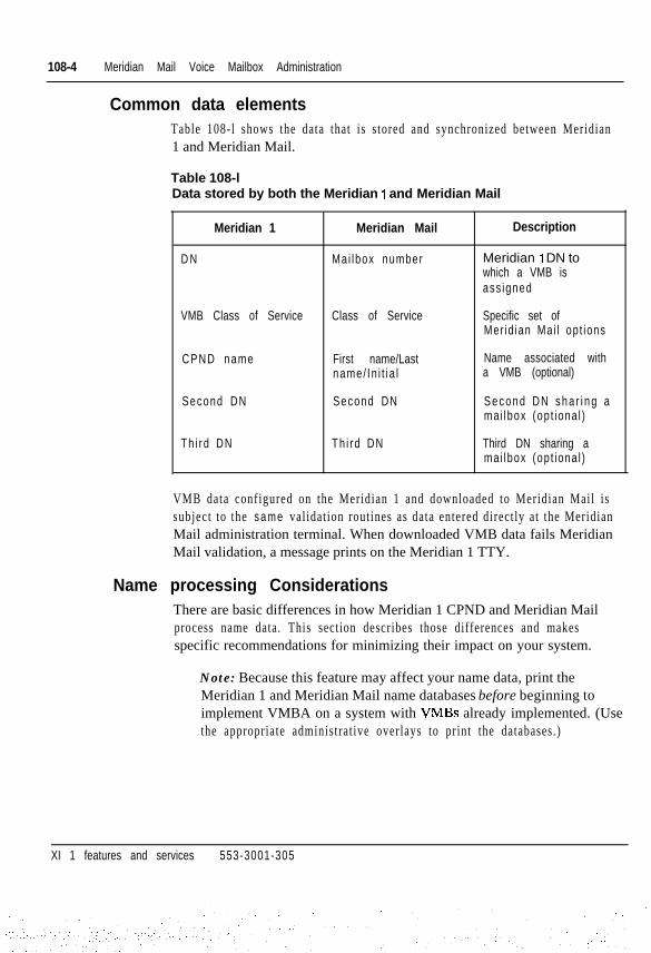
Common data elementsTable 108-l shows the data that is stored and synchronized between Meridian1 and Meridian Mail.
Table 108-lData stored by both the Meridian 1 and Meridian Mail
Meridian 1 Meridian Mail Description
D N Mai lbox number Meridian 1 DN towhich a VMB isass igned
VMB Class of Service Class of Service Specific set ofMer id ian Mai l opt ions
CPND name
Second DN
First name/Lastname/ In i t i a l
Second DN
Name associated witha VMB (optional)
S e c o n d D N s h a r i n g amai lbox (opt iona l )
Th i rd DN Th i rd DN Third DN sharing amai lbox (opt iona l )
VMB data configured on the Meridian 1 and downloaded to Meridian Mail issubject to the same validation routines as data entered directly at the MeridianMail administration terminal. When downloaded VMB data fails MeridianMail validation, a message prints on the Meridian 1 TTY.
Name processing ConsiderationsThere are basic differences in how Meridian 1 CPND and Meridian Mailprocess name data. This section describes those differences and makesspecific recommendations for minimizing their impact on your system.
Note: Because this feature may affect your name data, print theMeridian 1 and Meridian Mail name databases before beginning toimplement VMBA on a system with VMBs already implemented. (Usethe appropriate administrat ive overlays to print the databases.)
XI 1 features and services 553-3001-305

Meridian Mail Voice Mailbox Administration 108-5
Name lengthsXI 1 release 18 versus Xl 1 release 19In X11 release 18 and earlier, CPND stores names on the Meridian 1 in asingle 27-character field. In X11 release 19 and later, CPND stores names intwo fields (first name and last name) with a combined length of up to 27characters. A conversion from X11 release 18 to X11 release 19 includes thefollowing name processing:
- The entire contents of the X11 release 18 CPND name field is placed inthe X11 release 19 first name field.
- The contents of the X11 release 19 last name field is set to blanks.
Although this processing preserves exist ing name data, no automated way isprovided for separating name data into first and last name. Therefore, aftercomplet ing the conversion, you may want to consider using the uploadfunction of VMBA. This function replaces Meridian 1 CPND name data withMeridian Mail name data, which is separated into first and last name.
Meridian 1 versus Meridian MailBecause the allowable name lengths differ between Meridian Mail andMeridian 1, i t is recommended that you use the most restr ict ive case for namelengths on both sys tems.
Meridian Mail accepts the following name lengths:
- Up to 21 characters for first name
- Up to 40 characters for last name
- Up to 61 characters for combined first and last names
In X11 release 19, Meridian 1 CPND accepts the following name lengths:
- Up to 27 characters for first name
- Up to 27 characters for last name
- Up to 27 characters for combined first and last names
Xl 1 features and services 553-3001-305
I

108-6 Meridian Mail Voice Mailbox Administration
When the VMBA applicat ion is instal led, the recommended name lengths onboth Meridian 1 and Meridian Mail are as follows:
- Up to 21 characters for first name. Meridian Mail truncates a Meridian 1first name that is longer than 21 characters.
- Up to 27 characters for combined first and last names. If names onMeridian Mail exceed a combined length of 27 characters, they aretruncated on the Meridian 1 during an upload.
- Up to 27 characters for last name. Last names are truncated to 27characters when uploaded.
Name handling during an uploadIf the CPND package is equipped and CPND is configured for the customer,the fol lowing name processing occurs during an upload:
1 If a name already exists on the Meridian 1, it is replaced with theuploaded name using the expected length (XPLN) and display formatsconfigured for that name.
2 If a name does not exist on the Meridian 1, the uploaded name is addedusing the default length (DFLN) specified for the customer and thedefault display format of FIRST,LAST.
3 If the names received from Meridian Mail are longer than the expectedor default length, the f i rs t name is t runcated unti l both names f i t into theconfigured length. If necessary, the last name is also truncated.
For example, if Meridian Mail sends the name JACK FROST and XPLN is8, the name is truncated to JA FROST. If XPLN is 4, the name is truncated toFROS.
A subsequent audit with DATA-CORRECT set to ON causes the name onMeridian Mail to be updated with the Meridian 1 name (either JA FROST orFROS).
Xl 1 features and services 553-3001-305
. ...:

Meridian Mail Voice Mailbox Administration 108-7
Character setsMeridian Mail supports a subset of the characters that Meridian 1 supports .When Meridian Mail encounters a name from the Meridian 1 that containscharacters outside its supported character set, i t rejects the name. Therefore,i t is recommended that you use the most restr ict ive character set .
The character sets supported by the Meridian 1 and Meridian Mail are asfollows:
- Meridian 1: ASCII H.20 through H.7E, excluding asterisk (*) andexclamation point (!)
- Meridian Mail: ASCII H.20 through H.7E excluding the plus sign (+),underscore 0, and question mark (?)
Therefore, on a system with VMBs, the Meridian 1 user should avoid usingthe asterisk (*), exclamation point (!), plus sign (+), underscore (J, andquestion mark (?) in CPND names.
Xi 1 features and services 553-3001-305

108-8 Meridian Mail Voice Mailbox Administration
Database synchronization considerationsAs you configure and implement VMBA, keep the following points in mind.
- Meridian 1 and Meridian Mail each has its own name database.Therefore, to ensure synchronization, enter and change nameinformation from the Meridian 1 VMBA facilities ensure thatcorresponding changes are made to the Meridian Mail database.However, remember that changes made directly to the Meridian Mail arenot made to the Meridian 1 database.
- The VMBA Audit facility not only detects VMB database mismatches.With Data Correction enabled, the Audit facility invokes processing tomake the Meridian Mail VMB database match the Meridian 1 VMBdatabase. See Table 108-2.
Table 108-2Effect of running Audit with Data Correction enabled
Status of VMB
Meridian 1 Meridian Mail
VMB not con f igured VMB not con f igured
VMB not con f igured VMB conf igured
VMB conf igured VMB not con f igured
VMB conf igured VMB conf igured;da tabase matchesMeridian 1
Effect on VMB databases
Meridian 1 Meridian Mail
No change No change
No change No change
No change VMB added
No change No change
VMB conf igured VMB configured;database does notmatch Meridian 1
No change VMB da tabasechanged to ma tchMer id ian 1 da tabase
Xl 1 features and services 553-3001-305

Meridian Mail Voice Mailbox Administration 108-9
- The VMBA Upload facility forces the Meridian 1 VMB database tomatch the Meridian Mail VMB database. In the case where VMB is notconfigured on Meridian Mail , an upload wil l delete the Meridian 1 VMBdatabase. See Table 108-2.
Table 108-3Effect of running Upload
Status of VMB
Meridian 1 Meridian Mail
VMB not con f igured VMB not con f igured
VMB not con f igured VMB conf igured
VMB conf igured VMB not con f igured
VMB conf igured VMB configured;database matchesMer id ian 1
Effect on VMB databases
Meridian 1 Meridian Mail
No change No change
VMB added No change
VMB de le ted No change
No change No change
VMB conf igured VMB configured;database does notmatch Meridian 1
VMB da tabasechanged to matchMer id ian Mai lda tabase
No change
Feature packagingMeridian Mail Voice Mailbox Administration (VMBA) is available aspackage 246. It requires X11 release 19 on the Meridian 1, and Meridian MailM M 9 .
Although not required, Calling Party Name Display (CPND), package 95, forthe Meridian 1 is recommended. Certain Meridian Mail features, such asname dialing, require that CPND be equipped.
Alarm Filtering, package 243, is recommended because of the additionalinformation that appears in the formatted output .
Xl 1 features and services 553-3001-305
108-10 Meridian Mail Voice Mailbox Administration
Feature implementationBe sure to print the name databases for both the Meridian 1 and MeridianMail before beginning to implement the VMBA application.
Implementing VMBA requires that it be installed and equipped on theMeridian 1. (In addition, Meridian Mail must be MM9 or later.) This sectionincludes instruct ions for three implementat ion scenarios:
1 A site with no preconfigured database on either the Meridian 1 orMeridian Mail.
2 A site with a preconfigured database on the Meridian 1 but not onMeridian Mail.
3 A site with VMBs configured on Meridian Mail, but not on theMeridian 1.
Xl 1 features and services 553-3001-305

Meridian Mail Voice Mailbox Administration 108-l 1
Site with no preconfigured database
1 If necessary, configure and enable the AML link to Meridian Mail. Forassistance, refer to the Meridian Link descr ipt ion (553-3201-110).
2 Configure the VMBA application in LD17 on the VAS link associatedwith Meridian Mail. Set the DATA-CORRECT and AUTO-AUDIToptions to ON to simplify database maintenance and ensure datain tegr i ty .
Table 108-4LD17-Configuring the VMBA application
Prompt Response
R E Q N E W
TYPE CFN, VAS
VAS N E W , C H G
Description
Configuration Data Block 1
Add or change a value addedserver link
VSID
AML
APPL
o-1 5
o-1 5
NEW VMBA
VAS ident i f ie r
Application Module Link identifier
Conf igure the VMBA app l ica t ionassociated with a VSID
C U S T o-99
DATA-CORRECT ON
Customer number
Enab le au tomat i c da tabasecorrection during audit; theMeridian Mail database isupdated to match the Meridian 1database.
AUTO-AUDIT O N Enab le au tomat i c da tabaseaudit; the Meridian Mail databaseis audited every 5 days as part ofdaily routines.
If the AML link is active, the VMBA application is automaticallyenabled after it is configured in LD17. If the AML link is not active, theVMBA application is placed in the LINKOOS (link out of service)s ta tus .
Xl 1 features and services 553-3001-305

108-12 Meridian Mail Voice Mailbox Administration
3 Configure the VMB classes of service on Meridian Mail. Transactionerrors occur if a class of service specified on the Meridian 1 has not beenconfigured on Meridian Mail.
4 Use LDs 10 and 11 to administer VMBs on the Meridian 1. The databasechanges are automatically downloaded to Meridian Mail if both theAML and the VMBA application are enabled. If either is disabled, theVMBs that are added or changed are left in the UPDATE PENDINGstate. They are downloaded when both the AML link and application areenabled. See Tables 108-5 and 108-6.
Table 108-5LDlO-Add aVMB on a 500/2500 telephone
Prompt
REQ
TYPE
T N
CUST
D N
-MARP
-CPND
VMB-
Response Description
N E W , C H G
500,250O DN related data
l s c u Termina l number
o-99 Cus tomer number
xxxx Di rec to ry number
YES Mul t ip le Appearance Red i rec t ion Pr ime
N E W , C H G Gateway to change Calling Party NameDisplay data
N E W , C H G Gateway to change VMB dataassociated with the above DN
VMB-COS O - 1 2 7- VMB Class of Service; must already bedefined on Meridian Mail to avoidt ransac t ion e r ro rs
- S E C O N D - D N xxx...x Second DN sharing this VMBTo delete a DN, enter X <cr>
THIRD-DN xxx...x- Third DN sharing this VMBTo delete a DN, enter X <cr>
- KEEP-MSGS YES, (NO) For a new VMB only, indicates whethermessages and current password onMeridian Mail should be preserved if aVMB with the same DN already exists
Xl 1 features and services 553-3001-305

Meridian Mail Voice Mailbox Administration 108-13
Table 108-6LDl l-Add a VMB on a digital telephone
Prompt Response
R E Q N E W
TYPE a a a a
T N l s c u
C U S T o-99
KEY xx yyy zzzz
Description
Telephone type
Termina l Number
Cus tomer Number
Telephone function keyass ignmen ts
-MARP YES Mul t ip le Appearance Red i rec t ionPr ime
-CPND N E W , C H G Gateway to Calling Party NameDisplay data
VMB- N E W , C H G Gateway to change VMB dataassociated with the above DN
-SECOND-DN xxx...x Second DN sharing this VMBTo delete a DN, enter X <cr>
THIRD-DN- xxx...x Second DN sharing this VMBTo delete a DN, enter X <cr>
-KEEP-MSGS YES, (NO) For a new VMB only, indicateswhether messages and cur ren tpassword on Meridian Mailshould be preserved if a VMBwith the same DN already exists
Xi 1 features and services 553-3001-305
. - - .

108-14 Meridian Mail Voice Mailbox Administration
Site with a preconfigured Meridian 1 databaseTypically, this scenario involves a new Meridian 1 instal lat ion. The databaseis created on the Meridian 1 and subsequently downloaded when the AMLlink and Meridian Mail are operational.
Configuring the database
1 Configure the VMBA application in LD17 on the VAS associated withMeridian Mail. See Table 108-4 page 108-11. Set theDATA-CORRECT and AUTO-AUDIT options to OFF until theinstallation is complete.
The AML link does not have to be configured at this point because thereis no actual hardware to enable.
2 Configure the telephones and associated VMBs. The VMBs will be leftin UPDATE PENDING state. See Tables 108-5 and 108-6.
Installing the database at the customer site
Ensure that the Meridian Mail database is configured with the VMBclasses of service that were used when configuring the Meridian 1database. Do not proceed wi th Step 2 unt i l th is s tep is completed.
If necessary, configure and enable the AML link to Meridian Mail. Forassistance, refer to the Meridian Link description (553-3201-110).
Unless the VMBA application is in a manually disabled state, it will beautomatically enabled. If it is manually disabled, use LD48 to enable it.See “Enabling the VMBA application” on page 108-17.
When the VMBA application is enabled, the system will begindownloading the preconfigured database to Meridian Mail . Use the PRTVMB option in LD20 to monitor the progress of the download.
After the download is complete, check the Meridian 1 TTY for errors andmake corrections manually.
Xl 1 features and services 553-3001-305
.:: -. :.

Meridian Mail Voice Mailbox Administration 108-15
6 Use LD48 to initiate a manual audit of the entire database. This is toverify that the VMB and CPND data on the Meridian 1 matches thedownloaded data on Meridian Mail. See “Starting a manual audit” onpage 108-26.
To determine the status of the audit , use the STATVMBA cvsid> AUDTcommand in LD48. When the audit is complete, check the audit reportfor errors; make corrections manually.
7 Configure the DATA-CORRECT and AUTO-AUDIT options asdesired. I t is recommended you set them to ON to help ensure databasein tegr i ty .
Installation is now complete. Use the Meridian 1 to perform ongoingadministration of VMBs.
Site with a preconfigured Meridian Mail databaseExisting sites installing the VMBA application may have VMBs alreadyconfigured on Meridian Mail . LD48 includes an upload option that s implif iesVMB data configuration on the Meridian 1.
CAUTIONThe upload option also causes name data configured on Meridian Mailto be uploaded to the Meridian 1. Any exist ing names on the Meridian1 are replaced with names currently configured on Meridian Mail. See“Name processing considerations” on page 108-4 for an explanationof the changes that may result .
1 If necessary, configure and enable the AML link to Meridian Mail. Forassistance, refer to the (553-3201-110).
2 Configure the VMBA application in LD17 on the VAS associated withMeridian Mail. See Table 108-4, on page 11. Set the DATA-CORRECTand AUTO-AUDIT options to OFF until the installation is complete.
If the AML link is active, the VMBA application is automaticallyenabled after it is configured in LD17. If the AML link is not active, theVMBA application is placed in the LINKOOS (link out of service) state.
Xl 1 features and services 553-3001-305

108-16 Meridian Mail Voice Mailbox Administration
3 Initiate the database upload by entering the following command inLD48:
ENL VMBA <vsid> UPLD ALL
To check the s t a t u s of the upload, enter the fol lowing command in LD48:
STAT VMBA <vsid> UPLD
4 When the VMB UPLOAD COMPLETE message appears, investigateand resolve any errors that occurred during the upload.
5 Initiate a manual database audit using the following command in LD48:
ENL VMBA <vsid> AUDT ALL
This wil l verify that the VMB and CPND data on the Meridian 1 matchesthe data on Meridian Mail.
6 Manually resolve any errors detected by the audit . Perform any necessaryname cleanup.
7 Configure the DATA-CORRECT and AUTO-AUDIT options asdesired. It is recommended you set them to ON to help ensure databaseintegr i ty .
Installation is now complete. Use the Meridian 1 to perform ongoingadministration of VMBs.
Xi 1 features and services 553-3001-305
__- :_ :
Meridian Mail Voice Mailbox Administration 108-17
Feature operationEnabling the VMBA application
Use the VAS gateway in LD17 to configure the VMBA application. SeeTable 108-4, on page 11. After configuring the VMBA application, theMeridian 1 sets the VMBA application state to INACTIVE and immediatelyattempts to establ ish a VMBA session with Meridian Mail . I f successful , theMeridian 1 changes the VMBA application state to ACTIVE and prints anAPPLICATION ENABLED message on the TTY. If unsuccessful, thefollowing actions occur:
- If the AML link is down:
. The system issues a FAILED TO ENABLE APPLICATIONmessage to the TTY.
. The application’s state is changed to LINKOOS (link out ofservice).
l The application is automatically enabled when the link becomesavailable.
- If the AML link is up but the application is not responding on MeridianMail:
. The system at tempts to es tabl ish a session every two minutes unt i lsuccessful or unt i l the user disables the applicat ion using LD48.
- If the AML link is up but the application is not equipped on MeridianMail:
. For MM8 and earlier releases, the system attempts to establish asession as described above. Such at tempts obviously fai l . DisableVMBA until the upgrade to MM9 occurs.
. For MM9 and later releases, Meridian Mail indicates to theMeridian 1 that the feature is not configured. The message FAILEDTO ENABLE APPLICATION appears on the TTY, indicating thatthe request is rejected. The application remains in INACTIVEstatus. Retr ies continue unt i l the user disables the applicat ion inLD48 or until the application is equipped on MM9.
Xi 1 features and services 553-3001-305

108-18 Meridian Mail Voice Mailbox Administration
If the VMBA application is not automatically enabled, use the followingcommand in LD48 to enable it:
ENL VMBA cvsid>
where cvsid> is the VAS identifier, in the range of O-15.
Disabling the VMBA applicationLD48 accepts the following command to disable the VMBA application:
DIS VMBA <vsid>
where <vsid> is the VAS identifier, in the range of O-15.
The following actions occur when the application is disabled:
1 The VMBA application state is changed from ACTIVE to MANDIS.
2 All VMB transactions in progress with Meridian Mail are aborted.VMBs defined on the Meridian 1 but not successfully updated onMeridian Mail remain in the UPDATE PENDING state. They will beprocessed when the application is reenabled.
3 Database audit or upload activit ies are aborted.
4 The VMBA session established with Meridian Mail is released.
Xi 1 features and services 553-3001-305

Meridian Mail Voice Mailbox Administration 108-19
Determining the status of the VMBA applicationLD48 accepts the following command to print the status of the VMBAapplicat ion:
STAT VMBA <vsid>
where <vsid> is the VAS identifier, in the range of O-15.
Output from this command, shown in the following example, indicates thestatus of the applicat ion, the audit function, and the upload function:
VMBA ACTIVEAUDIT INACTIVEUPLOAD INACTIVE
Valid application states for VMBA appear in Table 108-7.
Table 108-7VMBA Application States
State
INACTIVE
Explanation
The application has been configured in LD17 but isinactive for one of the following reasons:
- An application session request was sent toMeridian Mail but confirmation has not yet beenrece ived.
- Meridian Mail is not configured to support theVMBA application (it does not have theapplication equipped, or it is running on MM8 orear l ie r ) .
- A FAILED TO ENABLE APPLICATION messageon the TTY indicates a reason why theapplication is inactive.
MANDIS
LINKOOS
The application was manually disabled using LD48.
The application is inactive because the link toMeridian Mail is out of service.
ACTIVE The application is enabled and operational.
Xi 1 features and services 553-3001-305

108-20 Meridian Mail Voice Mailbox Administration
Managing voice mailbox dataAdding or changing a VMBUse LDs 10 and 11 to add or change a VMB. See Tables 108-5 onpage 108-12 and Table 108-6 on page 108-13. Use LDs 10, 11, or 95 to addor change a name.
When a VMB is added or changed, the system places the VMB in theUPDPEND (update pending) state and informs a background process that anupdate is pending. The background process init iates an update transactionwith Meridian Mail, with one of these outcomes:
- The operation is successful; the VMB state becomes CONFIGURED.
- The operation fails (perhaps because of bad data); the VMB statebecomes UPDFAIL (update failed) and a craftsperson must manuallyintervene to correct the error condition.
- If the VMB already exists on Meridian Mail when the Meridian 1requests a VMB add, one of the following outcomes results.
. If the response to the KEEP-MSGS prompt in LDs 10 and 11 wasNO, Meridian Mail deletes the existing VMB and creates a new oneusing the configurat ion information specif ied by the Meridian 1. Allexist ing messages and passwords are deleted.
. If the response to the KEEP-MSGS prompt in LDs 10 and 11 wasYES, Meridian Mail keeps all existing messages and passwordsassociated with the VMB, but replaces the existing configurationinformation with the new configurat ion specif ied by the Meridian 1.This information includes user name, class of service, and so forth.Meridian Mail automatically enables newly created VMBs.
Deleting a VMBThere are three ways to delete a VMB:
- When using LDs 10 and 11, enter OUT at the VMB prompt.
When doing a normal CHG or ECHG on a telephone in LDs 10 and 11,enter OUT at the VMB prompt to delete the telephone’s VMB.
- When using LDs 10 and 11 to delete a telephone, enter OUT at the REQprompt .
Xl 1 features and services 553-3001-305

Meridian Mail Voice Mailbox Administration 108-21
If a telephone is configured with a single appearance DN, theDELETE-VMB prompt appears as a prompt after the craftsperson entersOUT at the REQ prompt. A YES response causes the VMB to be deletedon both the Meridian 1 and Meridian Mail . A NO response causes theVMB to be deleted on Meridian 1 but not on Meridian Mail.
The DELETE-VMB and the KEEP-MSGS prompts allow acraftsperson to move a user from one telephone type to another withouthaving to delete and recreate the VMB.
. DELETE-VMB = NO when deleting a DN keeps the old mailbox.KEEP-MSGS = YES when adding a new telephone (with the old,previously deleted DN) keeps VMB messages and password fromthe old DN intact.
. DELETE-VMB = NO when deleting a DN keeps the old mailbox.KEEP-MSGS = NO when adding a new telephone (with the old,previously deleted DN) deletes the VMB messages and passwordassociated with the mailbox.
When changing a single appearance DN on a telephone, the systemautomatically deletes the old DN and associated VMB.
When the changed DN is entered, if i t is currently assigned to anothertelephone that has a VMB associated with i t , the telephone with thechanged DN becomes a user of that VMB. If the changed DN does notcurrently have a VMB, one can be added.
Note: When changing the DN for a member of a multi-appearance DNgroup, the VMB for the Multi-Appearance DN is unaffected.
Xl 1 features and services 553-3001-305

108-22 Meridian Mail Voice Mailbox Administration
Printing VMB data
LDs 20 and 83 support print ing VMB data associated with a telephone. WithX11 release 19 and later, LDs 10 and 11 can access LD20 to faci l i ta te pr int ingVMB data after it is entered.
LD20 provides three ways to print VMB data:
- Use the PRT DNB command to print the DN block. See Table 108-8.
Table 108-8LD20 - Print the DN block
Prompt Response
R E Q P R T
TYPE D N B
CUST 0-9s
D N xxxx
Description
DN related information
Cus tomer Number
D i rec to ry Number
- Use the PRT TNB command to print the TN block. See Table 108-9.
Table 108-SLD20 - Print theTN block
Prompt
R E Q
TYPE
T N
Response
P R T
TNB, aaaa
l s c u
Description
TN block, or any telephoneconfigured in LDl 1
Termina l Number
Xi 1 features and services 553-3001-305

Meridian Mail Voice Mailbox Administration 108-23
- Use the PRT VMB command to print the VMB DN and VMB state. SeeTable 108-10. For a definition of each state, see TablelOS-11 .
Table 108-l 0LD20 - Print VMB data
Prompt
REQ
TYPE
C U S T
D N
Response
P R T
VMB
o-99
xxxxXxXx-YYYY(ALL)
Description
VMB re la ted in fo rmat ion
Cus tomer Number
Print data for a single DNPrint data for a range of DNsPrint data for all DNs with VMBs
VMB-STATE ( A L L ) Print all VMBs regardless of stateUPDPEND Print VMBs in update pending stateCONFIGURED Print configured VMBsUPDFAIL Print VMBs whose updates failedM I S M A T C H Print VMBs with database mismatchesUPDINPROG Print VMBs with updates in progressINVAL ID Print VMBs in an invalid state
Xl 1 features and services 553-3001-305
..:

108-24 Meridian Mail Voice Mailbox Administration
Table 108-I 1VMB States
State
CONFIGURED
UPDPEidD
UPDINPROG
UPDFAIL
M I S M A T C H
INVAL ID
Explanation
The VMB is configured on the Meridian 1 and Meridian Mail.
A VMB update is pending. The VMB has been added or changed on theMeridian 1 but Meridian Mail has not yet been updated. When the AML linkcomes up (if it is down), or when the backlog of updates (if any) isprocessed, the VMB will be updated automatically.
A VMB update is in progress. The request was sent to Meridian Mail but aconfirmation has not yet been received by the Meridian 1.
A transaction with Meridian Mail failed. AVMB UPDATE FAIL error messageappears on the Meridian 1 TTY indicating the cause of the failure. Acraftsperson must intervene to correct the problem.
There is a database mismatch between the Meridian 1 and Meridian Mail.The mismatch was detected by VMBA Audit but not corrected (becausedatabase correction is not enabled in LDI 7). A VMB MISMATCH FOUNDerror appears on the Meridian 1 TTY indicating the mismatch. Acraftsperson must intervene to correct the problem.
The VMB is in an invalid state. Verity that the VMB data for the DN is correcton the Meridian 1. Then use LD48 to run VMB Audit on the DN.
- To print VMB data in LD83, respond with TNB at the REQ prompt. Thisresponse causes the TN block to print, including VMB data. SeeTable 108-12.
Table 108-12LD83 - Print ODAS data
Prompt Response Description
REQ TN6 Print TN data
CUST o-99 Cus tomer Number
Determining VMB stateReview the printed VMB data to determine the status of a particular VMB.Valid VMB states appear in Table 108-11.
Xl 1 features and services 553-3001-305
:’ -.-

Meridian Mail Voice Mailbox Administration 108-25
Auditing the VMB databaseThe VMBA applicat ion provides both automatic and manual synchronizat ionprocedures to help ensure the consistency of the Meridian 1 and MeridianMail databases. The databases may lose synchronization during one of thefol lowing events :
- A craftsperson changes VMBs directly on Meridian Mail rather thanthrough the Meridian 1.
- A transact ion error occurs during transmission between the Meridian 1and Meridian Mail.
CAUTIONLD17 includes a data correction setting (DATA-CORRECT = ON).With this option act ivated when an audit is run, the system resolvesany discrepancy by changing the Meridian Mail database to match theMeridian 1 database. If the databases are out of synchronizationbecause VMB data was changed directly on Meridian Mail, the auditreplaces the changed Meridian Mail data with the original Meridian 1data. Therefore, it is advisable to run an audit initially withDATA-CORRECT = OFF to determine what discrepancies (if any)exist.
Using automatic auditResponding with ON to the AUTO-AUDIT prompt in LD17 causes adetailed database consistency check to run every five days. During this audit ,Meridian Mail compares its VMB data with each Meridian 1 DN’s data.There are three possible results:
- The data for that DN matches.
Meridian Mail indicates a match to the Meridian 1.
- The data for that DN does not match, and DATA-CORRECT = ON.
Meridian Mail changes its data to match the data on the Meridian 1. Amessage appears on the Meridian 1 TTY indicating that a discrepancywas detected and corrected.
- The data for that DN does not match, and DATA-CORRECT = OFF.
Xi 1 features and services 553-3001-305
: ,

108-26 Meridian Mail Voice Mailbox Administration
A message appears on the Meridian 17TY indicating that a discrepancywas detected. Manual intervention is required to correct the discrepancy.
Starting a manual auditTo start the audit function manually, use the ENL VMBA command with theAUDT option in LD48. The format of the command is as follows:
ENL VMBA cvsid> AUDT <ALL, xxxx>
where:
cvsid> is the VAS ID on which the application is configuredALL specifies that all configured VMBs be auditedxxxx specifies the DN whose VMB is to be audited
Disabling auditUse the DIS VMBA with the AUDT option to disable the audit funct ion. Theformat of the command is as follows:
DIS VMBA <vsid> AUDT
where <vsid> is the VAS ID.
This command disables both automatic and manual audits.
Determining audit statusUse the STAT VMBA with the AUDT option to determine the status of anaudit. The format of the command is as follows:
STAT VMBA cvsid> AUDT
where cvsicb is the VAS ID.
Output from this command takes the following format:
AUDIT ACTIVEx AUDITEDy MISMATCHES FOUND/CORRECTEDz ERRORS
where:
x is the number of VMBs auditedy is the number of mismatches found (and corrected, ifDATA-CORRECT = ONz is the number of failed audit operations
Xi 1 features and services 553-3001-305
. . :
I

Meridian Mail Voice Mailbox Administration 108-27
Uploading the Meridian Mail VMB databaseExisting sites installing the VMBA application may already have VMBsconfigured on Meridian Mail . To eliminate the need for a craftsperson to addeach VMB manually on the Meridian 1, the VMBA application includes theability to upload the Meridian Mail VMB database to the Meridian 1.
The VMB upload command in LD48 causes the following processing, if theALL option is specified. The processing is applied to all SCR, SCN, MCR,and MCN DNs configured on the Meridian 1.
1 For each DN on the Meridian 3, Meridian Mail checks to see if a VMBis currently defined.
2 If a Meridian Mail VMB exists for the DN, the VMB data associated withthe DN, including the VMB name, is uploaded to the Meridian 1. TheMeridian 1 uses the uploaded data to create VMB data and name (or toreplace existing VMB data and name) for that DN.
CAUTIONIf the second or third DNs received from Meridian Mail are greaterthan four digits (or seven digits, if the DN expansion feature isequipped), they are discarded. A subsequent audit with data correctionenabled deletes them from Meridian Mail.
, I
3 If a Meridian Mail VMB does not exist for the DN, and if a VMB iscurrently configured for the DN on the Meridian 1, the VMB is deleted.
Note: A name currently configured for the DN on the Meridian 1 is notdeleted.
Starting a database uploadTo start a database upload, use the ENL VMBA command with the UPLDoption in LD48. The format of the command is as follows:
ENL VMBA <vsid> UPLD -zALL,xxxx>
where:
cvsidz is the VAS ID on which the application is configuredALL specifies that data for all configured VMBs is to be uploadedxxxx specifies the DN whose VMB data is to be uploaded
Xl 1 features and services 553-3001-305

108-28 Meridian Mail Voice Mailbox Administration
Disabling a database uploadUse the DIS VMBA with the UPLD option to disable the upload. The formatof the command is as follows:
DIS VMBA cvsid> UPLD
where <vsid> is the VAS ID.
Determining upload statusUse the STAT VMBA with the UPLD option to determine the status of anupload. The format of the command is as follows:
STAT VMBA <vsid> UPLD
where cvsidr is the VAS ID.
Output from this command takes the following format:
UPLOAD ACTIVEx UPLOADEDy DELETEDz E R R O R S
where:
x is the number of VMBs uploadedy is the number of VMBs deletedz is the number of failed upload operations
Xl 1 features and services 553-3001-305
Issued: 9 2 1 2 3 1Status: Standard
Xl 1 Release: 9 1Meridian Manager
109-l
Note: Meridian Manager is supported with Xl 1 release 17 and earlieron ly .
Meridian Manager consists of the following three personal computer-basedappl icat ions:
- Station Administration This user-friendly interface to the SL-1 allowsaddit ions, moves, and changes within SL- 1 Telephone Data Blocks(LDlO and LDI 1).
- Work Order System This application provides administrationdatabases for the handling of inventories, configurations, work ordersand cabling records.
- Traffic Reporting This application collects, processes, and analyzestraffic data taken from the SL-1 system. The performance of the SL- 1 isoptimized by providing clear, easy to understand graphs and reports ontrunks, attendants, at tendant queues, network loops, and processor use.
The three Meridian Manager applications run under MS-DOS. MeridianManager software is supported on the IBM PC AT and PS/2, CompaqDeskPro and Hewlett-Packard Vectra personal computer families. Theapplications are available individually or together in one package.
Complete instructions for installing and operating Meridian Managersoftware packages can be found in the following Northern Telecomdocuments:
- Feature Description (PO707599)- StationAdministration (PO707698)- Work Order System (PO707699)- TraJfic Reporting (PO707700)
Xi 1 features and services 553-3001-305

109-2 Mer id ian Manager
Operating parametersRefer to the documents l is ted.
Feature interactionsRefer to the documents l is ted.
Feature packagingNot applicable.
Feature implementationNot applicable.
Feature operationNot applicable.
Xl 1 features and services 553-3001-305

Meridian MAX/ACD-MAXMeridian MAX and ACD-MAX are management tools that supplement theAutomatic Call Distribution (ACD) feature on the Meridian USL- 1. MeridianMAX and ACD-MAX compile and display ACD operat ions information andgenerate management reports. Meridian MAX and ACD-MAX are connectedto the Meridian I/SL-1 through one or two Serial Data Interface (SDI) ports.
The specific functions Meridian MAX and ACD-MAX perform include thefollowing: I- receive agent, queue, and trunk status data from the Meridian USL-1
- calculate the necessary statistics
- display data for current performance and store data for past-performancereports
- generate and print al l performance reports based on historical data
- offer configuration control
- schedule and create report definit ions
- manage current-performance display screens
- provide a menu-driven interface for supervisors
- manage the various parameters set by the system administrator I
The following platforms exist. Meridian MAX 4.0 is an AM-base productdesigned for an Option 21-81. A single-module system supports up to 150ACD posi t ions and 3000 cal ls per hour. The dual-module system supports upto 500 ACD positions (which can be increased to 1000 via a purchasableoption) and handles 10,000 calls per hour.
Xl 1 features and services 553-3001-305
. . . . ...:. ..:

110-2 Meridian MAX/ACD-MAX
The Meridian MAX-IPE 4.6 is an Intelligent Peripheral Equipment modulethat fits into the Option 11 or the Option 21-81. It is designed to meet theneeds of smaller customers. Meridian MAX-IPE 4.6 provides the samefunctionality as the single-module Meridian MAX 4.0 except that it hasflexible ACD position sizing up to 8d positions.
ACD-MAX is an HP-base product designed for the Option 21-81. Asingle-tower system supports up to 150 ACD positions and 3000 calls perhour. The dual-tower system supports up to 500 ACD positions (which canbe increased to 1000 via a purchasable option) and handles 10,000 calls perhour.
Related documentsFor complete information regarding ACD-MAX and Meridian MAX, see thefollowing documents.
ACD-MAX
- Master Index (553-4001-003)
- ACD-MAX Znstallation (553-4001-110)
- ACD-MAX Operations (553-4401-510)
- ACD-MAX System Messages (553-4001-810)
- ACD-MAX Overview (553-4001-910)
- ACD-MAX 3.0 Supervisor’s User Guide (PO706646)
Meridian MAX 4.0
- Applicat ion Equipment Module ins tal lat ion guide (553-3201-200)
- Master Index (553-4001-002)
- Meridian MAX 3.3-AM Znstallation (553-4001-101)
- Meridian MAX 3.3-AM System Messages (553-4001-801)
- Meridian MAX 3.3-AM Overview (553-4001-901)
- Meridian MAX 3.3 Supervisor‘s User Guide (PO734369)
Xl 1 features and services 553-3001-305
.._.

Meridian MAXIACD-MAX 110-3
Meridian MAX-IPE 4.6
Master Index (553-4001-024)
- Meridian MAX-IPE 4.6 Installation (553-4001-121)- Meridian MAX-IPE 4.6 Maintenance and Diagnostics (553-4001-821)
- Meridian MAX-IPE 4.6 Overview (553-4001-921)
- Meridian MAX-IPE 4.6 Supervisor’s Guide (P0741145)
Xl 1 features and services 553-3001-305

110-4 Meridian MAX/ACD-MAX
Xl 1 features and services 553-3001-305
: - . ‘. .-: .,I... :.

Message CenterMessage Center al lows an incoming trunk or internal cal l to be automatical lyrouted to a Message Center i f i t is not answered at the original dest inat ion.The main functions of the Message Center are to
- receive and take messages for calls forwarded to the Message Center
- convey messages to called telephones or consoles on request
- activate and deactivate Message Waiting indication at users’ telephones
Automatic and manual diagnostics are provided to clear al l active MessageWaiting indications when required. Three types of Message Centeroperations are offered:
- SL- 1 and Meridian digi tal telephone
- attendant console
- Automatic Call Distribution (ACD)
Depending on the packages equipped, you can have any Message Centeropt ion or combinat ion of Message Center opt ions.
For complete information, see Message Center descr ip t ion and operat ion(553-2691-100).
Network Message Services-Message Center (NM&MC) X11 release 15introduces Network Message Center. For a complete discussion, see thefeature module on Network Message Services.
Xl 1 features and services 553-3001-305
_: :

111-2 Message Cen te r
Xi 1 features and services 553-3001-305
,:. .‘...
.. ,

112-1
Message RegistrationMessage Registration (MR) allows customers to meter local calls so thatHospital i ty administrat ion can read, change, and reset message units storedon the meters .
Software meters accumulate call charges for room phones, administrationphones, customer phones, at tendant consoles, incoming t ie trunks, andCentral Office (CO) trunks.
Operating parametersMeters are incremented when Reverse Battery (RVB) signals are receivedfrom loop start or ground start Central Office (CO) trunks. The meter isincremented once for each completed local call, regardless of duration,against the originating Directory Number (DN). No charge is made to anymeter if a call over a metered route is not established.
Metering is applied on a route basis . When provisioning a customer for theMR feature, calls that are to be metered can have access only to routes thatare metered. Metered calls cannot be overflowed to a nonmetered route.
One software meter is assigned to every telephone Directory Number (DN),attendant DN, and Trunk Access Code (TRC) that requires metering. Eachsoftware meter can count up to 32,766 calls before being automatically resetto zero. Prior to reset , the meter contents are displayed on the systembackground terminal.
Xl 1 features and services 553-3001-305

112-2 Message Reg is t ra t ion
The ATTN meter accumulates charges for all metered calls made byattendant consoles within a customer group. The TRK meter is provided foreach incoming tie trunk route and Central Office (CO) route. Charges areregistered for tandem call connections made by incoming tie trunks over ameter-assigned route. One ovefflow meter, the CUST meter, allows eachcustomer to accumulate any charges that cannot be registered to anothermeter.
With call modification, the party originating the metered call has its metercharged. Once the meter is charged, the charge cannot be transferred toanother party’s meter through Call Modification.
Attendant-originated calls to metered routes are charged to the partyconnected to the call source. If no party is connected to the source, then theattendant’s meter is charged.
If the at tendant originates a call to a CO trunk, and the call is not extended toan internal Directory Number (DN), the attendant’s meter is incremented.
Incoming tie trunks involved in metered tandem calls are charged to a meterassociated with the route, to allow for billing to a party other than thecustomer.
Metered calls made within the customer that cannot be charged to any othermeter are charged to the ovefflow meter associated with the CUST meter.
Message Registration (MR) uses only the Reverse Battery (RVB) type ofanswer supervision. Periodic Pulse Metering is not supported.
A QPC219, QPC330, or QPC450 trunk card must be used for the CO trunkroutes receiving Reverse Battery Signals (RVB). Also, a QPC330 card musthave its signaling set up as for a QPC219 trunk card.
The NT8D14 Universal trunk does not provide MR.
Xl 1 features and services 553-3001-305

Message Reg is t ra t ion 112-3
A Background Terminal (BGD) assigned meter access Controlled Class ofService (CCOS) can automatically read, change, or print meter values. Thereading, changing, and printing can also be done manually. From a BGD, anymeter can be turned on or off (that is, set to accumulate or not accumulatecharges), except for the customer meter, which is always on. When the BGDaccesses a meter, a classification indicating the meter type is shown. The fivepossible meter classifications are
- ROOM (room number)
- ADMN (administration)
- ATTN (attendant console)
- TRK (trunk)
- CUST (customer/miscellaneous)
For detailed information regarding Background Terminal (BGD) commandsfor MR, refer to Background Terminal user guide.
Meter contents can also be read or changed by an SL-1 or Meridian digitaltelephone equipped with a Message Registrat ion key/ lamp pair (MRK) and adisplay. The M2317 telephone can also be used. Three values are shown onthe display for MR:
- the Directory Number (DN) of the telephone whose meter value is beingc h a n g e d
- the existing value of the meter
- the new value being entered
An MRK cannot be assigned to Automatic Call Distribution (ACD) agents.
The Call Detail Recording (CDR) feature does not display messageregistration meter information.
Xl 1 features and services 553-3001-305
- ..:\ : c:

112-4 Message Reg is t ra t ion
Feature interactions- Attendant Administration
MR service change is not supported by Attendant Administrat ion.
- Automatic Voice Network (AUTOVON)/Coordinated Dialing Plan(CDP)/Centralized Attendant Service (CAS)MR is mutually exclusive of AUTOVON, CDP, and CAS.
- Call Transfer/Conference, Call Forward All CallsThe party that originates a call is charged. The charge cannot be movedto another party using XFER, Conference, or Call Forward All Calls.
- Multiple Appearance Directory Number (MADN)For MADNs, the system selects the appropriate meter for the DN basedby following this procedure:
a It accesses the meter of the most recently configured telephonehaving a Prime DN (PDN) appearance and Message RegistrationAllowed (MRA) class of service.
b If no Terminal Number (TN) in the DN block has MRA class ofservice, the customer meter is charged. For the MessageRegistrat ion Key (MRK), the system provides overflow and sets theMRK lamp to flash. For the Background Terminal (BGD), it printsa NO DATA FOUND message.
- Multi-Tenant ServicesThe ability to retrieve or update hotel or motel Room Status (RMS) andmeter count exists at the customer level, not at the tenant level.
- MaintenanceAny maintenance test ing done on metered trunks does not affect themeter values.
Feature packagingMessage Registration (MR), package 101, requires
- Controlled Class of Service (CCOS), package 83
- Background Terminal (BGD), package 99
Xi 1 features and services 553-3001-305

Message Reg is t ra t ion 112-5
Feature implementation
LD16 - Activate Message Registrat ion on routes.
R E Q
TYPE
CUST
R O U T
T K T P
-MR
C H G
R D B
o-99
o-51 1
a a a
YES, RVB, (NO)
LD14 - Change a trunk.
R E Q
TYPE
T N
C L S
C H G
C O T
l s c u
PSP (PIP)
Change
Route Data Block
Cus tomer number
Route number
Trunk route type
aaa = ADM, AID, ATVN, AWR, CAA, CAM, COT, CSA, DIC,DID, FEX, FGOT, ISA, MCU, MDM, MUS, PAG, R232,R422, RAN, RCD, RLM, RLR, TIE, WAT
Only prompted if TKTP = COT or FGOT; MR provided on allroutes, Reverse Battery (RVB) routes, or no routes (default)
Change
CO t runks
Termina l Number (TN)
Polarity sensitive or insensitive
Use PSP for QPCPI 8, QPC219, QPC295
Use PIP for QPC330, QPC331
LDlO - Allow or deny 500/2500 telephones access to meters.
R E Q C H G Change
TYPE 5 0 0 Telephone type
T N l s c u Termina l Number (TN)
CLS MRA, (MRD) MR allowed or denied
Xl 1 features and services 553-3001-305
... ... :.
...... , .... ,. . ,’ ;

112-6 Message Reg is t ra t ion
LDll - Allow or deny SL-1 or Meridian digital telephones access to meters.
R E Q
TYPE
T N
C L S
KEY
C H G
aaaa
lscu
a a a
MRA, (MRD)
xx MRK
Change
Te lephone type
aaaa = SLI, 2006,2008,2009,2016,20~8,2112,2216,2317, 2616
Termina l Number (TN)
Digit Display options
aaa = ADD, DDS, NDD
MR allowed or denied
MR key
xx = key number
Feature operationNot applicable.
Xi 1 features and services 553-3001-305
, . I,.. _.
. .- ._-. ..:

Message Waiting Indication (MWI)Interworking
Message Wait ing Indication (MWI) Interworking provides a means to passthe Message Waiting Indicator across a private network with the followingtypes of systems: Meridian 1, DMS-100, DMS-250, SL-100. This feature iscompatible with Meridian 1 Network Message Services.
Note: Throughout this discussion, the phrase “other system” refers tothe DMS-100, DMS-250, or SL-100.
MWI Interworking enables Meridian 1 users to subscribe to a the voicemessage system on the other system, or users on the other system to subscribeto the voice message system on Meridian 1.
With this feature, a single message system can serve a combined network,with either of two configurations:
- Meridian 1 hosts the Message Center, and serves both Meridian 1 usersand users of the other system in the same enterprise group. See “MessageCenter” on page 11 l- 1 .
- The other system hosts the Message Center , and serves both Meridian 1 1users and users of the other system in the same or different enterprisegroups. See Figure 113-2. I
Xl 1 features and services 553-3001-305
. .

113-2 Message Waiting Indication (MWI) Interworking
Figure 113-IPrivate Corporate Network with Meridian 1 hosting the Message Center
..,..... x . . . . . . . . . . . .._c.. : . . : . . : .
. . : : . . . F ‘( . . j , : . ,. . . - . . .
,.g
“:: :s .>. , .. y : . .
.f .̂
CTX
5534823
Xi 1 features and services 553-3001-305
: I
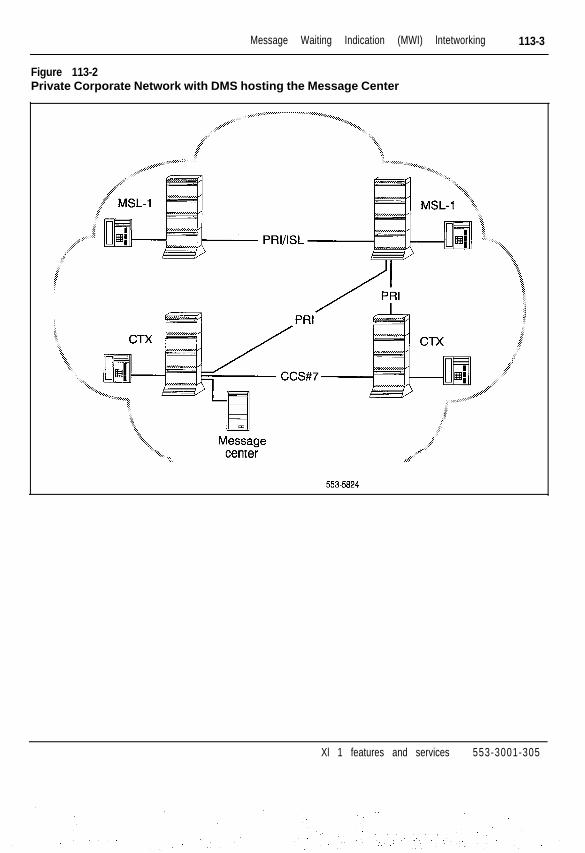
Message Waiting Indication (MWI) lntetworking 113-3
Figure 113-2Private Corporate Network with DMS hosting the Message Center
. : : :‘ - . . : . . _ : :y
5535824
Xl 1 features and services 553-3001-305

113-4 Message Waiting Indication (MWI) Interworking
Operating parametersThe switches in the network are connected as shown in Table 113-1.
Table 113-lNetwork switch connections
To connect Use
Meridian 1 to Meridian 1 ISDN/PRI/ISL
Meridian 1 to other system P R I
Other system to other system PRI/CCS#7
If the Message Center is on a Meridian-l and it serves users on DMS, theMeridian-l must be on X11 release 19 or later.
If the Message Center is on DMS for MWI Interworking, a Meridian-l that isconnected to DMS must be on X11 release 19 or later.
End-to-End Signall ing is required to access the Message Center features froma local or remote system.
Only Meridian Mail is supported for use as the Message Center on a Meridian1. This feature does not support any other messaging system, such as amanual Message Center hosted on a Meridian 1, a non-Meridian producthosting the Message Center, or other server applications (such as FAXservers or E-Mail).
The other system can be a tandem switch. DMS BCS 36 or later supportsDMS-100, DMS-250, and SL-100 systems. Only Northern Telecom systemsare supported.
Xi 1 features and services 553-3001-305
. .

Message Waiting Indication (MWI) lntetworking 113-5
Feature interactions- Multi Customer MWI
Interworking does not support mult iple customers because MeridianMail supports only one customer. If multiple customers are required,multiple Meridian Mail servers are required.
- Multi TenantMeridian Mail Phase 8 and later supports Multi Tenant. For MWIInterworking, tenants that belong to the same customer can use one ormultiple Message Center servers. Tenants from different customerscannot use the same Meridian Mail. The customer can allow (ordisallow) access to this feature for specific tenants by configuring (or notconfiguring) the tenant’s sets for call forwarding to Meridian Mail DN.
- Trunk Optimization Before AnswerThere is no Trunk Optimization when the call is redirected to DMS, oranswered by Meridian Mail . This applies to applicat ions such as AutoAttendant .
- Network Message Services-Meridian MailThe Facil i ty message for MWI Interworking uses a different TransactionCapabilities Application Part (TCAP) format from that used for othernetwork message services. Message conversion occurs when sendingand receiving MWI Facility messages with software earlier than X11release 19.
- DCH Error MonitoringX11 release 17 DCH Error Monitoring monitors ISDN messages on a perfeature basis. The conflict between the Service Identifier used byMeridian 1 and DMS for Network Message Services is resolved byproviding a different Service Identifier (H70). X11 release 19 supportsboth the existing (H7C) and new Service Identifiers.
However, if the MWI RCAP for the D channel is added or deleted inOverlay 17, the D channel message monitoring must be disabled andenabled so that DCH Error Monitoring will work properly for theNetwork Message Services (NMS) feature.
- ISDNIAP Link RecoveryCalls in the Meridian Mail ACD queue are redirected to the ACD NightCall Forward DN when the Application Modular Link (AML) goesd o w n .
X1 1 features and services 553-3001-305
.

113-6 Message Waiting Indication (MWI) Interworking
Feature packagingMWI Interworking is available as package 219. It requires the NetworkMessage Service features of Meridian Mail release 7. It also requires that theother system be equipped with BCS 36 at a minimum. The packagerequirements for each node are described in the following tables.
Table 113-2Package requirements for the originating node (the node with MessageCenter users)
MWI package 219 If connected to DMS (BCS 36) forIn te rwork ing
NMS package 175
BACD package 40 andACDA package 45
ISDN Signal ing package 145
If ACD DN is used as the MessageCen te r DN
ISDN Primary Rate Accesspackage 146 orISDN Signa l ing L ink package 147
ISDN Network Service package148
Message Cen te r (MWC) package4 6
End-to-End Signal ing (EES)package 10
Xl 1 features and services 553-3001-305
,, ,, :. ,). ., .:. -. . . .: _

Message Waiting Indication (MWI) Interworking 113-7
Table 113-3Package requirements for the host node (the node hosting the MessageCenter)
MWI package 219
NMS package 175
Integrated Message System (IMS)package 35
ISDNIAP package 77
BACD package 40
ACDA package 45
ISDN Signal ing package 145
ISDN Primary Rate Accesspackage 146 orISDN Signaling Link package 147
ISDN Network Servicespackage 148
Message Cen te r (MWC)package 46
End- to-End Signal ing (EES)package IO
Xl 1 release 19 or later is required.
Table 113-4Package requirements for the tandem node (the node that does nothave Message Center users)
MWI package 219
ISDN Signal ing package 145
ISDN Primary Rate Accesspackage 146 orISDN Signaling Link package 147
ISDN Network Servicespackage 148
If connected to DMS (BCS 36) forIn te rwork ing
Xi 1 features and services 553-3001-305

113-8 Message Waiting Indication (MWI) Interworking
Feature implementation‘See Figure 113-3 for the configuration required for MWI Interworking.
Figure 113-3Configuration Requirements for MWI Interworking
MSL-1R16, 17,18, or 19
MSL-1RI9
WI
MSL-1Rl9
MC
MSL-1
18, or 19
MSL-1 DMSBCS 36
MSL-1R16, 17,18, or 19
MSL-1 DMSR19 BCS 36
553-5825
Xl 1 features and services 553-3001-305
f

Message Waiting Indication (MWI) Interworking 113-9
Response to the fol lowing prompts in the l is ted overlays act ivates MWIInterworking.
Table 113-5LD 17-Configuring MWI remote D channel capability
R E Q C H G
TYPE C F N
RLS 1 9 Release ID of the switch at the farend of the D channel interface
RCAP M W I Add MWI as a remote D channelcapability; use XMWI to remove thecapability.
Table 113-6LD 23-Configuring a Message Center DN
REQ
TYPE
CUST
A C D N
M W C
Feature operationNot applicable.
N C F W
NEW/CHG
A C D
xx
xxxx
YES
xx.....xx
ACD DN message center DN
DMS message center DN, 1 O-digitpublic number prefixed by an ESNaccess code or an ESN numberprefixed by an ESN access code (ifUniform Dialing Plan (UDP) isused)
Xl 1 features and services 553-3001-305
: I .::.‘.. ‘I

113-10 Message Waiting Indication (MWI) Interworking
Xi 1 features and services 553-3001-305
Issued: 9 2 1 2 3 1S ta tus : Standard
Xi 1 Release: 15 1114-l
Message Waiting Lamp MaintenanceThis maintenance enhancement alleviates the “dark effect” when neon lightsare tested in low ambient light conditions.
Because the dark effect is inherent to neon lamps, it is recommended thatPBXT Message Waiting Lamp tests not be run during low ambient lightconditions. The line card detector circuitry may register lamp failures underthese circumstances, and the Message Waiting Lamp test may be unreliable.Lamps are listed as faulty when they fail the test once in three attempts.
The PBXT Message Wait ing Lamp tests should be run under one of thefollowing conditions:
- automatically at a system specified time
- manually at any time (LD32)
Automatic scheduling should consider low traffic times, when there is stillenough ambient light to avoid the dark affect. To prevent the automaticscheduling of LD32, LD32 must be excluded from the daily routines(“midnights”) and the system defined hour must be the default “X” value.
When the hour defined defaults to the “x” value, an error message is outputto remind the customer that the PBXT tests are s t i l l par t of the dai ly rout ines,unless LD32 is removed from the list.
Operating parametersThere are no feature requirements.
Feature interactionsThere are no feature interactions.
Xl 1 features and services 553-3001-305
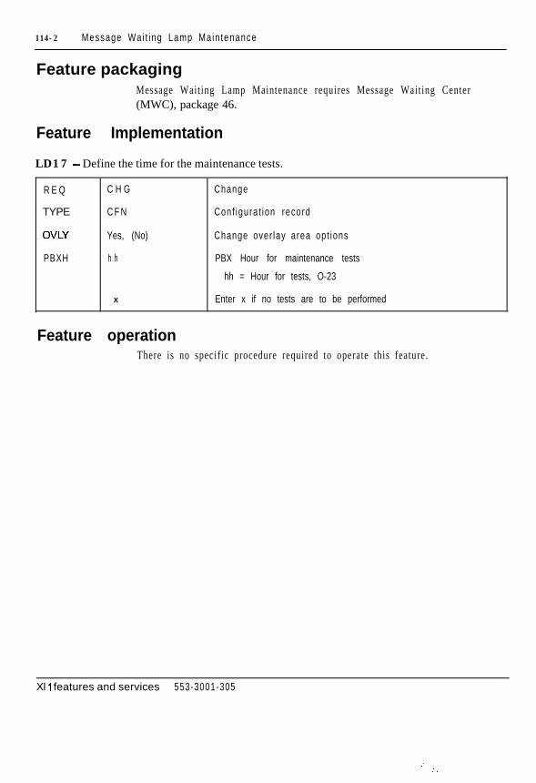
114-2 Message Wa i t i ng Lamp Ma in tenance
Feature packagingMessage Waiting Lamp Maintenance requires Message Waiting Center(MWC), package 46.
Feature Implementation
LD17 - Define the time for the maintenance tests.
R E Q
TYPE
OVLY
PBXH
C H G
C F N
Yes, (No)
h h
X
Change
Conf igura t ion record
Change over lay area opt ions
PBX Hour for maintenance tests
hh = Hour for tests, O-23
Enter x if no tests are to be performed
Feature operationThere is no specific procedure required to operate this feature.
Xl 1 features and services 553-3001-305
.- . - . .

115-1
MSDL Serial Data InterfaceSerial Data Interface (SDI) is supported by the Multi-purpose Serial DataLink (MSDL) card with Xl 1 release 19 and later. SD1 extends the I/Ocapabil i ty of the MSDL card by providing an asynchronous serial datainterface. SD1 is composed of software components that reside on theMeridian 1 and the MSDL.
For a complete description of MDSL SDI, please refer to X1 I systemmanagement application (553-3001-301).
Xl 1 features and services 553-3001-305

115-2 MSDL Serial Data Interface
Xi 1 features and services 553-3001-305
,

Multiple Appearance DN RedirectionPrime
With X 11 release 18 and later, Multiple Appearance DN Redirection Prime(MARP) standardizes call redirection on Multiple Appearance DNs(MADNs) by using a service changeable Multiple Appearance DNRedirection Prime Terminal Number (MARP TN).
Each defined single or multiple appearance DN has only one associatedMARP TN. When a call redirection feature activated against a DN needsTerminal Number (TN)-specific information, the MARP TN is used todetermine feature operation. Call redirection always refers to the MARP TN.
MARP provides consistent operation for the following call redirectionfeatures:
- Call Forward All Calls
Refer to the feature interactions section in this module for importantinformation regarding Call Forward (CFW) operations.
- Call Forward Busy
- Call Forward No Answer
- Hunting
Xl 1 features and services 553-3001-305

116-2 Mul t ip le Appearance DN Red i rec t ion Pr ime
Operating parametersShort Hunt takes precedence over MARP TN directions.
MARP is activated in LD17. If MARP is not active, call redirection occursaccording to the pre-X11 release 18 algorithms. All the MARP prompts andmessages appear even if MARP is not act ive. MARP TNs can st i l l be added,assigned, and changed. Refer to specific call redirection modules in thisdocument for details regarding the pre-X11 release 18 algorithms.
The MARP TN is defined in LDlO or LDll. When activated, only the MARPTN is used to determine call redirection.
If MARP is not activated, the following overlays have this message printed,“MARP NOT ACTIVATED.” The message appears only once, when theoverlay is loaded. When MARP is active, no message appears. The overlaysa r e
LDs 10, 11,20,22,25,80,81,82, and 83
When MARP is activated in service change (MARP = Yes) calls areimmediately directed according to the MARP TN. There is no need tosys load.
Every single or multiple appearance DN has a MARP TN. MARP TNs arealso defined for Data DNs, optional incoming two-way Hot Line DNs, andringing and non-ringing Private Line DNs. Automatic Call Distribution(ACD) DNs are not assigned MARP TNs.
New systems are instal led with MARP act ivated. MARP TNs are assigned toall single and multiple appearance DNs. Call redirection follows the MARPTN ass ignments .
Xl 1 features and services 553-3001-305

Mul t ip le Appearance DN Red i rec t ion Pr ime 116-3
ConversionWhen converting pre-X11 release 18 software to X11 release 18 or later, aMARP TN is automatically assigned for each single and mult iple appearanceDN. This conversion does not activate MARP. Call redirection operatesaccording to the pre-X11 release 18 algorithms. All the MARP prompts andmessages appear even if MARP is not act ive. MARP TNs can st i l l be added,assigned, and changed.
When operating on Xl 1 release 18, and converting to an upissue, the MARPTN assignments remain. If MARP was activated, it retains that activityfollowing the upissue. If MARP was deactivated, that status is alsomaintained following the upissuee.
MARP TNs assigned at service changeEach DN must have an associated MARP TN. After a service change or atelephone relocat ion, the system assigns a MARP TN to the DN in thefol lowing s i tua t ions :
- The MARP TN containing the DN is removed.
- The DN appearance on its MARP TN is changed to another DN.
- The DN appearance on its MARP TN is no longer the redirection prime.
The “TN list” refers to the list of TNs that appears when you print the DNblock in LD20 or LD22 (TYPE = DNB). To determine the order in whichyour TNs appear, print out the DN block.
When ass igning MARP TNs during service change, the system conducts asearch beginning at the top of the TN list for the first appearance of the DNas the Prime DN. The MARP TN is assigned based on the following:
1 The first TN found with a primary appearance of the DN is assigned asthe MARP TN.
2 If no primary appearance of the DN is found, the first TN encounteredwith a secondary appearance of the DN is assigned as the MARP TN.
Xi 1 features and services 553-3001-305

116-4 Mul t ip le Appearance DN Red i rec t ion Pr ime
MARP TNs assigned at conversion and sysloadWhen converting to Xl 1 release 18, a MARP TN is automatically assignedto each DN at sysload. The MARP TNs are assigned to the DNs based on thefollowing:
1 The lowest numerical TN with a primary appearance of the DN isassigned as the MARP TN.
2 If no primary appearance of the DN is found, the lowest numerical TNwith a secondary appearance of the DN is assigned as the MARP TN.
CAUTIONMARP assignments made during conversion may change the mannerin which calls are redirected. Refer to the individual call redirectionmodules in this document for details of the pre-X11 release 18algorithms.
Feature interactionsAttendant AdministrationMARP TNs cannot be added, moved, or deleted with AttendantAdministration. The DN information that displays on the console doesinclude the MARP designation if applicable.
Attendant administration activities, like changing key assignments or DNappearance, may change MARP TN assignments. If so, CSC102 appears onthe teletype (TTY) indicating a new default MARP TN, as follows:
CSC102 DN nnnn NEW MARP 1 s c uW h e r e :
nnnn = the DN associated with the MARP TN1 s c u = the new MARP TN assigned to DN nnnn
Automatic Set Relocation and Modular Telephone RelocationWhen Automatic Set Relocation is used to move a telephone, the telephone’sMARP designations are maintained. During the relocation, a temporaryMARP TN is assigned. The original MARP TN is restored when thetelephone relocates.
Xi 1 features and services 553-3001-305

Mul t ip le Appearance DN Red i rec t ion Pr ime 116-5
When a se t leaves the system due to set relocat ion, the fol lowing CustomerService Change (CSC) message appears:
csc010 x yW h e r e :
x = old TN (I s c u) for the telephoney = ID code entered
The following Service Change (SCH) message appears for any MARP TNreassignment:
SCH5524 DN nnnn NEW MARP 1 s c uW h e r e :
nnnn = the DN associated with the MARP TN1 s c u = the new default MARP for DN nnnn
The History File can be configured to s tore these messages unti l a printout isrequested.
When a telephone reenters the system, the following message appears:
CSCOll x yW h e r e :
x = old TN (1 s c u) for the telephoney = new TN (1 s c u) for the telephone
The following message appears again for each changed TN:
SCH5524 DN nnnn NEW MARP 1 s c uW h e r e :
nnnn = the DN associated with the MARP TN1 s c u = the new MARP TN assigned to DN nnnn
Automatic Call DistributionACD DNs are not assigned MARP TNs. Agent Individual DNs (IDNs) areassigned MARP TNs.
Xl 1 features and services 553-3001-305

116-6 Mul t ip le Appearance DN Red i rec t ion Pr ime
Call Forward All CallsIf CFW is active for a DN, incoming calls are forwarded if a TN is found thathas CFW enabled, and is a single appearance or a Prime multiple appearanceof that DN (according to existing operation). The MARP TN is alwayschecked first to meet these criteria. When the requirements are met, thesystem uses the information associated with the MARP TN to redirect thecall.
If the MARP TN is not a prime appearance but does have CFW enabled, asearch is made for a telephone with a prime appearance of that DN with CFWenabled. When a TN is found, the call is redirected according to the MARPTN’s parameters. If the MARP TN is not a prime appearance and does nothave CFW enabled, the system searches for a prime appearance with CFWenabled. The incoming call is forwarded according to the other telephone’sinstructions (not the MARP TN’s), as shown in Figure 116-1.
Figure 116-lCFW and MARP
T e l e p h o n e A
. C F W3000
,200oM A R P
TeleDhone B
553-5527
C F W3001
CFW .DN on Telephone A is DN 3000.CFW DN on Telephone B is DN 3001.
If only Telephone A has CWF active, calls to DN 2000 are forwarded toDN 3000.
If only Telephone B has CWF active, calls to DN 2000 are forwarded toDN 3001.
If both telephone A and B have CWF enabled, calls to DN 2000 areforwarded to DN 3000 because Telephone A is the MARP TN.
Xi 1 features and services 553-3001-305
. .

Mul t ip le Appearance DN Red i rec t ion Pr ime 116-7
At times, even though the MARP TN is actually a secondary DN appearance,it can control where a call is redirected. Due to potential confusion, it isrecommended that a secondary appearance not be defined as the MARP TNwhen a prime appearance is available. Refer to Figure 116-2.
Figure 116-2MARP control
Telephone AI
.CFW3000
2000
TeleDhone B
CFW DN on Telephone A is DN 3000.CFW DN on Telephone B is DN 3001.
If both Telephone A and Telephone B have CWF active, all calls to DN2000 go to DN 3001 because Telephone B is the MARP TN.
If only Telephone A has CWF active, all calls to DN 2000 go to DN3000.
If only Telephone B has CWF active, no calls to DN 2000 are forwarded.
If all DN appearances are secondary, no calls are forwarded.
Call Forward No AnswerThe MARP TN always controls the call redirection for Call Forward NoAnswer.
HuntingThe MARP TN always controls the call redirection for Hunting. ShortHunting takes precedence over Hunting and MARP. The MARP TN isreferred to unt i l short hunt ing is encountered. Short hunt ing is in control unt i lit expires. When short hunting expires, the MARP TN for the first DN in theshort hunt sequence takes control .
Xi 1 features and services 553-3001-305
:..-: .’

116-8 Mul t ip le Appearance DN Red i rec t ion Pr ime
Feature packagingThis feature is included in the base X11 system software.
Feature implementationIf MARP is not activated, the following overlays have this message printed,“MARP NOT ACTIVATED.” The message appears only once, at the verybeginning of the overlay. When MARP is active, no message appears. Theoverlays are
LDs 10, 11, 20, 22, 2.5, 80, 81, 82, and 83
When changing or adding a new Single Appearance DN to the system, theMARP TN is automatically assigned. The system indicates this TN is theMARP for the new DN with a MARP message.
When adding or changing a Multiple Appearance DN, the system indicateswhich TN is the current MARP TN. You can reassign the MARP TN ifrequired.
SCH5524 appears at the end of the service change session, when the MARPTN has been changed.
LDlO - Add a 500/2500 telephone with a Single Appearance DN.
R E Q
TYPE
T N
D N
-MARP
N E W
500
l s c u
xxx...x
Add new data to the system
50012500 set
Termina l number
D i rec to ry number
MARP prints on the next line indicating this TN is the MARPfor DN xxxx
Xi 1 features and services 553-3001-305
: .

Mul t ip le Appearance DN Red i rec t ion Pr ime 116-9
LDlO -Add a 500/2500 telephone with a Multiple Appearance DN.
R E Q
TYPE
T N
DN
-MARP ON TN
-MARP
SCH.5524 DN nnnn NEW MARP
N E W
5 0 0
l s c u
xxx...x
l s c u
Yes, (No)
l s c u
Add new data to the system
50012500 set
Termina l number
D i rec to ry number
MARP ON TN Is c u prints on the next lineindicating TNI s c u is the current MARP
Set the MARP to this new TN
This message indicates the MARP for the oldDN nnnn is changed. The new MARP isTN I s c u.
LDlO - Changing a 500/2500 telephone with a Multiple Appearance DN.
R E Q
TYPE
T N
D N
-MARP ON TN
-MARP
SCH5524 DN nnnn NEW MARP
C H G
5 0 0
l s c u
xxx. . .x
l s c u
Yes, (No)
l s c u
Modify existing data
5OOl2500 set
Termina l number
D i rec to ry number
This message indicates the current MARP isTNlscu.
Set the MARP to this TN
The message indicates the MARP for the oldDN nnnn is changed. The new MARP isTN I s c u.
Xl 1 features and services 553-3001-305

116-l 0 Mul t ip le Appearance DN Red i rec t ion Pr ime
LDll -Add a telephone with a Single Appearance DN.
R E Q N E W
TYPE aaaa
Add new data to the system
Telephone typeaaaa = SLl ,2006,2008,2009,2016,2018,2112,2216,2317, 2616,300O
TN m_ lscu
KEY xx aaa YYYY
Termina l number
xx is the key number
aaa is the DN type:mcn (multi-call nonring)mcr (multi-call ring)scn (single-call nonring)scr (single-call ring)
yyyy is the DN
-MARP MARP prints on the next line indicating this TN is the MARPfor DN yyyy
KEY Reprompts until <cr> is entered
Xl 1 features and services 553-3001-305

Mul t ip le Appearance DN Red i rec t ion Pr ime 116-l 1
LDll - Add a telephone with a multiple appearance DN.
REQ
TYPE
;-T N
KEY
N E W Add new data to the system
aaaa Telephone typeaaaa = SLI, 2006,2008,2009,2016,2018,2112,2216,2317,2616,3000
l s c u Termina l number
xx aaa YYYY xx is the key number
aaa is the DN type:men (multi-call nonring)mcr (multi-call ring)scn (single-call nonring)scr (single-call ring)
yyyy is an existing DN
-MARP ON TN l s c u MARP ON TN I s c u prints on the next lineindicating TNI s c u is the current MARP
-MARP Yes, (No) Set the MARP to this new TN
KEY Reprompts until <cr> is entered
SCH5524 DN nnnn NEW MARP I s c u This message indicates the MARP for theold DN nnnn is changed. The new MARP isTNlscu.
Xi 1 features and services 553-3001-305

116-l 2 Mul t ip le Appearance DN Red i rec t ion Pr ime
LDll - Changing a telephone with a Multiple Appearance DN.
R E Q
TYPE
T N
KEY
-MARP ON TN
-MARP
KEY
SCH5524 DN nnnn NEW MARP
C H G
a a a a
l s c u
xx aaa YYYY
lscu
Yes, (No)
lscu
LDlO/LDll -Removing a MARP TN.
R E Q
TYPE
T N
SCH5524 DN nnnn NEW MARP
O U T
aaaa
l s c u
l s c u
Modify existing data
Te lephone typeaaaa = SLI , 2006,2008,2009, 2016,2018,2112,2216,2317,2616,3000
Termina l number
xx is the key number
aaa is the DN type:men (multi-call nonring)mcr (multi-call ring)scn (single-call nonring)scr (single-call ring)
yyyy is the DN
MARP ON TN Is c u prints on the next lineindicating TNI s c u is the current MARP
Set the MARP to the working TN
Reprompts until <cr> is entered
This message indicates the MARP for theold DN nnnn is changed. The new MARP isTNlscu.
Remove data from the system
Telephone typeaaaa = 500,2500, SLl ,2006,2008,2009,2016,2018,2112,2216,2317,2616,3000
TN I s c u is the MARP for DN nnnn.This is the TN that is being removed.
This message indicates the MARP for theold DN nnnn is changed. The new MARP isTNlscu.
Xl 1 features and services 553-3001-305

Mul t ip le Appearance DN Red i rec t ion Pr ime 116-13
LD17 - Activat ing or deact ivat ing MARP.
R E Q C H G Change da ta
TYPE C F N Conf igura t ion record
PARM YES Change sys tem paramete rs
?.4ARP YES/NO Activate or deactivate MARP There is no default. <CR>retains the previous system data.
LD20 or LD22 - Print MARP information.
R E Q P R T
TYPE TNB (DNB, SLI)
Print information
Terminal number data block
(Can also print out DN data block or telephone type.)
The printout will look like the following.
- For the DN datablock:
DN 2000TYPE SLlTN 018 0 02 00 KEY 00 MARP DES NO DES NO DATETN 018 0 02 01 KEY 01 DES NO DES NO DATE
- For a telephone data block:
DES NO DESTN 0010 0 00TYPE SLlKEY 00 MCR 2000 MARP01 MRK
Feature operationNot applicable.
Xl 1 features and services 553-3001-305
,...

116-14 Mul t ip le Appearance DN Red i rec t ion Pr ime
Xl 1 features and services 553-3001-305

Multiple Console operationThe Meridian 1 permits each customer to have up to 63 attendant consoles.X 11 release 7 and earlier software permit each customer to have up to 15attendant consoles. Incoming calls are routed in a circular fashion to the firstidle attendant. If al l consoles are busy, calls are held in the attendant queueand are presented to the f i rs t idle at tendant . Each console is identif ied by acustomer-defined, two-digit attendant console number (01 to 63).
The assignment of Incoming Call Indicators (ICIs) and Trunk Group Busy(TGB) key/lamp pairs is identical for all attendant consoles in the customergroup, except when Console Presentation Group Level Services, amulti-tenant feature, is configured. The flexible features key/lamp strip canbe assigned on a per console basis .
The features that can be assigned to the flexible features str ip include thefollowing:
- Attendant Administration
- Autodial
- Automatic Wake Up
- Barge-In
- Busy Verify
- Call Park
- Calling Party Number
- Charge Account
- Controlled Class of Service, Enhanced
- Display Calls Waiting
Xl 1 features and services 553-3001-305
:..

117-2 Mul t ip le Conso le opera t ion
- Display Date
- Display/Change Date
- Display Destination
- Display Source
- Display Time
- Display/Change Time
- Do Not Disturb (Individual)
- Do Not Disturb (Group)
- End to End Signaling
- Malicious Call Trace
- Message Cancellation
- Message Indication
- Mini-CDR Low Tape Alarm (SL-1M only)
- Paging
- Routing Control
- Speed Call Controller
- System Speed Call Controller
- Stored Number Redial
Operating parametersPrior to X11 release 8, only 15 attendant consoles per customer werepermitted. X11 release 8 and later software allows 63 consoles to be definedper customer.
Feature interactions- Departmental Listed Directory Number (DLDN)
DLDN supports the assignment of 63 consoles per Departmental LDN.
- Multi-Tenant ServicesUp to 63 consoles may be defined in a s ingle Console Presentat ion Group(CPG).
Xi 1 features and services 553-3001-305

Mul t ip le Conso le opera t ion 117-3
Feature packagingThis capability is included in basic X11 system software.
Feature implementationThe following overlays have been modified to allow input of 63 consoles onX11 release 8 and later software:
- Attendant Console LD12- Customer Data Block LD15- Tenant-to-Tenant Access LD93
Feature operationThere is no specific procedure required to operate this feature.
Xi 1 features and services 553-3001-305
.; ”
, .: _

117-4 Mul t ip le Conso le opera t ion
Xi 1 features and services 553-3001-305
,.: : : ... . .

Multiple Customer OperationThe Meridian 1 system can serve up to 32 (customer numbers O-3 1)individual customers from the same machine. X1 1 release 14 and latersoftware supports 100 customer groups (numbered O-99). Customers havetheir own features, restrict ions, numbering plans, trunks, and special services.They are granted access to the system as if they are the sole user.
Operating parametersOnly XN, NT, XT, 6 1, 7 1, and 8 1 systems on Xl 1 release 14 and latersoftware can implement 100 customer groups.
Feature interactionsSystem hardware, like serial data interface (SDI), Digitone Receiver (DTR),Tone and Digit Switch (TDS), and Conference, are shared among all thecustomers on the machine.
The Speed Call list parameter (8 19 1) applies to the machine, not thecustomer. I t is shared among all customers on the sys tem.
Feature packagingMultiple Customer Operation (CUST), package 2, has no feature packagedependencies.
Feature implementationNot applicable.
Xl 1 features and services 553-3001-305

118-2 Mul t ip le Cus tomer Opera t ion
Xi 1 features and services 553-3001-305
-.
I ssued: 92 12 31Sta tus : StandardX1 1 Release: Al l 1
119-l
Multi-Tenant ServiceThe Multi-Tenant Service feature facilitates the resale by Meridian Icustomers of Meridian 1 services and resources. Telephones belonging to acustomer may be divided into customer sub-groups known as tenants. Thegroups are separated by group access restrictions. Access to other tenants, toattendant consoles, and to trunk routes can be programmed in such a way thattenants can have private use of some facilities, share some, or be deniedaccess to others. Call Detail Recording (CDR) records include the tenantnumber as well as the customer number.
The number of tenants that can be configured per customer depends on thenumber of configured customers and the amount of available memory. Themaximum is 5 12 tenants per customer. All telephones default to Tenant 0(zero).
All tenants share the customer’s numbering plan and service-changeablefeatures. Because the features are defined at the customer level, they areidentical for each tenant. Possible features are outlined in the followingparagraphs.
- Tenant-to-Tenant AccessA tenant’s relat ionship with other tenants of the same customer is definedby Tenant-to-Tenant Access. A tenant can be configured to allow directinternal call access to some or all tenants of the same customer. Likewise,the tenant can be denied direct access to other tenants. To reach thesetenants, a trunk call must be placed.
Xl 1 features and services 553-3001-305
I.

119-2 Mul t i -Tenan t Se rv i ce
- Tenant-to-Route AccessMeridian 1 supports up to 128 trunk routes per customer. XN, NT, XT,61,71, and 81 systems support 512 trunk routes per customer on X11release 14 and later software. Each tenant can share or have privateaccess to any or all of these routes. Tenant access applies only tooutgoing calls . All tenants have access to incoming calls on any route.
- Attendant Console GroupsWithin the Multi-Tenant Service feature, al l at tendant consoles areplaced into groups that are associated with specific tenants and specificincoming trunk routes. The group number range is from zero through 63.All attendant consoles configured for a customer are automaticallymembers of group zero. The other groups are defined in service changeto f i t tenant requirements .
The Multi-Tenant feature functions as fol lows:
- Internal Attendant DN CallsWhen a tenant telephone dials the attendant DN, the call is presented toan idle at tendant console. The call is routed to an at tendant groupassociated with the tenant of the cal l ing telephone, i f at tendant consolegroups attendant console group number (AGNO) have been specified forthe tenant .
- Incoming External CallsIncoming external calls are presented only to the at tendant console groupspecif ied to serve the trunk group.
- Attendant Initiated CallsAll at tendants have access to the customer’s numbering plan and canini t ia te cal ls to any customer’s tenants .
- Attendant Overflow PositionThe Attendant Overflow DN (AODN) is accessible to all tenants onincoming trunk cal ls . Attendant cal ls from tenants who do not havetenant access to the AODN do not divert to AODN but remain in theattendant queue.
- Attendant RecallWhen a tenant telephone recalls the attendant, the call is presented to anattendant in a group specified for the tenant of the call ing telephone.
Xl 1 features and services 553-3001-305

Mul t i -Tenan t Se rv i ce 119-3
- Attendant Extended CallInternal at tendant calls from tenant A to tenant B may be extended onlyif tenant A and tenant B are allowed Tenant-to-Tenant Access.
- Access to Incoming Trunk RouteAny tenant can be accessed on an incoming call from any incoming trunkroute. Attendant console groups can be specified to receive automaticpresentat ion of incoming cal ls from specif ied routes. This includes cal lsthat terminate at an at tendant console and calls that intercept to anattendant console.
- Access to Outgoing Trunk RoutesTenants dial the appropriate trunk route access code to connect to a trunkroute. Access codes are assigned on a trunk route basis. Therefore alltenants use the same access code to connect to a particular route.Customer telephones have access to al l outgoing trunk routes belongingto their tenants. Access to specific trunk routes is al lowed or denied toindividual tenants through service changes. Tenants who try to accessdenied routes receive normal intercept treatment.
Operating parametersRefer to Multi-Tenant Service description (553-2831-100).
Feature interactionsMulti-Tenant access restr ict ions affect the way that tenants interact with othertenants, t runk routes, and at tendant consoles.
In general, Multi-Tenant access restrictions take precedence over theMeridian 1 features with which they interact.
Feature packagingMulti-Tenant Service (TENS), package 86, has no feature packagedependencies.
Xl 1 features and services 553-3001-305

119-4 Mu l t i -Tenan t Se rv i ce
Feature implementation
LD93-Enable, disable, or print Multi-Tenant Service for a specified customer.
REQ NEW, OUT, PRT
T Y P E T E N S Tenant service data block
CUST o-99 Cus tomer number
I Note: Ensure that the customer night DN and the attendant overflow DN (if assigned) are accessible by alltenants
LD93-Allow, deny, or print tenant-to-tenant access for a specified tenant.
R E Q
TYPE
C U S T
T E N
A C C
D E N Y
ALOW
C H G , P R T
T A C C
o-99
l-511
D E N Y
ALOW
l-511 l-51 1
ALL
l-511 l-51 1
ALL
Change or pr in t
Tenant-to-tenant access data block
Cus tomer number
Tenant number
Access denied tenants are to be entered
Access allowed tenants are to be entered
Tenant numbers denied access to and from this tenant(p rompted i f ACC=DENY)
All tenant numbers denied access to and from this tenant(tenant can only access itself)
Tenant numbers allowed access to and from this tenant(p rompted i f ACC=ALOW)
All tenant numbers allowed access to and from this tenant
Note: Tenant 0 is reserved for telephones with a TEND Class of Service 1
Xl 1 features and services 553-3001-305

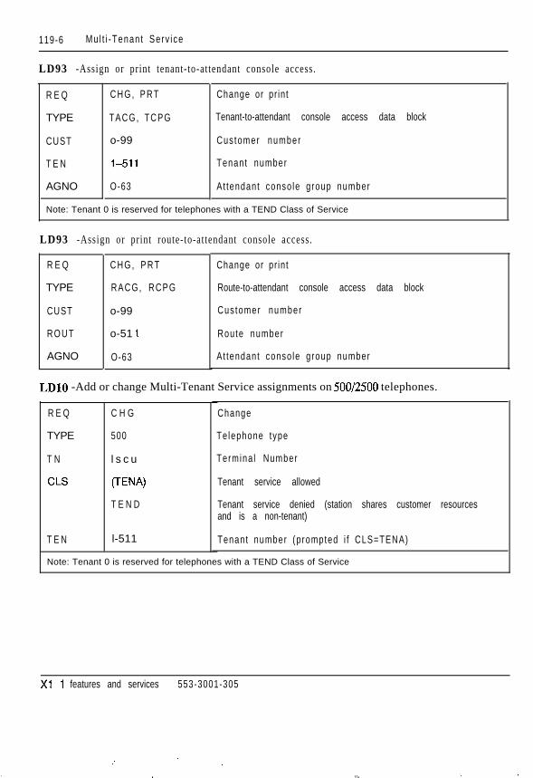
119-6 Mu l t i -Tenan t Se rv i ce
LD93 -Assign or print tenant-to-at tendant console access.
R E Q
TYPE
CUST
T E N
AGNO
C H G , P R T
TACG, TCPG
o-99
l-51 1
O-63
Change or pr in t
Tenant-to-attendant console access data block
Cus tomer number
Tenant number
At tendant conso le group number
Note: Tenant 0 is reserved for telephones with a TEND Class of Service
LD93 -Assign or print route-to-at tendant console access.
R E Q
TYPE
CUST
R O U T
AGNO
C H G , P R T
RACG, RCPG
o-99
o-51 1
O-63
Change or pr in t
Route-to-attendant console access data block
Cus tomer number
Route number
At tendant conso le group number
LDlO -Add or change Multi-Tenant Service assignments on 500/2500 telephones.
R E Q
TYPE
T N
CLS
T E N
C H G
500
l s c u
CTEW
T E N D
l-511
Change
Te lephone type
Termina l Number
Tenant service allowed
Tenant service denied (station shares customer resourcesand is a non-tenant)
Tenant number (p rompted i f CLS=TENA)
Note: Tenant 0 is reserved for telephones with a TEND Class of Service
Xl 1 features and services 553-3001-305
: ; . . .
. l._ ,. __


119-8 Mul t i -Tenan t Se rv i ce
Xi 1 features and services 553-3001-305
: .

Issued:S ta tus :Xl 1 Release:
120-I
Multi-User LoginMeridian-l Multi-User Login (MULTI-USER) (package 242) enables up tothree users to log in, load, and execute overlays simultaneously. These threeusers are in addit ion to an attendant console or maintenance terminal. TheMulti-User Login capability increases the efficiency of craftspersons byenabling them to perform tasks in parallel.
For a complete description of Multi-User Login, please refer to Xl 1 systemmanagement application (553-3001-301).
Xl 1 features and services 553-3001-305

120-2 Mul t i -User Login
Xl 1 features and services 553-3001-305


121-2 M u s i c
When a Universal trunk card is used, Music and RAN trunks can be assignedto the same card.
Connections blocked once are not automatical ly at tempted again.
Simple source-only connections on the at tendant console receive music; al lo thers do not .
Main Release Link Trunks do not receive music.
Calls to special trunks (such as Paging or Dictation) do not receive music ifplaced on hold.
The music trunk Terminal Number (TN) must be within the same networkgroup as the conference circuit to which i t is assigned.
One music trunk per customer must be located in each network grouprequiring music.
Music is not supplied across groups ( i f group 4 does not have a music t runkand groups O-3 have music trunks, then an incoming call to group 4 placed onhold will not receive music).
A single conference loop with one music trunk assigned can support up to 29simul taneous l i s teners .
If more than one music trunk is assigned to one conference loop, they mustuse different routes. The total number of possible listeners is 30 minus thenumber of assigned trunks. Addit ional music trunks and conference loops canbe configured if required.
The music source must be compatible with the music trunk circuit pack.
Xi 1 features and services 553-3001-305

M u s i c 121-3
Feature interactions
- Attendant Trunk Group Busy Indicat ionA music route that appears on a Trunk Group Busy key on the at tendantconsole cannot be control led by act ivat ion of the Trunk Group Busy key.In addition, the associated lamp will not reflect the status of the musictrunks .
- ConferenceWith enhanced music on hold, when a cal l is placed on consultat ion holdwhile a conference is being established, music plays. Once theconference is established, music no longer plays. If the call returns to atwo-party call, music plays whenever the call is held.
With basic music on hold. when a cal l is placed on consultat ion holdwhile a conference is being established, music does not play.
- Call ParkWhen a call is parked, music is not heard. When a trunk is parked, musicplays if music is enabled for the route.
Feature packagingMusic (MUS), package 44, requires:
- Recorded Announcement (RAN), package 7
Music on DelayMusic on Delay presents a l is ten-only path to a music source for cal ls wait ingin ACD queues. Music on Delay sources are identified separately for eachAutomatic Call Distribution Directory Number (ACD DN). Complete detailsare described in Automatic Cal l Dis tr ibut ion advanced features descr ipt ion(553-2671-101).
Xl 1 features and services 553-3001-305

121-4 M u s i c
Feature implementation
LD17 - Add or change conference loops for Music on Hold.
R E Q
TYPE
CEQU
XCT
C O N F
C H G
C F N
Yes, (No)
O-158
O-158
Change
Conf igura t ion record
Change to CE parameters
Loop number for NT8D17 ConferencenDS/MFS card.Enter an even network loop number for TDS/MFS functions.The conference function is automatically assigned the nexthigher (odd) loop number.
Loop number for conference card
LD16 - Add or change a music route.
R E Q
TYPE
CUST
TKTP
ICOG
ACOD
Note: All
C H G
R D B
0799
M U S
OGT
XXXX
Change
Route data block
Cus tomer number
M u s i c r o u t e
Outgo ing route on ly
Trunk route access code
er prompts can be set to default values.
LD14 - Add or change a music trunk.
R E Q
TYPE
T N
CUST
R T M B
CFLP
N E W , C H G
M U S
l s c u
o-99
xxx YYY
O-158
New or change
Music trunk
Termina l number
Cus tomer number
Route number and member number
Conference loop assigned to music in LD17
Xi 1 features and services 553-3001-305


121-6 M u s i c
Xl 1 features and services 553-3001-305
.
:. -: .’
-- .., .‘,l,“... : 7; .‘.,,,. . . . . ‘... .- _:.’ ..:. ,,’

Issued: 92 12 31Status: StandardXl 1 Release: 1 2
122-1
Music, EnhancedEnhanced Music (EMUS) provides music for internal and external calls.Music is provided when telephones are placed on Hold, Consultat ion Hold,and Camp-On and when calls at the at tendant console are spli t using the“Exclude Source/Destination” keys.
Enhanced Music (EMUS) provides music in situations described inTable 122-1.
Table 122-lFeatures vs. No Music, Music, and Enhanced Music
Without Music Music Only
Sets Trunks Sets Trunks
ROA Wai t ing N o N o Yes Yes
Call Park N o N o Yes Yes
A C D M u s i c N o N o Yes Yes
Hold Key N o N o N o Yes
Permanent Ho ld N o N o N o Yes
Consu l ta t ion Ho ld N o N o N o Yes
Spl i t t ing N o N o N o Yes
Camp-On N o N o N/A Yes
Enhanced Music
Sets Trunks
Yes Yes
Yes Yes
Yes Yes
Yes Yes
Yes Yes
Yes Yes
Yes Yes
N/A Yes
Xl 1 features and services 553-3001-305

122-2
OPe
Feal


122-4 Mus ic , Enhanced
Feature implementation
LD17 -Add or change conference loops for Music on Hold.
R E Q C H G
TYPE C F N
CEQU Yes, (No)
XCT O-l 58
C O N F 8-l 58
Change
Conf igura t ion record
Change to CE parameters
Loop number for NTBDI 7 ConferencerfDS/MFS card.Enter an even network loop number for TDS/MFS functions.The conference function is automatically assigned the nexthigher (odd) loop number.
Loop number for conference card (must be an evennumbered loop)
LD15 - Enable/disable Music for a customer.
R E Q
TYPE
CUST
M U S
MUSR
C H G
C D B
o-99
Yes, (No)
o-51 1
Change
Customer data block
Cus tomer number
Enhanced mus ic fo r te lephones
Music route for telephones
LD16 - Add or change a music route.
R E Q
TYPE
C U S T
T K T P
~ ICOG
N E W , C H G
R D B
o-99
M U S
OGT
ACOD XxXx
1 Note: All other prompts can be set to
New or change
Rout data block
Cus tomer number
M u s i c r o u t e
Outgo ing route on ly
Trunk route access code
lefault values.
Xi 1 features and services 553-3001-305


122-6 Mus ic , Enhanced
Xi 1 features and services 553-3001-305
,

Network Message ServicesThe Network Message Services (NMS) uses signaling capabilities from theIntegrated Services Digital Network (ISDN) to provide messaging servicesover a network link. Networks with Primary Rate Interfaces (PRI) orIntegrated Services Links (ISL) can extend exist ing message services to userssupported by that network, on a customer basis. Access to the NetworkMessage Services (NMS), and feature activation from the messaging system,is transparent to the end user.
Network Message Services (NMS) is composed of two dist inct applicat ions:NMS-Message Center (NMS-MC) and NMS-Meridian Mail (NMS-MM).
Network Message Services-Message Center (NMS-MC)With Xl 1 release 15 and later, NMS-MC provides centralized MessageCenters for switches on ISDN Primary Rate Interface (PRI) and IntegratedServices Link (EL) networks. This feature carries the networking capabili t iesfor a caller to access the Message Center attendant or Automatic CallDistribution (ACD) agent. The NMS-MC provides two types of functionsover the ISDN PRI/ISL network:
- Message Center Access
- message waiting indication
Three types of Message Centers are supported:
- Automatic Call Distribution (ACD) Message Centers
- DN-type Message Centers
- Attendant Message Centers
Xi 1 features and services 553-3001-305
. . :.

123-2


123-4 Network Message Serv ices
Xl 1 features and services 553-3001-305


124-2 New Flexible Code Restriction
Operating parametersNew Flexible Code Restriction (NFCR) can be programmed to count thenumber of digits dialed and deny any call exceeding the specified number ofd ig i t s .
Only the digits zero through nine are considered. If a user dials an asterisk (*),i t is not counted as a dialed digit . If the user dials an octothorpe (#) beforeNFCR has finished digit counting, the call is disallowed and the appropriateintercept treatment is provided. This prevents digits from 2500-typetelephones or dual tone mult ifrequency (DTMF) trunks from being outpulsedbefore being counted or analyzed by code restriction.
As many as 255 code restriction trees are available per customer. Eight coderestriction trees can be referenced by each trunk route.
Up to 50 digits can be analyzed by NFCR.
When Code Restriction (LD19) and NFCR (LD49) are both enabled for thesame customer, NFCR takes precedence. Any parameters required for CodeRestriction are ignored.
Feature interactions- Authorization Code
If the class of service of the authorization code is Toll Denied (TLD),NFCR is applied. If the class of service is Conditionally Unrestrictedclass of service (CUN) or Conditionally Toll Denied (CTD) and the callis not routed through BARSmARS, CDP or ANI, NFCR is applied.
- Automatic Number Identification (ANI)Calls from Toll Denied (TLD) stations routed by AN1 are subject toNFCR. Calls placed by Conditionally Toll Denied (CTD) andConditionally Unrestricted class of service (CUN) stations subject toAN1 are treated as unrestricted calls.
- BARS/NARS/CDPOnly TLD telephones are subject to NFCR when calls are routed byBARS/NARS/CDP. CTD and CUN calls routed by BARS/NARS/CDPare not subject to NFCR treatment.
Xl 1 features and services 553-3001-305
_:::

New Flexible Code Restriction 124-3
- Direct Inward System Access (DISA)If the DISA DN has a TLD, CUN or CTD class of service, calls madethrough DISA are eligible for NFCR treatment.
- Forced Charge AccountCalls placed through the Forced Charge Account feature are not el igiblefor NFCR treatment.
- Network Class of Service (NCOS)Toll Denied s tat ions and t runks must have an NCOS assigned to beallowed or denied calling privileges by NFCR. This is because the FRLassociated with the NCOS of the user determines which codes areallowed or denied on an outgoing trunk call . The range of NCOS groupsvaries as follows:
(Ob3 for standalone CDP(0)-7 for BARS/CDP and NFCR(0)-15 for NARS and NFCR(0)-99 for BARS/NARS/CDP/NFCR in Xl 1 release 13 and latersoftware
Feature packagingNFCR, package 49, requires:
- Network Class of Service (NCOS), package 32
Xl 1 features and services 553-3001-305
;. ‘.,..,. :.- .‘_

124-4
Fea
LDlS
R E Q
TYPI
c u s
N F C
MAX
L D 8 7
R E Q


124-6 New Flexible Code Restriction
LDlO - Assign a 500/2500 telephone a Toll Denied and Network Class of Service.
R E Q C H G Change
TYPE 5 0 0 Telephone type
a
Termina l Number
NCOS
Toll Denied class of service
t,-. iT N
NCOS
CLS
lscu
(O)-99
T L D
LDll -Assign SL-1 and digital telephones a Toll Denied and Network Class of Service.
R E Q
TYPE
T N
NCOS
C L S
C H G
aaaa
l s c u
(O)-99
T L D
Change
Te lephone type
aaaa = SLI, 2006,2008,2009,2016,2018,2112,22f6,2317, 2616, 3000
Termina l Number
NCOS
Toll Denied class of service
LDl -Assign a trunk a Toll Denied and Network Class of Service.
I R E Q C H G Change
TYPE
T N
NCOS
I CLS
aaa
l s c u
(O)-99
T L D
Trunk type
aaa = CSA, TIE, WAT
Termina l Number
NCOS
Toll Denied class of service
Xl 1 features and services 553-3001-305


124-B New Flexible Code Restriction
Xi 1 features and services 553-3001-305

Night Key for DID Digit ManipulationThe Night Key for DID Digit Manipulation (NKDM) uses DID IncomingDigit Conversion (IDC) to convert received DID digits into Night ServiceDirectory Number (DN). NKDM is used to switch between a Night and Daymodes .
The Day/Night mode is controlled by a DID Route Control (DRC) key on anattendant console, SL-1 telephone, or digital telephone. There can only be oneDRC key for each DID route.
The Night tree table is invoked in any of the following ways:
- when the at tendant goes into Night Service, or the last at tendant activatesthe POS BUSY key (provided that Attendant Overflow Position (AOP)is not equipped)
- when an attendant activates the DID Route Control (DRC) key
- when a Console Presentation Group (CPD) attendant goes into NightService
- when an SL-1 or digital telephone activates the DRC key
In each case, only the DID routes controlled by the ini t iat ing source (consoleor telephone) are affected.
Xl 1 features and services 553-3001-305

125-2
OP&


125-4 Night Key for DID Digit Manipulation
LD16 - Set IDC tree for Night mode. Note that a DID route cannot be removed if it is controlledby a DCR key.
R E Q
TYPE
T K T P ,-
I D C
D C N O
N D N O
C H G
R D B
D I D
Yes, (No)
O-254
O-254
< C R >
Change
Route Data Block
DID route
Enab le IDC
IDC tree for Day mode
IDC tree for Night mode
Set tree to the same number as Day mode (default)
LD12 - Define a DID Route Control key (DRC) on an attendant console.
REQ C H G Change
TYPE ATT, 1250,225O Conso le t ype
T N l s c u Termina l Number
KEY xx DRC yyy D R C
xx = key number O-9 (O-l 9 on M2250)
yyy = route number (O-51 1)
LDll -Define a DRC key on an SL-1 or Meridian digital telephone.
R E Q
TYPE
T N
KEY
C H G
aaaa
l s c u
xx DRC yyy
Change
Te lephone type
aaaa = SLl ,2006,2008,2009,2016,2018,2112,2216,2317,2616,3000
Termina l Number
D R C
xx = key number
yyy = route number (O-51 1)
Xl 1 features and services 553-3001-305


125-6 Night Key for DID Digit Manipulation
Xi 1 features and services 553-3001-305

Night ServiceNight Service permits incoming cal ls normally directed to the at tendant to berouted to a defined destination. A separate Night key/lamp pair allows theattendant to put the system into Night Service.
Three types of Night Service are provided the customer can specifyseparately or in any combination:
- Selected Trunks to Selected Directory Number (DNs): Some or all of thetrunks can be assigned to r ing selected DNs when the system is in NightService. The assignment of t runks to stat ions can be modified by theattendant or by a service change.
- Night Answer Telephone: All calls normally routed to the attendantconsole can be routed to one part icular DN that is designated as the nightanswer destination for the customer. Trunk Answer From Any Station(TAFAS) can be used to pick up cal ls routed to this number.
- TAFAS: Incoming calls activate a common alerting device, such as abell, when the system is in Night Service. Any user can answer the callby dialing the Special Prefix (SPRE) code and then pressing 4.
- Night Service by Time of Day (NSTD): Available in Xl 1 release 12 andlater, NSTD allows one of a group of Directory Numbers (DNs) to beselected for call routing based on the t ime of day instead of al l cal ls beingrouted to a fixed Night Service DN. NSTD allows the definition of up tofour Night DNs with a time associated with each. Calls are forwarded tothe appropriate DN by the associated t ime.
Xl 1 features and services 553-3001-305

126-
OP


1 2 6 - 4 Night Service
Feature packagingNight Service is included in basic X11 system software.
Feature implementation
LD15 Txdd or change Night Service for a customer.
R E Q
TYPE
CUST
NITE
NIT1
TIM1
N I T 2
TIM2
N I T 3
TIM3
N I T 4
TIM4
Note: Night Service DN times must be defined in ascending order.
C H G
C D B
o-99
xxx...x, x
xxx...x, x
O - 2 3 O - 5 9
xxx...x, x
O - 2 3 O - 5 9
xxx...x, x
O - 2 3 O - 5 9
x x x . . . x , x
O-23 O - 5 9
Change
Cus tomer Da ta B lock
Cus tomer number
Night Service DN (prior to Xl 1 release 12 only)
Night Service DN 1 (enter X to remove)
DN 1 time (hour and minute)
Night Service DN 2 (enter X to remove)
DN 2 time (hour and minute)
Night Service DN 3 (enter X to remove)
DN 3 time (hour and minute)
Night Service DN 4 (enter X to remove)
DN 4 time (hour and minute)
LDl&Add or change Night Service DN for trunks.
R E Q C H G Change
TYPE C O T Trunk type
T N l s c u Termina l Number
NITE xxx...x, x Night Service DN for this trunk (enter X to remove)
Xl 1 features and services 553-3001-305
.


126-6 Night Service
Xl 1 features and services 553-3001-305

Issued:Status:Xl 1 Release:
127-1
No Hold ConferenceCombined with Conference, Speed Call, System Speed Call, Autodial, andHotline, No Hold Conference (NHC) allows you to establish a Conferencecall without placing the current caller on hold.
This feature is available in four forms, merging No Hold Conference (NHC)with Autodial, Speed Call, and Hotline into single key. The new combinedkeys are the Conference-Autodial (CA), Conference-Speed Call (CS), andConference-Hotline (CH) feature keys. A No Hold Conference (NHC) keycan also be configured, acting as a simple conference key.
Conference-Hotline can be used in the following two ways:
- The Direct CH option has the number stored with the key.
- The List CH option has a pointer that selects an entry from a Hotl ine l is t .
When a telephone is connected to another party, you can originate aConference-Autodial (CA), Conference-Speed Call (CS), orConference-Hotline (CH) call by pressing the CA, CS, CH, or NHC key. Thesystem determines the dest inat ion as i f i t were a regular Autodial , Speed Call ,or Hotline call. The parties are conferenced in without holding.
For example, a call comes in to the customer notifying the customer of a fire.The user wishes to notify the fire department of the emergency withoutplacing the original caller on hold, and the number is stored on theConference-Autodial key. By pressing the CA key, the customer establishesa conference call. The fire department is notified and the original connectionis maintained.
Xl 1 features and services 553-3001-305
:

127,-


127-4 No Ho ld Con fe rence
Feature packagingNo Hold Conference capability is available when the following features areequipped:
- Autodial (ADL) for CA key configuration
- Speed Call User (SCU) if the CS key is configured
- Enhanced Hotline (EHOT) for the CH key (package 70)
- System Speed Call to configure CS or CH keys (package 34)
Xl 1 features and services 553-3001-305


127-6 No Ho ld Con fe rence
LDll -Add or change No Hold Conference for SL-1 and Meridian digital telephones.
REQ C H G Change
TYPE a a a a Telephone type
aaaa = SL1,2006,2008,2009,2016,2018,2112,2216,-.2317, 2616,300O
T N
KEY
lscu
xx CA 4-(16)-23Y...Y
Termina l Number
Combined NHC and Autodial key
xx = key number
xx CH D yy z...z
y...y = target number stored in the key (maximum 23 digits)
Combined NHC and Direct Hotline key
xx = key number
xx CH L O-999
yy = number of digits in the target number
z...z = target number stored within the key
Combined NHC and Hotline key
xx = key number
xx cs YYY
O-999 = Hot Line list entry
Combined NHC and Speed Call key
xx = key number
xx NHC
yyy = Speed Call list number
NHC key
xx = key number
Xl 1 features and services 553-3001-305
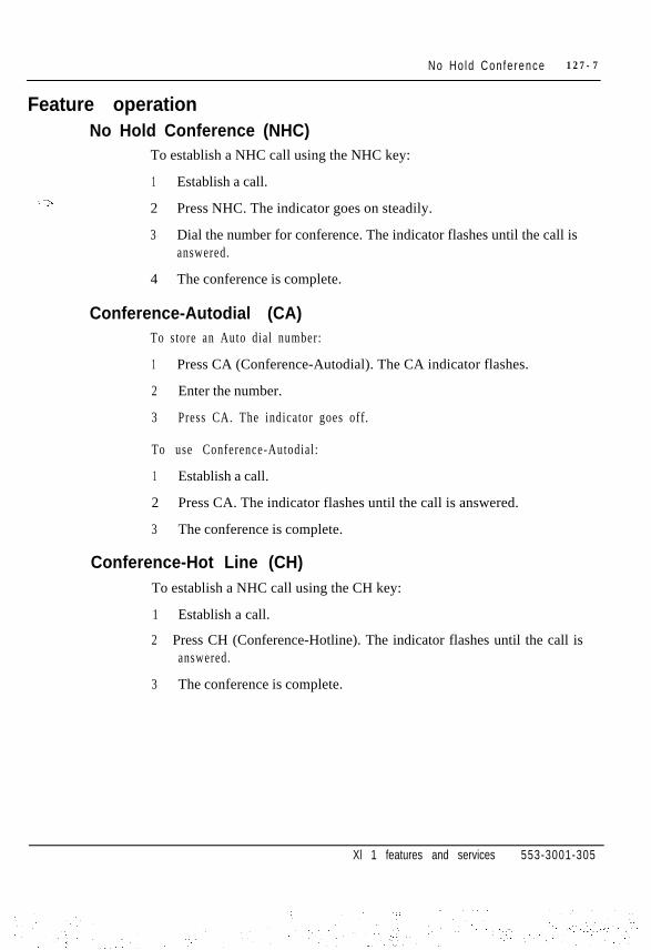
No Ho ld Con fe rence 127-7
Feature operationNo Hold Conference (NHC)
To establish a NHC call using the NHC key:
1 Establish a call.:>
2 Press NHC. The indicator goes on steadily.
3 Dial the number for conference. The indicator flashes until the call isanswered.
4 The conference is complete.
Conference-Autodial (CA)To store an Auto dial number:
1 Press CA (Conference-Autodial). The CA indicator flashes.
2 Enter the number.
3 Press CA. The indicator goes off.
To use Conference-Autodial:
1 Establish a call.
2 Press CA. The indicator flashes until the call is answered.
3 The conference is complete.
Conference-Hot Line (CH)To establish a NHC call using the CH key:
1 Establish a call.
2 Press CH (Conference-Hotline). The indicator flashes until the call isanswered.
3 The conference is complete.
Xl 1 features and services 553-3001-305

127-t


128-2 Nor th Amer ican Number ing P lan
It is important to avoid conflicts among NPAs, Central Office prefixes, andLOCs. It is recommended that customers implement l+ dialing to eliminateambiguity.
Customers who use the Autodial feature, Speed Call, or the HOT Line featuremay need to modify the l is ts and tables associated with these features toaccommodate the new prefixes or to reflect changes to numbers resultingfrom implementation of l+ dialing.
The remainder of this section discusses the procedure that Basic AlternateRoute Selection (BARS)/Network Alternate Route Selection (NARS)customers need to fol low to handle the NPA changes. Although AlternateRoute Selection (ARS) and Direct Trunk Access customers need not modifytheir databases, those who use Call Detail Recording and/or Toll DeniedClass of Service should consider the effect of NPA changes on theiroperat ions.
X1 1 features and services 553-3001-305
:


128-4 Nor th Amer ican Number ing P lan
Software modifications enable users to enter the new interchangeable NPAsin the following tables:
- Customer Data Block, LD15. Changed to allow interchangeable NPAentry.
- Electronic Switched Networking (ESN) Translation tables, LD90.Changed to al low interchangeable NPA format to be entered in responseto NPA and HNPA prompts. Responses are compared to NARWBARScall digits to determine call routing.
- Free Calling Area Screening (FCAS) tables, LD87. Changes allow usersto enter the interchangeable NPA format in response to the NPA prompt.Prompt values are compared to dial digits to determine if FCAS shouldscreen call .
- Feature Group D (FGD) Code Restriction tables, LD19. Changes allowentry of interchangeable NPA format in response to the NPA prompt.Feature Group D uses the response to restr ict certain calls that terminateat, or tandem through, a given node.
- M9llNumbering Plan Digit/Information Digit (NPID) tables, LD16.Change allows entry of interchangeable NPA format.
This software is available beginning with X11 release 19. Upgrades may alsorequire hardware modification depending on route selection capabilities,system type, and software release.
Direct Trunk Access and Alternate Route SelectionDirect Trunk Access and Alternate Route Selection customers need notupdate software to support interchangeable NPAs. Customers using DirectTrunk Access should continue to monitor local dial ing procedures to ensurecorrect toll call recognition.
System UpgradesUpgrade requirements can include hardware and software. For specificinformation, consul t Upgrade system. ins tal lat ion (553-3001-250).
Xl 1 features and services 553-3001-305
.: :i. ,

Nor th Amer ican Number ing P lan 128-5
Feature implementationThe following prompts have been modified to accept NPA input in the newinterchangeable format:
LD15 - Home Numbering Plan Area modification
Prompt R e s p o n s e Descr ip t i on
ISDN Y E S Change ISDN opt ions
-HNPA 200-999 Home Number ing P lan Area code1200- I 999
LD16-NPA code definition for the M911 feature
Prompt
TYPE
IDTB
NPID
TRMT
NPA
R e s p o n s e
NPID
o-7
o-9
NPA
200-999
Descr ip t i on
Numbering Plan Digit/Information Digit table
NPID tab le number
NPID to be translated
NPID treatment
Number ing P lan Area code
LD19 - NPA input for incoming Feature Group D AN1 screening
Prompt 1 Response 1 Description
TYPE
ANIT
NPA
ANI Feature Group D data block
(OVF), RAN xxx, Invalid ANI treatmentDN xxx, NCOS xxx
200-999 Three ANI digits in NPA format (prompt accepts only threedigits even if I+ dialing is in effect)
Xi 1 features and services 553-3001-305

128-6 Nor th Amer ican Number ing P lan
LD87 - Free Call Area Screening definition
Prompt
FCI
NPA -
R e s p o n s e Descr ip t i on
xxx Free Call Area Screening table index number
200-999 Area code or extended NPA code translation (only three200-999 200-999 digits accepted even if 1+ dialing is in effect)
LD90 - NARVBARS
Prompt
TRAN
NPA
HNPA
R e s p o n s e Descr ip t i on
ACl, AC2, SUM
200-999200-999 200-9991200-19991200-I 999 1200-I 999
Access code 1, 2, or summary tables
Area code or extended NPA code translation
200-9991200- l 999
Home Number ing P lan Area code
Xi 1 features and services 553-3001-305

Nor th Amer ican Number ing P lan 128-7
Carrier Access CodesA Carrier Access Code (CAC) gives a caller access to any interexchangecarrier or Operator Service Provider (OSP). FCC regulations require that CallAggregators, such as hotels, motels, hospitals , universi t ies, airports, gasstations, and pay telephone owners, provide selective access to the public.Callers dial the CAC to reach their desired carrier or OSP before dialing thetelephone number.
Aggregators, al though they must al low callers access to any long distancecaller, are permitted to block calls selectively. Selective equal access letsaggregators choose to block direct-dialed calls that result in charges to theoriginating telephone. Aggregators cannot block operator-assisted calls .
Northern Telecom provided an up-issue of Xl 1 release 14 in 1992 to conformto FCC Equal Access requirements. Beginning with X11 release 17, allsoftware releases support Equal Access. (X11 releases 1.5 and 16 do notsupport Equal Access.) Support for expanded codes, as described in thefollowing paragraph, is available beginning with X11 release 19.
The CAC has included a “10” identifying prefix followed by a three-digitCarrier Identification Code (CIC) for a total of five digits. New FCCregulations, reflected in Xl 1 release 19, require that the CAC expand to sevendigits: a “101” identifying prefix followed by a four-digit CIC. Theregulat ions require that both the old f ive-digi t format and the new seven-digitformat be supported for an 18 month permissive period during 1995 and1996. After this period, only the longer format will be supported.
X11 software allows the following operator-assisted North American andinternat ional dial ing sequences:
- CAC+O
- CAC + 0 + (NPA) + NXX + XXXX
- CAC+Ol+CC+NN
X11 software allows or denies these direct-dialed calls:
- CAC+l+(NPA)+NXX+XXXX
- CAC+Oll+CC+NN
Xl 1 features and services 553-3001-305

128-8 Nor th Amer ican Number ing P lan
where:
CAC = Carrier Access Code (10xXx or 1OlXXXX)
NPA = Numbering Plan Area (area code)
NXX = Central Office code format(N = any digit except 0 or 1; X = any digit (O-9))
XXXX = any four digits
CC = Country Code
NN = National number
Feature packagingEqual Access compliance is included in basic X11 software. The NetworkClass of Service package (NCOS, package 32) is required to configure EqualAccess.
Feature implementationCurrent Equal Access users who install new software prior to the end of the1995/1996 FCC interim period must set the Original Carrier Access Code(OCAC) flag in LD17 to YES when they upgrade their software or beginusing a release that supports the CAC expansion feature.
For complete information on implementation and configuration, refer to“Equal Access Compliance” on page 79-l.
Xl 1 features and services 553-3001-305

129-1
i ssued: 93 08 01Status: StandardXl 1 Release: Al l
Off Hook Alarm SecurityWith X1 1 release 18 and later, Off Hook Alarm Services (OHAS) allows anycall to be intercepted to a customer defined Directory Number (DN) otherthan an attendant, for example, a security DN. OHAS treatment is determinedon a set basis by assigning a class of service called Alarm Security Allowed(ASCA).
By enhancing l ine-lockout , telephones with Alarm Securi ty Allowed (ASCA)class of service are intercepted to customer defined Directory Numbers (DNs)when the dial tone/interdigit timer expires or the telephone is Forced Out ofService (FSVC). Telephones without ASCA continue to use the existingline-lockout treatment. (Refer to the Line Lockout module in this document).
An Off Hook Alarm Security (OHAS) DN can be a single appearanceDirectory Number (DN), Multiple Appearance DN, or an Automatic CallDistribution (ACD) DN. The OHAS DN cannot be an Attendant DN, ListedDN, a SPRE, Virtual ACD Agenr, or a Trunk Access Code. To receive OHAStreatment, a telephone must have Alarm Security Allowed (ASCA) class ofservice. To associate a telephone with an OHAS DN:
- Assign the ASCA class of service in LDlO or LD 11.
- Assign an Off Hook Interdigit OHAS number (OHID) in LD 10 or LD 11.
- For digital telephones only, assign a Forced Out of Service (FSVC)OHAS number in LDl 1.
- Associate the OHID and FSVC (if necessary), and the Alarm SecurityTimer (ASTM) to an OHAS DN through the ODNx prompt in LD15.
If the ASCA class of service is assigned, but the telephone is not associatedto an OHAS DN, an error message appears on the maintenance TTY when thesystem tries to redirect the call.
Xi 1 features and services 553-3001-305
:
:. . .
. . ~., ,: .-..,.,::.: ~

129-2 Off Hook Alarm Security
The Alarm Security Timer (ASTM) provides dial tone and interdigit timingfor telephones with ASCA class of service. The ASTM does not apply totelephones being Forced Out of Service (FSVC).
Telephones associated with OHAS DNs intercept to single-appearance DNs,Multiple Appearance DNs, or ACD DNs. OHAS treatment is provided if oneof the following events takes place on a telephone associated with an OHASDN:
- Dial tone timeout
- Interdigit timeout
- Digital telephones FSVC
Dial tone and interdigit timeout-call treatmentA telephone associated with an OHAS DN that receives a dial tone orinterdigit timeout intercepts to the OHAS DN specified by the telephone’sOff Hook Interdigit OHAS number (OHID).
FSVC-call treatmentA digital telephone is considered FSVC when the line is cut, damaged, orunplugged.
The FSVC OHAS treatment applies only to digital telephones. A telephoneassociated with an OHAS DN that is FSVC intercepts to the OHAS DNspecified by the telephone’s FSVC number.
Multiple OHAS DNsThe two methods for handling multiple OHAS DNs are zone and eventdependent, and are described in the following sections.
Xl 1 features and services 553-3001-305

Off Hook Alarm Security 129-3
Multiple OHAS DNs-zone dependentOHAS allows for multiple OHAS DNs within a single customer, enabling thecustomer to create multiple zones.
For example, a hospital with several locations can define separate OHASDNs for each location and define each distinct location as a zone. InFigure 129-1, the hospital has four zones. A separate OHAS DN is definedfor each of the four zones. Zone 0 uses OHAS DN 0, Zone 1 uses OHAS DN1, and so on. Each telephone in Zone 0 defines the OHID and FSVC numbersto 0; each telephone in Zone 1 defines the OHID and FSVC numbers to 1, andso on .
Figure 129-lZone Dependent example
pz-( )ziiY
if Hospita)q553-5523
Xl 1 features and services 553-3001-305

129-4 Off Hook Alarm Security
Multiple OHAS DNs-event dependentOHAS can distinguish between OHID timeout and the FSVC events byhaving a single telephone with separate OHAS DNs for OHID timeout andFSVC events. For example, a telephone can be defined with a FSVC number1 and OHID number 2. If a dial tone/interdigit timeout occurs, the telephoneintercepts to OHAS DN 2. If the same telephone is FSVC, OHAS DN 1 isnot i f ied .
Figure 129-2Event Dependent example
I IZ o n e 0
OHAS DN 0 I
OHAS D N 2
@Ja8Q
Xl 1 features and services 553-3001-305
. . . :

Off Hook Alarm Security 129-5
OHAS TTY displayEvery time an OHAS intercept treatment takes place, a message is sent to allmaintenance TTYs. This message contains an OHAS message indicator, theoriginating DN and TN, and a time stamp.
Format
OHASxxxx
Output example
lscu time stamp
O H A S O O O O 5003 1 0 1 0 04:30:21
Note: The two possible OHAS messages are:OHASOOOOOHAS treatment due to dial tonelinterdigit timeoutOHASOOOl OHAS treatment due to Forced Out of Service call treatment
Operating parametersOHAS is not supported for at tendants or networks.
OHAS intercept treatment for telephones FSVC is provided only for thefol lowing telephones:
- M2009, M2112, and M2018
- M 2 3 1 7
- M 3 0 0 0
- M2006, M2216, M2616, M2008, and M2016
The Alarm Security Timer (ASTM) does not apply to telephones beingFSVC.
The t iming for recognizing a FSVC condit ion depends on the type of card thatthe sys tem is us ing:
- The Integrated Services Data Line Cards (ISDLCs) take approximately6 sec. to recognize a FSVC condition.
- Peripheral Controller cards take approximately 1 sec. to recognize aFSCV condition.
Once a trunk is seized, OHAS treatment does not apply.
Xl 1 features and services ~753-3001-305

129-6 Off Hook Alarm Security
Feature interactions- Call Redirection
Call Redirection features defined for telephones with ASCA class ofservice work as currently defined in the system. The Call Redirectionfeatures include the following:
. Call Forward All Calls
. Call Forward No Answer
. Call Forward Busy
. Call Forward by Call Type
. Call Pickup
. Hunt ing
- Call TransferA telephone receives the OHAS treatment if the telephone has ASCAclass of service and attempts to transfer a call and the ASTM expires.
- ConferenceThe OHAS line-lockout treatment occurs when a telephone associatedwith an OHAS DN initiates a conference call and the ASTM expires.Only the conference initiator receives the OHAS treatment; otherconferees remain in conference. If the initiator of the conference callpresses the conference key, the OHAS DN is conferenced in with theother conferees.
- Line-lockoutOHAS treatment occurs when a telephone with ASCA class of servicereceives an interdigit or dial tone timeout. The ASTM is used instead ofthe dial tone and interdigit timers (DIDT and DIND, respectively)normally used for LLT and DLT line-lockout treatment.
- No Hold Conference (NHC)OHAS treatment occurs when a telephone with ASCA class of serviceattempts a NHC call and the ASTM expires. The OHAS DN isconferenced in with the other conferees.
- Last Number Redial/Stored Number RedialOHAS treatment may apply to these features if the ASTM expires.
Xl 1 features and services 553-3001-305

Off Hook Alarm Security 129-7
- ESN and trunk access codesIf an ESN or trunk access code is dialed, the dial tone/interdigit timer isstopped and the set wil l not recall to the designated ODN after thespecified t ime period has elapsed.
- Room StatusOHAS and Offhook Detection in Room Status feature are mutuallyexclusive.
- System Speed Call/Speed CallOHAS treatment may apply to these features if the ASTM expires. TheAlarm Security Timer may expire for the following reasons:
. A dial tone or interdigit timeout occurs while dialing the speed callaccess code.
. The Speed Call being accessed has an asterisk (*) c a u s i n g a3-second delay. If the ASTM is 3 seconds or less, the OHASintercept treatment may occur.
Feature packagingOHAS is included in X11 base system software.
Feature operationThere is no procedure required to operate this feature.
Xi 1 features and services 553-3001-305

129-8 Off Hook Alarm Security
Feature implementation
LD15 - Define the Off Hook Alarm Services (OHAS) Directory Numbers (DNs).
REQ N E W , C H G Add or change a customer
T Y P E C D B Cus tomer Da ta B lock
CUST o-99 Cus tomer number
LLT (OVF), ATN, OFA Flexible line-lockout treatment
OHAS YES, (NO) Change OHAS paramete rs .
The following prompts occur only if OHAS YES.
-0DNO xxx...x OHAS DN 0
-0DNi xxx...x OHAS D N 1
-0DN2 xxx...x OHAS DN 2
-0DN3 xxx...x OHAS DN 3
-0DN4 xxx...x OHAS DN 4
-0DN5 xxx...x OHAS DN 5
-0DN6 xxx...x OHAS DN 6
-0DN7 xXx.,.x OHAS DN 7
-0DN8 xxx...x OHAS DN 8
-0DN9 xxx...x OHAS DN 9
-ASTM l-(30)-63 The timer applies to all OHAS DNs and is programmable inone-second inc rements .
Note: OHAS DNs must have ASCA class of service assigned in LDlO or LDll.
Xl 1 features and services 553-3001-305

Off Hook Alarm Security 129-9
LDlO - Assign Alarm Security Allowed (ASCA) class of service
R E Q N E W , C H G Add or change a PBX telephone
N P E 500,250O
C&S ASCA, (ASCII)
Te lephone type
ASCA, A la rm Secur i t y Den ied (ASCD)
OHID OHID
Note: When ASCA is assigned, the OHAS DN must be defined in LD1.5.
LDll -Assign Alarm Security Allowed (ASCA) class of service
R E Q N E W , C H G Add or change a BCS telephone
TYPE aaaa Telephone typeaaaa = SLl ,2006,2008,2009,2016,2018,2112,2216,2317,2616,3000
CLS ASCA, (ASCD) ASCA, ASCD
OHID w-9 OHID
FSVC ( O ) - 9 FSVC OHAS DN number
(FSVC prompt is given only to digital telephones)
Note: When ASCA is assigned, the OHAS DN must be defined in LD15.
Feature operationThere is no specific procedure required to operate this feature.
Xl 1 features and services 553-3001-305
:.
,.. . . ~; : : ,, . xi:, ..:: ,, :

129-10 Off Hook Alarm Security
Xl 1 features and services 553-3001-305

Off-Premise ExtensionThe Off-Premise Extension (OPX) feature allows a single line telephoneserving as an extension to be located away from the customer premises. Theloop l imit is 1400 ohms to the s tat ion or equivalent long-l ine circui t interface.Distance varies depending on the gauge of wire used.
Refer to Northern Telecom Publication 500/25OO line curds description andoperation (553-2201-183) for additional information.
Operating parametersThe Off-Premise Extension (OPX) feature applies only to single linetelephones. A QPC192 line circuit pack must be equipped.
Feature interactionsRefer to 500/2.500 l ine cards descript ion and operat ion (553-2201-183).
Feature packagingOff-Premise Extension (OPX) is included in basic Xl 1 system software.
Feature implementation
LDlGAdd or change Off-Premise Extension class of service for single line telephones.
R E Q C H G Change
TYPE 5 0 0 Telephone type
T N l s c u Termina l Number
CLS OPX, (ONP) Telephone is an off-premises or on-premises extension
Xl 1 features and services 553-3001-305
..:

130-2 Of f -Premise Ex tens ion
Feature operationThere is no specific procedure required to operate this feature.
Xl 1 features and services 553-3001-305
: . : . . --

Issued: 92 1231Status: StandardXl 1 Release: Al l
131-1
Office Data Administration SystemThe Office Data Administration System (ODAS) package provides a methodfor retrieving administrative information stored in Meridian 1 memory. Thisfeature can expedite administration and billing activities by significantlyreducing the need for manual records.
The Station Line Designator (DES) code is any alphanumeric code of one tosix characters. The customer selects this number which can help the customergroup telephones according to users, f loor location, or any other category.
The fol lowing table l is ts the types of data that can be printed using OfficeData Administrat ion System (ODAS) and the overlay program to use for eachtask:
Type of print required LD
Count telephones with specified feature(s) 8 1
List Directory Number (DN) blocks by DATE entry 2 2
List DN blocks by station line designator (DES) entry 2 2
List Terminal Number (TN) alphabetically by DES 8 3
List TN with specified DATE entry 2 0
List TN with specified DES entry 2 0
Pr in t Mul t ip le Appearance Groups 8 2
Print TN to DES correlation for specified feature(s) 8 1
Print TN data blocks with specified DATE entry 2 0
Print TN data blocks with specified DES entry 2 0
Xi 1 features and services 553-3001-305

131-2 Office Data Administration System
Refer to the Northern Telecom Publication Ojj%x Data AdministrationSystem description and engineering (553-2721-100) for a completedescription of Office Data Administration System (ODAS).
Operating parametersI t is recommended that 1200 baud printers be used on larger systems to reducethe t ime required to obtain ODAS printouts . When a system is equipped witha 1200 baud printer, a 300 baud device must not be assigned to perform thesame funct ion.
Feature interactionsRefer to OfSice Data Adminis trat ion System descript ion and engineering(553-2721-100).
Feature packagingODAS, package 20, has no feature package dependencies.
Xl 1 features and services 553-3001-305
. . .. ;.: ..:
,

Feature implementation
Office Data Administration System 131-3
LD84/85 -Assign or change station line designator (DES) entry for telephones.
T N lscu Termina l Number
ES a...x DES (one to six alphanumeric characters)
LDlO-Assign or change DES entry for 500/2500 telephones.
R E Q C H G Change
TYPE 500 Telephone type
T N lscu Termina l Number
D E S a...x DES (one to six alphanumeric characters)
LDll-Assign or change DES entry for 500/2500, SL-1, M3000, and Meridian digital telephones.
R E Q C H G
TYPE aaaa
T N
D E S
l s c u
a...x
Change
Te lephone type
aaaa = SLI , 2006, 2008, 2009, 2016, 2018, 2112, 2216,2317, 2616,300O
Termina l Number
DES (one to six alphanumeric characters)
Feature operationThere is no specific procedure required to operate this feature.
Xi 1 features and services 553-3001-305

131-4 Office Data Administration System
Xl 1 features and services 553-3001-305

132-1
On Hook DialingThe On Hook Dialing feature enables an SL- 1 or Meridian digital telephoneuser to make a cal l without l i f t ing the handset . Signaling tones and the voiceof the called party are heard over the loudspeaker. For two-waycommunication, the user must l i f t the handset or act ivate the Handsfree uniti f equipped.
Operating parametersThe On Hook Dialing feature does not apply to 500/2500 telephones.
Feature interactionsThere are no feature interactions.
Feature packagingOn Hook dialing is included in basic Xl 1 system software.
Feature implementationNot applicable.
Feature operationThere is no specific procedure required to operate this feature.
Xl 1 features and services 553-3001-305

132-2 On Hook D ia l ing
Xi 1 features and services 553-3001-305

Issued: 92 1231Status: StandardXi 1 Release: 5
133-1
Optional Outpulsing DelayThe Optional Outpulsing Delay (OOD) feature increases to three seconds theStart of Dial ing Delay used for automated dial ing on loop start Central Officetrunks. This feature is required for Meridian 1 connection in some countries.
Operating parametersThere are no feature requirements.
Feature interactionsFeatures that automatical ly dial digi ts onto a loop star t CO trunk are providedwith an additional delay. These features include the following:
- Stored Number Redial
- Autodial
- Speed Call
- Call Forward All Calls
- Basic Alternate Route Selection/Network Alternate Route Selection(BARS/NARS)
- System Speed Call
- Network Speed Call
- Flexible Hotline
Feature packagingOptional Outpulsing Delay (OOD), package 79, has no feature packagedependencies.
Xl 1 features and services 553-3001-305

133-2 Opt iona l Outpu ls ing Delay
Feature implementationNot applicable.
Feature operationThere is no specific procedure required to operate this feature.
Xi 1 features and services 553-3001-305

Overlay Cache MemoryWith X 11 release 18 and later, Overlay Cache Memory uses Protected DataStorage (PDS) as a cache area for storing overlays loaded from disk. Thecache memory overlays are accessed much faster than those on disk, reducingthe load time to approximately one second.
A maximum of 32 overlays may reside in Overlay Cache Memory at onetime. The CACH prompt in LD17 defines the number of cache memorybuffers allocated in protected memory. Each overlay resides in a buffer. Azero entry deactivates this feature and requires all overlays to be loaded fromdisk .
Each buffer requires 19K of Protected Data Storage (PDS). If there isinsufficient memory to store the number of buffers requested, a warningmessage follows the LD17 prompt sequence. The message indicates thatmore memory is required to store all the caches requested.
If a small number of cache memory buffers are allocated, frequently usedoverlays may be removed from protected memory by seldom used overlays.The PRTY prompt in LD17 sets an overlay priority flag. A priority flagprevents the removal of an overlay from cache memory by loading anotheroverlay. The number of priority flags set cannot exceed the number of cachememory buffers specified.
When an LDxx command is entered, the cache memory is checked for therequested overlay. If the requested overlay is in cache memory, i ts dataportion is rapidly copied to the regular overlay area.
A requested overlay that is not in cache memory is loaded from the disk intothe normal overlay area and simultaneously stored into a cache memorybuffer, if one is available. If one is not available, the new overlay overwritesanother in the cache memory.
Xi 1 features and services 553-3001-305
:
I

134-2 Overlay Cache Memory
If an overlay is loaded from disk and no unused buffer area exists, the overlayused longest ago without i ts priori ty f lag set is removed and replaced by thenew overlay.
Operating parametersIf the feature is deactivated with a zero entry at the CACH prompt in LD17,no cache memory exists and all overlays are loaded from disk.
Cache memory is not affected by a system initialization. After a systeminitialization, it is not necessary to reload overlays from the disk.
Each buffer requires 19K of PDS. The number of cache memory buffersallocated by the system is limited by the availability of spare memory. Ifenough memory exists, a maximum of 32 cache memory buffers is allowed.Each buffer stores one overlay.
The number of overlay priorities set cannot exceed the number of cachebuffers allocated.
To load an overlay from disk use the command LDxx D. This is necessary forthe system to determine which overlay to read. The LDxx D command loadsthe overlay from disk and overwrites the same overlay existing in cachememory.
Using the LDxx D command to force load an overlay from disk does notsimultaneously support the peripheral download SUSP command.
When overlays are stored in cache memory, the ENLT and DIST commandsare not supported.
The system automatically stores and retrieves overlays from cache memory.If the cache area is full when a new overlay is requested, the overlay goneunused the longest without a priori ty f lag set is removed and replaced by thenew overlay. Daily routines and background loaded overlays are not stored incache memory.
The Overlay Cache Memory feature does not apply to Option 81 telephones.
Xl 1 features and services 553-3001-305
: :..

R E Q C H G
TYPE C F N
OVLY YES
C A C H (0), 2-32
P R T Y xx xx xx xx...
Over lay Cache Memory 134-3
Conversion and upgradesDue to memory requirements, installing a new issue of software or the sameissue with additional features may reduce the number of cache buffers thatcan be allocated. A warning message indicates this reduction has occurred.
If this reduction causes the number of overlay priorities to exceed themaximum number of cache buffers, the overlay priorities are reduced to equalthe number of cache buffers. The priorities are automatically reduced bybeginning with the highest overlay number and working downward.
Featur’e packagingThis feature is included in the base Xl 1 system software.
Feature implementation
LD17 - Change system configuration record
Change da ta
Configuration data block
Change over lay area
Number of overlay buffers held in cache memory.
Entering 0 disables the feature.
Set priority for the stored overlays. Priority can be set onlyfor the number of overlays specified in CACH. xx = theoverlay number.
An X preceding the number deletes the priority flag for thatoverlay.
Feature operationThere is no procedure required to operate this feature.

134-4 Over lay Cache Memory
Xl 1 features and services 553-3001-305

OverrideOverride allows a user to enter into an established connection. A warning tonenotif ies the talking part ies that a third party is about to enter the conversat ion.The warning tone is an initial one-second burst, followed by a 256-ms burstrepeated every 16 seconds.
The Override feature can be used after a user has dialed a busy DirectoryNumber (DN).
Operating parametersOn SL- 1 and digital telephones, a separate Override key must be assigned. Anassociated lamp is not required.
On 500/2500 telephones, Flexible Feature Code (FFC) is required to overridea call.
Override cannot be used to enter an established connection if any party(telephone or trunk) has Warning Tone Denied class of service. In this case,overflow tone is heard.
The system must have a conference loop.
Feature interactions- Conference
Override cannot be used to enter a conference call .
Feature packagingOverride is included in basic X1 1 system software.
For 500/2500 telephones, Flexible Feature Code (FFC), package 139, must beequipped.
Xl 1 features and services 553-3001-305

135-2 Overr ide
Feature implementation
LDlO- Allow Override for 500/2500 telephones.
R E Q
TYPE -..
T N
CLS
C H G
5 0 0
lscu
OVDA, (OVDD)
XFA, (XFD)
(WTA), WTD
Change
Te lephone type
Termina l Number
Override allowed or denied for this telephone
Transfer allowed or denied
Warning Tone Allowed or Denied (WTA is required to be~ overridden)
LDll -Add or change Override for SL-1 and digital telephones.
REQ
TYPE
T N
CLS
KEY
C H G
aaaa
l s c u
(WTA), WTD
xx OVR
Change
Te lephone type
aaaa = SLI ,2006,2008,2009,2016,2018,2112,2216,2317,2616,3000
Termina l Number
Warning Tone Allowed or Denied (WTA is required to beoverr idden)
Override key (must be key 34 for M3000)
LD14 - Define Warning Tone Allowed for trunks to permit Override.
R E Q
TYPE
T N
CLS
C H G
aaa
l s c u
W-W, WTD
Change
Trunk typeaaa = ADM, AID, ATVN, AWR, CAA, CAM, COT, CSA, DC,DID, FEX, ISA, MDM, MUS, PAG, RAN, RCD, RLM, RLR,TIE, WAT
Termina l Number
Warning Tone Allowed or Denied (WTA is required to beoverr idden)
Xi 1 features and services 553-3001-305

Override 135-3
LD57 - Configure Flexible Feature Code (FFC) for Override on 500/2500 telephones.
R E Q C H G
TYPE F F C
CpT o-99
C O D E OVRD
OVRD xxxx
Change
Flexible Feature Codes
Cus tomer number
Change Over r ide access code
Over r ide access code
Feature operationTo override a call in progress from a SL-1 or digital telephone:
1 Dial the number. You hear a busy tone.
2 Press Override. Everyone hears a one-second tone burst .
3 You are connected to the call. ‘-
To cancel Override from a SL-1 or digital telephone:
1 Press Release or hang up.
2 You are disconnected. The original call remains active.
To override a call in progress from a 500/2500 telephone:
1 Dial the number. You hear busy tone.
2 Flash the switchhook or press LINK.
3 Dial the Flexible Feature Code (FFC) for Override. Everyone hears aone-second tone burst .
4 You are connected to the call.
To cancel Override from a 500/2500 telephone:
1 Press Release or hang up.
2 You are disconnected. The original call remains active.
Xl 1 features and services 553-3001-305
. -.

135-4 Overr ide
-_
Xl 1 features and services 553-3001-305

Issued: 92 12 31S ta tus : StandardXi 1 Release: -1Al l
136-1
PagingThe Meridian 1 provides switching access and trunk circuit interface to acustomer-supplied speaker or radio paging equipment. Paging equipment isaccessed by dial access or a Page key on attendant consoles. Telephonescannot be assigned a Page key and must dial access this feature.
Attendant consoles using the Page key preempt telephones having only dialaccess. Telephones preempted by the attendant are disconnected and mustre-access the paging trunk.
Time Forced Disconnect (TFD), Xl 1 release 15 and later software providesa variable timer to force disconnect Paging trunks. The timer is defined on aroute basis to limit the time a user can keep a Paging trunk seized. When thetimer expires, the call is disconnected from the trunk.
The trunk is disconnected when the Time Forced Disconnect (TFD) timerexpires in all cases, regardless of the status of the trunk at the time. Timingstarts as soon as the trunk is seized (not when the cal l is established), so thetimer must allow some delay for connection time.
The Time Forced Disconnect timer is used on the following trunk types:
- C O T Central Office- D I C Dictat ion- F E X Foreign Exchange- P A G Paging t runks- T I E Tie direct lines- W A T Wide Area Telephone Service
Xl 1 features and services 553-3001-305
.

136-2 Paging
Operating parametersStat ion dial access to the Paging trunk is restr icted by the Trunk GroupAccess Restriction (TGAR) code entered in LDlO or LDll.
Unique access codes are required for each Paging route.
Unique feature keys are assigned for each Paging route.
All Zone Paging is not available with Meridian 1 unless the customerprovided paging equipment is equipped with separate “al l-zone” input .
The following requirements apply to the Xl 1 release 15 Time ForcedDisconnect (TFD) feature:
- The t imer can only be assigned on a route basis and not to individualtrunks. All trunks in a route have the same timer value.
- After a timer value is changed, it does not take effect on a given trunkunti l that t runk is released and seized again.
- Changing a timer value to zero effectively removes the TFD timer fromall the t runks in that route.
- The range of the timer is 1 hour, in 30-second increments (O-3600). TheTFD timer is independent of all other timers.
Feature interactions- Private Line Routes
Route 31 cannot be assigned as a paging route on X11 release 13 andearlier software.
Trunks forced off by TFD are disconnected normally, accompanied by anerror message (ERR4054) output on the system terminal. The error messageidentifies the Originating Terminal Number (TN), Terminating TerminalNumber (TN), date, and time for the following trunk types:
- analog trunks
- Digital Trunk Interface (DTI) trunks
- ISDN ISL/PRI trunks
Xi 1 features and services 553-3001-305
. :’
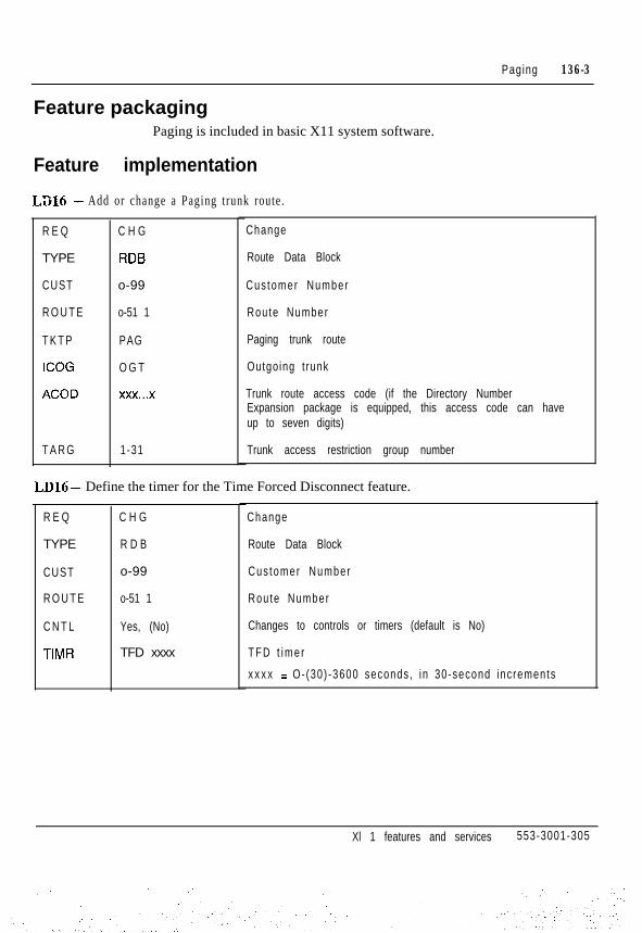
Paging 136-3
Feature packagingPaging is included in basic X11 system software.
Feature implementation
LX6 - Add or change a Paging trunk route.
R E Q
TYPE
CUST
R O U T E
T K T P
ICOG
ACOD
T A R G
C H G
RDB
o-99
o-51 1
PAG
O G T
xxx...x
1-31
Change
Route Data Block
Cus tomer Number
Route Number
Paging trunk route
Outgoing t runk
Trunk route access code (if the Directory NumberExpansion package is equipped, this access code can haveup to seven digits)
Trunk access restriction group number
LD16- Define the timer for the Time Forced Disconnect feature.
R E Q
TYPE
CUST
R O U T E
C N T L
TIMR
C H G
R D B
o-99
o-51 1
Yes, (No)
TFD xxxx
Change
Route Data Block
Cus tomer Number
Route Number
Changes to controls or timers (default is No)
T F D t i m e r
x x x x = O- (30) -3600 seconds , in 30-second inc rements
Xl 1 features and services 553-3001-305

136-4 Paging
R E Q C H G Change
TYPE PAG Paging t runk
T N lscu Termina l Number1 --.
XTRK XUT, XEM Universal Trunk Card (NT8D14), E&M Trunk Card(NT8D15). Prompted only for superloops and the first uniton the card.
CUST o-99 Cus tomer Number
SIGL D X 2 DX signalling (2-wire) - QPC71 onlyD X 4 DX signalling (Cwire) - QPC71 and NT8Di5EAM E&M signalling (2-wire) - QPC71 and NT8D1.5E M 4 E&M signalling (4-wire) - QPC71 and NT8D15L D R Loop dial repeating - QPC71 and NT8Dl4/15O A D Outgoing automatic, incoming dial - QPC71, NT8DI4/15
S T R O IMM Immediate start outgoingW N K Wink start outgoingD D L Delay dial outgoing
SUPN Yes, (No) Answer and d isconnect superv is ion requ i red
LD12 - Assign Paging key for an at tendant console. No programming is required to al low theat tendant dial access to Paging.
LD14- Add or change a Paging trunk within the Paging trunk route.
R E Q
TYPE
T N
KEY
C H G
ATT, 1250,225O
l s c u
xx PAG yyy...y
Change
Conso le t ype
Termina l Number
Paging key
xx = key number (O-9 on Ml 250, O-l 9 on M2250) yy...y =access code of Paging trunk route
Xl 1 features and services 553-3001-305

Paging 136-5
LDlO - Allow or deny dial access to Paging for 500/2500 telephones.
R E Q
TYPE
T N
TGAR
C H G
5 0 0
lscu
xx
Change
Te lephone type
Termina l Number
Allow/deny access to Paging trunk
LDll -Allow or deny dial access to Paging for SL-1 and Meridian digital telephones.
R E Q
TYPE
T N
TGAR
C H G
aaaa
l s c u
xx
Change
Te lephone type
aaaa = SLl ,2006,2008,2009,2016,2018,2112,2216,2317, 2616,300O
Termina l Number
Allow/deny access to Paging trunk
Feature operationThere is no specific procedure required to operate this feature.
Xi 1 features and services 553-3001-305

136-6 Paging
Xi 1 features and services 553-3001-305

137- l
PretranslationIn a business or hospi ta l i ty environment , many communicat ions s i tuat ionscan be simplified with a flexible dialing plan. Pretranslation lets you create asuch a plan by using Speed Cal l l is ts as Pretranslat ion Tables .
Some typical uses of Pretranslation are:
- room number to DN correlation
- Parti t ioning of telephones by category, group, department, f loor,building, room, special service, and so on
- internal call restrictions
- expanded customer dialing capability
The dialing capabilities and/or restrictions of each Pretranslation group aredefined in Pretranslation Tables. The tables are Speed Call lists modified forPretranslat ion.
With Pretranslation, only the first dialed digit of a call is pretranslated. Thetranslation choices are:
- Pass the digit as dialed with no changes
- Replace the first dialed digit with a specified substitute digit or digits,and pass the remaining digi ts unchanged
- Delete the f i rs t dialed digi t and pass the remaining digi ts unchanged
- Block the call based on the first digit dialed
Xl 1 features and services 553-3001-305

137-2 Pret rans la t ion
The pretranslator must deal with al l telephones, t runks and consoles capableof delivering a dialed digit to the Meridian 1 digit processor. Each of thesemust be assigned to one of 25.5 Pretranslat ion groups. The groups aregeneral ly set up as fol lows:
-.,-- trunk and DISA calls default to group 0
- attendant consoles are always unrestricted and are unaffected bypretranslat ion
- telephones and terminals default to group 0, but may be assigned togroups l-254.
Note: Before Xl 1 release 14, there are a maximum of 8 Pretranslationgroups (O-7).
The dialing capabili t ies of each group are reflected by the codes storedagainst entries in the Pretranslation table. The four possible codes are:
*
C o d e
Block call
Function
%-A-k Delete Pretranslation (first dialed) digit,pass remain ing d ig i ts unchanged
space <CR>
xxxx...x
Pass Pre t rans la t ion d ig i t unchanged
Pretranslate digit into xxxx...x
(xxxx...~ = replacement DN)
Only the f i rs t dialed digi t is sent from the digi t processor to the pretranslator .The pretranslator looks up the stored code for the dialed digit in thePretranslat ion table associated with the cal l ing terminal , applies the treatmentspecified by the entry and passes the result to the DN translator. From thenon, the cal l is processed normally. Pretranslat ion of the cal l is f inished at thispoint, unless call modification procedures, such as a Call Transfer, areinvolved.
Xi 1 features and services 553-3001-305

Pret rans la t ion 137-3
Setting up dialing plans and Pretranslation tablesSteps needed to set up pretranslat ion:
1 Identify the customer numbering plan.
2 Determine access and restrict ions for each pretranslation call ing group.
3 Determine dialing requirements and instructions for the pretranslationcalling groups and create a Pretranslation Table for each group.
4 Implement the feature.
A hotel has been chosen as a model to i l lustrate the principles ofPretranslat ion and how to set up Pretranslat ion. However, Pretranslat ion canbe applied to many other business environments .
Table 137-1Description of model
Hotel with 12 floors containing administrative offices, hotel services andguest rooms.
Floor 1 - Lobby, gift shop, restaurants and administrative offices
Floor 2 - Meeting rooms, salon and additional office space
Floor 3 - Banquet rooms and health club
Floors 4-l 2 - Guest rooms (floors 4-9 each have 50 rooms, floors 1 O-l 2each have 25 suites)
Xi 1 features and services 553-3001-305

137-4 Pret rans la t ion
Step I-Identify the numbering planThe model hotel’s numbering plan is shown in Table 137-2.
Table 137-2Numbering plan for model
Available numbers Assigned to: Actual DNs used
0 Operator 0
1 Guest rooms on floor 1 0 1001- l 026Guest rooms on floor 1 1 1101-1126Guest rooms on floor 1 2 1201- l 226
2 R o o m s e r v i c e 2001C a f e 2002Restaurant 2003Gift shop 2 0 0 4Health club 2005Salon 2006Housekeep ing 2007Bel l Capta in 2008Valet 2009Meet ing rooms 2100-2199Administrative offices 2300-2599Secur i t y 2700Front desk 2730Lobby te lephones 2750-2765Misce l laneous 2800-2899
3 SPRE code
4 unused
5 unused
6 Trunk access codes 620-635
7 Guest rooms on floor 4 7401-7451Guest rooms on floor 5 7501-7551Guest rooms on floor 6 7601-7651Guest rooms on floor 7 7701-7751Guest rooms on floor 8 7801-7851Guest rooms on floor 9 7901-7951
8 unused
9 BARS access codes 9
Xi 1 features and services 553-3001-305
. -. I~... ._. ‘. .;
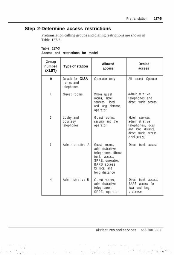
Pret rans la t ion 137-5
Step 2-Determine access restrictionsPretranslation calling groups and dialing restrictions are shown inTable 137-3.
Table 137-3Access and restrictions for model
Groupnumber Type of station
Allowed Denied
(XL-)access access
0 Default for DISA Operator on ly All except Operatort runks andte lephones
1 Gues t rooms Other gues t Admin i s t ra t i verooms, hotel te lephones andservices, local direct trunk accessand long distance,operator
2 Lobby and Gues t rooms , Hotel services,cou r tesy security and the admin i s t ra t i vete lephones operator te lephones , loca l
and long distance,direct trunk access,and SPRE
3 A d m i n i s t r a t i v e A Guest rooms, Direct trunk accessadmin i s t ra t i vete lephones , d i rec ttrunk access,SPRE, opera to r ,BARS accessfor local andlong d i s tance
4 A d m i n i s t r a t i v e B Gues t rooms , Direct trunk access,adm in i s t ra t i ve BARS access forte lephones , local and longSPRE, opera tor d i s t a n c e
Xi I features and services 553-3001-305

137-6 Pre t rans la t ion
Step 3-Determine dialing requirements and createPretranslation Tables
Dialing instructions for Group Zero in this model are shown in Table 137-4and the corresponding Pretranslation Table is listed in Table 137-5.
: For an explanation of the groups used in this model, see Table 137-3.
Table 137-4Group 0 - Default for unassigned trunks and telephones
Actual digits dialed I Desired destination
6
7
8
9
0
Operator
Operator
Operator
Operator
Operator
Operator
Operator
Operator
Operator
Operator
Xl 1 features and services 553-3001-305
:. .‘._. . :.-

Pret rans la t ion 137-7
Table 137-5Group 0 - Pretranslation Table (default)
Digit Code Function Destination
1 0 rep lace Operator
2 0 rep lace Operator
3 0 rep lace Operator
4 0 rep lace Operator
5 0 rep lace Operator
6 0 rep lace Operator
7 0 rep lace Operator
8 0 rep lace Operator
9 0 rep lace Operator
0 space <CR> pass Operator
Xi 1 features and services 553-3001-305
I

137-8 Pret rans la t ion
Dialing instructions for Group One in this model are shown in Table 137-6and the corresponding Pretranslation Table is listed in Table 137-7.
Table 137-8Group 1 - Guest dialing instructions for model
Actual digitsdialed
Desired destination
I X X X Guest rooms on floors 1 O-1 2
2 Secur i t y
3 SPRE (housekeeping staff for Room Status)
4 Front desk
5 1 Room Se rv i ce
5 2 C a f e
5 3 Restaurant
5 4 Gift shop
5 5 Health club
5 6 Salon
5 7 Housekeep ing
5 8 Bell captain
5 9 Valet
7xxx Guest rooms on floors 4-9
8 Long distance calls
9 Local calls
0 Operator
Xi 1 features and services 553-3001-305
.::..- ~- .

Pret rans la t ion 137-9
Table 137-7Group 1 - Pretranslation Table (Guests)
Digit Code Function Destination
1 space <CR> pass Gues t rooms
2 2700 rep lace Secur i t y
3 space <CR> pass S P R E
4 2730 rep lace Front desk
5 (see Note) 200 rep lace Gues t se rv ices
6 * block call not used
7 space <CR> pass Gues t rooms
8 620 rep lace Long distance calls
9 space <CR> pass Local calls
0 space <CR> pass Operator
Note: When a guest dials 51 for room service, the digit “5” is translated to the entry“200” and the 1 is passed as is, resulting in the extension “2001.”
Dialing instructions for Group Two in this model are shown in Table 137-8and the corresponding Pretranslation Table is listed in Table 137-9.
For an explanation of the groups used in this model, see Table 137-3.
Table 137-BGroup 2 - Lobby and courtesy telephone dialing instructions
Actual digitsdialed Desired destination
1 xxx Gues t rooms o n f loo rs 1 O-1 2
2 Secur i t y
7xxx Guest rooms on floors 4-9
0 Operator
Xl 1 features and services 553-3001-305

137-l 0 Pretranslation
Table 137-9Group 2 - Pretranslation Table (Lobby and courtesy telephones)
Digit Code Function Destination
1 space <CR> pass Gues t rooms
2 2700 rep lace Secur i t y
3 * block call not used
4 * block call not used
5 * block call not used
6 * block call not used
7 space 4%~ pass Gues t rooms
8 * block call not used
9 * block call not used
0 space <CR> pass Operator
Dialing instruct ions for Group Three in this model are shown in Table 137-10and the corresponding Pretranslation Table is listed in Table 137-11.
Xl 1 features and services 553-3001-305

Pretranslation 137-11
For an explanation of the groups used in this model, see Table 137-3.
Table 137-10Group 3 - Administrative A dialing instructions for model
Actual digitsdialed
1 xxx
2xxx
3
7 x x x
9
0
Desired destination
Guest rooms on floors 1 O-1 2
Admin is t ra t ive te lephones
S P R E
Guest rooms on floors 4-9
Loca l / long d is tance th rough BARS
Operator
Table 137-l 1Group 3 - Pretranslation Table (Administrative A)
Digit Code Function
1 space <CR> pass
2 space <CR> pass
3 space <CR> pass
4 * block call
5 * block call
6 * block call
7 space <CR> pass
8 * block call
9 space <CR> pass
0 space <CR> pass
Destination
Gues t rooms
Admin i s t ra t i vete lephones
S P R E
not used
not used
not used
Gues t rooms
not used
Loca l / l ong d i s tanceth rough BARS
Operator
Xl 1 features and services 553-3001-305
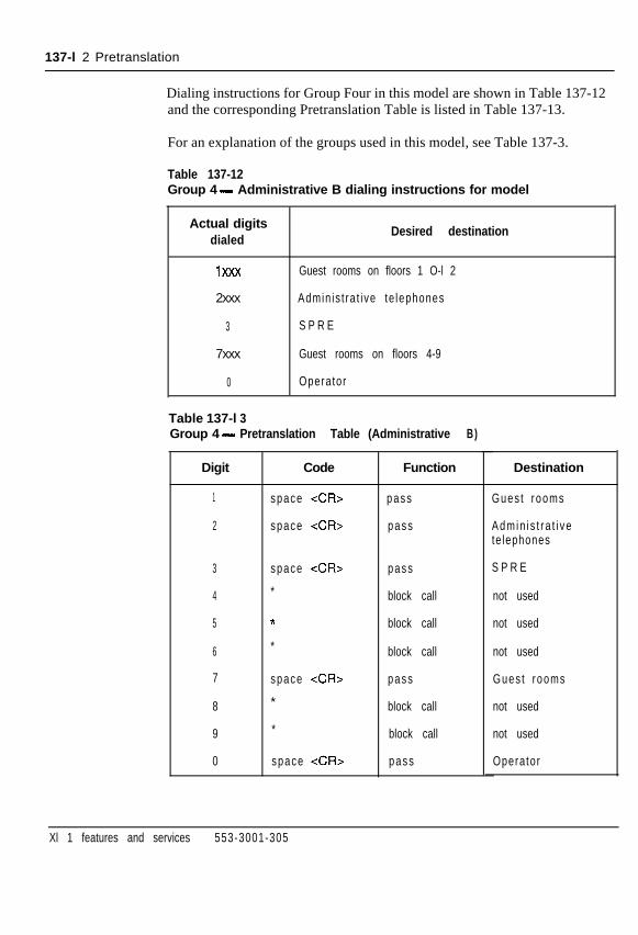
137-l 2 Pretranslation
Dialing instructions for Group Four in this model are shown in Table 137-12and the corresponding Pretranslation Table is listed in Table 137-13.
For an explanation of the groups used in this model, see Table 137-3.
Table 137-12Group 4 - Administrative B dialing instructions for model
Actual digitsdialed
Desired destination
1XXX Guest rooms on floors 1 O-l 2
2xxx Admin is t ra t ive te lephones
3 S P R E
7xxx Guest rooms on floors 4-9
0 Operator
Table 137-l 3Group 4 - Pretranslation Table (Administrative B)
Digit
1 space <CR> pass
2 space <CR> pass
3 space <CR> pass
4 * block call
5 * block call
6 * block call
7 space <CR> pass
8 * block call
9 * block call
0 space <CR> pass
Code Function Destination
Gues t rooms
Admin i s t ra t i vete lephones
S P R E
not used
not used
not used
Gues t rooms
not used
not used
Operator
Xl 1 features and services 553-3001-305

Pretranslation 137-l 3
Operating parametersThe following limitations apply to the Pretranslation feature:
- Pretranslat ion table codes are l imited to the four described previously.
- User groups are limited to 255 (8, before X11 release 14).
- Each pretranslation table entry can be up to 31 characters long, however,it is recommended that a maximum of 8 characters is used.
After pretranslat ion, any previously loaded (but not pretranslated) digitsare added to the end of the pretranslated digits . If the total number ofdigits exceeds 31, the excess digits will be truncated.
- Each Pretranslation table reduces the number of available Speed Calll i s t s in the sys tem.
- Speed Call Control lers do not have access to Pretranslat ion tables. Listsmust be created and maintained through service change.
Feature interactionsPretranslat ion cannot be used with the fol lowing features:
. Automatic Trunk Maintenance
. Private Line
. Telset Messaging
- Authorization CodeThe first digit dialed after a valid Authorization Code is sent to thepretranslator.
- Call Detail Recording (CDR)If a number dialed is pretranslated, the translated digits appear in theCDR records, not the dialed digits.
- Call ForwardThe DN dialed-forwarded calls are pretranslated.
- Charge AccountThe first digit dialed after a valid Charge Account Code is sent to thepretranslator.
Xl 1 features and services 553-3001-305

137-14 Pretranslation
- Digit DisplayThe Pretranslat ion digi t is displayed as i t was dialed, but i f fhe cal l is puton hold, the digits of the pretranslated DN are displayed.
-._
- Direct Inward System Access - DISA calls are automatically assignedXLST 0.
- Electronic Switched Network (ESN)The pretranslator is used with calls to HNPA, HLOC, and Home CDPlocat ions .
- Flexible Feature CodesFFC codes must be accessible through a Pretranslat ion Table entry inorder for users to activate features in this manner.
- Forced Charge AccountThe first digit dialed after a valid Charge Account Code is sent to thepretranslator.
- Meridian Link CallsPretranslat ion cannot funct ion with Meridian Link cal ls i f the Hospital i tyVoice Services (HVS) package is enabled.
- Special PrefixThe SPRE code must be accessible through a Pretranslat ion Table entryin order for users to activate features in this manner.
- Speed CallEntries must be accessible through a Pretranslat ion Table entry in orderto place a speed call .
Feature packagingPretranslation (PXLT), package 92 has no feature package dependencies.
Xi 1 features and services 553-3001-305

Pretranslation 137-15
LD17 - Allocate sufficient Speed Call l is ts to be used as Pretranslat ion Tables(Xl 1 release 13 and later software).
R E Q C H G Change
TYPE C F N Conf igura t ion record
M S C L (0)-8191 Maximum number of Speed Call lists
LD18 - Add or change a Speed Call list to be used for each Pretranslation calling group.
New or change
Speed Call data block
R E Q
TYPE
L S N O
N E W , C H G
S C L
O-81 90 Number of Pretranslation list
Note: With Xl 1 release 12 and earlier, up to 255 Pretranslationlists are allowed.
DNSZ
S I Z E
W R T
STOR
4-(16)-31
10
No, (Yes)
Number of digits that can be in a list entry
Maximum number of entries
W R T
STOR
X*
X-
x space <CR>
x YYYY...Y
No, (Yes)
< C R >
Data is correct and can be updated in data store
x is the first digit dialed
* = block call
* = delete the digit
space <CR> = pass digit unchanged
yyyy...y = replacement digits
Data is correct and can be updated in data store
Ends input of list entries
Feature implementation
Xl 1 features and services 553-3001-305
.:-.

137-16 Pretranslation
LD18 -Add or change the PTetTanslation data block, defining the calling group to Speed Call listcorrelation. This procedure is necessary in X11 release 14 and later software.
This list must be configured before Pretranslation (PREO) is enabled in LD15.
R E Q
TYPE :i
CUST
XLAT
N E W , C H G
P R E
o-99
xxx YYYY
New or change
Pretranslation (Xl 1 release 14 and later software)
Cus tomer number
Pretranslation list
xxx = Pretranslation calling group number (O-254)
yyyy = corresponding Speed Call list number(l-81 90)
Note: XLAT appears in LD1.5 in Xl 1 release 13 and earliersoftware.
LD15 -Activate Pretranslation and define calling groups to Speed Call list correlation.
R E Q
TYPE
CUST
P R E O
XLAT
C H G
C D B
o-99
0, 1
x YYYY
Change
Cus tomer Da ta B lock
Cus tomer number
Allow or deny Pretranslation
0 = no Pretranslation
1 = Pretranslation
Pretranslation list
x = Pretranslation calling group number (O-7)
yyyy = corresponding Speed Call list number(l-81 90)
Note: XlAT appears in LD18 in Xl 1 release 14 and latersoftware.
Xl 1 features and services 553-3001-305
.. .

Pretranslation 137-l 7
LDlO - Associate a 500/2500 telephone with a Pretranslat ion group.
R E Q
TYPE
T N
XLST
N E W , C H G
500
lscu
O-254
< C R >
New or change
Te lephone type
Termina l Number
Associate telephone with the specified Pretranslationgroup (O-7 in Xi 1 release 14 and earlier)
Default to Pretranslation group 0(only when REQ = NEW)
LDll - Associate a SL-1 or Meridian digi tal telephone with a Pretranslat ion group.
R E Q
TYPE
T N
XLST
N E W , C H G
aaaa
l s c u
O-254
< C R >
New or change
Te lephone type
aaaa = SLI, 2006,2008,2009,2016,2018,2112,2216,2317,2616,3000
Termina l Number
Associate telephone with the specified Pretranslationgroup (O-7 in Xi 1 release 14 and earlier)
Default to Pretranslation group 0 (only when REQ = NEW)
Feature operationThere is no specific procedure required to operate this feature.
Xl 1 features and services 553-3001-305

137-18 Pretranslation
Xl 1 features and services 553-3001-305

138-1
PrivacySL- 1 and Meridian digital telephones automatically provide Privacy fortelephones sharing a single call arrangement Directory Number (DN). Whena call is in progress on the DN, no other telephone on which the DN appearscan enter the call .
Operating parameters
Feature interactions- Privacy Override
The user can override the inherent privacy on SL-1 and Meridian digitaltelephones. If an appearance occurs on a telephone with PrivacyOverride enabled, that appearance can bridge into an active call. Thispertains to calls on a multiple appearance single call Directory Number(DN) when not mixed with single line telephones.
Feature packaging
Feature
Feature
Privacy is included in basic Xl 1 system software.
implementationNot applicable.
operation
Privacy is not available for 500/2500 telephones.
If the Directory Number (DN) is shared with any single line telephone,Privacy is not in effect for any appearance of the DN, and anyone sharing thatDN can enter an active call.
There is no specific procedure required to operate this feature.
Xl 1 features and services 553-3001-305

138-2 Privacy
Xl 1 features and services 553-3001-305

Privacy OverrideAn SL- 1 or Meridian digital telephone with a Privacy Override Allowed(POA) class of service can enter an established call on a multiple appearancesingle call Directory Number (DN). However, the call cannot be joined untilit is established (that is, the EOD timer has expired).
If all members of a non-mixed multiple appearance single call DN group areallowed Privacy Override, the operation of the feature is equivalent to amixed multiple appearance single call arrangement.
When a group contains a combination of Privacy Override Allowed (POA)and Privacy Override Denied (POD) classes of service, the telephones deniedPrivacy Override cannot bridge into established cal ls .
Operating parametersPrivacy Override does not apply to s ingle l ine telephones.
Xl 1 features and services 553-3001-305
.: ‘,

139-2 Privacy Override
Feature interactions- Exclusive Hold
Telephones with POA class of service cannot bridge into calls onDirectory Numbers (DNs) with Exclusive Hold active.
- Call TransferCalls in a Privacy Override conference state cannot be transferred.
- Call ParkCalls in an Privacy Override conference state cannot be parked.
- ConferenceThe Conference feature can be used to add other parties to a PrivacyOverride connection.
- Multiple Appearance DN, Mixed ModeSince the Privacy feature is not active in this mode, telephones with aPOD class of service can bridge into an active call.
Feature packagingPrivacy Override is included in basic X11 system software.
Feature implementation
LDll- Allow or deny Privacy Override on an SL-1 or digital telephone.
R E Q
TYPE
C H G
aaaa
Change
Te lephone type
aaaa = SLl ,2006,2008,2009,2016,2018,2l12,2216,2317,2616,3000
T N
CLS
lscu
POA, (POD)
Termina l Number
Allow or deny Privacy Override
Feature operationTo activate Privacy Override, press the multiple appearance single call DN.You are automatically connected to the call.
X1 1 features and services 553-3001-305

i ssued: ‘92 12 31Status: StandardXl 1 Release: Al l
140-l
Privacy ReleaseIn multiple appearance single call arrangements of SL- 1 and Meridian digitaltelephones, Privacy Release allows one other appearance of the DirectoryNumber (DN) to enter the call. Privacy is then reestablished until PrivacyRelease is activated again.
Operating parametersAvailable only with SL- 1 or Meridian digital telephones in multipleappearance single call arrangements.
The system must be equipped with a conference loop.
Feature interactions- Exclusive Hold
If the telephone with Privacy Release has Exclusive Hold Allowed in theclass of service, and a call is on hold, another telephone with thatMultiple Appearance Directory Number (MADN) cannot access the call .
Feature packagingPrivacy Release is included in basic XI 1 system software.
Xl 1 features and services 553-3001-305

140-2 Pr i vacy Re lease
Feature implementation
LDll-Allow/deny Privacy Release for SL-1 and Meridian digital telephones.
R E Q C H G
TYPE aaaa
Change
Te lephone type
aaaa = SLI ,2006,2008,2009,2016,2018,2112,2216,2317, 2616, 3000
T N
K E Y
l s c u
xx PRS
Termina l Number
Add a Privacy Release keyM2317 and M3000 telephones automatically assign thePRS key to key 28.
Feature operationTo allow someone with another appearance of the Directory Number (DN) toenter a call:
1 Press Priv Rls. All appearances of that DN flash. One other party canenter the cal l by pressing the f lashing DN key that has the cal l .
2 You must press Priv Rls again to allow another appearance of the DN toenter the call.
Xl 1 features and services 553-3001-305

Issued: 92 12 31Status: StandardXi 1 Release: All
141-l
Private Line ServicePrivate Line Service enables the customer to assign private Central Office(CO) lines to selected telephones or power fail transfer equipment. Whenassociated with an SL-1 or Meridian digital telephone, the following featuresare available to Private Line Service:
- Automatic Dialing
- Automatic Preselection
- Call Pickup
- Call Transfer
- Call Status
- Conference
- Common Audible Signaling
- Hold
- Multiple appearance single call arrangement
- Prime Directory Number
- Privacy
- Privacy Release
- Release
- 500/25OO/SL- 1 telephone mix
Xl 1 features and services 553-3001-305
. ..- :

141-2 Private Line Service
Operating parametersSingle l ine telephones with Private Line Service cannot access Meridian SL-1features.
All Private Lines must be assigned to trunk route 31 on X11 release 13 andearlier software. A Directory Number (DN) must be assigned to each trunk.
A maximum number of 126 Private Lines are available per customer.
X11 release 14 and later software allow 512 Private Line trunk routes to bedefined.
A Private Line should not be assigned as a prime Directory Number (DN)unless preselect ion is required.
Hunting does not apply to Private Line service.
Call Forward on Private Lines (SL-1 or Meridian digital telephones) is notforwarded to a second appearance of its own DN.
Feature interactionsCall Modification Features (CMF) in the trunk data block can be inhibited asfollows:
- Call Transfer
- Conference
- Call Forward
- Call Forward No Answer
- Message Center
- Call Forward No AnswerCall Forward No Answer is always inhibited on Private Lines.
- Multiple-appearanceFor multiple appearance calls, call modification cannot be blocked.
Feature packagingPrivate Line Service is included in basic Xl 1 system software.
Xl 1 features and services 553-3001-305
:.‘.

Private Line Service 141-3
Feature implementation
LD16- Add or change a Private Line trunk route.
R E Q
TYPE
CUST
R O U T E
T K T P
A U T O
ICOG
C H G
R D B
o-99
o-51 1
C O T
Yes, (No)
IA0
Change
Route Data Block
Cus tomer number
Route number
Central Office trunk
Trunks in this route autoterminate
Incoming and ou tgo ing rou te
LD14 - Add or change Private Line trunks in the Private Line trunk route.
R E Q N E W , C H G
TYPE C O T
T N l s c u
XTRK XUT. XEM
P R D N
C M F
xxx...x
Yes, (No)
New or change
Central Office trunk
Termina l Number
Universal Trunk Card (NT8D14), E&M Trunk Card(NT8D15). Prompted only for superloops and the first uniton the card.
Private Line phantom DN
Call modification is or is not inhibited for private line
LDlO - Add or change Private Line Service for 500/2500 telephones.
R E Q
TYPE
T N
D N
C H G
500
lscu
xxx...x
Change
Te lephone type
Termina l Number
Private Line DN (xxx...x is the same as for PRDN prompt inLD14)
Xl 1 features and services 553-3001-305
: .,

141-4 Private Line Service
LDll -Add or change Private Line Service for SL-1 Meridian digital telephones.
REQ
TYPE
i -_
T N
K E Y
C H G
aaaa
lscu
xx PVN yyy.. .y
xx PVR yyy...y
Change
Te lephone type
aaaa = SLl, 2006,2008,2009,2016,2018,2112,2216,2317,2616,3000
Termina l Number
Private Line non-ringing key (yyy...y is the same as forPRDN prompt in LDl4)
Private Line ringing key (yyy...y is the same as for PRDNprompt in LD14)
Feature operationThere is no specific procedure required to operate this feature.
Xi 1 features and services 553-3001-305

142-1
Property Management System InterfaceThe Property Management System Interface (PMSI) is a full-duplex RS-232asynchronous data link that allows a Meridian 1 customer with a PropertyManagement System (PMS) computer to exchange a higher level of protocolfor the Background Terminal (BGD) features in a hospitality environment.
The Meridian 1 sends formatted messages to the Property ManagementSystem (PMS) computer for the following features:
- Controlled Class of Service (CCOS)
- Message Waiting
- Do Not Disturb (DND)
- Room Status (RMS)
- Call Number Information Messages (CMIN)
- Call Party Name Display (CPND)
The system connects to the Property Management System (PMS) computerthrough a Serial Data Interface (SDI) port. Each character received from theProperty Management System Interface (PMSI) data link is treated as if itwere entered from a TTY, and each character transmitted to the PMScomputer is handled the same way as characters output to a TTY.
Xl 1 features and services 553-3001-305

142-2 Prope r t y Managemen t Sys tem In te r face
PMSI StandardizationThe PMSI Standardization features in X11 release 19 and later provide theMeridian 1 with the following enhancements:
t,- _- Message retransmission
- Polling
- Message monitoring
Note: Upon loading Xl 1 release 19, these features are not automaticallyactivated. You must go into LD17 to enable these features.
Message transmission and retransmissionPrior to X11 release 19, the Meridian 1 ignored any response returned by thePMS after sending a room status message to the PMS, and did not a t tempt toretransmit the message. As a result , the database between the PMS and theMeridian 1 could not be maintained consis tent ly .
With X11 release 19 and later, PMSI Standardization provides the Meridian1 with the capability to retransmit a message to the PMS. This means that,whenever the Meridian 1 transmits a room message or the new pollingmessage to the PMS, the Meridian 1 will wait for an <ACK> response fromthe primary PMSI port. If the Meridian 1 receives a <NAK>, or does notreceive any response before the predefined response timer expires, the samemessage will be retransmitted to the primary PMSI port.
PollingPrior to X11 release 19, the Meridian 1 did not have the capability to monitorthe status of the PMSI link (that is, the link between the Meridian 1 and thePMS).
With X11 release 19 and later, PMSI Standardization provides thismonitoring capability by enabling the Meridian 1 to poll the PMSI link atpredefined intervals.
Xl 1 features and services 553-3001-305

Proper t y Management Sys tem in te r face 142-3
Message monitoringPrior to X11 release 19, the Meridian 1 did not have the capability to trackincoming messages f rom the PMS or outgoing messages to the PMS.
With Xl1 release 19 and later, PMSI Standardization provides this trackingcapabil i ty by enabling these incoming/outgoing messages between theMeridian 1 and the PMS to be displayed on al l maintenance (MTC) lTYs onthe Meridian 1.
Refer to Property Management System Interface descript ion (553-2801-101)for detailed information on PMSI Standardization.
Operating parametersRefer to Property Munagement System Inte$ace descript ion (5.53-2801-101).
Feature interactionsRefer to Property Managemerzt System Inte$ace description (553-2801-101).
Feature packagingProperty Management System Interface (PMSI), package 103, requires:
- Controlled Class of Service (CCOS), package 81
- Room Status (RMS), package 100
- Background Terminal (BGD), package 99
Note: PMSI Standardization requires release 19 software. I
Feature implementationRefer to Property Management System Inter$ace descript ion (553-2801-101).
Feature operationThere is no specific procedure required to operate this feature.
Xi 1 features and services 553-3001-305
.-~ .

142-4 Proper t y Management Sys tem in te r face
Xl 1 features and services 553-3001-305
-:, .- ._ : ’ :: :-.,.,..; , :;,I.~

Public Switched Data ServiceThe Public Switched Data Service (PSDS) al lows you to receive data on yourMeridian 1 at 56 kbps over Digital Trunk Interface (DTI) trunks (with Xl 1release 16 and later), and at 64 kbps over an Integrated Services DigitalNetwork (ISDN) Primary Rate Interface (PRI) channel (with Xl 1 release 18and later). See Figure 143-1.
Figure 143-lPublic Switched Data Service (PSDS) between Meridian 1 and CentralOff ice (CO)
Mer id ian0 1
Cent ra l0Off ice
You can install a Tl link to different vendors and use the MeridianCommunications Adapter (MCA) or QMT21 high speed data module toinit iate or receive a 56 kb digital data call . The digital data call then transportsacross the vendor’s digital network to another Meridian 1 or an SL- 100.
Xl 1 features and services 553-3001-305
:.: .. ..::

143-2 Public Switched Data Service
Note I: Public Switched Data Service (PSDS) requires X11 release 16or later. The various data modules are supported for different releases.
Note 2: The Meridian Communications Adapter (MCA) operates withX11 release 16 and later. The QMT21 module operates with X11 releases16 and 17.
Operating parametersPSDS calls are supported in the following situations:
- an SL-1 and the Central Office (CO)
- a tandem call from an SL-100 to an SL-1
- an SL-1 and other PSDS-compatible switches
The PSDS supports Digital Trunk Interface (DTI)-type trunks, tie andDID/DOD trunks, and Electronic Tie Network (ETN)-compatible signaling.
End to End DTI networkFor all SL-1 networks (Point to Point), users can access the existing datafacility in the SL-1 to support data calls, or they can select the Switched 56data mode. For mixed vendors private networks, users can only select thePSDS mode.
Feature interactionsISDN PRI - The following routes are possible using this feature on PrimaryRate Access:
- Point to point accessFor point to point access of tie trunks, the software can be modified tohandle the requirements of this feature.
- Tandem callFor tandem access, additional information on this feature is needed, orthe data call can be defined as a voice call.
- DIDIFEX/WATS/AccunetThe Meridian 1 supports PSDS data cal ls to these t runk types.
- Public Network hop offSignaling is provided to inform the tandem switch about the PSDS datacall.
Xi 1 features and services 553-3001-305
/_

Public Switched Data Service 143-3
Feature packagingPSDS is included in basic X11 system software.
Feature implementationThe data selection (DSEL) in the Route Data Block can be defined as voicecalls only (VCE), data calls only (DTA), or voice and data calls (VOD). Thecall can be defined as voice calls, regular data calls, or PSDS calls. Refer toXl I input/output guide (553-3001-400) to configure the Route Data Block.
Feature operationOriginating data callsFor direct access, dial the regular 7-digit or lo-digit number.
For special route access, dial a route access code after hearing a dial tone.
Receiving data callsCalls are answered automatically.
An auto answer call is answered by the data module, and no special operationis necessary.
Related FeaturesWhen using PSDS, you may want to refer to the following features.
Meridian Communications Adapter (MCA)The Meridian Communications Adapter MCA operates with X11 release 16and later and allows asynchronous ASCII terminals, personal computers, andprinters to be connected to the telephone using an RS-232-C or V.35interface. With release 14 and later, the MCA also allows synchronousapplicat ions (DTEs such as, video conferencing equipment and Group 1V faxunits) to be connected to the telephone. Refer to Meridian Communicat ionsUnit and Meridian Communications Adapter (553-2731-109) for detailedinformation on the MCA.
Xl 1 features and services 553-3001-305
.::
143-4 Public Switched Data Service
Meridian Communications Unit (MCU)The Meridian Communications Unit (MCU) is a release 19 feature thatprovides a stand-alone version of the Meridian Communications Adapter(MCA).
The Meridian Communications Unit (MCU) allows you to transmit andreceive data using ei ther PSDS over the public network or a private network.The MCU, which replaces the QMT21C, is designed for domestic andinternational use, with transmission speeds up to 19.2 Kbps asynch, and 64Kpbs synch, integrated display, and self diagnostics. The MCU supportsautodialing, r ing again, and speed call ing, as well as autobauding andautomatic parity detection. You can use the MCU for
- Video conferencing
- LAN bridging
- Bulk data/PC file transfer
- Dial back-up
- Host connectivity
The MCU fully complies with RS-232C and can be configured as DCE orD’FE to connect to a terminal, printer, or fax machine.
Unlike the MCA, the MCU provides a dedicated call key and call progresstones. The MCU also permits smart modem pooling.
The MCU supports the DM-DM, T-Link, V.2.5 bis, and PSDS interfaces aswell as the RS-232C, CCI’lT V.35, CCI’IT V.24, and RS570/RS3449 (withdifferent cables) interfaces. It complies with V.28 for European approval.
Refer to Meridian Communicat ions Uni t and Meridian Communicat ionsAdapter descr ip t ion , ins ta l la t ion , adminis t ra t ion , and opera t ion(553-2731-109) for detailed information on this feature.
Xl 1 features and services 553-3001-305
.:: . .

Public Switched Data Service 143-5
Transparent Data Networking (TDN)Transparent Data Networking is an Xl1 release 19 feature that provides atransparent data channel for data modules to perform end-to-end protocolexchange. This means that two data modules wil l wait for a circuit path to beestablished before exchanging protocol parameters.
The data modules and protocols that are supported by TDN are:
- Meridian Communications Adapter (MCA) card in a Meridian Modulartelephone (MMT) set . Uses PSDS and T-Link protocols on external cal ls
- Meridian Communications Unit (MCU) - a stand-alone- version of theMCA. Uses T-Link and PSDS protocols on external calls.
- Basic Rate Interface (BRI) telephones. Use T-Link, V.110, and V.120protocols .
- High Speed Data Module (HSDM). When configured to use PSDS.
Refer to Transparent Data Networking (553-2731-110) for detailedinformation on TDN.
Xl 1 features and services 553-3001-305

143-6 Public Switched Data Service
Xi 1 features and services 553-3001-305
. . . .
:I
_.
‘.
92 12 31Standard
Al l
Recorded Announcement144- l
The Recorded Announcement (RAN) feature allows the Meridian 1 toconnect calls automatically to a customer-provided recorded announcementmachine. Recorded Announcements can be used for:
- Automatic Call Distribution (ACD)
- Automatic Wake Up
- Intercept Treatment (INTR)
- Recorded Overflow Announcements (ROAs)
The system software detects calls to connect to the Recorded Announcement(RAN) machine, determines the Intercept Treatment required, and connectsthe call to the proper recorded announcement. The system then monitors theRAN machine.
The Meridian 1 provides the software programs to control the announcementrecorder and the circuit packs. Two types of circuit packs can be used:
- Recorded Announcement (RAN) Trunk Cards (QPC74) contain fouridentical trunk circuits for the interface between the Meridian 1 and theannouncement machine. See QPC74 Recorded Announcement TrunkCard description (553-2201-194) for engineering information. Whenusing the QPC74, all ports on the card must be dedicated as TYPE RANor TYPE MUS.
- Universal Trunk Cards (NT8D 14AA) contain eight identical trunkcircuits that can be configured independently in the system software. SeeNT8D14 Universal Trunk Card description (553-3001-171) for adescr ipt ion.
Xi 1 features and services 553-3001-305

144-2 Recorded Announcement
Operating parametersDial access to RAN trunk groups is allowed and is limited only.by TrunkGroup Access Restr ict ions (TGARs).
Feature interactionsWhen using the QPC74, all ports on the card must be dedicated as TYPERAN or TYPE MUS.
Feature packagingRecorded Announcement (RAN), package 7, requires:
- Intercept Treatment (INTR), package 11
Feature implementation
LD16- Add or change Recorded Announcement (RAN) trunk route. (Part 1 of 2).
R E Q N E W , C H G
TYPE RDB
GUST o-99
R O U T O-511
TKTP RAN
RTYP C A P
A U D
New or change
Route Data Block
Cus tomer number
Route number
RAN t r unks
Code-a-Phone record ing dev ice . Sof tware a l lowsannouncements of up to 320 seconds in length in Xi 1release 14, or 608 seconds in Xi 1 release 15.
Audichron recording device (required when connecting to aUniversal Trunk Card). Software allows announcements ofup to 64 seconds.
CK2 Cook Electric recording device. Software allowsannouncements of up to 64 seconds.
Xl 1 features and services 553-3001-305

Recorded Announcement 144-3
LD16-Add or change Recorded Announcement (RAN) trunk route. (Part 2 of 2).
R E P
P O S T
S T R T
ASUP
ACOD
D G T
C O N
1-15
A T T
D I S
IMM
D D L
Yes, (No)
xxx...x
Digital Recorders 213300 & 213400. Software allowsannouncements of up to 256 seconds on Xl 1 release 15and later.
NT7M series digital recorders. Software allowsannouncements of up to 608 seconds on Xl 1 release 15and later.
Number of times the announcement repeats during eachconnec t ion
Call is routed to attendant after specified number ofrepetitions (applies to Direct Inward Dial (DID) calls onIntercept)
RAN is removed after a specified number of repetitions
Ca l l connec ts immed ia te ly to announcement
Call connects to announcement at the start ofannouncement
Supervision is or is not required to inform the Central Office(CO) when the call is answered
Trunk route access code
Note: All RAN route members must be removed before the route can be removed.
LD14 -Add or change Recorded Announcement (RAN) trunk.
R E Q
TYPE
T N
CUST
R T M B
N E W , C H G
RAN
l s c u
o-99
xxx YYY
New or change
RAN trunk data block
Termina l Number
Cus tomer Number
Prompted if REQ = NEW
Route and member number
xxx = o-511
yyy = i-254
Xl 1 features and services 553-3001-305

144-4 Recorded Announcement
Feature operationThere is no specific procedure required to operate this feature.
Xl 1 features and services 553-3001-305

Recorded Overflow AnnouncementRecorded Overflow Announcement (ROA) allows delayed calls to theattendant to be connected to a recorded announcement notifying the call ingparty of the delay. A second recorded message can also be provided to thecall ing party repeatedly unti l an at tendant answers the call .
A call that is waiting in the queue receives the first recorded message after theexpiration of a timer (Tl). After the message is given, the call returns to theattendant queue. While the call is in the wait ing state, i t can be connectedeither to Music (MUS), Ringback tone (RGB), or Silence (SIL).
If a second recorded announcement is specified, the call receives the messageupon expiration of a second timer (T2). After the second message is given,the cal l is placed in the at tendant queue again. There is no l imit to the numberof times a call can be given the second recorded message.
Operating parametersRecorded Overflow Announcement (ROA) treatment is provided to call typesassigned to Incoming Call Indicator (ICI) keys on the at tendant console.
A maximum of 20 ICI keys can be assigned to receive Recorded OvefflowAnnouncement (ROA) treatment.
Xl 1 features and services 553-3001-305
: ‘.. .
..: :. :

145-2 Recorded Over f low Announcement
The delay t ime thresholds for the first and second recorded announcements(Tl and T2) are assigned in LD15. The following thresholds can be definedfor these timers.
Table 145-lDelay time thresholds
Thresholds
Ti
T 2
Minimum Default
0 seconds 20 seconds
0 seconds 40 seconds
Maximum
2,044 seconds
2,044 seconds
Loop star t t runks do not provide disconnect supervision and are notrecommended for use with the ROA feature. A call on a loop start trunk thatis abandoned after the recorded message is given must be manually clearedby the at tendant .
ROA is not provided on release link trunks from Centralized AttendantService (CAS) remote locations.
When the CAS feature is activated at a remote PBX, the ROA feature isinactive at the remote site.
If music is required, the Music (MUS) package must be equipped. Music canbe provided after the f irs t and second Recorded Announcement (RAN). Acustomer provided music source is required, connected through a musictrunk. Music is provided to delayed calls through a conference circuit pack ina listen-only mode. The music source provided by the customer must becompatible with the RAN trunk card.
Prior to X11 release 15, Music (MUS) and Recorded Announcement (RAN)cannot share the same trunk card.
Private Lines are not eligible for ROA.
Xi 1 features and services 553-3001-305

Recorded Over f low Announcement 145-3
Feature interactionsROA is only provided for cal l types assigned to Incoming Call Indicator (ICI)keys. The following call types are eligible, if related ICI keys are assigned:
- Trunk routes
- LDN 0 through LDN 3
- Dial 0
- Dial 0 Fully Restricted
- Intercept Treatment (INTR)
- Call Forward Busy
- Call Forward No Answer
- Message Waiting (MW)
- Lockout
- Station Category Indication (SCI)
- Night ServiceThe ROA feature is inactive when the system is in Night Service.
- Automatic Call Distribution (ACD)The RAN route used for ROA may be the same route that is used forACD and Intercept Treatment.
Feature packagingRecorded Overflow Announcement (ROA), package 36, requires:
- Recorded Announcement (RAN), package 7
Xl 1 features and services 553-3001-305
.‘.X:

145-4 Recorded Over f low Announcement
Feature implementation
LD16 - Add or change Recorded Announcement (RAN) trunk route.
R E Q N E W , C H G New or change
TYPE -- R D B Route Data Block
CUST o-99 Customer number
R O U T o-51 1 Route number
T K T P RAN RAN t r unks
RTYP C A P Code-a-Phone record ing dev ice
A U D Audichron recording device (required when connecting to aUniversal Trunk Card)
CK2 Cook Electric recording device
D G T Digital Recorders 213300 & 213400. Allowsannouncements of up to 192 seconds on Xi 1 release 15and later software.
CON NT7M series digital recorders. Allows announcements of upto 512 seconds on Xl 1 release 15 and later software.
R E P 1 - 1 5 Number of times announcement is repeated during eachconnec t ion
P O S T ATT Call is routed to attendant after specified number ofrepetitions (applies to Direct Inward Dialing (DID) calls onIntercept)
S T R T
D I S
IMM
D D L
RAN is removed after specified number of repetitions (callkeeps its place in Automatic Call Distribution (ACD) queue)
Ca l l connec ts immed ia te ly to announcement
Call connects to announcement at the start ofannouncement
ASUP Yes (No) Supervision is or is not required to inform the Central Office(CO) when the call is answered
ACOD xxx...x Trunk route access code
Note: All RAN route members must be removed before the route can be removed.
Xl 1 features and services 553-3001-305
:.. . .:
. . ,
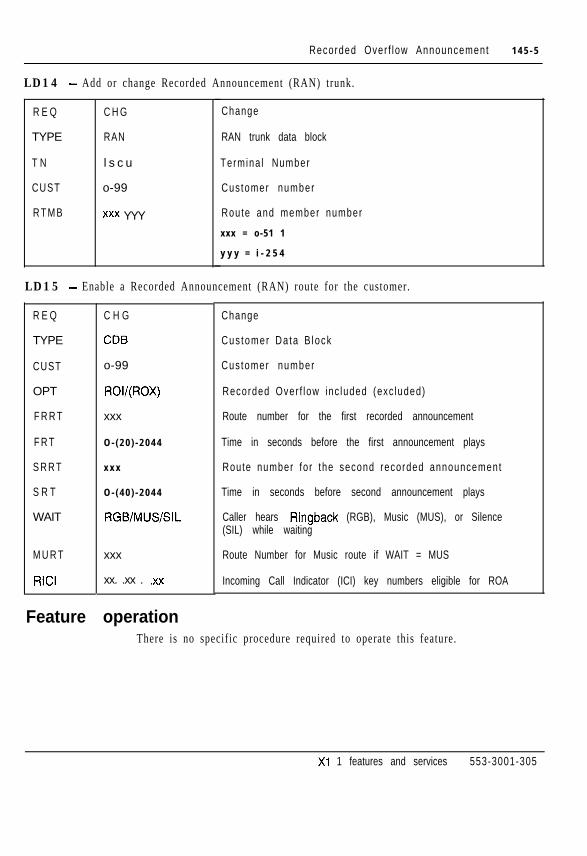
Recorded Over f low Announcement 1 4 5 - 5
LD14 - Add or change Recorded Announcement (RAN) trunk.
R E Q
TYPE
T N
CUST
R T M B
C H G
RAN
l s c u
o-99
xxx YYY
Change
RAN trunk data block
Termina l Number
Cus tomer number
Route and member number
xxx = o-51 1
y y y = i - 2 5 4
LD15 - Enable a Recorded Announcement (RAN) route for the customer.
R E Q
TYPE
CUST
OPT
F R R T
F R T
S R R T
S R T
WAIT
M U R T
RICI
C H G
CD6
o-99
ROI/(ROX)
xxx
O - ( 2 0 ) - 2 0 4 4
x x x
O - ( 4 0 ) - 2 0 4 4
RGB/MUS/SIL
xxx
xx. .xx . .xx
Change
Cus tomer Da ta B lock
Cus tomer number
Recorded Over f low inc luded (exc luded)
Route number for the first recorded announcement
Time in seconds before the first announcement plays
Route number fo r the second recorded announcement
Time in seconds before second announcement plays
Caller hears Ringback (RGB), Music (MUS), or Silence(SIL) while waiting
Route Number for Music route if WAIT = MUS
Incoming Call Indicator (ICI) key numbers eligible for ROA
Feature operationThere is no specific procedure required to operate this feature.
Xl 1 features and services 553-3001-305

145-6 Recorded Over f low Announcement
Xl 1 features and services 553-3001-305

I I s s u e d : . 92 12 31Status: StandardXl 1 Release: Al l
146-1
Recorded Telephone DictationThis feature provides dial access to customer supplied dictat ion equipment.Operation of the equipment can be either voice- or dial-controlled. The actualcontrols vary with the type of dictat ion equipment used.
To access the dictation equipment, the user dials the access code assigned tothe dictat ion route. Access to the route is controlled by Trunk Group AccessRestrictions (TGARs).
Operating parametersEach recorded dictation unit requires a separate trunk route.
Feature interactionsThere are no feature interactions.
Feature packagingRecorded Telephone Dictation is included in basic Xl 1 system software.
Xl 1 features and services 553-3001-305

146-2 Recorded Te lephone D ic ta t ion
Feature implementation
LD16 - Add or change a trunk route for the Recorded Telephone Dictation feature.
R E Q
TYPE
CUST
R O U T
TKTP
ICOG
ACOD
C H G
R D B
o-99
o-51 1
D I C
OGT
xxx...x
Change
Route Data Block
Cus tomer number
Route number
Recorded Telephone Dictation trunk route
Outgo ing t runk rou te
Directory Number (DN) to dial to access the dictationd e v i c e
LD14 - Add or change a trunk for the Recorded Telephone Dictation feature.
R E Q
TYPE
T N
CUST
R T M B
SIGL
S T R O
SUPN
C H G
R D B
l s c u
o-99
rrr mm
aaa
aaa
Yes, (No)
Change
Route Data Block
Termina l Number
Cus tomer number
Route and member number
Trunk s igna l ing
Outgo ing s tar t a r rangement
Answer and d isconnect superv is ion requ i red
Feature operationThere is no specific procedure required to operate this feature.
X1 1 features and services 553-3001-305

Issued: 93 08 01Status: StandardXl 1 Release: 1 5
147-1~-
Remote Call ForwardRemote Call Forward (RCFW) allows a telephone user to program CallForward from a remote telephone. With Remote Call Forward (RCFW)enabled, forwarding DNs can be defined and Call Forward All Calls activatedfrom within the Meridian 1 or outside the local switch. The Remote CallForward (RCFW) feature is password protected.
The Station Control Password (SCPW) is required to program Remote CallForward. Entering a password length of 0 disables the password control forboth Electronic Lock and RCFW.
Operating parametersRCFW requires the following:
- set the password length in LDl5, at the SCPL prompt
- add passwords in LD 10 and LD 11, at the SCPW prompt
- allow Call Forward All Calls in LD 10 and LD 11
- define Remote Call Forward Activate (RCFA), Deactivate (RCFD), andVerify (RCFV) Flexible Feature Codes (FFC) in LD57
To activate RCFW from outside of the local switch, you must use the DirectInward System Access (DISA) DN. The telephone’s Prime DN is associatedwith the RCFW password for added security. Also, RCFW can activate ordeactivate Call Forward on a telephone, and verify the same feature on atelephone.
Xi 1 features and services 553-3001-305

147-2 Remote Ca l l Fo rward
If there are two telephones with the same Prime DN, it is recommended thatonly one of them have a Sta t ion Control Password. With RCFW, i t i s possiblethat two telephones could have the same password assigned. With the samepassword, they could control each other’s security. For the same reason, theSecondary DN for an ACD telephone should not appear as a Prime DN onanother telephone.
Changes to the Stat ion Control Password length do not take affect unt i l af tera data dump and sysload.
Refer to “Flexible Feature Codes” on page 82-1 for additional information.
Operating parametersRCFW is not supported for ACD telephones.
Feature interactionsAttendant Adminis t ra t ion - Attendant Adminis t ra t ion does not support thetelephone programming associated with Remote Call Forward.
Feature packagingThe following software packages are required to implement Remote CallForward:
- Extended PBX Features (OPTF), package 1
- Flexible Feature Codes (FFC), package 139
- Controlled Class of Service (CCOS), package 81
The following software packages are required to implement RCFW on500/2500 telephones.
- 2500 Telephone Features (SS2.Q package 18
- 500 Telephone Features (SS5), package 73
Xi 1 features and services 553-3001-305
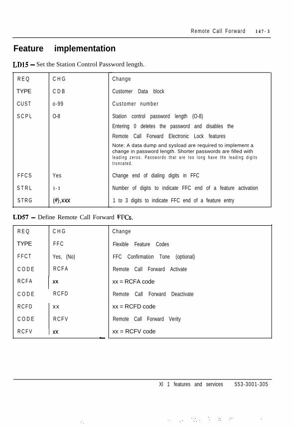
Remote Ca l l Fo rward 147-3
Feature implementation
LD15 - Set the Station Control Password length.
R E Q
TYPE
CUST
S C P L
F F C S
S T R L
S T R G
C H G
C D B
o-99
O-8
Yes
1-3
(8 ,xXx
Change
Customer Data block
Cus tomer number
Station control password length (O-8)
Entering 0 deletes the password and disables the
Remote Call Forward Electronic Lock featuresNote: A data dump and sysload are required to implement achange in password length. Shorter passwords are filled withl e a d i n g z e r o s . P a s s w o r d s t h a t a r e t o o l o n g h a v e t h e l e a d i n g d i g i t st r u n c a t e d .
Change end of dialing digits in FFC
Number of digits to indicate FFC end of a feature activation
1 to 3 digits to indicate FFC end of a feature entry
LD57 - Define Remote Call Forward FFCs.
R E Q
TYPE
F F C T
C O D E
R C F A
C O D E
R C F D
C O D E
R C F V
C H G
F F C
Yes, (No)
R C F A
Ixx
R C F D
xx
R C F V
I xx-
Change
Flexible Feature Codes
FFC Confirmation Tone (optional)
Remote Call Forward Activate
xx = RCFA code
Remote Call Forward Deactivate
xx = RCFD code
Remote Call Forward Verity
xx = RCFV code
Xl 1 features and services 553-3001-305
.’ . .
_, .- ..,y. .: :.. .-. . . -.

147-4 Remote Ca l l Fo rward
LDlO - Set the Station Control Password for single line telephones and allow Call Forward.
R E Q
TYPE
T N
SCPW
F T R
C H G
500
l s c u
xxx...x
X
CFW 4-(16)-23
Change
Te lephone type
Termina l Number
Station control password (O-8 digits as defined by promptSCPL in LDI 5)
Entering X deletes the password
Allow Call Forward and set forwarding DN length.
LDll - Set the Station Control Password for SL-1 and Meridian digital telephones and allow CallForward.
REQ
TYPE
T N
SCPW
KEY
C H G
aaaa
l s c u
xxx...x
X
xx CFW 4-(16)-23
Change
Te lephone type
aaaa = SLI, 2006,2008,2009,2016,2018,2112,2216,2317, 2616, 3000
Termina l Number
Station control password (O-8 digits as defined by promptSCPL in LD15)
Entering X deletes the password
Assign Call Forward key (xx) and set forwarding DN length.
Xi 1 features and services 553-3001-305

Remote Ca l l Fo rward 147-5
Feature operationFrom any telephone within the system, s imply l i f t the handset and use thefollowing procedures. From any telephone outside the s y s t e m , f i rs t dial theDirect Inward System Access (DISA) number for your system, wait for dialtone and dial any required passwords and Authorizat ion Codes.
1 Dial the Remote Call Forward Activate FFC.
2 Dial the Station Control Password for the telephone to be forwarded.
3 Dial the Prime DN of the telephone to be forwarded.
4 Dial the number to which calls will be forwarded.
5 Dial the end-of-entry digits (defined in LD15).
To cancel Remote Call Forward:
1 Dial the Remote Call Forward Deactivate FFC.
2 Dial the Station Control Password for the telephone.
3 Dial the Prime DN of the telephone.
To verify Remote Call Forward:
1 Dial the Remote Call Forward Verify FFC.
2 Dial the Station Control Password for the telephone.
3 Dial the Prime DN of the telephone.
4 Dial the number to which calls will be forwarded.
5 Dial the end-of-entry digit(s).
If the number you are forwarding calls to does not match your entry in step 4,you will hear a fast busy signal. You will hear a confirmation tone afterentering the forward number if they do match and confirmation tone isenabled in LD57.
Xl 1 features and services 553-3001-305
:..-

147-6 Remote Ca l l Fo rward
Xl 1 features and services 553-3001-305
. - . .

Issued:. 921231Status: StandardXi 1 Release: Al l
148-I
Remote Peripheral EquipmentThe Remote Peripheral Equipment (RPE) feature allows the range of themultiplexed loop between common and peripheral equipment to be extendedbeyond the normal 14 m (50 ft.), to about 100 km (70 miles) using Tl carrierfacilities. This carrier system must conform to North American Tlspecification to link the local and remote locations, and can consist of thefollowing:
- 24-gauge wire pairs for applications in which the remote end is less than2500 feet from the Meridian SL- 1 common equipment
- A Digital carrier link (such as Northern Telecom LD- 1)
- A microwave radio link
The Remote Peripheral Equipment (RPE) feature allows the peripheralequipment to be placed closer to the stat ions i t serves, and increases theserving area of a single system.
Among the benefits are the following:
- Normal attendant operation covering all locations
- Elimination of Tie lines between locations
- Uniform system features
- A fully integrated numbering plan
For details regarding RPE, refer to Northern Telecom Publication RemotePeripheral Equipment descr ipt ion, ins tal la t ion and tes t ing (553-2601-200).
Xl 1 features and services 553-3001-305

148-2 Remote Per iphera l Equipment
Operating parametersRefer to Remote Peripheral Equipment descript ion, ins tal lat ion and tes t ing(553-2601-200).
Feature interactionsRefer to Remote Peripheral Equipment descript ion, ins tal lat ion and tes t ing(553-2601-200).
Feature packagingRemote Peripheral Equipment (RPE), package 15, has no feature packagedependencies.
Feature implementationIf an even-numbered Tone and digit Switch (TFS), (CONF) or (MFSD) loop(0,48,72, 150) is equipped, the succeeding odd-numbered loop (1,49, 73,151) cannot be assigned as a voice loop.
The Peripheral Buffer card switch must be set for quad density. After changesare made, the system must be ini t ial ized to activate the changes to the networkloop in the database.
LDl7-Add or change a voice/RPE loop(s) (Part 1 of 2).
REQ
TYPE
CEQU
M P E D
TERM
C H G
C F N
Yes, (No)
SD, DD, 4D
- YYY
Change
Configuration data block
A l low changes to common equ ipment parameters
Max imum per iphera l equ ipment dens i ty
Single density local terminal loops
For nonenhanced ne tworks
xxx yyy = o-79 o-79
For enhanced ne tworks
xxx yyy = o-159 o-159
Xi 1 features and services 553-3001-305

Remote Per iphera l Equipment 148-3
LD17 - Add or change a voice/RPE loop(s) (Part 2 of 2).
REM0 xxx YYY Single density remote terminal loops
xxx yyy = o-79 o-79
For enhanced ne tworks
xxx yyy = o-1 59 o-1 59
T E R D xxx YYY Double density local terminal loops
For nonenhanced ne tworks
xxx yyy = o-79 o-79
For enhanced ne tworks
xxx yyy = o-1 59 o-1 59
R E M D xxx YYY Double density remote terminal loops
For nonenhanced ne tworks
xxx yyy= o-79 o-79
For enhanced ne tworks
xxx yyy = o-159 o-159
T E R Q xxx YYY Quad density local terminal loops
For nonenhanced ne tworks
xxx yyy= o-79 o-79
For enhanced ne tworks
xxx yyy = o-1 59 o-159
R E M Q xxx YYY Quad density remote terminal loops
For nonenhanced ne tworks
xxx yyy = o-79 o-79
For enhanced ne tworks
xxx yyy = o-159 o-1 59
Feature operationThere is no specific procedure required to operate this feature.
Xi 1 features and services 553-3001-305
:

148-4 Remote Per iphera l Equipment
Xl 1 features and services 553-3001-305
._. _ /. , . , - ;: ;,;. :’ .‘.. ,._. ‘_.

Ring AgainRing Again gives you the opportunity, after encountering a busy DirectoryNumber (DN), to ring the DN again when it becomes free. If a dialed DN isbusy, or if al l the trunks are busy, pressing the Ring Again key asks the systemto monitor the dialed DN or trunk. When it becomes available, the systemnotifies you. The call is automatically dialed again when you press the RingAgain key a second time.
When the system aler ts you to r ing again, you have a l imited amount of t imeto respond. 500/2500 telephones have 6 seconds, while SL-1 and digitaltelephones have 30 seconds.
Operating parametersA key/lamp pair must be assigned to SL- 1 and digital telephones for RingAgain. M3000 and M23 17 telephones access Ring Again with a soft key.
Several people can act ivate Ring Again against the same DN while i t is busy.When the DN becomes free, the system notifies the first person in line.
For 500/2500 telephones, a Special Prefix (SPRE) or Flexible Feature Code(FFC) may be used.
Feature interactionsBasic/Network Alternate Route Selection (BARSmARS)
If the system is equipped with BARS or NARS, the Ring Again feature isused with the Call Back Queueing option to queue for outgoing trunks.
Xl 1 features and services 553-3001-305

1 4 9 - 2 Ring Again
Feature packagingRing Again is included in Extended PBX Features (OPTF), package 1, andhas no feature package dependencies.
Feature implementation
LDlO- Add or change Ring Again for s ingle l ine telephones.
R E Q C H G Change
TYPE 5 0 0 Single l ine te lephone
T N l s c u Termina l Number
CLS XRA, (XRD) Ring Again is allowed or denied
LDll -Add or change Ring Again for SL-1 and Meridian digital telephones.
R E Q C H G Change
TYPE aaaa Telephone type
aaaa = SLI, 2006,2008,2009,2016,2018,2112,2216,2 3 1 7 , 2616,300O
T N l s c u Termina l Number
KEY xx RGA Ring Again key
xx = key number (must be key 27 for M2317 or M3000)
Xi 1 features and services 553-3001-305
.. I ‘_.’ -...y: ,:..: -,;’ . ,,. :: ,:.- ..z., .i..:;,+ ~ :-..; -,

Ring Again 149-3
Feature operationRing Again is s l ightly different for each telephone type. Be sure to fol low thecorrect operat ing instruct ions.
SL-1 and Meridian digital telephonesTo activate Ring Again after hearing a busy signal:
1 Press Ring Again.
2 Hang up, or press F&S.
3 When you hear the Ring Again tone, l if t the handset or select a free DN.
4 Press Ring Again. The number is automatically dialed.
To cancel Ring Again:
- Press Ring Again before you hear the notification tone.
M3000TouchphoneTo activate Ring Again after hearing a busy signal:
1 Press Ring Again.
2 Hang up, or press RLS.
3 When you hear the Ring Again tone, l if t the handset or select a free DN.
4 Touch Connect. The number is automatically dialed.
To cancel Ring Again:
- Press Ring Again before you hear the notification tone.
Xl 1 features and services 553-3001-305
. - . .
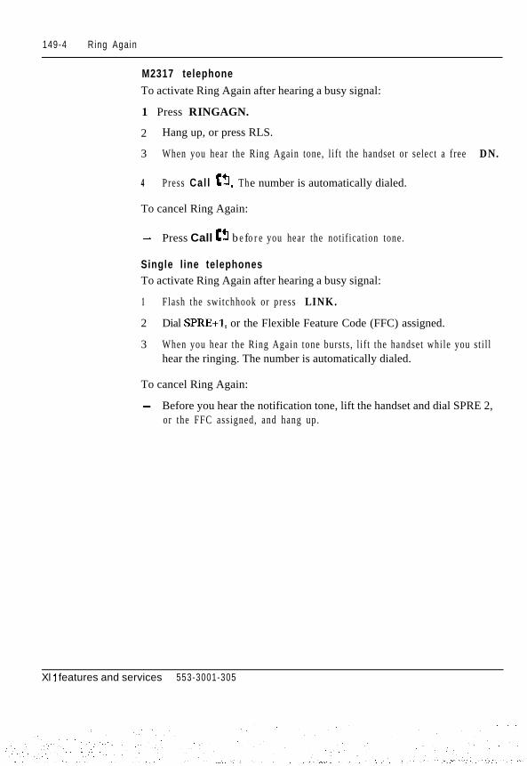
149-4 Ring Again
M2317 telephoneTo activate Ring Again after hearing a busy signal:
1 Press RINGAGN.
2 Hang up, or press RLS.
3 When you hear the Ring Again tone, l if t the handset or select a free DN.
4 Press Cal l CT. The number is automatically dialed.
To cancel Ring Again:
- Press Call e3 b e fo r e you hear the notif ication tone.
Single line telephonesTo activate Ring Again after hearing a busy signal:
1 Flash the switchhook or press LINK.
2 Dial SPRE+l, or the Flexible Feature Code (FFC) assigned.
3 When you hear the Ring Again tone bursts , l i f t the handset while you st i l lhear the ringing. The number is automatically dialed.
To cancel Ring Again:
- Before you hear the notification tone, lift the handset and dial SPRE 2,or the FFC assigned, and hang up.
Xl 1 features and services 553-3001-305

Issued: 93 08 01Status: StandardXl 1 Release: Al l
150-l
Room StatusRoom Sta tus allows customers equipped with a Background Terminal (BGD)to store and retrieve data pertinent to the occupancy, readiness, or cleaningstatus of any guest room or group of guest rooms.
When equipped with the Room Status software, the Meridian 1 systemprovides the following Room Status information:
- Guest registration and occupancy
o c (occupied)V A (vacant)CH (check in)CH OU (check out)
- Cleaning status
RE (cleaning required)PR (cleaning in progress)CL (room cleaned)F A (failed inspection)P A (passed inspection)SK (cleaning skipped)
Xi 1 features and services 553-3001-305
:.:

150-2 Room Sta tus
- Sale status
NS (not for sale)S A (ready for sale)
- Other status information
CCOS (Controlled Class of Service)DND (Do Not Disturb)M W (Message Waiting)CA (Category one - 1 to 15)TL (telephone check)
Do Not Disturb (DND) has been enhanced for interaction with Room Statuson 5OOf2500 telephones. A new customer option al lows a visual indicat ion ofwhen the 500/2500 telephone is in the DND mode: The lamp on the telephonel igh t s up .
The Room Status feature provides four methods of accessing the Room Statusdata:
- Off hook detection: Hotel and hospital staff generally clean occupiedrooms during certain hours of the day. From a Background Terminal(BGD), an option can be entered to set all occupied rooms to “cleaningstatus request” mode for a predefined time-of-day interval. During thisinterval, the Meridian 1 system monitors the room telephone’sswitchhook state to detect a change in the Room Status.
- Dial Access: This method is an enhancement to the off hook detectionmethod for updating the room cleaning status. This method offers sevencleaning-status options, as compared to the two offered by off hookdetection. Again, you al low or deny the dial access method by using theBackground Terminal commands.
Xi 1 features and services 553-3001-305
:: :
: ,., . ,,.

Room Sta tus 150-3
- Room Status key: A Room Status key (RMK) can be provided on anSL-1, M1109, or Meridian Modular Telephone. This allows thetelephone user to read or al ter the status of any room in the system.
- Background Terminal: The Room Status feature is administered from aBackground Terminal (BGD) assigned to the customer. BGDs aredefined in the configuration record and are connected to the Meridian 1system through a serial data interface (SDI) port . Devices used as BGDscan be any ASCII serial terminal conforming to EIA RS-232-C or
CClIT V.24 standards.
Operating parametersThe Room Status key (RMK) is supported only on te lephones equipped witha display.
A room telephone is defined with Controlled Class of Service allowed(CCSA). The fol lowing telephones are supported as room phones:
- 500/2500 telephones
- SL-1 and Ml309 telephones
- Meridian digital telephones
The M3000, M2317, and ACD telephones are not supported as room phones.Room Status is not supported on telephones with DTA (data terminalal lowed) class of service. The RMK is not supported on at tendant consoles.
A room phone is al lowed to change the s tatus of i ts own room.
The Room Status feature is mutually exclusive with the AUTOVON,Multiple-Tenant, Centralized Attendant Service (CAS), and CoordinatedDialing Plan (CDP) features.
A message center must be defined for the Do Not Disturb (DND) visualindication function on 500/2500 telephones. This is mutually exclusive ofIntegrated Messaging System (IMS) and Meridian Mail Message Centers .
All 500/2500 telephones that are to use the Do Not Disturb (DND) visualindication must also have an LPA (Lamp Allowed) Class of Service.
Xi 1 features and services 553-3001-305
,.

150-4 Room Sta tus
Feature interactions- Attendant Administration
Room Sta tus i s not supported by Attendant Adminis t ra t ion.
- Automatic Wake UpRoom Status and Automatic Wake Up both use the BackgroundTerminal (BGD). If the WAKE option is selected for thecheck-in/check-out operation, then the wake-up call for that room iscanceled after a check-in or check-out operation.
- Controlled Class of Service (CCOS)You can change the access restrictions for room telephones from theBGD or from a telephone equipped with a Room Status key (RMK).
- Maid IDMaid ID is not required but is recommended to track maid performance.The Maid ID must be entered each time the Room Status changes, or itwill not be recorded.
- Multiple TenantTelephones equipped with an RMK can change the Controlled Class ofService (CCOS) of telephones for any tenant in a Customer Group.
- Off-Hook Alarm SecurityCleaning changes entered using the Off-Hook Detection Method aremutually exclusive with the Off-Hook Alarm Security feature.
Feature packagingRoom Status (RMS), package 100, requires the following:
- Controlled Class of Service (CCOS), package 81
- Background Terminal (BGD), package 99
For lamp status, the requirements are as follows:
- Do Not Disturb, Individual (DNDI), package 9
- Message Center (MWC), package 46
Xi 1 features and services 553-3001-305

Room Sta tus 150-5
Feature implementationNote: This procedure assumes that a BGD has been assigned. Refer toBackground Terminal Facility description (553-2311-316) for acomplete description and list of commands for the BackgroundTerminal.
LDlO - Add or change Controlled Class of Services (CCOS) for 500/2500 telephones requiringRoom Sta tus updates .
R E Q C H G Change
TYPE 5 0 0 Telephone type
T N l s c u Termina l Number
CLS CCSA, (CCSD) Controlled CLS allowed or denied
LDll -Add or change Room Status key (RMK) for digi t display telephones used for Room Status.
R E Q
TYPE
T N
C L S
KEY
C H G
a a a a
l s c u
A D D
D D S
xx RMK
Change
Te lephone type
aaaa = SLI, 2006,2008,2009,2016,2018,2112,2216,2317,2616,3000
Termina l Number
Automatic digit display enabled
Digit display enabled
Room Status key
Xl 1 features and services 553-3001-305

150-6 Room Sta tus
LD15 - Add or change customer data block to allow (or disallow) visual indication of Do NotDisturb @ND) feature.
Offered on the customer level , this applies only to 500/2500 telephones equipped with a MessageWaiting (MW) lamp.
R E Q
TYPE
C U S T
D N D L
ccos
C H G
C D B
o-99
Yes
(No)
U N R
CUN, CTD, TLD,SRE, FRE, FRI,F R 2
Change
Customer data block
Cus tomer number
Indicator goes on when DND is active
Default; indicator does not go on
Unrestricted call service
With CCOS active, the restrictions entered apply
Feature operationTo read the Room Status by using the RMK (display needed):
1 Without l i f t ing the handset , press Status .
2 Dial the Directory Number (DN) of the room telephone. The DN isdisplayed, followed by a dash and a two-digit code.
The first digit indicates occupancy: zero (0) means vacant, one (1) meansoccupied.
The second digi t indicates Room Status:
1 = RE (cleaning required)2 = PR (cleaning in progress)3 = CL (cleaned)4 = PA (passed inspect ion)5 = FA (failed inspection)6 = SK (cleaning skipped)7 = NS (not for sale)
Xi 1 features and services 553-3001-305

Room Sta tus 150-7
To change the Room Status by using the RMK:
1 Without l i f t ing the handset , press Status .
2 Dial the Directory Number (DN) of the room telephone.
3 Dial the new room status as follows:
1 = RE (cleaning required)2 = PR (cleaning in progress)3 = CL (cleaned)4 = PA (passed inspect ion)5 = FA (failed inspection)6 = SK (cleaning skipped)7 = NS (not for sale)
4 Press Status.
To change the Room Status by using Dial Access (from the room telephone):
1 Lift the handset and dial SPRE 86.
2 Dial the room status as shown below:
1 = RE (cleaning required)2 = PR (cleaning in progress)3 = CL (cleaned)4 = PA (passed inspect ion)5 = FA (failed inspection)6 = SK (cleaning shipped)7 = NS (not for sale)
3 Dial * and the Maid ID followed by #, if required.
4 Hang up or press RLS.
Note: For complete details on the Room Status operation, seeBackground Terminal user guide.
Xi 1 features and services 553-3001-305

150-8 Room Sta tus
Xl 1 features and services 553-3001-305

151-l
Secretarial FilteringSecretarial Filtering is an application of Call Forward All Calls. It allows youto forward all calls to a second telephone. The user at the second telephoneanswers the forwarded calls and can choose to transfer the call back to you.
In the following example, a manager at DN 2222 forwards all calls to asecretary at DN 3333.
A call placed to DN 2222 is forwarded to the secretary at DN 3333. Thesecretary answers the calls decides that the manager should take the call , andtransfers i t back to DN 2222. The secretary can also place calls from DN 3333to DN 2222. In this example the manager receives only the calls originated ortransferred by the secretary.
Figure 151-lSecretarial Filtering example
1 Call to 2644 is 2 Call is answered on 2744 3 2744 answers only callsforwarded to 2743 and transferred to 2643 forwarded from 2644.
It can originate andtransfer calls.
Set A Set BPDN 2643 \ PDN 2743
\SDN 2644 p&b SDN 2744CFAC to 2744 553-5359
Xi 1 features and services 553-3001-305
: I
,._.,. ..1_ .:
151-2 Secretarial Filtering
Operating parametersOnly the Directory Number (DN) designated as the Call Forward number canoriginate or transfer calls to the originally dialed DN.
All Single Appearance DNs on the forwarded telephone are forwarded to thetarget DN.
A Multiple Appearance DN on the forwarded telephone is forwarded only ifit is a prime DN.
A Multiple Appearance DN that is not the prime DN rings at al l appearances,including the forwarded telephone.
Feature interactionsThere are no feature interactions.
Feature packagingSecretarial Filtering is included in basic X11 system software. It is providedwith Call Forward All Calls.
Feature implementationThis feature is enabled when Call Forward All Calls is enabled.
Feature operationSee the feature operation in “Call Forward All Calls” on page 40-l.
Xl 1 features and services 553-3001-305

Issued: 92 12 31Status: StandardXl 1 Release: 12
152-le.-
Short Buzz for digital telephonesWhen a cal l is presented to a digi tal telephone that is offhook, a buzz tone isgiven. The duration of this secondary buzz is shortened from 2 seconds to anaverage of 0.8 seconds, with a minimum length of 0.5 seconds and amaximum length of 1 second.
Operating parametersShort Buzz for digi tal te lephones does not apply to SL- 1 te lephones.
Short Buzz for digital sets does not change the buzz tone given to ACDtelephones on the In-calls key.
Feature interactions- Group Call
The special three-second buzz for Group Call is not affected by thisfeature.
Feature packagingThis capabi l i ty is included in basic Xl 1 system software.
Feature implementationNot applicable.
Feature operationNot applicable.
Xl 1 features and services 553-3001-305

152-2 Short Buzz for digital telephones
Xi 1 features and services 553-3001-305
::

Speed CallSpeed Call allows you to place calls by dialing a one-, two-, or three-digitcode. You can use Speed Call for both internal and external calls. To useSpeed Call , SL- 1 telephones, Meridian digital telephones, and at tendantconsoles may have a Speed Call key/lamp pair.
500/2500 telephones can activate Speed Call by using Special Prefix (SPRE)or Flexible Feature Codes (FFC).
500/2500 telephones, SL-1 telephones, Meridian digital telephones, andattendant consoles can be designated as a Speed Call Controller (SCC) or aSpeed Call User (SCU). SCCs can program the numbers to be stored (SpeedCall codes) and can use the Speed Call l is t . SPUs cannot program Speed Callcodes; they can use only the Speed Cal l l is ts .
Each stored number is assigned a Speed Call code from the Speed Call list.Each list may contain up to 1000 telephone numbers (entries). The maximumnumber of digits of the telephone number that can be stored in each entry isspecified by the customer. Speed Call entries can be 4, 8, 12, 16, 20, 24,28,or 3 1 digits long.
Operating parametersYou can define up to 255 (O-254) Speed Call l is ts per system. X 11 release 13and later software allows up to 8191 (o-8190) Speed Call lists per system, aslong as sufficient memory is available. The new maximum includes allcombined Speed Call, System Speed Call (SSC), and Hot Line lists.
Xl 1 features and services 553-3001-305
., . . .:.,: _ . :

153-2 Speed Cal l
You can have as many Speed Call lists as you have available key/lamp pairson any SL-1 telephone, Meridian digital telephone, or at tendant console. Anynumber of users can be assigned to a l ist . 500/2500 telephones can accessonly one Speed Call l is t . More than one Speed Call Control ler can be assignedto each list, but this is not recommended.
A maximum of 31 digits for the telephone number is allowed per Speed Calllist entry. An asterisk (*), which indicates a pause, and an octothorpe (#),which indicates end-of-dialing, may be programmed as part of the entry.
Speed Call list entries can be defined in LD18 or by Speed Call Controllers.Speed Call Controllers must know the digit length (one, two, or three)required for the Speed Call codes in each list.
Feature interactions- Last Number Redial
A number dialed using Speed Call will become the Last Number Redialnumber on all telephones except the M2317 and M3000.
Feature packagingSpeed Call is part of Extended PBX features (OPTF), package 1, and has nofeature package dependencies.
Feature implementation
LD17 - Set maximum number of Speed Call lists.
R E Q C H G Change
TYPE C F N Conf igura t ion Record
M S C L O - 8 1 9 1 Maximum number of Speed Call lists (quantity)
Xl 1 features and services 553-3001-305
‘.,..’

Speed Cal l 153-3
LD18 - Compute Speed Call list memory size and disk records (Xl 1 release 17).
R E Q
TYPE
N O L S
DNSZ
S I Z E
Use this prompt sequence to determine if there is enough memory and diskrecords for new Speed Call lists. Compare the output with the MEM AVAILand DISK AVAIL values output before the REQ prompt.
C O M P Compute d i sk and memory
SCL Speed Call lists
l -8191 Number of lists to be added
4-(16)-31 Maximum length of DN allowed for Speed Call list
1-l 000 Maximum number of entries in Speed Call list
Xl 1 features and services 553-3001-305

153-4 Speed Call
LD18 - Add or change a Speed Call l is t .
REQ NEW, CHG, OUT
T Y P E SCL
LNSO O - 8 1 9 0
DNSZ 4-(16)-31
Add, change, or remove a Speed Call list
Speed Call data block
Speed Call list number
Maximum number of digits in a list entry (4, 8, 12, 16, 20,24, 28, or 31)
SIZE
WRT
STOR
1-I 000
No, PSI
X X X
YY...YY
Maximum number of entries in the Speed Call list
Data is correct and list may be updated
xxx = list entry number (O-9, 00-99, or 000-999)
yy = digits to be stored against the entry (must be equal toor less than DNSZ)
WRT No, (ves) Data is correct and list may be updated
Note: The prompt WRT follows prompts SIZE and STOR, asking you to confirm the correctness of the datajust entered. If data is correct, enter Yes or <CR>. A response of No after the SIZE prompt causes all dataentered to be ignored. A response of No after the STOR prompt generates a warning message (SCH3213)indicating the data was not stored and must be reentered.
A response of - aborts the program. Only the last STOR value is lost. All previous values to which WRTwas Yes are saved.
I n X l 1 r e l e a s e . 1 7 a n d l a t e r , t h e f o l l o w i n g i n f o r m a t i o n i s o u t p u t w i t h t h e WRT p r o m p t , f o l l o w i n g S I Z E :
ADDS: MEM: xxxxx DISK: yy.y
where xxxxx is the amount of protected memory and yy.y is the number of disk records required for the newS p e e d C a l l l i s t . C h e c k t h e M E M A V A I L a n d D I S K R E C A V A I L v a l u e s o u t p u t b e f o r e t h e R E Q p r o m p t .
LDlO - Add or change Speed Call for 500/2500 telephones.
REQ
TYPE
T N
F T R
CHG
500
l s c u
scu Y Y Y Y
see Y Y Y Y
Change
Telephone type
Terminal Number
Speed Call User, list number (O-81 90)
Speed Call Controller, list number (O-81 90)
Xi 1 features and services 553-3001-305

Speed Call 153-5
LDll -Assign a Speed Call list to SL-1 and digital telephones.
R E Q
TYPE
T N
KEY
C H G
aaaa
l s c u
xx scu YYYY
xx see YYYY
Change
Te lephone type
aaaa = SLl ,2006,2008,2009,2016,2018,2112,2216,2317,2616,3000
Termina l Number
System Speed Call User key
Speed Call Controller key
xx = key number
yyyy = Speed Call list number (O-81 90)
Note: M3000 must use key 21. M2317 must use key O-10 or key21.
LD12 -Assign a Speed Call l is t to an at tendant console.
REQ C H G Change
TYPE ATT, 1250,225O Conso le t ype
T N l s c u Termina l Number
KEY xx see YYYY Speed Cal l Cont ro l le r
xx = key number
yyyy = list number (O-81 90)
Xi 1 features and services 553-3001-305

153-6 Speed Cal l
Feature operationTo store Speed Call entries from an SL-1, Meridian digital telephone, orattendant console (Controller):
1 Without l i f t ing the handset , press Speed Call. The indicator f lashes.
2 Dial the Speed Call code (O-999), followed by the phone number itrepresents.
3 Press Speed Call. If the entry is accepted, the indicator goes off. If theentry is not accepted, the indicator continues f lashing.
To make a Speed Call from an SL-1, Meridian digital telephone, or attendantconsole (User):
1 Lift the handset and press Speed Call (telephone).
. Select an idle loop key and press Speed Call (attendant console).
2 Dial the Speed Call code. The telephone number represented by theSpeed Call code is dialed automatically.
To store Speed Call entries from a 500/2500 telephone (Controller):
1 Lift the handset and press octothorpe (#) +2 (2500 telephone) orSPRE+75 (500/2500 telephone).
2 Dial the Speed Call code (O-999), followed by the phone number itrepresents. If the entry is accepted, you hear silence. If the entry is notaccepted, you hear a fast busy tone.
3 Hang up.
Repeat steps one through three for each entry to be stored.
To make a Speed Call (User):
1 Lift the handset and dial #3 (2500 telephone), or SPRE 76 (500/2500telephone).
2 Dial the Speed Call code (O-999). The telephone number represented bythe Speed Call code is dialed automatically.
Note: In addition to SPRE codes your system may be equipped withFlexible Feature Codes (FFCs).
Xl 1 features and services 553-3001-305
: e

Issued: 92 12 31Status: StandardXl 1 Release: 1 3
154- l
Speed CaWAutodial with AuthorizationCodes
This feature is an enhancement to the existing Speed Call and Autodialfeatures. I t al lows a Speed Call entry to contain an authorization code with anassociated trunk route or ESN access code and dialed number. The digitsstored are recorded in CDR, if equipped, for billing purposes.
The Speed Call entry can be one of the following:
- SPRE + 6 + Authorization Code
- SPRE + 6 + Authorization Code + #
- SPRE + 6 + Authorization Code + # + ESN access code and dialednumber
Operating parametersAuthorizat ion Code Condi t ional ly Last i s not supported.
An octothorpe (#) is required as a delimiter after the Authorization Code if anESN access code and dialed number are stored as part of the Speed Call orAutodial key. If the octothorpe is not entered, the user receives a fast busytone. The octothorpe is not s tored in the CDR record.
If the system initializes before the Authorization Code is recorded by CDR,the record may be lost .
An SL- 1 digi ta l d isplay set can display up to 16 digi ts . Addi t ional d igi ts causethe digi ts to scrol l off the display.
Xl 1 features and services 553-3001-305

154-2 Speed CalVAutodial w i th Author iza t ion Codes
The M3000 set can display up to 29 digi ts . Addi t ional digi ts cause the digi tsto scroll off the display. Only one softkey, key 21, can be programmed forSpeed Call.
An M2317 set can display up to 31 digits.
For SL-1 and Meridian digital sets, up to 31 digits per Speed Call entry areallowed.
On digit display sets, Authorization Codes cannot be blocked from beingdisplayed.
There is no validation of the Authorization Code until the Speed Call key isactivated.
Feature interactionsThere are no feature interactions.
Feature packagingThe following packages are required to implement this enhancement:
- Basic Authorization Code (packages 24 and 25) or NetworkAuthorization Code (option 63)
- AutodiaWpeed Call (package 1) or System Speed Call (option 34) orNetwork Speed Call (package 39)
Feature implementationAn Authorization Code can now be entered as part of a Speed Call list.
Feature operationNot applicable.
Xi 1 features and services 553-3001-305
.. .. .) .:
.I.. .

Issued: 9 3 08 01 1S ta tus : StandardXl 1 Release: 19
155-l
Speed Call, SystemSystem Speed Call extends the capabilities of Speed Call. In addition toabbreviated dialing, System Speed Call allows a user to temporarily overridethe telephone’s Class of Service, TGAR access restrictions and coderest r ic t ions .
500/2500 telephones, SLl telephones, Meridian digital telephones andattendant consoles can act ivate System Speed Cal l by using SPRE or FlexibleFeature Codes (FFC).
A 500/2500 telephone can be designated as a System Speed Call User only(not Controller) and can access one System Speed Call list. SL-1 andMeridian digital telephones can be System Speed Call Users (SPRE codes orkey access) or Controllers (key access only). Attendant consoles can beSystem Speed Call Users (dial access only) and System Speed CallControllers (key access only).
Operating parametersPrior to Xl 1 release 13 you can define up to 255 (O-254) System Speed Calllists and regular Speed Call lists can be defined per system. X 11 release 13and later software al lows up to 8 19 1 (O-8 190) Speed Call l is ts , as long assufficient memory is available. The new maximum includes all combinedSpeed Call, System Speed Call and Hot Line lists, 4096 (o-4095) of whichcan be System Speed Call lists.
System Speed Call l is ts may have up to 1000 entr ies and each entry can be upto 3 1 digits in length.
Restrictions applied to a telephone are ignored only for the origination of acall made through System Speed Call. Restrictions are applied if any callmodification is attempted once the call is established.
Xl 1 features and services 553-3001-305
I
,.,..- .‘... ,
155-2 Speed Ca l l , Sys tem
System Speed Call lists can only be programmed in LD18 or from telephonesor attendant consoles equipped with a System Speed Call Controller key.
Prior to X11 release 19, the craftsperson enters each System or regular SpeedCall List individually. X11 release 19 enhances LD 18 so the craftsperson canadd or copy up to 100 System and regular Speed Call Lists at a time.
Feature interactions- Basic or Network Alternate Route Selection (BARVNARS)
If the BARS or NARS package is equipped, an NCOS is assigned to theSystem Speed Call list. The NCOS associated with the System SpeedCall list replaces the NCOS of the telephone if it increases the FacilityRestriction Level (FRL) of the user.
- Authorization CodeIf the Basic Authorization Code (BAUT) or Network AuthorizationCode (NAUT) package is equipped, a Network Class of Service (NCOS)is ass igned to the System Speed Cal l l i s t . The NCOS of the System SpeedCall list replaces the NCOS of the Authorization code or Forced ChargeAccount code if it increases the Facility Restriction Level (FRL) of thecode.
- Attendant AdministrationSystem Speed Cal l l i s ts may be ass igned using AttendantAdministration.
- Last Number RedialA number dialed using a System Speed Call key becomes the LastNumber Redial number on all telephones except the M2317 and M3000.A number dialed using SPRE activated System Speed Call becomes theLast Number Redial number on all telephones. The originalclass-of-service and NCOS restrictions of the telephone apply whenusing Last Number Redial.
- Flexible Feature Code (FFC)With FFC, a confirmation tone is provided for speedcall store after theEOD (end-of-dial) string is entered.
Feature packagingSystem Speed Call (SSC), package 34, has no feature package dependencies.
Xl 1 features and services 553-3001-305
..:
:.::

Feature implementation
Speed Call, System 155-3
LD17 - Set maximum number of Speed Call lists.
R E Q C H G Change
TYPE C F N Conf igura t ion Record
M S C L O-8190 Maximum number of Speed Call lists (quantity)
LD18 - Compute Speed Call list memory size and disk records (Xl 1 release 17).
Use this prompt sequence to determine if there is enough memory and diskspace for new speed call lists. Compare the output with the “MEM AVAIL”and “DISK AVAIL” values output before the REQ prompt.
REQ COMP Compute d i sk and memory
TYPE S C L Speed Call lists
N O L S l-81 90 Number of lists to be added
DNSZ 4-31 Maximum length of DN allowed for Speed Call list
S I Z E l-l 000 Maximum number of entries in Speed Call list
Xl 1 features and services 553-3001-305

155-4 Speed Ca l l , Sys tem
LDIS-Add or change a System Speed Call list.
REQ N E W , C H G , O U T Add, change, or remove a single speed call list;NEW xx, CPY xx Add or copy xx lists
TYPE s s c Sys tem Speed Ca l lS C L Speed Call List
L S N O O-81 90 number of list to add;~XB YYYY xxxx = number of list to be copied;
yyyy = number of list to receive copy
N C O S o-99
DNSZ 4-(16)~31
NCOS to be assigned to calls accessing the list
Maximum number of digits in a list entry (4, 8, 12, 16, 20,24, 28, or 31)
S I Z E
WRT
STOR
l-1 000
No, (Yes)
xxx
YY...YY
Maximum number of entries in the Speed Call list
Data is correct and list may be updated
xxx = list entry number (O-9, O-99, or O-999)
yy = digits to be stored against the entry (must be equal toor less than DNSZ)
W R T No, (Yes) Data is correct and list may be updated
Note: The prompt WRT follows prompts SIZE and STOR asking you to confirm the correctness of the datajust entered. If data is correct, enter “Yes” or <CR>. A response of “No” after the SIZE prompt causes alldata entered to be ignored. A response of “No” after the STOR prompt generates a warning message(SCH3213) indicating the data was not stored and must be reentered.
A response of I-” aborts the program. Only the last STOR value is lost. All previous values to which WRTwas “Yes” are saved.
I n X l 1 r e l e a s e 1 7 a n d l a t e r , t h e f o l l o w i n g i n f o r m a t i o n i s o u t p u t w i t h t h e W R T p r o m p t , f o l l o w i n g S I Z E :
ADDS: MEM: xxxxx DISK: yy.y
Where xxxxx is the amount of protected memory and yy.y is the number of disk records required for the newspeed call list. Check the “MEM AVAIC’ and “DISK REC AVAIc’values output before the REQ prompt.
Xl 1 features and services 553-3001-305

Speed Call, System 155-5
LDlO - Add or change System Speed Call for 500/2500 telephones.
REQ C H G C h a n g e
TYPE 5 0 0 Telephone type
T N l s c u Termina l Number
F T R ssu YYYY System Speed Call user, list number (o-4095)
LDll -Add or change System Speed Call list for SL-1 and digital telephones.
R E Q
TYPE
T N
s s u
KEY
C H G
aaaa
l s c u
YYYY
xx ssu YYYY
xx ssc YYYY
Change
Te lephone type
aaaa = SLl , 2006, 2008, 2009, 2016, 2018, 2112, 2216,2317,2616,3000
Termina l Number
System Speed Call list number (o-4095) for dial access
System Speed Call user key
System Speed Call Controller key
xx = key number
yyyy = System Speed Call list number (o-4095)Note: M2317 and M3000 must use key 21.
LD12 - Add or change a System Speed Call l is t for at tendant consoles.
REQ C H G Change
TYPE ATT, 1250,225O Conso le t ype
T N l s c u Termina l Number
s s u YYYY System Speed Call list number (o-4095) for dial access
KEY xx ssc YYYY System Speed Call Controller key
xx = key number
yyyy = System Speed Call list number (o-4095)
Xl 1 features and services 553-3001-305
.--.:. - - , . . . .
155-6 Speed Call, System
Feature operationTo store System Speed Call entries from an SL-1, Meridian digital telephone,or attendant console (Controller):
1 Without lifting the handset, press Speed Call. The indicator flashes,
2 Dial the Speed Call code (O-999), followed by the phone number itrepresents.
3 Press Speed Call. lf the entry is accepted, the indicator goes off. If theentry is not accepted, the indicator remains f lashing.
To make a System Speed Call from an SL-1, Meridian digital telephone, orattendant console (User):
1 Lift the handset and dial SPRE 73 or press the System Speed Call key(telephone),
-or-
Select an idle loop key and dial SPRE 73 (attendant console).
2 Dial the Speed Call code.
If the Speed Call number is accepted, the telephone number representedby the Speed Call code is dialed automatically. No confirmation tone isgiven unless FFC is implemented.
If the Speed Call number is not accepted, a fast busy signal indicates thenumber was rejected.
To make a System Speed Call from a 500/2500 telephone (User):
1 Lift the handset and dial SPRE 73.
2 Dial the Speed Call code (O-999). The telephone number represented bythe Speed Call code is dialed automatically.
Note: In addi t ion to SPRE codes your system may be equipped FlexibleFeature Codes.
The routine to add a call list aborts under the following conditions:
- trying to add a call list whose number is already in use
- trying to add multiple call lists when there is insufficient memory
Xl 1 features and services 553-3001-305
,
.’ ::.._ .I ,:, ,:.. .‘. : ,.,
~. -.

156-l
Issued: 92 12 31Status: StandardXl 1 Release: 1 7
Station Category IndicationThe Station Category Indication (SCI) feature allows an attendant toselectively answer internal attendant Directory Number (DN) calls on apriori ty basis . Stat ions are assigned a category, with priori ty indicated by anIncoming Call Indicator (ICI) lamp at each attendant console. Using theanswering priori ty defined in LD 1.5, the a t tendant g ives prompt a t tent ion to acall presented at a high-priori ty ICI lamp by selecting the associated ICI key.
Operating parametersA maximum of 7 station categories (l-7) may be assigned.
Calls from SC1 0 stations appear on the dial 0 ICI.
Calls from fully restricted stations appear on the dial 0 fully restricted ICI.
The Station Category Indication (SCI) feature should not be mixed with anyother Incoming Call Indicator (ICI) assignment on the same ICI key/lamppair.
Feature interactions- Controlled Class of Service (CCOS)
The CCOS feature has priority over SCI. A station’s SC1 category issuppressed when CCOS is active, and calls to the at tendant DN carry theCCOS class defined in the database.
- Centralized Attendant Service (CAS)When CAS is active, calls from a remote station to the attendant DNappear on the remote ICI key/lamp pair at the CAS main, regardless ofthe s ta t ion SC1 category.
Xl 1 features and services 553-3001-305

156-2 Station Category Indication
Feature packagingStation Category Indication (SCI), package 80, has no feature packagedependencies.
Feature implementation
LD15 - Add or change a Stat ion Category Indication ICI key/lamp pair for at tendant consoles.
R E Q
TYPE
C U S T
ICI
ICI
ICI
C H G
C D B
o-99
O-l 9 CA1 -CA7
O-1 9 DLO
O-1 9 DFO
Change
Customer data block
Cus tomer number
Assign ICI key/lamp pair for SCI
Dial 0 (calls from telephones in SCI 0)
Full restricted (call from fully restricted telephones)
LDlO- Change SC1 for 500/2500 telephones.
R E Q
TYPE
T N
SCI
C H G
5 0 0
l s c u
o-7
Change
Te lephone type
Termina l Number
SCI number
LDll- Change SC1 for SL-1 and Meridian digital telephones.
R E Q
TYPE
T N
SCI
C H G
aaaa
l s c u
o-7
Feature OperationNot applicable.
Change
Te lephone type
aaaa = SLI ,2006,2008,2009,2016,2018,2112,22~ 6,2317, 2616, 3000
Termina l Number
SCI number
Xl 1 features and services 553-3001-305

Issued; 93 08 01Sta tus : Standard
Xl 1 Release: 1 9
157-l
Station Specific Authorization CodeStation Specific Authorization Code (SSAU) is available with Xl 1 release 19and later, and enables the system administrator to control the level ofauthorization code access on a per telephone basis. SSAU applies to 500/2500and digi ta l te lephones; i t does not apply to BRI te lephones.
Station Specific Authorization Code provides three levels of authorizationcode access:
1 AUThcode Unrestricted (AUTU)An AUTU telephone has no authorization code access l imitat ions. Anyauthorization code is accepted and processed normally.
2 AUThcode Restricted (AUTR)An AUTR telephone can enter up to six assigned authorizat ion codes.The authorization code entered must match one of the pre-assignedcodes. Any other authorization code will be rejected and the call wil l notbe completed.
3 AUThcode Denied (AUTD)An AUTD telephone has no access to authorization codes. Anyauthorization code will be rejected and the call will not be completed.
Xl 1 features and services 553-3001-305

157-2 Sta t ion Spec i f i c Au thor iza t ion Code
Operating parametersThe same authorization code may be assigned to more than one AUTRtelephone.
There is cross-checking between Overlays 10 and 11, which define a stationspecific authorization code, and Overlay 88, which ensures that the user hasentered a valid authorization code.
Overlay 88, which is used to delete an existing authorization code, does notcheck if the authorization code is assigned as a stat ion specific authorizationcode before the deletion.
The Station Specific Authorization Code feature does not apply when theauthorization code is prompted from a tandem node.
Feature interactions- Attendant Administration
Stat ion Specif ic Authorizat ion Code does not support AttendantAdministration.
- Authorization CodeUsers cannot freely enter authorization codes from telephones that have
AUTR or AUTD class of service.
- AutodialThe SSAU feature treats stored autodial numbers as if they were enteredat the telephone.
- Speed CallThe SSAU feature treats stored speed call numbers as if they wereentered at the telephone.
Feature packagingStation Specific Authorization Code (SSAU) is available as package 229.Basic Authorization Codes (BAUT) (package 25) is a prerequisite.
Xl 1 features and services 553-3001-305
....... : ......... ......

Station Specific Authorization Code 157-3
Feature implementationThe following entries create the Authorization Code data block:
LDSS - Create Authorization Code data block (AUB).
Prompt Response
REQ NEW
TYPE A U B
CUST o-99
S P W D xxxx
ALEN 1-14
A C D R YES, NO
R A N R o-51 1
CLAS (0)-l 15
c o s a a a
TGAR (O)-31
N C O S ON@
A U T O YES, NO
-SECR o-9999
-NMBR l-9999
-cLAs (0)-l 15
Comment
C r e a t e
Authcode da ta b lock
Cus tomer number
Secure da ta password
Number of digits in authcodes
Activate CDR for authcodes
RAN route number for “AuthcodeLast” prompt (NAUT)
Class code value assigned toau thcode (NAUT)
Class of Service
Trunk Group Access Restrictions
Network Class of Service
Automat ica l l y genera te au thcodes
Security password (NAUT)
Number of authcodes to begenerated
Class code value assigned toau thcode (NAUT)
Xi 1 features and services 553-3001-305
.,

157-4 Sta t ion Spec i f i c Au thor iza t ion Code
The following entries create the Authorization Code Table.
LDSS - Create an Authorization Code Table.
Prompt Response
R E Q N E W /
TYPE AUT
C U S T o-99
S P W D XXXX
C O D E xxxx
CLAS (0)-l 15
Comment
C r e a t e
Author iza t ion Code Tab le
Cus tomer numbers
Secure data password
Authcode (number of digits mustequal ALEN)
Class code value assigned toau thcode (NAUT)
Xl 1 features and services 553-3001-305
.‘..,

Station Specific Authorization Code 157-5
The following service changes are required to activate Station SpecificAuthorizat ion Code.
LDlO/ll - Activate SSAU.
Prompt Response
R E Q NEW/CHG
TYPE xxxx
Comment
Add or modify
Te lephone type:500 (500 or 2500)2006,2008,2009,2016,2018,2112, 2216, 2317, 2616,3000,SLI
C L S
MAUT
PJW,A U T R ,A U T D
YES/(NO)
Authcode unres t r i c tedAuthcode res t r i c tedAuthcode den ied
Modify assigned authcodes forth is te lephone
S P W D xxxx Correct security password (if oneis defined)
A U T H x nnnn x is in the range of l-6; nnnn is theassigned authcode (a validauthorization code defined inOverlay 88).
x x X x deletes an assigned authcode.
Note: Changing an AUTR telephone to AUTU or AUTD clears all assignedauthcode information previously defined for that telephone.
Feature operationAfter an authorization code is entered, the Station Specific AuthorizationCode feature determines if the set is allowed to use the entered code. If theauthorization code is not allowed on that set, the existing invalidauthorization code treatment occurs. Otherwise, normal authorization codeprocessing occurs.
Xl 1 features and serv ices 553-3001-305
_:,. ,. . . . , : ..,. ,,:’ .: .‘.. ,, : .:. -,.. .::.

157-6 Station Specific Authorization Code

Issued: 92 12 31Status: StandardXl 1 Release: Al l
158-l
Station-to-Station CallingStation-to-Station Calling allows direct dialing between station users in thesame customer group without the assistance of the at tendant .
Operating parametersThere are no feature requirements.
Feature interactions- Manual Line Service
If a single line telephone has been assigned a Manual Line Class ofService, the telephone automatically r ings the at tendant when i t goesoffhook.
- Private LinesYou must go over the public network to reach a Private Line. Thesoftware PRDN is not meant to be dialed directly.
Feature packagingStation-to-Station Calling is included in basic Xl 1 system software.
Feature implementationNot applicable.
Feature operationThere is no specific procedure required to operate this feature.
Xl 1 features and services 553-3001-305
,
: .

158-2 Sta t ion- to -Sta t ion Ca l l ing
Xi 1 features and services 553-3001-305
,
-.:- : : .f . ,__,.,; -, ‘. .‘:-‘_
-.. . . . . _.‘. ‘,‘.‘.,.) ‘..,,,,,__,_, _,.,, ,i :I,‘:’ ‘:. : ,\,
/,

Stored Number RedialStored Number Redial (SNR) allows telephones and attendant consoles tostore one previously dialed number of 4 to 3 1 digits for automatic redialing.
Depending on the type of telephone, the number can be stored before a call isplaced, during Ringback, while the number is busy, or during an active call.On attendant consoles, the number can be stored only before a call is placed.Stored Number Redial (SNR) is not supported on M23 17 telephones, M3000Touchphones, or 5OOl2500 telephones serving as Private Lines.
Operating parametersWhen a number is stored, i t overwrites any previously stored number.
Storage is l imited to one number per s ingle l ine telephone and one number perSNR key. When a call is established through a Tandem Tie Trunk Network(TTTN), the user is required to pause for dial tone. When you store a numberusing SNR, automatic redialing may fail because required delays are notadded. I t is possible to include delays in the outpuls ing by dial ing the aster isk(*) in the original digit string where dial tone is expected. Each asterisk (*)signif ies a 3 second delay in outpuls ing.
The 3 second delay is not available from a 500-type telephone.
During the stored Number Redial (SNR) programming mode, if the userattempts to store more digits than the maximum number defined for thetelephone or console, SNR programming is canceled and overflow tone isreturned. During an active call on an SL-1 or digital telephone, if a userat tempts to s tore more digi ts than the specif ied l imit , the SNR operat ion fai ls ,the previously stored number remains unchanged, and a failure indication isnot given. The SNR indicator remains off.
Xl 1 features and services 553-3001-305

159-2 Stored Number Red ia l
For 500/2500 telephones, in order to store a number dialed to a busy DN, themaximum length of the stored number must be at least 5 (seeprompt FTRRDL xx in LDlO).
Feature interactions- Authorization Code, Charge Account, Forced Charge Account
The Authorization, Charge Account, and Forced Charge Account codesare not stored. To store a code, dial the code prior to using StoredNumber Redial to dial the call.
- End-to-End Signaling (EES)EES activates after a call to a trunk is established by expiration of theend-of-dial t imer. Further digits dialed are not stored by the SNR featureonce it is in EES mode.
Feature packagingStored Number Redial (SNR), package 64, has no feature packagedependencies.
Xl 1 features and services 553-3001-305

Stored Number Redial 159-3
Feature implementation
LDlO - Add or change SNR for s ingle l ine telephones.
R E Q
TYPE
T N
CLS
F T R
C H G
500
lscu
XFA, (XFD)
RDL xx
Change
Te lephone type
Termina l Number
Call Transfer allowed
Activate SNR
xx is the maximum number of digits that can be stored
xx = 4, 8, 12, (16), 20, 24, 28, 31
LDll -Add or change SNR for SL-1 and Meridian digital telephones.
R E Q C H G
TYPE aaaa
T N l s c u
KEY xx RDL yy
Change
Te lephone type
aaaa = SLl , 2006,2008, 2009, 2016,2018,2112,2216,2317, 2616,300O
Termina l Number
Add an SNR key
xx = key number
yy is the maximum number of digits that can be stored
yy = 4, 8, 12, (16), 20, 24, 28, 31
LD12 - Add or change SNR for at tendant consoles.
R E Q
TYPE
T N
KEY
C H G
ATT, 1250,225O
l s c u
xx RDL
Change
Conso le t ype
Termina l Number
Add a SNR key
Xi 1 features and services 553-3001-305

159-4 Stored Number Red ia l
Feature operationAttendant consoles, SL-1, and digital telephones
To store a number prior to dialing (for attendant consoles, SL-1, and digitaltelephones):
1 Without lifting the handset, press Stored No.
2 Dial the number.
3 Press Stored No. again. The number is stored, replacing any previousone.
To store a number during Ringback, while the number is busy, or during anactive call (for SL-1 and digital telephones only):
1 Press Stored No.
To call a stored number:
1 Press DN (SL-1 or digital telephones) or the Loop key (consoles).
2 Press Stored No. The number is dialed.
500/2500 telephonesTo store a number prior to dialing:
1 Lift the handset .
2 Dial SPRE 78, or the FFC assigned for SNR.
3 Dial the number to be stored.
4 Hang up. The number is stored, replacing any previous one.
To store a number before a call is placed, during Ringback, while the numberis busy, or during an active call:
1 Flash the switchhook or press LINK.
2 Dial SPRE 78, or the FFC assigned for SNR.
To call a stored number:
1 Lift the handset .
2 Dial SPRE 79, or the FFC assigned for SNR. The number is dialed.
Xi 1 features and services 553-3001-305

Issued: 93 08 01Status: StandardXl 1 Release: Al l
160-I
TelephonesThere are several different types of telephones you can use in the Meridian 1system. Regular telephones are compatible with the Meridian 1 system, aswell as several special business telephones designed specifically to takeadvantage of the many features available.
This module provides an overview of the telephones and a description of thebasic features and services. Additional information regarding relatedsoftware features is found in other modules of this document.
Note: “Digital telephones” is used as a generic term and includes theM2000 series telephones, the M23 17 telephone, the M3000 Touchphone,and Meridian Modular Telephones.
500/2500 type telephones500/2500 type telephones are regular telephones not normally associated witha business environment, but they are compatible with the Meridian 1 system.The 500 type telephones have a rotary dial . The 2500 type telephones are thebasic push-button models , such as the Link and Unity, which do not havefeature but tons normally found on business telephones.
Xl 1 features and services 553-3001-305
,

160-2 Telephones
Although 500/2500 type telephones do not have feature keys, you can accessvarious system features using Special Prefix (SPRE) codes. SPRE codes arealso useful for SL-1 or Meridian digital telephones to access features withoutusing feature keys. Dial the SPRE code (unique to each customer within thesystem) and then the feature code that applies to the operation you desire.Table 160-l lists the feature codes available using SPRE.
Table 160-lFeature codes used with SPRE (Part 1 of 2)
Dial SPRE + Operation performed
1 Ring Again
2 Cance l R ing Aga in
3 Ringing Number, Call Pickup
4 TAFAS (Trunk Answer From AnySta t ion)
5 Charge Account for CDR
6 Author i za t ion Code Access
70 + ACOD + mmm (Trunk Route Trunk Verification From StationAccess Code and Member )
71 + DN Call Park, To Park
72+DN Call Park, To Retrieve
7 3 System Speed Call, To Use
7 4 Call Forward activate or cancel(500 type te lephones)
75 + Entry Access Code + DN(500 type telephones)
76 + Entry Access Code(500 type telephones)
7 7
7 8
7 9
8 1
8 3
8 4
Speed Call, Individual To ProgramEntry
Speed Call, Individual To Use Entry
Permanent Ho ld(500 type telephones)
Stored Number Redial, To Store
Stored Number Redial, To Redial
Au tomat i c Se t Re loca t ion
Malicious Call Trace
In teg ra ted Messag ing Sys tem
Xl 1 features and services 553-3001-305
,.:
.,, .‘, ,. ._. : .;;: -.i’

Telephones 160-3
Table 160-lFeature codes used with SPRE (Part 2 of 2)
Dial SPRE +
86 + x (status)
86 + 1
86 + 2
86 + 3
86 + 4
86 + 5
86 + 6
86 + 7
8 7
8 9
9 1
9 2
9 3
9 4
9 5
9 6
9 7
9 8
Operation performed
Room Sta tus
Clean ing Reques t
C lean ing In Progress
Room Cleaned
Passed Inspec t ion
Failed Inspection
Cleaning Sk ipped
Not For Sale
Disconnect Trunk,Conference 6 (500/2500 te lephones)
Las t Number Redial
Access to maintenance programs byMain tenance Te lephone
Terminal Diagnostics, telephones andat tendant conso les
Conference Circuit Testing
Ring ing Number , Group P ickup
Ringing Number, DN Pickup
Centrex Sw i t chhook F lash
Unass igned ACD-PBX te lephoneLog in/out
Unass igned ACD-PBX te lephoneActivate/deactivate Not Ready
Xl 1 features and services 553-3001-305

160-4 Telephones
Table 160-22500 type telephone features (No SPRE code used)
#+I +DN Call Forward
# + 2 + Speed Call code + DN Speed Call, Individual, To ProgramEntry
;. # t 2 t Speed Call code t * Speed Call, Individual, To EraseEntry
# + 3 t Speed Call code Speed Call, Individual, To Use Entry
#+4 Permanent Ho ld
SL-1 telephonesThe SL-1 telephone is designed specifically for the Meridian 1 system andallows the user to access many system features. All SL-1 telephones areequipped with a 12-key dial pad, 10 feature keys, and 3 fixed control keys.Table 160-3 summarizes the different models of SL-1 telephones.
Table 160-3SL-1 telephones
Comments
QSU1 No display.
QSU3 Same as QSUI, with a 16-character display window.
QSU6 Same as QSUI, with two headset or handset jacks. Intended forAutomatic Call Distribution (ACD) operations.
QSU7 Same as QSU3, with two headset or handset jacks. Intended forAutomatic Call Distribution (ACD) operations.
QSUGO Similar to QSUl, with minor alterations for the U.S. market.
QSU61 Similar to QSU3, with minor alterations for the U.S. market.
QSU71 The Meridian Ml 109 telephone. Similar to the QSUI, withbuilt-in Handsfree.
Xl 1 features and services 553-3001-305

Telephones 160-5
The SL-1 telephone is designed to accommodate various add-on modules toincrease i ts functionali ty. Table 160-4 l is ts the modules you can add on to anSL-1 telephone.
Table 160-4Add-on modules available for SL-1 telephones
Add-onmodule Description Comments
QMTI 10 key/lamp strip Requi res add i t iona l power
QMT2 20 key/lamp strip Requi res add i t iona l power
QMT3 Lamp Field Array Requi res add i t iona l power
QKKI Handsfree Interface kit Requ i res add i t iona l power
QKK3 Automat i c Hands f ree Requi res add i t iona l powerInterface kit
Q K K 8 Answerback Interface kit QSU71 only
QKNI Headset interface kit
QSAMB Group listening switch Allows caller to be heardth rough se t ’ s loudspeaker
QMTl5 Ampl i f ied Handset Requires Current Limiting Kit(PO630408)
Q K M 1 3 Light Probe Kit For sight-impaired users
Xi 1 features and services 553-3001-305
. ‘., : . : ..,

160-6 Telephones
M2000 series digital telephonesM2000 series digital telephones are available on X11 release 7 and latersoftware. They are designed to provide integrated voice and datacommunication. Use the M2000 Asynchronous Data Option to make datacalls. There are three models in the M2000 series:
- M2009 has 9 programmable keys.
- M2018 has 18 programmable keys.
- M2112 has 11 programmable keys and one fixed Handsfree key.
M2000 series digi tal telephones are not designed for use in an ACDenvironment .
M2317 digital telephoneThe M2317 digital telephone is available on X11 release 9 and later software.It is equipped with a two-line (40 characters per line) liquid crystal display(LCD) screen and integrated Handsfree. To make data calls, you need anM2000 Asynchronous Data Option.
Five soft , or screen dependent, keys are located beneath the display screen.These keys, when operated, activate the function that the screen abovedescribes as being accessible. Each soft key is associated with a label, sevencharacters wide, on the display screen immediately above the key.
Soft keys are designated as key numbers 17 through 29. When the M2317 isconfigured in the system software, certain default features are automaticallyassigned to the soft keys. Some features cannot be added to the soft keys. SeeTable 160-5 for a description of soft key feature assignments.
Note I : Key 11 automatically defaults to Handsfree and cannot beassigned. Keys 12 through 16 and key 18 are reserved for futuredevelopment and cannot be assigned.
Note 2: The second appearance of a data DN must be assigned to key10 on the voice TN, for keypad dialing.
Xi 1 features and services 553-3001-305
,
_. ‘, ~- .-. _ . _. , ,I. ., ,: ..’ : : ‘,i:., :,.

Telephones 160-7
Table 160-5M2317 soft key feature assignments
Key No. Mnemonic Feature
Default feature assignments:
1 1 Han&free/mute
1 7 P R K Call Park
2 3 A06 C o n f e r e n c e 6
2 4 CPN Cal l ing Par ty Number
2 5 C H G Charge Account
2 6 T R N Call Transfer
2 7 R G A Ring Again
2 8 P R S Pr i vacy Re lease
2 9 L N G Language
Keys reserved for specific features (programmed in LDI 1):
1 9 R N P Ring ing Number P ickup
2 0 MWK Message Wa i t i ng
2 1 ssu, ssc Speed Call or System Speed Callscu, see
2 2 C F W Call Forward
Note: Default key assignments are activated only if the feature is part of yoursoftware package, the feature is defined for this customer, and the feature isa l l o w e d f o r t h e t e l e p h o n e .
Xl 1 features and services 553-3001-305
:

160-8 Telephones
M3000TouchphoneThe M3000 Touchphone is available on X11 release 7 and later software. Itis a digi tal , integrated voice/data telephone with a touch sensi t ive l iquidcrystal display (LCD) screen and integrated Handsfree. An M3000Asynchronous Data Option provides data cal l capabil i ty.
All features are displayed on the screen and are accessed by touching theappropriate name on the screen. The M3000 can display a number of onlinefeature descriptions and operating instructions in user-friendly language.
The M3000 has a directory that can store from 150 to 450 numbers (up to 28digits) and names (up to 15 characters) that you can access by simplytouching the screen. You can search the directory or scroll the display up ordown, and dial the desired telephone number by touching the name on thescreen.
The M3000 Touchphone is not designed for use in an ACD environment.
When the M3000 is configured in the system software, certain defaultfeatures are automatically assigned to the telephone. Table 160-6 givesinformation on feature key assignments.
Note: The second appearance of a data DN must be assigned to key 17on the voice TN for keypad dialing.
Xi 1 features and services 553-3001-305
_

Telephones 160-9
Table 160-6M3000 feature key assignments (Part 1 of 2)
Key No. Mnemonic Feature
o - 5 S C R Single Call Ringing
M C R Multiple Call Ringing
D I G Dial Intercom Group
P V R Private Line Ringing
c o s Controlled Class of Service
6-16 Reserved for future development
1 7 S C R Second appearance of data DN (if CLS = DTA)
1 8 S I G Manual S igna l ing (Buzz)
1 9 Reserved for future development
2 0 MWK Message Wa i t i ng
2 1 scu Speed Ca l l Usersee Speed Cal l Cont ro l le rs s u System Speed Call Users s c System Speed Call Controller
2 2 C F W Call Forward All Calls
Xl 1 features and services 553-3001-305
. - . .

160-10 Telephones
Table 160-6M3000 feature key assignments (Part 2 of 2)
Key No. Mnemonic Feature
M3000 Default feature assignments:
2 3 A06 Conference 6
2 4 C W T Call Waiting
2 5 C H G Charge Account
2 6 T R N Call Transfer
2 7 R G A Ring Again
2 8 PRS Pr i vacy Re lease
2 9 Reserved for future development
3 0 M S B Make Set Busy
3 1 P R K Call Park
3 2 CPN Cal l ing Par ty Number
3 3 A R C At tendan t Reca l l
3 4 O V R Overr ide
3 5 AAK Automat i c Answerback
3 6 D S P Disp lay
Features NOT supported by the M3000:
N H C No Ho ld Con fe rence
c s Combined No Ho ld Conference and Speed Ca l l
DPU Directed Call Pickup
G R C Group Cal l
G P U Group Number P ickup
v c c Voice Call
Note 7: Default key assignments are activated only if the feature is part of yours o f t w a r e p a c k a g e , t h e f e a t u r e i s d e f i n e d p e r c u s t o m e r , a n d t h e f e a t u r e i s a l l o w e d i nclass of service.
Xl 1 features and services 553-3001-305

Telephones 160-l 1
Meridian Modular TelephonesThe Meridian Modular Telephones are available with Xl 1 release 14 andlater software. They are designed to provide cost effective integrated voiceand data communication capabil i ty. These telephones communicate with theMeridian SL-1 and SL-100, using digital transmission over standardtwisted-pair wiring. Table 160-7 summarizes the different models ofMeridian Modular Telephones.
Note: When a modular telephone is equipped with either a display ordata option, a PROGRAM key (key 5 for M2006, key 7 for all remainingmodular telephones) is automatical ly assigned to the upper r ight-handfeature key. This feature provides user control over such display featuresas screen format, contrast , and language. It also provides user controlover such parameters as transmission speed, parity, and terminal mode.
Table 160-7Meridian ModularTelephones
Set type Programmablekeys Additional comments
M2006 6 Sing le- l ine on ly
M2008 8 Mul t i - l ine
M2616 1 6 Programmable Handsf ree
M2016S 1 6 Te lephone Secur i ty GroupClass II approved
M221 GACD-1 1 6 ACD Display module and twoRJ-32 headset jacks
M2216ACD-2 1 6 ACD Display module; one RJ-32 andone PJ-327 headset jacks
Xl 1 features and services 553-3001-305
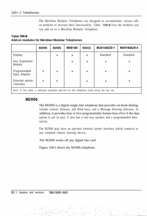
160-l 2 Telephones
The Meridian Modular Telephones are designed to accommodate various addon modules to increase their functionali ty. Table 160-8 l i s t s the modules youcan add on to a Meridian Modular Telephone.
Table 160-6Add-on modules for Meridian Modular Telephones
M2006 M2006 M2016S M2616 M2216ACW1 M2216ACD-2
Disp lay X X X Standard Standard
Key Expans ion X X X X
Module
Programmable X X X X X X
Data Adapter
Externa l a le r te r X X X X X
i n t e r f ace
N o t e : I n t h i s t a b l e , x i n d i c a t e s a v a i l a b l e a d d - o n s f o r t h e t e l e p h o n e l i s t e d a l o n g t h e t o p r o w .
M2006The M2006 is a digital single-line telephone that provides on-hook dialing,volume control, Release, and Hold keys, and a Message Waiting indicator. Inaddition, it provides four or five programmable feature keys (five if the dataoption is not in use). I t also has a one-way speaker and a programmable dataop t ion .
The M2006 may have an optional external alerter interface which connects toany standard remote alerting device.
The M2006 works off any digital line card
Figure 160-l shows the M2006 telephone.
Xl 1 features and services 553-3001-305

Telephones 160-l 3
Figure 160-lM2006 telephone
r
Switchook
Brandline insert
.Speaker
000000000000<<< >>> 1
’ 1 V o l u m ec o n t r o l
553-l 850
Xi 1 features and services 553-3001-305

160-14 Telephones
M 2 0 0 8The M2008 digital telephone has eight programmable feature/line keys,on-hook dialing, volume control, Release, and Hold keys and a MessageWaiting indicator.
The M2008 also supports the programmable data adapter, alphanumericdisplay, and external alerter interface options.
Figure 160-2 shows the M2008 telephone.
Figure 160-2M2008 telephone
Switchook -
Rls key -
Hold Key -
Volume-control
1
\YIxx
L
\m000000000000<<‘ >>>
Iiller plate
3randline insert
speaker
Message Waitingamp
-unction keysand LCDs
P r i m e D N
X1 1 features and services 553-3001-305

Telephones 160-15
M2616, M2216 (Models 1 and 2)The 2616 telephone has 16 programmable feature/line keys, on-hook dialing,volume control, Release, and Hold keys, Message Waiting indicator, andhandsfreelmute features. I t supports up to tow add-on modules of (each of 22keys), an alphanumeric display option (two lines of 24 characters each),programmable data adapter, and a external alerter interface.
The M2616 Model 1 and the M2216 Model 2 are almost identical to theM2616 with the following exceptions:
- Have no switchhook because they are designed for plug-in handset orheadset operation
- Display is standard rather than optional
Model 1 and Model 2 refer to the types of headsets with which the M2216operates.
Figure 160-3 shows the M2616 telephone.

160-16 Telephones
Figure 160-3M2616 telephone
Rls k e y
H o l d k e y
Filler plate
Brandline insert
Speaker
Message Wait@l a m p
-I 6 F u n c t i o n k e y swith 6 LCDs
-Microphone( 2 6 1 6 )
P r i m e D N
553-I 852
Xl 1 features and services 553-3001-305

Telephones 160-17
Related documentationRefer to the following publications for additional information on telephonesand add-on modules.
- Meridian I te lephones descript ion and speci f icat ions (553-3001-108)
- Digital telephone line engineering (553-2201-180)
- Telephone and at tendant console ins tal la t ion (553-3001-215)
- XII input/output guide (553-3001-400)
Operating parametersRefer to the preceding Northern Telecom publications.
Feature interactionsRefer to the preceding Northern Telecom publications.
Feature packaging500/2500 type and SL-1 telephone capabilities are included in basic Xl 1system software.
Digital Sets (DSET), package 88, has no feature package dependencies(Meridian M2000 series telephones).
M2317 telephone (DLT2), package 91 requires
- Digital Sets (DSET), package 88
M3000 Touchphone (TSET), package 89 requires
- Digital Sets (DSET), package 88
Meridian Modular Telephones (ARIE), package 170 requires
- Digital Sets (DSET), package 88
- M3000 Touchphone (TSET), package 89
Xi 1 features and services 553-3001-305
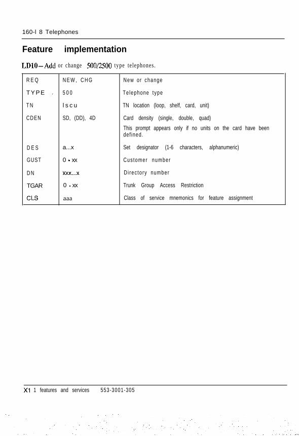
160-l 8 Telephones
Feature implementation
LDlO-Add or change 500/2500 type telephones.
R E Q N E W , C H G New or change
TYPE m. 5 0 0 Te lephone type
T N l s c u TN location (loop, shelf, card, unit)
CDEN SD, (DD), 4D Card density (single, double, quad)
This prompt appears only if no units on the card have beendef ined.
D E S a...x Set designator (1-6 characters, alphanumeric)
GUST 0 - xx Cus tomer number
D N xXx.,.x Di rec to ry number
TGAR 0 - xx Trunk Group Access Restriction
CLS aaa Class of service mnemonics for feature assignment
Xi 1 features and services 553-3001-305

Telephones 160-I 9
LDll -Add or change SL-1 and digital telephones.
R E Q N E W , C H G
TYPE aaaa
T N
CDEN
l s c u
SD, DD, 4D
New or change
Te lephone type
aaaa = SLI , 2006,2008,2009,2016,2018,2112, 2216,2317,2616,3000
Termina l Number
Card density (single, double, quad). Not prompted for octaldensity.
This prompt appears only if no units on the card have beendef ined.
D E S
CUST
AOM
a...x
0-9s
Ko-2
K L S
TGAR
CLS
KEY
1-7
o-xx
a a a
xx aaa yyy.. . y
Note: Card density must be 4D if TYPE is not SL-1.
Designator (1 - 6 characters, alphanumeric)
Cus tomer number
Number of key expansion modules
Prompted if TYPE = 2016, 2216 or 2616
Number of key/lamp strips (SL-1 telephones only)
Trunk Group Access Restriction
Class of service mnemonics for feature availability
DN and feature key assignment (key number, featuremnemonic, directory number if applicable)
Note 7: A Message Waiting allowed (MWA) Class of Service must be defined to enable the messagew a i t i n g l a m p .
Note 2: Key 7 (key 5 for M2006) is reserved for the PROGRAM key (M2008, M2016S, M2216ACD, M2616)o n l y i f d i s p l a y o r d a t a i s e q u i p p e d .
Xl 1 features and services 553-3001-305

160-20 Telephones
LD17-Meridian Modular Telephones related prompts and responses.
R E Q C H G Change
TYPE C F N Conf igura t ion record
A T R N (No), Yes Change t ransmiss ion parameters
CODE “:’ (O)-2 CODEC cod ing law
S O L R 0-4 Sidetone Ob jec t i ve Loudness Rat ing
ROLR (0)-12, 32-50 Rece ive Ob jec t i ve Loudness Rat ing
TOLR (0)-63 Transmit Objective Loudness Rating
Note: Default settings are recommended. See Summary of transmission parameters(553-2201-l 82) before changing these parameters.
LD17 - Meridian Modular Telephones related prompts and responses for Xl 1 release 18 and later.
R E Q C H G Change
TYPE C F N Conf igura t ion record
A T R N (No), Yes Change t ransmiss ion parameters
C O D E KJ)-2 CODEC cod ing law
S O L R O-(1)-4 Sidetone Ob jec t i ve Loudness Rat ing
ROLR (O)-63 Rece ive Ob jec t i ve Loudness Rat ing
TOLR (O)-63 Transmi t Ob jec t i ve Loudness Ra t ing
A G C D Yes, (No) Automat ic Ga in Cont ro l d isab led
Note: Default settings are recommended. See Summary of transmission parameters (553-2201-182)before changing these parameters.
Xl 1 features and services 553-3001-305
,..

Telephones 160-21
LDll -Add data TN to digital telephones.
R E Q N E W
TYPE aaaa
T N
D E S
CLS
DTYP
A D C P
K E Y
l s c u
a...x
a a a
10s
Yes, (No)
xx aaa yyy...y
N e w
Telephone type
aaaa = 2006,2008,2009,2016,2018,2112,2216, 2317,2616,300O
Termina l Number
Set designator (1 -6 characters alphanumeric)
Class of service mnemonics for feature availability
Inbound/ou tbound da ta s ta t ion
All digital connection prefix
DN and feature key assignment (key number, featuremnemonic, directory number if applicable). See Note.
Note: Recommended key assignments for data TN areKey 0 = DN (for data)Key 1 = DN (secondary)K e y 2 = T R N ( T r a n s f e r )Key 3 = ADL xxxx (Auto Dial directory number)K e y 4 = RGA ( R i n g A g a i n )Key 5 = SSC, SCU, SSC, SSU (Speed Call, System Speed Call, controller or user-
n o t a v a i l a b l e o n M 2 0 0 6 )Key 6 = DSP (Display key for M2008, M2016S, M221 GACD, M2616)
Xl 1 features and services 553-3001-305

160-22 Telephones
LDll -Add data TN to SL-1 telephones with data module.
R E Q N E W N e w
TYPE SLl SL-1 te lephone
T N lscur y. TN location (loop, shelf, card, unit)Unit number equals the voice TN unit number plus 8
CUST 0 - xx
CLS W T D
KEY xx aaa yyy...y
Customer number
Warn ing tone denied
DN and feature key assignment (key number, featuremnemonic, directory number if applicable). See Note.
Note: Recommended key assignments for dataTN areKey 0 = DN (for data)Key 1 = DN (secondary)K e y 2 = T R N ( T r a n s f e r )Key 3 = ADL xxxx (Auto Dial directory number)K e y 4 = R G A ( R i n g A g a i n )Key 6 = SSC, SSU (Speed Call controller or user)Key 9 = RLS (Release)
Xi 1 features and services 553-3001-305
:..-
. . . ._

Issued: 92 1231Status: StandardXl 1 Release: Al l
161-l
Time and DateThe Time and Date feature provides the capability to display or modify thesystem time and date from the attendant console. If Display Time or DisplayDate keys are installed on the console, pressing the respective key causes thet ime or date to be shown on the digi t display. However, these keys only al lowinformation to be displayed, not changed.
The Change Time or Change Date keys al low the at tendant to change the t imeor date. When a change is made, the system clock is altered to the new values.The change keys also allow display of the time or date.
Operating parametersThe Time and Date feature is available with QCW, M 1250, and M2250consoles .
If the Change Time (MTM) and Change Date (MOT) keys are provided on aconsole, there is no need to for the Display Time (DTM) and Display Date(DDT) keys because the MTM and MOT keys provide the display capabil i ty.DTM and DDT keys are used when the console is only allowed to view, butnot change, the t ime and date.
When using the MTM and MOT keys, the date must be entered in the day,month, and year format; and the time must be entered in the 24-hour clockformat. This is true even if the M 1250 or M2250 has selected a different dateand time format.
The Ml250 and M2250 consoles continuously show the time and date online 1 of the display. The attendant can change the format of t ime and date byusing the Opt ions menu.
Xi 1 features and services 553-3001-305

161-2 T ime and Da te
The Ml250 attendant can also change the date and t ime by using the Optionsmenu. However, this only changes the t ime and date on the console and doesnot change the system clock. The MTM and MOT keys are required to changethe system clock.
:_The date and time are downloaded to the M2250 console from the systemclock and cannot be changed by the Options menu. The change t ime and datekeys are required.
Feature interactionsLoops used when updating t ime or date cannot be put on hold.
A call cannot be answered while the display/change key is activated;however, the keys can be used once the call is established.
Feature packagingTime and Date (TAD), package 8, has no feature package dependencies.
Feature implementation
LD12 - Assign Time and Date keys on at tendant consoles.
R E Q
TYPE
T N
KEY
C H G
ATT, 1250,225O
lscu
xx DDT
xx DTM
xx MOT
xx MTM
Change
Conso le t ype
Termina l Number
Add a Display Date key
Add a Display Time key
Add a Display/Change Date key
Add a Display/Change Time key
Note: The range of key numbers (xx) is O-19 on the M2250 console, O-9 on all other consoles. I
Xl 1 features and services 553-3001-305
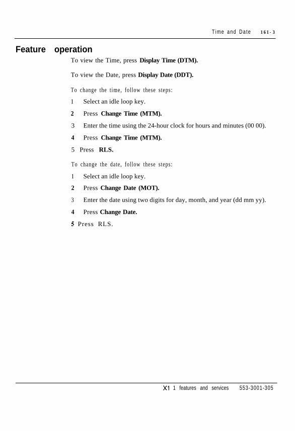
T ime and Da te 161-3
Feature operationTo view the Time, press Display Time (DTM).
To view the Date, press Display Date (DDT).
To change the t ime, fol low these steps:
1 Select an idle loop key.
2 Press Change Time (MTM).
3 Enter the time using the 24-hour clock for hours and minutes (00 00).
4 Press Change Time (MTM).
5 Press RLS.
To change the date, follow these steps:
1 Select an idle loop key.
2 Press Change Date (MOT).
3 Enter the date using two digits for day, month, and year (dd mm yy).
4 Press Change Date.
5 Press RLS.
Xi 1 features and services 553-3001-305

161-4 T ime and Da te
Xl 1 features and services 553-3001-305
. ‘,., y. ,; : ;:. ;. - .-: _ . I . _ ., ., ., .:. ;:.

Issued: 92 1231Status: StandardXl 1 Release: Al l
162-1
Tones and CadencesA tone is the frequency and level of the sound produced while the telephoneis ringing, providing dial tone or feature activation tones. A cadence definesthe time duration for the on and off phases of a ringing or tone cycle.
A set of basic tones and cadences are available on all systems. Flexible Tonesand Cadences (FTC) in X1 1 release 16 allow the tones to be changed.
Basic Tones and CadencesSpecial dial tone
Special dial tone is supplied by the system to indicate that a request for CallTransfer, Conference, and Ring Again. Special dial tone differs from regulardial tone in that i t has three 128 ms interrupt ions at the beginning of the tone.
Overflow toneOverflow tone may be provided on an optional basis to a s tat ion user whotries to access a trunk group when all t runks are busy, or who attempts toaccess features that are unavailable to his or her telephone. Overflow tone isbest described as a fast sounding busy signal .
Tone buzzingTone buzzing is used in conjunction with such features as Call Waiting andManual Signaling (Buzz) to alert the user by a buzz tone through thetelephone’s loudspeaker. This applies when the telephone is off hook or hasa headset plugged in.
Xl 1 features and services 553-3001-305
:.:
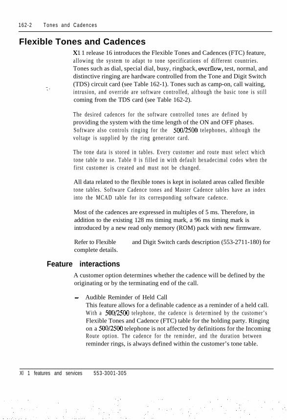
162-2 Tones and Cadences
Flexible Tones and Cadences
: -
Xl 1 release 16 introduces the Flexible Tones and Cadences (FTC) feature,al lowing the system to adapt to tone specif icat ions of different countr ies .Tones such as dial, special dial, busy, ringback, overflow, test, normal, anddistinctive ringing are hardware controlled from the Tone and Digit Switch(TDS) circuit card (see Table 162-1). Tones such as camp-on, call waiting,intrusion, and override are software controlled, al though the basic tone is s t i l lcoming from the TDS card (see Table 162-2).
The desired cadences for the software controlled tones are defined byproviding the system with the time length of the ON and OFF phases.Software also controls r inging for the 500/2500 telephones, al though thevoltage is supplied by the r ing generator card.
The tone data is stored in tables. Every customer and route must select whichtone table to use. Table 0 is f i l led in with default hexadecimal codes when thefirst customer is created and must not be changed.
All data related to the flexible tones is kept in isolated areas called flexibletone tables. Software Cadence tones and Master Cadence tables have an indexinto the MCAD table for i ts corresponding software cadence.
Most of the cadences are expressed in multiples of 5 ms. Therefore, inaddition to the existing 128 ms timing mark, a 96 ms timing mark isintroduced by a new read only memory (ROM) pack with new firmware.
Refer to Flexible and Digit Switch cards description (553-2711-180) forcomplete details.
Feature interactionsA customer option determines whether the cadence will be defined by theoriginating or by the terminating end of the call.
- Audible Reminder of Held CallThis feature allows for a definable cadence as a reminder of a held call.With a 500/2500 telephone, the cadence is determined by the customer’sFlexible Tones and Cadence (FTC) table for the holding party. Ringingon a 500/2500 telephone is not affected by definitions for the IncomingRoute option. The cadence for the reminder, and the duration betweenreminder rings, is always defined within the customer’s tone table.
Xl 1 features and services 553-3001-305

Tones and Cadences 162-3
- Call Park Recall and Group Call RingRecall Ring and Group Call Ring will be given special entries in the FTCtable. New entries will be added to the FTC overlay (LD56) to define thecadence for SL-1, digital, and 500/2500 telephones. The new Recall Ringentry will be used to ring a telephone when recalling a Parked Call.
- Ringing Based on Incoming RouteEnhanced Flexible Tones and Cadences (EFTC) allows the route’s tonetable to determine the cadence and ringing frequency for incoming calls .
- lo-Phase CadenceProgramming of software controlled cadences expands with EFTC from4 intervals to 10, offering greater versatility with the cadences andcadence phases. This affects all cadences under software control.
Operating parametersThe tones that can be produced are l imited to which tones are available on theparticular TDS card being used.
Gradual level change is not allowed when a tone is activated.
If the Distinctive Ringing package is equipped, and a trunk route isclassmarked for that feature, the cadence chosen for each call comes from thesame tone table as for a normal call . The Distinctive Ringing field determinesthe cadences.
If a parked call was originally distinctive, and FTC is equipped, then the CallPark Recall cadence takes precedence. If FTC is not equipped, then thedist inct ive precedence r inging is given.
Because Enhanced Flexible Tones and Cadences (EFTC) is an enhancementof Flexible Tones and Cadences (FTC), the FTC package must be equipped.
Feature packagingFlexible Tones and Cadences (FTC), package 125, has no feature packagedependencies.
Xi 1 features and services 553-3001-305
. . . .:

162-4 Tones and Cadences
Feature implementationRefer to Flexible Tone and Digit Switch cards description (553-2711-180).
Table 162-lHardware controlled tones (Part 1 of 2)
“ione
Dial tone
Message Waiting dial tone
Call Forward dial tone
Ca l l Forward MessageWaiting dial tone
Control Dial tone
Busy tone
Ringback tone
ACD RGA Ringback tone
Over f low tone
LDN tone
Camp-On tone
Camp-On Conf i rm tone
Description
Indicates the system can accept dialing.
Indicates a message is waiting at the message center.
Indicates that the user has call forwarded the phone.
Indicates that the user has call forwarded the phone and amessage is waiting at the message center.
Used for broker service to indicate a control digit is required afterthe switchhook (only for 2500-type telephones with Digitone classof service).
Indicates that the called DN is busy.
Given to the calling party while the called party is ringing. Alsogiven to CO trunks waiting for the DN to answer.
Given to a caller to an ACD group when entering the waiting callqueue and having RGA (Ring Again).
Indicates that the trunk route is busy, or the DN is blocked,disabled, or that a not-allowed action has been carried out.
indicates to a CAS attendant that the incoming call is a Listed DN(LDN) call from a remote site.
Provided as an initial burst when the attendant extends a call to abusy DN that is not equipped with the Call Waiting feature.
Confirms to a CAS attendant that a call to a busy DN at remote, site has camped on, or that the called DN has not answered after
a specified time and the calling party has come back.
Xl 1 features and services 553-3001-305
:
: . . .:
1. ,,. .

Table 162-l
Tones and Cadences 162-5
Hardware controlled tones (Part 2 of 2)
Tone
Dial “0” Recall tone
Description
Indicates to a CAS attendant that a call is a recall occurring dueto attendant recall or call forward busy to attendant from remotesite.
Hold Confirm tone Indicates to a CAS attendant that a call placed on silent hold hastimed out and is recalling.
Test tone I Provided during testing of trunk circuits.
1 Distinctive Ring tone 1 Used to differentiate between routes. I
Norma l R ing tone Provided for internal calls and incoming calls if distinctive ringingor precedence ringing is not in use.
Xi 1 features and services 553-3001-305
:

162-6 Tones and Cadences
Table 162-2Software controlled tones
Tone
Agent Observe tone
Call WaitlTg tone
Intrusion tone
Description
Given to an agent being observed by a supervisor
Indicates to a busy station that another call is coming in.
Provided when the attendant initiates the Barge-In, BusyVerify, or Break-In feature.
Over r ide tone Provided when a user operates the Override key andenters the conversation of a busy extension.
Observe B lock ing tone Given to the supervisor who encounters blocking whileattempting to observe an agent.
Off Hook Queuing tone Given to the call originator when the call enters theof f -hook queue.
Set Relocate tone Given after all information needed to relocate the phone isgiven and proven to be correct. Also given to indicate all iscorrect after plugging the phone back in at the relocatedTermina l Number (TN)
Telset Messaging Alert tone Indicates to caller that telset messaging facilities havebeen entered.
Telset Messaging OK tone Indicates to caller that the message has been receivedcorrectly and everything is fine.
Tel Status Update tone
Special Dial tone
Indicates a successful status update process.
Indicates the availability of a special function such asConference, Transfer, etc.
Expens ive Route Warn ing tone
ACD Call Force tone
When Automatic Route Selection is in use, indicates thatall inexpensive routes are busy and an expensive routemust be chosen to complete the call.
Indicates to the ACD agent that the current call has beendisconnected and a new caller is about to be given to theagen t .
Xl I features and services 553-3001-305
. ..- ..:
,:

Issued: 92 12 31Status: StandardXl 1 Release: 14
Tones, Flexible Incoming163-1
When a telephone is off hook, the user is alerted to a second incoming call bya buzz tone. Flexible Incoming Tones (FIT) allows the replacement of thestandard buzz tone with a buzz with an on/off cadence. This feature is definedon an individual te lephone basis .
When a cal l is presented to a telephone in any of the fol lowing si tuat ions, atone with a special cadence alerts the user:
- Call on DN key while busy on another DN
- Call to a station that is off hook
- Call Park recall when station is busy on another DN
- Call on Group Call key while busy on another call
- Call Waiting
- Call on Dial Intercom key while busy on another call
The buzz cadence is the same as the r inging cadence that applies to aparticular kind of call. For example, if a user receives a call that is a GroupCall, FIT alerts users with a buzz cadence unique to group calls. If the userreceives a call on the Call Waiting key, FIT provides a buzz cadence \signifying call waiting.
Xi 1 features and services 553-3001-305
163-2 Tones , F lex ib le Incoming
Operating parametersFlexible Incoming Tones applies only to SL-1 and Meridian digitaltelephones.
Flexible Incoming Tones does not apply to the following:
- ACD call forcing
- ACD agent receiving a call on ASP key
- ACD supervisor receiving a call on AMG key
- Manual signaling
- Signal Source act ivated by an at tendant console
- Ring Again
Digital telephones in Handsfree mode receive the regular buzz, even if FIT isenabled.
The telephone buzzes with a cadence only if the customer and telephoneoptions are activated. If either option is off, the telephone receives thestandard buzz.
Feature interactions- ACD
If an ACD agent telephone has FIT allowed and is ei ther off hook in thehandset mode, or has the headset plugged in, the agent receives a buzzcadence when a new call is presented. If FIT is not allowed, the agenttelephone receives the standard buzz tone.
Dial Intercom GroupsFor Dial Intercom Group (DIG) calls with the voice (V) option, if thetelephone receiving the call is busy, the user hears one buzz followed bya flashing indicator. This is how DIG works with or without FIT.
Feature packagingThis capability is included in basic X11 system software.
Xi 1 features and services 553-3001-305
.:

Tones , F lex ib le Incoming 163-3
Feature implementation
LD15 -Allow or deny Flexible Incoming Tones (FIT) at the customer level.
REQ
TYPE
C U S T
OPT
C H G Change
C D B Cus tomer Da ta B lock
o-99 Customer number
SBA, (SBD) FIT allowed (denied) for SL-1 sets
DBA, (DBD) FIT allowed (denied) for Meridian digital telephones
LDll - Allow or deny Flexible Incoming Tones for SGl and Meridian digital telephones.
REQ C H G Change
TYPE aaaa Telephone type
aaaa = SLl, 2006,2008,2009,2016,2018,2112,2216,2317,2616,3000
T N lscu Termina l Number
CLS FITA, (FITD) FIT allowed (denied)
Feature operationThere is no specific procedure required to operate this feature.
Xl 1 features and services 553-3001-305

163-4 Tones , F lex ib le Incoming
Xl 1 features and services 553-3001-305

Trunk Verification from a StationTrunk Verification from a Station (TVS) provides the capability for aclassmarked 2500 type telephone to seize a particular trunk within a trunkgroup, receive a dial tone, and outpulse digits to complete a call to a remotemaintenance site. This feature is used as part of a PC-based NetworkManagement system to allow physical testing of each trunk in the network.
Any compatible, customer provided PC-based PBX administration andmaintenance system accesses the trunk to be tested and calls a remotelylocated customer provided responder. The responder supplies the varioustones needed to perform the trunk test . The PC then stores and processes theresults . Once the test ing is complete, the PC disconnects from the tested trunkand accesses the next trunk in the route.
To the system, the PC appears as a 2500 type telephone which requires thecapability to seize a particular trunk member within a trunk route.
Operating parametersIt is recommended that the telephone with a Trunk Verification Allowed(TVA) class of service also have CFW All Calls To External DN Denied(CXFD), CFW Busy Denied (FBD), and CFW No Answer Denied (FND)class of service. This setup prevents any restricted telephone from accessingtrunks by call ing the TVA telephone and subsequently gett ing transferred orforwarded.
Also, it is strongly recommended that this unit not be configured with anLPA. This will prevent the unit from initiating the PBXT (test messagewaiting lamps) command in LD32.
Xl 1 features and services 553-3001-305

164-2 Trunk Verification from a Station
The telephone with a Trunk Verification Allowed (TVA) class of serviceshould also be assigned Warning Tone Denied (WTD) class of service. Thiswill prevent Attendant Busy Verification, which could impair the trunkfrequency measurements that take place during a TVS call . This also preventsthe trunk that this telephone has seized from being barged into by theat tendant .
Feature packagingTrunk Verification from a Station (TVS), package 110, has no featurepackage dependencies.
Feature interactionsThe environment in which the TVS feature will be invoked is a machineenvironment. That is , the user of the 2500 type telephone with this feature wil lusually be a PC-based maintenance system. Therefore, minimal interactionexists with other features.
When the 2500 type telephone with a TVA class of service makes a TVS call ,any Trunk Group Access Restr ict ions/Trunk Access Restr ict ion Groups(TGAR/TARG) restrictions defined in the system are removed for this call.
When a trunk group is busied out by an Attendant console, access to that t runkgroup is not allowed with the TVS feature.
Feature implementation
LDlO - Allow or deny Trunk Verification from a 2500 telephone.
R E Q
TYPE
T N
CLS
C H G Change
500 Te lephone type
lscu Termina l Number
TVA, (TVD) Allow (Deny) TVS
D T N Digitone service is required for 2500 telephones
Xl 1 features and services 553-3001-305
Trunk Verification from a Station 164-3
Feature operationTo verify that a trunk is working properly (from a 2500 telephone with TVAClass of Service), follow these steps:
1 Lif t the handset .
2 Dial SPRE + 70 + ACOD + mmm
where:
SPRE is the special function access prefix70 is the special access code for the TVS featureACOD is the access code of the trunk group to be testedmmm is the number of the trunk member that is to be seized, mmm
must be three digits (001, for example)
Xl 1 features and services 553-3001-305
. . . . : .

164-4 Trunk Verification from a Station
Xl 1 features and services 553-3001-305
:
:. . .-

Uninterrupted Line ConnectionsUninterrupted Line Connections are connections assigned Warning ToneDenied (WTD) Class of Service. The feature prohibits the imposition of anycamp-on or intrusion tones on that l ine.
This feature is recommended for modem or data lines.
Operating parametersThere are no feature requirements.
Feature interactions- Barge-In, Busy Verify, and Override
These features cannot be applied to stations with a WTD class of service.
- Camp OnA call can be camped-on to a station with a WTD class of service, buttone is not provided.
Feature packagingThis capability is included in basic Xl 1 system software.
Xl 1 features and services 553-3001-305
. . - : . .
I

165-2 Unin ter rupted L ine Connect ions
Feature implementation
LDlO - Assign Warning Tone Allowed for 5OOl2500 telephones.
R E Q C H G Change
TYPE I-- 5 0 0 Telephone type
T N l s c u Termina l Number
CLS WTD, (WTA) Warn ing tone denied (a l lowed)
LDll- Assign Warning Tone Allowed for SL-1 and Meridian digital telephones.
R E Q
TYPE
T N
C L S
C H G
aaaa
l s c u
WTD, (WTA)
Change
Te lephone type
aaaa = SLI ,2006,2008,2009,2016,2018,2112,2216,2317,2616,3000
Termina l Number
Warn ing tone denied (a l lowed)
LD14- Assign Warning Tone Allowed for t runks.
R E Q
TYPE
T N
C L S
C H G
aaa
l s c u
VVTD, (WTA)
Change
Trunk typeaaa = ADM, AID, ATVN, AWR, CAA, CAM, COT, CSA, DIG,DID, FEX, ISA, MDM, MUS, PAG, RAN, RCD, RLM, RLR,TIE. WAT
Termina l Number
Warn ing tone denied (a l lowed)
Feature operationNo procedure is required for this feature to operate.
Xl 1 features and services 553-3001-305

User Selectable Call RedirectionX 11 release 19 and later includes User Selectable Call Redirection (USCR),which enhances the implementation of several existing features. First, itenables the user to modify DNs at the telephone for the followingredirections:
- Flexible Call Forward No Answer DN (FDN)
- Hunt DN (HUNT)
- External Flexible Call Forward No Answer DN (EFD)
- External Hunt DN (EHT)
The Stat ion Control Password feature must be act ive, with passwords definedin LD15, for the user to change these redirection DNs.
Second, it expands the number of selectable Ringing Cycle Options (RCOs)for Flexible Call Forward No Answer (CFNA) from one to three.
User assignment of redirection DNsPrior to X1 1 release 19, changing the redirection DNs for FDN, HUNT, EFD,and EHT required a service change to LDs 10 and 11. USCR permits the userto modify any of these four numbers from a rotary, pushbutton, or digitaltelephone.
Depending on the type of telephone, there are three ways to access thisfeature: using a Special Service Prefix Code (SPRF 99 15), a Flexible FeatureCode (FFC), or the User Selectable Redirection (USR) key. The USR key isavai lable only on digi ta l te lephones.
The user can also change the RCO from a telephone after accessing USCR.For securi ty reasons, the user must enter the Stat ion Control Password(SCPW) before changing the redirection DNs or the RCO.
Xl 1 features and services 553-3001-305
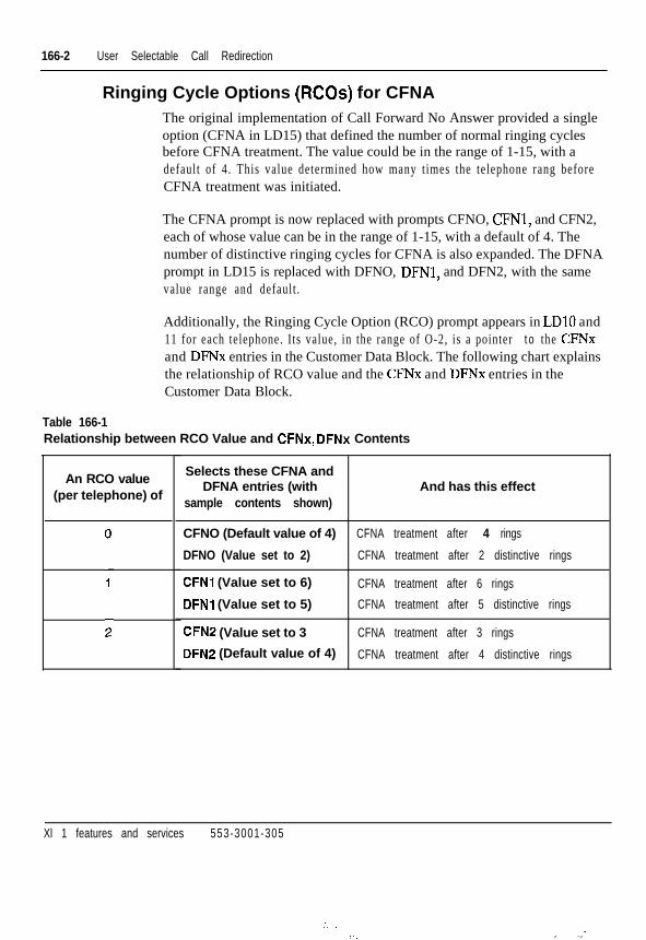
166-2 User Selectable Call Redirection
Ringing Cycle Options (RCOs) for CFNAThe original implementation of Call Forward No Answer provided a singleoption (CFNA in LD15) that defined the number of normal ringing cyclesbefore CFNA treatment. The value could be in the range of 1-15, with adefault of 4. This value determined how many t imes the telephone rang beforeCFNA treatment was initiated.
The CFNA prompt is now replaced with prompts CFNO, CFNl, and CFN2,each of whose value can be in the range of 1-15, with a default of 4. Thenumber of distinctive ringing cycles for CFNA is also expanded. The DFNAprompt in LD15 is replaced with DFNO, DFNl, and DFN2, with the samevalue range and default .
Additionally, the Ringing Cycle Option (RCO) prompt appears in LDlO and11 for each telephone. Its value, in the range of O-2, is a pointer t o the CFNxand DFNx entries in the Customer Data Block. The following chart explainsthe relationship of RCO value and the CFNx and DFNx entries in theCustomer Data Block.
Table 166-1Relationship between RCO Value and CFNx, DFNx Contents
An RCO value Selects these CFNA and
(per telephone) ofDFNA entries (with And has this effect
sample contents shown)
CFNO (Default value of 4) CFNA treatment after 4 rings
DFNO (Value set to 2) CFNA treatment after 2 distinctive rings
CFNl (Value set to 6) CFNA treatment after 6 rings
DFNl (Value set to 5) CFNA treatment after 5 distinctive rings
CFN2 (Value set to 3 CFNA treatment after 3 rings
DFN2 (Default value of 4) CFNA treatment after 4 distinctive rings
Xl 1 features and services 553-3001-305
:.... , _.-

User Selectable Call Redirection 166-3
Operating parametersTo assign or print the RCO for a telephone requires that it have the FlexibleCall Forward No Answer Allowed (FNA) Class of Service or MessageWaiting Allowed (MWA) Class of Service.
The user’s telephone must have User Selectable Redirection Allowed(USRA) class of service and a Station Control Password (SCPW). The usermust enter the correct password to access USCR.
BRI telephones do not support USCR because they cannot access SPRE orFFC, and have no feature keys. Therefore BRI telephones will always use theentries for CFNO and DFNO.
The user cannot use USCR to init ial ly configure call redirection features. Thefeatures must be equipped, and the initial call redirection DNs must beestablished, via a service change.
This feature cannot be used remotely. A user can only change redirection DNsor the RCO for the telephone being used to access USCR.
Feature interactions- Autodial
USCR does not support Autodial; it cannot be used to dial all or part ofthe digits for USCR programming.
Attendant Adminis t ra t ionAttendant Adminis t ra t ion does not support ass igning the USR key, RCO,or USRAKJSRD Class of Service.
Call Forward All CallsWhen CFW redirects a call from telephone A to telephone B, andtelephone B does not answer, the RCO of telephone B determines howlong i t r ings. After the designated number of r ings, the FDN of telephoneA redirects the call.
- Call Forward by Call Type (CFCT)USCR enables a user to assign EFD from the telephone.
Xi 1 features and services 553-3001-305

166-4 User Selectable Call Redirection
-_
- Call Forward No Answer/ Flexible Call Forward No AnswerIn X11 release 19 and later, the single parameters previously used todefine normal ringing cycles (CFNA) and distinctive ringing cycles(DFNA) are expanded to three (CFNO-2 and DFNO-2), with the RingingCycle Options (RCO) parameter used to select the specific CFNA andDFNA entries for each telephone.
- Call Forward No Answer, Second Level (SFA)The number of ringing cycles before SFA is determined by the RCO forthe ringing DN, as with CFNA.
- Dial Access to Features and ServicesThe 9915 feature code accesses USCR from a 500/2500 or a digitaltelephone. The user dials this code after dialing the SPRE.
- Distinctive/New Distinctive RingingThe single parameter previously used to define dist inctive r inging cycles(DFNA) is expanded to three (DFNO-2), wi th the Ringing Cycle Opt ions(RCO) parameter used to select the specific DFNA entry for eachtelephone.
- Enhanced Hot Line and Flexible Hot LineA 500/2500-type telephone with a hot line feature cannot use USCRbecause i t cannot access any features through SPRE or FFC.
- HuntingUSCR permits a user to alter the HUNT DNs or EHT from a telephone.
- Message Center (MC) and Message WaitingUSCR affects the number of times the DN rings before the call isforwarded to the Message Center. The RCO in the TN block of theMARP for the called DN determines the number of times the DN rings.
- Multiple Appearance Redirection Prime (MARP)When a multiple appearance DN is rung, the determination of thenumber of ringing cycles for CFNA depends on the value of the MARPprompt in LD17. If the value is “YES”, the number of ringing cycles isdetermined by the RCO number of the DN that is classified as a MARPTN. If the DN is a Multiple Appearance DN (MADN), the RCO valuesin the other TN blocks for that DN are ignored.
If the MARP value is “NO”, the RCO is taken from the first TN in theDN block with a primary appearance of the DN. If none, then the last TNin the DN block is used.
Xi 1 features and services 553-3001-305

User Selectable Call Redirection 166-5
- PretranslationIf Pretranslation (package 92)is enabled, the digits entered as theredirection DN are pretranslated before they are stored. Note that nopretranslation occurs when the redirection DNS are used in such callprocessing features as Hunting or CFNA, el iminat ing the possibi l i ty thatthe redirection DN is pretranslated twice.
- Short HuntingUSCR does not support changing the HUNT or EHT for a telephone withshort hunt enabled. USCR also does not support entering ‘000’ from atelephone as the HUNT.
- SpeedcallSpeedcall is not supported by USCR.
Feature packagingUser Selectable Call Redirection is available as part of X11 release 19.Flexible Feature Codes (FFC) (package 139) is a prerequisite for the useractivat ion part of this feature because i t provides for the Stat ion ControlPassword.
Xl 1 features and services 553-3001-305
: . . . . :. .:

166-6 User Selectable Call Redirection
Prompt
R E Q
TYPE
R C O
SCPW
CLS
Feature implementationResponses to the LD prompts shown in the fol lowing tables set . up USCR.Responses differ depending on the type of telephone and the type of accessbeing set up.
LDlO - Setting up USCR for 500/2500 telephones
Response Comments
N E W , C H G New or change
500 Type of telephone
(01, 1,2 Ringing Cycle Option for CFNA, inthe range of O-2, with a default of 0
xxx...xx Sta t ion Cont ro l Password
USRA, (USRD) User Selectable Redirection class ofservice (permitting SPRE and FFCaccess) allowed or denied
Note: The craftsperson can use easy change to change the RCO andUSRA/USRD CL6 At the ITEM prompt, type RCO <value> where value is O-2.
Xi 1 features and services 553-3001-305
.
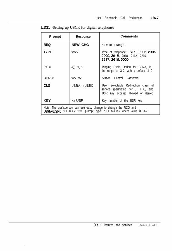
User Selectable Call Redirection 166-7
LDll -Setting up USCR for digital telephones
Prompt Response
REQ NEW, CHG
TYPE xxxx
Comments
New or change
Type of telephone: SLl, 2006,2008,2009,2016, 2018, 2112, 2216,2317,2616,3000
R C O 0% 1, 2 Ringing Cycle Option for CFNA, inthe range of O-2, with a default of 0
SCPW
CLS
xxx...xx Station Control Password
USRA, (USRD) User Selectable Redirection class ofservice (permitting SPRE, FFC, andUSR key access) allowed or denied
KEY xx USR Key number of the USR key
Note: The craftsperson can use easy change to change the RCO andUSRA/USRD CLS. At the ITEM prompt, type RCO <value> where value is O-2.
Xi 1 features and services 553-3001-305
:

166-8 User Selectable Call Redirection
LD15 -Setting up USCR in the Customer Data Block
Prompt Response
R E Q N E W , C H G
TYPE C D B
CUST xx
C F N O xx
Comments
New or change
Cus tomer Da ta B lock
Customer number (O-99)
Number of normal rings for CFNA,Option 0 (l-l 5; default is 4)
CFNI xx Number of normal rings for CFNA,Option 1 (1-l 5; default is 4)
C F N 2 xx Number of normal rings for CFNA,Option 2 (I-l 5; default is 4)
D F N O xx Number of distinctive rings forDFNA, Option 0 (l-1 5; default is 4)
DFNI xx Number of distinctive rings forDFNA, Option 1 (l-1 5; default is 4)
D F N 2 xx
SCPL W3
Number of distinctive rings forDFNA, Option 2 (l-l 5; default is 4)
Length of Station Control Password.If O=password disabled; cannot useU S C R
Xl 1 features and services 553-3001-305
. . .: .: :
-. _ . . :

User Selectable Call Redirection 166-9
LD57 - Setting up USCR
Prompt
REQ
C U S T
C O D E
U S C R
U S C R
U S C R
Response
N E W , C H G
xx
USCR, ALL
xxxxxxx
YYYYYYY
<cr>
Comments
New or change
Customer number (O-99)
Prompt for USCR FFC, or all FFCcode types
USCR FFC (1-7 digits)
Define additional FFC codes, asneeded
Ends the entry of FFC codes
Feature operationAs a prerequisi te to accessing the feature, the condit ions shown in Table166-2 must be met for the selected access method.
Table 166-2Requirements for accessing USCR
Requirement
FFC package equ ipped
SCPL is defined (>O)
SCPW is de f ined
Telephone has USR key
USRA class of service defined
SPRE def ined
USCR FFC de f i ned
USR Key
Yes
Yes
Yes
Yes
Yes
No
No
Access Method
SPRE
Yes
Yes
Yes
No
Yes
Yes
No
FFC
Yes
Yes
Yes
No
Yes
Yes
Yes
1
X1 1 features and services 553-3001-305
,.

166-10 User Selectable Call Redirection
Procedure 166-lTo assign/query a redirection DN using SPRE:
1 Take the telephone off-hook, or press the DN key on a digitalte lephone.
2 En te r the SPRE
3 Enter the USCR feature access code (9915)
4 Enter the Station Control Password.
5 Enter the USCR Option Code, as shown in Table 166-3.
Table 166-3USCR option codes
I 2I
HUNT redirection DNI
3 EFD redirection DN
4 EHT redirection DN
1 5 1 RCO
6 Enter new RCO if assigning the RCO; enter redirection DN if assigningthe DN.
7 Place telephone on-hook, or press the RLS key on a digital telephone.
Procedure 166-2To assign or query a redirection DN using the USR key:
1 Press the dark USR key.
2 Enter the Station Control Password.
3 Enter the USCR option code from Table 166-3.
4 Enter new RCO if assigning the RCO; enter redirection DN if assigningthe DN.
5 Press the USR key again.
Xl 1 features and services 553-3001-305
:,
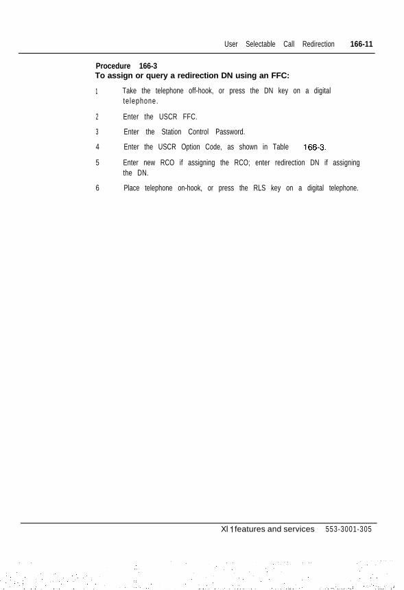
User Selectable Call Redirection 166-11
Procedure 166-3To assign or query a redirection DN using an FFC:
1 Take the telephone off-hook, or press the DN key on a digitalte lephone.
2 Enter the USCR FFC.
3 Enter the Station Control Password.
4 Enter the USCR Option Code, as shown in Table 166-3.
5 Enter new RCO if assigning the RCO; enter redirection DN if assigningthe DN.
6 Place telephone on-hook, or press the RLS key on a digital telephone.
Xl 1 features and services 553-3001-305

166-12 User Selectable Call Redirection
. .
Xl 1 features and services 553-3001-305
2::; _. :. ‘.. , ,,:-, *::..., ‘. _

Issued: 93 08 01Status: StandardXl 1 Release: 1
-a: 1
Voice Call167-1
Voice Call allows you to talk through the speaker of a Meridian digitaltelephone from another Meridian digital telephone. The called party does nothave to l if t the handset to hear you. For a two-way conversation, the calledparty must l if t the handset or activate Handsfree, unless Handsfree Voice Callis enabled.
If the called telephone is busy on another DN, the caller hears continuousringing. The called party hears a single beep and the Voice Call DN keyflashes. If the telephone is busy on the Voice Call DN, the caller hears a busytone. A fast busy tone may indicate that the Voice Call DN is no longeravailable (it may not be a single appearance DN).
Handsfree Voice CallHandsfree Voice Call is an Xl 1 release 19 system feature that can be usedwith such telephones as the M2112, M23 17, and M26 16.
Handsfree Voice Call provides the option of configuring VCUDIG (withvoice option) to be answered in either handsfree mode or loudspeaker onlymode. Calls answered in handsfree (HVA) mode establish a two-way voicepath, while those answered in loudspeaker only (HVD) mode establish onlya one-way voice path from the call ing telephone to the destination telephone.
Xl 1 features and services 553-3001-305
167-2 Vo ice Ca l l
Operating parametersBoth te lephones must be Meridian digi ta l te lephones.
The Voice Call DN must be single appearance.
Handsfree Voice Call allowed/denied is set at the system level and can onlybe used with digital telephones that have handsfree capabil i t ies (such asM2112, M2317, M2616). It requires Class of Service HandsfreeAllowed/HFA on the dest inat ion telephone, which is set at the telephonelevel.
Note: BRI, M3000, and SL-1 telephones do not support the Handsfreefeature.
Feature interactions- Manual Signaling
The same DN can be used for both Voice Call and Manual Signaling(Buzz) as long as it remains a single appearance DN.
- Multiple Appearance DNsIf a Voice Call DN is added to a second telephone, the DN becomes aMultiple Appearance DN (MADN). Voice Call no longer works on thatDN and fast busy tone is returned.
- Auto Answer Back (AAB)This feature is not affected by the Handsfree Voice Call feature.
Feature packagingVoice Call requires the Extended PBX Features package (Package 1).
Handsfree Voice Call requires release 19 or above.
Xl 1 features and services 553-3001-305
.,

Voice Call 167-3
Feature implementation
LDll- Add or change Voice Call for the originating SL-1 or Meridian digital telephone,
REQ C H G
TYPE aaaa
T N
K E Y
KEY
l s c u
xx SCR yyy...y
xx vcc yyy...y
Change
Te lephone type
aaaa = SLl ,2006,2008,2009,2016,2018,2112,2216,2317,2616,3000
Termina l Number
Adds a single appearance single call key on theterminat ing te lephone
xx = key numberyyy...y = the DN assigned to the Voice Call key for theor ig inat ing te lephone
Adds a Voice Call key on the originating telephone
xx = key numberyyy...y = the DN of the terminating telephoneThis key activates the feature.
LD15 - Add or change Handsfree Voice Call for the Meridian 1 system.
R E Q
TYPE
CUST
OPT
C H G
CDS
0
HVA, (HVD)
Change
Customer data block
Cus tomer number
Sys tem op t ion HVA
Xl 1 features and services 553-3001-305
::.,:.

167-4 Vo ice Ca l l
Feature operationVoice Call and Handsfree Voice Call operations are described below.
Voice CallTo make a Voice Call:
- Lift the handset and press Voice Call. The DN is automatically dialed. Ifthe cal led telephone is busy on another DN, you hear continuous r inging.If the telephone is busy on the Voice Call DN, you hear busy tone.
To end a Voice Call:
- Press FUS.
To answer a Voice Call on an idle telephone:
- Let the call ring once. The call is answered automatically, activating theVoice Call DN over the speaker. For a two way conversation, lift thehandset .
If busy on another DN, you hear a single beep and the Voice Call DNflashes. You must end your present call to receive the Voice Call.
Handsfree Voice CallExamples of both Handsfree Voice Call options are listed below:
HVA optionThe originating telephone (telephone A) places a VCC/DIG call to thedestination telephone (telephone B).
- Telephone B rings once.
- After one ring, telephone B automatically answers the call in Handsfreemode.
The DN and Handsfree LCDs are lit and a two-way voice path isestabl ished.
Xl 1 features and services 553-3001-305

Voice Ca l l 167-5
HVD optionTelephone A places a call to telephone B.
- Telephone B rings once.
- After one ring, telephone B automatically answers the call in loudspeakeronly mode.
The DN LCD is lit and the Handsfree LCD remains dark, establishing aone-way voice path from telephone A to telephone B. At this point ,telephone A is unable to hear the person at telephone B.
To re-establish a two-way voice path, telephone B must either gooff-hook, or press the Handsfree button.
Note: Busy calls are not changed by Handsfree Voice Call.
Xi 1 features and services 553-3001-305

167-6 Vo ice Ca l l
Xl 1 features and services 553-3001-305

Issued:Status:Xl 1 Release:
2500 Telephone Features168-1
This feature allows 2500-type telephones to access features otherwiseavailable only with SL- 1 and Meridian digital telephones. By dialing anoctothorpe (#) and a single digit access code, 2500 type telephones can accessthe following features:
- Call Forward All Calls Dial #l
- Speed Call Controller Dial #2
- Speed Call User Dial #3
- Permanent Hold Dial #4
Operating parametersAllow or deny these features in LDlO (500/2500 telephone administration).
Except for the access codes used, feature operation is the same as SL- 1 andMeridian digi ta l te lephones.
Xl 1 features and services 553-3001-305

168-2 2500 Telephone Features
Feature interactions500 Set FeaturesWhen 500 Set Features (SS5), package 73, is equipped, 2500-typetelephones also access by dialing SPRE and a two-digit access code asfollows:. System Speed Call User SPRE + 73. Call Forward All Calls SPRE + 74. Speed Call Controller SPRE + 75. Speed Call User SPRE + 76. Permanent Hold SPRE + 77
Remote Call ForwardWhen Flexible Feature Codes (FFC), package 139, is defined andactive on your system, a telephone provisioned for Call Forward in LD10 can also Call Forward All Calls from a remote internal DN.
Feature packaging2500 Set Features (SS25), package 18, has no feature package dependencies.
Xi 1 features and services 553-3001-305
:

2500 Telephone Features 168-3
Feature implementation
LDlO - Enable 2500 Set features
R E Q
TYPE
T N
CLS
F T R
C H G
500
l s c u
XFA, (XFD)
CFW xx
see xxxx
scu xxxx
ssu xxxx
P H D
Change
Te lephone type
Termina l Number
Allow or deny transfer
Call Forward All Calls and DN length (4-23)
X CFW to remove
Speed Call Controller and list number
X SCC to remove
Speed Call User and list number
X SCU to remove
System Speed Call User and list number
X SSU to remove
Al low Permanent Ho ld
X PHD to remove
Xl 1 features and services 553-3001-305
.,. ., -:. ,I.,

168-4 2500 Telephone Features
Feature operationCall Forward All Calls
Case 1: FFC active, CFW not activeOn a telephone with Flexible Feature Codes implemented but without CallForward currently active, use these steps to activate the feature:
1 Lift the handset and dial SPRE + 74. You hear a dial tone.
2 Dial the DN where you want calls to be forwarded. The dial tonedisappears.
3 Hang up to complete the act ivat ion.
To deactivate Call Forward, follow these steps:
1 Lift the handset and dial SPRE + 74. You hear a dial tone.
2 Hang up to complete deact ivat ion.
Case 2: FFC not active, CFW not activeOn a telephone without Flexible Feature Codes or Call Forward currentlyActive, use these steps to activate the feature:
1 Lift the handset and dial #l. You hear a dial tone.
2 Dial the DN where you want calls to be forwarded. The dial tonedisappears.
3 Hang up to complete the act ivat ion.
To deactivate Call Forward, follow these steps:
1 Lift the handset and dial #l. You hear a dial tone.
2 Hang up to complete deact ivat ion.
Case 3: FFC active, CFW activeOn a telephone with Flexible Feature Codes and Call Forward currentlyactive, use these steps to deactivate the feature:
1 Lift the handset and dial #l. You hear a confirmation tone.
2 Hang up to complete the deact ivat ion.
Xi 1 features and services 553-3001-305
:

2500 Telephone Features 168-5
To reactivate Call Forward, follow these steps:
1 Lift the handset and dial #l. You hear a dial tone.
2 Dial the DN where you want calls to be forwarded. The dial tonedisappears.
3 Hang up to complete the act ivat ion.
1 Lift the handset and dial #l. You hear a dial tone.
2 Dial the DN where you want calls to be forwarded. The dial tonedisappears.
3 Dial the EOD string. You hear a confirmation tone.
4 Hang up to complete the act ivat ion.
1 Lift the handset and dial #l. You hear a dial tone.
2 Hang up to complete the activation. Calls are forwarded to the last CA11Forward DN used by this telephone.
Speed Call ControllerTo update a predefined Speed Call list, follow these steps:
1 Lift the handset, dial #2. You hear a dial tone.
2 Dial the Speed Call code (O-999) followed by the phone number itrepresents. If the entry is accepted, you hear silence. If the entry is notaccepted, you hear a fast busy tone.
3 Hang up.
To change a number associated with a l is t , fol low these steps:
1 Lift the handset, dial #2. You hear a dial tone.
2 Dial the Speed Call code (O-999), followed by the new telephonenumber. The new number automatically replaces the old one. If the entryis accepted, you hear silence. If the entry is not accepted, you hear a fastbusy tone.
3 Hang up.
Xl 1 features and services 553-3001-305
,.

168-6 2500 Telephone Features
To remove an entry from a Speed Call list, follow these steps:
1 Lift the handset, dial #2. You hear a dial tone.
2 Dial the Speed Call code (O-999) you want to remove.
3 Hang up.
Speed Call UserTo make a Speed Call, follow these steps:
1 Lift the handset, dial #3. You hear a dial tone.
2 Dial the Speed Call code (O-999).
3 The number is dialed automatically.
System Speed Call UserTo make a System Speed Call, follow these steps:
1 Lift the handset and dial SPRE 73. You hear a dial tone.
2 Dial the System Speed Call code (O-999).
3 The number is dialed automatically.
Permanent HoldTo activate Permanent Hold while on a call, follow these steps:
1 Flash the switchhook. You hear a dial tone.
2 D ia l #4.
3 Hang up.
The call remains on hold until you lift the handset again, or the other partydisconnects .
Xi 1 features and services 553-3001-305

500 Telephone FeaturesThis feature allows 500 type (rotary-dial) telephones to use Call Forward,Speed Call, and Permanent Hold. Since 500 type telephones do not haveoctothorpe (#I), the following features are activated by dialing SPRE and atwo-digit access code.
- System Speed Call SPRE + 73- Call Forward All Calls SPRE + 74- Speed Call Controller SPRE + 75- Speed Call User SPRE + 76- Permanent Hold SPRE + 77
Operating parametersAllow or deny these features in LDlO (500/2500 telephone administration).
Except for the SPRE codes used, feature operation is the same as with SL-1and Meridian digi tal te lephones.
Feature interactions- 2500 Set Features
When the 2500 Set Features (SS25), package 18, is equipped, 2500-typetelephones also access by dial ing the SPRE and a two digit access code.
Feature packaging500 Set Features (SS5), package 73, requires the following:
- 2500 Set Features (SS25), package 18.
Xl 1 features and services 553-3001-305

169-2 500 Telephone Features
Feature implementation
LDlO- Enable 500 Set Features.
R E Q
TYPE i--.T N
CLS
F T R
C H G
5 0 0
l s c u
XFA, (XFD)
CFW xx
see xxxx
scu xxxx
ssu xxxx
P H D
Change
Te lephone type
Termina l Number
Allow (deny) transfer
Call Forward All Calls and DN length (4-23)
X CFW to remove
Speed Call Controller and list number
X SCC to remove
Speed Call User and list number
X SCU to remove
System Speed Call User and list number
X SSU to remove
Al low Permanent Ho ld
X PHD to remove
Feature operationCall Forward All Calls
To forward your calls, follow these steps:
1 Lift the handset and dial SPRE + 74. You hear the dial tone.
2 Dial the DN where you want your calls forwarded.
3 Hang up.
To cancel forwarding, follow these steps:
1 Lift the handset and dial SPRE -t 74. You hear a dial tone.
2 Hang up.
Xl 1 features and services 553-3001-305

500 Telephone Features 169-3
Speed Call ControllerTo update a predefined Speed Call list, follow these steps:
1 Lift the handset and dial SPRE + 75. You hear the dial tone.
2 Dial the Speed Call code (O-999), followed by the phone number itrepresents. If the entry is accepted, you hear silence. If the entry is notaccepted, you hear a fast busy tone.
3 Hang up.
To change a number associated with a l is t , fol low these steps:
1 Lift the handset and dial SPRE + 75. You hear a dial tone.
2 Dial the Speed Call code (O-999) followed by the new phone number.The new number automatically replaces the old one. If the entry isaccepted, you hear silence. If the entry is not accepted, you hear a fastbusy tone.
3 Hang up.
To remove an entry in a Speed Call list, follow these steps:
1 Lift the handset and dial SPRE + 75. You hear a dial tone.
2 Dial the Speed Call code (O-999) you want to remove.
3 Hang up.
Speed Call UserTo make a Speed Call, follow these steps:
1 Lift the handset and dial SPRE + 76. You hear a dial tone.
2 Dial the Speed Call code (O-999).
3 The number is dialed automatically.
System Speed Call UserTo make a System Speed Call, follow these steps:
1 Lift the handset and dial SPRE + 73. You hear a dial tone.
2 Dial the System Speed Call code (O-999).
3 The number is dialed automatically.
Xl 1 features and services 553-3001-305
;.: :

169-4 500 Telephone Features
x-;.
Permanent HoldTo activate Permanent Hold while active on a call, follow these steps:
1 Flash the switchhook. You hear a dial tone.
2 Dial SPRE + 77.
3 Hang up.
The call remains on hold until you lift the handset again, or the other partydisconnects .
Xl 1 features and services 553-3001-305
_ :
500/2500 Type Line Disconnect170-l
500/2500 Type Line Disconnect is invoked when the Meridian 1 systemdetects on-hook/disconnect supervision from a party connected to a 500/2500type port . Dialtone is sent to this port for a specif ied period of t ime (default is6 seconds) which is defined in LD 15 at the Line Disconnect Tone Timer(LDTT) prompt. Refer to the feature implementation for a list of LD15prompts .
I t is used when the 500/2500 type port is connected to an automated at tendantor voice mail . I t a l lows the Meridian 1 system to know that i t is not connectedto a telephone, and to disconnect if the other telephone has hung up, forexample, during an automated message or a voice mail message.
This feature is programmed in LDlO, LD15, LD20, LD21, LD81, and LD83.Refer to the XI 1 input /output guide (553-300 l -400) for a l is t of these promptsand responses.
Figure 170- 1 illustrates how an incoming trunk call or internal call functionswith 500/2500 Type Line Disconnect.
Xl 1 features and services 553-3001-305
., . .

170-2 500/2500 Type L ine D isconnec t
Figure 170-lincoming Trunk Call of Internal Call Disconnects
Local Central Office
500/2500 Pori
Dial Tone
ian@mli i
Xl 1 features and services 553-3001-305
.‘:’ . . . :’, :

500/2500 Type L ine D isconnec t 170-3
This illustration shows the incoming trunk call or internal call disconnectedand dialtone being provided by the 500/2500 type port with the new Class ofService (CLS) Line Disconnect Tone Allowed (LDTA)
Figure 170-2 illustrates how an outgoing call functions with this feature.
Figure 170-2Outgoing Call from the Meridian 1 to a Central Office
\\
Incoming Call \\
Local Central Office
/ \ Trunk Card \
500/2500 Port
This i l lus t ra t ion shows an outgoing cal l to f rom the Meridian 1 system to theCentral Office. Station A transfers Station B to Meridian Mail and goeson-hook. The dialtone is provided by the 500/2500 type port with the newCLS LDTA after Station B disconnects.
Xi 1 features and services 553-3001-305

170-4 500/2500 Type L ine D isconnec t
Operating parametersA 500/2500 port with LDTA Class of Service 500/2500 receives disconnecttone’in the following cases:
- an incoming internal cal l is placed to an LDTA port and then disconnects
- incoming call from a trunk with disconnect supervision is placed to anLDTA port and then the incoming trunk disconnects
- an internal DN places an outgoing call on a trunk with disconnectsupervision, then transfers the call to the LDTA port and then the trunkdisconnects
Line Disconnect Tone is not provided on outgoing cal ls from the LDTA port .
Feature interactions- Conference/No Hold Conference
If one of the parties in the conference is connected to a 500/2500 port thatis in turn connected to a VRU, dial tone is provided to the 500/2500 portwhen all the other parties in the conference disconnect. This featureenhancement applies in the same way to Call Transfer and Hunting.
- Attendant Extended Call500/2500 Line Disconnect applies if the attendant extends a call to a50012500 port that is connected to a VRU; or the attendant extended acall to a 500/2500 port that is connected to a VRU and remains in the cal l ,and the other party has disconnected.
- 500/2500 ACD agentIf a call is involved with a 500/2500 ACD agent that is connected to aVRU and the other party has disconnected, 500/2500 Line Disconnectapplies. When the other party disconnects, the 500/2500 agent wil l bereturned to the idle agent queue.
Feature packaging500/2500 Line Disconnect is included in basic X11 system software.
Xi 1 features and services 553-3001-305

Feature implementation
50012500 Type Line Disconnect 170-5
LDlO - Allow or deny Line Disconnect Tone for 500/2500 ports.
R E Q C H G Change
TYPE 500 Telephone type
T N l s c u Termina l Number
CLS LDTA, (LDTD) Line Disconnect Tone allowed (denied)
LD15 - Define Line Disconnect Tone timer in the Customer data block.
R E Q C H G Change
TYPE C D B Telephone type
CUST o-99 Customer number
L D T T 2-(6)-30 Line Disconnect Tone timer in seconds
Feature operationNo specific procedure is required for this feature to operate.
Xl 1 features and services 553-3001-305

S L - 1
Xl 1 features and servicesSUPPLEMENT
C o p y r i g h t 0 1 9 8 9 N o r t h e r n T e l e c o mAll rights reserved.I n f o r m a t i o n s u b j e c t t o c h a n g e w i t h o u t n o t i c e .R e l e a s e 8 . 0S t a n d a r dO c t o b e r 3 1 , 1 9 9 3P r i n t e d i n t h e U . S . A .
..::2:: :-.:i:i .A-‘..
.<