PNS/PAES 413: Agricultural Structure - Biogas Plant · Feedlot animal 14.0 ... Liquid cow/carabao...
42
PNS/PAES 413 (2003) (English): Agricultural Structure - Biogas Plant
Transcript of PNS/PAES 413: Agricultural Structure - Biogas Plant · Feedlot animal 14.0 ... Liquid cow/carabao...

REPUBLIC OF THE PHILIPPINES
In order to promote public education and public safety, equal justice for all, a better informed citizenry, the rule of law, world trade and world peace, this legal document is hereby made available on a noncommercial basis, as it is the right of all humans to know and speak the laws that govern them.
EDICT OF GOVERNMENT
PNS/PAES 413 (2003) (English): AgriculturalStructure - Biogas Plant


PHILIPPINE N I 81 R
Agricultural Structure - Biogas Plant
PNS/PAES 413:2003 (PAES published 2001)
DEPARTMENT OF BUREAU OF PRODUCT STANDARDS
TRADE & INDUSTRY PHILIPPINES


PHILIPPINE AGRICULTURAL ENGINEERING STANDARD PAES 413:2001
Agrlicultural Structures - Biogas Plant
1 Scope
This standard specifies the minimum requirements for the design and construction of a biogas plant utilizing animal wastes.
2 Reference
The following normative document contains provisions which through reference in this text constitute provisions of this National Standard:
PAES 414:2002 Agricultural Structures - Waste Management Structures
3 Definition
For the purpose of this standard, the following definitions shall apply:
3.1 biogas plant plant used to process animal wastes or manure to produce biogas and sludge consisting of an inlethnixing tank, digester, gas chamber and outlet/sludge tank
3.2 integrated plant biogas plant where the digester and gas chamber form one unit
3.3 split-type plant digester and gas chamber form separate units
3Q4 multi-digester plant plant with series of digesters
3.5 floating type plant consisting of digester and a moving, floating gasholder that either float directly in the fermenting slurry or in a separate water jacket
3.6 fixed type closed digester with an immovable, rigid gas chamber and a displacement pit
D-93

PAES 413:2001
3.7 balloon type plant consisting of a heat-sealed plastic or rubber bag (balloon), combining digester and gasholder
3.8 collecting tank ho lding tank chamber where manure and water are collected, stored and separated from heavy and nonbiodegradable materials before feeding them into the digester
3.9 inlet pipe serves as conveyor of the manure-water mixture or slurry from the mixing tank to the digester
3.10 digester biodigester bio-reactor anaero bic reactor any water and air tight container designed for the process of anaerobic microbiollogical degradation of organic matter into which the slurry is introduced for digestion and methanization
3.11 baffle board division in the digester that prevent the slurry from premature exit into the sludge/outlet tank
3.12 stirrer mixer agitator mechanical device inside the digester used to stir the slurry
3.13 gas chamber space inside or outside the digester for the collection and storage ofbiogas
3.14 gasbolder retainer cantilever beam that holds the gasholder/movable cover in position at the desired biogas pressure
3.15 outlet pipe serves as conveyor where the effluent or the slurry is forced out
D-94
PAES 413:2001
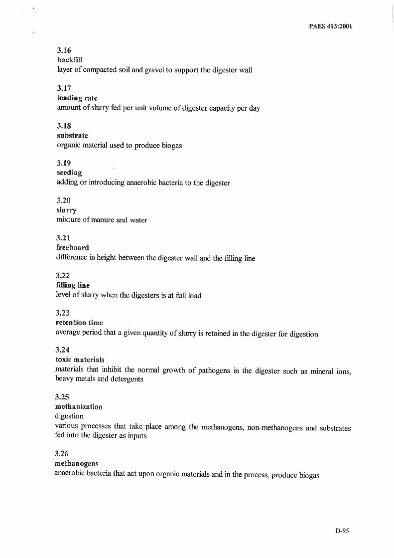
3.16 backfill layer of compacted soil and gravel to support the digester wall
3.17 loading rate amowlt of slurry fed per unit volume of digester capacity per day
3.18 substrate organic material used to produce bio gas
3.19 seeding adding or introducing anaerobic bacteria to the digester
3.20 slurry mixture of manure and water
3.21 freeboard difference in height between the digester wall and the filling line
3.22 filling line level of slurry when the digesters is at full load
3.23 retention time average period that a given quantity of slurry is retained in the digester for digestion
3.24 toxic rnaterials materials that inhibit the normal growth of pathogens in the digester such as mineral ions, heavy :metals and detergents
3.25 metbanization digestion various processes that take place among the methanogens, non-methanogens and substrates fed into the digester as inputs
3.26 metbanogens anaerobic bacteria that act upon organic materials and in the process, produce biogas
D-95

PAES 413:2001
3.27 mesopbilic temperature rage temperature range of 20°C - 40 °C where mesophilic bacteria operates
3.28 gas production rate amount ofbiogas produced per day per cubic meter of slurry
3,,29 hiogas mixture of gas (composed of 50 to 70 percent methane and 30 to 40 percent carbon dioxide) produced by methanogenic bacteria
3.30 scum layer offloatmg material (mainly fibrous) on the slurry
3.31 sludge settled portion or precipitate of the slurry; a mud-like, semi-solid mass
3.32 emuent residue that comes out at the outlet after the substrate is digested/processed inside the digester
4 Classification
4.1 According to plant set-up
4.1,,1 Integrated
4.1.2 Split-type
4.2 According to number of digester
4.2.1 Single-digester
4.2.2 Multi-digester
4$3 According to gas chamber design
Floating type
4.3.2 Fixed type
4.3.3 Balloon type
D-96

4 .. 4 According to feeding method
4.4.1 Continuous-Feed
4.4.1.1l High-Rate Mixed
4.4.1..2 Intermittently Mixed
4.401.3 Unmixed
4.4.2 Batch-Feed, Mixed or Unmixed
4.4.3 Hybrid
4.5 According to buried position
4.5~1 Ground digester
4.5 .. 2 Semi-buried digester
4.5,,3 Underground digester
4 .. 6 According to geometrical shapes
4 .. 6 .. 1 Rectangular type
4.6 .. 2 Cylindrical dome type
4.6 .. 3 Square type
4.6~4 Ellipsoidal type
4.6.5 Spherical type
4.6.6 Octagonal type
4.6.7 Dome top type
4.6.8 Inverted dome type
t:106.9 Rectangular dome type
4 .. 6.10 Cylindrical tube type
PAES 413:2001
D-97

PAES 413:2001
5 Location
5.1 Biogas plant should be located at a site with good drainage.
5.2 It should be located as near as possible to the animal pen and should be lower than elevation of animal pen canal.
5.3 The utilization ofbiogas should be near.
5.4 Soil foundation should be stable and away from tree roots intrusion.
6 Size of biogas components
6.1 Collecting tank volume
6 .. 1.1 For continuous-fed biogas plat, the size of the tank for collecting and separating manure from heavy and non-biodegradable materials should not exceed to the total slurry volume for 10 days. Table 1 shows the estimated daily quantity of animal manure.
6.L2 The slurry volume is the volume occupied by the manure and water at a ratio of 1: 1 (1 kg of manure: 1 L of water).
Table 1 - Estimated daily quantity of available manure
Animals Manure available
kg/day/animal Pigs
Porker, 3-8 months old, mixed ages 2.20 18-36 kg 2.55 36-55 kg 5.22 55-73 kg 6.67 73-91 kg 8.00
Cow Feedlot animal 14.0 Breeding animal 13.0 Work animal 7.50
Buffalo Breeding animal 14.0 Work animal 8.00
Horse Breeding animal 13.50 Work animal 7.75
Chicken Layer, 6 months or older 0.075 Broiler, day-old to 8 weeks 0.025
6.1.3 For batch-fed, the slurry input rate shall be multiplied by the interval of slurry charging.
D-98
PAES 413:2001
6.1.4 Calculation of optimum dimension should follow the same procedure used for digester
tanle
6.2 Inlet pipe
The minimum diameter of the inlet pipe shall be 0.2 m.
6.3 Digester volume
6.3.1 Slurry volume
The digester tank capacity is calculated from the daily slurry volume multiplied by the retention time (Table 2).
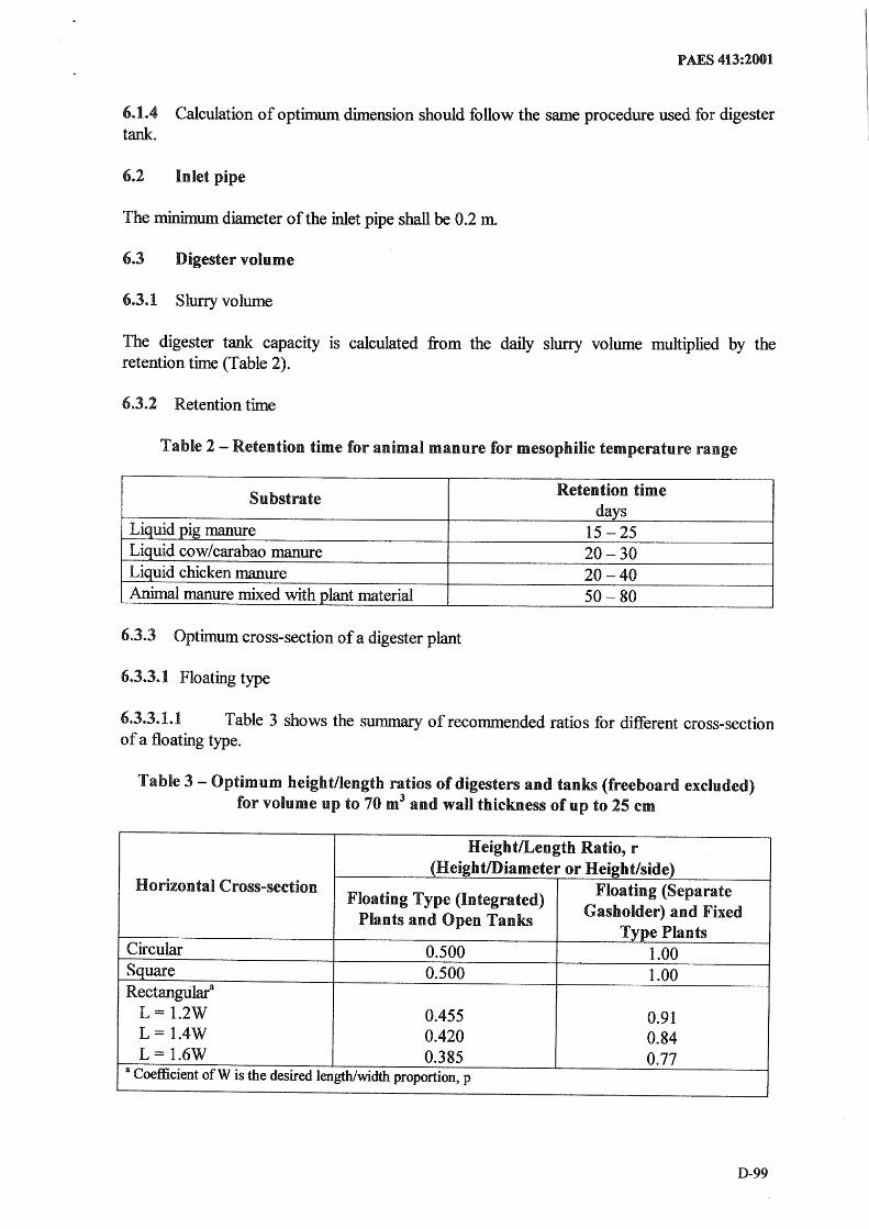
6.3e2 Retention time
Table 2 - Retention time for animal manure for mesophilic temperature range
Substrate Retention time
days Liquid pig manure 15 -25 Liquid cow/carabao manure 20-30 Liquid chicken manure 20-40 Animal manure mixed with plant material 50- 80
6.3&3 Optimum cross-section of a digester plant
6.3,,3.1 Floating type
603.3.1.1 Table 3 shows the summary of recommended ratios for different cross-section of a floating type.
Table 3 - Optimum heightlIength ratios of digesters and tanks (freeboard excluded) for volume up to 70 m3 and wall thickness of up to 25 cm
HeightlLength Ratio, r (HeigbtlDiameter or Height/side)
Horlizontal Cross-section Floating Type (Integrated)
Floating (Separate
Plants and Open Tanks Gasholder) and Fixed
Type Plants Circular 0.500 1.00 Square 0.500 1.00 Rectangtilara
L = 1.2W 0.455 0.91 L = I.4W 0.420 0.84 L = 1.6W 0.385 0.77
a Coefficient of W is the desired length/width proportion, p
D-99
PAES 413:2001
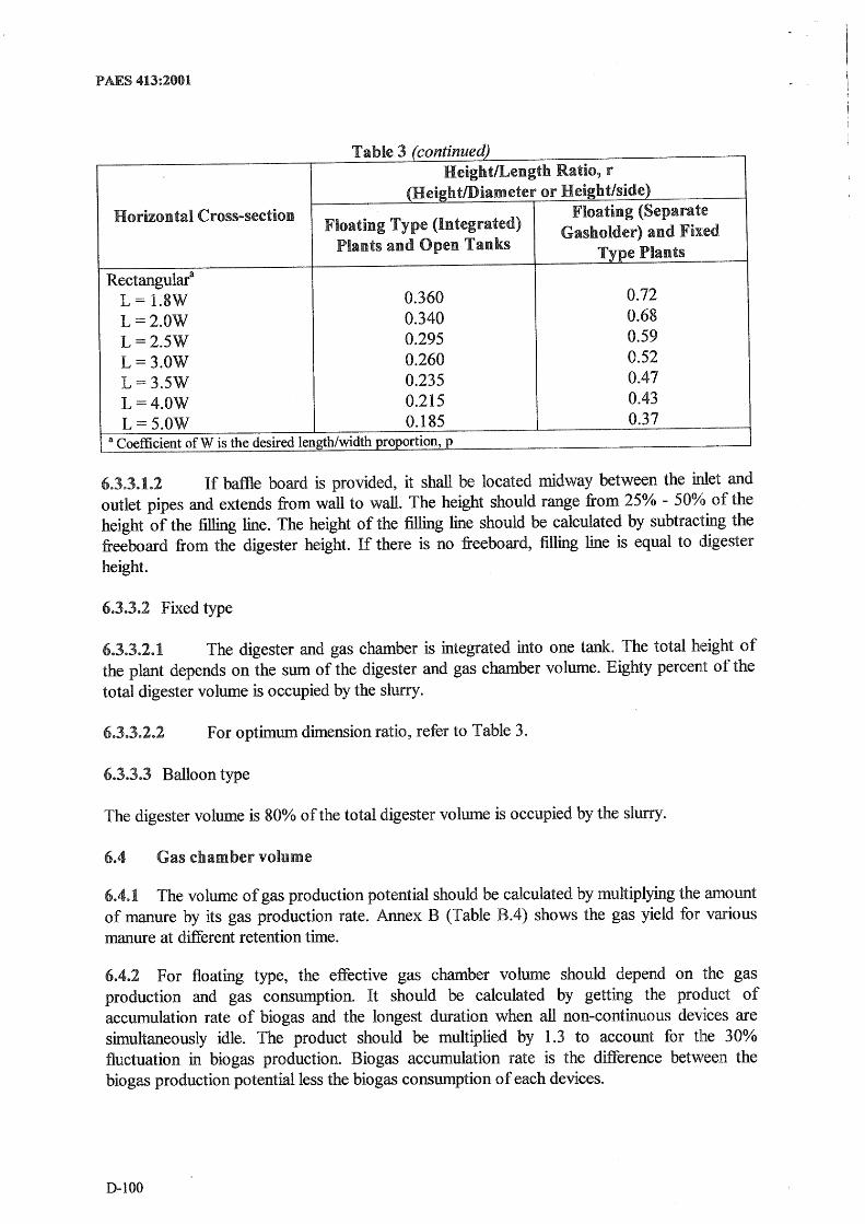
Table 3 (continued) HeightlLength Ratio, r
(Heigbt/Diameter or Height/side) Horizontal Cross-section Floating (Separate
Floating Type (Integrated) Gasholder) and Fixed Plants and Open Tanks Type Plants
Rectangulara
L = 1.8W 0.360 0.72 L=2.0W 0.340 0.68 L=2.5W 0.295 0.59 L=3.0W 0.260 0.52 L=3.SW 0.235 0.47 L=4.0W 0.215 0.43 L=5.0W 0.185 0.37 --
a Coefficient of W is the desired length/width proportion, p --
6.3.3.1.2 If baflle board is provided, it shall be located midway between the inlet and outlet pipes and extends from wall to wall. The height should range from 25% - 500/0 of the height of the filling line. The height of the filling line should be calculated by subtracting the freeboard from the digester height. If there is no freeboard, filling line is equal to digester height.
6.3.3.2 Fixed type
6.3.3.2.1 The digester and gas chamber is integrated into one tank. The total height of the plant depends on the sum of the digester and gas chamber volume. Eighty percent of the total digester volume is occupied by the slurry.
6.3.3.2.2 F or optimum dimension ratio, refer to Table 3.
6.3.3.3 Balloon type
The digester volume is 80% of the total digester volume is occupied by the slurry.
6.4 Gas chamber volume
6.4.1 The volume of gas production potential should be calculated by multiplying the amount of manure by its gas production rate. Annex B (Table BA) shows the gas yield for various manure at different retention time.
6.4.2 For floating type, the effective gas chamber volume should depend on the gas production and gas consumption. It should be calculated by getting the product of accumulation rate of biogas and the longest duration when all non-continuous devices are simultaneously idle. The product should be multiplied by 1.3 to account for the 30% fluctuation in biogas production. Biogas accumulation rate is the difference bet"veen the biogas production potential less the biogas conswnption of each devices.
D-IOO

PAES 413:2001
6.4.3 For fixed type and balloon type, about 20% of the total digester volume is occupied by the gas generated.
6.4.4 For cost minimization, effective gas volume should also be calculated by getting the daily biogas production less the daily biogas consumption.
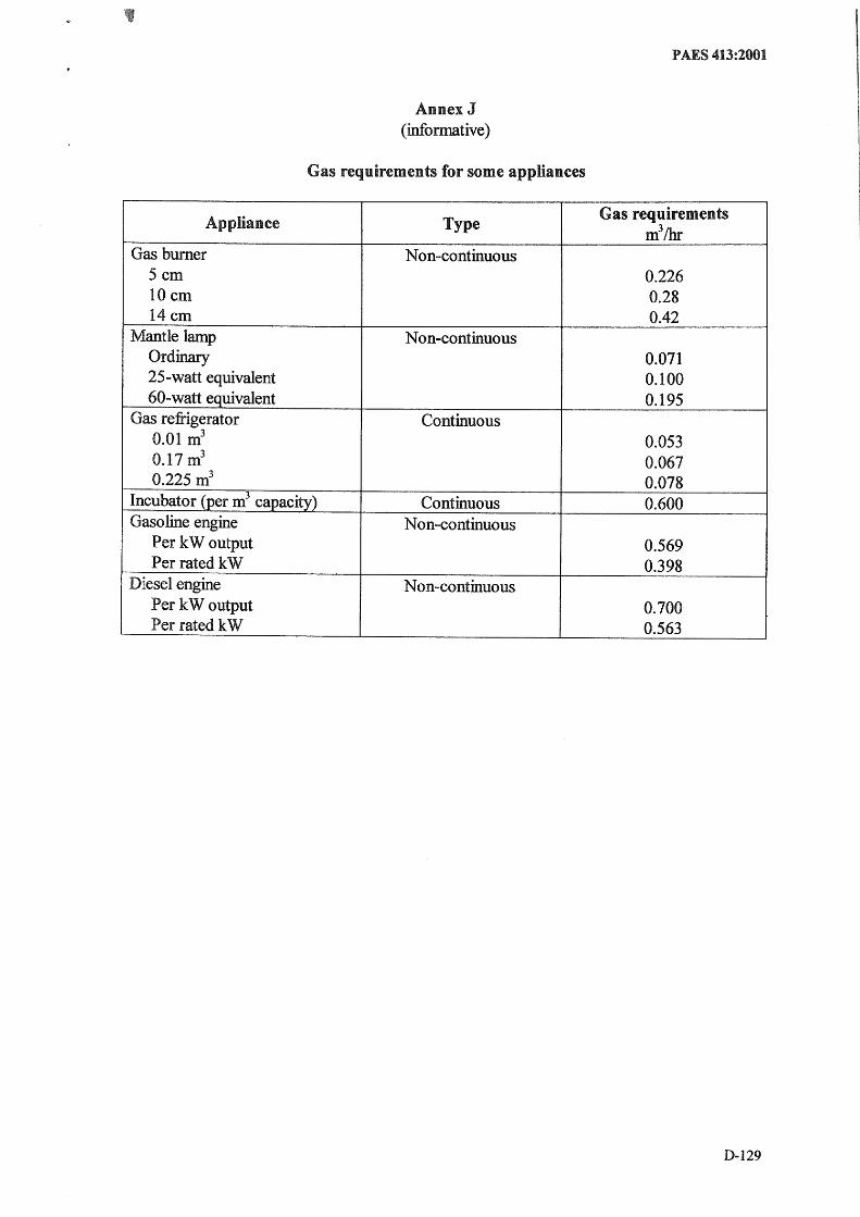
6.4.5 Annex J shows the type and biogas requirements of various appliances.
6.5 Outlet pipe
The minimum diameter of the outlet pipe shall be 0.2 m.
6.6 Outlet tank volume
6.6.1 For floating and balloon type, the minimum of volume of the outlet tank shall be equal to the daily slurry input of the digester.
6.6.2 For fixed type, the volume of the outlet tank shall be 1/3 of digester volume occupied by the slurry.
6.6.3 Calculation of optimum dimension should follow the same procedure used for digester tame
7 Functional requirement
7.1 Collecting tank
7.1.1 Concrete channels shall be provided from the source of substrate to the collecting tank with a l:ninimum slope of 2%.
7.1.2 The tank should be concreted and a sluice gate should be provided to control or allow the proper mixture of water and manure.
7.1.3 The floor of the mixing tank should be inclined from 8.5% - 17.5% toward the inlet pipe and it should be elevated at least 0.2 m from the filling line.
7.1.4 A cover made ofG.I. sheet shall be provided.
7.2 Inlet pipe
7.2.1 Concrete pipe (prefabricated RC pipe) should be used and it should be inclined 58% with digester wall.
7.2.2 Lower end of inlet pipe should be positioned below the gasholder retainer for floating type. If there is no retainer, the lower end should be located 100 rum from the floor of the digester.
D-lOl
PAES 413:2001
7.2.3 F or balloon type, the inlet pipe shall be directly connected to the plastic skin of the balloon. The pipe should be inserted to one half of its length in the interior of the plastk tube and the plastic tube shall be folded around it and shall be secured around the pipe.
7.2.4 The inlet pipe shall be sealed.
7.3 Digester
7.3.1 Fixed and Floating type
7.3.1.1 Digesters should be made of ferro cement , metal, adobe, bricks, reinforced concrete, or reinforced CHB.
7.3.1.2 For reinforced digester, reinforcement shall be a minimum of 10 mm diamett:r RSB spaced at 0.15 m (both the curved and the horizontal bars) and the curved bars shall be anchored at the top beam. All reinforcement bars shall be secured and tied together with GI wire.
7.3.1.3 More steel reinforcements shall be used for larger digester volume.
7.3 .. 1.4 The concrete walls of the digester shall be reinforced with G.I. chicken wir,e mesh before plastering with class A mortar mixed with sealing compound or water-proofing compound. Plaster shall be applied in three layers (13 mm, 6 mm, and 6 mm thick). Ea(~h layer shall be applied continuously and should be finished within one day. All comers of the digester shall be curved.
7.3.1.5 Floors, beams and foundation shall withstand the maximum load and shall be made of reinforced concrete.
7.3.1.6 Access to the digester should be through the manhole or through the: outlet chamber. If a manhole is used as the access inside the digester, it should be constructed in the center of the dome and it should be tightly sealed. Manhole cover should be 0.65 m in diameter and 0.125 m thick.
7.3.2 Balloon type
7.3.2.1 A trench should be dug out from the ground to protect the digester from any damage (from wild and domestic animals) and to help to maintain an appropriate environment for the production of biogas.
7.3.2 .. 2 The sides and floor of the trench should be smooth with no protruding stones or roots, which could damage the plastic film.
7.3.2.3 The floor shall have a slope of about 2.5% from the inlet to the outlet
7.3.2.4 Balloon should is made of red mud plastic, natural polyethylene plastic tube, heatsealed plastic or rubber balloon where the upper portion serves as the gas storage. In setting the balloon digester, it should be made of two layers of snugly fitted plastic.
D-I02

PAES 413:2001
7.352.5 The plastic tube shall be at least 200 microns.
7.4 Agitator/Stirrer
7.4.1 Natural agitation is recommended for small, low-cost and simple biogas plant.
704.1.1 The continuous feeding of a hiogas plant can impart motion to the rest of the slurry (Figure 1).
Figure 1 - Mixing substrate through inherent flow in fixed-dome plants
7.4 .. 1.2 Other kind of agitation occur as biogas is formed in the sludge layer at the bottom layer, the gas forces the sludge particles to rise to the surface, where they are released and the then particles will fall back to the sludge layer.
7.4.1.3 Natural agitation occurs when the sludge is heated. The hotter slurry will tend to rise within the body of the cooler slurry.
7.4.2 Mechanical agitation should be provided for larger biogas, floating and balloon plants several times a day to:
III to avoid and destroy swimming and sinking layers, III to improve the activity of bacteria trough release of biogas and provision of fresh
nutrients, II to mix fresh and fermenting substrate in order to inoculate the former, and i! to arrive at an even distribution of temperature thus providing uniform conditions
inside the digester.
7.4L2Jl Agitation. should be performed as much as necessary but as little as possible. Annex F shows the various methods of mixing the substrate.
7.5 Gas chamber
7.5.1 Floating-drum plant
7 .. 5 .. 1..1 The gas drum should consist of2.5 mm mild steel sheets for the sides and 2 mm sheets for the top. It should have a welded-in brace, which break up the surface scum. The drum should be protected against corrosion with suitable coating (oil paints, synthetic paints and bitumen paints).
D-I03

PAES 413:2001
7.S.L2 If the floating-drum is made of 20 mm wire mesh-reinforced concrete or fiber ce:ment, it shall have gas-tight internal coating. PVC drums should not be used.
705.1.3 The gas drum should have a sloping roof (16.5% slope) and it should be provided with guide frame.
7.S.L4 The sidewall of the gas drum shall be as high as the wall above the support ledge. Guide frame shall be provided to prevent the floating drum to come into contact with the outer wall and to allow the gas drum to be removed for repair.
7.5.1.5 The depth of liquid jacket should be about 95% of the height of the gasholder and it shall not be less than 300 mm.
7.S.L6 If the gasholder is too light or too heavy to maintain the desired gas pre:ssure, external weight shall be provided.
705.1. 7 U-tube manometer should be provided to indicate the relative amount of gas in storage within the biogas plant.
7.5.2 Fixed dome plant
7.5,,2.1 The concrete dome shall be reinforced with screen before plastering with class A mortar mixed with sealing compound. Plaster shall be applied in three layers (13 mm, 6 ~ and 6 mm thick). It should be applied continuously and should be :finished within one day.
7.5.2.2 T~e gas chamber shall be capable of withstanding an internal pressure of 0.15 bar.
7.5.2.3 The top part of a fixed-dome plant shall be painted with a gas-tight layer (,water proofer', latex or synthetic paints).
7.5.2.4 A weak-ring in the masonry of the digester should be provided to reduce the risk of cracking of the gas chamber. This should be placed between the lower (water-proof) aLnd the upper (gas-proof) part of the hemispherical structure.
7.6 Gas Outlet pipe
7.6 .. 1 Gas outlet pipe shall be provided and it shall be connected to outgoing biogas valve. Ball valves or cock valves should be used. It should also be installed at all gas appliances as shutoff devices.
7.6.2 Sealed T -joints should be connected before and after the main valve to tlest the digester and the piping system for their gas-tightness separately.
7.6.3 Gas escape valve prepared from three pieces of PVC pipes should be providt~d, one arm of the T -joint is connected from the gas outlet and the other arm links to the pipe which goes to the kitchen. The T -joint is inserted in the bottle and water is added to a dt~pth of 40mm - 50 mm above the lower point of the T. Sides of the bottle should punched with small holes with a height equal to the desired level of pressure to be maintained.
D-I04

PAES 413:2001
7Ji.4 Piping system connects the biogas plant to the gas appliances or to the gas reservoir. Gas rreservoir should be made of plastic or steel.
706~5 Piping system should be made ofG.I. pipes or PVC pipes.
7~6.6 PVC pipes are susceptible to UV radiation and can easily be damaged; hence, PVC pipes should be placed underground. If the site is located in an area with high intensity of sunlight, 0.1. pipe should be used.
706.7 PVC should be laid at least 0.25 m deep underground. It should be placed in a sand bed and be covered with sand or fine earth.
7.6 .. 8 Table 4, shows the recommended pipe diameters depending on the flow-rate ofbiogas through the pipe and the distance between biogas digester and gas appliances.
Table 4 - Pipe OI~lmf~H::r' pipe lengths and flow-rate (maximum pressure loss <5 mbar)
Galvanized steel pipe PVC mm mm
Length m 20 60 100 20 60 100
Flow-rate m 3/h 0.1 12.7 12.7 12.7 12.7 12.7 12.7 --0.2 12.7 12.7 12.7 12.7 12.7 12.7 0.3 12.7 12.7 12.7 12.7 12.7 12.7 0.4 12.7 12.7 12.7 12.7 12.7 12.7 O.S 12.7 12.7 19.0 12.7 12.7 12.7 1.0 19.0 19.0 19.0 12.7 19.0 19.0 1.S 19.0 19.0 2S.4 12.7 19.0 19.0
1--- _ .. _-----2.0 19.0 2S.4 2S.4 19.0 19.0 2S.4 -- --~"-
7,.6/~ If there are turns and bends in the piping system and used for indoors, heavy-duty hose with ply should be used. The minimum diameter should be 13 rom and if used in outdoor, it should be protected from high sunlight exposure.
7.6.10 Piping system should be laid out in a way that allows a free flow of condensation water from moisture-saturated biogas back into the digester.
7.6.11 If depressions in the piping system cannot be avoided, water traps shall be installed at the lowest point of depressions with a minimum inclination of 1 %.
7 .. 6.12 Flame arrester shall be provided. It should be made ofa ball or roll of fine copper wire mesh inserted in the gas line and it should be located near the digester and near to the point of gas use.
7.7 Outlet pipe
707,.1 Concrete pipe (prefabricated RC pipe) should be used with a minimum diameter of 200 rnm and it should be inclined 58% with digester wall.
7.7.2 For the fixed type, the upper end of the outlet pipe should be level with the bottom of the auxiliary chamber to allow the drawing back of slurry when the pressure decreases.
D-IOS
PAES 413:2001
7.7.3 For balloon type, the outlet pipe shall be directly connected to the plastic skin of the balloon. The pipe should be inserted to one half of its length in the interior of the plasti(~ tube and the plastic tube should be folded around it and should be secured around the pipe.
7.7.4 For the floating type, the upper end of the outlet should be elevated from the floor of the sludge tank.
7.7.5 The outlet pipe shall be sealed.
7.8 Outlet tank
7.8.1 The chamber should be made of concrete with smooth finish. Steel reinforcement may be used.
7.8.2 The chamber shall be provided with a cover made of ordinary or corrugated GI sheets.
7.8.3 Overflow should be provided with the height of at least 100 mm lower than the lower surface of the gas chamber. It should flow into farmland of the plant owner or flow into the lagoon for further treatment.
7.8.4 The height of the floor of the chamber from the filling line shall be at least equal to the operating pressure for appliances using biogas or the height should be at least 0.2 m from the filling line plus 15% freeboard.
7.9 Ground water drainage
7.9.1 If the water seeps from bottom of the excavated pit, blind drain shall be constructed. It should be filled with gravels or chip of tiles, with central sump and take water away manually or by pump.
7.9.2 Ifwater seeps from wall of the excavated earth bank, circular drain outside the location of digester wall shall be constructed to lead water away to sump or some lower places.
7.9.3 In case groundwater is in great quantity, deep wells should be constructed 2 m away from the excavated pit, with a depth 0.8 m - 0.1 m lower than the pit, then pump water away from wells.
7.9.4 In case of too much water and shifting sand sunken barrel shall be used.
7.10 Facilities of a biogas plant
7.10.1 Heating systems
7.10.1.1 If the temperature of the substrate is below the proper process temperature, heating system is recommended.
7.10.1.2 Heating should either be direct heating in the form of mixing hot water to the slurry or indirect heating using heat exchanger located either inside or outside the digester.
D-I06

PAES 413:2001
7.10.2 Pumps
7.10.2.1 If the amount of substrate requires fast movement, to mix the substrate and when the gravity cannot be used for reasons of topography or substrate characteristics, use of pumps is recommended.
7.10.2.2 Centrifugal pumps for liquid substrate or rotary pumps for substrate of less than 8% solid content or positive displacement pumps for substrate with higher solid content may be used.
7.10.2.3 Pump delivery lines should be made of steel, PVC (rigid), PE (rigid or flexible), or flexible pressure tubing made of reinforced plastic or rubber.
8 Safety considerations
8.1 Visual check
Cracks, gap and tightness of duct in the digester inner wall should be carefully checked using wooden hammer. If vacant sound was heard in a certain area, there is some warping in plastering. Leak trace for wall should be check by spreading some cement powder over the surfac,e, the wet spot or wet line proves that there is leak hole or leak crack.
8.2 Water-holding mark
The digester should be filled with water up to the inlet and outlet pipes level. Allow it to set for 3-5 hours until the walls are saturated with water and mark the water level. Set it for overnight, if there is significant drop in water leve~ it indicates that there are leaks or cracks.
8.3 Air tight method
After 'water tightness test, gas test should be followed. Manhole and gas valves should closed and se:aled. Add water through the inlet to increase the air pressure inside the digester up to 0.4m of water column. Or air may be blown into the digester up to the same pressure. Leave it for 24 hours, if the pressure drop is about 10 mm - 20 mm, the digester is gas tight. But if the pressure drop is about 50 mm, the dome is not gas tight.
9 Sludge management
9.1 The digested slurry should be either spread on the fields before the beginning of the vegetation period or further conditioned.
9.2 The sludge should be channeled to a sludge conditioning facilities where the solid component is separated and sun-dried while the liquid part is aerated to oxidize the toxic component. For the detailed effluent handling of biogas plant, refer to PAES 414:2002 Agricultural Structures - Waste Management Structures.
1)..107

PAES 413:2001
r-..n,u,...,Rc A (infonnative)
Digestion process
Stage 1 - Hydrolysis
The waste materials of plant and animals origins, which consist mainly of carbohydrates, lipids, proteins, and inorganic materials are solubilized into simpler ones with t]:l(:: help of extracellular enzyme released by the bacteria.
Stage 2 - Acidification
The monomer such as glucose, which is produced in Stage 1, is fermented under anaerobic condition into various acids with the help of enzymes produced by the acid forming bacteria. At this stage, the acid-forming bacteria break down molecules of six atoms of carbon into molecules of less atoms of carbon which are in more reduced state. The principal acids produced in this process are acetic acid, propionic acid, butyric acid and ethanol.
Stage 3 - Methanization
The principal acids produce in stage 2 are processed by methanogenic bacteria to produce methane.
CH3COOH ~ C~ + CO2
Acetic acid Methane Carbon dioxide
2CH3CH20H + CO2 ~ C~ + 2CH3COOH Ethanol Carbon dioxide Methane Acetic acid
CO2 +4H2 ~ C& + 2H2O Carbon dioxide Hydrogen Methane Water
D-I08

Bol Temperatu.re
Annex B (informative)
Digestion process parameters optimization
PAES 413:2001
For anaerobic fermentation, mesophilic temperature range should be 20°C - 40°C, with temperature fluctuations of ± l°CIh.
B.l pH value The lPH value should normally take on a value between 7 - 8.5, ifpH value drops below 6.2, the nledium will have a toxic effect on the methanogenic bacteria.
D.3 Available Nutrient Substrates should contain adequate amount of carbon, oxygen, hydrogen, nitrogen,. sulfur, phosphorous, potassium, calcium, magnesium and a number of trace elements (Table B.I).
Table B.I - Nu.trient content of common animal excrements
. ,,---_.
Animal -.. -~~-
1 Co", Pig Chi( Chi(
--~----
~ken (fresh dro~~ings) ~ken (dry droppings)
Inhibitory factors
L.-.
PzOs kg/a % kg/a 34 0.2 84 56 0.4 35 194 1.0 108 193 4.6 106
KzO ---.-.. -.--6/0 -0.5 ---0.3 -. 0.6 2.5
Small quantity of mineral ions stimulates the growth of bacteria, while heavy concentration of these ions will have toxic effect. Table B.2 shows the limit concentrations for various inhibitors.
Table - Limiting concentrations for various inhibitors of biomethanization _. ._-- .--~.
Substance Concentration
mg/I -- -_ .... _.-
~~~! 10 - 250 ----.-
Caleium 8000 --Sodium 8000 --
JVlagnesium 3000 Nickel 100 - 1000 --Zine 350 -1000 -- ._--- .. ""~--.---
Chromium 200 -2000 ,....- . .----.-.... ~-.~
Sulfide (as sulfur) 200 -- .-
Cyanide 2
D-I09

P AES 413:2001
B.S Nitrogen content and CIN ratio
B.S.I For anaerobic digestion of organic materials, a carbon/nitrogen ratio should be 'within the range of 1 :20 - 1 :30. The e/N ration should not be more than 1 :35.
B.S.2 Materials with high C/N ratio should be mixed be mixed with those of low C/N ratio to bring the average ratio of the composite input to a desirable level. Table B.3 shows the value of CIN ration for different biodegradable material.
Table B.3 - elN ratio and nitrogen content of some organic materials
Biodegradable material N C/N %
A. Animal dung - Hog 2.8 13.7 - Carabao 1.6 23.1
- Cow 1.8 19.9
- Chicken 3.7 9.65 - Duck 0.8 27.4 - Pugo 5.0 6.74
B. Household waste - Nightsoil 7.1 6.72 - Kitchen waste 1.9 28.60
C. Crop residues (air-dry) - Com stalks 1.2 56.6 - Rice straw 0.7 51.0 - Corncobs 1.0 49.9 - Peanut hulls 1.7 31.0 - Cogon 1.07 -- Bagasse 0.40 -
D. Others - Kangkong 4.3 7.8 - Water lily 2.9 11.4 - Grass trimmings 2.5 15.7
B.6 Gas production potential
Table B.4 -Gas production potential of various types of manure in m3/kg
Manure
2S Pig 0.058 Cow 0.030 Buffalo 0.030 Horse 0.045 Chicken 0.060
0-110
Retention Period days
30 3S 0.063 0.068 0.034 0.037 0.034 0.037 0.051 0.056 0.065 0.069
SO 0.01' 7
3 3 5 8
0.04. 0.04: 0.06: 0.07
Annex C (infonnative)
Excavation and backfilling
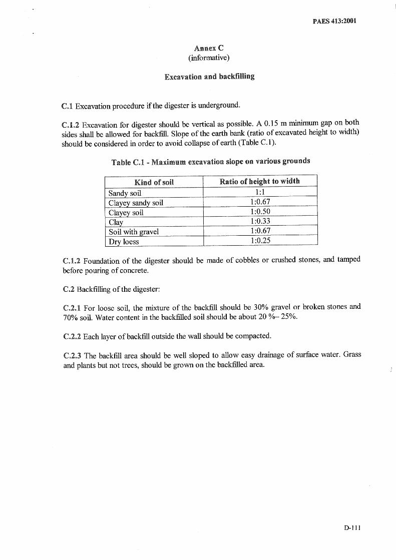
C.1 Excavation procedure if the digester is underground.
PAES 413:2001
C.1.2 Excavation for digester should be vertical as possible. A 0.15 m minimum gap on both sides shall be allowed for backfill. Slope of the earth bank (ratio of excavated height to width) should be considered in order to avoid collapse of earth (Table C.1).
Table C.1 - Maximum excavation slope on various grounds
Kind of soil Ratio of height to width
Sandy soil 1:1 Clayey sandy soil 1:0.67 Clayey soil 1:0.50
-Clay 1:0.33 Soil with gravel 1:0.67 Dry loess 1:0.25
C.l.2 Foundation of the digester should be made of cobbles or crushed stones, and tamped before pouring of concrete.
C.2 Backfilling of the digester:
C.2.1 For loose soil, the mixture of the backfill should be 30% gravel or broken stones and 70CX, soil. Water content in the backfilled soil should be about 20 0/0- 25%.
C.2.2 Each layer of backfill outside the wall should be compacted.
C.2..3 The backfill area should be well sloped to allow easy drainage of surface water. Grass and plants but not trees, should be grown on the backfilled area.
D-Ill

PAlES 413:2001
(informative)
Parts of biogas plant
Parts of Floating type plant with external guide frame: 1. Collecting pit, 2. Digester, 3. Gas chamber, 4. Slurry store, 5. Gas pipe, 6. Fill pipe, 7. Guide frame
(7)
r~----------=-' CD
Pruis of Fixed type plant: 1. Collecting tank with inlet pipe and sand trap, 2. Digester, 3. C0111pensation and rernoval tank, 4. Gas chamber, 5. Gaspipe, 6. Entry hatch, with gas tight seal, 7. Accumulation of thick sludge, 8. Outlet pipe, 9. Reference level, and 10. Supernatant scum, broken up by varying leveL
D~112

PAES 413:2001
D.:~ Parts of Balloon type plant: 1. Inlet, 2. gas pipe, 3. Gas chamber, 4. Slurry volume and 5. Outlet pipe
CD
@) ';(" ------------------------------''i~. _ __ ___ ____ __ ___ _ __ _ __ _ :::::/
~ ~ ~,~, -:;(,- ~y_:;-0'_:;:;;,; ';.--:-;:;:; ~-:;-;--:;-, -0'-, '77'i/ - - v:~y.
"<'{«i:«i:'-««k«:1..«~<M~«@::«i..'Y.:«:&«k«i..«<<<k~<<:~<f0K&k.!k~~~<<~K<<<<<:~P
D-1l3

PAES 413:2001
AnnexE (informative)
Formula used in calculating the dimensions (with 15% freeboard)
E.l Digester
E.1.1 Floating type
E.1.Ll Cylindrical digester
" ~.6XVd Inner dIameter, D d = 3 1r X r
Digester Height = rDd
where: V d = effective digester volume, m3
r = height/diameter ratio
E.1.1.2 Square digester
"d h d" S V1.15 XVd Inner SI e of t e square Igester, d = 3 r
Digester Height = rSd
where: V d = effective digester vo lume, m3
r = height/diameter ratio
E.l.L3 Rectangular digester
0-114
I :dth f 1 d" W 1.15xVd nner WI 0 rectangu ar Igester, d = 3 2 rxp
Digester Height = rLd
where: V d = effective digester volume, m3
r = height/diameter ratio p = desired width and length proportion

E.l.2 Fixed type
E.1.2.1 Cylindrical digester
~4r'V Total height, m=1.2 3 --;;-
where: V d = effective digester volume, m3
r = height/diameter ratio
E.1.2.2 Square digester
Total height = 1.2 Vr2 Vd
where: Vd = effective digester volume, m3
r = height/diameter ratio
E.l.2.3 Rectangular digester
Total height = 1.2 Vpr2 Vg
vv"here: Vd = effective digester volume, nl r = height/diameter ratio p = desired width and length proportion
Ee2 (;as chamber (Floating type)
Ee2.I Cylindrical gas chamber
Inner diameter ofgaschamber,Dg (m) 45x Dd -w
50
D xtan9.5° height of pyramidalroof,h (m) -g----2
height of gas chamber, Hg (m) = 1.1S( 4Vg 2 + Hp) 1l" Dg
where: Dd = inner diameter of digester, m V g = effective gas chamber volume, m3
Hp = desired pressure head, m w = gas chamber wall thickness, cm
PAES 413:2001
D-1l5

PAES 413:2001
E.2.2 SquarelRectangular gas chamber
45x L -w Inner length of gaschamber,Lg (m) = d
50
Inner width of gas chamber, Wg(m) 45x Wd -w
50
W xtan9.5° height of pyramidalroof,h (m) ---,,-g---
2
height of gas chamber wall,Hg (m) = l.ll Vg +HpJ l LgWg
where: Ld = inner length of rectangular digester, m
Wd = inner width of rectangular digester, m
Hp = desired pressure head, m
w = gas chamber wall thickness, cm
NOTE If the gas chamer is made of steel sheets, wall thickness is insignificant
NOTE 2 Lg = W g and W g = Sg for square cross-section
E.2.3 Water-sealed gas chamber (upper part of the digester is double-walled)
55x Ld +t Innerlength ofgaschamber,Lg (m) 50
55x W +t Inner width of gas chamber, W g (m) = d
50
. 55x Dd +t Inner dlameter of gas chamber, Dg (m) =--5-0-'----
where: Ld = inner length of rectangular digester, m
Wd = inner width of rectangular digester, m
Dd = inner diameter of digester, m
t = digester wall thickness, em
E.2.4 Distance of retainer
Distance of the retainer below the top of the digester wall
D-116
= 0.13 x ht. of digester + O.87( ht. of gasholder - desired pressure head)
P AES 413:2001
Annex F (informative)
Sample calculation for the design and utilization of floating-drum plant
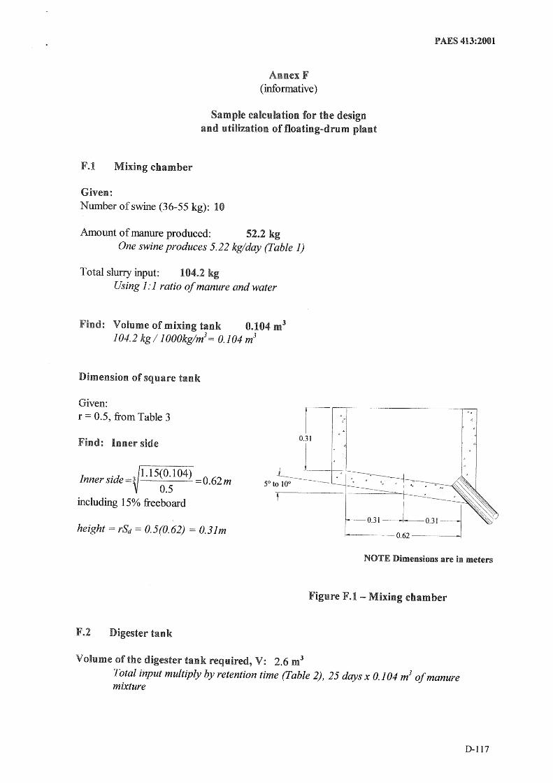
F.l Mixing chamber
Given: Number of swine (36-55 kg): 10
Alnount of manure produced: 52.2 kg One swine produces 5.22 kg/day (fable 1)
Total slurry input: 104.2 kg Using 1: 1 ratio of manure and water
Find: Volume of mixing tank 0.104 m3
104.2 kg / 1 000kg/m3 = 0.104 m3
Dimension of square tank
Given: r =: 0.5, from Table 3
Find: Inner side
Inner side =3 1.15(0.104)_=0.62m 0.5
including 15% freeboard
height = rSd = 0.5(0.62) = 0.31m
r- ,
~---- 0.62 --_ ... _.---
NOTE Dimensions are in meters
Figure F.1 - Mixing chamber
F.2 Digester tank
Volume of the digester tank required, V: 2.6 m3
Total input multiply by retention time (fable 2),25 days x 0.104 m3 of manure mixture
D-1l7

P AES 413:2001
Dimension of rectangular digestion tank:
Given: r = 0.455 L = 1.2\\1
Find: Dimension of Digester
Width,W=3 1.15x2.62
=1.66m 0.455 xl.2
L = 1. 2W = 1.2 x 1.66 = 2 m
H = rL = 0.455(2) = 0.91 m
Find: Height of the bame board, minimum
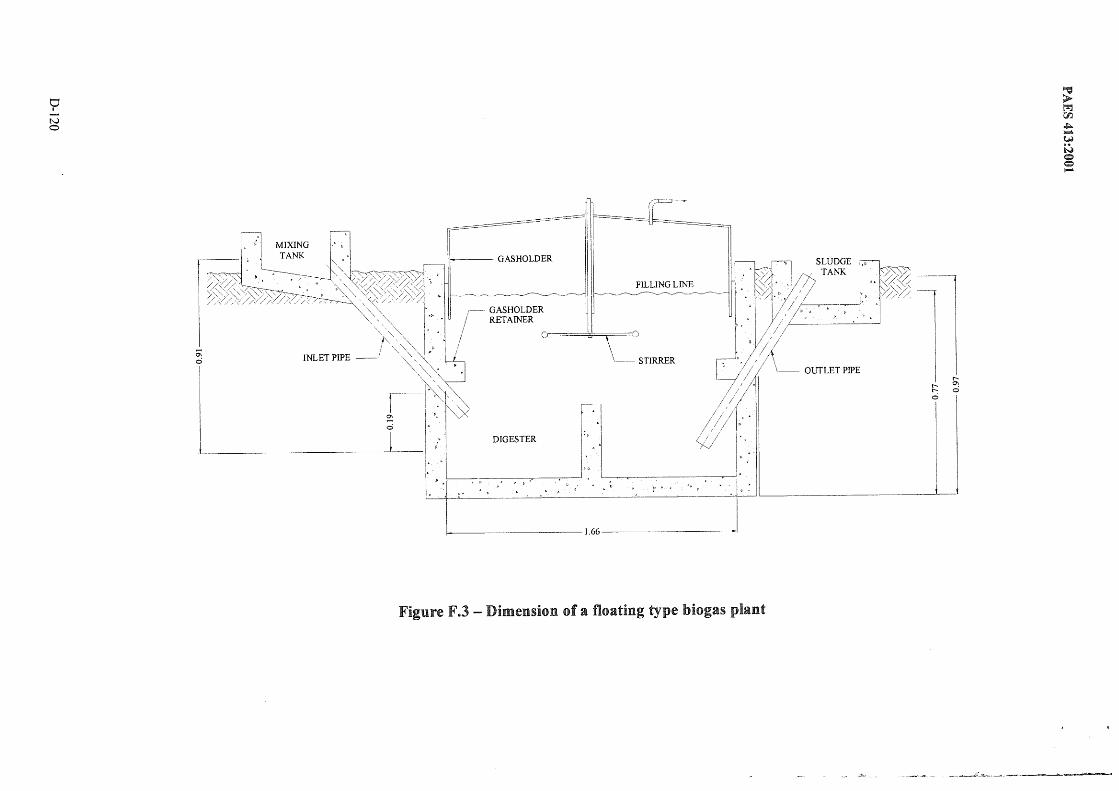
filling line = height of the digester -freeboard = 0.91 (1-.15) = 0.77 m
(25-50% of the filling line) = 0.77 x 0.25 =0.19 m
F.3 Gasholder
Given: 52.2 kg manure 1 kg manure produces 0.058 m3 (Annex B, Table B.4) for 25 days retention time volume of gas/day = 52.2 x 0.058 = 3.5 m3
Assume: Biogas utilization for one day (Annex J) Light (ordinary)
2 light x 3 hr x 0.071 m31hr = 0.426m31day Stove (5 em)
1 stove x 3 hr x 0.226 m3/hr = 0.678m3/day Refrigerator (0.01 m3)
1 ref x 24 hr x 0.053 m31hr = 1.272m3/dav roTM 23mm~~
Gas to be stored: 3.5 - 2.376 = 1.124 m3 x 130% for biogas fluctuation = 1.46 m3
Volume of gas = 1.46 m3
Find: Dimension of gashoider Assume the desired pressure head to be maintained within the gasholder is 20 cm
Length of gasholder = 45 x 3.2/50 = 2.88 m
D-118

PAES 413:2001
Width of gasholder = 45 x 2.7/50 = 2.43 m
Height of gasholder wall = 1.15 [1.46/(1.8 x 1.44) + 0.2] = 0.88 m
Height of gasholder roof= (1.44 x tan 9.5)/2 = 0.12 m
Length of gas retainer ( 11% of inner digester length) = 0.11 x 2 =0.22 m
distance of the retainer below the top o/the = 0.13x 0.91 + 0.87(0.88 - 0.2) = 0.71 m digester wall
1-------------1.66 ----------;
·---1.44----------;
GASHOLDER
I ~-
STIRRER
Figure F.2 - Floating drum gasholder
F.4 Outlet chamber
DiBnensions are the same as the inlet chamber
Location of pipes
0.11
00 00 ci
upper inlet pipe should be 20 em above the filling line or 0.97 m from the digester floor and the lower is located below the gas retainer
upper end should be 20 em above the filling line and the lower end of the pipe should be 10 em above the floor
D-119
o I
N o
f-------------1.66-------------'
Figure F.3 - Dimension of a floating type hiogas plant
_ . .,.~.:x",- .. ...-.._
~ > tr.I 'CI'1 ~ J-I. W N c:::> e .....
Sludge overflow
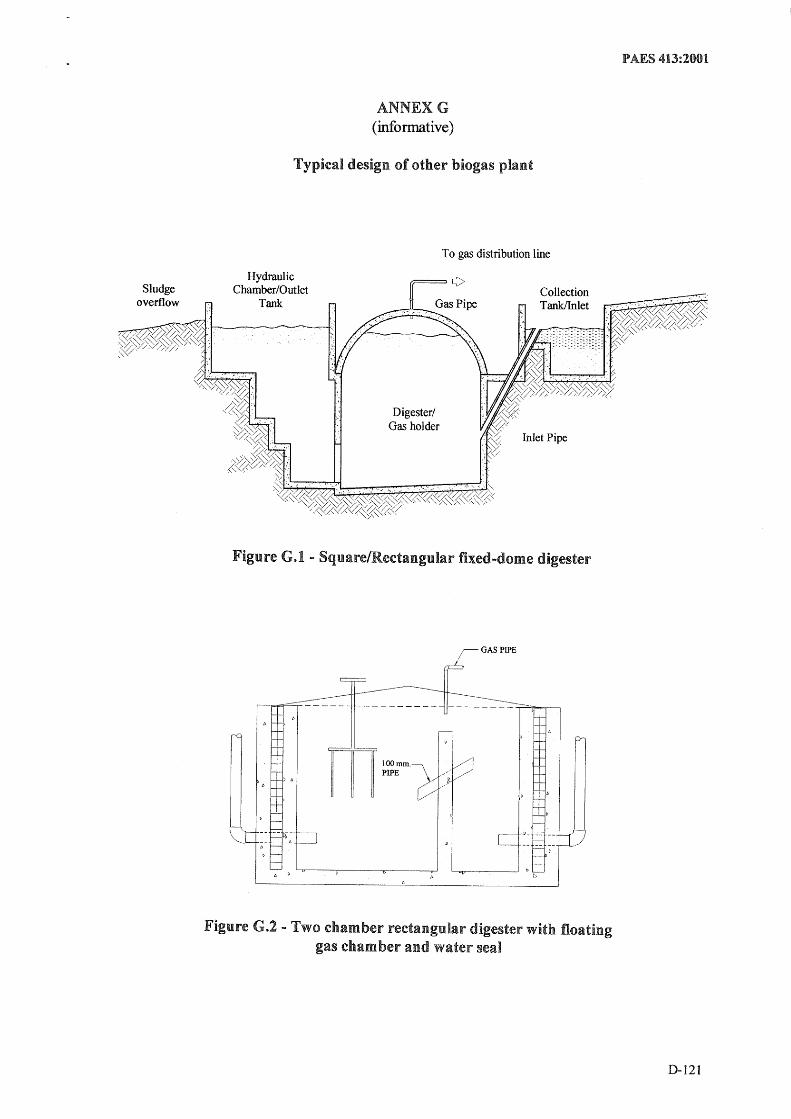
ANNEXG (informative)
Typical design of other biogas plant
Hydraulic Chamber/Outlet
Tank
Digester/ Gas holder
To gas distribution line
Figure G.I .. SquarelRectangular fixed-dome digester
iGASPIPE
--------- --------~~~
lOOmm. PIPE
Figure G.2 - Two chamber rectangular digester with floating gas cham ber and water seal
PAES 413:2001
D-121

P AES 413:2001
Figure G.3 - Two chamber rectangular digester with floating gas chamber
Waste
D-122
Biogas Gas collector, fixed dome
---- Slurry
-- Automatic overflow
Sludge outlet
Figure GA - Fixed dome plant CAMARTEC design
Figure G.5- Fixed dome plant Deenbandhu design

P AES 413:2001
Gas
- ~ . .---- - - - -.~ _.- -.- - - - -.- -
--------------
Figure G.6 - Square fixed dome digester
c li ~ Inlet
/~, ni'/ ~~ Floater ~, .. '- _ ~as __
-- - - "~\, '~~ ~~z;:n::r:rr::r::r:rr:rr:rr:rJJ -Water--"" - - - - - --
- =Sluny-.-
Figure G.7 - Fixed Dome digester with separate gas chamber
0-123
P AES 413:2001
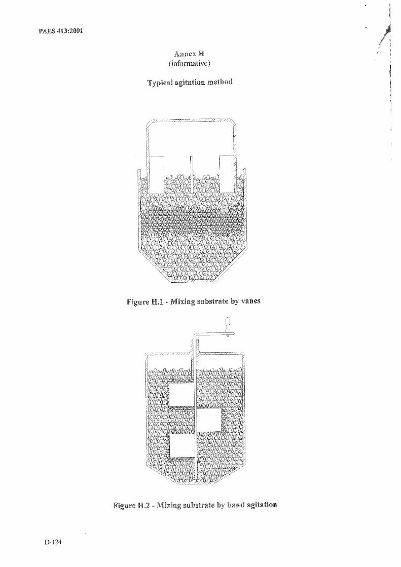
(infonnative)
vanes
agitation
D-124

PAES 413:2001
Figure
D-125

PAES 413:2001
/~Va1ve
Figure H.S - Mixing substrate by modified gas .. powered agitation
Gas Pressure ___ ~
Figure H.6 - Mixing substrate by bubble pump
D-126
1.1 Initial loading
1.1.1 Starter/Seeding
Annex I (informative)
Operation and maintenance
PAES 413:2001
The initial raw materials should contain slurry with a high bacteria population. About 5-10% of the total slurry volume should be added when the digester is about 250/0 full.
I.L2 Filling the digester
Before putting any slurry into digester. All valves should be open. Mix the manure and water thoroughly and fill the digester up to the ring level or top beam. Do not add any new slurry to the digester until at least three days after combustible gas is produced.
1.2 Mixing slurry for regu.lar loading
About one liter of water should be added to every kilo of manure and it should be thoroughly mixedt until the right consistency is obtained.
1.3 Regu.lar loading of input materials and removal of emuent from outlet chamber
The loading of materials should be done regularly. The amount of slurry to be loaded should be in accordance with the requirement of the particular digester volume and its retention time. The loading of new slurry displaced an equal volume of eflluent to the outlet chamber which should be removed.
1.4 Stirring/Agitation
If stirring is necessary, it should be done daily: three minutes in the morning and three minutes in the afternoon. The stirring should be 360 degrees in one direction, then 360 degrees in the opposite direction.
I.~~ Servicing scum
AU gas within the digester should be released and the gas piping closest to the digester should be: disconnected.
1.7 Periodic cleaning of the digester
The dligester should be emptied at intervals to remove the settled sludge and other inorganic solids that accumulate at the bottom of the digester.
D-127
PAES 413:2001
1.8 Repairing masonry work within. the digester
If the digester is damaged in the form of cracks or leaks, the damaged area should be repaired. The edges of the damaged area should be cleaned and roughened. Two to three layers of chicken wire should be attached to the walls with nails at least 30 cm from either side of the crack. The plastering cement-sand (l :3) mortar should be at least 13 mm thick. The finish should be roughened and should be allowed to dry for at least two weeks. Wax/paraffin seal should be applied.
1.9 Entering the digester
When entering a digester which has been used, the manhole should be removed for several days and gas line closest to the digester should be disconnected. The contents shoulld be removed and the tank should be ventilated. Before entering, presence of harmful gasses or sufficient air should be first checked. Flames should be avoided near or within the digester .. A .. piece of pipe or hose through which the worker inside the pit may breath should be provided. Another person should be constantly watching from the outside of the pit that can respond to any emergency.
D-128
--Appliance
f---
Gas burner 5em 10 cm 14cm
f---
Mantle lamp Ordinary 25-watt equivalent
-- 60-watt equivalent Gas refrigerator
0.01 m3
0.17 m3
0.225 m3 --
Annex J (informative)
Gas requirements for some appliances
Type
Non-continuous
Non-continuous
Continuous
Incubator (per m3 capacity) Continuous --Gasoline engine Non-continuous
Per kW output Per rated kW
Diesel engine Non-continuous Per kW output Per rated kW
P AES 413:2001
Gas requirements m3/hr
0.226 0.28 0.42
0.071 0.100 0.195
0.053 0.067 0.078 0.600
0.569 0.398
0.700 0.563
D-129

... P ..... H ..... I ...... L-Ip ...... P ...... I ...... N ...... E ...... A ..... G ..... ru ........... C ..... U ..... L ..... TU ..... RA ........... L-E ...... N ...... G ...... IN ..... E ...... E ...... R ...... I ...... N"""":G~S~T ...... A~N~D~A~RD~-~P~A~E~S~4~1"'='5:~2~Ooi
Agricultural Structures - Greenhouses
Foreword
The formulation 0 f this national standard was initiated by the Agricultural Machinery Testing
and Evaluation Center (AMTEC) under the project entitled "Enhancing the Implementation
of the AFMA Through Improved Agricultural Engineering Standards" which was funded by
the Bureau of Agricultural Research (BAR) of the Department of Agriculture (DA).
This standard has been technically prepared in accordance with PNS 01-4:1998 (ISOIIEC
Directives Part 3: 1997 - Rules for the Structure and Drafting of International Standards. It
specifies the general requirements for greenhouse.
The word "shall" is used to indicate requirements strictly to be followed in order to conform
to the standard and from which no deviation is permitted.
The word "should" is used to indicate that among several possibilities one is recommended as
particularly suitable, without mentioning or excluding others, or that a certain course of
action is preferred but not necessarily required.
In the formulation of this standard reference were made to:
ASAE EP 406 ASAE Engineering Practice, Heating, Ventilating and Cooling Greenhouses.
ASAE Standards 1987.
Nuess, Mike. Designing and Building a Solar Greenhouse or Sunspace. Washington. 1997
OSU Extension Facts F-6700. Greenhouse Structures and Coverings. Oklahoma Cooperative
Extension Service. Division of Agricultural Sciences and Natural Resources.
OSU Extension Facts F-6700. Greenhouse Floors and Benches. Oklahoma Cooperative
Extension Service. Division of Agricultural Sciences and Natural Resources.
Ross S. David. Planning and Building a Greenhouse. Adapted from Fact Sheet 645 -
University of Maryland Cooperative Extension Service.
Walker, IN. and G.A. Duncan. Greenhouse Structures. University of Kentucky. College of
Agriculture, Cooperative Extension Service. 1975
Walker, IN. and G.A. Duncan. Greenhouse Benches. University of Kentucky. College of
Agriculture, Cooperative Extension Service. 1975
Walls, Ian G. The Complete Book of the Greenhouse. Ward Lock Limited, London. 1979.
Agricultural Innovations. Brochure on Azrom Greenhouses. AZROM Metal Industries Ltd.
D-130