PNSC-2 - Neff Pack · side of the strap and keep all bystanders away. TRAINING This tool must not...
20
PNSC-2 PNEUMATIC COMBINATION STRAPPING TOOL
Transcript of PNSC-2 - Neff Pack · side of the strap and keep all bystanders away. TRAINING This tool must not...

PNSC-2
PNEUMATIC COMBINATION STRAPPING TOOL

22
READ THESE INSTRUCTIONS CAREFULLY. FAILURE TO FOLLOW THESE INSTRUCTIONS CANRESULT IN SERIOUS PERSONAL INJURY.
STRAP BREAKAGE HAZARDImproper operation of the tool or sharp corners on the load can result in strap breakage duringtensioning, which could result in the following:
! A sudden loss of balance causing you to fall.
! Both tool and strap flying violently towards your face.
Failure to place the strap properly around the load or an unstable or shifted load could result in asudden loss os strap tension during tensioning. This could result in a sudden loss of balancecausing you to fall.
! If the load corners are sharp use edge protectors.
! Positioning yourself in-line with the strap, during tensioning and sealing, can result in severepersonal injury from flying strap or tool. When tensioning or sealing, position yourself to oneside of the strap and keep all bystanders away.
TRAININGThis tool must not be used by persons not properly trained in its use. Be certain that you receiveproper training from your employer. If you have any questions contact your SignodeRepresentative.
EYE INJURY HAZARDFailure to wear safety glasses with side shields can result in severe eye injury orblindness. Always wear safety glasses with side shields which conform to ANSIStandard Z87.1 or EN 166.
FALL HAZARDMaintaining improper footing and/or balance when operating the tool can cause you to fall. Donot use the tool when you are in an awkward position.
CUT HAZARDHandling strap or sharp parts could result in cut hands or fingers. Wear protectivegloves.
TOOL CARE
! Inspect and clean the tool daily. Replace all worn or broken parts.
! Lubricate all moving parts weekly unless otherwise specified.
! On air powered tools, always disconnect the pneumatic connection to the tool whenperforming part removal and replacement procedures. NEVER connect a pneumatic source toa disassembled tool unless otherwise specified.
WORK AREASKeep work areas uncluttered and well lighted.

33
Use correct Signode products for your application. If you need help contact your SignodeRepresentative.
Signode tools and machines are designed and warranted to work together with Signodestrapping and seals. Use of non-Signode strap and seals and/or manufactured or specifiedreplacement parts may result in strap breakage or joint separation while applying strappingto a load or during normal shipping and handling. This could result in severe personalinjury.
READ THESE INSTRUCTIONS CAREFULLY. FAILURE TO FOLLOW THESE INSTRUCTIONS CANRESULT IN SERIOUS PERSONAL INJURY.
JOINT FORMATION
! Before using this tool, read its Operation and Safety instructionscontained in this manual.
! This tool is a single reverse notch-joint sealers. Each notch-jointmust be inspected to make certain it has two (2) good notches. Aproperly formed notch-joint will appear as shown in theillustration. If the notch-joint does not appear as shown, then theoperator must proceed as follows.
1. Make certain that the tool's operating instructions are beingfollowed before applying another strap.
2. Cut the strap off and apply a new strap and seal.
3. An improper formed seal which does not have two (2) good notches, could result in strapseparation. Before moving any package be certain that the seal is formed as shown.Inspect the joint to make certain it appears as shown in the illustration. If not, remove thebroken strap and check the tool for worn or broken parts. Repair the tool for worn orbroken parts. Repair the tool before applying another strap.
MOVING AND STACKING STRAPPED LOADSBefore moving or stacking any strapped load, follow all standard industry practices regardingsafe material handling procedures.
CUTTING TENSIONED STRAPUsing claw hammers, crowbars, chisels, axes or simialr tools will cause tensioned strap to flyapart with hazardous force. Use only cutters designed for cutting strap. Read the instructions inthe cutter's manual for proper procedures in cutting strap. Before using any Signode productread its Operation and Safety Manual.
CLEANING & LUBRICATIONClean and apply a light weight machine oil to all moving parts on a weekly basis. Clean thefeedwheel daily with a wire brush. Debris accumulated in the teeth of either the feedwheel or theclutch plug must be removed with a small wire brush. A need to clean the teeth will becomeapparent when either the feedwheel skids on the strap or the lower strap slips on the clutch plugduring tensioning. Refer to the Pneumatic Information shown in this manual for lubricantrecommendations with regard to the air motor.

44
TABLE OF CONTENTS Page
General Safety Information 2
Specifications 5
Major Components 5
Pneumatic Information 6
Operating Instructions 9
Part Removal & Replacement 11
Parts List 12
Troubleshooting 16
Maintenance 18
Declaration of Conformity 19
Signode tools and machines are designed and warranted to work together with Signode strapping and seals. Use of non- Signode strap and seals and/or manufactured or specified replacement parts may result in strap breakage or joint separation while applying strapping to a load or during normal shipping and handling. This could result in severe personal injury.
PNSC2-12 Part No. 422495
PNSC2-58 Part No. 422496
PNSC2-34 Part No. 422497
PNSC2-34 HIGH TENSION Part No. 422881

55
SPECIFICATIONS
MODELSTRAP
SEALSTYPE WIDTH THICKNESS
PNSC2-12APEX
& MAGNUS
1/2"(12.7mm).015"(.38mm)
to.025"(.64mm)
12SPC
PNSC2-58 5/8"(15.8mm) 58SPC
PNSC2-34 3/4"(19mm) 34PNSC
MAJOR COMPONENTS

66
PNEUMATIC INFORMATION
AIR SUPPLY INSTALLATION
If compressor has a good dryer unit, use black pickled pipe. When a dryer unit is not installed,use galvanized or copper pipe.
To perform reliably, a pneumatic tool requires a continuous source of clean, water-free air atadequate pressure.
! Never operate this tool using a bottled air or gas source.
! Bottled air/gas sources do not provide consistent operating pressure and could result inair pressures that exceed the maximum allowed for this tool.
! Exceeding the maximum allowable air pressure could result in severe personal injury.
A filter-regulator-lubricator unit (P/N 173111) must be installed as close to the air tool aspossible, preferably within 10 feet (3M). It should be placed in a convenient location where it caneasily be drained, adjusted, and filled with oil. The air hose (P/N 008558) must have at least a3/8" (9.5mm) I.D. A quick-connect press-on socket (P/N 008569) is installed on the stress springend of the hose for convenient hookup to the air tool.
Filter and lubricator bowls are made of polycarbonate material. Do not install where bowls maybe exposed to materials incompatible with polycarbonate. Certain oils, solvents, and chemicalsor their fumes can weaken these bowls and possibly cause them to burst. Clean only with warmwater. A cut-off valve placed ahead of the filter will be useful when cleaning the filter orreplenishing the lubricator.

77
MOISTURE
Moisture is always present in air lines due to condensation within the lines as the air cools. Steps must be taken to remove this moisture and to keep it from the air tool. This is becausewater tends to wash away lubricants and cause corrosion, sticking and failure of internal parts.
The main line should be pitched so the far end terminates in a water leg. Branch lines are takenfrom the top of the main, never off the bottom. Every branch should have a water leg at itslowest point, with a drain cock which is drained daily.
If these precautions are taken and water is still present, an after cooler and a moisture separatorare required between the compressor and the air receiver tank. A large air line separator can beinstalled in the air tool line, but precautions must be taken to insure that it will be drained daily,before the air tool is operated.
Water in air lines is a constant threat to the proper operation of air tools. Even nearfreezing operating conditions, a good refrigerant type dryer is essential. A good dryer willremove 95% or more of water right at the compressor. The remaining moisture is removed at thewater leg in the piping system or in the filter, Signode Part No. 173111. Additional information isavailable in the Signode publication, "Air Supply Manual" Signode Part No. 186038. If you haveany questions, contact your local Signode Representative.
LUBRICATION
The air motor must be properly lubricated. This is achieved by keeping the air line lubricatorfilled with oil and correctly adjusted. Without proper lubrication, the motor will become stickyand the tool will give low and erratic tension and be difficult to release from the strap.
Install the lubricator as close to the air tool as possible. The arrow on the lubricator's topsurface must point in the direction of air flow.
For proper operation, oil must drop through the lubricator sight glass at a rate of 4 to 10 dropsper minute. This rate is to be checked while the air tool is running free. Only 20% of this oil isactually delivered to the tool. The remaining oil drops back into the oil reservoir. The unit isfactory set and should require no adjustment. If an adjustment is required, the adjusting screwon top of the lubricator may be turned as marked to reduce or increase the flow of oil.
The correct grade of oil must be used in the lubricator; too heavy an oil will not provide sufficientlubrication and will cause sticking and sluggish operation of the air tool.
Recommended oils are any good grade of rust and oxidation inhibiting oil with a viscosity of 80-120 S.U.S. at 100 degrees Fahrenheit. (0.15 to 0.25 cm2 /sec. at 38 degrees Celsius), such as:
Non Fluid Oil Co., grade #LS-1236Signode oil - Part No. 008556
If necessary, use SAE #5 or SAE #10, non-detergent, cut 1:1 with kerosene. Some oils containanti-wear additives which may disable the air motor. Be certain to use recommended oil.
Several drops of lubricator oil added to the inlet of the air motor or into the air line each day willhelp insure good operation. A noticeable reduction of air motor performance can usually becorrected by squirting a few drops of oil into the air line.
88
PNEUMATIC INFORMATION, Continued
COLD WEATHER OPERATION
If a tool does not operate satisfactorily in freezing temperatures, certain steps can correct theproblem. The following steps can be taken to improve cold weather operation of the tool:
a. An air line dryer adjacent to the compressor.
b. Use lubricant recommended by Signode. Signode has tested the use of anti-freezes, nonework well in air tools; the tool will gum up when anti-freezes are introduced and will notfunction properly. The best lubricant for freezing weather is the 1 to 1 oil and kerosenecombination.
c. If possible, run the air supply line to a indoor located Filter-Regulator-Lubricator or relocatethe F-L-R to a warmer operating area.
AIR CONSUMPTION
Air consumption in cubic feet per minute (cfm) for the PNSC-2 can be calculated as follows:
cfm = (a)x(b)x(0.23)
a = Number of straps applied per minute.b = Number of seconds air motor is on per strap during tensioning, from start to finish
sealing.0.23 = PNSC-2 efficiency ratio.
Example calculation:
(a)x(b)x(0.23)=4x5x0.23=4.6 cubic ft/min.
Peak strapping load is 4 straps/minute, so a=4.Air motor is on 5 seconds/strap, so b=5.PNSC-2 efficiency ratio is 0.23.
Air pressure is assumed to be 90 psig with the recommended size and length of air hose. Volume of air at room temperature and sea level pressure, or so-called "free air" conditions. Formore detailed information about air supply systems, refer to Signode manual Part No. 186038.
AIR LINE PRECAUTIONS
Strap tension is controlled by air pressure. Use the proper air line piping and lubrication asspecified in this manual. Your air pressure gauge must be accurate, therefore, confirm itsaccuracy by comparing it to a calibrated master gauge.
Strap breakage hazard. 3/4" (19mm) strap can break during tensioning if inlet air pressure to the tool exceeds 70 psig. Strap breakage can result in severe personal injury. Maximum operating pressure is 90 psig.

99
OPERATING INSTRUCTIONS
! Wear safety glasses which conform to ANSI Standard Z87.1 or EN 166.
! Stand to one side of the strap while tensioning. Make sure all bystanders are clear beforeproceeding.
! Failure to follow the above could result in serious personal injury.
1. Thread strap once through seal.Continue to encircle the bundleand thread the lead end backthrough the seal as shown.Sharply bend approximately 21/2" (64mm) of the strap end backunder the seal. Pull out any strapslack.
NOTE: A gentle upward bendon the top strap will hold theseal in place.
2. While holding the top strap with your left hand andwith the tool in your right hand. squeeze the motorand stationary handle together to open up the strappath. Swing tool sideways to accept the top strap,making certain that the edge of the strap is incontact with the inside surface of the tensioner foot.While continuing to hold the motor against thestationary handle, slide the tool forward as far aspossible.
3. While continuing to hold the tool by the motor, releasethe stationary handle. Press the lever marked #1 to it'slocked position (tension) to begin tensioning the straparound the bundle. The tool will stall when the settension level has been reached. If the tension is toomuch or too little, the tension can be adjusted asdescribed elsewhere in this manual.
NOTE: If strap alignment on the package isunsatisfactory and it becomes necessary to shut offthe tool during tensioning portion of the cycle, movethe tension lock lever to the right to allow the tensionlever to release and stop tensioning. Squeeze handleand motor together to release tool and realign strap.
1010
OPERATING INSTRUCTIONS, Continued
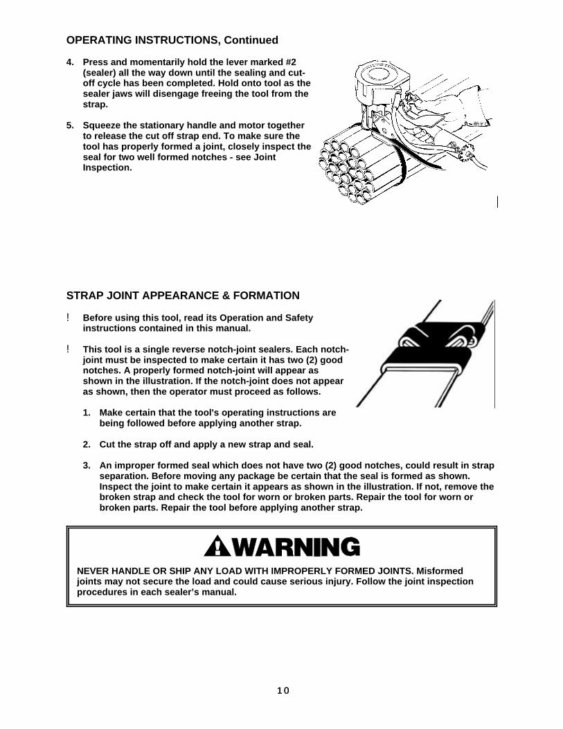
4. Press and momentarily hold the lever marked #2(sealer) all the way down until the sealing and cut-off cycle has been completed. Hold onto tool as thesealer jaws will disengage freeing the tool from thestrap.
5. Squeeze the stationary handle and motor togetherto release the cut off strap end. To make sure thetool has properly formed a joint, closely inspect theseal for two well formed notches - see JointInspection.
STRAP JOINT APPEARANCE & FORMATION
! Before using this tool, read its Operation and Safetyinstructions contained in this manual.
! This tool is a single reverse notch-joint sealers. Each notch-joint must be inspected to make certain it has two (2) goodnotches. A properly formed notch-joint will appear asshown in the illustration. If the notch-joint does not appearas shown, then the operator must proceed as follows.
1. Make certain that the tool's operating instructions arebeing followed before applying another strap.
2. Cut the strap off and apply a new strap and seal.
3. An improper formed seal which does not have two (2) good notches, could result in strapseparation. Before moving any package be certain that the seal is formed as shown.Inspect the joint to make certain it appears as shown in the illustration. If not, remove thebroken strap and check the tool for worn or broken parts. Repair the tool for worn orbroken parts. Repair the tool before applying another strap.
NEVER HANDLE OR SHIP ANY LOAD WITH IMPROPERLY FORMED JOINTS. Misformed joints may not secure the load and could cause serious injury. Follow the joint inspection procedures in each sealer’s manual.

1111
PART REMOVAL, REPLACEMENT & ADJUSTMENTS
REFER TO PAGES 12, 13, 14 & 15 FOR ADDITIONAL INFORMATION
FEEDWHEEL & WEAR PAD
1. To replace the feedwheel (Pg13, #3), remove thetwo socket head cap screws (Pg13, #15) andlock washers (Pg13, #48) which secure the outerlink (Pg13, #51).
2. Remove the outer link from the gear housing.
3. Slide the feedwheel off the feedwheel shaft.
4. The wear pad (Pg13, #22) can now be easilyreplaced. Simply press out the wear plug fromthe under side of the tool. Install the wear padwith a new o-ring (Pg13, #17) making sure theplug is solidly seated.
5. Replace the feedwheel and outer link.
6. Check the feedwheel to wear pad clearance. Theclearance between these parts should be .002"to .006" (0.05-0.15mm). Adjust the clearance asrequired by turning the M6 socket head setscrew (Pg15, #14). Turning the adjustment screwclockwise increases the gap.
STRAP TENSION
Strap tension is controlled by air pressure. Use theproper air line piping and lubrication as specified inthis manual. Your air pressure gauge must beaccurate, therefore, confirm its accuracy bycomparing it to a calibrated master gauge.
Adjust strap tension as follows:
1. Make sure the air pressure is set between 70 and90 psig (4.8 - 6.2 bar).
2. Turn the adjustment valve screw (Pg15, #55) found on the underside of the air motor in 1/4turn increments as required. Turn the screw clockwise to decrease tension andcounterclockwise to increase tension.
Strap breakage hazard. 3/4" (19mm) strap can break during tensioning if inlet air pressure to the tool exceeds 90 psig. Strap breakage can result in severe personal injury. Maximum operating pressure is 90 psig.
Never remove the adjusting screw from the tool with the air connected. The screw could become a flying projectile.

1212
OPTIONAL SIDE MOUNT HANGER(PART NUMBER 422404)
The PNSC-2 can be equipped with thisoptional side hanger for applicationswhich require horizontal strapping.
PARTS LIST, TOOL
KEY QTY PART NO. DESCRIPTION
1 1 422499 PNSC2 TENSION UNIT2 1 422482 ENERGIZING SPRING3 1 422472 FEED WHEEL4 2 422801 AIR HOSE ASSEMBLY5 1 422848 FOOT6 1 422410 CYLINDER7 1 020680 O-RING (#112)8 2 422849 FLAT WASHER
.625"OD x .32O"ID x .020"9 1 422477 PISTON10 1 422837 M8 HEX LOCK NUT11 1 023094 O-RING12 1 422459 GASKET13 1 422457 CYLINDER COVER14 1 422460 PROTECTIVE COVER15 15 011214 SHCS M5 x 1616 1 422485 TENSION VALVE SPACER17 4 092772 O-RING (#14)18 1 422851 TENSION VALVE SPRING
LC-032E-1119 2 020701 O-RING
.208"ID x .348OD" x .070"20 1 422416 TENSION VALVE STEM21 1 422415 TENSION VALVE SLEEVE22 1 422487 WEAR PLUG23 1 023043 VALVE SPRING24 3 023046 SEAL25 1 023042 SLEEVE SPACER26 3 023040 VALVE SLEEVE27 2 008596 O-RING (#111)28 1 023041 VALVE STEM29 1 422461 RAM30 1 422462 RAM PIN31 2 422844 JAW LINK (34)
2 422842 JAW LINK (58,12)32 1 306755 LOCK NUT M5 POLY INSERT33 1 012905 FRONT PLATE (34)
1 023030 FRONT PLATE (58) 1 023062 FRONT PLATE (12)
34 2 306394 JAW 134) 2 422832 JAW (58) 2 422450 JAW (12)
35 2 023048 LINK PIN36 2 306392 NOTCHER (34)
2 023026 N0TCHER (58, 12)37 1 023027 NOTCHER SPACER38 2 023O28 SIDE PLATE SPACER39 1 012902 REAR PLATE (34)
1 023031 REAR PLATE (58, 12)40 2 023029 NOTCHER PIN41 1 422839 FSHCS M5 x 2542 2 422802 SEALER PIN43 1 422803 KEEPER44 2 422806 BUSHING GARLOCK
12mm ID x 4mm OD x 8mm LG45 1 422856 N4 x 20 LG TAPER PIN
(DIN 1472)46 1 422476 PIVOT SHAFT47 1 422452 HANDLE48 5 306079 LOCKWASHER M549 1 422809 BEARING TORRINGTON M-681,
3/8 ID x 9/16 OD x 1/2, CL-END50 1 422805 BEARING, GARLOCK MB1008OU,
1OMM ID x 12MM OD x 8MM51 1 422469 OUTER LINK
KEY QTY PART NO. DESCRIPTION
52 1 422464 CUTTER BLOCK53 2 422804 SPRING LC-035C-654 1 422492 ANGLE CUTTER55 2 422835 N5 x 12 DOWEL PIN56 1 433304 WARNING LABEL57 1 422847 HANGER BRACKET58 1 422854 M6 x 40 LG ROLL PIN
(DIN 1481)59 1 020913 O-RING60 1 422858 DOUBLE SEAL O-RING,
QUATTRO SEAL (#112)61 1 251299 N4 x 12 DOWEL PIN62 1 274466 3MM HEX KEY63 1 274467 4MM HEX KEY64 1 422421 SET SCREW, M5 X 12

1313
*** To be serviced only by an authorized Signode Service facility.
NOTES:
1. Reassemble the tension/sealing valve parts using White Lubriplate GR-132 grease(Signode P/N 422792 or equivalent).
2. Reassemble the sealer parts, pivot shaft, cutter and outer link using Black Lubriplate3000W grease (Signode P/N 422793) or equivalent.

1414
PARTS LIST, TENSION UNIT (422299 STD) (422868 HT)
TENSION TENSION UNIT UNIT422299 422868
KEY QTY PART NO. PART NO. DESCRIPTION
1 3 011214 011214 M5 x 16 SHCS2 1 422470 422470 GEAR CASE COVER3 1 422473 422473 GEAR CASE GASKET4 1 023445 023445 BEARING FAFNIR S5K5 1 023421 023421 WORM GEAR6 1 023443 023443 BEARING7 1 422455 422455 GEAR HOUSING8 1 256791 256791 DOWEL PIN 0 5 x 14MM9 1 422474 422474 FEED WHEEL SHAFT10 1 008596 008596 O-RING11 1 422827 422827 BEARING TORRINGTON JT-8912 1 422805 422805 BEARING GARLOCK 1008D(J13 1 422488 422488 RING GEAR LOCK SCREW14 1 422843 422843 M6 x 16 SHSS15 1 422486 422486 LOCK LEVER PIN16 1 422838 422838 LEVER PIVOT PIN17 1 022812 022812 SPRING LEE LC-026C-518 1 422483 422483 TENSION LEVER SPRING19 1 422428 422428 TENSION LEVER20 1 422484 422484 SEAL LEVER SPRING21 1 422493 422493 TENSION LOCK LEVER22 1 422429 422429 SEAL LEVER23 1 422466 422466 RETAINING RING24 1 008756 008756 BEARING FAFNIR 720325* 1 422826 422878 WORM ASSEMBLY26* 3 422471 - 16T IDLER GEAR
3 - 306436 17T IDLER GEAR27 1 422481 422481 RING GEAR28 1 008781 008781 SPACER29 1 422825 422825 GEAR HOUSING30 1 023551 023551 SEAL31 1 422821 422821 MOTOR RING NUT32 1 422823 422823 RETAINING RING33 2 023481 023481 BEARING34* 1 422833 422438 IDLER CARRIER ASSEMBLY35 3 024607 024607 IDLER GEAR36 1 024608 024608 RING GEAR37 1 306612 306612 NEEDLE ROLLER38 1 422822 422822 WASHER PLASTIC39 2 014541 014541 BELLEVILLE WASHER40 1 422819 422819 FRONT END PLATE41 1 422815 422815 CYLINDER42 1 024602 024602 SPACER43 1 422817 422817 ROTOR44 5 422818 422818 VANE45 1 422814 422814 BACK END PLATE46 1 024633 024633 BEARING47 1 422816 422816 ALIGN PIN48 1 422813 422813 MOTOR HOUSING49* 1 422810 422866 DEFLECTOR50 1 422824 422824 MUFFLER51* 1 422811 422865 DEFLECTOR END52 1 024631 024631 AIR MOTOR STRAINER53 1 020704 020704 HANSON PLUG * Items which are unique to each tension unit.54 1 020701 020701 O-RING55 1 422812 422812 RESTRICTION VALVE56 1 422834 422834 RING GEAR SPACER57 1 422853 422853 O-RING (127)

1515
** Use Loctite #242** Use Loctite #242
NOTES:
1. Key number 53 (Hanson Plug P/N 020704) is packaged loose with every new PNSC-2.
2. Air Motors (P/N 422830 & 422862) shown above can be ordered as a separate assemblyfrom Signode Service.

1616
TROUBLESHOOTING
The following items are the most common tool symptoms if problems occur. For symptoms orremedies not shown, contact your Signode service representative for additional information anddetails. The following tool symptoms are shown in this manual:
#1 - Tool runs sluggishly.#2 - Filter-regulator-lubricator is maintained but still runs sluggishly#3 - Motor does not pick up speed when oiled.#4 - Air motor continues to run after sealing/cut-off cycle is completed.#5 - Low joint strength.#6 - Sealer valve sticks or leaks.#7 - Tool will not cut off strap.#8 - Feedwheel milling on strap.#9 - Seal pulls open during tensioning.
#1 SYMPTOM: The tool runs sluggishly.
CAUSE REMEDY
1. The air filter-regulator -lubricator is malfunctioningand is not properly maintained.
1. Check the regulator to see that the correct airpressure is getting to the tool.
2. Check to see the filter unit is clean andfunctioning properly.
3. Examine the lubricator to see there is oilin the bowl and that the oil is seendripping from the sight dome as the tooloperates. This assures the air motor isbeing properly lubricated.
#2 SYMPTOM: The filter-regulator lubricator is properly maintained but the tool still runssluggishly.
CAUSE REMEDY
The motor is dry, hindering it from providing maximumperformance.
Pour a teaspoon of oil into the motor through the airinlet, hook the tool up to air and run it. An increase ofspeed indicates the motor was dry.
#3 SYMPTOM: The motor does not pick up speed with the addition of oil.
CAUSE REMEDY
The tool may run sluggishly due to clogged or dirtymotor filter screen due to a lack of properly filtered airsupply.
Remove the Hansen plug at the inlet to the air motorand examine the filter screen in the air strainer andclean it if necessary. See instructions on installing theHansen plug.
#4 SYMPTOM: Air motor continues to run after sealing/cut-off cycle is completed.
CAUSE REMEDY
Excessive air line pressure. Install Filter-Regulator-Lubricator near tool. Reduce airpressure to 90 psi (6.2 bar) maximum.

1717
#5 SYMPTOM: Low joint strength.
CAUSE REMEDY
Worn jaws, notchers and pins in jaw stack. Disassemble jaw stack and replace worn parts asrequired.
#6 SYMPTOM: Sealer valve sticks or leaks.
CAUSE REMEDY
1. Dirt in sealer valve assembly.
2. O-Rings and seals in valve stem are worn or
defective.
1. Disassemble and clean valve assembly.
2. Disassemble and replace O rings andseal as required.
#7 SYMPTOM: Tool will not cut off strap.
CAUSE REMEDY
1. Lead edge on breaker foot worn. Inadequate airpressure.
2. Excessive pressure drop due to air line supplyrestrictions.
3. Worn cutter.
1. Replace breaker foot. Increase airpressure to 90 psi (6.2 bar) maximum.
2. Use 3/8" I.D. hose of minimum length.
3. Replace cutter.
#8 SYMPTOM: Feedwheel milling on strap.
CAUSE REMEDY
1. Feedwheel is clogged with dirt.
2. Feedwheel is worn or has chipped teeth.
1. Clean teeth on feedwheel with wirebrush (P/N 269589).
2. Replace feedwheel.
#9 SYMPTOM: Seal pulls open during tensioning.
CAUSE REMEDY
Tool is pulling excessive tension. Lower the strap tension by turning the valve screw(Key 55 on page 15) clockwise. Note, do not turn thestrap tension screw more than one rotation at a timewithout testing tool.

1818
TOOL MAINTENANCE
The most common reason for poor tool performance and incorrectly formed straps joints isimproper tool maintenance. The easiest way to determine if a tool is performing correctly is byinspecting the strap joint. Having a tool maintenance program is a simple task which consists ofthree parts. First, a quick daily inspection of the tool for any worn or broken parts. Secondly,keep each tool on a schedule of service intervals for cleaning and lubrication. Third, whenproblems do occur, use the troubleshooting guide to properly determine and fix problems beforethey lead to more serious tool conditions. Each of these three tasks have been outlined for thisparticular tool, read and understand all information for improving the life and performance of thetool.
TOOL INSPECTION
Visually inspect the exterior of the tool on a daily basis. Decreased tool life can be prevented byearly detection of broken parts. Replace all broken parts with new parts. Review the PartsRemoval, Replacement & Adjustments portion of this manual for information and details.
SERVICE INTERVALS
This tool, like most Signode tools, can be used with various sizes of strap which cause differentrates of component wear. Also, wear is affected by the environment and tension that the toolapplies. In the worst case, heavy gauge wide strapping. All critical moving components of thetool should be inspected at particular intervals, some more often than others. Broken parts candecrease sealing effort, leading to additional component wear and produce lower joint strength.
Inspect the components of the sealing mechanism when:
A. Joint does not appear as shown in this manual or visually it is detected that the joint isnot all formed or formed improperly.
B. Sealing effort requires higher air pressure or tool is difficult to remove from strap.C. When scheduled.
If there is any question that joint formation is not as shown or issuspect, it is important that you contact your tool representative immediately.
The feed wheel and wear plug are also subject to wear and chipping. A daily cleaning of theseparts by brushing off debris will be important to maintaining long life. The first indication of wearwill be strap slippage during tensioning. The operator of the tool should be instructed on how todetermine when the strap slips during tensioning. Sometimes the teeth need to be cleaned with awire brush, but if slipping is allowed to continue, the parts will need to be replaced. Using thetool in a dirty environment will increase feedwheel wear.
NOTE: On some Signode tools the feedwheel can be cleaned by holding the tool open in thestrap loading position while the tool runs without strap and using a wire brush to clean thefeedwheel as it rotates.
Inspect the components of the tensioner mechanism when:
A. Strap slips when being tensioned. B. Evidence of feedwheel milling on the strap face.C. When scheduled.
TOOL LUBRICATION
Signode tools use a variety of greases and oils, all of which can be ordered through Signode.When ordering indicate tool model, part number and name.

1919
EU Declaration of ConformityThe Supply of Machinery (safety) Regulations
1992 (S.I. 1992/3073)
It is hereby declared that the undermentioned machinery has been designed andconstructed to comply with the health and safety requirements defined in EC Directive89/392/EEC
Machine Supplier: Signode, Division of ITW Ltd.Queensway, FforestfachSwansea SA5 4ED
Machine Description: PNSC-2 Series
Machine Type: Pneumatic Combination Hand Strapping tool.
Provisions with which machine complies:
89/392/EEC, 91/368/EEC
Harmonized EuroNorms with which machine complies:
EN 292:1, EN 292:2, EN 294, EN 349
Technical Standards with which machine complies:
NA
Signature: Date: 2 DEC 1996
(Peter Oseland)
© Copyright 2002, Signode 286188 Rev. 4/2002
SIGNODENEW TOOL WARRANTY
Signode Engineered Products Warrants that a new Signode strapping tool will operate per functionalspecifications for a period of sixty (60) days after the date of shipment to the owner's place of business.Normal wearing parts, as outlined in the Operation, Parts & Safety manual, are covered by a thirty (30)day warranty unless, in Signode's judgement, these parts have been subjected to abnormal or extremeusage. Signode's sole liability hereunder will be to repair or replace, without charge, F.O.B. Signode'sGlenview, Illinois plant, any tool which proves to not operate per functional specifications within thestated period. Signode reserves the right to replace any tool which proves not to operate per functionalspecifications with a new or like-new tool of the same model if in Signode's judgement such replacementis appropriate. Any new replacement tool provided to an owner will carry a full sixty (60) day warranty.Any warranty repaired tool or like-new replacement tool will carry a warranty for the balance of the timeremaining on the initial sixty (60) day warranty. This warranty will be extended to compensate for thetime the tool is in Signode's possession for warranty repairs.
This warranty is void as to any tool which has been: (I) subjected to mis-use, misapplication, accident,damage, or repaired with other than genuine Signode replacement parts, (II) improperly maintained, oradjusted, or damaged in transit or handling; (III) used with improperly filtered, unlubricated air orimproper strapping material, (IV) in Signode's opinion, altered or repaired in a way that affects ordetracts from the performance of the tool.
SIGNODE MAKES NO WARRANTY, EXPRESSED OR IMPLIED, RELATING TO MERCHANTABILITY,FITNESS OR OTHERWISE EXCEPT AS STATED ABOVE AND SIGNODE'S LIABILITY AS ASSUMED ABOVEIS IN LIEU OF ALL OTHERS ARISING OUT OF OR IN CONNECTION WITH THE USE AND PERFORMANCEOF THE TOOL. IT IS EXPRESSLY UNDERSTOOD THAT SIGNODE SHALL IN NO EVENT BE LIABLE FORANY INDIRECT OR CONSEQUENTIAL DAMAGES INCLUDING, BUT NOT LIMITED TO, DAMAGES WHICHMAY ARISE FROM LOSS OF ANTICIPATED PROFITS OR PRODUCTION, SPOILAGE OF MATERIALS,INCREASED COSTS OF OPERATION OR OTHERWISE.
Considerable effort has be made to ensure that this product conforms to our high quality standards.However, should you experience any difficulties, please contact your Sales Representative providingsamples and the manufacturing code specified on the tool.
Thank you for your help.
SIGNODE ENGINEERED PRODUCTSHand Tool Division
3620 W. Lake Avenue, Glenview, Illinois 60025