
Wireless smart thermostat PNI CT35 Internet controlled for ...
Upload
truongdangCategory
view
215download
0
PNI Corporation
TCM2 Electronic Sensor ModuleUser’s Guide

ii
© Copyright PNI Corporation 2004All Rights Reserved. Reproduction, adaptation, or translation with-out prior written permission is prohibited, except as allowed under copyright laws.
Part No. 10824Document No. 1000281Revision 3.0February 2004Printed in USA
PNI Corporation 5464 Skylane Blvd., Suite ASanta Rosa, CA 95403, USATel: (707) 566-2260Fax: (707) 566-2261
Notice.The information contained in this document is subject to change without notice. Companies, names, and data used in examples herein are fictitious unless otherwise noted. PNI Corporation makes no warranty of any kind with regard to this material, includ-ing but not limited to, the implied warranties of merchantability and fitness for a particular purpose. PNI Corporation shall not be liable for errors contained herein or for incidental or consequential damages in connection with the furnishing, performance, or use of this material.
Restricted Rights Legend.Use, duplication, or disclosure by the U.S. Government is subject to restrictions as set forth in subparagraph (c) (1) (ii) of the Rights in Technical Data and Computer Software clause at DFARS 252.227-7013 for DOD agencies, and subparagraphs (c) (1) and (c) (2) of the Commercial Computer Software Restricted Rights clause at FAR 52.227-19 for other agencies.
Conventions Used in this Manual.Any data that is sent to or received from the TCM2 is presented in monospace font, for example: $C326.3*check-sum<cr><lf>. Place markers for ASCII characters are indi-cated by the character “n.” Any monospace characters in straight brackets denote transmitted data that may or may not be in the character string, depending on the circumstances. For instance [Ennn] is the error code string that is output by the TCM2 only when an error condition exists. Also,(-) denotes the presence of a negative sign in a character string when the corresponding value is negative. The parentheses are not included in the output string, and only serve to demark the hyphen.
TCM2 commands can be identified either by their mnemonic, for example, h, or by their full name, for example, Halt continuous sampling.
Items in angle brackets either denote special characters or sum-mary data, for example, <cr> denotes the carriage return character, <lf> denotes a line feed, and <error code> denotes all the charac-ters for an error code string.
Warranty.PNI warrants that each PNI Product to be delivered hereunder, if properly used, will be free from defects in material and workman-ship and will operate in accordance with PNI’s published specifica-tions and documentation for the Product in effect at time of order acceptance if operated as directed by them for one year following the date of shipment unless a different warranty time period for such Product is specified: (i) in PNI’s Price List in effect at time of order acceptance; or (ii) on PNI’s web site (www.pnicorp.com) at time of order acceptance. PNI will make no changes to the specifi-cations or manufacturing processes that affect form, fit, or function of the product without written notice to the OEM. PNI may at any time make minor changes to specifications or manufacturing pro-cesses that do not affect the form, fit, or function of the product. This warranty will be void if the products, serial number, or other identification marks have been defaced, damaged, or removed. This warranty does not cover wear and tear due to normal use, or damage to the product as the result of improper usage, neglect of care, alteration, accident, or damage to the product as the result of improper usage, neglect of care, alteration, accident, or unautho-rized repair.
THE ABOVE WARRANTY IS IN LIEU OF ANY OTHER WAR-RANTY, WHETHER EXPRESS, IMPLIED, OR STATUTORY, INCLUDING, BUT NOT LIMITED TO, ANY WARRANTY OF MERCHANTABILITY, FITNESS FOR ANY PARTICULAR PURPOSE, OR ANY WARRANTY OTHERWISE ARISING OUT OF ANY PROPOSAL, SPECIFICATION, OR SAMPLE. PNI NEITHER ASSUMES NOR AUTHORIZES ANY PERSON TO ASSUME FOR IT ANY OTHER LIABILITY.
If any PNI Product furnished hereunder fails to conform to the above warranty, OEM’s sole and exclusive remedy and PNI’s sole and exclusive liability will be, at PNI’s option, to repair, replace, or credit OEM’s account with an amount equal to the price paid for any such Product which fails during the applicable warranty period provided that (i) OEM promptly notifies PNI in writing that such Product is defective and furnishes an explanation of the deficiency; (ii) such Product is returned to PNI’s service facility at OEM’s risk and expense; and (iii) PNI is satisfied that claimed deficiencies exist and were not caused by accident, misuse, neglect, alteration, repair, improper installation, or improper testing. If Product is defective, transportation charges for the return of Product to OEM within the United States and Canada will be paid by PNI. For all other locations, the warranty excludes all costs of shipping, cus-toms clearance, and other related charges. PNI will have a reason-able time to make repairs or to replace Product or to credit OEM’s account. PNI warrants any such repaired or replacement product to be free from defects in material and workmanship on the same terms as the product originally purchased.
Contents
1 Getting StartedAbout the TCM2 1-2
Packing List 1-3Products and Accessories 1-3
Installation 1-4Electrical Connections 1-4Communicating with the TCM2 1-6Evaluation Software 1-6Where to Install the TCM2 1-7Mechanically Mounting the TCM2 1-8
2 Using the TCM2RS232 Data Output Word 2-2
NMEA 0183 Format 2-2TCM2 Standard Output 2-3
Command Syntax 2-4Programming Conventions 2-4
Data Transmission 2-5Error Codes 2-6
Description of Error Conditions 2-7Compass Operating Modes 2-8
Standby Mode 2-8Sampling in the Standby Mode 2-8Continuous Sampling Mode 2-8Analog Outputs 2-9
Digital Damping 2-10Output Response Time 2-11Latency 2-12Magnetic Distortion Alarm 2-13
How to Use the Magnetic Distortion Alarm 2-13How to Interpret the Magnetic Distortion Alarm 2-13
Pitch and Roll Output 2-14 User Calibration 2-15
Automatic Calibration 2-16Soft Iron Effects 2-17Other Limitations 2-17
Calibration Procedures 2-18Multipoint Calibration (mpcal) 2-19CAL3 Procedure 2-20Temperature Sensor Calibration 2-22
3 Programming CommandsCommand List Quick Reference 3-2Differences Between TCM2 Firmware Version 2.82 and 2.34A 3-4
Changes to the EEPROM 3-4Command List 3-5Request for Data Commands 3-6Action Commands 3-11User Configuration Parameter Commands 3-17
4 TroubleshootingTrouble-Shooting the TCM2 4-2Limitations of the Inclinometer 4-6
Contents-1

5 Performance SpecificationSpecifications 5-2
Assembly Views 5-33-Foot Cable 5-6Optional 6-Foot Cable 5-8
Contents-2

1
About the TCM2 1-2Installation 1-4
Packing List 1-3Electrical Connections 1-4Communicating with the TCM2 1-6Evaluation Software 1-6Where to Install the TCM2 1-7Mechanically Mounting the TCM2 1-8
Getting Started
Getting StartedAbout the TCM2
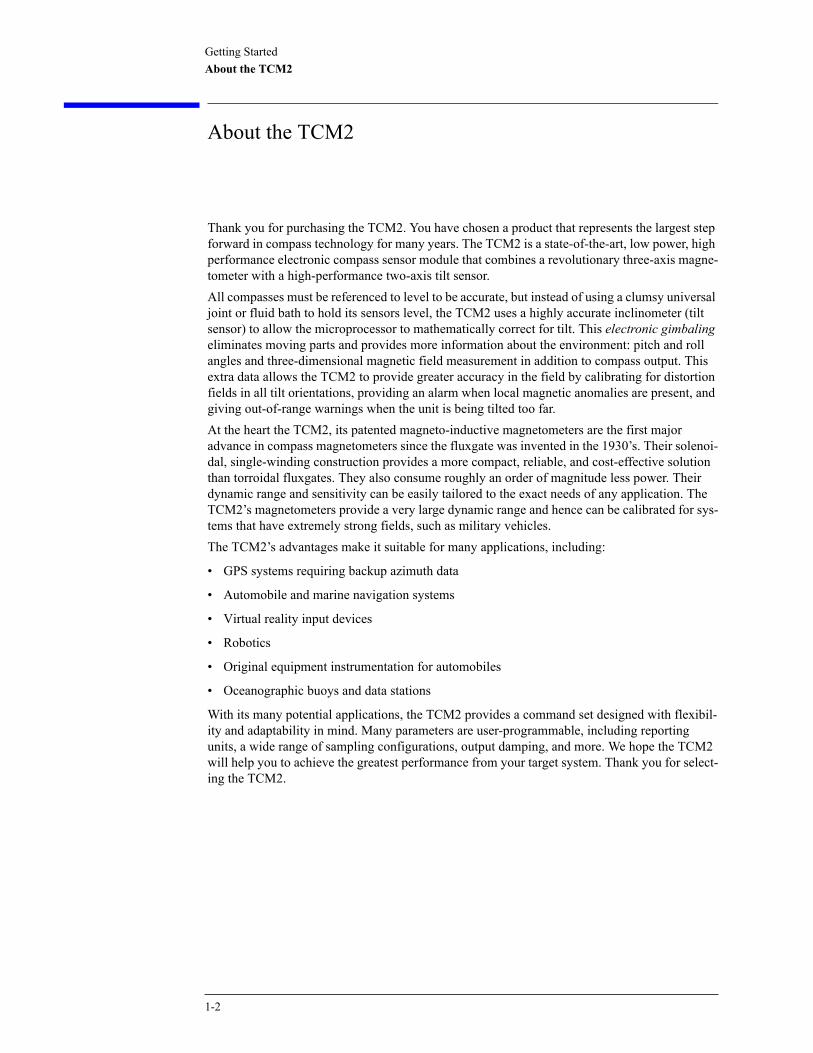
About the TCM2
Thank you for purchasing the TCM2. You have chosen a product that represents the largest step forward in compass technology for many years. The TCM2 is a state-of-the-art, low power, high performance electronic compass sensor module that combines a revolutionary three-axis magne-tometer with a high-performance two-axis tilt sensor. All compasses must be referenced to level to be accurate, but instead of using a clumsy universal joint or fluid bath to hold its sensors level, the TCM2 uses a highly accurate inclinometer (tilt sensor) to allow the microprocessor to mathematically correct for tilt. This electronic gimbaling eliminates moving parts and provides more information about the environment: pitch and roll angles and three-dimensional magnetic field measurement in addition to compass output. This extra data allows the TCM2 to provide greater accuracy in the field by calibrating for distortion fields in all tilt orientations, providing an alarm when local magnetic anomalies are present, and giving out-of-range warnings when the unit is being tilted too far. At the heart the TCM2, its patented magneto-inductive magnetometers are the first major advance in compass magnetometers since the fluxgate was invented in the 1930’s. Their solenoi-dal, single-winding construction provides a more compact, reliable, and cost-effective solution than torroidal fluxgates. They also consume roughly an order of magnitude less power. Their dynamic range and sensitivity can be easily tailored to the exact needs of any application. The TCM2’s magnetometers provide a very large dynamic range and hence can be calibrated for sys-tems that have extremely strong fields, such as military vehicles. The TCM2’s advantages make it suitable for many applications, including:
• GPS systems requiring backup azimuth data
• Automobile and marine navigation systems
• Virtual reality input devices
• Robotics
• Original equipment instrumentation for automobiles
• Oceanographic buoys and data stations
With its many potential applications, the TCM2 provides a command set designed with flexibil-ity and adaptability in mind. Many parameters are user-programmable, including reporting units, a wide range of sampling configurations, output damping, and more. We hope the TCM2 will help you to achieve the greatest performance from your target system. Thank you for select-ing the TCM2.
1-2

Getting StartedAbout the TCM2
Packing List
Your TCM2 Evaluation Kit should contain the following items:
TCM2 Electronic Sensor Module
Interface Cable, 3 foot (optional 6-foot cable available for purchase)
Connects between the TCM2 and the host system and power supply. Refer to “TCM2 Pin Descriptions” on page 1-4 for a complete description.
User's Guide
3.5" floppy disk containing TCM2 evaluation software
The 3.5" floppy is a high-density disk formatted for DOS systems. It contains the TCM2.EXE program that executes on any IBM-AT compatible computer running DOS. For instructions on installing and using the TCM2.EXE program, refer to “Evaluation Software” on page 1-6.If any of the 4 items are missing please contact PNI Corp.
C A U T I O N The TCM2 board is an ESD-sensitive device and must be handled accordingly.
Products and Accessories
Table 1-1. Products and Accessories
Product Part Number
TCM2-20 10639
TCM2-20 (with user’s guide, 3-ft. cable, and software) 90001
TCM2-50 10651
TCM2-50 Includes user’s guide, 3-ft. cable, and software) 90002
TCM2 Inclinometer only 10657
TCM2 Inclinometer only(with user’s guide, 3-ft. cable, and software) 90003
TCM2 Magnetometer only 10660
TCM2 Magnetometer only(with user’s guide, 3-ft. cable, and software) 90004
Accessories
6-ft. cable 10826
User’s Guide 10824
1-3

Getting StartedInstallation
Installation
This section describes how to configure, program, and control the TCM2 in your target system. To install the TCM2 into your system, follow these steps:
Make electrical connections to the TCM2
Evaluate the software
Choose a mounting location
Mechanically mount the TCM2
Calibrate for hard-iron distortion effects using either the MPCAL or CAL3 calibration proce-dures.
Electrical Connections
The TCM2 evaluation kit contains a cable to connect to the TCM2. On one end of the cable is the connector needed to mate to the TCM2. The header is MOLX 22-03-2101style, with 0.100” centers. The mating receptacle is MOLX 22-01-3107, or equivalent. The crimps are MOLX 08-50-0114). The cable’s wires are color coded as indicated below:PNI also has a 6-foot cable with a DB9 connector attached. Contact PNI Corporation for pur-chasing information.
Table 1-2. TCM2 Pin Descriptions
Pin Wire Color Description
1 Orange Vsupply (5 V regulated (±5%)) a
a. Do not apply power to both pin 1 and pin 2 simultaneously.
2 Red Vsupply (6-18 V unregulated) a
3 Black Power Ground
4 Blue RxD (RS-232) –5 to 5 V
5 Yellow TxD (RS-232) –5 to 5 V or –12 to 12 V. These ranges are compatible with most RS-232 chips.
6 White RTS, Wake from Sleep
7 Green Data ground, connected to the RS-232 ground
8 Brown Analog Output 2
9 Purple Analog Output
10 Gray Data Ground
1-4
Getting StartedInstallation
Procedure
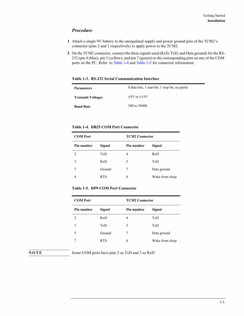
1 Attach a single 9V battery to the unregulated supply and power ground pins of the TCM2’s connector (pins 2 and 3 respectively) to apply power to the TCM2.
2 On the TCM2 connector, connect the three signals used (RxD, TxD, and Data ground) for the RS-232 (pin 4 (blue), pin 5 (yellow), and pin 7 (green)) to the corresponding pins on one of the COM ports on the PC. Refer to Table 1-4 and Table 1-5 for connector information.
Table 1-5. DP9 COM Port Connector
N O T E Some COM ports have pins 2 as TxD and 3 as RxD.
Table 1-3. RS-232 Serial Communication Interface
Parameters 8 data bits, 1 start bit, 1 stop bit, no parity
Transmit Voltages ±5V to ±15V
Baud Rate 300 to 38400
Table 1-4. DB25 COM Port Connector
COM Port TCM2 Connector
Pin number Signal Pin number Signal
2 TxD 4 RxD
3 RxD 5 TxD
7 Ground 7 Data ground
4 RTS 6 Wake from sleep
COM Port TCM2 Connector
Pin number Signal Pin number Signal
2 RxD 4 TxD
3 TxD 5 TxD
5 Ground 7 Data ground
7 RTS 6 Wake from sleep
1-5

Getting StartedInstallation
Communicating with the TCM2
Once the TCM2 is powered up and the RS232 connection is made with one of the PC’s COM ports, you may begin swapping ASCII serial data with the TCM2. The most direct means is to run any modem or terminal emulation software.Specify the COM port that you have the TCM2 connected to and set the baud rate to the same baud rate of the TCM2. The default baud rate for the TCM2 is 9600. Remember that the TCM2 does not echo characters by default, so you may wish to select the echo output option in your terminal emulation program or press <Ctrl> e on the keyboard.
Evaluation Software
The TCM2.exe DOS evaluation program communicates with the TCM2 through the COM port of your PC. It puts an easy-to-use interface onto the ASCII command language used by the TCM2, so that instead of issuing command codes manually, you can use buttons, check boxes, and dialog boxes. It reads the ASCII responses of the TCM2 instead of reading the ASCII output strings of the TCM2 and formats its sensor data into labeled and easy-to-read data fields. It simultaneously presents a terminal window that shows you the actual ASCII strings being exchanged with the TCM2, so that you may observe and begin to learn the TCM2’s command syntax as you use the evaluation program’s more friendly interface.To install the program on your computer, copy the TCM2.EXE file from the floppy disk to your hard drive. Usage of the program is menu-driven. There are three ways to navigate the menu buttons.
• Use the keyboard’s Tab key to move sequentially through the menu items.
• Use the keyboard’s arrow keys to move through the menu items.
• On the keyboard, enter the shortcut key (the key in the menu item that is white) to go directly to that menu item. For example, the Set Program i/o Parameters button the “P” in Program is white in color.
N O T E The TCM2.EXE program cannot use the 38400 baud rate. Do not use TCM2.exe to change the baud rate to 38400. If the TCM2 is set to 38400 (b=7), the TCM2.exe program will not be able to communicate with the PC.
The 38400 baud rate can be used with other terminal programs that support this rate. Examples of these programs are TELIX, PROCOMM, and HyperTerminal in the Accessories list of Windows. When using a terminal program you will need to set the correct baud rate, no parity, 1 stop bit, 8 data bits and the COM port.
The TCM2.exe program will default to COM2 and baud rate of 9600. To start the TCM2.exe program on COM1, invoke the TCM2.EXE program with the following command:
TCM2 1 (TCM2 "space" 1)
Alternately, the COM Port and baud rate can be set in the TCM2.EXE program.
N O T E The Compass Baud Rate and the Program Baud Rate must be the same. In general, you should set the Compass Baud Rate before changing the Program Baud Rate.
To set the Compass baud rate, and the TCM2.EXE program baud rate and COM port:
1 From the TCM2.EXE program, select Set Compass I/O Parameters, set the Baud Rate to the desired value, and then select OK.
1-6

Getting StartedInstallation
2 Select Set Program I/O Parameters, choose the correct COM Port and Baud Rate, and then press OK.
The bottom screen echos the commands when the different buttons are selected. It can also serve as a terminal program by pressing the F1 key. In the terminal mode, you can type commands directly to the TCM2. To return to user interface control, press the F2 key.The program also includes a data logging feature. In the Program I/O Parameters menu, you can open a data file (Logging on enabled). After you open the data file, all of the data going to or coming from the TCM2 compass will be saved to the file. When you are done collecting data, close the data file. The file is saved in ASCII text.
Where to Install the TCM2
The TCM2’s magnetometers’ wide dynamic range and its sophisticated calibration algorithms allow it to operate in many environments. For optimal performance however, you should mount the TCM2 with the following considerations in mind:
The TCM2’s magnetometers should not saturate
The TCM2 can be calibrated for large static magnetic fields. However, each axis of the TCM2’s magnetometers has a maximum dynamic range of ±80 µT; if the total field exceeds this value for any axis, the TCM2 will report a magnetometer out of range error condition. When mounting the TCM2, consider the effect of any sources of magnetic fields in the local environment that when added to the earth’s field may saturate the TCM2’s sensors. For example, large masses of ferrous metals such as transformers and vehicle chassis, large electric currents, permanent mag-nets such as electric motors, and so on.
Locate the TCM2 away from local sources of changing magnetic fields
It is not possible to calibrate for changing magnetic anomalies. Thus, for greatest accuracy, keep the TCM2 away from sources of local magnetic anomalies that will change with time; for instance, electric equipment that will be turned on and off or nearby ferrous bodies that will be changing positions. Make sure the TCM2 is not mounted close to cargo or payload areas that may be loaded with large sources of local magnetic fields. To test the magnetic environment of a location:
1 Clear any previous calibration data:
• On the terminal program, send the command cc <Enter>.
• On the TCM2.exe program, select User Calibration, Clear Previous Calibration. After a few seconds, the Start Multipoint Calibration button will be displayed. Select Quit.
2 Set the TCM2 to output the X, Y, and Z sensor data.
• On the terminal program, send the command em=e.
• On the TCM2.exe program, select Set Compass I/O Parameters and then set the Magnetom-eter Output to Enabled.
3 Put the TCM2 into Continuous Output mode:
• On the terminal program, send the command go.
• On the TCM2.exe program, select Start Continuous Sampling.
4 Place the unit in the desired mounting location and note the magnetometer output X, Y, and Z
1-7

Getting StartedInstallation
values. If you see a Magnetometer Out of Range error, ignore it for now.
5 Pick a direction to begin moving the TCM2, either forward or backward (X sensor), side-to-side (Y sensor), or up or down (Z sensor). The process will eventually go through all combinations with the intent of moving away from any distortions until a location can be found where the TCM2 will be able to operate.
6 Slowly move the TCM2 in the first direction only, until the values of the corresponding sensor stop changing with the movement, or at least the change can be attributed to background noise. It may be that the sensor will still be changing, but it is the least amount of change seen.
7 Select the next direction to move, starting at the finishing point of the previous move. Continue until this sensor’s values stop changing as in the step above.
8 Finally, move the TCM2 along the final sensor direction as done previously. At the end of this movement, the location achieved is the best location to mount the TCM2 relative to the initial desired location.
9 Experiment with different configurations of cargo, as well as turning various equipment on and off to determine if the TCM2’s sensors saturate or detect significant changes in local magnetic anomalies.
Example Test Scenario
The TCM2 starts at point A, which is directly behind an antenna mounted on the top of a van. Begin by moving the TCM2 rearward, away from the antenna along the X axis. At some dis-tance the X values stop changing significantly with movement. From that point begin moving the TCM2 to the right along the Y axis, maintaining the relative rearward location already deter-mined, until the Y sensor stops changing. From this end point move the TCM2 upward along the Z axis. At some point the Z value will have little change. Thus, the best mounting position is achieved.
The TCM2 should be mounted in a physically stable location
Choose a location that is isolated from excessive shock, oscillation, and vibration.
The TCM2 should be mounted as close to level as possible
To maximize the tilt range over which the compass operates, the TCM2 should be mounted as close to level as possible, as indicated by the Pitch and Roll output of the TCM2.
Mechanically Mounting the TCM2
Refer to the TCM2 Dimensional Specification in Chapter 5, “Performance Specification” for the TCM2 board dimensions, location of the mounting holes, and the orientation of the reference frame. The TCM2 is factory calibrated with respect to the mounting holes, thus it must be aligned within the host system with respect to these mounting holes, not the board edges.
1-8

2
RS232 Data Output Word 2-2NMEA 0183 Format 2-2TCM2 Standard Output 2-3
Command Syntax 2-4Programming Conventions 2-4
Data Transmission 2-5Error Codes 2-6Compass Operating Modes 2-8
Standby Mode 2-8Sampling in the Standby Mode 2-8Continuous Sampling Mode 2-8Analog Outputs 2-9
Digital Damping 2-10Output Response Time 2-11Latency 2-12Magnetic Distortion Alarm 2-13Pitch and Roll Output 2-14 User Calibration 2-15
Automatic Calibration 2-16Soft Iron Effects 2-17Other Limitations 2-17
Calibration Procedures 2-18Multipoint Calibration (mpcal) 2-19CAL3 Procedure 2-20Temperature Sensor Calibration 2-22
Using the TCM2

Using the TCM2RS232 Data Output Word
RS232 Data Output Word
The TCM2 sends an “output word” in ASCII form across the RS232 serial link when issued the s? (Single Output Word) command, or when in go (Continuous Sampling) mode. This data out-put word may be configured by the user for the desired format and configuration. You may select either NMEA 0183, or TCM2 standard output word formats, with the sdo= (Set RS-232 Output Word) command.
NMEA 0183 Format
The TCM2 can be configured to conform to the NMEA (National Maritime Electronics Associ-ation) 0183 specification, which describes a standard RS232 bus format for exchange of a vari-ety of navigation information (GPS, radar, compass, and so on). In the NMEA output format, only compass heading information is available. Inclinometer, magnetometer, thermometer data and the distortion detection warning are all unavailable.
$HCHDM,<compass>,M*checksum<cr><lf> !for magnetic heading
For example,
$HCHDM,182.3,M*checksum<cr><lf> !for magnetic heading = 182.3 °
The checksum value is the result of XOR’ing the ASCII bytes between the ‘$’ and ‘*’ charac-ters. This one byte value is reported in the output word by two ASCII characters representing two hex digits, with the most significant nibble first. For example, “...*A3<cr><lf> “indi-cates that the output word has a decimal checksum value of 163.
2-2

Using the TCM2RS232 Data Output Word
TCM2 Standard Output
The TCM2 standard output format may be configured to provide all of the sensor data parame-ters available, or only those parameters required.
$C<compass>P<pitch>R<roll>X<Bx>Y<By>Z<Bz>T<temp>E<error code>*checksum<cr><lf>
For detailed information regarding the character formatting and resolution of the values for each of the data parameters in the output word, refer to “Programming Commands” on page 3-1 for the following commands: c? (Compass Update), m? (Magnetometer Update), i? (Inclinometer Update), t? (Temperature Update).
Example
The TCM2 will return the following:
$C328.3P28.4R-12.4X55.11Y12.33Z-18.43T22.3E001*checksum<cr><lf>
under the following conditions:
• compass heading = 328.3 ° (true or magnetic, depending on configuration)
• pitch = 28.4 °
• roll = -12.4 °
• Bx = 55.11µT (x-component of magnetic field)
• By = 12.33 µT (y-component of magnetic field)
• Bz = -18.43 µT (z-component of magnetic field)
• Temperature = 22.3 ° (F/C depending on configuration)
• E001 = Distortion flag is raised–magnetic anomaly nearby
Any parameters not enabled are not included in the output word. For example:
$C328.3T22.3*checksum<cr><lf> !for compass and thermometer information only.
If all data parameters are disabled, no message will be output in response to s? or in continuous output mode, unless an error condition exists. The checksum value is computed and reported identically to that for the NMEA output format.
2-3

Using the TCM2Command Syntax
Command Syntax
There are three types of commands you may issue to the TCM2:
• User Configuration Parameter commands which set user-definable parameters.
• Request for Data commands which query the TCM2 for data or for the stored value of user-definable parameters.
• Action commands which prompt the TCM2 to perform a specific action.
All commands must be followed with a <cr>, or <cr><lf>. The <lf> characters are ignored by the TCM2, but are supported to allow compatibility with a variety of terminals.
Programming Conventions
Set TCM2 user parameters: <parameter>=<value><cr>
Query TCM2 data (parameter or sensor values): <parameter>?<cr>
Action command: <command><cr>
Detailed descriptions of all commands are in the “Command List” on page 3-5 and a command summary is shown in “Command List Quick Reference” on page 3-2.
2-4
Using the TCM2Data Transmission
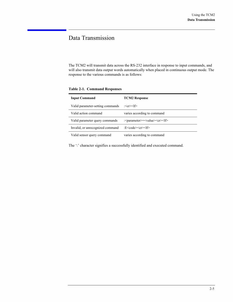
Data Transmission
The TCM2 will transmit data across the RS-232 interface in response to input commands, and will also transmit data output words automatically when placed in continuous output mode. The response to the various commands is as follows:
The ‘:’ character signifies a successfully identified and executed command.
Table 2-1. Command Responses
Input Command TCM2 Response
Valid parameter-setting commands :<cr><lf>
Valid action command varies according to command
Valid parameter query commands :<parameter>=<value><cr><lf>
Invalid, or unrecognized command :E<code><cr><lf>
Valid sensor query command varies according to command
2-5
Using the TCM2Error Codes
Error Codes
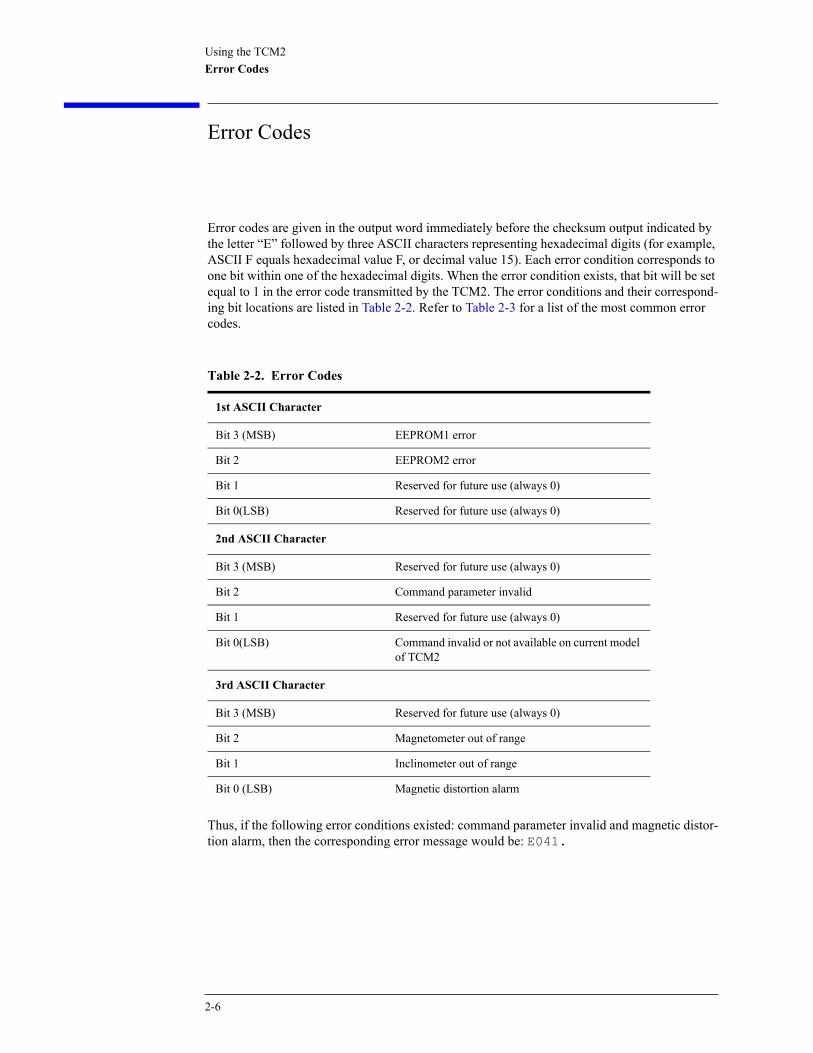
Error codes are given in the output word immediately before the checksum output indicated by the letter “E” followed by three ASCII characters representing hexadecimal digits (for example, ASCII F equals hexadecimal value F, or decimal value 15). Each error condition corresponds to one bit within one of the hexadecimal digits. When the error condition exists, that bit will be set equal to 1 in the error code transmitted by the TCM2. The error conditions and their correspond-ing bit locations are listed in Table 2-2. Refer to Table 2-3 for a list of the most common error codes.
Thus, if the following error conditions existed: command parameter invalid and magnetic distor-tion alarm, then the corresponding error message would be: E041.
Table 2-2. Error Codes
1st ASCII Character
Bit 3 (MSB) EEPROM1 error
Bit 2 EEPROM2 error
Bit 1 Reserved for future use (always 0)
Bit 0(LSB) Reserved for future use (always 0)
2nd ASCII Character
Bit 3 (MSB) Reserved for future use (always 0)
Bit 2 Command parameter invalid
Bit 1 Reserved for future use (always 0)
Bit 0(LSB) Command invalid or not available on current model of TCM2
3rd ASCII Character
Bit 3 (MSB) Reserved for future use (always 0)
Bit 2 Magnetometer out of range
Bit 1 Inclinometer out of range
Bit 0 (LSB) Magnetic distortion alarm
2-6

Using the TCM2Error Codes
Description of Error Conditions
Command Parameter Invalid – contains an invalid or out of range value.
Command invalid or not available on current model of TCM2 – is not recognized by the TCM2. The syntax is incorrect, or you have entered a command which is not supported by the TCM2 model you are using.
Inclinometer out of range – the inclinometer sensor is detecting an attitude that is outside of its operational range of maximum pitch and roll. When this error flag is raised, compass and inclinometer output data should be disregarded. Note that extreme out of range conditions may not be detected. For example, when the inclinometer is upside down due to the physical dimensions of the inclinometer, it could output angles within the range of the inclinometer even though they are not valid angles.
Magnetometer out of range – the magnetometer sensors are detecting an ambient magnetic field that exceeds the maximum dynamic range of the magnetometer in any of the three axes.
Magnetic distortion alarm – the TCM2 is detecting a local magnetic anomaly that may be compromising the accuracy of compass and magnetometer readings. Refer to “Magnetic Distortion Alarm ” on page 2-13 for more details on this feature.
Table 2-3. Common Error Codes
Error Code Description
E001 Magnetic distortion alarm a
a. Indicates that the unit has detected magnetic filed anomalies that can compromise compass and magnetometeraccuracy based upon the stored values of the last calibration. Refer to “Magnetic Distortion Alarm ” onpage 2-13 for more information.
E002 Inclinometer out of range
E003 Magnetic distortion alarm and inclinometer out of range
E004 Magnetometer out of range
E005 Magnetometer out of range and magnetic distortion alarm
E006 Magnetometer out of range and Inclinometer out of range
E007 Magnetometer out of range, Inclinometer out of range, and magnetic distortion alarm
E010 Command invalid or not available
E040 Command parameter invalid
E050 Command invalid or not available, and command parameter invalid
E400 EEPROM2 error b
b. Indicates that the TCM2 EEPROM has been corrupted. Contact PNI Corporation for assistance.
E800 EEPROM1 error b
EC00 EEPROM2 error and EEPROM1 error b
2-7
Using the TCM2Compass Operating Modes
Compass Operating Modes
Standby Mode
The TCM2 is in Standby mode when you issue an h (Halt) command or ax (Warm Reboot). During Standby mode the TCM2 is idle and not sampling any sensors. You may configure and verify the TCM2’s user parameters in the Standby mode (set sampling rate, filter parameters, and so on.) You may also query the TCM2 for single updates of compass heading, pitch and roll, magnetic field strength, and temperature. Because the TCM2’s sensors are not sampling contin-uously during Standby, filtering is automatically disabled, and power consumption is reduced.
Sampling in the Standby Mode
You can activate and receive data from the TCM2 sensors from the h (Halt Continuous Sam-pling, Enter Standby) mode. You may wish to do this if you are manually operating the TCM2 for evaluation purposes, or if the TCM2 only needs to be polled sporadically. With the TCM2 in the Standby mode, you can query sensor data by either issuing single parameter updates with commands like c? (Compass Update), m? (Magnetometer Update) or you can receive output word updates by issuing the s? (Single Update of Output Word) command. The output word may be configured as previously described in “TCM2 Standard Output” on page 2-3 to provide either NMEA formatted compass data, or the TCM2 Standard output word, which presents any combination of TCM2 sensor data that you wish to receive. The single parameter updates allow you to immediately query any sensor data.
N O T E Because the sensors are not continuously sampling in the Standby mode, data damping is automatically disabled. Thus, any updates you request will not be damped.
Continuous Sampling Mode
After configuring the TCM2 in the Standby mode, issue the go command to place the TCM2 into Continuous Sampling mode. In this mode, the TCM2 samples its sensors, processes, and stores this sensor data at the periodic rate you specify with the sp= (Set Sampling Period Divi-sor), clock= (Set Clock Rate), and fast= (Enable Fast Sampling) commands. The principle means of output from the TCM2 is via RS-232 serial communications. You may configure the TCM2 either to output the latest sensor data on a continuous, unprompted basis, or to provide an update only upon demand.
• continuous output (serial)
• analog output
• quadrature output
2-8
Using the TCM2Compass Operating Modes
The TCM2 will output the specified output word at the chosen period rate. As soon as a new set of sensor data is processed by the TCM2, it is immediately transmitted. As discussed in “RS232 Data Output Word” on page 2-2, the output word can either be NMEA or TCM2 Standard for-mats. The continuous output mode should be utilized if you wish to have the TCM2 automatically pro-vide a periodic output without being prompt by the host system.
Analog Outputs
The TCM2 supports analog output of compass heading data to provide compatibility with a wide range of existing systems. The analog output is enabled by sao=e (Select Analog Output) command. However, analog output modes do not provide full resolution, error flags, tilt data, or magnetic field information, so if you are implementing the TCM2 into a new design, utilizing the RS-232 interface is strongly recommended. There are two analog output formats available: linear and quadrature. Use the Select Analog Output mode command, sao=l (linear) sao=q (quadrature) or sao=d (disabled) to configure the TCM2 to provide the analog output mode that you desire. Refer to “sao=” on page 3-25.
Linear Mode
The TCM2’s digital compass heading is converted to a DC voltage ranging from 0 to 4.98 V by an 8-bit digital-to-analog converter (DAC). Thus, heading resolution is 8 bits (256 increments), around a full circle. Specifically, the 5V range is divided into 19.6 mV increments, where each increment corresponds to a 1.4 ° change in compass heading. Thus, an output voltage of 19.6 mV corresponds to a 1.4 ° compass heading. An output voltage of 2.5 V corresponds to a compass heading of 179.5 °. Note that there is an abrupt switch in out-put voltage at 360 °, from 4.98 V to 0 V.
Quadrature Mode
Two DC voltages provide the sine and cosine of the heading angle, thus eliminating voltage dis-continuities. Analog output 1 (pin 9) is cosine of the heading; analog output 2 (pin 8) is sine of the heading 4.98 V corresponds to sin (heading) or cos (heading) equal to 1.0 V corresponds to sin (heading) or cos (heading) equal to –1. If the compass is facing north, 0 °, you will see 4.98 V at pin 9 (cos (0 °) = 1) and 2.5 V at pin 8 (sin (0 °) = 0).
N O T E You should always place a buffer between the TCM2 analog output and the input of an ADC. The analog output should swing from 0 V to 4.98 V. If you do not see the maximum output reach 4.98 V, you are probably loading the TCM2 analog output.
2-9

Using the TCM2Digital Damping
Digital Damping
Digital damping is used to filter the output (damping=). The damping uses an IIR filter on the measured data. It is only enabled during continuous mode. The digital damping feature com-putes the following:
output=(1-f(timeconst)) x current measurement + f(timeconst) x oldmeasurements
It outputs this as the current measurement and stores it in place of the old measurements. The function f is as follows:
f=10^(log(1/2)/timeconst)
The time constant is set using the timeconstant=n (Set Time Constant for Digital Damping) command, the filter time constant over about n measurements. If the sample rate is 16 Hz and n=32, filtering is done over about 32 measurements or for a damping period of 2 seconds.The %skip=n (Skip Measurements) command can be used with digital damping. It allows the TCM2 to take fast continuous measurements but output every nth one. This is useful if you want to filter the output over a large sample. In this mode if every sample was output, due to the low pass filter, every output will not be significantly different from one another, and hence, it would be more useful to output every nth one. For example, if the sample rate is 16 Hz and the time constant is set to 30 samples, a reasonable value for %skip is 15.
2-10
Using the TCM2Output Response Time
Output Response Time
The TCM2 samples the sensors at the rate selected by the clock= (Set Clock Rate) command (between 5 - 40 Hz). Measurement of the sensors requires about 50 mS in normal mode, fast = d (Enable Fast Sampling) and about 30 mS in fast mode, fast = e (Disable Fast Sampling). Refer to “Command List” on page 3-5 for details on the different modes and clock rates. Computation is overlapped with measurement of the sensors and requires about 20 mS. If the data output time (set by b=) command and output word length) exceeds the clock rate (set by clock=), the TCM2 will skip a sensor measurement. You must increase the baud rate, or decrease the clock rate on message length.
2-11
Using the TCM2Latency
Latency
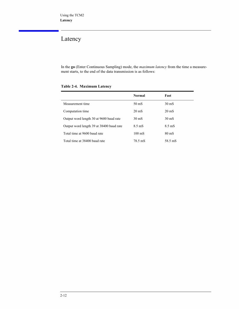
In the go (Enter Continuous Sampling) mode, the maximum latency from the time a measure-ment starts, to the end of the data transmission is as follows:
Table 2-4. Maximum Latency
Normal Fast
Measurement time 50 mS 30 mS
Computation time 20 mS 20 mS
Output word length 30 at 9600 baud rate 30 mS 30 mS
Output word length 39 at 38400 baud rate 8.5 mS 8.5 mS
Total time at 9600 baud rate 100 mS 80 mS
Total time at 38400 baud rate 78.5 mS 58.5 mS
2-12
Using the TCM2Magnetic Distortion Alarm
Magnetic Distortion Alarm
The TCM2’s magnetic distortion alarm indicates magnetic anomalies that can compromise com-pass and magnetometer accuracy. The process of user calibration (See “ User Calibration” on page 2-15) allows the TCM2 to measure the nominal local magnetic field. This field value is then stored as a reference. During continuous sampling, the TCM2 evaluates the quality of mag-netic environment by utilizing an algorithm that compares the instantaneous magnetic field information against the stored reference. If significant deviations are detected, the magnetic dis-tortion alarm error flag is raised (if enabled).
How to Use the Magnetic Distortion Alarm
To utilize the alarm, you must first perform a user calibration. Refer to “ User Calibration” on page 2-15. Next, the magnetic distortion alarm must be enabled by using the ed= (Enable Mag-netic Distortion Alarm) command. From this point on, TCM2 output of compass or magnetome-ter data will be flagged with the magnetic distortion alarm code if the distortion condition exists. See the discussion of TCM2 error codes in “Error Codes ” on page 2-6.
How to Interpret the Magnetic Distortion Alarm
The TCM2 raises the magnetic distortion alarm when it detects a local magnetic anomaly. Your system should consider compass and magnetometer outputs to be suspect when the alarm is raised. The alarm can indicate short-term disturbances; for example, if the TCM2 is placed next to a large source of ferrous metal, or if a nearby piece of electrical equipment is activated. The alarm can also indicate long term disturbances; if, for instance, the TCM2 has been reinstalled in a different system without recalibration in which case the TCM should be recalibrated.
2-13
Using the TCM2Pitch and Roll Output
Pitch and Roll Output
The TCM2 uses a fluid-filled tilt sensor to measure the orientation of the compass with respect to gravity. Since the compass also measures the complete magnetic field, the TCM2 can correct for the tilt of the compass to provide an accurate heading.The tilt sensor measures the angles between the compass Z axis and the gravity vector. This is a different set of angles than the pitch and roll angles as commonly used in an airplane. The pitch and roll of an airplane is usually defined as the angle rotated around an axis through the center of the fuselage; pitch is rotation around an axis through the center of the wings. These two rotations are independent of each other since the rotation axes rotate with the plane body. Because the tilt sensor uses gravity, it is really measuring rotations around the level Earth coor-dinate axes. Because these are fixed, and do not rotate with the body, the pitch and roll output by the TCM2 will act differently than the pitch and roll defined in an airplane.You can use the tilt data output by the TCM2 to calculate the orientation of the TCM2 with respect to the level Earth coordinate frame. Define a vector G that is perpendicular to the com-pass board (and therefore is parallel to the Z-axis of the compass.) The coordinates of G = (X, Y, Z) in the level Earth frame will be:
where P and R are the pitch and roll reported by the TCM2. The tilt range we specify for the TCM2 is the angle this G vector makes relative to gravity. This tilt sensor is accurate within this tilt range. The inclination of the compass relative to gravity, θ, can be easily calculated as:
,
where X, Y, and Z are the components of the G vector given above.The compass will only compensate for the tilt within specifications when the inclination is less than the TCM2 tilt range.
Z SQRT 1 P( )2tan R( )2tan+ +( )( ) 1–=
X Z tan(P)=
Y Z tan(R)=
θ arctangent X2 Y2+( ) Z2⁄( )=
2-14

Using the TCM2 User Calibration
User Calibration
All compasses can perform well in a controlled environment, where the ambient magnetic field consists solely of the earth’s field. In most practical applications, however, an electronic com-pass module will be mounted in a host system such as a vehicle that can contain large sources of local magnetic fields: ferrous metal chassis, transformer cores, electrical currents, and perma-nent magnets in electric motors. By performing the user calibration procedure, you allow the TCM2 to identify the major sources of these local magnetic anomalies and subsequently cancel out their effects when measuring the earth’s magnetic field for computing compass headings. When you perform the user calibration procedure, the TCM2 takes a series of magnetic field measurements. It analyzes these total field measurements in order to identify the components that are created by the earth’s field, which is the desired signal, from those components that are generated by the local environment, which we wish to subtract out. The end goal of the procedure for the TCM2 is to have an accurate measurement of the static three-dimensional magnetic field vector generated by its host system at its mounting location. This vector is subsequently subtracted out of run-time field measurement to yield the resultant earth’s field vector. One major benefit from the TCM2’s triaxial magnetometer/biaxial inclinometer system configu-ration is its ability to compensate for hard-iron effects in all orientations throughout its usable tilt range. As we have mentioned, a compass must measure the local field vector generated by the host system at its current position within the system in order to accurately calibrate. Because the TCM2’s magnetometer is strapped-down, or fixed with respect to its host system, this local field vector does not change as the host system’s attitude changes, allowing the TCM2 to accurately compensate in all pitch and roll orientations. Gimbaled fluxgates, for instance, are unable to pro-vide accurate calibration in non-level orientations because its magnetometers, being gimbaled, change position with respect to the host system as attitude changes. This presents a different local distortion field than that measured during calibration.
2-15

Using the TCM2 User Calibration
Automatic Calibration
The principal of automatic calibration is to correct for any deviations from the initial calibration corrections. The magnetic anomalies of a system can change over time. Hence, after initial cali-bration, you might need to recalibrate the system to get accurate compass data. The automatic calibration feature allows you to enable the TCM2 to automatically correct for magnetic anoma-lies in the system. Automatic calibration is not required for most purpose and better results will be obtained from rerunning the multipoint calibration. It continuously updates the estimated hard iron distortion vector. At 10 Hz, the response time of the TCM2 will not be affected even with automatic cali-bration enabled. However, if the TCM2 is sampling faster than 10 Hz and auto calibration is set, the real time response of the TCM2 is not fully maintained.
C A U T I O N This mode should be used with care, there are a number of environmental characteristics that lead to incorrect results. This mode should not be used in environments where there are many transient magnetic anomalies or the system has a continuous repetitive movement that does not cover much of a circle while pitching and/or rolling.
Automatic calibration should be enabled after multipoint calibration. The following commands are used to enable automatic calibration:
autocal=e !Enable automatic calibration
go !Run in this mode, take data points
h !Update the EEPROM with the newly computed
! hard iron distortion.
autocal=d ! Disable the autocal mode.
To check how well the automatic calibration improved the score, use the lc? (Last Calibration) command.
N O T E The EEPROM does not save the new autocal computed coefficients until the data acquisition is halted (h), if power is lost during autocal, before it is halted, the TCM2 will restart with the prior mpcal (Multipoint Calibration) values.
2-16
Using the TCM2 User Calibration
Soft Iron Effects
The TCM2 can calibrate for hard iron effects, or local fields that can be modeled as static fields such as those created by permanent magnets. Hard iron distortions are significant in most sys-tems. There is another class of soft iron effects that are created by the amplification of magnetic fields by highly permeable materials, such as ferrous metals. The TCM2 does not currently com-pensate for soft iron effects. Soft iron effects, however, are generally far weaker than hard iron effects in most systems, and can be more readily defeated by choosing a suitable location to mount your compass module. In some systems, however, it may be difficult to avoid large masses of ferrous metal that may create non-trivial soft iron effects, such as an armor plate in a tracked vehicle. In these instances, try to locate the module as far away from the ferrous metals as possible. Soft iron effects decrease with distance by an inverse square relation so even modest separation can be effective. The TCM2, does collect sufficient data to be mathematically capable of calibration for soft iron effects. Algorithms are currently being developed to implement a soft iron calibration in later models. If you do have soft iron effects from your system, contact PNI Corp. for the soft iron correction software that runs on your PC. The algorithm is too large to fit on to the current 8-bit microprocessor used on the TCM2, hence, the program allows for the algorithm to run on a PC and loads the coefficients into the EEPROM of the TCM2.
Other Limitations
As discussed, the TCM2 models local disturbances as a static magnetic vector contribution to the earth’s field. Any local fields, which are not static, will create errors. You cannot calibrate for anomalies that are not fixed with respect to the compass. For example, you may know that the TCM2 will be used in close proximity to other vehicles. You cannot calibrate for the effects of these other vehicles, as they will be moving with respect to the TCM2. This is a limitation universal to all compasses. However, the TCM2 does present a warning when such local distur-bances occur. See “Magnetic Distortion Alarm ” on page 2-13. Consider, therefore, the TCM2’s position relative to any potential sources of field that will not be static: magnetic cargo or payloads that may be placed in close proximity, fans or other electri-cal equipment that may be turned on and off, and so on. The TCM2 can calibrate for any environment that creates a magnetic field that does not exceed the dynamic range of its magnetometers.
2-17
Using the TCM2Calibration Procedures
Calibration Procedures
There are two basic operations related to user calibrations:
• Calibrating the TCM2 for the first time, or for a new installation.
• Updating the TCM2’s calibration.
There are two internal calibration routines available for calculating the effects of hard iron mag-netism on the compass.
• Multipoint Calibration
• CAL3
Multipoint is convenient for most users as it does not require any precision positioning. Depend-ing on your equipment configuration, you may find the alternative routine, CAL3, to provide an easier, accurate, and quicker method of measuring hard iron correction. Both calibration proce-dures are described below.You must be in Standby mode in order to issue calibration commands. The TCM2 cannot accept other commands during the calibration procedure.
2-18
Using the TCM2Calibration Procedures
Multipoint Calibration (mpcal)
Key Points for the MPCAL Routine
• Tilt as much as possible during the calibration. This allows the compass to take full advantage of the 3-axis magnetometer.
• Move slowly, take at least a minute to make a full circle. You are trying to get an even sam-pling of the magnetic field over as many headings and tilts as possible.
• If you get a poor calibration, clear it before making a new calibration.
• Pay attention to the score. A poor score is not good enough.
Procedure
1 Clear any previous calibration by sending cc.
2 Enable multipoint calibration by sending mpcal=e.
3 Put the TCM2 in continuous mode by sending go.
4 Turn the host system with the TCM2 installed around at least twice changing the pitch and roll as much as possible.
Each turn should take longer than 1 minute. The turn does not need to be a perfect circle. In the calibration mode, the TCM2 is trying to take as many different data points as possible to deter-mine the magnetic anomalies. The more pitch and roll points you give it, the better it is able to determine the vertical magnetic fields. If possible, apply as close to a ±90 ° pitch and ±90 ° roll. Doing so will improve the quality of the calibration. Do not worry about exceeding the range of the inclinometer.
5 Halt the TCM by sending h if halt=e; or h <return> if halt=d.
6 Check the calibration score by sending lc?.
• If the calibration score is not satisfactory, set the TCM in the go (Enter Continuous Sampling) mode and take more data points for 1 or 2 turns.
• If the score still does not improve much, disable multipoint calibration by sending mpcal=d, clear the last calibration by sending cc and rerunning the multipoint calibration mpcal=e.
The hard iron calibration algorithm uses a Kalman filtering algorithm. Hence it is best to slowly move the TCM2 during hard iron calibration.
Interpreting the Calibration Score
The TCM2 provides feedback on calibration through the calibration score, which has the follow-ing format: “...HnVnMn....” The first two numbers in the calibration score, HnVn, respectively describe the quality of the calibration for the horizontal component and vertical component of the host system’s local mag-netic field. Higher numbers reflect higher quality. The highest possible score is a “9”. The fac-tors that contribute to a good score for Hn and Vn are as follows:
• a good, magnetically quiet location was chosen for the user calibration procedure.
• the magnetic environment of the TCM2’s host is stable, there are no large sources of changing fields.
• the calibration data points included a change in system inclination to allow for proper mea-
2-19
Using the TCM2Calibration Procedures
surement of the horizontal and vertical field vectors.
• there are no significant soft-iron distortion effects.
The last number in the score, Mn.nn, describes the magnitude of local field generated by the host system. Larger numbers denote strong local fields. Small local fields are preferable, since less correction will be necessary, and they utilize less of the magnetometers’ dynamic range. A mag-nitude score greater than 30 indicates strong magnetic fields at the TCM2 location; you should consider alternative mounting locations. Any score less than 10 is very good. You can use the em=e (Enable Magnetometer Data for Output Word) command to find positions on your equip-ment with the least magnetic field. Refer to “Where to Install the TCM2” on page 1-7 for locat-ing the TCM2 away from local sources of changing magnetic fields.The calibration score values mostly provide a qualitative estimation. For example, a good score would be H9V9Mn.nn. A poor score as anything less than H9V9Mn.nn. A poor V score gen-erally indicates that you need to tilt more during the calibration. A poor H score indicates you did not turn two full circles or that you turned too quickly.
CAL3 Procedure
The CAL3 calibration requires you to take three measurements in three orientations. It is very important for the accuracy of the routine that the orientations be as exact as possible. Error in positioning will translate directly into errors in the hard iron calibration. The CAL3 calibration requires you to take one measurement, turn the system 180 ° exactly, take another measurement, turn the system upside-down exactly, and take a third measurement. The compass is taking two measurements on each axis with the directions reversed between them. The average of the two measurements is the hard iron vector that the TCM2 needs to correct.
N O T E Do not use the TCM2.exe program to run this calibration. Us a terminal program such as HyperTerminal instead.
Procedure
1 Position the system to start. See Figure 2-1.
2 Type CAL3 and press the keyboard’s Enter key.
The TCM2 will take a measurement and prompt you to turn the system 180 °. It is very impor-tant that this be as exact as possible. In general, this will require some sort of fixture to hold and position your sensor.
3 Turn the system exactly 180 ° and press the keyboard’s Space bar to continue. See Figure 2-2.
The TCM2 will take a measurement, you will be prompted to turn the system upside-down. It is very important that the Z-axis in the new position be exactly 180 ° from the original position.
4 Turn the system upside-down and press the keyboard’s Space bar to continue. See Figure 2-3.
The TCM2 will take the third measurement and calculate the hard iron correction.
2-20

Using the TCM2Calibration Procedures
Figure 2-1. Measurement 1
Figure 2-2. Measurement 2
Figure 2-3. Measurement 3
2-21

Using the TCM2Calibration Procedures
Temperature Sensor Calibration
The temperature sensor of the TCM2 can be easily calibrated if you can put the TCM2 in two environments with known temperatures. The TCM2 does not require temperature compensation for the inclinometer. To calibrate the temperature sensor of the TCM2 electronic compass module, perform the fol-lowing steps:
1 Send the following command to change the output word to the raw outputs (as opposed to the TCM2 standard output word or NMEA 0183 output word):
sdo=r
"r" stands for raw output.
N O T E All commands are followed by hitting the <Enter> key (which is the carriage return of the keyboard). When you ask for an update of the output word with the s? (Single Update of Output Word) or go Enter Continuous Sampling Mode, the TCM2 will output the raw pitch, roll, 3 axis magnetometers (X, Y, and Z) and temperature readings. For example:
$P0388,0077 R00B8,0320 X57D8,6D46 Y6680,5FB6 Z6328,631C T0269
2 Place the TCM2 in an environment with a known temperature in Celsius (T1). For example: T1 = 10 °C.
3 Query the TCM2 for an update of the output word with the s? (Single Update of Output Word) command. Write down the raw temperature reading (which is the number at the end following the letter "T" in the output word). This temperature is TR1.
4 Change temperature of the environment of the TCM2 to a new known temperature in Celsius (T2). For example, T2 = 20 °C.
5 Query the TCM2 for an update of the output word with the s? command. Write down the raw temperature reading. This is TR2.
6 Solve the following two equations for the temperature constants KT0 and KT1:
Then:
or
7 The coefficients must be scaled for use in the TCM2.
%KT0 = 10 * KT0
%KT1 = 40960 * KT1
T1 KT1 TR1 KT0+•=
T2 KT1 TR2 KT0+•=
T1 T2– KT1 TR1 KT1 TR2 KT0 KT0–+•–•=
T1 T2– KT1 TR1 TR2–( )•=
KT1 T1 T2–( )TR1 TR2–( )
--------------------------------=
KT0 T1 KT1 TR1•–= KT0 T2 KT1 TR2•–=
2-22

Using the TCM2Calibration Procedures
8 Send the TCM2 the commands to set the temperature coefficients as follows (assume %KT0=26.23749 and %KT1=0.02389):
C A U T I O N Failure to properly input the following command sequence could corrupt the TCM2 EEPROM. Never leave the *facal= command enabled (that is, facal=e).
9 Send the TCM2 the ax (Warm Reboot) command. On versions 2.77 and higher, give the TCM2 *faccal=e, then ax, and then *faccal=d.
The TCM2 should now use the coefficients KT0 and KT1 which you just stored. Calibration of the temperature sensor should be complete, and outputs of temperature in the TCM2 standard output word should be the correct temperature sensed by the sensor. To check that the TCM2 actually stored these coefficients, you can query the TCM2 what these coefficients are with the following commands:
10 Send the TCM2 the sdo=t command (the command to change the output word back to the standard TCM2 output word.
%KT0 26.23749=
%KT1 0.02389=
%KT0?
%KT1?
2-23

Using the TCM2Calibration Procedures
2-24
3
Command List Quick Reference 3-2Differences Between TCM2 Firmware Version 2.82 and 2.34A 3-4
Changes to the EEPROM 3-4Command List 3-5Request for Data Commands 3-6Action Commands 3-11User Configuration Parameter Commands 3-17
Programming Commands

Programming CommandsCommand List Quick Reference
Command List Quick Reference
Table 3-1. Command List
Command Description Page
Request for Data Commands
c? Compass Update page 3-6
i? Inclinometer Update page 3-7
lc? Query Last Calibration Score page 3-8
m? Magnetometer Update page 3-8
s? Single Update Output Word page 3-9
t? Temperature Update page 3-9
Action Commands
autocal Automatic Calibration page 3-11
ax Warm Reboot page 3-12
cc Clear Calibration Data page 3-12
factory Factory Settings page 3-13
go Enter Continuous Mode page 3-13
h Halt Continuous Sampling, Enter Standby page 3-14
halt= Enable single character halt page 3-14
mpcal Multipoint Calibration page 3-15
sleep Sleep Mode page 3-16
wake Wake Mode page 3-16
User Configuration Parameter Commands
%skip= Skip Measurements page 3-17
b= Set Baud Rate page 3-17
cclip= Set Clip Value page 3-18
clock= Set Clock Rate page 3-19
damping= Set Digital Damping page 3-19
ec= Enable Compass Data for Output Word page 3-20
3-2

Programming CommandsCommand List Quick Reference
ed= Enable Magnetic Distortion Alarm page 3-20
em= Enable Magnetometer Data for Output Word page 3-21
ep= Enable Pitch Data for Output Word page 3-21
er= Enable Roll Data for Output Word page 3-22
et= Enable Temperature Data for Output Word page 3-22
fast= Enable Fast Sampling page 3-23
ma= Select Magnetometer Output Option page 3-23
mag_dec= Set Declination Angle page 3-24
sao= Select Analog Output Mode page 3-25
sdo= Set RS232 Output Word Format page 3-25
seriallp= Low Power Serial Consumption page 3-26
sn= Select Magnetic or True North page 3-27
sp= Set Sampling Period Divisor page 3-28
timeconst= Set Time Constant for Digital Damping page 3-28
uc= Set Compass Units page 3-29
ui= Set Inclinometer Units page 3-29
ut= Set Temperature Units page 3-30
Table 3-1. Command List
Command Description Page
3-3

Programming CommandsDifferences Between TCM2 Firmware Version 2.82 and 2.34A
Differences Between TCM2 Firmware Version 2.82 and 2.34A
Firmware version 2.82 is backward compatible with the 2.34A version of the TCM2 firmware except for the following changes:
• The TCM2 takes about 430 mS to start up when power is first applied to the unit. Previously it took about 250 mS to start up.
• All parameters set by the user via the command set were immediately written to EEPROM. In version 2.82, most commands do not update the EEPROM. The new parameters are not up-dated until one of the following updating commands are issued. If the power was disconnected before the new parameters were updated by one of the updating commands, those new param-eters would be lost.
Changes to the EEPROM
The changes to the EEPROM are not visible to the user. Version 2.82 duplicates the factory cali-bration coefficients, user hardiron coefficients, and user configurations in two different memory locations of the EEPROM. Also, the factory calibration coefficients, user coefficients, and the user configuration parameters are all stored in separate banks of memory in the EEPROM. Changes were made to make the data in the EEPROM less susceptible to corruption.The EEPROM changes are as follows:
1 Changed from an 8 bit checksum to a 16 bit checksum.
2 The coefficients are stored in three different sections of the EEPROM. Each section can only be accessed if that section is enabled. The three sections are:
• Factory Calibration: If this section of the EEPROM is corrupt, error E400 will appear.• User Coefficient: The hardiron and softiron calibration coefficients will be stored here. If this
section of the EEPROM is corrupt, error E800 will appear.• User Configurations: All user set configurations will be saved in this section of the EE-
PROM. If this section is corrupt, error E800 will appear.
3 The three sections of the EEPROM are each backed up in a separate bank of EEPROM. The user correction and user configuration banks are updated each time a Write to EEPROM is done.
Table 6-2. Updating Commands
go cc
h save
ax mpcal=d
factory cal3
3-4
Programming CommandsCommand List
Command List
All of the TCM2 commands are summarized in a list in Appendix B, along with the default val-ues for all of the user parameters that are set when you receive the TCM2.
ctrl-e, ctrl-n (Special Commands)
The TCM2 ordinarily does not echo characters received over the RS232 interface. You may enable echo by typing <Ctrl> e or disable it by typing <Ctrl> n.
3-5
Programming CommandsRequest for Data Commands
Request for Data Commands
These commands are used to request data from the TCM2.
c? (Compass Update)
Description Samples the magnetometer and inclinometer sensors, then calculates and returns the compass heading. When in Standby mode (h) use this command to query the compass reading regardless of whether compass data has been selected for inclusion in the output word.
Syntax c?<cr>
Output when compass units are set to degrees:
$Cnnn.n[Ennn]*checksum<cr><lf>:<cr><lf>
when compass units are set to mils:
$Cnnn.n[Ennn]<cr><lf>:<cr><lf>
Resolution 0.1 ° or 2 mils
Valid Values 0 to 359.9 ° or, 0 to 6399 mils
Example If TCM2 is configured for degrees:
c?<cr>
$C255.5[Ennn]*checksum<cr><lf>:<cr><lf>
If TCM2 is configured for mils:
c?<cr>
$C4480[Ennn]*checksum<cr><lf>:<cr><lf>
Related Commands uc= (Set Compass Units)ec= (Compass Data Enable)
3-6
Programming CommandsRequest for Data Commands
i? (Inclinometer Update)
Description Samples and returns the pitch and roll inclinometer data. When in Standby mode (h) use this command to query the inclinometer readings regardless of whether inclinometer data has been selected for inclusion in the output word.
Syntax i?<cr>
Output When the inclinometer units are set to degrees:
$P(-)nn.nR(-)nn.n[Ennn]*checksum<cr><lf>:<cr><lf>
When inclinometer units set to mils:
$P(-)nnnR(-)nnn[Ennn]*checksum<cr><lf>:<cr><lf>
Resolution 0.1° or 2 mils
Valid Values
Example i?<cr>
$P-30.0R-20.1[Ennn]*checksum<cr><lf>:<cr><lf>
Related Commands ep= (Enable Pitch)er= (Enable Roll)
Degree Mils
0 to ±20.0 ° 0 to ±355.5 mils
0 to +55 ° 0 to +973.5 mils
0 to +80 ° 0 to +1421.6 mils
3-7
Programming CommandsRequest for Data Commands
lc? (Query Last Calibration Score)
Description Reports the score generated by the last calibration procedure executed, as stored in EEPROM. Use this command to recall the quality of the last calibration procedure. For a complete descrip-tion of user calibration, Refer to “ User Calibration” on page 2-15.
Syntax lc?<cr>
Output: HnVnMn.nn<cr><lf>
Valid Values 0-9 for H and V
Example lc?<cr>
H7V8M8.00<cr><lf> !An example of a poor score
Related Commands mpcal (Multipoint Calibration)autocal (Auto Calibration)
m? (Magnetometer Update)
Description: Samples and returns the X, Y, and Z axes of magnetometer data. When in Standby mode (h) use this command to query the magnetometer readings regardless of whether magnetometer data has been selected for inclusion in the output word.
Syntax m?<cr>
Output $X(-)nn.nnY(-)nn.nnZ(-)nn.nn[Ennn]<cr><lf>:<cr><lf>
Resolution 0.01 µT
Valid Values 0 to ±79.9 µT
Example m?<cr>
$X25.00Y10.50Z-03.00[Ennn]*checksum<cr><lf>:<cr><lf>
Related Commands em= (Enable Magnetometer)
3-8

Programming CommandsRequest for Data Commands
s? (Single Update of Output Word)
Description Transmits the output word you specified. Refer to “Data Transmission” on page 2-5 for a full discussion of output word formatting. This command can only be used in the Standby (h) mode. The Select RS232 Output Word Format (sdo=) command allows you to select between NMEA or TCM2 Standard formats for the output word. If TCM2 Standard output is selected, only those data parameters that are enabled (with ec, ep, er, em, et) will be output.
N O T E In Standby mode (h), the TCM2 sensors are idle. When this command is issued in Standby mode, the TCM2 will first sample its sensors before transmitting the output word.
Syntax s?<cr>
Output Refer to “RS232 Data Output Word” on page 2-2 for a full description of the output word for-mats.
Example s?<cr>
$C328.3P28.4R-12.4X55.1Y12.3Z-18.4T22.3[Ennn]*check-sum<cr><lf>:<cr><lf>
Related Commands sdo= (Select RS232 Output Word Format)ec= (Enable Compass Data for Output Word)ep= (Enable Pitch Data for Output Word)er= (Enable Roll Data for Output Word)em= (Enable Magnetometer for Output Word)et= (Enable Temperature Data for Output Word)
t? (Temperature Update)
Description Sample and return the ambient temperature. When in the Standby mode (h) use this command to query the temperature readings regardless of whether temperature data has been selected for inclusion in the output word.
Syntax t?<cr>
Output When the units are set to Celsius:
$T(-)nnn.n[Ennn]*checksum<cr><lf>:<cr><lf>
When units set to Fahrenheit:
$T(-)nnn[Ennn]*checksum<cr><lf>:<cr><lf>
Resolution 0.5 °C or 1 °F
3-9

Programming CommandsRequest for Data Commands
Valid Values
Example t?<cr>
$T25.5[Ennn]*checksum<cr><lf>:<cr><lf>
Related Commands et= (Enable Temperature)ut= (Set Temperature Units)
Celsius Fahrenheit
25.0 to 100.0 °C -13 to 212 °F
3-10
Programming CommandsAction Commands
Action Commands
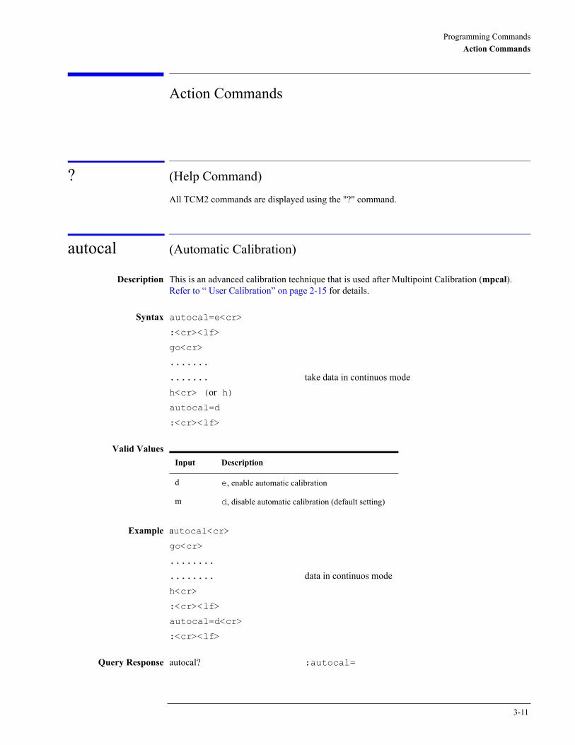
? (Help Command)
All TCM2 commands are displayed using the "?" command.
autocal (Automatic Calibration)
Description This is an advanced calibration technique that is used after Multipoint Calibration (mpcal). Refer to “ User Calibration” on page 2-15 for details.
Syntax autocal=e<cr>
:<cr><lf>
go<cr>
.......
....... take data in continuos modeh<cr> (or h)autocal=d
:<cr><lf>
Valid Values
Example autocal<cr>go<cr>
........
........ data in continuos modeh<cr>
:<cr><lf>
autocal=d<cr>
:<cr><lf>
Query Response autocal? :autocal=
Input Description
d e, enable automatic calibration
m d, disable automatic calibration (default setting)
3-11
Programming CommandsAction Commands
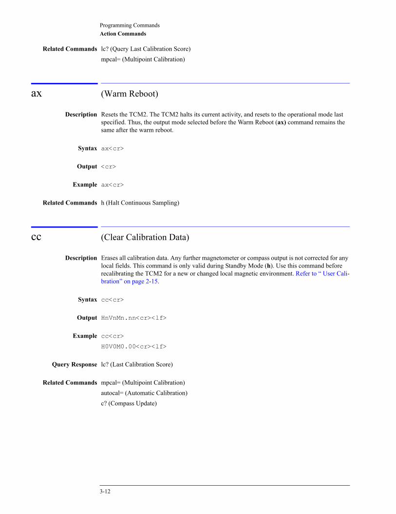
Related Commands lc? (Query Last Calibration Score)mpcal= (Multipoint Calibration)
ax (Warm Reboot)
Description Resets the TCM2. The TCM2 halts its current activity, and resets to the operational mode last specified. Thus, the output mode selected before the Warm Reboot (ax) command remains the same after the warm reboot.
Syntax ax<cr>
Output <cr>
Example ax<cr>
Related Commands h (Halt Continuous Sampling)
cc (Clear Calibration Data)
Description Erases all calibration data. Any further magnetometer or compass output is not corrected for any local fields. This command is only valid during Standby Mode (h). Use this command before recalibrating the TCM2 for a new or changed local magnetic environment. Refer to “ User Cali-bration” on page 2-15.
Syntax cc<cr>
Output HnVnMn.nn<cr><lf>
Example cc<cr>
H0V0M0.00<cr><lf>
Query Response lc? (Last Calibration Score)
Related Commands mpcal= (Multipoint Calibration)autocal= (Automatic Calibration)c? (Compass Update)
3-12
Programming CommandsAction Commands
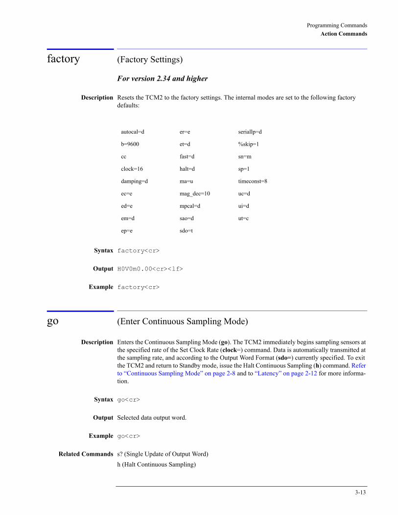
factory (Factory Settings)
For version 2.34 and higher
Description Resets the TCM2 to the factory settings. The internal modes are set to the following factory defaults:
Syntax factory<cr>
Output H0V0m0.00<cr><lf>
Example factory<cr>
go (Enter Continuous Sampling Mode)
Description Enters the Continuous Sampling Mode (go). The TCM2 immediately begins sampling sensors at the specified rate of the Set Clock Rate (clock=) command. Data is automatically transmitted at the sampling rate, and according to the Output Word Format (sdo=) currently specified. To exit the TCM2 and return to Standby mode, issue the Halt Continuous Sampling (h) command. Refer to “Continuous Sampling Mode” on page 2-8 and to “Latency” on page 2-12 for more informa-tion.
Syntax go<cr>
Output Selected data output word.
Example go<cr>
Related Commands s? (Single Update of Output Word)h (Halt Continuous Sampling)
autocal=d er=e seriallp=d
b=9600 et=d %skip=1
cc fast=d sn=m
clock=16 halt=d sp=1
damping=d ma=u timeconst=8
ec=e mag_dec=10 uc=d
ed=e mpcal=d ui=d
em=d sao=d ut=c
ep=e sdo=t
3-13

Programming CommandsAction Commands
h (Halt Continuous Sampling, Enter Standby)
Description Exits Continuous Sampling Mode (go) and enters Standby mode (h). If this command is received while the TCM2 is transmitting an output word, the remainder of the output word will be sent before the TCM2 changes modes.
Syntax h<cr>
Output :[Ennn]<cr><lf>
Related Commands go (Enter Continuous Sampling Mode)halt= (Enable Single Character Halt)
halt= (Enable Single Character Halt)
For versions 2.82 and higher
Description In the previous versions of the TCM2, during Enter Continuous Sampling Mode (go), some-times the halt command was not accepted. This is because interrupts are disabled during incli-nometer readings to synchronize the sensor readings. Interrupts are off for several milliseconds, potentially permitting a receive buffer overflow. To correct this, the halt command during go mode has optionally been made a single character command using the halt=e command. Refer to “Standby Mode” on page 2-8 for more information.
Syntax halt=d<cr>
Output :[Ennn]<cr><lf>
Valid Values
Query Response halt? :halt=
Related Commands go (Enter Continuous Sampling Mode)
Input Description
e halt=e
d h, cr command for halting the output (default setting)
3-14

Programming CommandsAction Commands
mpcal (Multipoint Calibration)
Description Initiates a multipoint calibration. This command is only valid during Enter Continuous Sam-pling Mode (go). The TCM2 samples its sensors and adds the data point to the current set of cal-ibration data. For a full description of the user calibration procedure, Refer to “ User Calibration” on page 2-15.
Syntax mpcal=e<cr>
:<cr><lf>
go<cr>
.......
...... take data in continuos modeh<cr> (or h):<cr><lf>
mpcal=d<cr>
Valid Values
Output HnVnMn.nn<cr><lf>
The TCM2 only reports a calibration score after it has been put in Standby mode (h).
Example mpcal=e<cr>
:<cr><lf>
go<cr>
........
....... take data in continuos modeh<cr>:<cr><lf>
mpcal=d<cr>
H4V3M5.00:<cr><lf> (This is an example of a poor score)
Query Response mpcal? :mpcal=
Related Commands lc? (Query Last Calibration Score)autocal= (Automatic Calibration)
Input Description
e e, enable multipoint calibration
d d, disable multipoint calibration (default setting)
3-15

Programming CommandsAction Commands
sleep (Sleep Mode)
Description Enters the sleep mode of operation. This command turns off the internal clocks and the RS-232 chip.
Syntax sleep<cr>
Output
Example
Related Commands wake (Wake Mode)
wake (Wake Mode)
Description Enters the wake mode of operation.To wake the TCM2, a falling edge on the int2 (interrupt 2) pin of the processor is required. This is achieved by connecting pin 6 of the TCM2 connector to the RTS pin (pin 4 on a DB25 and pin 7 on a DB9) of the COM port.A sample wake.c program is provided on the TCM2.exe diskette.
Syntax wake<cr>
Output
Example
Related Commands sleep (Sleep Mode)
3-16
Programming CommandsUser Configuration Parameter Commands
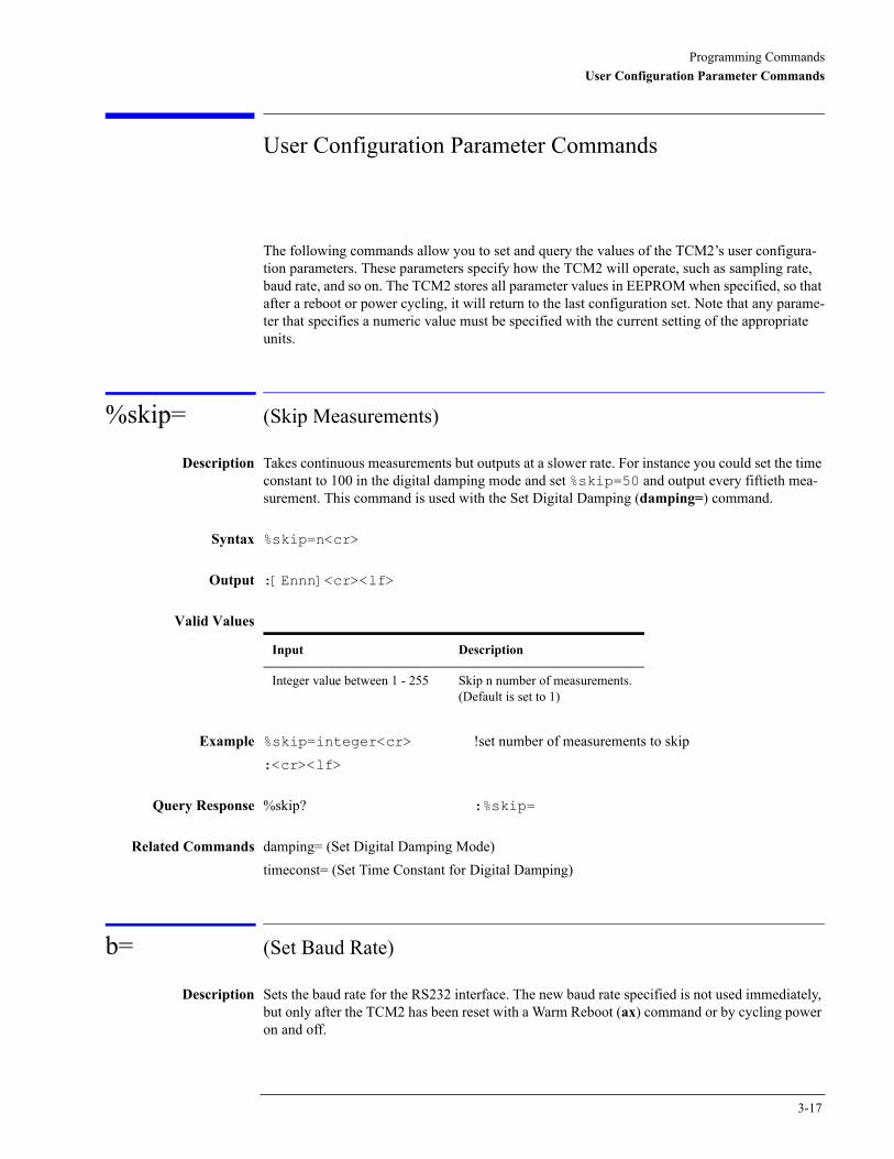
User Configuration Parameter Commands
The following commands allow you to set and query the values of the TCM2’s user configura-tion parameters. These parameters specify how the TCM2 will operate, such as sampling rate, baud rate, and so on. The TCM2 stores all parameter values in EEPROM when specified, so that after a reboot or power cycling, it will return to the last configuration set. Note that any parame-ter that specifies a numeric value must be specified with the current setting of the appropriate units.
%skip= (Skip Measurements)
Description Takes continuous measurements but outputs at a slower rate. For instance you could set the time constant to 100 in the digital damping mode and set %skip=50 and output every fiftieth mea-surement. This command is used with the Set Digital Damping (damping=) command.
Syntax %skip=n<cr>
Output :[Ennn]<cr><lf>
Valid Values
Example %skip=integer<cr> !set number of measurements to skip:<cr><lf>
Query Response %skip? :%skip=
Related Commands damping= (Set Digital Damping Mode)timeconst= (Set Time Constant for Digital Damping)
b= (Set Baud Rate)
Description Sets the baud rate for the RS232 interface. The new baud rate specified is not used immediately, but only after the TCM2 has been reset with a Warm Reboot (ax) command or by cycling power on and off.
Input Description
Integer value between 1 - 255 Skip n number of measurements. (Default is set to 1)
3-17
Programming CommandsUser Configuration Parameter Commands
N O T E The TCM2.EXE program cannot use the 38400 baud rate. Do not use TCM2.exe to change the baud rate to 38400. If the TCM2 is set to 38400 (b=7), the TCM2.exe program will not be able to communicate with the PC.
The 38400 baud rate can be used with other terminal programs that support this rate. Examples of these programs are TELIX, PROCOMM and the telephone icon in the Accessories window of Windows. When using a terminal program you will need to set the correct baud rate, no parity, 1 stop bit, 8 bits and the COM port.
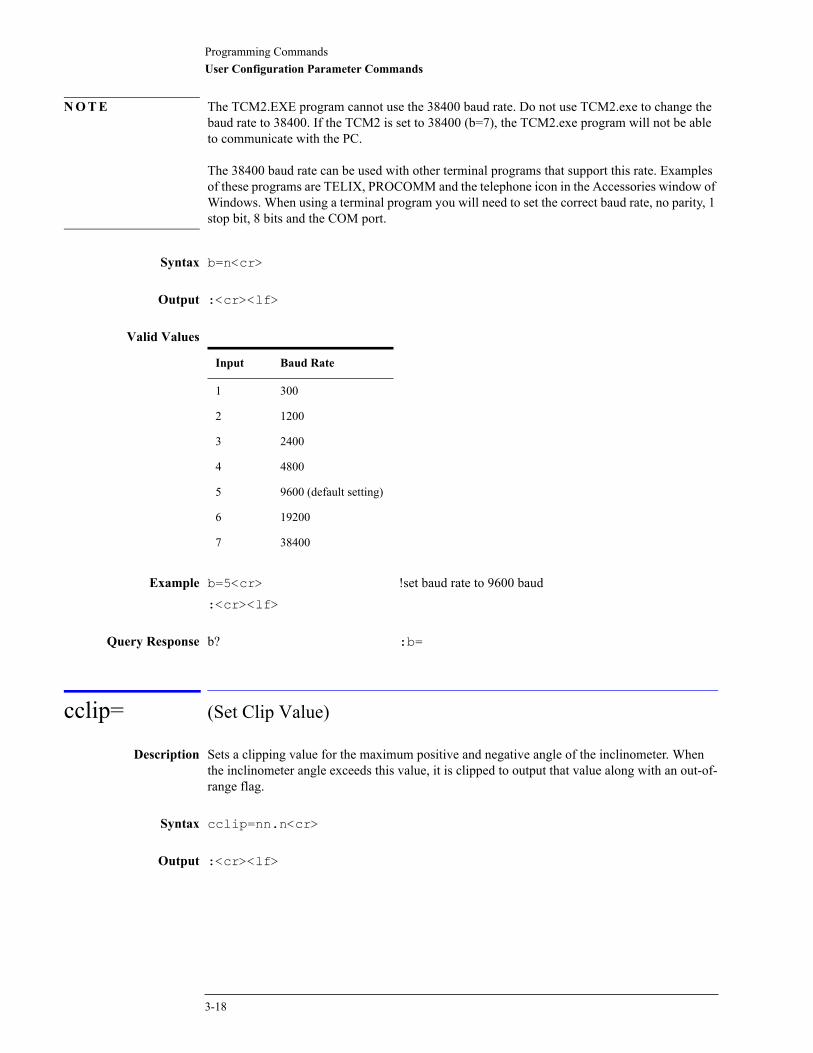
Syntax b=n<cr>
Output :<cr><lf>
Valid Values
Example b=5<cr> !set baud rate to 9600 baud:<cr><lf>
Query Response b? :b=
cclip= (Set Clip Value)
Description Sets a clipping value for the maximum positive and negative angle of the inclinometer. When the inclinometer angle exceeds this value, it is clipped to output that value along with an out-of-range flag.
Syntax cclip=nn.n<cr>
Output :<cr><lf>
Input Baud Rate
1 300
2 1200
3 2400
4 4800
5 9600 (default setting)
6 19200
7 38400
3-18

Programming CommandsUser Configuration Parameter Commands
Valid Values
Example cclip=nn.n<cr> !set the value for the clip angle:<cr><lf>
Query Response cclip? :cclip=
clock= (Set Clock Rate)
Description Allows you to have precise control of the clock rate. The ability to sample at the higher speeds must be matched with the amount of data being output at each sample. At 9600 baud, each char-acter requires about 1 mS to output, so at 30 Hz, the most that can be output is 30 characters, which is not enough for all data outputs to be enabled in the output word.
Syntax clock=nn.nn<cr>
Output :[Ennn]<cr><lf>
Valid Values From 5 Hz to 40 Hz. 5 is equal to 5 Hz, 10 is equal to 10 Hz, and so on. (Default is set to 16 Hz)
Example clock=30<cr> !set clock rate to 30 Hz:<cr><lf>
Query Response clock? :clock=
Related Commands fast= (Enable Fast Sampling)sp= (Set Sampling Period Divisor)
damping= (Set Digital Damping)
Description Enables or disables filtering of the output. The damping uses an IIR filter on the measured data. It is only enabled during Enter Continuous Sampling Mode (go). Refer to “Digital Damping” on page 2-10 for more information.
Syntax damping=n<cr>
Output :[Ennn]<cr><lf>
Input Description
Positive floating point minus the range of the inclinometer.
Clip the reading of the inclinometer at this value. (Default is 1 degree)
3-19
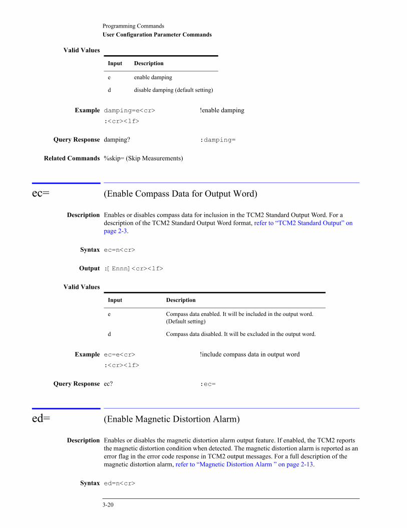
Programming CommandsUser Configuration Parameter Commands
Valid Values
Example damping=e<cr> !enable damping:<cr><lf>
Query Response damping? :damping=
Related Commands %skip= (Skip Measurements)
ec= (Enable Compass Data for Output Word)
Description Enables or disables compass data for inclusion in the TCM2 Standard Output Word. For a description of the TCM2 Standard Output Word format, refer to “TCM2 Standard Output” on page 2-3.
Syntax ec=n<cr>
Output :[Ennn]<cr><lf>
Valid Values
Example ec=e<cr> !include compass data in output word:<cr><lf>
Query Response ec? :ec=
ed= (Enable Magnetic Distortion Alarm)
Description Enables or disables the magnetic distortion alarm output feature. If enabled, the TCM2 reports the magnetic distortion condition when detected. The magnetic distortion alarm is reported as an error flag in the error code response in TCM2 output messages. For a full description of the magnetic distortion alarm, refer to “Magnetic Distortion Alarm ” on page 2-13.
Syntax ed=n<cr>
Input Description
e enable damping
d disable damping (default setting)
Input Description
e Compass data enabled. It will be included in the output word. (Default setting)
d Compass data disabled. It will be excluded in the output word.
3-20
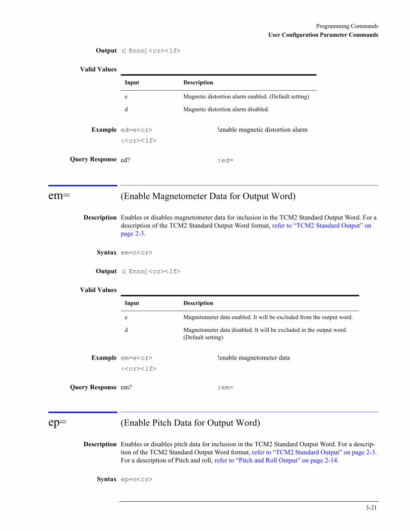
Programming CommandsUser Configuration Parameter Commands
Output :[Ennn]<cr><lf>
Valid Values
Example ed=e<cr> !enable magnetic distortion alarm:<cr><lf>
Query Response ed? :ed=
em= (Enable Magnetometer Data for Output Word)
Description Enables or disables magnetometer data for inclusion in the TCM2 Standard Output Word. For a description of the TCM2 Standard Output Word format, refer to “TCM2 Standard Output” on page 2-3.
Syntax em=n<cr>
Output :[Ennn]<cr><lf>
Valid Values
Example em=e<cr> !enable magnetometer data :<cr><lf>
Query Response em? :em=
ep= (Enable Pitch Data for Output Word)
Description Enables or disables pitch data for inclusion in the TCM2 Standard Output Word. For a descrip-tion of the TCM2 Standard Output Word format, refer to “TCM2 Standard Output” on page 2-3. For a description of Pitch and roll, refer to “Pitch and Roll Output” on page 2-14.
Syntax ep=n<cr>
Input Description
e Magnetic distortion alarm enabled. (Default setting)
d Magnetic distortion alarm disabled.
Input Description
e Magnetometer data enabled. It will be excluded from the output word.
d Magnetometer data disabled. It will be excluded in the output word. (Default setting)
3-21
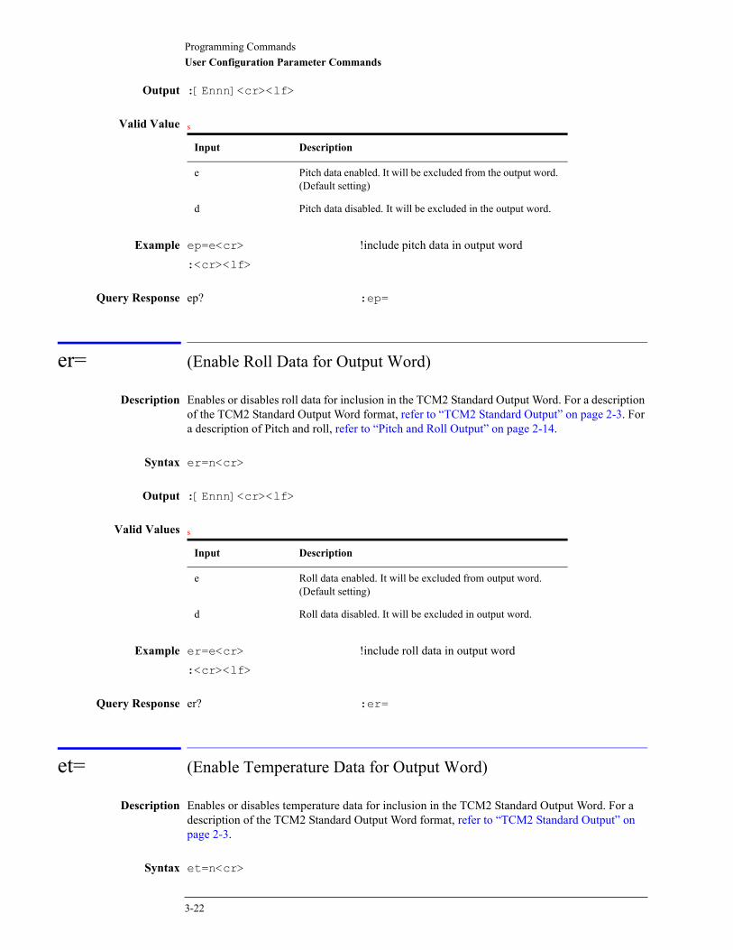
Programming CommandsUser Configuration Parameter Commands
Output :[Ennn]<cr><lf>
Valid Value s
Example ep=e<cr> !include pitch data in output word:<cr><lf>
Query Response ep? :ep=
er= (Enable Roll Data for Output Word)
Description Enables or disables roll data for inclusion in the TCM2 Standard Output Word. For a description of the TCM2 Standard Output Word format, refer to “TCM2 Standard Output” on page 2-3. For a description of Pitch and roll, refer to “Pitch and Roll Output” on page 2-14.
Syntax er=n<cr>
Output :[Ennn]<cr><lf>
Valid Values s
Example er=e<cr> !include roll data in output word:<cr><lf>
Query Response er? :er=
et= (Enable Temperature Data for Output Word)
Description Enables or disables temperature data for inclusion in the TCM2 Standard Output Word. For a description of the TCM2 Standard Output Word format, refer to “TCM2 Standard Output” on page 2-3.
Syntax et=n<cr>
Input Description
e Pitch data enabled. It will be excluded from the output word. (Default setting)
d Pitch data disabled. It will be excluded in the output word.
Input Description
e Roll data enabled. It will be excluded from output word. (Default setting)
d Roll data disabled. It will be excluded in output word.
3-22
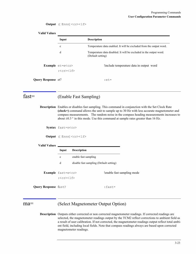
Programming CommandsUser Configuration Parameter Commands
Output :[Ennn]<cr><lf>
Valid Values
Example et=e<cr> !include temperature data in output word:<cr><lf>
Query Response et? :et=
fast= (Enable Fast Sampling)
Description Enables or disables fast sampling. This command in conjunction with the Set Clock Rate (clock=) command allows the unit to sample up to 30 Hz with less accurate magnetometer and compass measurements. The random noise in the compass heading measurements increases to about ±0.3 ° in this mode. Use this command at sample rates greater than 16 Hz.
Syntax fast=n<cr>
Output :[Ennn]<cr><lf>
Valid Values
Example fast=e<cr> !enable fast sampling mode:<cr><lf>
Query Response fast? :fast=
ma= (Select Magnetometer Output Option)
Description Outputs either corrected or non corrected magnetometer readings. If corrected readings are selected, the magnetometer readings output by the TCM2 reflect corrections to ambient field as a result of user calibration. If not corrected, the magnetometer readings output reflect total ambi-ent field, including local fields. Note that compass readings always are based upon corrected magnetometer readings.
Input Description
e Temperature data enabled. It will be excluded from the output word.
d Temperature data disabled. It will be excluded in the output word. (Default setting)
Input Description
e enable fast sampling
d disable fast sampling (Default setting)
3-23

Programming CommandsUser Configuration Parameter Commands
Syntax ma=n<cr>
Output :[Ennn]<cr><lf>
Valid Values
Example ma=c<cr> !corrected magnetometer readings :<cr><lf>
Query Response ma? :ma=
mag_dec= (Set Declination Angle)
For version 2.34 and higher
Description Sets the magnetic declination angle in degrees. Sets the declination offset for a reading of True North. Based on the setting of the Compass Units (uc) command. Positive declination is easterly declination and negative is westerly declination. This is not applied until True North is set to true.
Declination, also called magnetic variation, is the difference between true and magnetic north, relative to a point on the earth. It is measured in degrees east or west of true north. Correcting for declination is accomplished by storing the correct declination angle, and then changing the heading reference from magnetic north to true north. Declination angles vary throughout the world, and change very slowly over time. For the greatest possible accuracy, go to the National Geophysical Data Center web page below to get the declination angle based on your latitude and longitude: http://www.ngdc.noaa.gov/cgi-bin/seg/gmag/fldsnth1.pl
Syntax mag_dec=nn.n<cr>
Output :[Ennn]<cr><lf>
Valid Values
Example mag_dec=17.2 !sets the declination angle to 17.2 degrees:<cr><lf>
Query Response mag_dec? :mag_dec=
Input Description
c Choose corrected magnetometer readings.
u Choose non corrected magnetometer readings. (Default setting)
Input Description
nn.n declination angle in degrees
(The default value is set to 10)
3-24

Programming CommandsUser Configuration Parameter Commands
Related Commands sn= (Select Magnetic or True North)
sao= (Select Analog Output Mode)
Description Sets the mode for analog output. For a full description of analog output modes, refer to “Analog Outputs” on page 2-9.
Syntax sao=n<cr>
Output :[Ennn]<cr><lf>
Valid Values
Example sao=l<cr> !set analog output mode to linear :<cr><lf>
Query Response sao? :sao=
sdo= (Set RS232 Output Word Format)
Description Sets the output word format to be used in response to the Single Update Output Word (sdo?) command and in Continuous Output Mode (go). For a full description of TCM2 output words, refer to “RS232 Data Output Word” on page 2-2.
Syntax sdo=n<cr>
Output :[Ennn]<cr><lf>
Valid Values
Example sdo=t<cr> !output word format to TCM2 standard:<cr><lf>
Input Description
d Analog output disabled. (Default setting)
l Linear analog output enabled.
Q Quadrature analog output enabled.
Input Description
t standard TCM2 output word (Default setting)
r raw data
3-25
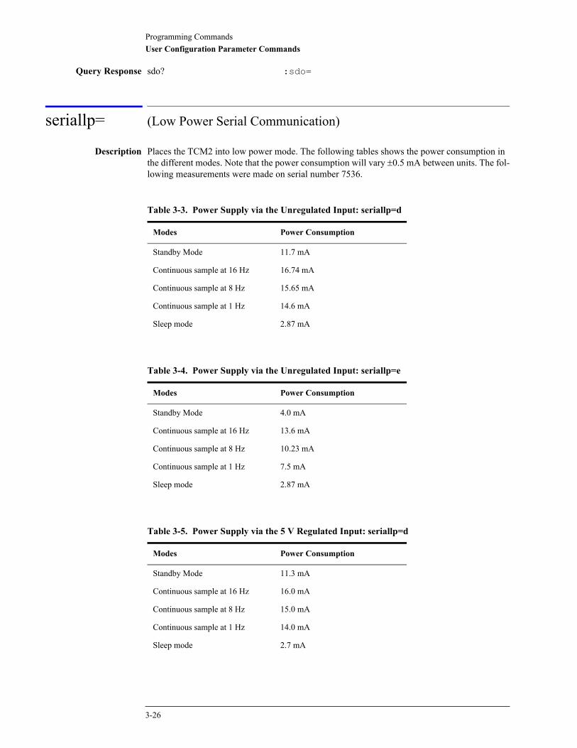
Programming CommandsUser Configuration Parameter Commands
Query Response sdo? :sdo=
seriallp= (Low Power Serial Communication)
Description Places the TCM2 into low power mode. The following tables shows the power consumption in the different modes. Note that the power consumption will vary ±0.5 mA between units. The fol-lowing measurements were made on serial number 7536.
Table 3-3. Power Supply via the Unregulated Input: seriallp=d
Modes Power Consumption
Standby Mode 11.7 mA
Continuous sample at 16 Hz 16.74 mA
Continuous sample at 8 Hz 15.65 mA
Continuous sample at 1 Hz 14.6 mA
Sleep mode 2.87 mA
Table 3-4. Power Supply via the Unregulated Input: seriallp=e
Modes Power Consumption
Standby Mode 4.0 mA
Continuous sample at 16 Hz 13.6 mA
Continuous sample at 8 Hz 10.23 mA
Continuous sample at 1 Hz 7.5 mA
Sleep mode 2.87 mA
Table 3-5. Power Supply via the 5 V Regulated Input: seriallp=d
Modes Power Consumption
Standby Mode 11.3 mA
Continuous sample at 16 Hz 16.0 mA
Continuous sample at 8 Hz 15.0 mA
Continuous sample at 1 Hz 14.0 mA
Sleep mode 2.7 mA
3-26
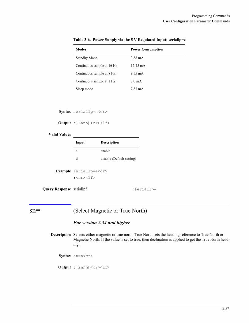
Programming CommandsUser Configuration Parameter Commands
Syntax seriallp=n<cr>
Output :[Ennn]<cr><lf>
Valid Values
Example seriallp=e<cr>
:<cr><lf>
Query Response seriallp? :seriallp=
sn= (Select Magnetic or True North)
For version 2.34 and higher
Description Selects either magnetic or true north. True North sets the heading reference to True North or Magnetic North. If the value is set to true, then declination is applied to get the True North head-ing.
Syntax sn=n<cr>
Output :[Ennn]<cr><lf>
Table 3-6. Power Supply via the 5 V Regulated Input: seriallp=e
Modes Power Consumption
Standby Mode 3.88 mA
Continuous sample at 16 Hz 12.45 mA
Continuous sample at 8 Hz 9.55 mA
Continuous sample at 1 Hz 7.0 mA
Sleep mode 2.87 mA
Input Description
e enable
d disable (Default setting)
3-27

Programming CommandsUser Configuration Parameter Commands
Valid Values
Example sn=t<cr> !the declination angle set with mag_dec is added to the!computed heading
:<cr><lf>
Query Response sn? :sn=
Related Commands mag_dec= (Set Declination Angle)
sp= (Set Sampling Period Divisor)
Description Divides the clock rate set by Set Clock Rate (clock=). For the TCM2, this command is meant to be used in conjunction with the clock= command to set the sampling period below 5 Hz. In the TCM1, this command was used to divide down the 8 Hz sampling rate. It can be used the same way in the TCM2 if the clock rate is set to 8 Hz.
Syntax sp=nnn<cr>
Output :[Ennn]<cr><lf>
Valid Values
Example sp=5<cr>
:<cr><lf>
Query Response sp? :sp=
timeconst= (Set Time Constant for Digital Damping)
Description This command is used with the digital damping command. It sets the time constant to nn sam-ples for the digital damping. Refer to “damping=” on page 3-19.
Syntax timeconst=n<cr>
Input Description
t true north (Default setting)
m magnetic north
Input Description
1 to 5 Sample every second sample of the clock rate. (Default setting is 1)
3-28
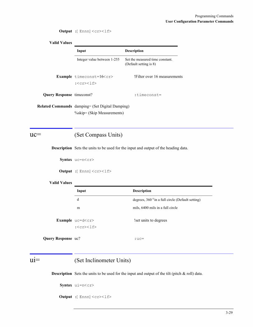
Programming CommandsUser Configuration Parameter Commands
Output :[Ennn]<cr><lf>
Valid Values
Example timeconst=16<cr> !Filter over 16 measurements:<cr><lf>
Query Response timeconst? :timeconst=
Related Commands damping= (Set Digital Damping)%skip= (Skip Measurements)
uc= (Set Compass Units)
Description Sets the units to be used for the input and output of the heading data.
Syntax uc=n<cr>
Output :[Ennn]<cr><lf>
Valid Values
Example uc=d<cr> !set units to degrees:<cr><lf>
Query Response uc? :uc=
ui= (Set Inclinometer Units)
Description Sets the units to be used for the input and output of the tilt (pitch & roll) data.
Syntax ui=n<cr>
Output :[Ennn]<cr><lf>
Input Description
Integer value between 1-255 Set the measured time constant. (Default setting is 8)
Input Description
d degrees, 360 °in a full circle (Default setting)
m mils, 6400 mils in a full circle
3-29
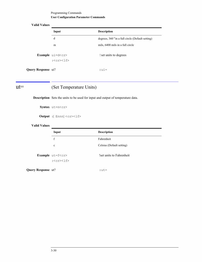
Programming CommandsUser Configuration Parameter Commands
Valid Values
Example ui=d<cr> !set units to degrees:<cr><lf>
Query Response ui? :ui=
ut= (Set Temperature Units)
Description Sets the units to be used for input and output of temperature data.
Syntax ut=n<cr>
Output :[Ennn]<cr><lf>
Valid Values
Example ut=f<cr> !set units to Fahrenheit:<cr><lf>
Query Response ut? :ut=
Input Description
d degrees, 360 °in a full circle (Default setting)
m mils, 6400 mils in a full circle
Input Description
f Fahrenheit
c Celsius (Default setting)
3-30

4
Trouble-Shooting the TCM2 4-2Limitations of the Inclinometer 4-6
Troubleshooting
TroubleshootingTrouble-Shooting the TCM2
Trouble-Shooting the TCM2
When I connect the TCM2 to my PC, there is no response from the TCM2• Make sure that you are giving the TCM2 the correct power, refer to “Electrical Connections”
on page 1-4 for proper connection of power, ground, TXD, RXD, and data ground.
• The TCM2 is defaulted to h (standby) mode. To enable the TCM2 either type the go (Enter Continuous Sampling) command or select the start continuous sampling button in the TCM2.exe program. This button is located at the top middle position on the TCM2.exe dis-play.
• With the TCM2.EXE program (or any terminal program you use), the program must be set to the correct COM port and baud rate that the TCM2 is currently using. The TCM2.EXE pro-gram default is COM2. For COM1, type TCM2 1 when you launch the program to select the COM1 port or use the set Program i/o parameters... button to select the COM port and reset the TCM2.
• When you change the baud rate, the TCM2 does not start using the new baud rate until after an ax (Warm Reboot) command or save (Save Settings) command has been sent, followed by cycling the power off and on again. When cycling the power after the save command, make sure a ":" is returned from the TCM2 before cycling power off. If power is removed during a write to the EEPROM, it can get corrupted.
• If you change the baud rate to 38400 using the TCM2.EXE program and then cannot commu-nicate with the TCM2, you will have to find a computer and terminal program (such as TELIX or PROCOMM) that can communicate at 38400. Then you can set the TCM2 to the desired baud rate. There is no other way to change the baud rate of the TCM2 from 38400 after it has been changed; that is, there is no hard reset which will change the baud rate.
N O T E The TCM2.EXE program CAN ONLY use baud rates up to 19200. Although it can give the command to change the baud rate to a faster baud rate, the TCM2.EXE will not be able to communicate at a baud rate greater than 19200.
• The TCM2 needs to be set to the same baud rate as the communication program. If you do not know the baud rate of the TCM2, try using COM1 and each baud rate. If none of those com-binations work, try using COM2 and each baud rate.
The calibration score looks good, but when I move the TCM2, the output of head-ing only changes a few degrees when I turn the TCM2 through 360 °
• Α good score is H9V9Mnn.n where nn.n < 30.0 µT. Any value of the H and V that is less than 9 is not a good score.
• Your previous calibration may have been "bad" and you may not have cleared the previous calibration data (the cc command) before starting the new calibration.
• You may have softiron. The Multipoint and CAL3 calibration procedures remove the effects of hardiron, but will not account for softiron. Softiron effect is a magnetic anomaly vector that changes as you rotate it around the earth's field. This is a much more complicated anomaly to fix. Refer to “Soft Iron Effects” on page 2-17 for more information.
4-2

TroubleshootingTrouble-Shooting the TCM2
The heading from the TCM2 jumps around or just seems wrong• First look for any error code. Refer to “Error Codes ” on page 2-6 for detailed error code de-
scriptions.
• The heading of the TCM2 is calculated using the 3 magnetometer outputs and 2 axis inclinom-eter. It is important to identify the sensor that is noisy. Send the following commands to enable all the sensor outputs:
em=e !magnetometer data enabled
ep=e !enable pitch data for output word
er=e !enable roll data for output word
ec=e !enable compass data for output word
go !enter continuous sampling mode
Check the values of pitch, roll, and the X, Y and Z magnetometers. Check if any of the sensors are noisy. If the magnetometers are noisy, look for external sources of magnetic fields that could be changing. If the inclinometer is noisy, check for vibration.
• Check for any distortion sensed by the TCM2 by checking if there is an error flag (“Ennn”) in the output word. If there is an error flag including “E001” or “E004”, then you may not have cleared the calibration data (cc) before a new calibration. If the error flag is then “E400”, then there is a serious EEPROM error, and you must contact PNI Corp. to determine how to restore the EEPROM coefficients.
• Check whether the three magnetometer sensors are working by giving the following com-mands:
sdo=r !set data output to raw
s? !get a single update of the output word
The first line of the output will look like this:
$Pnnnn,nnnn Rnnnn,nnnn Xnnnn, nnnn Ynnnn,nnnn Znnnn,nnnn Tnnnn<cr><lf>:<cr><lf>
If both numbers (nnnn,nnnn) after X, Y or Z are 0000 (for example, X 0000,0000), then that sen-sor or the drive circuitry is malfunctioning. Please contact PNI Corp.
• To put the TCM2 back in normal operating mode, give the sdo=t (Set RS232 Output Word Format) command for the Standard TCM2 output word or sdo=n command for the NMEA 0183 output word.
The pitch or roll output does not change• First make sure that the inclinometer is not set to clip at any particular angle with the “cclip?”
command. Either set the clip to 0 (cclip=0) or set the clip to a value that is greater than the tilt range of your system (for example, cclip=19 °).
• Make sure that you are giving the TCM2 power correctly, refer to “Electrical Connections” on page 1-4.
• Check the voltage level applied to the TCM2. The sensor accuracy depends on the present voltage level and current level.
4-3
TroubleshootingTrouble-Shooting the TCM2
The output rate is slower than it should be• The output rate is a function of a number of commands: clock= (Set Clock Rate), sp= (Set
Sampling Period Divisor) and %skip= (Skip Measurements) commands. The sampling rate is equal to the clock divided by the sampling period (clock/sp). The TCM2 uses the %skip value even when damping is not enabled. The actual output rate is equal to the sampling rate (clock/sp) divided by the number of samples that the TCM2 is to skip (%skip). Therefore, the output rate is clock/sp/%skip. If you are not using the digital damping feature, then use the %skip=0 command so that the TCM2 does not skip any outputs.
1 There is an error message (“Ennn”) in the output word.
• Refer to “Error Codes ” on page 2-6 for descriptions of each error code and the most likely cause for the error.
2 When the host system moves, the fluid in the inclinometer sloshes around and gives inaccurate tilt, which results in inaccurate heading calculations.
• If the TCM2 will experience significant vibration or sloshing, there are two ways to dampen the effect. First, try the “digital damping” function, refer to “Digital Damping” on page 2-10. Second, a more viscous fluid can be used in the inclinometer. You must contact PNI Corp. for pricing and ordering a TCM2 with a different inclinometer.
3 I want to see if the compass is accurate.
• Try this simple functional test.
1 Set the TCM2 on a flat surface and mark its location.
2 Take a reading of the heading.
3 Turn the compass 180 ° and take another reading.
Try this at about 4 different orientations (for example, starting at 0 °, 45 °, 90 °, and 135 °) The compass should read a difference of 180 ° between pairs of readings. Watch out for nearby metal; most tables, for example, have metal parts that distort the magnetic field and will make the compass give inaccurate readings.
4-4
TroubleshootingTrouble-Shooting the TCM2
What else should I not do?• Do not remove power before a command is complete. Power must not be removed from the
TCM2 while the TCM2 is executing a command. Doing this can erase the EEPROM because the EEPROM is not write-protected at that time. You must wait for the TCM2 complete the command. For example, when you send a command em=d (disable magnetometers), it will return a “:” to indicate it is finished.
• Do not set the baud rate too fast. With the TCM2.EXE program (or any terminal program you use), the program must be set to the correct COM port and baud rate that the TCM2 is currently using. The TCM2.EXE program default is COM2. For COM1, type TCM2 1 when you launch the program to select the COM1 port or use the set Program i/o parameters... button to select the COM port and reset the TCM2.
Also, you can overflow the serial input buffer of your computer if the b= (Set Baud Rate) and sp= (Set Sampling Period Divisor) are set too fast. For example, many 486 computers cannot process the serial input if the sample rate is 30 Hz and the baud rate is 38400.
• Do not use steel parts (or other parts which can be magnetized) near the TCM2. Steel and other parts can be magnetized, meaning that the material will take on a different magnetic charge than the charge it had during calibration. These parts can be magnetized by moving a magnet (or any source of a magnetic field) near them. If you must use a certain part with these prop-erties, then your customers should be warned to keep the product away from sources of mag-netic fields which could magnetize that part. They should also look for the E001 error. Auto calibration function of the TCM2 can be used for these situations. Auto calibration will try to adjust the hardiron calibration coefficients to reflect the change but if the magnetization is too large, a full multipoint calibration will be necessary.
• Do not put a magnet on the TCM2 compass. Some components on the board can become mag-netized if exposed to a strong magnetic field.
• We recommend conformal coat if the board will be exposed to moisture or sources of contam-ination.
4-5

TroubleshootingLimitations of the Inclinometer
Limitations of the Inclinometer
While the TCM2 electronic compass can handle many rugged environments and dynamic situa-tions, there are limits. The majority of the limits result from the inclinometer (the tilt sensor), which is filled with an electrolytic fluid.
Acceleration
When the TCM2 is in acceleration, the fluid in the tilt sensor will be thrown up against the side of its bubble. Examples of situations with acceleration include banking turns of an airplane and take off of an airplane. The tilt sensor will measure the angle of the fluid as the tilt of the system because it cannot distinguish between acceleration and tilt. The error from this measurement will result in an error in the calculated heading. Therefore, the host system has to be able to tol-erate inaccurate heading when acceleration is present. A formula which relates acceleration to the error in tilt is as follows:
Acceleration = 5* gravity * tangent(A)
where A is the error measured in degrees (solve for A to get the error). This equation only applies to the standard 20% dampened tilt sensor fluid used on the TCM2. The scale factor 5 will be different for different types of tilt sensor fluids. For example, with acceleration of about 0.84 m/sec*sec and gravitational force of 9.8 m/sec*sec, then the error in tilt will be about 1 °. The related error in heading will be from 1° to about 8°, depending on where the compass is on earth. Here in Mountain View, CA, the error in heading for 1° of tilt will be about +/-2.1 °.
Settling Time
After a sudden change in heading, the settling time for the inclinometer (which is the limiting factor) is approximately 300 mS.
Shock
The limiting factor for surviving shock is the inclinometer. The vendor of the inclinometer pro-vided the only test results we have for the inclinometer: it was shown to withstand 20 g for 11 mS and to withstand 11 g for 18 mS. We do not have any test results for any other situations.
Vibration
The natural frequency of the standard fluid in the inclinometer is approximately 20 Hz. If the system has frequencies that are within a few hertz of this, the tilt sensor will give inaccurate readings, which means that the heading will also be inaccurate. If your application has frequen-cies in this range, contact PNI Corp. to discuss using a different fluid in the inclinometer.
4-6
5
Specifications 5-2Heading and Tilt Specifications 5-2Magnetic Field Specifications for the TCM2-20, TCM2-50, and the Magnetometer Only 5-2General Specifications 5-3Assembly Views 5-33-Foot Cable 5-6Optional 6-Foot Cable 5-8
Performance Specification
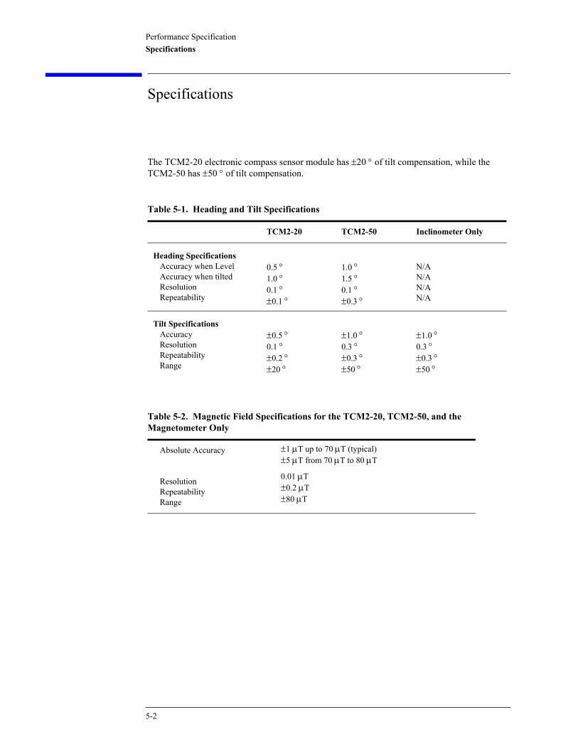
Performance SpecificationSpecifications
Specifications
The TCM2-20 electronic compass sensor module has ±20 ° of tilt compensation, while the TCM2-50 has ±50 ° of tilt compensation.
Table 5-1. Heading and Tilt Specifications
TCM2-20 TCM2-50 Inclinometer Only
Heading SpecificationsAccuracy when LevelAccuracy when tiltedResolutionRepeatability
0.5 ° 1.0 ° 0.1 °±0.1 °
1.0 ° 1.5 ° 0.1 °±0.3 °
N/AN/AN/AN/A
Tilt SpecificationsAccuracyResolutionRepeatabilityRange
±0.5 °0.1 °±0.2 °±20 °
±1.0 °0.3 °±0.3 °±50 °
±1.0 °0.3 °±0.3 °±50 °
Table 5-2. Magnetic Field Specifications for the TCM2-20, TCM2-50, and the Magnetometer Only
Absolute Accuracy
ResolutionRepeatabilityRange
±1 µT up to 70 µT (typical)±5 µT from 70 µT to 80 µT
0.01 µT±0.2 µT±80 µT
5-2
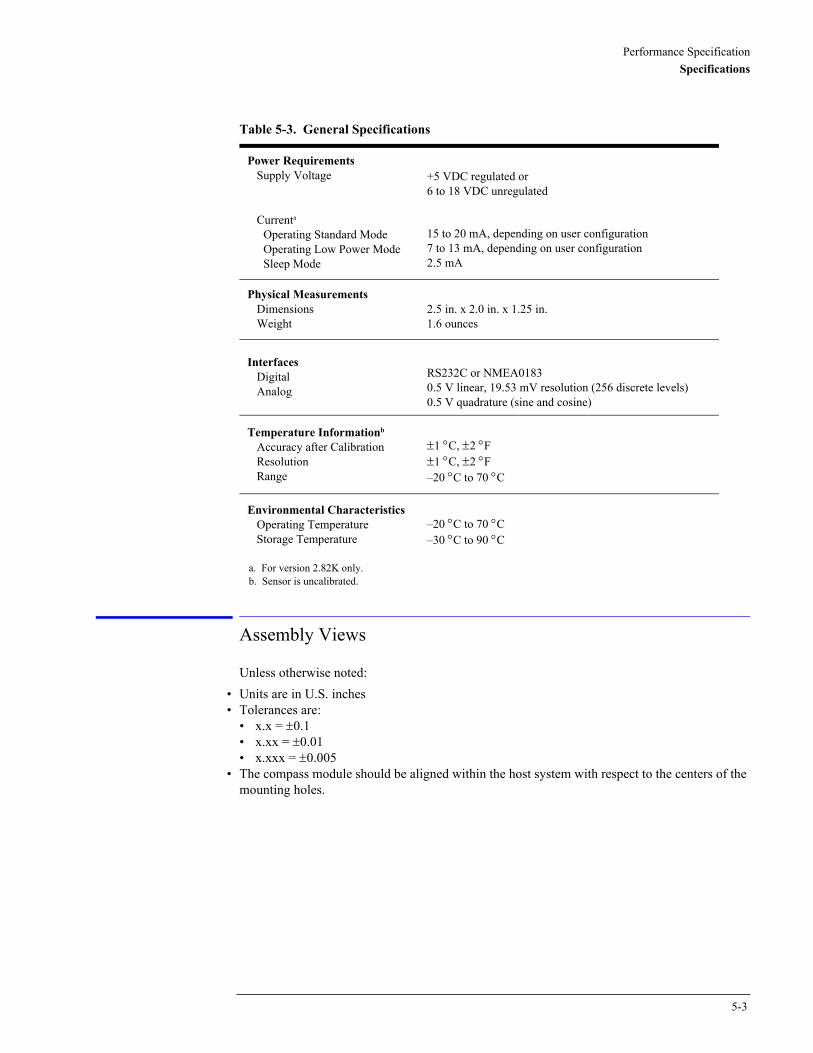
Performance SpecificationSpecifications
Assembly Views
Unless otherwise noted:• Units are in U.S. inches• Tolerances are:
• x.x = ±0.1• x.xx = ±0.01• x.xxx = ±0.005
• The compass module should be aligned within the host system with respect to the centers of the mounting holes.
Table 5-3. General Specifications
Power RequirementsSupply Voltage
Currenta
Operating Standard ModeOperating Low Power ModeSleep Mode
a. For version 2.82K only.
+5 VDC regulated or6 to 18 VDC unregulated
15 to 20 mA, depending on user configuration7 to 13 mA, depending on user configuration2.5 mA
Physical MeasurementsDimensionsWeight
2.5 in. x 2.0 in. x 1.25 in.1.6 ounces
InterfacesDigitalAnalog
RS232C or NMEA01830.5 V linear, 19.53 mV resolution (256 discrete levels)0.5 V quadrature (sine and cosine)
Temperature Informationb
Accuracy after CalibrationResolutionRange
b. Sensor is uncalibrated.
±1 °C, ±2 °F±1 °C, ±2 °F–20 °C to 70 °C
Environmental CharacteristicsOperating TemperatureStorage Temperature
–20 °C to 70 °C–30 °C to 90 °C
5-3
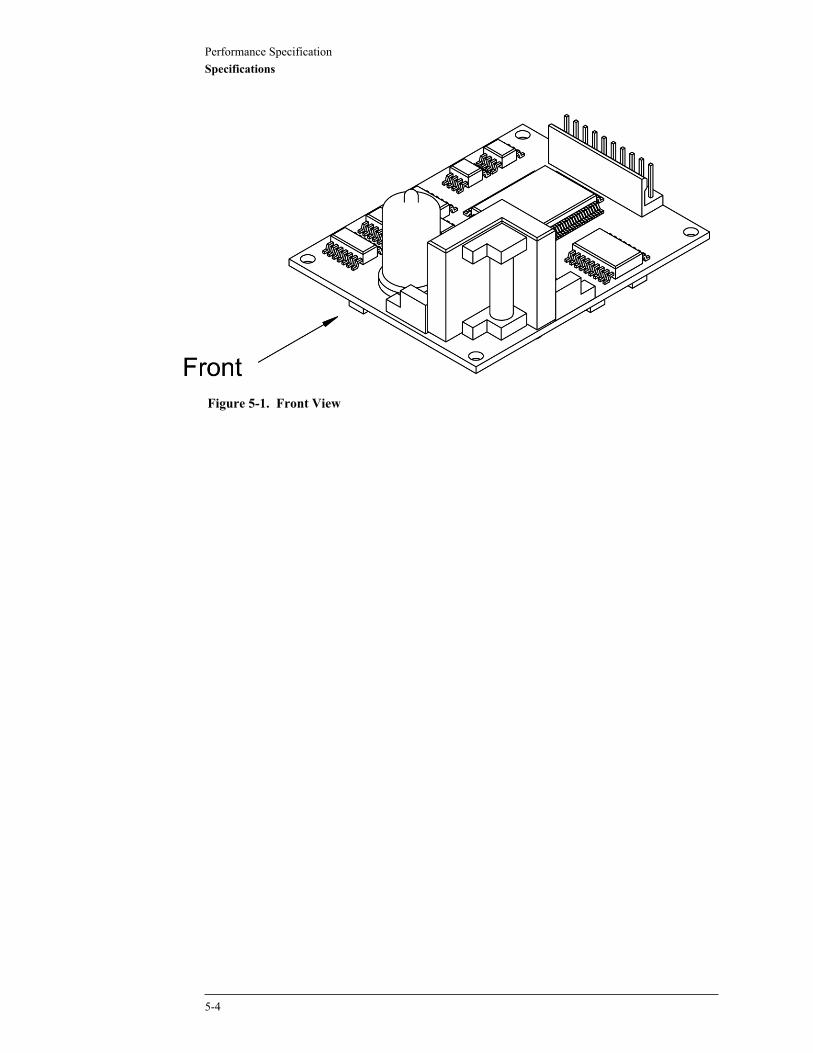
Performance SpecificationSpecifications
Figure 5-1. Front View
5-4
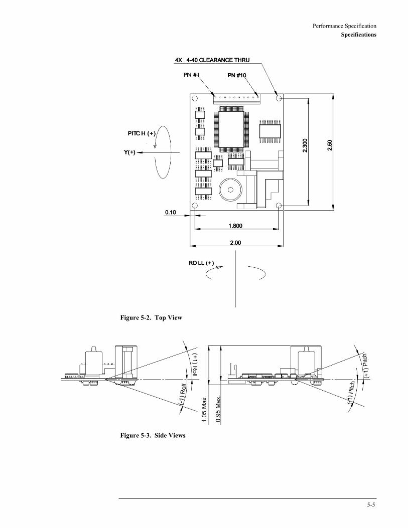
Performance SpecificationSpecifications
Figure 5-2. Top View
Figure 5-3. Side Views
5-5
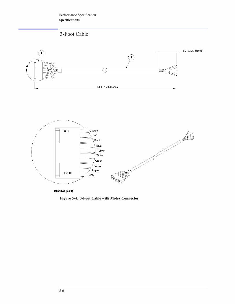
Performance SpecificationSpecifications
3-Foot Cable
Figure 5-4. 3-Foot Cable with Molex Connector
5-6

Performance SpecificationSpecifications
Table 5-4. Molex Connector Pin Description
Pin Wire Description
1 Orange Vsupply (5VDC ±5%)
2 Red Vsupply (6 - 18 VDC)
3 Black GND (power)
4 Blue RXD (RS-232)
5 Yellow TXD (RS-232)
6 White Mouse Input (not used)
7 Green GND (data)
8 Brown Analog Output 2
9 Purple Analog Output
10 Gray GND (data)
5-7
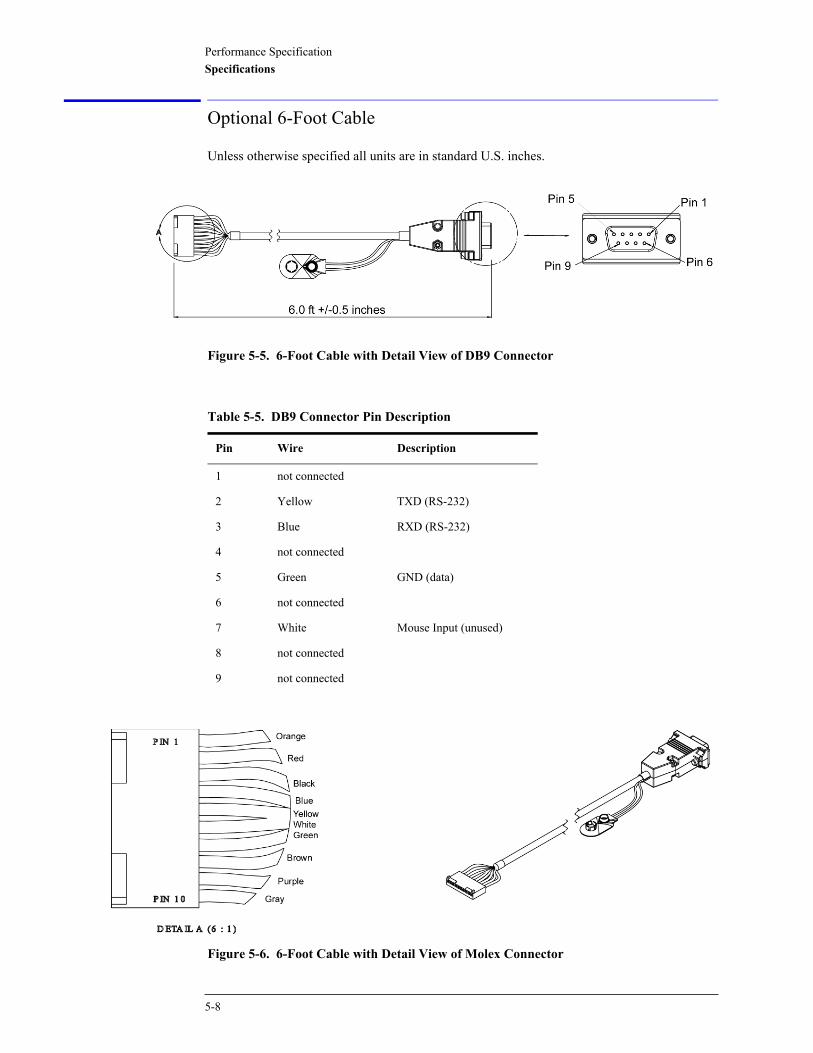
Performance SpecificationSpecifications
Optional 6-Foot Cable
Unless otherwise specified all units are in standard U.S. inches.
Figure 5-5. 6-Foot Cable with Detail View of DB9 Connector
Figure 5-6. 6-Foot Cable with Detail View of Molex Connector
Table 5-5. DB9 Connector Pin Description
Pin Wire Description
1 not connected
2 Yellow TXD (RS-232)
3 Blue RXD (RS-232)
4 not connected
5 Green GND (data)
6 not connected
7 White Mouse Input (unused)
8 not connected
9 not connected
5-8
Performance SpecificationSpecifications
Table 5-6. Molex Connector Pin Description
Pin Wire Description
1 Orange Vsupply (5VDC ±5%)
2 Red Vsupply (6 - 18 VDC)
3 Black GND (power)
4 Blue RXD (RS-232)
5 Yellow TXD (RS-232)
6 White Mouse Input (not used)
7 Green GND (data)
8 Brown Analog Output 2
9 Purple Analog Output
10 Gray GND (data)
5-9

Performance SpecificationSpecifications
5-10