Pneumatic systems - vacuum technology Vacuum … Generators_B... · Convum B Vacuum Generators...
60
Convum B Vacuum Generators Pneumatic systems - vacuum technology Pneumatic systems - vacuum technology Convum Vacuum Generators Convum Vacuum Generators Vacuum Generators Vacuum Generators FLUIDTECHNIK BOHEMIA s. r. o. Olomoucká 87 tel : 548 213 233 - 235 CZ-627 00 Brno fax : 548 213 238 http://www.fluidbohemia.cz brno@fluidbohemia.cz Section B
Transcript of Pneumatic systems - vacuum technology Vacuum … Generators_B... · Convum B Vacuum Generators...

Convum
B
Vacuum Generators
Pneumatic systems - vacuum technologyPneumatic systems - vacuum technology
Convum Vacuum GeneratorsConvum Vacuum Generators
Vacuum GeneratorsVacuum Generators
FLUIDTECHNIK BOHEMIA s. r. o.Olomoucká 87 tel : 548 213 233 - 235CZ-627 00 Brno fax : 548 213 238 http://www.fl uidbohemia.cz brno@fl uidbohemia.cz
Section B

118 04.10
www.parker.com/euro_pneumatic
Vacuum Generators Index
Technical Information How to select a Vacuum Generator. 120-123
MCA Venturi Generator for inline use or in combination with 124-127TYS level compensators.
CV Venturi Generator, precision manufactured for long life. 128-131External valving is required for operation.
CV-CK Venturi Generator with adjustable open contact 132-135switch for vacuum confirmation.
CV-VR Venturi Generator with blow-off reservoir. 136-139Blow-off release occurs automatically when theair supply valve interrupts the air supply.
MC2 Sub compact venturi generator with valving to 140-147control vacuum and blow-off release.Includes filter, silencer, and sensor porting.
CVK Venturi Generator for large flow rates with valving 148-155to minimize response time of the vacuum and blow-off release.Air-economizing features available. Includes filter, silencer,and sensor porting.
CVX-0260 Normally Closed vacuum venturi with a vacuum controlled 156-161E-Stop function. Large flow rates with valvingto minimize response time of the vacuum and blow-off release.Air-economizing features available. Includes filter, silencer,and sensor porting.
CEK Normally Closed vacuum venturi with a valve controlled 162-167E-Stop function. Large flow rates with valvingto minimize response time of the vacuum and blow-off release.Air-economizing features available. Includes filter, silencer,and sensor porting.

119 04.10
www.parker.com/euro_pneumatic
B
Vacuum Generators Index
P5V-GA Basic Generator 168-171
P5V-GWV Basic Generator 172-173with holding valveand release valve

120 04.10
www.parker.com/euro_pneumatic
Principle of Venturi VacuumA vacuum generator is a single stage venturi that createshigh vacuum with fast response using compressed air.
The ability to control this performance renders thistechnology as an excellent solution for factory automation.
In principle, compressed air is throttled as the air exits thenozzle and is discharged into the diffuser. This increasedvelocity of air lowers the pressure in the diffusion chamber.The volume of air within the closed vacuum system flows intothe low pressure area of the diffusion chamber and isexhausted thru the diffuser. This effect increases the vacuumlevel and evacuates most of the air within the closed vacuumsystem at supersonic speeds.
Additional Advantages toVenturi Generators• No Moving Components
• Low Maintenance
• Long Life
• Responsive
• Physically Small
• Cost Effective
Applying the Venturi GeneratorThere are two basic approaches when designing a vacuumsystem with venturi generators.
1. Design a system with basic venturi generators andindividual components to support the vacuum circuit.
Technical Information
2. Design a system with all of the supporting componentsintegrated into the venturi generator.
There are several advantages to an integrated venturisystem. The response time of the vacuum and blow-offfunctions are greatly reduced compared to basic venturigenerators, the installation time is also reduced which makesthis a cost effective system and the compact size allows theintegrated unit to be close to the suction cup.
Venturi Generator with Safety CircuitsWhen designing a vacuum system that requires a NormallyOpen circuit or E-Stop circuits to avoid any hazard during apower failure, consider the circuits below and on the followingpage.
Blow-off FlowAdjustment Sensor
Filter
CheckValve
Venturi
Normally ClosedBlow-off Pilot Valve
Normally ClosedVacuum Pilot Valve
Cup
Nozzle DiffuserDiffusion Chamber
Inlet Pressure
VacuumFlow
Exhaust
Blow-off FlowAdjustment Sensor
Filter
Venturi
Normally ClosedBlow-off Pilot Valve
Normally ClosedVacuum Pilot Valve
Normally OpenMaster Valve
Normally ClosedMaster Valve
CheckValve
Cup
Venturi
Cup
Normally ClosedAir Supply
Filter
Sensor

121 04.10
www.parker.com/euro_pneumatic
B
Technical Information
Valve Controlled E-Stop Circuit
Vacuum Controlled E-Stop Circuit
The Venturi with a Closed SystemFirst, let us understand how a venturi performs with a closedsystem. A closed vacuum system has a volume of air withinall the components between the vacuum port of the venturiand the suction cup. The venturi’s ability to evacuate thisvolume of air when the suction cup forms a seal on thesurface, creates the pressure differential required to forcethe suction cup onto the product.
The evacuated air creates a lower air pressure within theclosed vacuum system, causing the atmospheric pressure toapply a uniform force on the surface of the cup. This holdingforce is proportional to the difference in pressures and areaof the suction cup.
Selecting the Appropriate Supply ValveIf a basic venturi generator is selected, correct sizing of theair supply valve and supply line are critical to theperformance of the unit.
If pressure drops occur due to other pneumatic componentsor a manifold venturi system, it may be necessary toincrease the valve and / or supply line tubing I.D.
Selecting the Nozzle Diameter withReference to Suction Cup DiameterAs a general guide, for most non-porous vacuumapplications, the nozzle diameter can be selected based onthe suction cup diameter previously determined in Section A.
Designing a system with a single suction cup dedicated to asingle vacuum generator is ideal, however, it may not alwaysbe practical. It is recommended that the sum of the areas ofmultiple cups dedicated to a single venturi do not exceed thearea of the diameter of the single suction cups shown above.
Nozzle Maximum Suction Cup DiameterDiameter [mm]0,5 mm 201,0 mm 501,5 mm 602,0 mm 1202,5 mm 1503,0 mm 200
PFG Cup
E-StopValve
AirEconomizing
Valve
CheckValve
Sensor
VenturiN.C. MasterValve
N.C. MasterValve
Blow-offPilotValve
Filter
FlowControl
PFG Cup
Sensor
Venturi
N.C. MasterValve
N.C. MasterValve
Filter
FlowControl
VacuumPilotValve
E-stop System
Blow-offPilotValve
CheckValve
Nozzle Minimum Tube I.D.Diameter [mm] Flow [Cv]0,5 mm 4 0,161,0 mm 4 0,161,5 mm 6 0,3792,0 mm 8 0,652,5 mm 8 0,953,0 mm 10 1,35

122 04.10
www.parker.com/euro_pneumatic
RT = ( VD / C )1/a
RT(sec) = time for attaining vacuum (vacuum response time)
C = constant relative to vacuum degree
a = index relative to different types of the CONVUM
VD = Volume of air to be displaced in liters
VD = 0,780 x ID2 (mm) x L(m) /1000 + PV (n)
PV = Pad volume in liters n = Number of pads
Nozzle Vac, Flow CaØ [l / min] 55% Vacuum 90% Vacuum
05HS 6 0,03 1,02
05LS 9 0,11 1,06
07HS 11 0,06 1,02
07LS 19 0,31 1,02
09HS 15 0,07 1,09
09LS 21 0,37 1,09
10HS 27 0,12 1,09
10LS 36 0,25 1,09
15HS 63 0,25 1,00
15LS 95 0,74 1,09
20HS 110 0,62 1,09
20LS 165 1,00 1,09
25HS 160 0,69 1,00
25LS 250 3,27 1,00
30AHS 225 0,97 1,00
30ALS 350 4,88 1,00
EXAMPLE: Calculate the response time of a Convum generator with a specific nozzle diameter and specific volume of air(VD) to be displaced from the vacuum system.
25HS Nozzle Diameter = 2,5 mm, Vacuum Flow 160 l/min, 90% VacuumTube ID = 10 mm, Tube Length = 3 m, Pad = PBG-150 mm = 0,26 L
“C” value of 25HS = 0,69 (Constant derived from tests)
“a” value of 25HS = 1 (Constant derived from tests)
PV = 0,26 l n = 1
VD = 0,780 x (10 mm)2 x (3 meters / 1000) + 0,26 (1) = 0,494 l
RT = (0,494/0,69)(1/1) = 0,71 sec.
Technical Information
With minimal leakage in a closed system, most vacuumsources can achieve adequate vacuum levels to sufficientlytransfer product. The response time is the time required toevacuate the air out of a closed vacuum system. This isimportant to the operation of the system, which will vary by
Calculating the Response Time ofVacuum Generators
the generator nozzle diameter and the total volume of air tobe evacuated from the system. The response time (RT)calculation below is derived from actual test data relative tothe rated vacuum flow rates of the Convum generators.Therefore, calculations must be in metric units of measure.Charts with metric conversions are provided on page 7.
Therefore, it would require 0,71 seconds to evacuate 0,26liters of air to a vacuum level of 0,92 bar.

123 04.10
www.parker.com/euro_pneumatic
B
Technical Information

124 04.10
www.parker.com/euro_pneumatic
Vacuum Generators MCA
Features• Very Compact and Lightweight
• One-Touch Fittings forThreaded Connection
• Mount Directly toLevel Compensators
• Short Response Time WhenLocating Near Cups
• Vacuum Flow Rates from6 to 36 l/min
MCA
CharacteristicsThe MCA is the size of a normal push-lock tube fitting.It can be located in very restrictive areas close to thepick-and-place application to reduce the response time.The durable resin body makes the unit lightweight andfriendly to end-of-arm tooling. The connections areeasily interchangeable to accommodate tube fittings orfemale threads.
MCA
PFG Cup
MCA
PFG Cup
Normally ClosedAir Supply
Normally OpenAir Supply
Filter Filter
Filter
PFG CupOptional MPS-6
MCA
Normally Closed Air Supplywith Blow-off & Optional Sensor

125 04.10
www.parker.com/euro_pneumatic
B
Vacuum Generators MCA
SpecificationsMedia Non-Lubricated Air, Non-Corrosive Gases
Operating Pressure 1 to 8 bar
Operating Temperature 0 to 50 °C
Material Polycarbonate, Aluminium Fittings
Performance
ItemNozzle Diameter Vacuum Degree Vacuum Flow Air Consumption Weight
[mm] at 5 bar [%] [l/min] [l/min] [g]
MCA05HS*0,5
88 5,513 17MCA05LS* 55 11
MCA07HS*0,7
88 1223 23MCA07LS* 55 20
MCA10HS*1,0
88 2447 23MCA10LS* 55 38
MCA13HS* 1,3 88 36 79 23
Model Number Index
MCA 05 H S T6 T6 T6
NozzleDiameter
05 0,5 mm07 0,7 mm10 1,0 mm13 1,3 mm
Vacuum DegreeH High Vacuum
0,92 barL Low Vacuum
0,58 bar
SupplyPressure
S 5 bar
Pressure PortT6 6 mm Tube
Vacuum PortT6 6 mm Tube
Exhaust PortG1 1/8 BSPP (05, 07)G2 1/4 BSPP (10, 13)T6 6 mm Tube (05, 07)T8 8 mm Tube (10, 13)
Evacuation TimeSeries / Air Supply Air Evacuation Time in sec / liter
Nozzle Diameter Pressure Consumption to reach different Vacuum Levels [%]
[bar] [l/min] 10 20 30 40 50 60 70 80 90
MCA-05HS 5 13 0,74 1,71 2,90 4,44 6,44 8,84 12,50 17,50 —
MCA-05LS 5 13 0,43 0,95 1,61 2,55 4,12 6,81 — — —
MCA-07HS 5 23 0,34 0,75 1,25 1,98 3,10 4,62 6,45 9,29 —
MCA-07LS 5 23 0,20 0,44 0,76 1,25 2,63 — — — —
MCA-10HS 5 47 0,18 0,39 0,65 1,00 1,45 2,06 2,94 4,36 —
MCA-10LS 5 47 0,11 0,22 0,38 0,67 1,21 2,87 — — —
MCA-13HS 5 79 0,13 0,26 0,44 0,69 1,01 1,41 2,07 3,69 —

126 04.10
www.parker.com/euro_pneumatic
Replacement Components
10,5
Ø 3,5, 2 Off
8
3,25
14,5
MCA-B
InstallationInstall clip and secure MCA unit. Silencers are not includedwith the MCA generator series. Silencers or exhaust mufflersmust be ordered separately and properly installed tomanage the exhaust created by the venturi. If a tubeconnector is selected for the exhaust port option, plumb theexhaust to an appropriate collector.
CautionsDo not operate MCA generators outside the temperaturerange and pressures listed in the specifications section ofthis catalog.
All normally closed valve supply circuits will interrupt the airsupply to the venturi during a power failure or E-Stopcondition. As a result, the product being transferred may bedropped, possibly creating a hazard to the surroundingenvironment. To avoid hazardous situations during a powerloss or E-Stop condition, consider a normally open valvesupply circuit or an E-Stop system.
It is always recommended to dedicate one suction cup to asingle MCA generator for the best response and maximizethe vacuum level per individual cup. If more than one cup isused per generator, the vacuum level of the pick-and-placesystem may drop to an unsafe level if one of the padsseparates from the product.
Vacuum Generators MCA
V
Clip
Silencer
MCA
P
Item Model Number Generator
Silencer MSS-01MCA05HS/LSMCA07HS/LS
Silencer MSM-01MCA10HS/LSMCA13HS
Bracket MCA-B MCA05, 07, 10, 13

127 04.10
www.parker.com/euro_pneumatic
B
Dimensions
Vacuum Generators MCA
Item A B P (Pressure Port) V (Vacuum Port) E (Exhaust Port)
MCA05HS/LST6T6T6 55,2 28 One-touch Ø 6mm One-touch Ø 6mm One-touch Ø 6mm
MCA05HS/LST6T6G1 55,2 28 One-touch Ø 6mm One-touch Ø 6mm 1/8" BSPP Female
MCA07HS/LST6T6T6 55,2 28 One-touch Ø 6mm One-touch Ø 6mm One-touch Ø 6mm
MCA07HS/LST6T6G1 55,2 28 One-touch Ø 6mm One-touch Ø 6mm 1/8" BSPP Female
MCA10HS/LST6T6T8 70 29,5 One-touch Ø 6mm One-touch Ø 6mm One-touch Ø 8mm
MCA10HS/LST6T6G2 70 29,5 One-touch Ø 6mm One-touch Ø 6mm 1/4" BSPP Female
MCA13HST6T6T8 70 29,5 One-touch Ø 6mm One-touch Ø 6mm One-touch Ø 8mm
MCA13HST6T6G2 70 29,5 One-touch Ø 6mm One-touch Ø 6mm 1/4" BSPP Female
Millimeter
20,7
21,5
B
E
V
P
A
20,7
21,5
B
E
V
P
A
MCA****T6T6G1/G2 MCA****T6T6T6/T8

128 04.10
www.parker.com/euro_pneumatic
Vacuum Generators CV
CV Features• Durable and Long Life
• Anodized Aluminium Body
• Vacuum Levels - 0,58 or - 0,92 bar
• Vacuum Flow Rates from 6 to 350 l/min
• 303 SS and PTFE Materials Available
CharacteristicsThe CV is CONVUM’s original and most popular venturi.The basic CV unit is applicable to almost anyapplication. The Aluminium / brass nozzle constructionis durable and virtually maintenance free over the longlife of the unit.
CV
PFG Cup
CV
PFG Cup
Normally ClosedAir Supply
Normally OpenAir Supply
Filter Filter
Filter
PFG CupOptional MPS-6
CV
Normally Closed Air Supplywith Blow-off & Optional Sensor

129 04.10
www.parker.com/euro_pneumatic
B
Vacuum Generators CV
CV 05 H S — — G
NozzleDiameter05 0,5 mm10 1,0 mm15 1,5 mm20 2,0 mm25 2,5 mm
30A 3,0 mm
Model Number Index
Vacuum DegreeH High Vacuum
90%L Low Vacuum
57%
SupplyPressure
S 5 bar
Body MaterialBlank Aluminium
S3 303SST PTFE
Nozzle MaterialBlank Nickle Plated
BrassS3 303SS
T PTFE
SpecificationsMedia Non-Lubricated Air, Non-Corrosive Gases
Operating Pressure 1 to 8 bar
Operating Temperature 0 to 50 °C
Material Body: Aluminium, 303 Stainless, or PFTENozzle: Nickel plated brass, 303 Stainless, PFTE
Performance
ItemNozzle Diameter Vacuum Degree Vacuum Flow Air Consumption Weight
[mm] at 5 bar [%] [l/min] [l/min] [g]
CV05HSG0,5
86 613 80CV05LSG 57 9
CV10HSG1,0
92 2744 80CV10LSG 57 36
CV15HSG1,5
92 63100 140CV15LSG 57 95
CV20HSG2,0
92 110180 350CV20LSG 57 165
CV25HSG2,5
92 160265 728CV25LSG 57 250
CV30AHSG3,0
92 225385 847CV30ALSG 57 350
Evacuation TimeSeries / Air Supply Air Evacuation Time in sec / liter
Nozzle Diameter Pressure Consumption to reach different Vacuum Levels [%]
[bar] [l/min] 10 20 30 40 50 60 70 80 90
CV-05HS 5 13 0,86 2,03 3,59 5,68 8,18 10,80 15,33 21,16 —
CV-05LS 5 13 0,39 0,83 1,41 2,28 3,90 — — — —
CV-10HS 5 44 0,17 0,35 0,58 0,88 1,27 1,82 2,74 4,16 8,00
CV-10LS 5 44 0,13 0,27 0,46 0,72 1,17 — — — —
CV-15HS 5 100 0,09 0,17 0,26 0,39 0,55 0,78 1,13 1,65 3,97
CV-15LS 5 100 0,07 0,11 0,18 0,27 0,43 — — — —
CV-20HS 5 180 0,06 0,10 0,16 0,23 0,32 0,46 0,67 0,97 2,15
CV-20LS 5 180 0,05 0,09 0,13 0,21 0,40 — — — —
CV-25HS 5 265 0,05 0,08 0,12 0,16 0,23 0,32 0,46 0,67 1,25
CV-25LS 5 265 0,04 0,07 0,09 0,13 0,20 — — — —
CV-30AHS 5 385 0,04 0,07 0,10 0,13 0,17 0,24 0,34 0,59 1,03
CV-30ALS 5 385 0,04 0,06 0,09 0,12 0,18 — — — —

130 04.10
www.parker.com/euro_pneumatic
Vacuum Generators CV
Replacement Components
InstallationSecure CV unit. Silencers are included with the CVgenerator series. If a tube connector is selected by the userfor the exhaust port as opposed to the silencer, plumb theexhaust to an appropriate collector.
CautionsDo not operate CV generators outside the temperaturerange and pressures listed in the specifications section ofthis catalog.
All normally closed valve supply circuits will interrupt the airsupply to the venturi during a power failure or E-Stopcondition. As a result, the product being transferred may bedropped, possibly creating a hazard to the surroundingenvironment. To avoid hazardous situations during a powerloss or E-Stop condition, consider a normally open valvesupply circuit or an E-Stop system.
It is always recommended to dedicate one suction cup to asingle CV generator for the best response and maximize thevacuum level per individual cup. If more than one cup isused per generator, the vacuum level of the pick-and-placesystem may drop to an unsafe level if one of the padsseparates from the product.
V
P
Silencer
Thru Hole
Item Model Number Generator
Silencer MSS-01CV05HS/LSGCV10HS/LSG
Silencer MSM-01 CV15HS/LSG
Silencer MSL-02 CV20HS/LSG
Silencer MS6-01CV25HS/LSGCV30AHS/LSG

131 04.10
www.parker.com/euro_pneumatic
B
Dimensions
M
B
D
G1
C
G2
EKAL
G
G3
H
FØ J 2x
PVE
Note: Stainless Steel and PTFE CV units do not include silencer.
Vacuum Generators CV
Millimeter
Item A B C D E F G H J K L M G1 G2 G3
CV05HS/LSG 45 33 16 10 8 14 20 4,5 4,2 10 36 18,5 1/8 BSPP 1/8 BSPP 1/8 BSPP
CV10HS/LSG 45 33 16 10 8 14 20 4,5 4,2 10 36 18,5 1/8 BSPP 1/8 BSPP 1/8 BSPP
CV15HS/LSG 63 35 20 11 10 20 25 5 4,5 15 45,5 20 14 BSPP 1/4 BSPP 1/4 BSPP
CV20HS/LSG 85 40 30 15 13 28 32 7 6 20 60,5 30 1/4 BSPP 3/8 BSPP 1/2 BSPP
CV25HS/LSG 100 60 40 20 16 20 50 5,5 6 17 96 40 3/8 BSPP 1/2 BSPP 3/4 BSPP
CV30AHS/ALSG 118 60 40 20 20 33 50 5,5 6 20 96 40 1/2 BSPP 3/4 BSPP 3/4 BSPP

132 04.10
www.parker.com/euro_pneumatic
Vacuum Generators CV-CK
CV-CK Features• Adjustable Switch Between - 0,20 and
- 0,53 bar
• Standard Anodized Aluminium Body
• Vacuum Levels - 0,58 or - 0,92 bar
• Vacuum Flow Rates from 6 to 165 l/min
CharacteristicsThe CV-CK Series venturi is supplied with an adjustableopen contact switch for vacuum confirmation. Theswitch point ranges between 0,20 and 0,53 bar with ahysteresis of 0,03 to 0,13 bar. The mechanical switchoption is a cost effective method to confirm partpresence.
PFG Cup
CV-CK
Normally Closed Air Supplywith Blow-off & Sensor
Filter
FilterFilter
CV-CK
PFG Cup
Normally Closed Air Supply
Normally Open Air Supply
CV-CK
PFG Cup

133 04.10
www.parker.com/euro_pneumatic
B
Vacuum Generators CV-CK
SpecificationsMedia Non-Lubricated Compressed Air, Non-Corrosive Gases
Operating Pressure 1 to 8 bar
Operating Temperature 0 to 60 °C
Material Body: Aluminium Nozzle: Nickel Plated Brass
Setting Range 0,20 to 0,53 bar
Accuracy ± 0,05 bar
Hysteresis 0,04 to 0,13 bar
Air Circuit Normally Open
Switch Output AC125V: 5A, AC250V: 3A, DC250V: 0.2A
Performance
ItemNozzle Diameter Vacuum Degree Vacuum Flow Air Consumption Weight
[mm] at 5 bar [%] [l/min] [l/min] [g]
CV05HSCKG0,5
86 613 119CV05LSCKG 57 9,
CV10HSCKG1,0
92 2744 119CV10LSCKG 57 36
CV15HSCKG1,5
92 63100 190CV15LSCKG 57 95
CV20HSCKG2,0
92 110180 458CV20LSCKG 57 165
CV 05 H S CK G
NozzleDiameter
05 0,5 mm10 1,0 mm15 1,5 mm20 2,0 mm
Model Number Index
Vacuum DegreeH High Vacuum
90%L Low Vacuum
57%
SupplyPressure
S 5 bar
AdjustableMechanical
Vacuum Switch
Includes exhaust port silencer.
Evacuation TimeSeries / Air Supply Air Evacuation Time in sec / liter
Nozzle Diameter Pressure Consumption to reach different Vacuum Levels [%]
[bar] [l/min] 10 20 30 40 50 60 70 80 90
CV-05HS 5 13 0,86 2,03 3,59 5,68 8,18 10,80 15,33 21,16 —
CV-05LS 5 13 0,39 0,83 1,41 2,28 3,90 — — — —
CV-10HS 5 44 0,17 0,35 0,58 0,88 1,27 1,82 2,74 4,16 8,00
CV-10LS 5 44 0,13 0,27 0,46 0,72 1,17 — — — —
CV-15HS 5 100 0,09 0,17 0,26 0,39 0,55 0,78 1,13 1,65 3,97
CV-15LS 5 100 0,07 0,11 0,18 0,27 0,43 — — — —
CV-20HS 5 180 0,06 0,10 0,16 0,23 0,32 0,46 0,67 0,97 2,15
CV-20LS 5 180 0,05 0,09 0,13 0,21 0,40 — — — —
134 04.10
www.parker.com/euro_pneumatic
Vacuum Generators CV-CK
Replacement Components
InstallationInstall clip and secure CV-CK unit. Silencers are includedwith the CV-CK generator series. If a tube connector isselected for the exhaust port option, plumb the exhaust toan appropriate collector.
CautionsDo not operate CV-CK generators outside the temperaturerange and pressures listed in the specifications section ofthis catalog.
All normally closed valve supply circuits will interrupt the airsupply to the venturi during a power failure or E-Stopcondition. As a result, the product being transferred may bedropped, possibly creating a hazard to the surroundingenvironment. To avoid hazardous situations during a powerloss or E-Stop condition, consider a normally open valvesupply circuit or an E-Stop system.
It is always recommended to dedicate one suction cup to asingle CV-CK generator for the best response and maximizethe vacuum level per individual cup. If more than one cup isused per generator, the vacuum level of the pick-and-placesystem may drop to an unsafe level if one of the padsseparates from the product.
V
P
Silencer
2 mm Thru Hole
Item Model Number Generator
Silencer MSS-01CV05HS/LSCKGCV10HS/LSCKG
Silencer MSM-01 CV15HS/LSCKG
Silencer MSL-02 CV20HS/LSCKG
MechanicalCV-CK-SWITCH CV05 thru 20Switch

135 04.10
www.parker.com/euro_pneumatic
B
Vacuum Generators CV-CK
Dimensions
M
B
D
G1
C
14
44
23
SW1
G2
E
KAL
G
H
FØ J 2x
PVE
Item A B C D E F G H J K L M G1 G2 SW1
CV05HS/LSCKG 45 33 16 10 8 14 20 4,5 4,2 10 36 18,5 BSPP 1/8 BSPP 1/8 14
CV10HS/LSCKG 45 33 16 10 8 14 20 4,5 4,2 10 36 18,5 BSPP 1/8 BSPP 1/8 14
CV15HS/LSCKG 63 35 20 11 10 20 25 5 4,5 15 45,5 20 BSPP 1/4 BSPP 1/4 17
CV20HS/LSCKG 85 40 30 15 13 28 32 7 6 20 60,5 30 BSPP 1/4 BSPP 3/8 24
Millimeter

136 04.10
www.parker.com/euro_pneumatic
Vacuum Generators CV-VR
CV-VR Features• Auto Blow-off After Vacuum Cycle
• Rugged Aluminium Die CastConstruction
• Porting for Vacuum Sensor
• Porting for Additional Blow-offFlow Rate
• All Mechanical and Pneumatic
• Vacuum Flow Rate 60 l/min
Characteristics
The CV-VR series venturi is perfect for applications thatmay require automatic blow-off capabilities for a totallypneumatic circuit; such as end of arm tooling orpackaging applications. The CV-VR has a built-inreservoir that accumulates the blow-off release duringthe vacuum cycle. The blow-off release is immediateand automatic when the vacuum operation isdiscontinued.
CV-VR
Blow-offResevoir
PFG Cup
Normally Closed Air Supply
Normally Open Air Supply
CV-VR
PFG Cup
Blow-offResevoir
Energize the Normally Closed valve to initiate vacuum. WhenDe-energized, accumulated blow-off pressure automaticallyreleases the product.
Energize the Normally Open valve to Deactivate vacuum.When Energized, accumulated blow-off pressureautomatically releases the product.

137 04.10
www.parker.com/euro_pneumatic
B
Vacuum Generators CV-VR
CV 15 H S VR G
NozzleDiameter
15 1,5 mm
Model Number Index
AutomaticVacuum
Release Type
Pressure &Vacuum PortG 1/4 BSPP
Vacuum DegreeH High Vacuum
90%
SupplyPressure
S 5 bar
SpecificationsMedia Non-Lubricated Compressed Air, Non-Corrosive Gases
Operating Pressure 1 to 8 bar
Operating Temperature 0 to 50 °C
Material Body: Die-Cast Aluminium Packing: NBR
PerformanceItem Nozzle Diameter Blow-off Time (s) Vacuum Degree Vacuum Flow Air Consumption Weight
[mm] 30cc Max. at 5 bar [l/min] [l/min] [g]
CV15HSVRG 1,5 0,20 0,92 63 100 253
Evacuation TimeSeries / Air Supply Air Evacuation Time in sec / liter
Nozzle Diameter Pressure Consumption to reach different Vacuum Levels [%]
[bar] [l/min] 10 20 30 40 50 60 70 80 90
CV-15HS 5 100 0,09 0,17 0,26 0,39 0,55 0,78 1,13 1,65 3,97

138 04.10
www.parker.com/euro_pneumatic
Vacuum Generators CV-VR
Accessories
InstallationSecure the CV-VR unit. Silencers are not included with theCV-VR generator series. Silencers or exhaust mufflers mustbe ordered separately and properly installed to manage theexhaust created by the venturi. If a tube connector isselected for the exhaust port option, plumb the exhaust to anappropriate collector.
CautionsDo not operate CV-VR generators outside the temperaturerange and pressures listed in the specifications section ofthis catalog.
All normally closed valve supply circuits will interrupt the airsupply to the venturi during a power failure or E-Stopcondition. As a result, the product being transferred may bedropped, possibly creating a hazard to the surroundingenvironment. To avoid hazardous situations during a powerloss or E-Stop condition, consider a normally open valvesupply circuit or an E-Stop system.
It is always recommended to dedicate one suction cup to asingle CV-CR generator for the best response and maximizethe vacuum level per individual cup. If more than one cup isused per generator, the vacuum level of the pick-and-placesystem may drop to an unsafe level if one of the padsseparates from the product.
V
Silencer
(2) 5,5 mmThrough Hole
(2) M6 X 1 Female
Blow-OffReservoir
P
Item Model Number Generator
Silencer MSM-01 CV15HSVRG

139 04.10
www.parker.com/euro_pneumatic
B
Vacuum Generators CV-VR
Dimensions
A
B
H
N
K
J
D
C
E
F F
P
L
M
G
D
1/4 BSPP
1/4 BSPP
1/4 BSPP
1/4 BSPP
1/8 BSPP
2 - M6
2 - M6
P
P
P
E
E
E
V
V
Item A B C D E F G H J K L M N P
CV15HSVRG 70 64 40 20 60 20 6 36 7 25 22 9 32 17,5
Millimeter

140 04.10
www.parker.com/euro_pneumatic
Blow-off FlowAdjustment
OptionalSensor
Filter
Venturi
Normally ClosedBlow-off
Pilot Valve
Normally ClosedVacuum Pilot Valve
Normally ClosedMaster Valve
Normally ClosedMaster Valve
Blow-off FlowAdjustment
OptionalSensor
Filter
Venturi
Normally ClosedBlow-off
Pilot Valve
Normally ClosedVacuum Pilot Valve
Normally OpenMaster Valve
Normally ClosedMaster Valve
PFG Cup PFG Cup
Vacuum Generators MC2
MC2 Features• Vacuum Generating Pilot Valve
• Vacuum Blow-off Pilot Valve
• Vacuum Sensor - Filter - SilencerAvailable
• Regulating Blow-off Adjustment
• Manifold System
• Short Cycle Times for High SpeedPick and Place
• Vacuum Flow Rates from6 to 20 l/min
CharacteristicsThe MC2 is a complete package for factory automation.The MC2 has integrated vacuum generating and blow-off release pilot valves to minimize the response time toachieve vacuum. The small foot print and lightweightbody allows the unit to be located close to the suctioncup for maximum performance. The MC2 has additionalfeatures; regulating blow-off needle, 37 micron meshfilter, and a sensor platform for vacuum confirmation.The MC2 can be assembled into a maximum 8 stationmanifold. The unit can be ordered normally open ornormally closed.
Normally Closed Vacuum CircuitThe Vacuum Pilot is Energized to Activate Vacuum
Normally Open Vacuum CircuitThe Vacuum Pilot is Energized to Deactivate Vacuum
141 04.10
www.parker.com/euro_pneumatic
B
Vacuum Generators MC2
SpecificationsMedia Non-Lubricated Compressed Air, Non-Corrosive Gases
Operating Pressure 1 to 6 barOptimum Operating Pressure 5 bar
Humidity 35 to 85%Pressure Port G: 1/8 BSPP FemaleVacuum Port M5 Female
Operating Temperature 5 to 50 °CMaterial Aluminium, Polyamide, NBR
Vacuum Generating and Blow-off Release PilotType of Control Valve Pilot Valve
Manual Operation Non-Locking Manual OverrideElectrical Connection Clip Type Connector with LED and Surge Protection
Power Supply 24 VDC ±10%Power Consumption 0,6 W (0,7 W for Lamp Surge Killer Type)
Pressure Range 1 to 6 barPilot Valve Air Supply Normally Closed
Performance
ItemNozzle Diameter Vacuum Degree Vacuum Flow Air Consumption Weight
[mm] at 5 bar [%] [l/min] [l/min] [g]
05HS 0,5 86 6 10 11705LS 0,5 53 10 10 11707HS 0,7 86 11 22,5 11707LS 0,7 53 21 22,5 11710HS 1,0 86 20 44 117
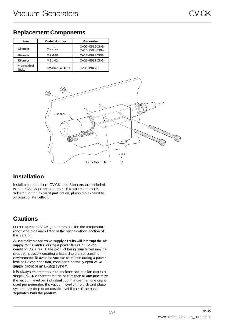
MC2 S 05 H S 62 L 24 B 5 G
Model Number Index
NozzleDiameter05 0,5 mm07 0,7 mm10 1,0 mm
Vacuum DegreeH High Vacuum
0,92 barL Low Vacuum
0,58 bar
Body TypeL Long
Sensor02 MVS-201-PCP (PNP)22 MPS-V2C-PC (PNP)62 MPS-V6C-PC (PNP)64 MPS-V6C-PG (PNP)Z No Sensor
FunctionS Single Unit
Voltage24 24 VDC
Master ValveAir SupplyA Normally
OpenB Normally
Closed
Valve Connector5 500 mm Lead Clip
w/ Lamp & Surge
Pressure PortG 1/8 BSPP
SupplyPressureS 5 bar
Evacuation TimeSeries / Air Supply Air Evacuation Time in sec / liter
Nozzle Diameter Pressure Consumption to reach different Vacuum Levels [%]
[bar] [l/min] 10 20 30 40 50 60 70 80 90
MC2-05HS 5 10 0,64 1,46 2,48 3,81 5,48 7,56 10,50 15,00 —
MC2-05LS 5 10 0,35 0,82 1,42 2,32 4,36 — — — —
MC2-07HS 5 22,5 0,39 0,89 1,50 2,35 3,41 4,80 6,63 9,75 —
MC2-07LS 5 22,5 0,26 0,63 1,13 2,00 3,80 — — — —
MC2-10HS 5 44 0,19 0,43 0,72 1,14 1,84 3,01 4,25 6,51 —

142 04.10
www.parker.com/euro_pneumatic
The “V2” sensor has 2 independent NPN or PNP outputsavailable for vacuum confirmation. Typical response timesfor the outputs with an average circuit is less than 50 msec.The output response time of this sensor is less than 2 msec.
The “V2” sensor is available with an M8, 4-Pin or grommeted(2M) electrical connector. The mating M8, 4-Pin cable is notincluded with the MPS-2 Sensor and must be orderedseparately. See MC2 Accessories for cable options.
The “201” sensor has one output NPN or PNP for vacuumconfirmation and a control output that interfaces directlywith the blow-off release pilot valve. With programmabletime control features and a special chip driver, the sensorautomatically activates the blow-off release when the vacuumsignal from the PLC is discontinued. This eliminates a PLCoutput to activate the blow-off release. This new technologyreduces PLC output requirements by 50% and reducesinstallation to a simple 4 wire system. The output responseof the sensor is less than 2 msec.
The “201” sensor is available with an M8, 4-Pin electricalconnector. The MC2-201 valve cable and the mating M8,4-Pin cable are not included with the MVS-201 Sensor andmust be ordered separately. See MC2 Accessories for cableoptions.
The “V6” sensor has one normally open and one normallyclosed NPN or PNP output available for vacuum confir-mation. The MPS-6 sensor is a cost effective performerwith an output response time less than 1 msec. and a niceadjustable 220 degree output range.
The “V6” sensor is available with an M8, 4-Pin or grommeted(2M) electrical connector. The mating M8, 4-Pin cable is notincluded with the MPS-6 Sensor and must be orderedseparately. See MC2 Accessories for cable options.
Vacuum Generators – Sensor Options MC2
MC2 with MPS-6 Series
MC2 with MPS-2 Series
MC2 with MVS-201 Series

143 04.10
www.parker.com/euro_pneumatic
B
Vacuum Generators – Sensor Options MC2
Basic System
PLC
IN
OUT
-
+
Vacuum PartPresent Output
+-
MPS-6 MainCircuit
Brown
Blue
Black
White
+24VDC (Connect to Power Supply)
- Ground (Connect to Common)
Output 1, N.O. (Connect to PLC Input, Load, or Relay)
Output 2, N.C. (Connect to PLC Input, Load, or Relay)
Output AdjustmentRotate the potentiometer trimmer to increaseor decrease pressure switch point output.Excessive force or exceding the limits of the trimmers may cause damage.
Basic System
PLC
IN
OUT
-
+Vacuum Pilot ValveBlow-Off Pilot Valve
Sensor Output 1Sensor Output 2
Vacuum Pilot ValveBlow-Off Pilot Valve
Vacuum System Programming
Vacuum System Programming
( V )
( B )
MPS-2Main
Circuit
Brown
Blue
Black
White
+24VDC (Connect to Power Supply)
- Ground (Connect to Common)
Output 1, N.O. or N.C. (Connect to PLC Input, Load, or Relay)
Output 2, N.O. or N.C. (Connect to PLC Input, Load, or Relay)
Output AdjustmentSensor functions and outputs areprogrammed by touch panel.
2 1
Vacuum System Programming
( V )
( B )
( V )
MVS-201Main
Circuit
Brown
Blue
Black
White
+24VDC (Connect to Power Supply)
- Ground (Connect to Common)
Output 1, N.O. or N.C. (Connect to PLC Input, Load, or Relay)
+24VDC (Input to Activate Vacuum)
Output AdjustmentSensor functions and outputs areprogrammed by touch panel.
2 1
Basic System with 201 Sensor
PLC
IN
OUT
-
+Sensor
Vacuum Part Present Output
MC2 with MPS-6 Series
MC2 with MPS-2 Series
MC2 with MVS-201 Series

144 04.10
www.parker.com/euro_pneumatic
Vacuum Generators – Manifolds MC2
Station Station Station StationStation Station Station Station1 2 3 4 5 6 7 8
Manifold Part Number
MC2 - M 2 G
Port SizeG 1/8 BSPP
Stations2345678

145 04.10
www.parker.com/euro_pneumatic
B
Vacuum Generators – Manifolds MC2
18
6,520
54
78,5
88
20
8,67,5
29,5
11,5 12,5
Ø 4 (2x)M5x0,8
For V2 & 201 Sensor
For V6 Sensor
G: 1/8 BSPP
4
48,8
11
18 20,5
A
18
21
68,5
13,5
x (n-1)
Ø 4,5 4x
G: 1/8 BSPP
Generator
Manifold3-Station Manifold Shown
3 StationManifoldShown
Pressure PortBlock
Screw
O-ring
Manifold AssemblyRemove Pressure Port Block anduse existing O-ring and Screw tosecure the MC2 unit to the Manifold.
n 2 3 4 5 6 7 8
A 56,5 77 97,5 118 138,5 159 179,5
Millimetern = Number of Stations

146 04.10
www.parker.com/euro_pneumatic
Sensor
Sensor O-ring(P5)
PilotValves
VacuumPort
Sensor MountingScrews (M2.0x16 mm)
Valve MountingScrews (M1.6x12 mm)
5
FilterHousing
Mounting Kit
4
7
7Silencer
Pressure PortBlock
1
FilterElement 3
FilterCap 2
++-
-
CautionsDo not use or expose the MC2 with fluids or corrosivegases. Vacuum Venturi’s are designed to be used with non-lubricated, non-corrosive, compressed air.
Do not operate MC2 generators outside the temperaturerange and pressures listed in the specifications section ofthis catalog. Regulate the compressed air to 4,8 bar andfiltrate with a maximum 40 micron filter. Non-lubricatedcompressed air will maintain the life and vacuum level of thegenerator.
All normally closed vacuum circuits will interrupt the airsupply to the venturi during a power failure orE-Stop condition. As a result, the product being transferredmay be dropped, possibly creating a hazard to thesurrounding environment. To avoid hazardous situationsduring a power loss or E-Stop condition, consider a normallyopen vacuum circuit.
Vacuum Generators MC2
Check the insulation of all lead wires after installation toavoid shorts. Properly secure all lead wires to avoid stressor repeated movement that may fray lead wires.
Some electrical components are diode or zener diodeprotected. When installing solenoids and sensors, check thepolarity of the component before applying power. Apply theappropriate voltage to the solenoids and sensors.Inappropriate voltage, shorts, or surges may damage thecircuitry.
Replacement ComponentsItem Part Number Description
1 MC2-S Silencer
2, 3, 4 MC2-F Filter Kit
3 MC2-E Filter Element5 MC2-24B N.C. Pilot Valve
7 MC2-B Mounting Kit

147 04.10
www.parker.com/euro_pneumatic
B
Vacuum Generators MC2
Accessories
Ø 5
2 m 32
CB-M8-4P-2M
CB-M8-4P-5M
CB-M8-4P-5M-90
Ø 5
Ø 9,7
5 m 32
Ø 9,7
Ø 5
Ø 9,7
5 m 22
10,719
Sensor Cables
MC2-C201G
Valve Cable
(Connects Sensor to Vacuum &Blow-off Release Pilot Valves)

148 04.10
www.parker.com/euro_pneumatic
Features• Vacuum Generating Pilot Valve
• Vacuum Release Pilot Valve Option
• Vacuum Sensor - Filter - SilencerAvailable
• Regulating Blow-off
• Check Valve Option
• Air-Economizing Controls
• Manifold System
• Vacuum Flow Rates from 60 to130 l/min
Vacuum Generators CVK
CVK
CharacteristicsThe CVK Series vacuum generator provides a completesolution for factory automation. The CVK is perfect fornon-porous applications such as material handling,critical applications involving glass, or general transferapplications. The CVK has integrated vacuum pilot andblow-off release pilot valves to minimize responsetimes. The CVK has additional features; regulatingblow-off needle, 130 micron filter, optional check valve,and a sensor platform for vacuum confirmation. TheCVK can be assembled into a maximum 5 stationmanifold. The unit can be ordered normally open ornormally closed.
Blow-off FlowAdjustment Optional
Sensor
Filter
CheckValve
Venturi
Normally ClosedBlow-off Pilot Valve
Normally ClosedVacuum Pilot Valve
Normally ClosedMaster Valve
Normally ClosedMaster Valve
Blow-off FlowAdjustment Optional
Sensor
Filter
Venturi
Normally ClosedBlow-off Pilot Valve
Normally ClosedVacuum Pilot Valve
Normally OpenMaster Valve
Normally ClosedMaster Valve
CheckValve
PFG Cup PFG Cup
Normally Closed Vacuum CircuitThe Vacuum Pilot is Energized to Activate VacuumThe Vacuum Pilot is Energized to Activate VacuumThe Vacuum Pilot is Energized to Activate VacuumThe Vacuum Pilot is Energized to Activate VacuumThe Vacuum Pilot is Energized to Activate Vacuum
Normally Open Vacuum CircuitThe Vacuum Pilot is Energized to Deactivate VacuumThe Vacuum Pilot is Energized to Deactivate VacuumThe Vacuum Pilot is Energized to Deactivate VacuumThe Vacuum Pilot is Energized to Deactivate VacuumThe Vacuum Pilot is Energized to Deactivate Vacuum

149 04.10
www.parker.com/euro_pneumatic
B
Vacuum Generators CVK
CVK 15 H S 62 C 24 B D G
Model Number Index
NozzleDiameter15 1,5 mm20 2,0 mm27 2,7 mm
Vacuum DegreeH High Vacuum
0,92 barL Low Vacuum
0,58 bar
SupplyPressureS 5 bar
Voltage 24 24 VDC
Master ValveAir SupplyA Normally
OpenB Normally
ClosedValve Connector
D DIN w/LED &Surge Protection
Port ThreadsG BSPP
Sensor02 MVS-201-PC (PNP)22 MPS-V2C-PC (PNP)62 MPS-V6C-PC (PNP)64 MPS-V6C-PG (PNP)Z No Sensor
SpecificationsMedia Non-Lubricated Compressed Air, Non-Corrosive Gases
Optimum Operating Pressure 5 barHumidity 35 to 85%
Pressure Port G: 1/4 BSPP FemaleVacuum Port G: 3/8 BSPP Female
Operating Temperature 5 to 50 °CMaterial Aluminium, Brass, NBR
Manifold Weight 2-Station: 680 g, 3-Station: 880 g, 4-Station: 1080 g, 5-Station: 1280 gVacuum Pilot and Blow-off Release Pilot
Type of Control Valve Pilot ValveManual Operation Non-Locking Manual Override
Electrical Connection DIN Connector with LED and Surge ProtectionPower Supply 24 VDC ± 10%
Power Consumption 1,8 WOperating Pressure 5 bar
Pilot Valve Air Supply Normally Closed
PerformanceItem
Nozzle Diameter Vacuum Degree Vacuum Flow Air Consumption Weight[mm] at 5 bar [%] [l/min] [l/min] [g]
15HS 1,5 90 60 100 75015LS 1,5 57 90 100 75020HS 2,0 90 95 180 75020LS 2,0 57 130 180 75027HS 2,7 90 125 295 750
Evacuation TimeSeries / Air Supply Air Evacuation Time in sec / liter
Nozzle Diameter Pressure Consumption to reach different Vacuum Levels [%]
[bar] [l/min] 10 20 30 40 50 60 70 80 90
CVK-15HS 5 100 0,08 0,17 0,28 0,44 0,65 0,93 1,43 2,20 6,70
CVK-15LS 5 100 0,04 0,10 0,19 0,33 0,59 — — — —
CVK-20HS 5 180 0,04 0,09 0,16 0,27 0,43 0,66 1,06 1,89 4,60
CVK-20LS 5 180 0,03 0,08 0,15 0,27 0,55 — — — —
CVK-27HS 5 295 0,02 0,07 0,12 0,20 0,30 0,47 0,70 1,49 —

150 04.10
www.parker.com/euro_pneumatic
Vacuum Generators – Sensor Options CVK
CVK with MPS-6 Series
CVK with MPS-2 Series
CVK with MVS-201 Series
The “V2” sensor has 2 independent NPN or PNP outputsavailable for vacuum confirmation. Typical response timesfor the outputs with an average circuit is less than 50 msec.The output response time of this sensor is less than2 msec.
The “V2” sensor is available with an M8, 4-Pin orgrommeted (2M) electrical connector. The mating M8, 4-Pincable is not included with the MPS-2 Sensor and must beordered separately. See CVK Accessories for cable options.
The “201” sensor has one output NPN or PNP for vacuumconfirmation and a control output that interfaces directly withthe blow-off release pilot valve. With programmable timecontrol features and a special chip driver, the sensorautomatically activates the blow-off release when thevacuum signal from the PLC is discontinued. This eliminatesa PLC output to activate the blow-off release. This newtechnology reduces PLC output requirements by 50% andreduces installation to a simple 4 wire system. The outputresponse of the sensor is less than 2 msec.
The “201” sensor is available with an M8, 4-Pin electricalconnector. The MC2-201 valve cable and the mating M8,4-Pin cable are not included with the MVS-201 Sensor andmust be ordered separately. See CVK Accessories for cableoptions.
The “V6” sensor has one normally open and one normallyclosed NPN or PNP output available for vacuumconfirmation. The MPS-6 sensor is a cost effectiveperformer with an output response time less than1 msec. and a nice adjustable 220 degree output range.
The “V6” sensor is available with an M8, 4-Pin orgrommeted (2M) electrical connector. The mating M8, 4-Pincable is not included with the MPS-6 Sensor and must beordered separately. See CVK Accessories for cable options.

151 04.10
www.parker.com/euro_pneumatic
B
Vacuum Generators – Sensor Options CVK
Basic System
PLC
IN
OUT
-
+
Vacuum PartPresent Output
+-
MPS-6 MainCircuit
Brown
Blue
Black
White
+24 VDC (Connect to Power Supply)
- Ground (Connect to Common)
Output 1, N.O. (Connect to PLC Input, Load, or Relay)
Output 2, N.C. (Connect to PLC Input, Load, or Relay)
Output AdjustmentRotate the potentiometer trimmer to increaseor decrease pressure switch point output.Excessive force or exceding the limits of the trimmers may cause damage.
Basic System Air-Economizing System
PLC
IN
OUT
PLC
IN
OUT
-
+Vacuum Pilot ValveBlow-Off Pilot Valve
Sensor Output 1Sensor Output 2
Vacuum Pilot ValveBlow-Off Pilot Valve
Vacuum System Programming
Vacuum System Programming
( V )
( B )
MPS-2Main
Circuit
Brown
Blue
Black
White
+24 VDC (Connect to Power Supply)
- Ground (Connect to Common)
Output 1, N.O. or N.C. (Connect to PLC Input, Load, or Relay)
Output 2, N.O. or N.C. (Connect to PLC Input, Load, or Relay)
Output AdjustmentSensor functions and outputs areprogrammed by touch panel.
2 1
Vacuum System Programming
( V )
( B )
( V )
MVS-201Main
Circuit
Brown
Blue
Black
White
+24 VDC (Connect to Power Supply)
- Ground (Connect to Common)
Output 1, N.O. or N.C. (Connect to PLC Input, Load, or Relay)
+24VDC (Input to Activate Vacuum)
Output AdjustmentSensor functions and outputs areprogrammed by touch panel.
2 1
Basic System with 201 Sensor
PLC
IN
OUT
-
+Sensor
Vacuum Part Present Output
N.C. Output 1 - Air EconomizingN.O. Output 2 - Part Present Output
PNP
PNP
Out 2Out 1 Sensor
VACSolenoid
Blow-OffSolenoid
+
-
CVK with MPS-6 Series
CVK with MPS-2 Series
CVK with MVS-201 Series

152 04.10
www.parker.com/euro_pneumatic
Vacuum Generators – Manifolds CVK
Station Station Station Station Station1 2 3 4 5
Manifold Block
CVK - M 2 G
Manifold Port SizeG 1/8 BSPP
Stations2345

153 04.10
www.parker.com/euro_pneumatic
B
Pressure InletPort
Exhaust Port
Generator MountingScrews (M4x35)
RemoveSilencerAssembly
Remove PressurePort Block
3 StationManifoldShown
O-ring
Screws
Vacuum Generators – Manifolds CVK
12 M
OD
E
22 61,5
177,4
26Ø 5,52x
45,6
90
50
17,5
6 15
M8
Vacuum Port3/8 BSPP
Pressure Port1/4 BSPP
Generator
18
1830
30
AB23x(n-1)
40
17,5
20
90
15 2550
100
9 7,54x
35
Exhaust Port3/4 BSPP
Pressure Port1/2 BSPP
5,54x
12 12
45,6
E
P
Manifold3-Station Manifold Shown
Manifold AssemblyRemove Pressure Port Block andSilencer Assembly. Use existingO-rings and Manifold MountingScrews to secure the CVK unit tothe Manifold.
n 2 3 4 5
A 83 106 129 152
B 65 88 111 134
Millimetern = Number of Stations

154 04.10
www.parker.com/euro_pneumatic
Vacuum Generators CVK
Sensor
SensorO-Ring(P5)
SensorMountingBrkt.
Sensor MountingBrkt. Screws(M3x6)
Sensor MountingScrews (M2x6)
VacuumPort
PressurePort MountingScrews (M4x35)
FilterBase
PilotValve
DINConnector
9
FilterElement
FilterGasket
5
6
7
3
FilterCap
Filter O-ring(M8x1.0)
4FilterHousing
2 Valve MountingScrews (M3x18)
10
18 Silencer
Pressure PortO-Ring (M14x1.5)
Pressure PortBlock
Gasket
CautionsDo not use or expose the CVK with fluids or corrosivegases. Vacuum Venturi’s are designed to be used with non-lubricated, non-corrosive, compressed air.
Do not operate CVK generators outside the temperaturerange and pressures listed in the specifications section ofthis catalog. Regulate the compressed air to 4,8 bar andfiltrate with a maximum 40 micron filter. Non-lubricatedcompressed air will maintain the life and vacuum level of thegenerator.
All normally closed vacuum circuits will interrupt the airsupply to the venturi during a power failure orE-Stop condition. As a result, the product being transferredmay be dropped, possibly creating a hazard to thesurrounding environment. To avoid hazardous situationsduring a power loss or E-Stop condition, consider a normallyopen vacuum circuit.
Check the insulation of all lead wires after installation toavoid shorts. Properly secure all lead wires to avoid stressor repeated movement that may fray lead wires.
Some electrical components are diode or zener diodeprotected. When installing solenoids and sensors, check thepolarity of the component before applying power. Apply theappropriate voltage to the solenoids and sensors.Inappropriate voltage, shorts, or surges may damage thecircuitry.
Replacement ComponentsItem Part Number Description
1 CVK-S Silencer
2 thru 7 CVK-F Filter Kit
5 CVK-E Filter Element8, 9, 10 CVK-24D Pilot Valve Kit

155 04.10
www.parker.com/euro_pneumatic
B
Vacuum Generators CVK
Accessories
Sensor Cables
Ø 5
2 m 32
CB-M8-4P-2M
CB-M8-4P-5M
CB-M8-4P-5M-90
Ø 5
Ø 9,7
5 m 32
Ø 9,7
Ø 5
Ø 9,7
5 m 22
10,719
CVK-D201G
Valve Cable
(Connects Sensor to Vacuum &Blow-off Release Pilot Valves)

156 04.10
www.parker.com/euro_pneumatic
Vacuum Generators CVX-0260B
CVX-0260B E-Stop Features• Optional DeviceNet™ Communication
• E-Stop Operating System (Patented)
• Eliminates All UnnecessaryAir Consumption
• Fast Sensor and Vacuum FlowResponse Times
• Large Vacuum Flow Rates
• Independent Vacuum Channels
PFG Cup
Sensor
Venturi
N.C. MasterValve
N.C. MasterValve
Filter
FlowControl
VacuumPilotValve
1
E-stop System
5
Blow-offPilotValve
4 CheckValve
3
2
The CVX-0260B is a CVK package with the ultimate aircircuit for all of your material handling systems. TheCVX-0260B is ideal for non-porous applications thatrequire fast response of large vacuum and blow-offrelease flow rates, E-Stop Management System,optional air-economizing features, and device netcommunication. The E-Stop Management System canoperate a normally closed system during an E-Stop orpower failure situation. Typically, with a normallyclosed air circuit, the user controls the vacuum with acommand signal. During an E-stop or power failureevent, the vacuum command signal is lost, but, thesystem can detect the presence of a part and continueto operate in the vacuum mode. If the system detectsthat a part is not present, each vacuum channel,operating independently, will close to eliminate anyunnecessary air consumption. Additional aireconomizing features are controlled by the sensoroutputs to make this unit the ultimate weapon againstair consumption.
There are 4 separate states of air logic: vacuum, blow-off, idle, and EOS. The air circuit to the right illustratesa basic normally closed unit with the E-Stop operatingsystem. Vacuum is created when a high signal is sentto Vacuum Pilot Valve (1). The output of the vacuumSensor (2), controls the vacuum level and aireconomizing function by feedback to the VacuumSolenoid Valve (1). The Check Valve (3) maintains thevacuum level until the Blow-off Pilot Valve (4) isactivated to release or the hysteresis value of Sensor(2) is reached to restore the original vacuum level. TheE-Stop operating system (5) is activated by an E-Stopor power failure.
Characteristics Vacuum Controlled E-Stop CircuitThe Vacuum Pilot is Energized to Activate Vacuum. TheE-Stop Management System can maintain the last state of airduring E-Stop or power failure.

157 04.10
www.parker.com/euro_pneumatic
B
Vacuum Generators CVX-0260B
SpecificationsCVX-0260B Specifications
Media Non-lubricatedCompressed Air, Dry Air
Pressure Port G
Vacuum Ports G Ports
Operating Temperature 0 to 55 °C
Humidity 35 to 85% R.H.
Operating Pressure 5 bar
Vacuum Filtration 130 µm
Noise Level 72 dB
Air Consumption 295 I/min
Vacuum Flow 125 I/min
Sensor Response Time < 2 msec
Maximum Vacuum Level -0,92 bar
Cover 300 Series 22 GaugeStainless Steel
Control Valve Specifications
3-Way Pilot Valves
Manual Operation Manual Overrides Available
Electrical Connector DIN type w/LED and DiodeProtection, IP65 Rating
Power Supply 24 VDC ± 10%
Power Consumption 1,8 W
Pressure Range 1,5 to 10 bar
Pilot Valve Air Supply Normally Closed
Mass 57 g
E-Stop Operating System Specifications
Two-Way Valve Diaphragm Actuated,Pneumatic Output
Media Non-lubricated Air, Dry Air
Switch Point Pressure 0,3 bar
Operating Range -0,15 to -0,85 bar Vacuum
Pressure Through-put Range 1,51 to 8 bar
Accuracy ± 0,05 bar
Port Connection M5 Female
Air Supply Normally Closed
Mass 34 g
Aux. Power Electrical Valve Specifications
3-Way Valve Direct Acting
Media Compressed Air,Non-lubricated
Operating Range 0 to 7,03 bar
Electrical Connection DIN Connector w/LED andDiode Protection, IP65
Operating Voltage 24 VDC ± 10%
Power Consumption 1,8 W
Current 0,075 A
Air Supply Normally Open
Mass 61 g
Check Valve Specifications
One Way One Way Spring Return
Operating Pressure -0,9 to 16 bar
Mass 10 g
Performance
ItemNozzle Diameter Vacuum Degree Vacuum Flow Air Consumption Weight
[mm] at 5 bar [%] [I/min] [I/min] [g]
27HS 2,7 90 125 295 748
CVX-0260B E0S DN G
Model Number Index
Port ThreadsG 3/8 BSPP
CommunicationDN DeviceNet™— Without
E-StopCircuit
Evacuation TimeSeries / Air Supply Air Evacuation Time in sec / liter
Nozzle Diameter Pressure Consumption to reach different Vacuum Levels [%]
[bar] [l/min] 10 20 30 40 50 60 70 80 90
CVX-27HS 5 295 0,02 0,07 0,12 0,20 0,30 0,47 0,70 1,49 —

158 04.10
www.parker.com/euro_pneumatic
Vacuum Generators CVX-0260B
65,0 89,2109,5
44,6
57,050,0
Blow Off Valve
Mounting Holes4 - 25.5 (4 Places)
Blow Off NeedleAdjustment Vacuum Valve Vacuum Filter
Housing
17,0
31,7
300,2
228,5
162,0
Silencer
Pressure Ports2-G3/8
49,4
DevicenetCommunication
DevicenetPower
Vacuum Ports2-G3/8
23,0
33,1
154,8
17,5Vacuum Sensors

159 04.10
www.parker.com/euro_pneumatic
B
Vacuum Generators CVX-0260B
Sensor
SensorO-Ring(P5)
SensorMountingBrkt.
SensorMountingBrkt. Screws(M3x5)
SensorMountingScrews(M2x6)
VacuumPort
GeneratorMountingScrews(M4x35)
FilterBase
PilotValve
AuxiliaryValve
AuxiliaryValve Gasket
DINConnector
9
11FilterElement
FilterGasket
5
6
7
3
FilterCap
Filter O-ring(M8x1.0)
4FilterHousing
2 Valve MountingScrews (M3x18)
Diaphragm Valve
Diaphragm ValveMounting Screw(M3x20)
12
10
18
Auxiliary ValveMounting Screws(M2x25)
Silencer
O-Ring(M14x1.5)
Gasket
CautionsDo not use or expose the CVX with fluids or corrosivegases. Vacuum Venturi’s are designed to be used with non-lubricated, non-corrosive, compressed air.
Do not operate CVX generators outside the temperaturerange and pressures listed in the specifications section ofthis catalog. Regulate the compressed air to 4,8 bar andfiltrate with a maximum 40 micron filter. Non-lubricatedcompressed air will maintain the life and vacuum level of thegenerator.
Check the insulation of all lead wires after installation toavoid shorts. Properly secure all lead wires to avoid stressor repeated movement that may fray lead wires.
Some electrical components are diode or zener diodeprotected. When installing solenoids and sensors, check thepolarity of the component before applying power. Apply theappropriate voltage to the solenoids and sensors.Inappropriate voltage, shorts, or surges may damage thecircuitry.
Replacement ComponentsItem Part Number Description
1 CVK-S Silencer
2 thru 7 CVK-F Filter Kit
5 CVK-E Filter Element8, 9, 10 CVK-24D Pilot Valve Kit

160 04.10
www.parker.com/euro_pneumatic
CVX-0260-B - E-Stop OperatingSystem (EOS)The E-Stop Operating System is designed to maintain the laststate of operation when an E-stop or power failure occurs.
Vacuum Generators CVX-0260B
CVX-0260-B - System Logic
Vacuum ON Commandfrom System Controls
Idle
Vacuum BeginsVacuumMode
Continues
MaximumSetting Reached
Yes
Yes
Yes
No
No
CommandVac “Off” Blow “On”
No
Is Vacuum LevelMaintained?
Air Conservation BeginsOutput 1 Off
Check Valve MaintainsVacuum Level
Sensor DetectsHysteresis Level
Reached
Vacuum LevelRestored To
Maximum Setting
E-StopSystemTo Idle
E-StopSystem
Vacuum Maintained
The chart below illustrates the state of operation in differentmodes.
Modes Vacuum On Vacuum Off Blow-Off EOS
Normal Conditions Air-economizing between Idle Blow-Off On EOS Off0,61-0,54 bar Blow-Off Idle
Vacuum On Blow-OffEmergency-Stop,
Power Failure,Idle EOS On
Loss of DeviceNet™Communications
Vacuum Onor Power
Vacuum On Air-Restore Power economizing Function Idle Idle EOS Off
Resumes
On
Idle
Idleor

161 04.10
www.parker.com/euro_pneumatic
B
Vacuum Generators CVX-0260B
Male (Pins)
3
1.) Drain2.) V+3.) V-4.) CAN-H5.) CAN-L
4
5
2
1Female (Sockets)
32
1
4
5
Voltage Range: 12,5 - 24 VDCCurrent: 150 mA
Auxiliary PowerBus
Auxiliary PowerBus
OUT CH1 VAC +CH1
Vacuum SOL
DeviceNetBus
Electrical Isolation
DeviceNet Bus
DeviceNet
Opto-Isolators
-Auxilary Power Common
OUT CH1 BLOW +CH1
Blow SOL-Auxilary Power Common
OUT CH2 VAC +CH2
Vacuum SOL-Auxilary Power Common
OUT CH2 BLOW +CH2
Blow SOL-Auxilary Power Common
DeviceNet Power + +
CH1SENSOR
-DeviceNet Power -CH1 OUT1CH1 OUT2
OUT1OUT2
+
CH2SENSOR
-
CH2 OUT1CH2 OUT2
OUT1OUT2
DeviceNet™ Bus Connectors
5-Pin Mini-Style
DeviceNet™The DeviceNet™ power bus supplies power for theDeviceNet circuitry and the two sensors. The auxiliary powerbus provides power for the vacuum solenoids and blow-offsolenoids. The following are power requirements for theDeviceNet circuitry.

162 04.10
www.parker.com/euro_pneumatic
CharacteristicsThe CEK is a CVK unit with a Normally Closed E-Stopvalve that maintains the last state of air during anE-stop or power loss. In addition to this, an air-economizing valve has been added to interrupt the airsupply by connecting the output signal from the sensorto minimize air consumption.
This unit is ideal for non-porous applications thatrequire fast response of large vacuum and blow-offrelease flow, an E-Stop valve, optional air-economizingfeatures, and DeviceNet™ communications.
Typically, with a Normally Closed air Circuit, the usercontrols vacuum with a command signal. During anE-Stop or power failure event, the vacuum commandsignal is lost, but, the E-Stop valve (1) remains in thecurrent operating position due to the construction ofthe valve. The air-economizing valve (5), in a NormallyOpen configuration, passes the air supply from theE-Stop valve (1). The Sensor (2) output activates theair-economizing valve (5) closing the air supply to theNormally Closed master valve. The Check Valve (3)maintains the achieved vacuum level until thehysteresis value of the Sensor (2) is reached or whenthe E-Stop valve (1) has been returned to the closedposition to stop the vacuum operation.
Vacuum Generators CEK
CEK E-Stop Features• Integrated Double Solenoid for Last State
• Integrated Vacuum Pilot
• Integrated Blow-off Pilot
• Integrated Filter, Silencer
• Air Economizing Capabilities
• DeviceNet™ Capable
• Manifolds for up to 5 Units
PFG Cup
E-StopValve
AirEconomizing
Valve
CheckValve
Sensor
VenturiN.C. MasterValve
N.C. MasterValve
Blow-offPilotValve
Filter
FlowControl
1 5
4
3
2
Valve Controlled E-Stop Circuit

163 04.10
www.parker.com/euro_pneumatic
B
Vacuum Generators CEK
CEK 15 H S 22 C 24 B L G
Model Number Index
NozzleDiameter15 1,5 mm20 2,0 mm27 2,7 mm
Vacuum DegreeH High Vacuum
0,92 bar
SupplyPressureS 5 bar
Valve 24 24 VDC
Port ThreadsG BSPP
Air SupplyB Normally
Closed
Valve ConnectorL Clip w/LED &
Surge ProtectionVacuum Releaseand Check Valve
Code Release Valve Check ValveC With With
Sensor22 MPSV2CPC (PNP)Z No Sensor
SpecificationsMedia Non-Lubricated Compressed Air, Non-Corrosive Gases
Operating Pressure 5 barHumidity 35 to 85%
Pressure Port G: 1/4 BSPP FemaleVacuum Port G: 3/8 BSPP Female
Operating Temperature 5 to 50 °CMaterial Aluminium, Brass, NBR
Manifold Weight 2-Station: 680 g, 3-Station: 880 g, 4-Station: 1080 g, 5-Station: 1280 g
Air-Economizing Valve and Blow-off Release Pilot E-Stop ValveType of Control Valve Pilot Valve Double Solenoid
Manual Operation Manual Override Manual OverridesElectrical Connection Clip Connector with LED and Surge Clip Connector with LED and Surge
Power Supply 24 VDC ± 10% 24 VDC ± 10%Power Consumption 0,9 W 0,9 W
Operating Pressure 5 bar 5 barAir Supply Normally Closed Normally Closed
Performance
ItemNozzle Diameter Vacuum Degree Vacuum Flow Air Consumption Weight
[mm] at 5 bar [%] [l/min] [l/min] [g]
15HS 1,5 90 60 100 75020HS 2,0 90 95 180 75027HS 2,7 90 125 295 750
Evacuation TimeSeries / Air Supply Air Evacuation Time in sec / liter
Nozzle Diameter Pressure Consumption to reach different Vacuum Levels [%]
[bar] [l/min] 10 20 30 40 50 60 70 80 90
CEK-15HS 5 100 0,08 0,17 0,28 0,44 0,65 0,93 1,43 2,20 6,70
CEK-20HS 5 180 0,04 0,09 0,16 0,27 0,43 0,66 1,06 1,89 4,60
CEK-27HS 5 295 0,02 0,07 0,12 0,20 0,30 0,47 0,70 1,49 —

164 04.10
www.parker.com/euro_pneumatic
Vacuum Generators – Manifolds CEK
Station Station Station Station Station1 2 3 4 5
Manifold Block
CVK - M 2 G
Manifold Port SizeG 1/8 BSPP
Stations2345

165 04.10
www.parker.com/euro_pneumatic
B
Vacuum Generators – Manifolds CEK
Pressure InletPort
Exhaust Port
Generator MountingScrews (M4x35)
RemoveSilencerAssembly
Remove PressurePort Block
3 StationManifoldShown
O-ring
Screws
12 M
OD
E
22 61,5
177,4
26Ø 5,52x
33,1
90
50
17,5
6 15
M8
Vacuum Port3/8 BSPP
Pressure Port1/4 BSPP
Generator
18
1830
30
AB23x(n-1)
40
17,5
20
90
15 2550
100
9 7,54x
35
Exhaust Port3/4 BSPP
Pressure Port1/2 BSPP
5,54x
12 12
E
P
33,1
Manifold3-Station Manifold Shown
Manifold AssemblyRemove Pressure Port Block andSilencer Assembly. Use existingO-rings and Manifold MountingScrews to secure the CEK unit tothe Manifold.
n 2 3 4 5
A 83 106 129 152
B 65 88 111 134
Millimetern = Number of Stations

166 04.10
www.parker.com/euro_pneumatic
Vacuum Generators CEK
CautionsDo not use or expose the CEK with fluids or corrosivegases. Vacuum Venturi’s are designed to be used with non-lubricated, non-corrosive, compressed air.
Do not operate CEK generators outside the temperaturerange and pressures listed in the specifications section ofthis catalog. Regulate the compressed air to 4,8 bar andfiltrate with a maximum 40 micron filter. Non-lubricatedcompressed air will maintain the life and vacuum level of thegenerator.
Check the insulation of all lead wires after installation toavoid shorts. Properly secure all lead wires to avoid stressor repeated movement that may fray lead wires.
Some electrical components are diode or zener diodeprotected. When installing solenoids and sensors, check thepolarity of the component before applying power. Apply theappropriate voltage to the solenoids and sensors.Inappropriate voltage, shorts, or surges may damage thecircuitry.
Sensor
SensorO-Ring(P5)
SensorMountingBrkt.
SensorMountingBrkt. Screws(M3x5)
SensorMountingScrews(M2x6)
VacuumPort
FilterBase
FilterElement
FilterGasket
5
6
7
3
FilterCap
Filter O-ring(M8x1.0)
4FilterHousing
2
Valve MountingScrews (M3x18)
1 Silencer
Blow-offPilotValve
E-StopValve
8Air-EconomizingValve
9
10
Valve MountingScrews (M3x18)
PressurePort Block
O-ring
Screws
Replacement ComponentsItem Part Number Description
1 CVK-S Silencer
2 thru 7 CVK-F Filter Kit
5 CVK-E Filter Element

167 04.10
www.parker.com/euro_pneumatic
B
CEK - E-Stop Operating System(EOS)The E-Stop Operating System is designed to maintain the laststate of operation when an E-stop or power failure occurs.
Vacuum Generators CEK
CEK - System Logic
Vacuum ON Commandfrom System Controls
Idle
Vacuum BeginsVacuumMode
Continues
MaximumSetting Reached
Yes
Yes
Yes
No
No
CommandVac “Off” Blow “On”
No
Is Vacuum LevelMaintained?
Air Conservation BeginsOutput 1 Off
Check Valve MaintainsVacuum Level
Sensor DetectsHysteresis Level
Reached
Vacuum LevelRestored To
Maximum Setting
E-StopSystemTo Idle
E-StopSystem
Vacuum Maintained
The chart below illustrates the state of operation in differentmodes.
Modes Vacuum On Vacuum Off Blow-Off EOS
Normal Conditions Air-economizing between Idle Blow-Off On EOS Off0,61-0,54 bar Blow-Off Idle
Vacuum On Blow-OffEmergency-Stop,
Power Failure,Idle EOS On
Loss of DeviceNet™Communications
Vacuum Onor Power
Vacuum On Air-Restore Power economizing Function Idle Idle EOS Off
Resumes
On
Idle
Idleor
168 04.10
www.parker.com/euro_pneumatic
Vacuum Generators P5V-GA
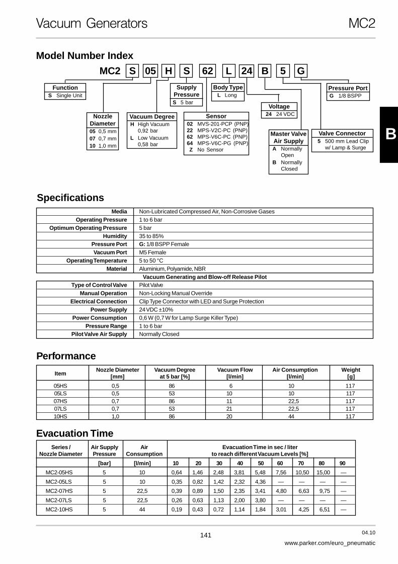
This range of generators give high vacuum at low supply pres-sure, which makes them economical on energy. The genera-tors provide more than 85% vacuum at 4 bar supply pressure,and are made from anodised aluminium with no moving parts,which gives them high reliability.
Typical applications are suction cups, evacuation of moulds,metering of fluids and powders, vacuum chucks, leakage find-ing, evacuation of contaminated media etc.
The generators are provided with a special union for quickand controlled component blow-off. This union can also beused to add optional equipment such as a vacuum monitor,vacuum gauge etc.
Model Number Index
Possible combinations and ordercodes, see main data sheet.
Specification
MaterialBody AluminiumNozzle Brass
Options and additional information
Nozzle in acetal plastic on request.
20 40 60 80
20
40
60
00
Nl/min
%
600
20 40 60 80
100
200
300
400
500
00
Nl/min
%
Suction flow as function of vacuum level
Size 12
Size 03
Size 06
Size 24
Size 42
Size 72
Port size vacuumOptions and accessories
R* With rapid release connection
V* Fitted with holding valve withrapid release connection
N No rapid release, only Size 72
* These features are not availableon size 72
Size
03 30 Nl/min
06 60 Nl/min
12 120 Nl/min
24 240 Nl/min
42 420 Nl/min
72 720 Nl/min
P5V - GA R 0 3 1 2

169 04.10
www.parker.com/euro_pneumatic
B
Time to evacuate Air consumption Port size Weight Order code1litre to 75% vacuum1litre to 75% vacuum1litre to 75% vacuum1litre to 75% vacuum1litre to 75% vacuum at 4 barat 4 barat 4 barat 4 barat 4 bar (vacuum)
[s] [Nl/min] [kg]
Basic6,00 30 Female G1/4 0,08 P5V-GAR03123,00 60 Female G1/2 0,11 P5V-GAR06141,50 120 Female G1/2 0,14 P5V-GAR12140,75 240 Female G1/2 0,19 P5V-GAR24140,45 420 Female G3/4 0,24 P5V-GAR42160,25 720 Female G1/2 0,55 P5V-GAR7214
With holding valve3,00 60 Female G1/2 0,32 P5V-GAV06141,50 120 Female G1/2 0,34 P5V-GAV12140,75 240 Female G1/2 0,40 P5V-GAV24140,45 420 Female G3/4 0,45 P5V-GAV4216
Air supply pressure for optimum vacuum level (92%): 4 bar
Main data for Vacuum Holding Valve, to be fitted to Compact SolidGenerators from P5V-GAR0614 to P5V-GAR4216
Weight Order codekg
0,110,110,110,110,11 8204950201
Vacuum Generators P5V-GA
Generators in sizes 06-42 can also be combined with avacuum lock, VSA60, which is a valve manifold containing twoindependent valves, a vacuum latching valve and an air entryvalve which is installed directly on the generator. The lowspring force means that the vacuum drop across the latchingvalve is minimal. When air supply to the generator ceases, theVSA60 retains the load with vacuum maintained. This givesenergy savings and offers increased safety at the same time.The workpiece can be released quickly with a controlled com-pressed air signal via the air entry port of the vacuum lock.
The VSA60 can also be used separately, complete with flangeunions and a housing to cover it, when you want to install gen-erators centrally, in order to supply several suction cups withvacuum at the same time.
Main data for generator, Compact - Solid
170 04.10
www.parker.com/euro_pneumatic
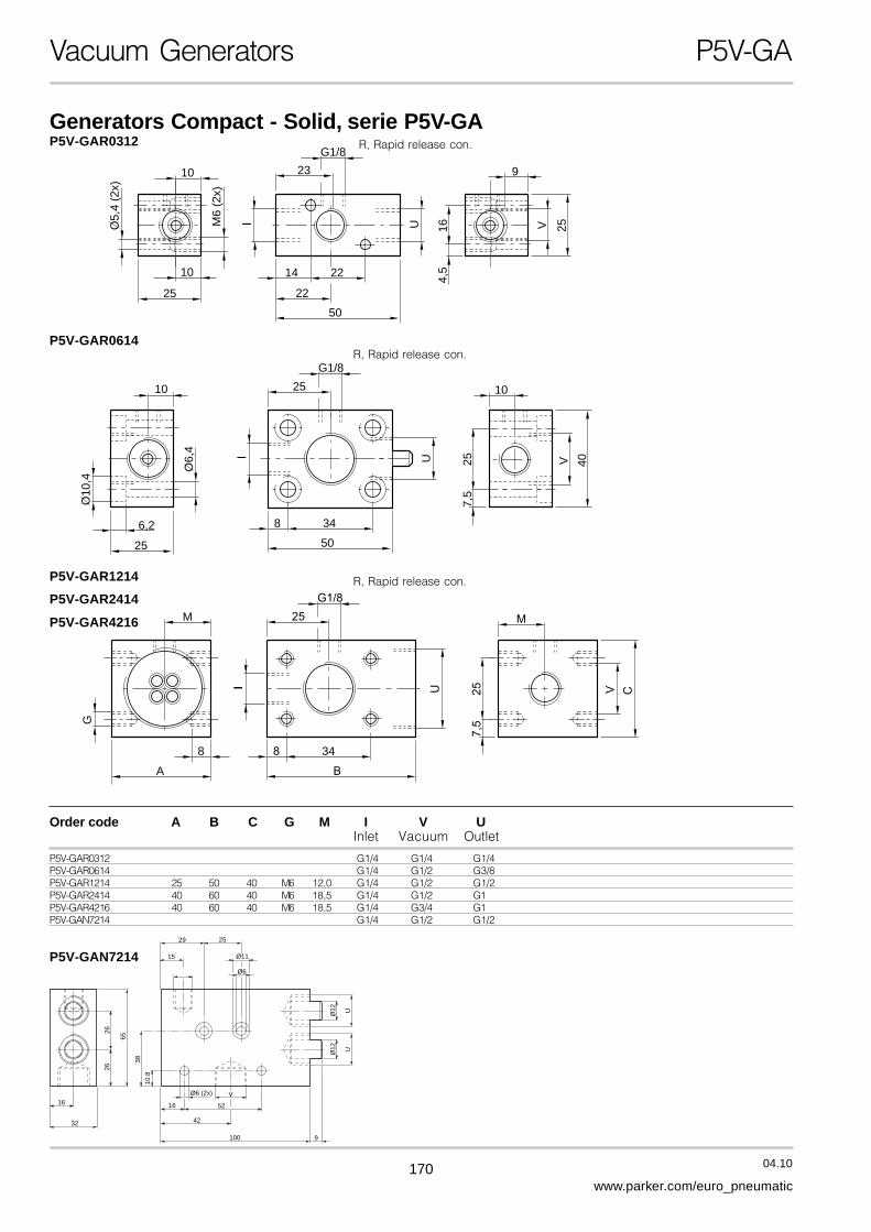
Generators Compact - Solid, serie P5V-GA
16
32
2626
65
2529
Ø11
Ø6
Ø12 U
Ø12 U
9
V
52
Ø6 (2x)
42
16
100
10.8
38
15P5V-GAN7214
R, Rapid release con.
R, Rapid release con.
R, Rapid release con.P5V-GAR1214
P5V-GAR2414
P5V-GAR4216
P5V-GAR0614
Vacuum Generators P5V-GA
10
10
O5,
4 (2
x)
22
22
50
14
23
UM6
(2x)
I
G1/8
164,
5
9
25V
25
25
25
6,2
O10
,4
O6,
4
10
40V
7,5
1025
G1/8
I U
50
348
A
348
G
M
Order code A B C G M I V UInlet Vacuum Outlet
P5V-GAR0312 G1/4 G1/4 G1/4P5V-GAR0614 G1/4 G1/2 G3/8P5V-GAR1214 25 50 40 M6 12,0 G1/4 G1/2 G1/2P5V-GAR2414 40 60 40 M6 18,5 G1/4 G1/2 G1P5V-GAR4216 40 60 40 M6 18,5 G1/4 G3/4 G1P5V-GAN7214 G1/4 G1/2 G1/2
P5V-GAR0312

171 04.10
www.parker.com/euro_pneumatic
B
Vacuum Generators P5V-GA
Holding valve
G1/8
4
38
G1/
8
34 50
25
25
40
9 6,2
27
37
Ø 1
8
8,2 G1/
2
Ø 1
0Ø 6
,4

172 04.10
www.parker.com/euro_pneumatic
A range of generators, incorporating integral holding and rapid releasevalve features. The generators are available in four sizes, with airconsumptions ranging from 20 l/min to 60 l/min at a supply pressure of4 bar.
Incorporation of a holding valve allows vacuum to be maintained for atime after loss of the compressed air supply. The length of this time de-pends on the amount of leakage in the system. The holding functionalso allows compressed air to be saved, by operating the generator in-termittently and monitoring the pressure with a vacuum switch.
The rapid release valve is used to break the vacuum by means of com-pressed air, in order quickly to release the load. Operation of this valvehas been improved, so that it now opens at a pressure of only 0.5 bar,which means that a low pressure can be used for releasing the load.
Vacuum Generators P5V-GWV
Size 02
Size 03
Size 04
Size 06
Specification
MaterialBody AluminiumNozzle BrassSeals Nitrile, NBR
20 40 60 80
25
50
75
100
00
Nl/min
%
Suction flow as function of vacuum level
Model Number Index
Size
02 20 Nl/min
03 30 Nl/min
04 40 Nl/min
06 60 Nl/min
P5V - GW V 0 2 1 4
Time to evacuate Air consumption Port size Weight Order code1litre to 75% vacuum at 4 bar (vacuum)
[s] [Nl/min] [kg]
9,0 20 G1/2 Female 0,18 P5V-GWV02146,0 30 G1/2 Female 0,18 P5V-GWV03144,5 40 G1/2 Female 0,18 P5V-GWV04143,0 60 G1/2 Female 0,18 P5V-GWV0614
Air supply pressure for optimum vacuum level (90%): 4 bar
Main data for Generator Compact - AirSaver

173 04.10
www.parker.com/euro_pneumatic
B
O10,5
12,5
25
3010
12,5
15
205
15
40
358,5
A C
50
B
25
60
39,5
11
D
5 3
Vacuum Generators P5V-GWV
Order code A B C D*Inlet Vacuum Outlet Vacuum
P5V-GWV0214 G1/4 G1/2 G1/4 G1/8P5V-GWV0314 G1/4 G1/2 G1/4 G1/8P5V-GWV0414 G1/4 G1/2 G1/4 G1/8P5V-GWV0614 G1/4 G1/2 G1/4 G1/8* Connection for vacuum gauge etc
M5, R, Rapid release con.
Generators Compact - AirSaver, serie GW


FLUIDTECHNIK BOHEMIA, s. r. o., Olomoucká 87, 627 00 BRNO, tel.: +420 548 213 233-5, +420 548 426 811, fax: +420 548 213 238POLIÈKA – Družstevní 422, 572 01, tel.: 461 722 319, fax: 461 721 044 • NOVÉ MÌSTO NAD METUJÍ – Vrchoviny 29, 549 01,
tel./fax: 491 472 844, tel.: 491 472 328 • OPAVA – Hradecká 668/1, 746 01, tel.: 553 770 911, fax: 553 770 912LOUNY – Vladimírská 2457, 440 01, tel./fax: 415 658 703 • PLZEÒ – Brojova 16, 326 00, tel.: 378 121 340, fax: 378 121 341
E-mail: [email protected] • www.fluidtechnik.eu NON STOP linka technické podpory: 548 426 832
• www.parker-origa.cz
Catalogue PDE2507TCUK-a Section B