Pneumatic IS machines offering total configuration ...
8
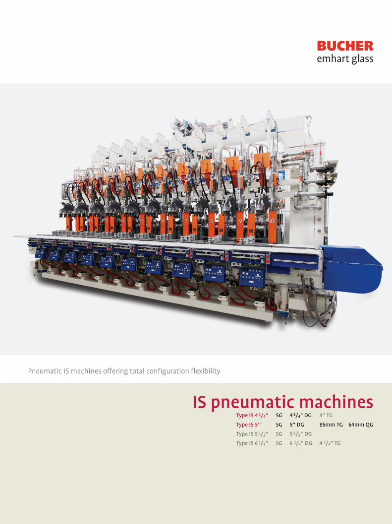
Pneumatic IS machines offering total configuration flexibility IS pneumatic machines Type IS 4 1 / 4 ” SG 4 1 / 4 ” DG 3” TG Type IS 5” SG 5” DG 85mm TG 64mm QG Type IS 5 1 / 2 ” SG 5 1 / 2 ” DG Type IS 6 1 / 4 ” SG 6 1 / 4 ” DG 4 1 / 4 ” TG
Transcript of Pneumatic IS machines offering total configuration ...
Pneumatic IS machines offering total configuration flexibility
IS pneumatic machines Type IS 4 1/4” SG 4 1/4” DG 3” TG
Type IS 5” SG 5” DG 85mm TG 64mm QG
Type IS 5 1/2” SG 5 1/2” DG
Type IS 6 1/4” SG 6 1/4” DG 4 1/4” TG

IS machine specification
Servo feeder• 570 Servo feeder plunger• 555 Revolving tube with servo height and tube drive control• 565 Parallel servo shear
Delivery system• Servo gob distributor, interceptor and center reject position• Constant cone delivery system• Trough and deflector suspension system• Scoops, troughs, and deflectors• Scoop spray system• Valve block on beam for retract cylinder, air ride and scoop
spray
Machine• Machine structure with bed, upright, beam, manifolds and
piping, blank side platform with manifolds and piping • Manifolds and piping for process air in non-corrosive material• Plunger up with FlexPressure System FPS and quick exhaust,
one valve per cavity• Plunger cooling and counterblow with pressure regulator on
the main inlet of the manifold with ISO 3 valve per cavity. Individual cavity adjustment with FlexIS timing system
• Air manifolds on upright and blank side platform• Manifold for process and forming air of rust-proof material
Section frame • 26 line electro-pneumatic valve block with safety flaps for
blow mold open/close and blowhead• Safety interlock switches for blowhead and mold open/close
located on the blow side for easy access• Blank mold holder supporting mechanism• Blank side cooling LH, RH with stack • Pantograph baffle mechanism, two-way air operated• Funnel mechanism, two-way air operated• Invert mechanism, pneumatic with cushioner cartridges• Neck ring mechanism• Blow mold holder supporting mechanism• Constant Cushion take out mechanism • Constant Cushion blowhead top mounted• Blow side cooling with stack • Blow side bottom plate mechanism with VertiFlow thru bed
cooling and blow side vacuum• One set of accessories for blow & blow or press & blow includ-
ing Quick Change accessories for funnel, baffle and blowhead
Feeder options• Feeder front plate• Feeder casing• Feeder refractories• Feeder tube hoist• Shear mechanism lube pump• Shear spray system
Machine structure options• Blank side vacuum including related valves• FPS valves for final blow• Mold and plunger lifting device integrated in overhead
panel• Auxiliary equipment
Section frame options• Blank side cooling with VertiFlow• FPS for counterblow and plunger cooling, one valve per
cavity• Servo Electric Take Out SETO• Servo Electric Invert SEI• Blow side vacuum including related manifolds and valves• NNPB process and accessories• VertiFlow cooling system• Plunger positioner• Blank side InVertiFlow• Vacuum blow side

Bucher Emhart Glass
Control options• Control for proportional valves• Servo Electric Invert SEI and Servo Electric Take Out SETO
Ware handling options• Ware Reject• Ware Transfer 478 / 178• Cross Conveyor• FlexStacker
Service equipment options• FlexLube lubrication system• Flexhoses for air supply• High pressure and low pressure regulators• Filters and condensation drain• Utility equipment, lube pump, Constant Cushion pump
Process control options• Temperature Control System TCS• Plunger Process Control PPC• Closed loop TCS• Closed loop Flex Pressure System FPS plunger• Multi Gob Weight
Fixtures and tools
Control• FlexIS TS-E expandable control system with cables –
incorporates all configuration and setups
Ware handling• FlexConveyor with FlexPusher with a silent chain transport belt
with matched link belt for precise container spacing, height adjustable
• Integrated conveyor ladder to facilitate blow side maintenance• Conveyor valve block with integrated blow mold and blowhead
mechanism interlock• Deadplate cooling high/low with dual infeed valves and height
adjustable
Service• Supervision and installation possibilities
Type 4 1/4” machineMachine for small ware
SG 4 1/4” DG
Type 5” machineFlagship of IS family
SG 5” DG 85mm TG 64mm QG
Type 5 1/2” machineSolid workhorse machine
SG 5 1/2” DG
Type 6 1/4” machineAvailable (outperformed by AIS machine)
SG 6 1/4” DG 4 1/4” TG
“

Ware range Type IS 4 1/4” Type IS 5” Type IS 5 1/2” Type IS 6 1/4”
SG DG 4 1/4” TG 3” SG DG 5” TG 85 QG 64 SG DG 5 1/2” DG 6 1/4” TG 4 1/4”
Blow and blow
Max. height under finish 341 (358) a) 301 276 341 325 244 N.A. 380 (352) b) 343 342 287
Min. height under finish 61 58 59 74 73 55 37 121 68 115 105
Max. body diameter
* with stack cooling 178 90 52 178 102 62 40 178 111 130 90
* with VertiFlow cooling 156 76 51 156 95 60 N.A. 156 102 121 76
Max. finish diameter 48 48 30 48 48 30 N.A. 48 48 48 48
Press and blow
Max. height under finish 265 (282) a) 282 268 265 290 212 N.A. 326 (298) b) 302 301 268
Min. height under finish 74 40 47 74 55 50 18 121 58 105 86
Max. body diameter
* with stack cooling 178 90 52 178 102 62 40 178 111 130 90
* with VertiFlow cooling 156 76 51 156 95 60 N.A. 156 102 121 76
Max. finish diameter 120 83 c) 38 120 90 55 N.A. 120 90 90 70
Narrow neck press and blow
Max. height under finish N.A. 282 268 N.A. 285 212 N.A. N.A. 296 296 268
Min. height under finish N.A. 40 47 N.A. 55 50 N.A. N.A. 57 105 86
Max. body diameter
* with stack cooling N.A. 90 52 N.A. 102 62 N.A. N.A. 111 130 90
* with VertiFlow cooling N.A. 76 51 N.A. 95 60 N.A. N.A. 102 121 76
Max. finish diameter N.A. 38 38 N.A. 38 38 N.A. N.A. 38 38 38
The specified ware ranges are valid when using standard mold equipment, Q.C. plunger mechanisms, through bed/through frame VertiFlow bottom plate mechanisms and blank mold stack cooling (excluding AIS and NIS which have standard InVertiFlow blank side cooling)a) with blow mold stack cooling using non VertiFlow adaptor b) with blow mold stack cooling, with or without non VertiFlow adaptor c) 70mm max. finish with VertiFlow blow mold cooling
* IS 4 1/4” - TG 3” is mostly superceded by IS 5” TG 85mm ** IS 5 1/2” and IS 6 1/4” are mostly superceded in the market by the AIS machine
IS machine ware range
Height under finish- minimum and maximumBody diameter
* **

Bucher Emhart Glass
Plunger up
FlexPressure System FPS standard setting on FlexIS job file
Counter blow/plunger cooling
Manually regulated manifold standard with ISO 3 valve/capacity Optional vacuum blank side with FPS only
Counter blow/plunger cooling option
FPS 1 valve per cavity – FlexIS controlled - job file (outdated pilot regulators on uprights are obsolete)
Any other setup will be handled as a special request.
26 line valve block with override flapsBlow mold and blowhead interlock on FlexConveyor Section frame with interlock
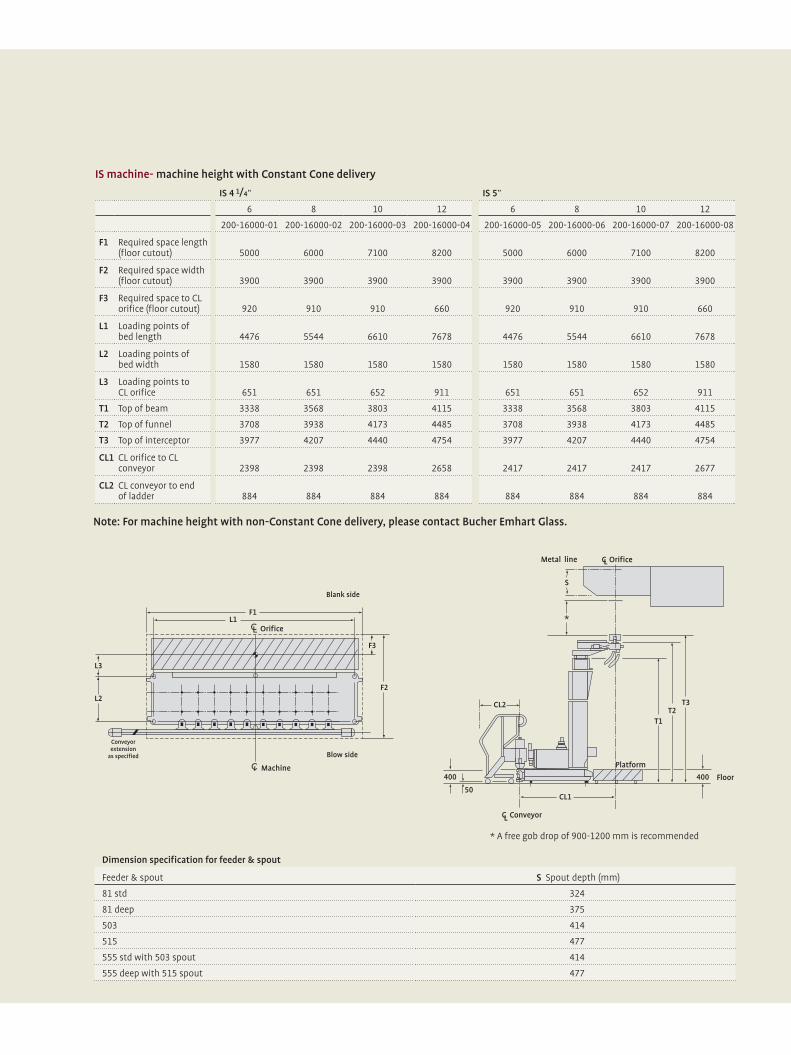
IS machine- machine height with Constant Cone delivery
Dimension specification for feeder & spout
Feeder & spout S Spout depth (mm)
81 std 324
81 deep 375
503 414
515 477
555 std with 503 spout 414
555 deep with 515 spout 477
IS 4 1/4”
6 8 10 12
200-16000-01 200-16000-02 200-16000-03 200-16000-04
5000 6000 7100 8200
3900 3900 3900 3900
920 910 910 660
4476 5544 6610 7678
1580 1580 1580 1580
651 651 652 911
3338 3568 3803 4115
3708 3938 4173 4485
3977 4207 4440 4754
2398 2398 2398 2658
884 884 884 884
IS 5”
6 8 10 12
200-16000-05 200-16000-06 200-16000-07 200-16000-08
5000 6000 7100 8200
3900 3900 3900 3900
920 910 910 660
4476 5544 6610 7678
1580 1580 1580 1580
651 651 652 911
3338 3568 3803 4115
3708 3938 4173 4485
3977 4207 4440 4754
2417 2417 2417 2677
884 884 884 884
F1 Required space length(floor cutout)
F2 Required space width(floor cutout)
F3 Required space to CLorifice (floor cutout)
L1 Loading points of bed length
L2 Loading points of bed width
L3 Loading points to CL orifice
T1 Top of beam
T2 Top of funnel
T3 Top of interceptor
CL1 CL orifice to CLconveyor
CL2 CL conveyor to end of ladder
* A free gob drop of 900-1200 mm is recommended
Note: For machine height with non-Constant Cone delivery, please contact Bucher Emhart Glass.

Bucher Emhart Glass
F1 Required space length(floor cutout)
F2 Required space width(floor cutout)
F3 Required space to CLorifice (floor cutout)
L1 Loading points of bed length
L2 Loading points of bed width
L3 Loading points to CL orifice
T1 Top of beam
T2 Top of funnel
T3 Top of interceptor
CL1 CL orifice to CLconveyor
CL2 CL conveyor to end of ladder
Utility requirements (ref no. 200-1760)
Media Pressure bar
Consumption per section
SG/DG NM3/min
Consumption per section
TG NM3/min
Low pressure operating air 2.1 1.0 1.0
High pressure operating air 3.1 1.0 1.0
Forming air (B&B) 3.1 1.8 1.8
Forming air (P&B) 3.1 2.6 2.6
Vacuum 85% 0.2-0.3 0.2-0.3
Cooling air stack only 1200 mm H20 75.0 60.0
VertiFlow blow side and blank stack 1200 mm H20 50.0 40.0
VertiFlow blank and blow side 1200 mm H20 35.0 N/A
VertiFlow blow side 1200 mm H20 20.0 9.0
Conveyor 600 mm H20 10.0 10.0
Lubrication oil 80.0 1.3 liter/day 1.3 liter/day
Cooling water 2.1 15 liter/min 15 liter/min
• Cooling values show highest possible consumption• Calculate highest-lowest expected heat load = tonnage, cooling system pressures, production, machine type, molds, etc.• Calculated values allow energy efficient fan selection
(A) IS 6 1/4”
6 8 10 12
200-16000-13 200-16000-14 200-16000-15 200-16000-16
5000 6000 7100 8200
4100 4100 4100 4100
920 921 923 660
4476 5544 6610 7678
1580 1580 1580 1580
640 640 639 899
3411 3642 3876 4188
3781 4012 4246 4558
4050 4281 4513 4827
2604 2604 2604 2684
884 884 884 884
IS 5 1/2”
6 8 10 12
200-16000-09 200-16000-10 200-16000-11 200-16000-12
5000 6000 7100 8200
4100 4100 4100 4100
950 940 930 660
4476 5544 6610 7678
1580 1580 1580 1580
620 620 620 878
3411 3642 3876 4188
3781 4012 4246 4558
4050 4281 4513 4827
2566 2566 2526 2826
884 884 884 884
Note: For machine height with non-Constant Cone delivery, please contact Bucher Emhart Glass.
Bucher Emhart Glass makes every effort to provide valid, helpful information to our customers so that our equipment will be best utilized. If you encounter information that is not correct or information which can be misunderstood or not understood, please advise Bucher Emhart Glass so that we can improve this information. All the above figures are typical values and subject to change. For specific project requirements, please contact Bucher Emhart Glass Technical Service.

Emhart Glass Worldwide PresencePrincipalEmhart Glass SAHinterbergstrasse 22CH-6330 Cham, SwitzerlandTel. +41 41 749 42 00 Fax +41 41 749 42 71
Neuss GermanyTel. +49 2131 3595 0 Fax +49 2131 3595 125
Savona ItalyTel. +39 019 51 66 1 Fax +39 019 51 66 301
Kawasaki JapanTel. +81 44 222 7371 Fax +81 44 222 4868
Johor Bahru MalaysiaTel. +6 07 863 1122 Fax +6 07 863 7717
SingaporeTel. +65 6778 1466 Fax +65 6778 9433
Örebro SwedenTel. +46 19 307 500 Fax +46 19 307 501
Sundsvall SwedenTel. +46 60 199 100 Fax +46 60 199 261
St. Petersburg FL USATel. +1 727 471 1113 Fax +1 727 471 1290
Elmira NY USATel. +1 607 734 3671 Fax +1 607 734 1245
Windsor CT USATel. +1 860 298 7340 Fax +1 860 298 7395
Owensville MO USATel. +1 573 437 2132 Fax +1 573 437 3146
Perrysburg OH USATel. +1 567 336 7733 Fax +1 567 336 8727
BR0058RevA