Pneumatic Gripper things MOVE We makePNEUMATIC GRIPPER SSTEM (BPGS) Bimba’s Pneumatic Gripper...
88
We make things MOVE ® Pneumatic Gripper System (BPGS) Best-in-class performance, built to last
Transcript of Pneumatic Gripper things MOVE We makePNEUMATIC GRIPPER SSTEM (BPGS) Bimba’s Pneumatic Gripper...

We makethings MOVE®Pneumatic Gripper
System (BPGS)Best-in-class performance, built to last

BIMBA BIM-BPGS-0319 Catalog 2019 | For Technical Assistance: 800-442-4622
2
Contents
02 Introduction
03 Pneumatic Gripper System (BPGS)
04 Product Features
05 How It Works
06 How It Used
07 How to Specify
08 Regular Jaw Grippers
14 Chisel Jaw Grippers
20 Flange Jaw Grippers
26 Shovel Jaw Grippers
32 Angular Jaw Grippers
38 Hot Metal Regular Jaw Grippers
We Make Things Move®
A forward-thinking innovator, Bimba provides industry-leading pneumatic, hydraulic, electric and vacuum motion solutions that are easy-to-use, reliable and ready for your engineering challenges.
Doing whatever it takes to help you get the job done is what the Bimba companies do best. With an extensive line of industry-leading air cylinders, rotary actuators, linear thrusters, rodless cylinders, NFPA, hydraulics, flow controls, position-sensing cylinders, valves, switches and air preparation equipment, the people of Bimba are ready to tackle your toughest applications.
Bimba is part of IMI Precision Engineering, a world leader in motion and fluid control technologies. Wherever precision, speed and engineering reliability are essential, we deliver exceptional solutions which improve the productivity and efficiency of customers’ equipment.
Our range of high-performance products, such as actuators, valves, valve islands, pressure monitoring controls and air preparation products together with trusted products brands including IMI Norgren, IMI Buschjost, IMI FAS, IMI Herion and IMI Maxseal underpin our position as a leading global supplier.
Part of IMI plc, we have a sales and service network in 75 countries, as well as manufacturing capability in the USA, Germany, China, UK, Switzerland.
44 Hot Metal Flange Jaw Grippers
49 Accessories
62 Reconfigurable Kits
71 Sensors

BIMBA BIM-BPGS-0319 Catalog 2019 | For Technical Assistance: 800-442-4622
3
BIMBA BIM-BPGS-0319 Catalog 2019 | For Technical Assistance: 800-442-4622
Bimba’s Pneumatic Gripper System (BPGS) provides a versatile yet rugged gripping solution for a wide range of applications. This gripper series complements the current line of angular and parallel grippers offering a high gripping force solution for various industries due to the many jaw options offered. Bimba offers angular, regular, chisel, flange, and shovel jaw types. This gripper series features a high gripping force that allows for picking up large heavy objects in the most demanding environments. The long-lasting hardened steel chassis ensures that the gripper can withstand hard impacts with the work piece and other items within the environment.
Pneumatic Gripper System (BPGS)

BIMBA BIM-BPGS-0319 Catalog 2019 | For Technical Assistance: 800-442-4622
4
Product Features
4PN
EUMATIC GRIPPER SYSTEM
(BPGS)
Features and Benefits
• High gripping forces allow for picking up large heavy objects in demanding environments » Up to 450 lbs. at 80 PSI
• Fast actuation time: » 0.05 second close » 0.09 second open » 425 cycles per minute
• Easily repairable by using a single wrench reducing downtime• Long-lasting hardened steel chassis ensures that the gripper
can withstand hard impacts to the work piece and other items within
• Consult factory for custom options » Part presence » Double blank
• Compact in size » 5.34” x 1.65” x 1.04”
Jaw locks closed
Compact in size
Jaw - wide range of options available
In-pad sensors constructed with a
steel face
Hardened Steel Chassis
BIMBA BIM-BPGS-0319 Catalog 2019 | For Technical Assistance: 800-442-4622
5
How It Works5
PNEUM
ATIC GRIPPER SYSTEM (BPGS)
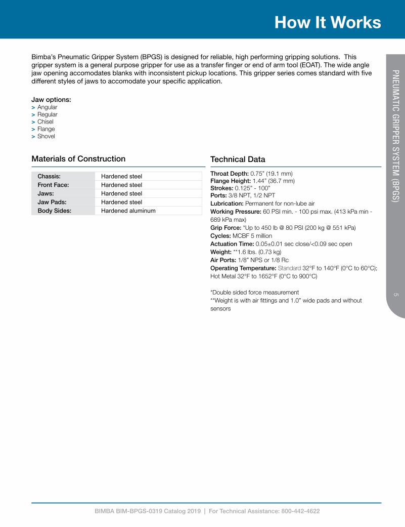
Bimba’s Pneumatic Gripper System (BPGS) is designed for reliable, high performing gripping solutions. This gripper system is a general purpose gripper for use as a transfer finger or end of arm tool (EOAT). The wide angle jaw opening accomodates blanks with inconsistent pickup locations. This gripper series comes standard with five different styles of jaws to accomodate your specific application.
Jaw options: > Angular > Regular > Chisel > Flange > Shovel
Chassis: Hardened steelFront Face: Hardened steelJaws: Hardened steelJaw Pads: Hardened steelBody Sides: Hardened aluminum
Materials of Construction
Throat Depth: 0.75” (19.1 mm)Flange Height: 1.44” (36.7 mm)Strokes: 0.125” - 100”Ports: 3/8 NPT, 1/2 NPTLubrication: Permanent for non-lube airWorking Pressure: 60 PSI min. - 100 psi max. (413 kPa min - 689 kPa max)Grip Force: *Up to 450 lb @ 80 PSI (200 kg @ 551 kPa)Cycles: MCBF 5 millionActuation Time: 0.05±0.01 sec close/<0.09 sec openWeight: **1.6 lbs. (0.73 kg)Air Ports: 1/8” NPS or 1/8 RcOperating Temperature: Standard 32°F to 140°F (0°C to 60°C); Hot Metal 32°F to 1652°F (0°C to 900°C)
*Double sided force measurement**Weight is with air fittings and 1.0” wide pads and without sensors
Technical Data

BIMBA BIM-BPGS-0319 Catalog 2019 | For Technical Assistance: 800-442-4622
6
How It’s Used
6PN
EUMATIC GRIPPER SYSTEM
(BPGS)
• Sheet metal handling• Automated welding• Recreational vehicle• Heavy truck• White goods (appliances)• Construction equipment
• Metal plating and coating• Rail cars• Military vehicle manufacturing• Thermoforming• Plating
Application Ideas
The Pneumatic Gripper System (BPGS) has an expanded list of target applications due to many applications requiring a versatile gripping solution. Since Bimba offers a wide range of jaw options, this gripper series is well suited for industries looking for high gripping force. Within the target industries, there are a variety of applications for the gripper system:
• Pick & place cut sheets• Material transfer of sheet metal within a press• Material clamping during welding operations• Part transfer in plating application• Lifting of heavy bags
Feature Advantage Benefit
Repairable Lower cost of ownership Every part of the gripper can be replaced in only a few minutes reducing downtime and eliminating the need to buy another gripper
Single wrench repair Reduced downtime 4mm hex wrench is all that is needed to repair and reconfigure the gripper making changes fast and easy
Hardened steel chassis Durability Enables the gripper to survive in harsh environments without breaking
Interchangeable pads Flexibility Allows you to match the gripper to the material being held
Adjustable jaw angle Fast cycle times By adjusting the gripper to the proper opening for an applications cycle time can increase by minimizing jaw travel
Double blank sensor Die protection Ensure only one sheet is loaded into the press die preventing costly damage to the press and die
Advantages
Target Applications
BIMBA BIM-BPGS-0319 Catalog 2019 | For Technical Assistance: 800-442-4622
7
How To Specify7
PNEUM
ATIC GRIPPER SYSTEM (BPGS)
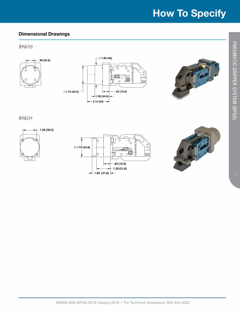
Dimensional Drawings
1.25 (31.8).63 (15.9)
1.65 (41.8)
1.73 (43.8)
1.20 (30.5)
BPGS11
.63 (15.9)1.38 (34.9)
2.13 (54)
1.75 (44.5)
1.89 (48).90 (22.9)
BPGS10

BIMBA BIM-BPGS-0319 Catalog 2019 | For Technical Assistance: 800-442-4622
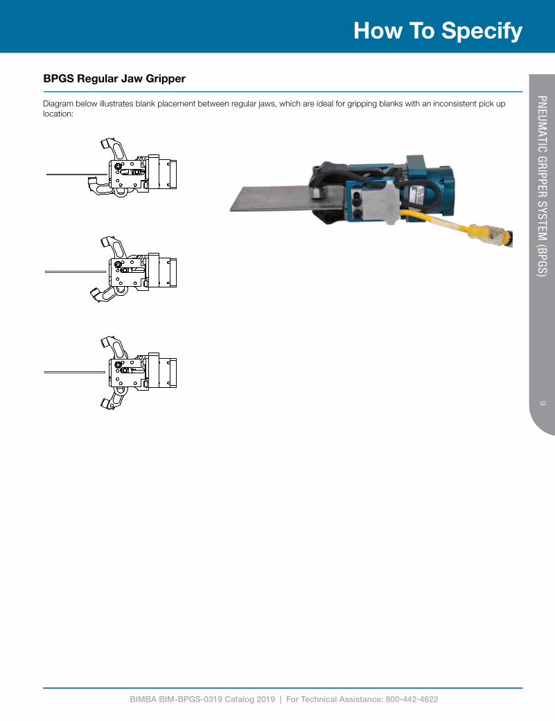
Regular Jaw Grippers
Bimba's regular jaw gripper is a general purpose gripper that is used for transfer finger or end-of-arm tool (EOAT). The wide angle jaw accomodates blanks with inconsistent pick up locations.
BIMBA BIM-BPGS-0319 Catalog 2019 | For Technical Assistance: 800-442-4622
9
How To Specify9
PNEUM
ATIC GRIPPER SYSTEM (BPGS)
BPGS Regular Jaw Gripper
Diagram below illustrates blank placement between regular jaws, which are ideal for gripping blanks with an inconsistent pick up location:

BIMBA BIM-BPGS-0319 Catalog 2019 | For Technical Assistance: 800-442-4622
10
How To Specify
10PN
EUMATIC GRIPPER SYSTEM
(BPGS)
G
H
E
J
K
4X M5X0.8 0.52
0.60 (15.2)
0.60 (15.2)
1.20 (30.5)
1.20 (30.5)
1.49 (38)
1.18 (30)
1.49 (38)
1.49 (38)
1.91 (48)
1.19 (30)
1.91 (48)
1.91 (48)1.50 (38)
1.91 (48)
1.74 (44)
2.16 (55) 2.16 (55)
2.16 (55)
2.16 (55)
1.37 (34.7)
Note 1Gripper closed
Gripper open
A
B F
C
1.49 (38)
1.32 (33)
Top view Side view Back view
22° X 0° 22° X 11° 22° X 22°
45° X 0° 45° X 22° 45° X 45°
70° X 0° 70° X 35° 70° X 70°
Dimensions Inches mmA 1.73 43.9B 0.63 16.0C 5.24 133.1D 1.73 43.9E 1.25 31.8F 4.23 107.4G 1.18 29.8H 0.86 21.9J 1.18 30.0K 1.21 30.7
BPGS10 Regular Jaw Gripper - Jaw Angles

BIMBA BIM-BPGS-0319 Catalog 2019 | For Technical Assistance: 800-442-4622
11
How To Specify11
PNEUM
ATIC GRIPPER SYSTEM (BPGS)
ADiameter
Gripper closed
Gripper open
1.49 (38)
1.18 (30)
1.49 (38)
1.32 (33)
1.49 (38)
1.49 (38)
1.91 (48)
1.91 (48)
1.91 (48)
1.50 (38)
1.91 (48)
1.19 (30)
2.16 (55)
1.37 (34.7)
2.16 (55)
1.74 (44)
2.16 (55)
2.16 (55)
Top view Side view Back viewDimensions Inches mmA 1.75 44.5B 1.50 38.1C 5.72 145.3D 1.65 41.9E 1.25 31.8F 4.22 107.2G 1.18 29.8H 1.00 25.4J 1.11 28.1K 1.11 28.1
Note 1: 1/8" NPS or 1/8 Rc
22° X 0° 22° X 11° 22° X 22°
45° X 0° 45° X 22° 45° X 45°
70° X 0° 70° X 35° 70° X 70°
BPGS11 Regular Jaw Gripper - Jaw Angles

BIMBA BIM-BPGS-0319 Catalog 2019 | For Technical Assistance: 800-442-4622
12
How To Specify
12PN
EUMATIC GRIPPER SYSTEM
(BPGS)
1.020" - 1.080"(25.9 - 27.4)
Regular pads Double point pads Smooth pads Convex pads
Rubber padsAngled pads
Angled pad orientation No pads (NUL)
Code 1, 3 or 5
15º 30º 45º
Grip range with no pads
Code 2, 4 or 6
BPGS Regular Jaw Gripper - Gripper Pads
Top
Left Right
Back view Side view
BPGS Regular Jaw Gripper - Port Orientation
Bottom

BIMBA BIM-BPGS-0319 Catalog 2019 | For Technical Assistance: 800-442-4622
13
How to Order13
PNEUM
ATIC GRIPPER SYSTEM (BPGS)
BPGS10R20DNR3M0EJaw Angle
20 22° x 0°
22 22° x 22°
40 45° x 0°
42 45° x 22°
44 45° x 45°
70 70° x 0°
73 70° x 35°
77 70° x 70°
Body Style
10 Standard 1.20”x1.20” bolt pattern
11 Crossover 0.90”x0.90” bolt pattern
Jaw
R Regular
In Pad Sensor/Pad Type/Connector/Pad Mount/Body Mount
A Reg (0°)/ Micro M8/ Top / Right
B Reg (0°)/ Micro M8/ Top / Left
C Reg (0°)/ Micro M8/ Bottom / Right
D Reg (0°)/ Micro M8/ Bottom / Left
E Reg (0°)/ Pico M12 (Internal Wire) / Top / Right
F Reg (0°)/ Pico M12 (Internal Wire) / Top / Left
G Reg (0°)/ Pico M12 (Internal Wire) / Bottom / Right
H Reg (0°)/ Pico M12 (Internal Wire) / Bottom / Left
J Reg (30°)/ Micro M8/ Top / Right
K Reg (30°)/ Micro M8/ Top / Left
L Reg (30°)/ Micro M8/ Bottom / Right
M Reg (30°)/ Micro M8/ Bottom / Left
N Reg (30°)/ Pico M12 (Internal Wire) / Top / Right
P Reg (30°)/ Pico M12 (Internal Wire) / Top / Left
Q Reg (30°)/ Pico M12 (Internal Wire) / Bottom / Right
R Reg (30°)/ Pico M12 (Internal Wire) / Bottom / Left
S Double Point / Micro M8 / Top / Right
T Double Point / Micro M8 / Top / Left
U Double Point / Micro M8 / Bottom / Right
V Double Point / Micro M8 / Bottom / Left
W Double Point / Pico M12 (Internal Wire) / Top / Right
Y Double Point / Pico M12 (Internal Wire) / Top / Left
Z Double Point / Pico M12 (Internal Wire) / Bottom / Right
2 Double Point / Pico M12 (Internal Wire) / Bottom / Left
I Smooth (0°) / Micro M8 / Top / Right
9 Smooth (0°) / Micro M8 / Top / Left
3 Smooth (0°) / Micro M8 / Bottom / Right
4 Smooth (0°) / Micro M8 / Bottom / Left
5 Smooth (0°) / Micro M8 / Top / Right
6 Smooth (0°) / Micro M8 / Top / Left
7 Smooth (0°) / Micro M8 / Bottom / Right
8 Smooth (0°) / Micro M8 / Bottom / Left
L No Sensor
Sensor Type
D Indirect double blank
H Indirect part present
I In-Pad
N No Sensor
Indirect Sensor
R Micro M8/Right
L Micro M8/Left
E Pico M12/Right
W Pico M12/Left
L No Sensor
Switch Output
N NPN
P PNP
2 2 Wire (3 Pin)1
T 2 Wire (4 Pin)1,2
U No Sensor
Port Orientation
E Top 1/8” NPS
F Top 1/8” Rc
L Right 1/8” NPS
M Right 1/8” Rc
S Bottom 1/8” NPS
T Bottom 1/8” Rc
Z Left 1/8” NPS
2 Left 1/8” Rc
Pad Style
0 0°
1 15° Forward slope
2 15° Rear slope
3 30° Forward slope
4 30° Rearslope
5 45° Forward slope
6 45° Rear slope
D Double point4
S Smooth5
C Convex5
L No Pads
R Rubber
Pad Width
S 0.5”3
M 1.0”3
D 1.5”6
U No Pads
Material Thickness
1 0.50-2.00mm
3 2.01-3.50mm
4 3.51-5.00mm
R 0.50-2.5mm6
N No Pads
The model number for a regular jaw gripper consists of an alphanumeric cluster designating the following below.
An example of a regular jaw gripper with a standard body style, regular jaw gripper at 22° x 0° angle, indirect double blank sensor, NPN switch, mounted on the right side with a M8 connector, for material between 2.01 and 3.5mm in thickness with 1.0” wide regular flat pads, with a port orientation of a top 1/8” NPS is shown below. See details below:
1 Only available with In-Pad2 Only available with In-Pad A,B,C,D3Cannot be used with “R” Pad type4Cannot be used with “S” Pad width5Cannot be used with “D” Pad width6Use only with “R” Pad type

BIMBA BIM-BPGS-0319 Catalog 2019 | For Technical Assistance: 800-442-4622
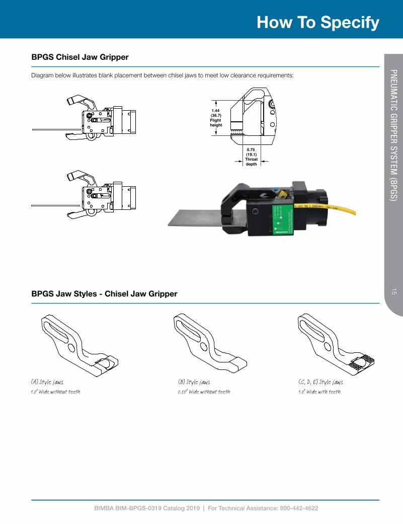
Chisel Jaw Grippers
Bimba's low profile chisel jaws fit into applications that require a low or tight clearance and are ideal for picking up flat work pieces. The 14° lower chisel jaw allows the gripper to accommodate for variation in part presentation.
BIMBA BIM-BPGS-0319 Catalog 2019 | For Technical Assistance: 800-442-4622
15
How To Specify15
PNEUM
ATIC GRIPPER SYSTEM (BPGS)
BPGS Chisel Jaw Gripper
Diagram below illustrates blank placement between chisel jaws to meet low clearance requirements:
1.44 (36.7)Flight height
0.75 (19.1)Throatdepth
(A) Style jaws1.0" Wide without teeth
(B) Style jaws0.50" Wide without teeth
(C, D, E) Style jaws1.0" Wide with teeth
1.44 (36.7)Flight height
0.75 (19.1)Throatdepth
BPGS Jaw Styles - Chisel Jaw Gripper
BIMBA BIM-BPGS-0319 Catalog 2019 | For Technical Assistance: 800-442-4622
16
How To Specify
16PN
EUMATIC GRIPPER SYSTEM
(BPGS)
A DIA 1/8" NPS or 1/8 Rc
Gripper closed
F
Gripper open
B
D
G
H
C
E
J
K
4X M5X0.8 0.52
1.20 (30.5)
0.60 (15.2)
0.60 (15.2)
1.20 (30.5)
1.41 (35.9)
1.29 (32.9)
1.52 (38.5)
1.41 (35.9)
1.39 (35.3)
1.52 (38.5)
1.60 (40.6)
1.32 (33.5)
1.49 (38)
1.60 (40.6)
1.48 (37.5)
1.49 (38)
2.04 (51.9)
1.55 (39.4)
1.16 (51.9)
2.04 (51.9)
1.37 (34.7)
1.16 (29.6)
Top view Side view Back view
22° X 0° 22° X 14°
45° X 0° 45° X 14°
70° X 0° 70° X 14°
Dimensions Inches mmA 1.73 43.9B 0.63 16.0C 5.24 133.1D 1.73 43.9E 1.25 31.8F 4.23 107.4G 1.18 29.8H 0.86 21.9J 1.18 30.0K 1.21 30.7
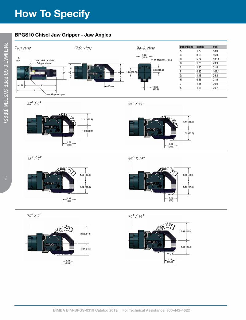
BPGS10 Chisel Jaw Gripper - Jaw Angles

BIMBA BIM-BPGS-0319 Catalog 2019 | For Technical Assistance: 800-442-4622
17
How To Specify17
PNEUM
ATIC GRIPPER SYSTEM (BPGS)
DADiameter
G
1/8" NPS or 1/8 RcGripper closed
Gripper open
1.41 (35.9)
1.29 (32.9)
H
FBC
1.52 (38.5)
4X M5X0.8 0.52
0.45 (11.4)
0.90 (22.9)
0.90 (22.9)
1.41 (35.9)
1.39 (35.3)
1.52 (38.5)
1.60 (40.6)
1.48 (37.5)
1.49 (38)
1.60 (40.6)
1.32 (33.5)
1.49 (38)
2.04 (51.9)
1.37 (34.7)
1.16 (29.6)
2.04 (51.9)
1.55 (39.4)
1.16 (51.9)
Dimensions Inches mmA 1.75 44.5B 1.50 38.1C 5.72 145.3D 2.00 50.8E 1.25 31.8F 4.23 170.4G 1.18 29.8H 1.00 25.4J 1.18 30.0K 1.21 30.7
Top view Side view Back view
22° X 0° 22° X 14°
45° X 0° 45° X 14°
70° X 0° 70° X 14°
BPGS11 Chisel Jaw Gripper - Jaw Angles

BIMBA BIM-BPGS-0319 Catalog 2019 | For Technical Assistance: 800-442-4622
18
How To Specify
18PN
EUMATIC GRIPPER SYSTEM
(BPGS)
Top
Left
0.50(12.7)
0.50(12.7)
0.50(12.7)
0.50(12.7)
1.00(25.4)
1.50(38.1)
Lower chisel jaw
“L1”
0.550-0.610(14.0-15.5)
1.00(25.4)
0.50(12.7)
0.50(12.7)
0.50(12.7)
1.00(25.4)
1.50(38.1)
0.50(12.7)
0.50(12.7)
0.50(12.7)
0.50(12.7)
1.00(25.4)
0.50(12.7)
Regular pads Double point pads
Smooth padsNo pads (NUL) Lower chisel jaw
Convex pads
Grip range with no pads
BPGS Jaw Pad - Chisel Jaw Gripper
Bottom
Right
BPGS Chisel Jaw Gripper - Port Orientation

BIMBA BIM-BPGS-0319 Catalog 2019 | For Technical Assistance: 800-442-4622
19
How to Order19
PNEUM
ATIC GRIPPER SYSTEM (BPGS)BPGS10B20DNR3S0E
Jaw Angle
20 22° x 0°
21 22° x 14°
40 45° x 0°
41 45° x 14°
70 70° x 0°
Body Style
10 Standard 1.20”x1.20” bolt pattern
11 Crossover 0.90”x0.90” bolt pattern
In Pad Sensor/Pad Type/Connector/Pad Mount/Body Mount
A Reg (0°)/ Micro M8/ Top / Right
B Reg (0°)/ Micro M8/ Top / Left
E Reg (0°)/ Pico M12 (Internal Wire) / Top / Right
F Reg (0°)/ Pico M12 (Internal Wire) / Top / Left
S Double Point / Micro M8 / Top / Right
T Double Point / Micro M8 / Top / Left
W Double Point / Pico M12 (Internal Wire) / Top / Right
Y Double Point / Pico M12 (Internal Wire) / Top / Left
I Smooth (0°) / Micro M8 / Top / Right
9 Smooth (0°) / Micro M8 / Top / Left
L No Sensor
Sensor Type
D Indirect double blank
H Indirect part present
I In-Pad
N No Sensor
Indirect Sensor
R Micro M8/Right
L Micro M8/Left
E Pico M12/Right
W Pico M12/Left
L No Sensor
Switch Output
N NPN
P PNP
2 2 Wire (3 Pin)4
T 2 Wire (4 Pin) 4,5
U No Sensor
Port Orientation
E Top 1/8” NPS
F Top 1/8” Rc
L Right 1/8” NPS
M Right 1/8” Rc
S Bottom 1/8” NPS
T Bottom 1/8” Rc
Z Left 1/8” NPS
2 Left 1/8” Rc
Pad Style
0 0°
D Double point6
S Smooth7
C Convex7
L No Pads
Pad Width
S 0.5”
M 1.0”
D 1.5”
U No Pads
Material Thickness
1 0.50-2.00mm
3 2.01-3.50mm
4 3.51-5.00mm
6 5.01-6.50mm
7 6.51-8.00mm
9 8.01-9.50mm
N No Pads
The model number for a chisel jaw gripper consists of an alphanumeric cluster designating the following below.
An example of a chisel jaw gripper with a standard body style, chisel jaw gripper at 22° x 0° angle, indirect double blank sensor, NPN switch, mounted on the right side with a M8 connector, for material between 2.01 and 3.5mm in thickness with 0.5” wide regular flat pads, with a port orientation of a top 1/8” NPS is shown below. See details below:
Jaw Angle
A Chisel (1.0” wide without teeth
B Chisel (0.5” wide without teeth)
C Chisel (1.0” wide with teeth)1
D Chisel (1.0” wide with teeth)2
E Chisel (1.0” wide with teeth)3
1 Use with Material Thickness 1 or 22 Use with Material Thickness 4 or 63 Use with Material Thickness 7 or 94 Only available with In-Pad 5Only available with In-Pad A,B,C,D6Cannot be used with “S” Pad width7Cannot be used with “D” Pad width

BIMBA BIM-BPGS-0319 Catalog 2019 | For Technical Assistance: 800-442-4622
Flange Jaw Grippers
Bimba's flange jaw grippers are mounted 90° to the work piece and allows the gripper to reach around a formed flange edge. The flange jaw gripper is a great choice for applications with no lift and/or panels that have a flange or projecting edge that can be used for gripping.

BIMBA BIM-BPGS-0319 Catalog 2019 | For Technical Assistance: 800-442-4622
21
How To Specify21
PNEUM
ATIC GRIPPER SYSTEM (BPGS)
BPGS Flange Jaw Gripper
Diagram below shows a flange gripper mounted 90° to a work piece:

BIMBA BIM-BPGS-0319 Catalog 2019 | For Technical Assistance: 800-442-4622
22
How To Specify
22PN
EUMATIC GRIPPER SYSTEM
(BPGS)
A DIA
1/8" NPS or 1/8 RcGripper closed
F
Gripper open
B
D
C E
G
H
0.60 (15.2)
0.60 (15.2)
1.20 (30.5)
1.75 (45)
1.22 (31)
1.85 (46.9)
J
K
4X M5X0.8 0.40
1.49 (37.8)
1.21 (30.7)
2.19 (55.5)
1.38 (35.1)
2.01 (51)
1.75 (44.5)
1.20 (30.5)
Top view Side view Back view
22° X 0°
45° X 0°
70° X 0°
Dimensions Inches mmA 1.73 43.8B 0.63 15.9C 5.40 137.2D 1.65 41.9E 1.41 35.8F 4.38 111.2G 1.18 29.8H 0.86 21.9J 1.18 29.9K 1.21 30.7
BPGS10 Flange Jaw Gripper - Jaw Angles

BIMBA BIM-BPGS-0319 Catalog 2019 | For Technical Assistance: 800-442-4622
23
How To Specify23
PNEUM
ATIC GRIPPER SYSTEM (BPGS)
1/8" NPS or 1/8 RcGripper closed
Gripper open
C
A Diameter
FB
D
4X M5X0.8 0.52
0.45 (11.4)
0.45 (11.4)0.90 (22.9)
0.90 (22.9)E
J
K
G
H
1.85 (46.9)
1.49 (37.1)
1.21 (30.8)
1.75 (45)
1.22 (31)
2.01 (51)
2.21 (56.2)
1.21 (30.8)
1.75 (44.5)
Top view Side view Back view
22° X 0°
45° X 0°
70° X 0°
Dimensions Inches mmA 1.73 44.5B 1.50 38.1C 5.89 149.6D 1.65 41.9E 1.41 35.8F 4.38 111.2G 1.18 29.8H 1 25.4J 1.18 29.9K 1.21 30.7
BPGS11 Flange Jaw Gripper - Jaw Angles

BIMBA BIM-BPGS-0319 Catalog 2019 | For Technical Assistance: 800-442-4622
24
How To Specify
24PN
EUMATIC GRIPPER SYSTEM
(BPGS)
Top
Left Right
Bottom
1.020 - 1.080(25.9 - 27.4)
Regular pads Double point pads Smooth pads Convex pads
Rubber padsAngular pads
Angled pad orientation No pads (NUL)
Code 1 (15° angle) Code 2, 4, 6
15º 30º 45º
Grip range with no pads
BPGS Jaw Pad - Flange Jaw Gripper
BPGS Flange Jaw Gripper - Port Orientation

BIMBA BIM-BPGS-0319 Catalog 2019 | For Technical Assistance: 800-442-4622
25
How to Order25
PNEUM
ATIC GRIPPER SYSTEM (BPGS)BPGS10F20DNR1M0E
Jaw Angle
20 22° x 0°
40 45° x 0°
70 70° x 0°
Body Style
10 Standard 1.20”x1.20” bolt pattern
11 Crossover 0.90”x0.90” bolt pattern
Jaw
F Flange
In Pad Sensor Pad Type/Connector/Pad Mount/Body Mount
A Reg (0°)/ Micro M8/ Top / Right
B Reg (0°)/ Micro M8/ Top / Left
C Reg (0°)/ Micro M8/ Bottom / Right
D Reg (0°)/ Micro M8/ Bottom / Left
E Reg (0°)/ Pico M12 (Internal Wire) / Top / Right
F Reg (0°)/ Pico M12 (Internal Wire) / Top / Left
G Reg (0°)/ Pico M12 (Internal Wire) / Bottom / Right
H Reg (0°)/ Pico M12 (Internal Wire) / Bottom / Left
K Reg (30°)/ Micro M8/ Top / Left
M Reg (30°)/ Micro M8/ Bottom / Left
P Reg (30°)/ Pico M12 (Internal Wire) / Top / Left
R Reg (30°)/ Pico M12 (Internal Wire) / Bottom / Left
T Double Point / Micro M8 / Top / Left
V Double Point / Micro M8 / Bottom / Left
W Double Point / Pico M12 (Internal Wire) / Top / Right
Y Double Point / Pico M12 (Internal Wire) / Top / Left
Z Double Point / Pico M12 (Internal Wire) / Bottom / Right
2 Double Point / Pico M12 (Internal Wire) / Bottom / Left
I Smooth (0°) / Micro M8 / Top / Right
9 Smooth (0°) / Micro M8 / Top / Left
3 Smooth (0°) / Micro M8 / Bottom / Right
4 Smooth (0°) / Micro M8 / Bottom / Left
6 Smooth (0°) / Micro M8 / Top / Left
8 Smooth (0°) / Micro M8 / Bottom / Left
L No Sensor
Sensor Type
D Indirect double blank
H Indirect part present
I In-Pad
N No Sensor
Indirect Sensor
R Micro M8/Right
L Micro M8/Left
E Pico M12/Right
W Pico M12/Left
L No Sensor
Switch Output
N NPN
P PNP
2 2 Wire (3 Pin)1
T 2 Wire (4 Pin) 1,2
U No Sensor
Port Orientation
E Top 1/8” NPS
F Top 1/8” Rc
L Right 1/8” NPS
M Right 1/8” Rc
S Bottom 1/8” NPS
T Bottom 1/8” Rc
Z Left 1/8” NPS
2 Left 1/8” Rc
Pad Style
0 0°
1 15° Forward slope
2 15° Rear slope
4 30° Rear slope
6 45° Rear slope
D Double point4
S Smooth5
C Convex5
R Rubber
L No Pads
Pad Width
S 0.5”3
M 1.0”3
D 1.5”6
U No Pads
Material Thickness
1 0.50-2.00mm
3 2.01-3.50mm
4 3.51-5.00mm
R 2.01-3.50mm
N No Pads
The model number for flange jaw gripper consists of an alphanumeric cluster designating the following below.
An example of a flange jaw gripper with a standard body style, flange jaw at 22° x 0° jaw angle, indirect double blank sensor, NPN switch, mounted on the right side with a M8 connector, for material between 0.5 and 2.0mm in thickness with 1.0” wide regular flat pads, with a port orientation of a top 1/8” NPS is shown below. See details below:
1 Only available with In-Pad2 Only available with In-Pad A,B,C,D3Cannot be used with “R” Pad width4Cannot be used with “S” Pad width5Cannot be used with “S” Pad width6Use with “R” Pad style
BIMBA BIM-BPGS-0319 Catalog 2019 | For Technical Assistance: 800-442-4622
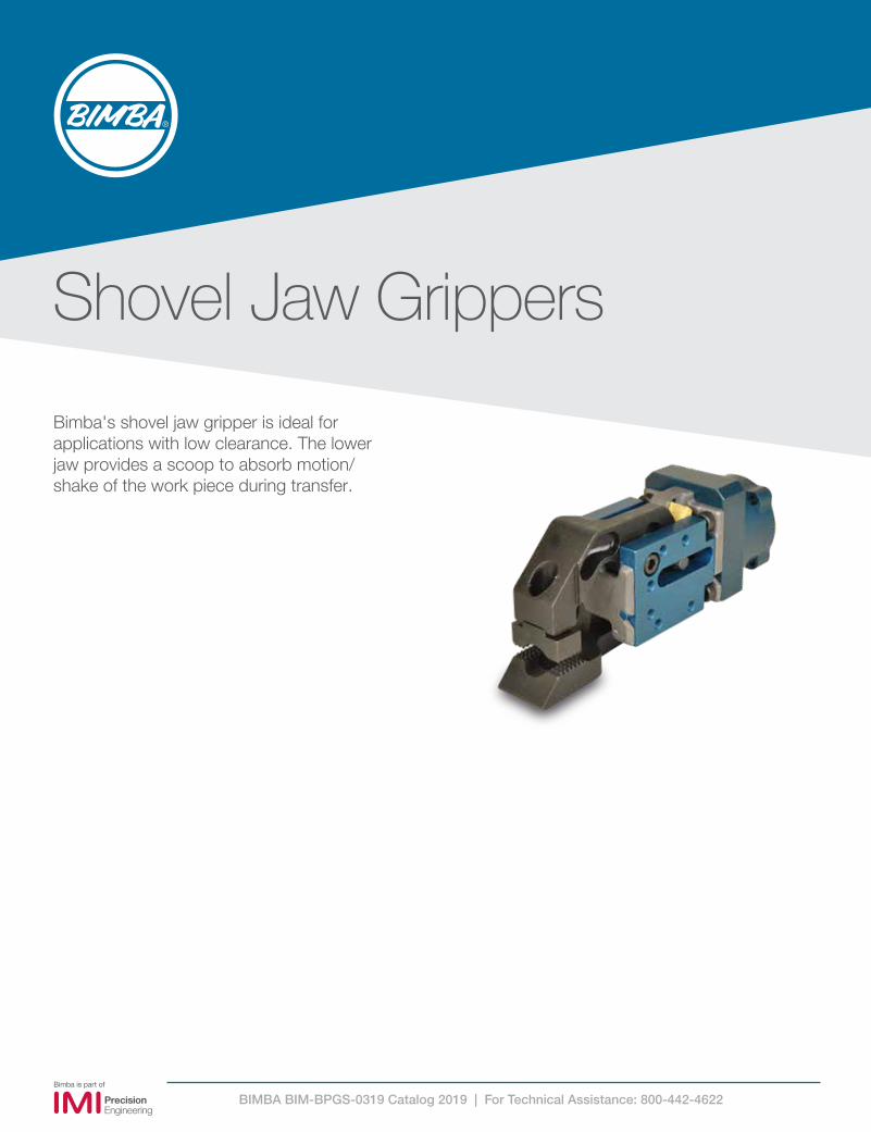
Shovel Jaw Grippers
Bimba's shovel jaw gripper is ideal for applications with low clearance. The lower jaw provides a scoop to absorb motion/shake of the work piece during transfer.

BIMBA BIM-BPGS-0319 Catalog 2019 | For Technical Assistance: 800-442-4622
27
How To Specify27
PNEUM
ATIC GRIPPER SYSTEM (BPGS)
BPGS Shovel Jaw Gripper
Diagram below illustrates blank placement using a shovel jaw gripper:
(S, T, U) Style jawsShovel jaw with teeth
(V, W, Y) Style jawsShovel jaw without teeth
BPGS Shovel Jaw Style
BIMBA BIM-BPGS-0319 Catalog 2019 | For Technical Assistance: 800-442-4622
28
How To Specify
28PN
EUMATIC GRIPPER SYSTEM
(BPGS)
4X M5 0.8 0.52
1.20 (30.5)
0.60 (15.2)1.20 (30.5)
0.60 (15.2)
1.19 (30)
1.15 (29)
1.44 (36)
1.20 (31)
2.05 (52)
1.37 (35)
A DIA
Note 2Gripper closed
F
Gripper open
B
D
C E
G
H
J
K
Note 1
22° X 0°
Top view Side view Back view
70° X 0°
45° X 0°
4X M5 0.8 0.52
1.20 (30.5)
0.60 (15.2)1.20 (30.5)
0.60 (15.2)
1.19 (30)
1.15 (29)
1.44 (36)
1.20 (31)
2.05 (52)
1.37 (35)
A DIA
Note 2Gripper closed
F
Gripper open
B
D
C E
G
H
J
K
Note 1
4X M5 0.8 0.52
1.20 (30.5)
0.60 (15.2)1.20 (30.5)
0.60 (15.2)
1.19 (30)
1.15 (29)
1.44 (36)
1.20 (31)
2.05 (52)
1.37 (35)
A DIA
Note 2Gripper closed
F
Gripper open
B
D
C E
G
H
J
K
Note 1 4X M5 0.8 0.52
1.20 (30.5)
0.60 (15.2)1.20 (30.5)
0.60 (15.2)
1.19 (30)
1.15 (29)
1.44 (36)
1.20 (31)
2.05 (52)
1.37 (35)
A DIA
Note 2Gripper closed
F
Gripper open
B
D
C E
G
H
J
K
Note 1
Dimensions Inches mmA 1.73 43.9B 0.63 16.0C 5.24 133.1D 1.73 43.9E 1.25 31.8F 4.23 107.4G 1.18 29.8H 0.86 21.9J 1.18 30.0K 1.21 30.7
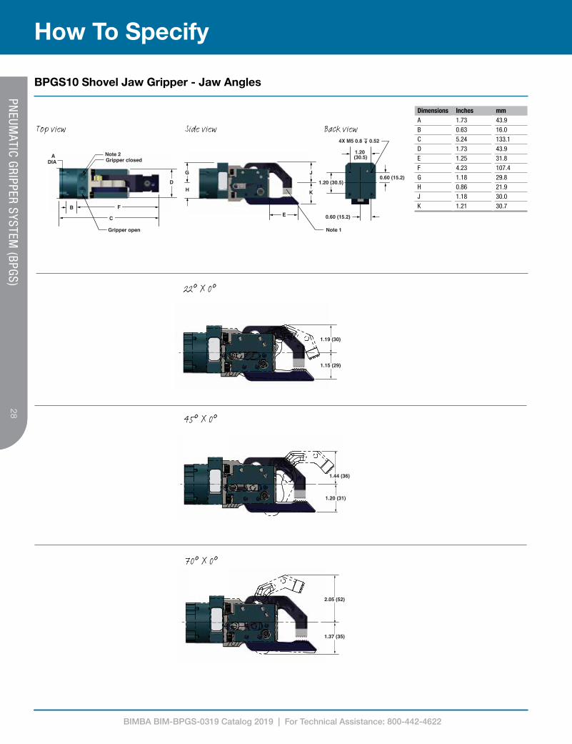
BPGS10 Shovel Jaw Gripper - Jaw Angles
BIMBA BIM-BPGS-0319 Catalog 2019 | For Technical Assistance: 800-442-4622
29
How To Specify29
PNEUM
ATIC GRIPPER SYSTEM (BPGS)
1.43 (36)
1.25 (32)
2.05 (52)
1.37 (35)
1.61 (41)
1.12 (28)
1.43 (36)
1.25 (32)
2.05 (52)
1.37 (35)
1.61 (41)
1.12 (28)
1.43 (36)
1.25 (32)
2.05 (52)
1.37 (35)
1.61 (41)
1.12 (28)
ADiameter D
F
B
C
Gripper open
Gripper close
Note 2
E
G
H
J
K
1.43 (36)
1.25 (32)
1.61 (41)
1.20 (31)
2.01 (51)
0.49(13)
4X M5X0.8 0.52
0.45 (11.4)
0.45 (11.4)0.90 (22.9)
0.90 (22.9)
Dimensions Inches mmA 1.75 43.8B 1.5 15.9C 6.14 143.5D 1.65 41.9E 1.64 42.2F 4.65 117.6G 1.18 29.8H 1 21.9J 1.16 28.1K 1.2 28.1
Note 1See page 34 for various gripper padsNote 21/8 NPS or 1/8 Rc
Top view Side view Back view
22° X 0°
45° X 0°
70° X 0°
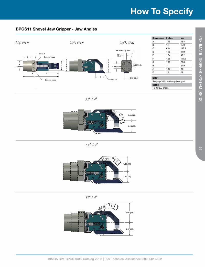
BPGS11 Shovel Jaw Gripper - Jaw Angles

BIMBA BIM-BPGS-0319 Catalog 2019 | For Technical Assistance: 800-442-4622
30
How To Specify
30PN
EUMATIC GRIPPER SYSTEM
(BPGS)
Top
Left Right
Bottom
0.50(12.7)
0.50(12.7)
0.50(12.7)
0.50(12.7)
0.50(12.7)
0.50(12.7)
1.00(25.4)
1.50(38.1)
1.00(25.4)
0.50(12.7)
Shovel jaw
“L1”
0.550-0.610(14.0-15.5)
0.50(12.7)
0.50(12.7)
0.50(12.7)
0.50(12.7)
0.50(12.7)
1.00(25.4)
1.50(38.1)
1.00(25.4)
Regular padsColor Material “L1” thicknessBlack 0.50 - 3.5Silver 3.51 - 6.5Gold 6.51 - 9.5
Double point pads
Smooth padsNo pads (NUL)Convex pads
Grip range with no pads
BPGS Jaw Pad - Shovel Jaw
BPGS Shovel Jaw Gripper - Port Orientation
BIMBA BIM-BPGS-0319 Catalog 2019 | For Technical Assistance: 800-442-4622
31
How to Order31
PNEUM
ATIC GRIPPER SYSTEM (BPGS)
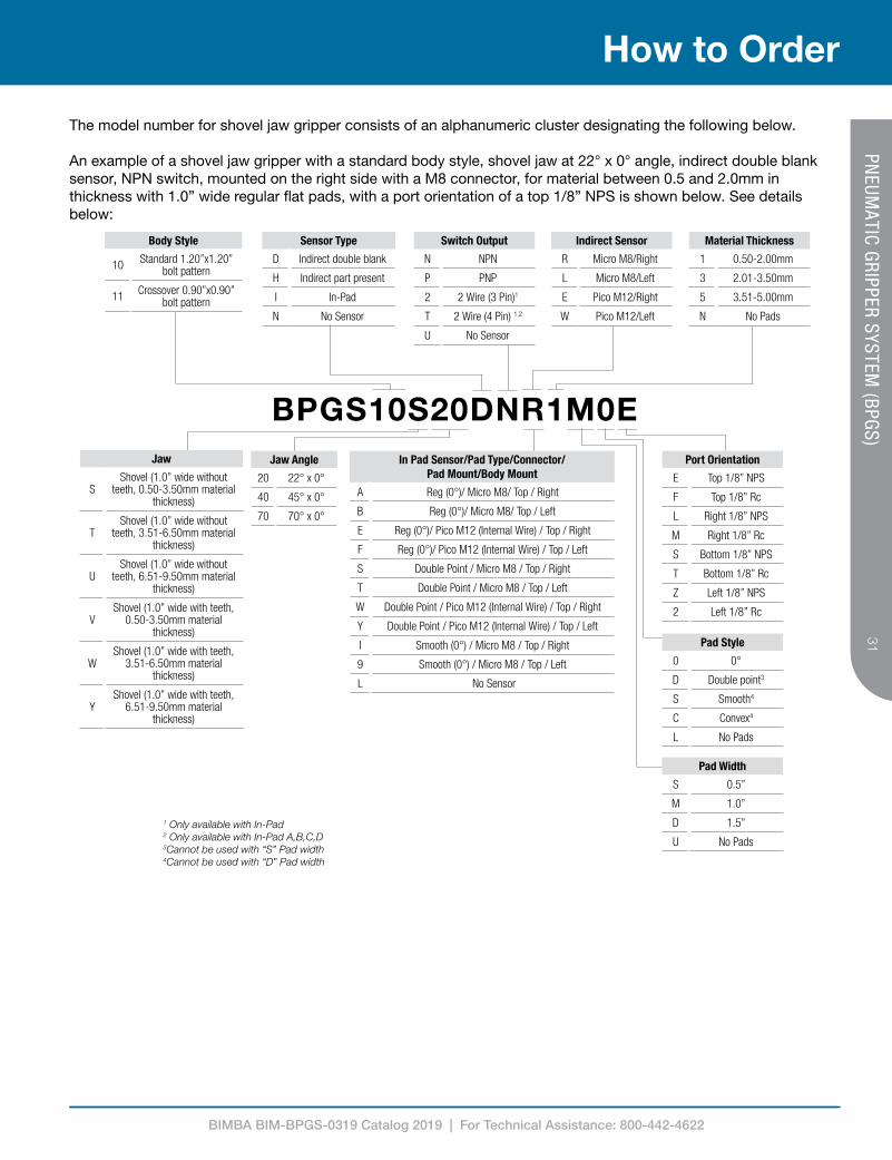
BPGS10S20DNR1M0EJaw Angle
20 22° x 0°
40 45° x 0°
70 70° x 0°
Body Style
10 Standard 1.20”x1.20” bolt pattern
11 Crossover 0.90”x0.90” bolt pattern
In Pad Sensor/Pad Type/Connector/Pad Mount/Body Mount
A Reg (0°)/ Micro M8/ Top / Right
B Reg (0°)/ Micro M8/ Top / Left
E Reg (0°)/ Pico M12 (Internal Wire) / Top / Right
F Reg (0°)/ Pico M12 (Internal Wire) / Top / Left
S Double Point / Micro M8 / Top / Right
T Double Point / Micro M8 / Top / Left
W Double Point / Pico M12 (Internal Wire) / Top / Right
Y Double Point / Pico M12 (Internal Wire) / Top / Left
I Smooth (0°) / Micro M8 / Top / Right
9 Smooth (0°) / Micro M8 / Top / Left
L No Sensor
Sensor Type
D Indirect double blank
H Indirect part present
I In-Pad
N No Sensor
Indirect Sensor
R Micro M8/Right
L Micro M8/Left
E Pico M12/Right
W Pico M12/Left
Switch Output
N NPN
P PNP
2 2 Wire (3 Pin)1
T 2 Wire (4 Pin) 1,2
U No Sensor
Port Orientation
E Top 1/8” NPS
F Top 1/8” Rc
L Right 1/8” NPS
M Right 1/8” Rc
S Bottom 1/8” NPS
T Bottom 1/8” Rc
Z Left 1/8” NPS
2 Left 1/8” Rc
Pad Style
0 0°
D Double point3
S Smooth4
C Convex4
L No Pads
Pad Width
S 0.5”
M 1.0”
D 1.5”
U No Pads
Material Thickness
1 0.50-2.00mm
3 2.01-3.50mm
5 3.51-5.00mm
N No Pads
Jaw
SShovel (1.0” wide without
teeth, 0.50-3.50mm material thickness)
TShovel (1.0” wide without
teeth, 3.51-6.50mm material thickness)
UShovel (1.0” wide without
teeth, 6.51-9.50mm material thickness)
VShovel (1.0” wide with teeth,
0.50-3.50mm material thickness)
WShovel (1.0” wide with teeth,
3.51-6.50mm material thickness)
YShovel (1.0” wide with teeth,
6.51-9.50mm material thickness)
The model number for shovel jaw gripper consists of an alphanumeric cluster designating the following below.
An example of a shovel jaw gripper with a standard body style, shovel jaw at 22° x 0° angle, indirect double blank sensor, NPN switch, mounted on the right side with a M8 connector, for material between 0.5 and 2.0mm in thickness with 1.0” wide regular flat pads, with a port orientation of a top 1/8” NPS is shown below. See details below:
1 Only available with In-Pad2 Only available with In-Pad A,B,C,D3Cannot be used with “S” Pad width4Cannot be used with “D” Pad width

BIMBA BIM-BPGS-0319 Catalog 2019 | For Technical Assistance: 800-442-4622
Angular Grippers
Bimba's angular grippers provide users the ability to bolt on custom jaws to the gripper. The angular grippers are ideal for flexible applications due to the ability to use custom jaws designed for your specific application.

BIMBA BIM-BPGS-0319 Catalog 2019 | For Technical Assistance: 800-442-4622
33
How To Specify33
PNEUM
ATIC GRIPPER SYSTEM (BPGS)
BPGS Angular Gripper

BIMBA BIM-BPGS-0319 Catalog 2019 | For Technical Assistance: 800-442-4622
34
How To Specify
34PN
EUMATIC GRIPPER SYSTEM
(BPGS)
BPGS Angular Gripper - Jaw Angles
Dimensions Inches mmA 1.73 43.8B 0.63 15.9C 4.62 117.3D 1.65 41.9E .64 16.1F 3.60 91.4G 1.18 29.8H .86 21.9J 1.10 27.9K 1.10 27.9
Side view Back viewTop view
22° x 0°22° x 11° 22° x 22°
45° x 0° 45° x 22° 45° x 45°
70° x 0° 70° x 35° 70° x 70°

BIMBA BIM-BPGS-0319 Catalog 2019 | For Technical Assistance: 800-442-4622
35
How To Specify35
PNEUM
ATIC GRIPPER SYSTEM (BPGS)
In order to achiev rated MCBD of million cycles, it is recommended that moment of inertia along Izz be less than -
For fully open jaws, Izz < 0.588 lbs.in2
For 45 opening, Izz < 0.882 lbs.in2
For 22 opening, Izz < 1.176 lbs.in2
This includes mounting hardware, pads and jaw extension.
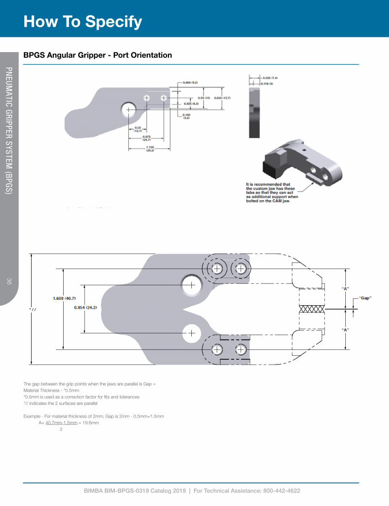
BPGS Angular Gripper - Port Orientation
BIMBA BIM-BPGS-0319 Catalog 2019 | For Technical Assistance: 800-442-4622
36
How To Specify
36PN
EUMATIC GRIPPER SYSTEM
(BPGS) The gap between the grip points when the jaws are parallel is Gap = Material Thickness - *0.5mm*0.5mm is used as a correction factor for fits and tolerances*// indicates the 2 surfaces are parallel
Example - For material thickness of 2mm, Gap is 2mm - 0.5mm=1.5mm A= 40.7mm-1.5mm = 19.6mm 2
BPGS Angular Gripper - Port Orientation

BIMBA BIM-BPGS-0319 Catalog 2019 | For Technical Assistance: 800-442-4622
37
How to Order37
PNEUM
ATIC GRIPPER SYSTEM (BPGS)
Jaw Angle
Z Angular
BPGS10 Z 77 NUL NUL E
The model number for z line jaw gripper consists of an alphanumeric cluster designating the jaw type and angle, and the port orientation.
An example of an angular jaw gripper with a standard body style, angular jaw at 70° x 70° angle, with a port orientation of a top 1/8” NPS is shown below. See details below:
Jaw Angle
20 22° x 0°
21 22° x 11°
22 22° x 22°
40 45° x 0°
42 45° x 22°
44 45° x 45°
70 70° x 0°
73 70° x 35°
77 70° x 70°
Port Orientation
E Top 1/8” NPS
F Top 1/8” Rc
L Right 1/8” NPS
M Right 1/8” Rc
S Bottom 1/8” NPS
T Bottom 1/8” Rc
Z Left 1/8” NPS
2 Left 1/8” Rc
No Sensor No Pad
Body Style
10 Standard 1.20”x1.20” bolt pattern
11 Crossover 0.90”x0.90” bolt pattern

BIMBA BIM-BPGS-0319 Catalog 2019 | For Technical Assistance: 800-442-4622
Hot Metal Regular Grippers
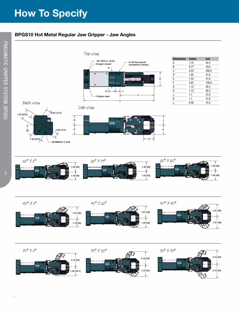
Bimba's Hot Metal Regular Grippers are designed to withstand temperatures up to 900°C. These grippers may be paired with a high temperature tooling system to protect plumbing and and electrical wiring from the heat, without the need for external heat wraps. The wide angle jaw opening can accomodate banks with inconsistent pick up location.

BIMBA BIM-BPGS-0319 Catalog 2019 | For Technical Assistance: 800-442-4622
39
How To Specify39
PNEUM
ATIC GRIPPER SYSTEM (BPGS)
BPGS10 Hot Metal Regular Gripper
Diagram below illustrates blank placement using a hot metal jaw gripper:
BIMBA BIM-BPGS-0319 Catalog 2019 | For Technical Assistance: 800-442-4622
40
How To Specify
40PN
EUMATIC GRIPPER SYSTEM
(BPGS)
1/8" NPS or 1/8 RcGripper closed
A
ø1.89 fits popularcompetitive clamps
D
B L
0.60 (15.2)
30º
4X M5X0.8 0.401.20 (30.5)
0.60 (15.2)
1.20 (30.5)
Gripper open
C
F
E
J
K
G
H
1.91 (48)
1.91 (48)
1.49 (38)
1.18 (30) 1.32 (33)
1.49 (38) 1.49 (38)
1.49 (38)
1.91 (48)
1.18 (30) 1.49 (38)
1.91 (48)
2.16 (55)2.16 (55)
1.36 (34.7) 1.73 (44)
2.16 (55)
2.16 (55)
Top view
Side viewBack view
22° X 0°
Dimensions Inches mmA 1.75 44.5B 0.77 19.6C 8.23 209.2D 1.65 41.9E 1.25 31.8F 3.97 100.8G 1.12 28.3H 1.12 28.3J 1.1 27.9K 1.1 27.9L 0.56 14.2
45° X 0°
70° X 0°
22° X 11°
45° X 22°
70° X 35°
22° X 22°
45° X 45°
70° X 70°
BPGS10 Hot Metal Regular Jaw Gripper - Jaw Angles
BIMBA BIM-BPGS-0319 Catalog 2019 | For Technical Assistance: 800-442-4622
41
How To Specify41
PNEUM
ATIC GRIPPER SYSTEM (BPGS)
1.020 - 1.080(25.9 - 27.4)
0.50(12.7)
0.50(12.7)
0.50(12.7)
0.50(12.7)
1.00(25.4)
1.50(38.1)
Lower chisel jaw
“L1”
0.550-0.610(14.0-15.5)
1.00(25.4)
0.50(12.7)
0.50(12.7)
0.50(12.7)
1.00(25.4)
1.50(38.1)
0.50(12.7)
0.50(12.7)
0.50(12.7)
0.50(12.7)
1.00(25.4)
0.50(12.7)
1.020 - 1.080(25.9 - 27.4)
1.020 - 1.080(25.9 - 27.4)
1.020 - 1.080(25.9 - 27.4)
0.50(12.7)
0.50(12.7)
0.50(12.7)
0.50(12.7)
1.00(25.4)
1.50(38.1)
Lower chisel jaw
“L1”
0.550-0.610(14.0-15.5)
1.00(25.4)
0.50(12.7)
0.50(12.7)
0.50(12.7)
1.00(25.4)
1.50(38.1)
0.50(12.7)
0.50(12.7)
0.50(12.7)
0.50(12.7)
1.00(25.4)
0.50(12.7)
0.50(12.7)
0.50(12.7)
0.50(12.7)
0.50(12.7)
1.00(25.4)
1.50(38.1)
Lower chisel jaw
“L1”
0.550-0.610(14.0-15.5)
1.00(25.4)
0.50(12.7)
0.50(12.7)
0.50(12.7)
1.00(25.4)
1.50(38.1)
0.50(12.7)
0.50(12.7)
0.50(12.7)
0.50(12.7)
1.00(25.4)
0.50(12.7)
Regular pads
No pads (NUL)
Grip range with no pads
BPGS10 Jaw Pad - Hot Metal Regular Jaw
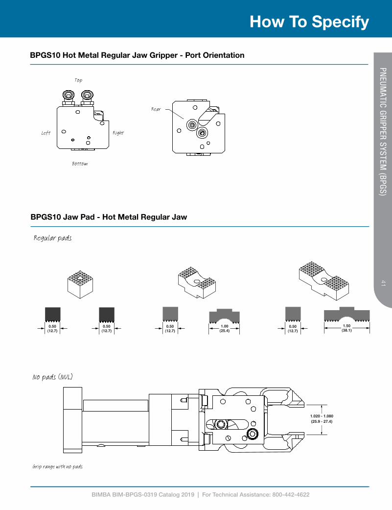
BPGS10 Hot Metal Regular Jaw Gripper - Port Orientation
Top
Bottom
RightLeft
Rear

BIMBA BIM-BPGS-0319 Catalog 2019 | For Technical Assistance: 800-442-4622
42
How To Specify
42PN
EUMATIC GRIPPER SYSTEM
(BPGS)
Telescope mount works with IMI Norgren Versa-link system PGS10TEL20 PGS10TEL40
Stud mountPGS10STD1.25 - 1.25" (31.8 mm)PGS10STD1.00 - 1.0" (25.4 mm)
Branch clampLLC2702
ø compatible with non- IMI Norgren branch clamp
Internal air/electricsIMI Norgren Versa-link system*PGS10TEL20P PGS10TEL20PM PGS10TEL40P PGS10TEL40PM
* Compatible with Pico sensors only
Indirect sensor
XS0 XM0 XD0
BPGS10 Jaw Pads - Flat Pads for General Purpose Gripping
1.020 - 1.080(25.9 - 27.4)
Regular pads
No pads (NUL)Grip range with no pads
0.50(12.7)
0.50(12.7)
0.50(12.7)
0.50(12.7)
1.00(25.4)
1.50(38.1)
Lower chisel jaw
“L1”
0.550-0.610(14.0-15.5)
1.00(25.4)
0.50(12.7)
0.50(12.7)
0.50(12.7)
1.00(25.4)
1.50(38.1)
0.50(12.7)
0.50(12.7)
0.50(12.7)
0.50(12.7)
1.00(25.4)
0.50(12.7)
1.020 - 1.080(25.9 - 27.4)
1.020 - 1.080(25.9 - 27.4)
1.020 - 1.080(25.9 - 27.4)
0.50(12.7)
0.50(12.7)
0.50(12.7)
0.50(12.7)
1.00(25.4)
1.50(38.1)
Lower chisel jaw
“L1”
0.550-0.610(14.0-15.5)
1.00(25.4)
0.50(12.7)
0.50(12.7)
0.50(12.7)
1.00(25.4)
1.50(38.1)
0.50(12.7)
0.50(12.7)
0.50(12.7)
0.50(12.7)
1.00(25.4)
0.50(12.7)
0.50(12.7)
0.50(12.7)
0.50(12.7)
0.50(12.7)
1.00(25.4)
1.50(38.1)
Lower chisel jaw
“L1”
0.550-0.610(14.0-15.5)
1.00(25.4)
0.50(12.7)
0.50(12.7)
0.50(12.7)
1.00(25.4)
1.50(38.1)
0.50(12.7)
0.50(12.7)
0.50(12.7)
0.50(12.7)
1.00(25.4)
0.50(12.7)

BIMBA BIM-BPGS-0319 Catalog 2019 | For Technical Assistance: 800-442-4622
43
How to Order43
PNEUM
ATIC GRIPPER SYSTEM (BPGS)BPGS10HR20DNR1D0E
Jaw Angle
20 22° x 0°
21 22° x 11°
22 22° x 22°
40 45° x 0°
42 45° x 22°
44 45° x 45°
70 70° x 0°
73 70° x 35°
77 70° x 70°
Body Style
10 Standard 1.20”x1.20” bolt pattern
Sensor Type
D Indirect double blank
H Indirect part present
C Open Closed
N No Sensor
Indirect Sensor
R Micro M8/Right
E Pico M12/Right
L No Sensor
Switch Output
N NPN
P PNP
U No Sensor
Port Orientation
E Top 1/8” NPS
F Top 1/8” Rc
L Right 1/8” NPS
M Right 1/8” Rc
S Bottom 1/8” NPS
T Bottom 1/8” Rc
Z Left 1/8” NPS
2 Left 1/8” Rc
7 Rear No Fittings1
Pad Style
0 0°
L No Pads
Pad Width
S 0.5”
M 1.0”
D 1.5”
U No Pads
Material Thickness
1 0.50-2.00mm
3 2.01-3.50mm
4 3.51-5.00mm
N No Pads
Jaw Angle
HR Hot Metal Regular
The model number for hot metal regular jaw gripper consists of an alphanumeric cluster designating the following below.
An example of a hot metal regular jaw gripper with a standard body style, regular jaw at 22° x 0° jaw angle, indirect double blank sensor, NPN switch, mounted on the right side with a M8 connector, for material between 0.5 and 2.0mm in thickness with 1.5” wide regular flat pads, with a port orientation of a top 1/8” NPS is shown below. See details below:
1 BPGS10TELXXPX not included
BIMBA BIM-BPGS-0319 Catalog 2019 | For Technical Assistance: 800-442-4622
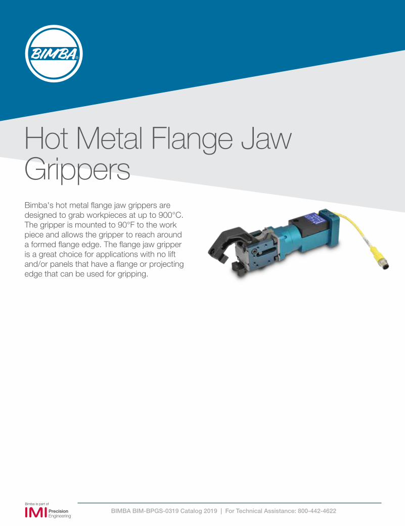
Hot Metal Flange Jaw GrippersBimba's hot metal flange jaw grippers are designed to grab workpieces at up to 900°C. The gripper is mounted to 90°F to the work piece and allows the gripper to reach around a formed flange edge. The flange jaw gripper is a great choice for applications with no lift and/or panels that have a flange or projecting edge that can be used for gripping.

BIMBA BIM-BPGS-0319 Catalog 2019 | For Technical Assistance: 800-442-4622
45
How To Specify45
PNEUM
ATIC GRIPPER SYSTEM (BPGS)
BPGS10 Hot Metal Flange Jaw Gripper
Diagram below illustrates blank placement using a hot metal flange jaw gripper:

BIMBA BIM-BPGS-0319 Catalog 2019 | For Technical Assistance: 800-442-4622
46
How To Specify
46PN
EUMATIC GRIPPER SYSTEM
(BPGS)
1/8" NPS or 1/8 Rc
Gripper closedA
ø1.89 fits popularcompetitive clamps
“D”
FGripper open
B
C
L
1.20 (30.5)
30º
1.20 (30.5)4X M5X0.8 0.40
0.60 (15.2)
0.60 (15.2)
E
J
K
G
H
1.49 (37.8)
1.21 (30.7)
1.85 (47)
2.01 (51)
1.75 (45)
1.22 (31)
2.19 (55.5)
1.38 (35.1)
1.75 (44.6)
Dimensions Inches mmA 1.75 44.5B 0.77 19.6C 8.39 213.2D 1.65 41.9E 1.41 35.8F 4.13 104.9G 1.12 28.3H 1.12 28.3J 1.18 29.9K 1.21 30.7L 0.56 14.2
22° X 0° 45° X 0°
70° X 0°
Top view
Back view Side view
BPGS10 Hot Metal Flange Jaw Gripper - Jaw Angles

BIMBA BIM-BPGS-0319 Catalog 2019 | For Technical Assistance: 800-442-4622
47
How To Specify47
PNEUM
ATIC GRIPPER SYSTEM (BPGS)
Telescope mount works with IMI Norgren Versa-link system PGS10TEL20 PGS10TEL40
Stud mountPGS10STD1.25 - 1.25" (31.8 mm)PGS10STD1.00 - 1.0" (25.4 mm)
Branch clampLLC2702
ø compatible with non- IMI Norgren branch clamp
Internal air/electricsIMI Norgren Versa-link system*PGS10TEL20P PGS10TEL20PM PGS10TEL40P PGS10TEL40PM
* Compatible with Pico sensors only
Indirect sensor
XS0 XM0 XD0
0.51 (12.9)Flange height
0.75 (19.1)Throatdepth
Top jaw
Bottom jaw
BPGS10 Jaw Pads - Flat Pads for General Purpose Gripping
BPGS10 Flange Height and Throat Depth
Top jaw
Bottom jaw
0.91 (23.1)Throatdepth
1.20 (30.4)Flange height
BIMBA BIM-BPGS-0319 Catalog 2019 | For Technical Assistance: 800-442-4622
48
How to Order
48PN
EUMATIC GRIPPER SYSTEM
(BPGS)
BPGS10HF20DNR1S0EJaw Angle
20 22° x 0°
40 45° x 0°
70 70° x 0°
Body Style
10 Standard 1.20”x1.20” bolt pattern
Sensor Type
D Indirect double blank
H Indirect part present
C Open Closed
N No Sensor
Indirect
R Micro M8/Right
L Micro M8/Left
E Pico M12/Right
W Pico M12/Left
L No Sensor
Switch Output
N NPN
P PNP
W No Sensor
Port Orientation
E Top 1/8” NPS
F Top 1/8” Rc
L Right 1/8” NPS
M Right 1/8” Rc
S Bottom 1/8” NPS
T Bottom 1/8” Rc
Z Left 1/8” NPS
2 Left 1/8” Rc
7 Rear No Fittings1
Pad Style
0 0°
L No Pads
Pad Width
S 0.5”
M 1.0”
D 1.5”
U No Pads
Material Thickness
1 0.50-2.00mm
3 2.01-3.50mm
4 3.51-5.00mm
Jaw Angle
HF Hot Metal Flange
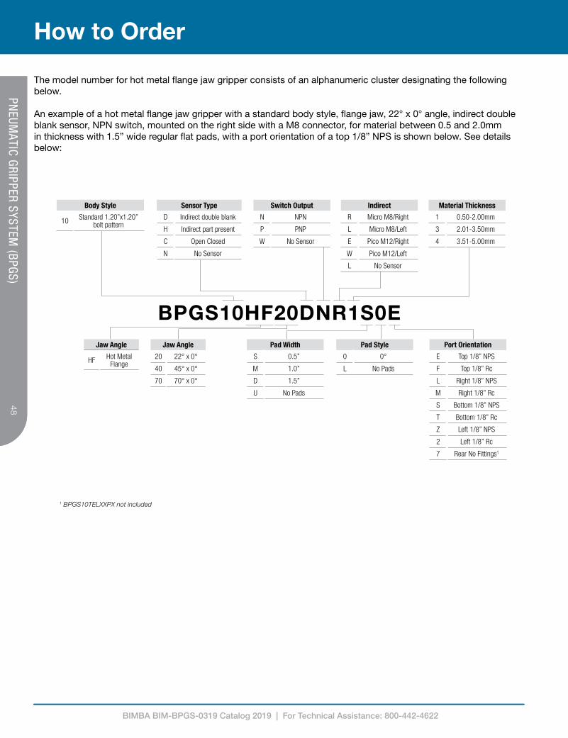
The model number for hot metal flange jaw gripper consists of an alphanumeric cluster designating the following below.
An example of a hot metal flange jaw gripper with a standard body style, flange jaw, 22° x 0° angle, indirect double blank sensor, NPN switch, mounted on the right side with a M8 connector, for material between 0.5 and 2.0mm in thickness with 1.5” wide regular flat pads, with a port orientation of a top 1/8” NPS is shown below. See details below:
1 BPGS10TELXXPX not included

BIMBA BIM-BPGS-0319 Catalog 2019 | For Technical Assistance: 800-442-4622
Accessories
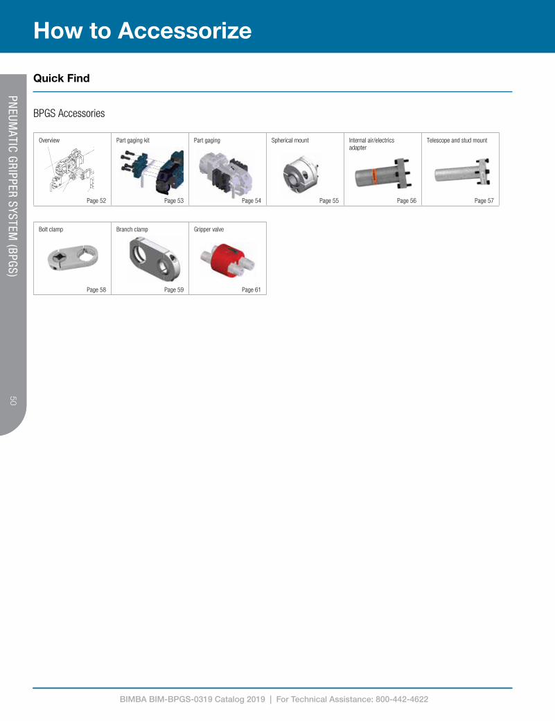
Bimba offers a wide range of accessories for the Pneumatic Gripper System such as part gaging kits, internal wiring mount adapters, telescope and stud mounts, rotational clamps, and gripper valves.
BIMBA BIM-BPGS-0319 Catalog 2019 | For Technical Assistance: 800-442-4622
50
How to Accessorize
50PN
EUMATIC GRIPPER SYSTEM
(BPGS)
Quick Find
BPGS Accessories
XM0XS0 XD0
XDXXMXXSX
XDD RDRXMD6 mm tube
1/8 Rc 1/8 Rc
8 mm tube
3/8 tube
1/8 NPT1/8 NPT
1/4 tube
PGS10TEL20 PGS10TEL40 PGS10STD1.25 - 1.25" (31.8 mm)
PGS10STD1.00 - 1.0" (25.4 mm)
PGS10CLP3B19SQ - Mates with 19 mm square tubePGS10CLP3B25SQ - Mates with 25 mm square tube
PGS10CLP3B1.00R - Mates with 1.00" (25.4 mm) tubePGS10CLP3B1.25R - Mates with 1.25" (31.8 mm) tube
Replaces side plate of gripper, cannot be used with part gaging
PGSGAGEXXCannot be used with indirect sensor
Telescope mount works with IMI Norgren Versa-link system
Branch clamp
Stud mount
In-pad sensor
Indirect sensor
Part gaging
Bolt clamp Branch clamp Gripper valve
Page 58 Page 59 Page 61
M5 X 8 mm bolts supplied for mounting in-pad sensor
Overview Part gaging kit Part gaging Spherical mount Internal air/electrics adapter
Telescope and stud mount
Page 52 Page 53 Page 54 Page 55 Page 56 Page 57

BIMBA BIM-BPGS-0319 Catalog 2019 | For Technical Assistance: 800-442-4622
51
How to Accessorize51
PNEUM
ATIC GRIPPER SYSTEM (BPGS)
Dimensions in inches (mm) are for reference only
These accessories apply to all non-hot metal versions of the BPGS10 Pneumatic Gripper Series
BPGS10TEL20 BPGS10TEL40
BPGS10CLP3B19SQ - Mates with 19 mm square tubeBPGS10CLP3B25SQ - Mates with 25 mm square tube
BPGS10CLP3B1.00R - Mates with 1.00 (25.4) tubeBPGS10CLP3B1.25R - Mates with 1.25 (31.8) tube
BPGS10CLP3B25RD - Mates with .984 (25) tubeReplaces side plate of gripper
Can not be used with part gauging
BPGSGAGEXXCannot be used with Indirect Sensor
BPGS10TEL100WRG
BPGS10CLPSP19SQ - Mates with 19 mm square tubeBPGS10CLPSP25SQ - Mates with 25 mm square tube
BPGS10CLPSP1.00R - Mates with 1.00 (25.4) tubeBPGS10CLPSP1.25R - Mates with 1.25 (31.8) tubeBPGS10CLPSP25RD - Mates with 0.984 (25) tube
BSGV10XGripper Valve
Part Gauging
BPGS10STD1.25 - 1.25 (31.8)BPGS10STD1.00 - 1.0 (25.4)
Stud mount
Internal wire gripper mount adapter
Telescope mount works
Spherical ball clamp
Branch clamp In-pad sensor
Double blank or part present indirect sensor
BPGS Accessories

BIMBA BIM-BPGS-0319 Catalog 2019 | For Technical Assistance: 800-442-4622
52
How to Accessorize
52PN
EUMATIC GRIPPER SYSTEM
(BPGS)
These accessories apply to the BPGS10 hot metal grippers: regular (BPGS10HR) and flange (BPGS10HF) hot metal jaw gripper
BPGS10TEL20 BPGS10TEL40
BLLC2702
compatible with non- Bimba branch clamp
BPGS10TEL20P BPGS10TEL20PM BPGS10TEL40P BPGS10TEL40PM
BPGS10CLPSP19SQ - Mates with 19 mm square tubeBPGS10CLPSP25SQ - Mates with 25 mm square tube
BPGS10CLPSP1.00R - Mates with 1.00 (25.4) tubeBPGS10CLPSP1.25R - Mates with 1.25 (31.8) tube
BPGS10CLPSP25RD - Mates with 0.984 (25) tube
BSGV10X
Double blank or part present indirect sensor
Internal wire gripper mount adapter works with IMI Norgren Versa-link system
Stud mountBPGS10STD1.25 - 1.25 (31.8)BPGS10STD1.00 - 1.0 (25.4)
Branch clamp
Internal wire gripper mount adapter for hot metal BPGS grippers
* Compatible with Pico sensors only
Gripper valve
Spherical ball clamp
Dimensions in inches (mm) are for reference only
BPGS10 Hot Metal Gripper Accessories

BIMBA BIM-BPGS-0319 Catalog 2019 | For Technical Assistance: 800-442-4622
53
How to Accessorize53
PNEUM
ATIC GRIPPER SYSTEM (BPGS) M5 X 8 mm bolts supplied
for mounting in-pad sensor
M5 X 8 mm bolts supplied for mounting in-pad sensor
Qty. Description2 Clamps plates2 Rods8 SHCS (M5 X 12)2 SHCS (M5 X 8)*
*Bolts to mount in-pad sensor in place
Part number DescriptionBPGSGAGE90D30LA Aluminum clamp plates - part straightening for regular gripperBPGSGAGE90D30LS Steel clamp plates - part straightening for regular gripperBPGSGAGECHSL14A Aluminum clamp plates - easy part release for 14° chisel gripperBPGSGAGECHSL14S Steel clamp plates - easy part release for 14° chisel gripperBPGSGAGEFLGU45A Aluminum clamp plates - easy part release for 45° flange gripperBPGSGAGEFLGU45S Steel clamp plates - easy part release for 45° flange gripperBPGSGAGEFLGU70A Aluminum clamp plates - easy part release for 70° flange gripperBPGSGAGEFLGU70S Steel clamp plates - easy part release for 70° flange gripper
Rod is still accessible to unlock jaws Use a small blunt object to push rod forward to unlock jaws
Apply removable thread checker (e.g. LoctiteTM 242) to boltsLoosely assemble clamp platesPlace gage rod in desired position Tighten bolts evenly to 72 in-lb (8.1 Nm)Ensure that gaging plates are parallel to gripper side plate when fully torqued
Adhesive Tool TorqueRemovable thread checker (e.g. LoctiteTM 242) 4 mm hex key 72 in-lb (8.1 Nm)
Part Gaging for BPGS
Assembly Instructions
Part Gaging Kit Contents
Needed for Assembly

BIMBA BIM-BPGS-0319 Catalog 2019 | For Technical Assistance: 800-442-4622
54
How to Accessorize
54PN
EUMATIC GRIPPER SYSTEM
(BPGS)
BPGSGAGEFLGU45SBPGSGAGEFLGU45A
BPGS10F40XXXXXXX45º only
BPGSGAGEFLGU70SBPGSGAGEFLGU70A
BPGS10F70XXXXXXX70º only
BPGSGAGECHSL14SBPGSGAGECHSL14A
BPGS10CX1XXXXXXX14º only
After gripper releases part,rod allows part to be removed from gripper easily withoutcatching pad.
Part with flangebeing transferred
Can be used to prevent parts from hanging up on the gripper when the part is released
Allows parts to be straightenedbefore gripper closes
CORRECTED PART
OUT OF PLACE PART
Can be used to correct part orientation as gripper moves in
0.48 (12.3)2.61 (66.4)
Typical all for all gaging
Part number Gripper Clamp plate material
Weight lb (kg)
BPGSGAGE90D30LS Regular Steel 0.650 (.29)BPGSGAGE90D30LA Regular Aluminum 0.300 (.14)BPGSGAGECHSL14S Chisel Steel 0.670 (.30)BPGSGAGECHSL14A Chisel Aluminum 0.320 (.14)BPGSGAGEFLGU45S Flange Steel 0.680 (.31)BPGSGAGEFLGU45A Flange Aluminum 0.330 (.15)BPGSGAGEFLGU70S Flange Steel 0.680 (.31)BPGSGAGEFLGU70A Flange Aluminum 0.330 (.15)
• Used with BPGS series grippers for easy part removal• Rods can be moved in several different positions• Rods can be custom made per customer specifications to stabilize parts during
transfer• Can be used to position parts
Note: Gaging can be used with in-pad sensors.
Gaging can NOT be used with indirect sensors.
Part Gaging for BPGS - BPGSGAGEXX
Technical Data

BIMBA BIM-BPGS-0319 Catalog 2019 | For Technical Assistance: 800-442-4622
55
How to Accessorize55
PNEUM
ATIC GRIPPER SYSTEM (BPGS)
25mm Round
2.29 (58.17)
1.69 (42.93)
30°
1.00" Round
1.25" Round
19mm Square
25mm Square
2X M8 X 25mm
2X M6 X 12mm
2.88 (73.15)
2X M6 X 45mm
4X M5 X 12mm
• BPGS10CLPSPXXXX accomodates 1.00" round, 1.25" round,
25 mm round,19 mm square & 25 mm square tubes• Spherical ball clamp allows 360° rotation and 30° of angular adjustment
Part number WeightBPGS10CLPSP1.00R 1.35 lbs (0.61 kg)BPGS10CLPSP1.25R 1.21 lbs (0.55 kg)BPGS10CLPSP25RD 1.35 lbs (0.61 kg)BPGS10CLPSP19SQ 1.37 lbs (0.62 kg)BPGS10CLPSP25SQ 1.26 lbs (0.57 kg)
Spherical Mount - BPGS10CLPSPXXXX
Technical Data
Dimensions in inches (mm) are for reference only

BIMBA BIM-BPGS-0319 Catalog 2019 | For Technical Assistance: 800-442-4622
56
How to Accessorize
56PN
EUMATIC GRIPPER SYSTEM
(BPGS)
B
A
NOTE 1
CD
NOTE 2
Dimensions in inches (mm) are for reference only
Internal Wire Gripper Mount Adapter - BPGS10TEL100WRG
Technical Data
BPGS10TEL100WRGDim mm InchesøA 29.4 1.16B 100.0 3.94C 59.4 2.34D 30.5 1.20
Dim WeightBPGS10TEL100WRG 0.322 lbs / 146 g
Note 1
Slot allows Pico style sensor to enter finger
Note 2Adapter Bolt size for mounting
BPGS10TEL100WRG 4X M5 X 20
• Provides telescoping adjustment of gripper position
• Provides entry point for Pico style sensor cable into finger • Telescoping O.D. sized for insertion into standard Bimba 1.25” O.D. finger link or tubing

BIMBA BIM-BPGS-0319 Catalog 2019 | For Technical Assistance: 800-442-4622
57
How to Accessorize57
PNEUM
ATIC GRIPPER SYSTEM (BPGS)
Note 2Adapter Bolt size for mounting
BPGS10TEL100WRG 4X M5 X 20
0.46(11.7)
BPGS10STDXXXX
0.60(15.2)
0.60(15.2)
1.65(41.9)
1.20(30.5)
1.20(30.5)
1.65(41.9) “A”
4.00(101.6)
BPGS10STDXXXX
• BPGS10STDXXXX provide mounting stud compatible with various diameter tooling components
Technical Data
Telescope & Stud Mounts for BPGS10 Series - BPGS10STDXX, BPGS10TELX
Substitute Feature Weight1.00 ø1.0” X 4” Long 0.400 lbs / 180 g1.08 ø1.08” X 4” Long 0.400 lbs / 180 g1.25 ø1.25” X 4” Long 0.410 lbs / 185 g
25MM ø25 mm X 4” Long 0.250 lbs / 115 g30MM ø30 mm X 4” Long 0.260 lbs / 120 g
BPGS10STDXXXXø “A”
Inch mm0.984 251.00 25.41.08 27.41.181 30

BIMBA BIM-BPGS-0319 Catalog 2019 | For Technical Assistance: 800-442-4622
58
How to Accessorize
58PN
EUMATIC GRIPPER SYSTEM
(BPGS)
5.13 (130.3)
“B”
0.19 (4.8)“A”3X M8X1.25X25 mm SHCS
1.00 (25.4)0.75 (19.1)
30º 2.87 (73)
1.00" Round 25 mm Round
1.25" Round
19 mm Square
25 mm Square
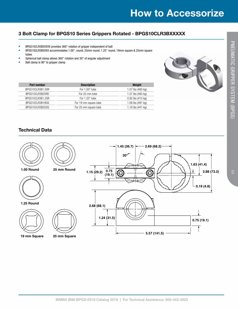
• BPGS10CLX3BXXXXX provides 360º rotation of gripper independent of ball• BPGS10CLX3BXXXXX accommodates 1.00" round, 1.25" round, 19 mm square, 25 mm square tubes and 25 mm
round• Spherical ball clamp allows 360º rotation and 30º angular adjustment
Technical Data
3 Bolt Clamp for BPGS10 Series - BPGS10CLX3BXXXXX
Part number Description WeightBPGS10CLP3B1.00R 57.2 mm center to center for 1.00 tube 0.93 lbs / 422 gBPGS10CLP3B1.25R 57.2 mm center to center for 1.25 tube 0.78 lbs / 352 gBPGS10CLP3B19SQ 57.2 mm center to center for 19 mm tube 0.94 lbs / 428 gBPGS10CLP3B25SQ 57.2 mm center to center for 25 mm tube 0.84 lbs / 378 gBPGS10CLP3B25RD 57.2 mm center to center for 25 mm tube 1.03 lbs / 468 gBPGS10CLT3B1.00R 79.5 mm center to center for 1.00 tube 1.21 lbs / 549 gBPGS10CLT3B1.25R 79.5 mm center to center for 1.25 tube 1.07 lbs / 485 gBPGS10CLT3B19SQ 79.5 mm center to center for 19 mm tube 1.23 lbs / 560 gBPGS10CLT3B25SQ 79.5 mm center to center for 25 mm tube 1.13 lbs / 511 gBPGS10CLT3B25RD 79.5 mm center to center for 25 mm tube 1.21 lbs / 552 g
Part family “A” “B”BPGS10CLP3BXXXX 2.25 (57.2) 2.26 (57.4)BPGS10CLT3BXXXX 3.13 (79.5) 3.14 (79.8)
BIMBA BIM-BPGS-0319 Catalog 2019 | For Technical Assistance: 800-442-4622
59
How to Accessorize59
PNEUM
ATIC GRIPPER SYSTEM (BPGS)
Part number Description WeightBPGS10CLR3B1.00R For 1.00" tube 1.07 lbs (485 kg)BPGS10CLR3B25RD For 25 mm tube 1.07 lbs (485 kg)BPGS10CLR3B1.25R For 1.25" tube 0.92 lbs (415 kg)BPGS10CLR3B19SQ For 19 mm square tube 1.08 lbs (491 kg)BPGS10CLR3B25SQ For 25 mm square tube 1.16 lbs (441 kg)
• BPGS10CLR3BXXXXX provides 360° rotation of gripper independent of ball• BPGS10CLR3BXXXX accommodates 1.00", round, 25mm round, 1.25" round, 19mm square & 25mm square
tubes• Spherical ball clamp allows 360° rotation and 30° of angular adjustment• Ball clamp is 90° to gripper clamp
5.57 (141.5)
0.75 (19.1)1.24 (31.5)
25 mm Round
2.68 (68.1)
1.00 Round
1.25 Round
19 mm Square 25 mm Square
0.75(19.1)
1.15 (29.2)
30°
2.69 (68.2)1.45 (36.7)
1.63 (41.4)
2.88 (73.2)
0.19 (4.8)
5.57 (141.5)
0.75 (19.1)1.24 (31.5)
25 mm Round
2.68 (68.1)
1.00 Round
1.25 Round
19 mm Square 25 mm Square
0.75(19.1)
1.15 (29.2)
30°
2.69 (68.2)1.45 (36.7)
1.63 (41.4)
2.88 (73.2)
0.19 (4.8)
Technical Data
3 Bolt Clamp for BPGS10 Series Grippers Rotated - BPGS10CLR3BXXXXX

BIMBA BIM-BPGS-0319 Catalog 2019 | For Technical Assistance: 800-442-4622
60
How to Accessorize
60PN
EUMATIC GRIPPER SYSTEM
(BPGS)
5.38 (136.55)
ø 1.75 (44.5)
2.94 (74.70)
1.47 (37.34)
1.15 (29.21)
0.75 (19.05)
30º
2.67 (67.82)1.47 (37.34)
2.68 (68.07)
1.24 (31.50)
0.75 (19.05)
Weight: 1.11 lbs/502 g
90 ° rotated LLC2302R Branch Clamp
BPGS11CLT3B19SQ
BPGS11CLT3B25SQ
BPGS11CLP3B1.25R
BPGS11CLT3B1.00R
• Used to mount BPGS10H and BPGS11 series grippers to 25mm OD branch link tubing, or stud• Spherical ball clamp allows 360° rotation and 30° of angular adjustment
Part number Description WeightBLLC2302R 1.75" Branch clamp to 90° rotated 25mm spherical
clamp1.11 lbs (0.502 kg)
Technical Data
1.75” Branch Clamp to 25mm Spherical Clamp Rotated - BLLC2302R
Dimensions in inches (mm) are for reference only

BIMBA BIM-BPGS-0319 Catalog 2019 | For Technical Assistance: 800-442-4622
61
How to Accessorize61
PNEUM
ATIC GRIPPER SYSTEM (BPGS)
• Redirects air from the gripper “closed” air port to the gripper “open” air port• “Vents” or shuts air off to a single gripper without turning air off the entire system• Mounts in-line with grippers or rail receivers• Easily release incorrectly gripped panels
BSGV10X
Note: Air port threadsare 1/8" NPT type
1.00" assembled (25.4)
“L”
ø 1.38 type (35.1)
Shown with fittingfor 1/4" hose
Shown with fittingfor 3/8" hose
1.52 (38.6) maxwith 3/8" fitting
Note: Air port threadsare 1/8" NPT type
1.00" assembled (25.4)
“L”
ø 1.38 type (35.1)
Shown with fittingfor 1/4" hose
Shown with fittingfor 3/8" hose
1.52 (38.6) maxwith 3/8" fitting
Technical Data
BPGS Gripper Valve - BSGV100, 102, 103
Dimensions in inches (mm) are for reference only
Part number Air fitting “L” WeightBSVG100 None
1.32 gramsBSVG102 1/4” push type 2.21 (56.1 mm)BSVG103 3/8” push type 2.76 (70.1 mm)
Air fitting CodeNone 0
1/4“ push type 23/8“ push type 3

BIMBA BIM-BPGS-0319 Catalog 2019 | For Technical Assistance: 800-442-4622
Reconfigurable Kits
Bimba offers a wide variety of reconfigurable kits since our grippers take less than one minute to repair or reconfigure. Our grippers can be easily repaired by using a single wrench reducing downtime for your operations.
BIMBA BIM-BPGS-0319 Catalog 2019 | For Technical Assistance: 800-442-4622
63
How to Accessorize63
PNEUM
ATIC GRIPPER SYSTEM (BPGS)
S
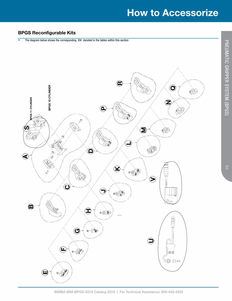
• The diagram below shows the corresponding ID# denoted in the tables within this section
VU
SA
BP
GS
11
CY
LIN
DE
R
BP
GS
10
CY
LIN
DE
R
B
CF
E
G
H
J
D
P
R
QN
M
L
VU
K
BPGS Reconfigurable Kits
BIMBA BIM-BPGS-0319 Catalog 2019 | For Technical Assistance: 800-442-4622
64
How to Accessorize
64PN
EUMATIC GRIPPER SYSTEM
(BPGS)
ID# Gripper Part number Description Color
S BPGS1010144 1/8" NPS air ports Blue10144-01 1/8 Rc air ports Black
Cylinders
C
D
E
F
H
L
N
PGS10 CYLINDER ASSEMBLY
P
R
PGS11 CYLINDER ASSEMBLY ECN DESCRIPTION
RRH
RRH
RRH
INDIRECT SENSOR KITPART # OUTPUT CONNECTOR SENSOR TYPE
NPNNPNPNPPNPNPNNPNNPNNPNPNPPNPPNPPNP
CYLINDERSGRIPPER PART # DESCRIPTION COLOR
AIR FITTINGSPART # DESCRIPTION THREAD CYLINDER
PNPPNPPNPPNPPNPPNPPNPPNPPNPPNPPNPPNPPNPPNPPNPPNPNPNNPNNPNNPNNPNNPNNPNNPNNPNNPN
Part number Output Connector Sensor type
BSGS40040-K NPN Micro Double blankBSGS40040P4-K NPN Pico 4 pin (Internal wire) Double blankBSGS40041-K PNP Micro Double blankBSGS40041P4-K PNP Pico 4 pin (Internal wire) Double blankBSGG40042-K NPN Micro Part presentBSGS40042P-K NPN Pico 3 pin (Internal wire) Part presentBSGS40042F-K NPN Micro Part presentBSGS40042FP-K NPN Pico 3 pin (Internal wire) Part presentBSGS40043-K PNP Micro Part presentBSGS40043P-K PNP Pico 3 pin (Internal wire) Part presentBSGS40043F-K PNP Micro Part presentBSGS40043FP-K PNP Micro Part presentBSGS40034KC 2 Wire Micro Part present
Indirect Sensor Kits
Flange jaw
C
D
E
F
H
L
N
PGS10 CYLINDER ASSEMBLY
P
R
PGS11 CYLINDER ASSEMBLY ECN DESCRIPTION
RRH
RRH
RRH
INDIRECT SENSOR KITPART # OUTPUT CONNECTOR SENSOR TYPE
NPNNPNPNPPNPNPNNPNNPNNPNPNPPNPPNPPNP
CYLINDERSGRIPPER PART # DESCRIPTION COLOR
AIR FITTINGSPART # DESCRIPTION THREAD CYLINDER
PNPPNPPNPPNPPNPPNPPNPPNPPNPPNPPNPPNPPNPPNPPNPPNPNPNNPNNPNNPNNPNNPNNPNNPNNPNNPN
Part number Output Connector Material thickness Pad type
BSGS40034KS 2 Wire Micro 4 pin 1 key 0.5-3.5 mm Regular
BSGS40034KG 2 Wire Micro 4 pin 1 key 2.01-5.0 mm Regular
BSGS40021KS 2 Wire Micro 3 pin 2 key 0.5-3.5 mm Single point
BSGS40021KG 2 Wire Micro 3 pin 2 key 2.01-5.0 mm Single point
BSGS40020KS 2 Wire Micro 3 pin 2 key 0.5-3.5 mm Regular
BSGS40020KG 2 Wire Micro 3 pin 2 Key 2.01-5.0 mm Regular
BSGS40020PKS 2 Wire Pico (Internal wire) 0.5-3.5 mm Regular
BSGS40020PKG 2 Wire Pico (Internal wire) 2.01-5.0 mm Regular
BSGS40020KS-30 2 Wire Micro 3 pin 2 Key 0.5-3.5 mm 30º
BSGS40020-S-KS 2 Wire Micro 3 pin 2 Key 0.5-3.5 mm Smooth (0°)
BSGS40020-S-KG 2 Wire Micro 3 pin 2 Key 2.01-5.0 mm Smooth (0°)
BSGS40020-30-S-KS 2 Wire Micro 3 pin 2 Key 0.5-3.5 mm Smooth (30°)
BSGS40020-30-S-KG 2 Wire Micro 3 pin 2 Key 2.01-5.0 mm Smooth (30°)
BSGS40034KS 2 Wire Micro 4 pin 1 key 2.01-3.50 mm Regualr
BSGS40034KC 2 Wire Micro 4 pin 1 key 0.5-2.00 mm Regular
BSGS40034KG 2 Wire Micro 4 pin 1 key 3.51-5.0 mm Regular
BSGS40034KO 2 Wire Micro 4 pin 1 key 5.01-6.50 mm Regular
BSGS40015KS PNP Micro 4 pin 1 key 0.5-3.5 mm Regular
BSGS40015KG PNP Micro 4 pin 1 key 2.01-5.0 mm Regular
BSGS40015PKS PNP Pico (Internal wire) 0.5-3.5 mm Regular
BSGS40015PKG PNP Pico (Internal wire) 2.01-5.0 mm Regular
BSGS40015KS-30 PNP Micro 4 pin 1 key 0.5-3.5 mm 30º
BSGS40015KG-30 PNP Micro 4 pin 1 key 2.01-5.0 mm 30º
BSGS40015PKS-30 PNP Pico (Internal wire) 0.5-3.5 mm 30º
BSGS40015PKG-30 PNP Pico (Internal wire) 2.01-5.0 mm 30º
BSGS40015-DPKS PNP Micro 4 pin 1 key 0.5-3.5 mm Double point
BSGS40015-DPKG PNP Micro 4 pin 1 key 2.01-5.0 mm Double point
BSGS40015P-DPKS PNP Pico (Internal wire) 0.5-3.5 mm Double point
BSGS40015P-DPKG PNP Pico (Internal wire) 2.01-5.0 mm Double point
BSGS40015-S-KS PNP Micro 4 pin 1 key 0.5-3.5 mm Smooth (0°)
BSGS40015-S-KG PNP Micro 4 pin 1 key 2.01-5.0 mm Smooth (0°)
BSGS40015-30-S-KS PNP Micro 4 pin 1 key 0.5-3.5 mm Smooth (30°)
BSGS40015-30-S-KG PNP Micro 4 pin 1 key 2.01-5.0 mm Smooth (30°)
BSGS40014KS NPN Micro 4 pin 1 key 0.5-3.5 mm Regular
BSGS40014KG NPN Micro 4 Pin 1 key 2.01-5.0 mm Regular
BSGS40014PKS NPN Pico (Internal wire) 0.5-3.5 mm Regular
BSGS40014PKG NPN Pico (Internal wire) 2.01-5.0 mm Regular
BSGS40014KS-30 NPN Micro 4 pin 1 key 0.5-3.5 mm 30º
BSGS40014KG-30 NPN Micro 4 pin 1 key 2.01-5.0 mm 30º
BSGS40014PKS-30 NPN Pico (Internal wire) 0.5-3.5 mm 30º
BSGS40014PKG-30 NPN Pico (Internal wire) 2.01-5.0 mm 30º
BSGS40014-S-KS NPN Micro 4 pin 1 key 0.5-3.5 mm Smooth (0°)
BSGS40014-S-KG NPN Micro 4 pin 1 key 2.01-5.0 mm Smooth (0°)
BSGS40014-30-S-KS NPN Micro 4 pin 1 key 0.5-3.5 mm Smooth (30°)
BSGS40014-30-S-KG NPN Micro 4 pin 1 key 2.01-5.0 mm Smooth (30°)
In-Pad Sensor Kits
In-pad sensor
Indirect sensor
Sensors, Air Cylinders, and Air Fittings Kit
BIMBA BIM-BPGS-0319 Catalog 2019 | For Technical Assistance: 800-442-4622
65
How to Accessorize65
PNEUM
ATIC GRIPPER SYSTEM (BPGS)
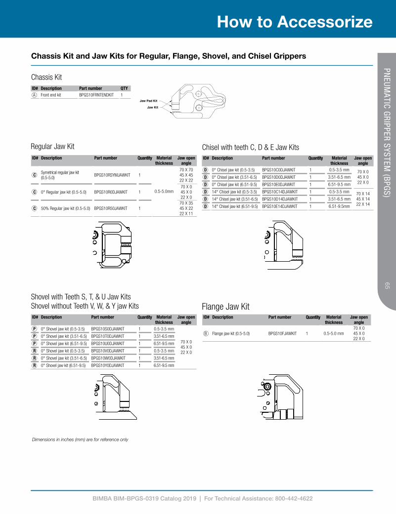
ID# Description Part number QTY A Front end kit BPGS10FRNTENDKIT 1
ID# Description Part number Quantity Material thickness
Jaw open angle
B Flange jaw kit (0.5-5.0) BPGS10FJAWKIT 1 0.5-5.0 mm70 X 045 X 022 X 0
ID# Description Part number Quantity Material thickness
Jaw open angle
C Symetrical regular jaw kit (0.5-5.0) BPGS10RSYMJAWKIT 1
0.5-5.0mm
70 X 7045 X 4522 X 22
C 0° Regular jaw kit (0.5-5.0) BPGS10R0DJAWKIT 170 X 045 X 022 X 0
C 50% Regular jaw kit (0.5-5.0) BPGS10R50JAWKIT 170 X 3545 X 2222 X 11
Flange Jaw Kit
Regular Jaw KitID# Description Part number Quantity Material
thicknessJaw open
angle D 0° Chisel jaw kit (0.5-3.5) BPGS10C0DJAWKIT 1 0.5-3.5 mm 70 X 0
45 X 0 22 X 0
D 0° Chisel jaw kit (3.51-6.5) BPGS10D0DJAWKIT 1 3.51-6.5 mm
D 0° Chisel jaw kit (6.51-9.5) BPGS10E0DJAWKIT 1 6.51-9.5 mm
D 14° Chisel jaw kit (0.5-3.5) BPGS10C14DJAWKIT 1 0.5-3.5 mm 70 X 14 45 X 14 22 X 14
D 14° Chisel jaw kit (3.51-6.5) BPGS10D14DJAWKIT 1 3.51-6.5 mm
D 14° Chisel jaw kit (6.51-9.5) BPGS10E14DJAWKIT 1 6.51-9.5mm
Chisel with teeth C, D & E Jaw Kits
ID# Description Part number Quantity Material thickness
Jaw open angle
P 0° Shovel jaw kit (0.5-3.5) BPGS10S0DJAWKIT 1 0.5-3.5 mm
70 X 045 X 0 22 X 0
P 0° Shovel jaw kit (3.51-6.5) BPGS10T0DJAWKIT 1 3.51-6.5 mm
P 0° Shovel jaw kit (6.51-9.5) BPGS10U0DJAWKIT 1 6.51-9.5 mm
R 0° Shovel jaw kit (0.5-3.5) BPGS10V0DJAWKIT 1 0.5-3.5 mm
R 0° Shovel jaw kit (3.51-6.5) BPGS10W0DJAWKIT 1 3.51-6.5 mm
R 0° Shovel jaw kit (6.51-9.5) BPGS10Y0DJAWKIT 1 6.51-9.5 mm
Shovel with Teeth S, T, & U Jaw KitsShovel without Teeth V, W, & Y jaw Kits
Chassis Kit
1015010151
11102 11103 11022
11104 11105 11026
11104 12978 12985
Jaw Pad Kit
Jaw Kit
Shovel jaw pad kit
Shovel jaw kit
Chassis Kit and Jaw Kits for Regular, Flange, Shovel, and Chisel Grippers
Dimensions in inches (mm) are for reference only

BIMBA BIM-BPGS-0319 Catalog 2019 | For Technical Assistance: 800-442-4622
66
How to Accessorize
66PN
EUMATIC GRIPPER SYSTEM
(BPGS)
1.50 (38.1) 0.50(12.7)
0.50(12.7)
0.50(12.7)
1.00 (25.4)
1.50 (38.1)
1.00 (25.4)
1.50 (38.1)
0.50(12.7)
0.50(12.7)
0.50(12.7)
0.50(12.7)
1.00 (25.4) 0.50(12.7)
0.50(12.7)
0.50(12.7)
0.50(12.7)
0.50(12.7)
0.50(12.7)
0.50(12.7)
1.00 (25.4)
1.00 (25.4)
Chisel or Shovel Jaw Pads 0.5" (12.7 mm) Wide
Chisel or Shovel Jaw Pads 1.0" (25.4 mm) Wide
Chisel or Shovel Jaw Pads 1.5" (38.1 mm) Wide
1.50 (38.1) 0.50(12.7)
0.50(12.7)
0.50(12.7)
1.00 (25.4)
1.50 (38.1)
1.00 (25.4)
1.50 (38.1)
0.50(12.7)
0.50(12.7)
0.50(12.7)
0.50(12.7)
1.00 (25.4) 0.50(12.7)
0.50(12.7)
0.50(12.7)
0.50(12.7)
0.50(12.7)
0.50(12.7)
0.50(12.7)
1.00 (25.4)
1.00 (25.4)
1.50 (38.1) 0.50(12.7)
0.50(12.7)
0.50(12.7)
1.00 (25.4)
1.50 (38.1)
1.00 (25.4)
1.50 (38.1)
0.50(12.7)
0.50(12.7)
0.50(12.7)
0.50(12.7)
1.00 (25.4) 0.50(12.7)
0.50(12.7)
0.50(12.7)
0.50(12.7)
0.50(12.7)
0.50(12.7)
0.50(12.7)
1.00 (25.4)
1.00 (25.4)
NOTES: 1. Chisel and shovel jaw grippers only have upper jaw pads. 2. Angled pads cannot be used with chisel or shovel jaw grippers.
LKR1068SS1LKR1068SS2
LKR1068MS1LKR1068MS2
BLKR1068DS1BLKR1068DS2
Material thickness when used with specified jawID# Part number Kit description Black jaw Silver jaw Gold jaw
H BLKR1068SS1 1 Black pad with shim 0.50 - 2.0 mm 3.51 - 5.0 mm 6.51 - 8.0 mm
H BLKR1068SS2 1 Silver pad 2.01 - 3.5 mm 5.01 -6.5 mm 8.01 - 9.5 mm
Material thickness when used with specified jawID# Part number Kit description Black jaw Silver jaw Gold jaw
J BLKR1068MS1 1 Black pad with shim 0.50 - 2.0 mm 3.51 - 5.0 mm 6.51 - 8.0 mm
J BLKR1068MS2 1 Silver pad 2.01 - 3.5 mm 5.01 -6.5 mm 8.01 - 9.5 mm
Material thickness when used with specified jawID# Part number Kit description Black jaw Silver jaw Gold jaw
K BLKR1068DS1 1 Black pad with shim 0.50 - 2.0 mm 3.51 - 5.0 mm 6.51 - 8.0 mm
K BLKR1068DS2 1 Silver pad 2.01 - 3.5 mm 5.01 -6.5 mm 8.01 - 9.5 mm
Chisel and Shovel Jaw Pad Kits

BIMBA BIM-BPGS-0319 Catalog 2019 | For Technical Assistance: 800-442-4622
67
How to Accessorize67
PNEUM
ATIC GRIPPER SYSTEM (BPGS)
BLKR1050MP1BLKR1050MP2BLKR1050MP3
BLKR1050DP1BLKR1050DP2BLKR1050DP3
1.50 (38.1) 0.50(12.7)
0.50(12.7)
0.50(12.7)
1.00 (25.4)
1.50 (38.1)
1.00 (25.4)
1.50 (38.1)
0.50(12.7)
0.50(12.7)
0.50(12.7)
0.50(12.7)
1.00 (25.4) 0.50(12.7)
0.50(12.7)
0.50(12.7)
0.50(12.7)
0.50(12.7)
0.50(12.7)
0.50(12.7)
1.00 (25.4)
1.00 (25.4)
ID# Part Number DescriptionM BLKR1050MP1 Material thickness 0.5-2.0 mm
M BLKR1050MP2 Material thickness 2.01-3.5 mm
M BLKR1050MP3 Material thickness 3.51-5.0 mm
ID# Part Number DescriptionN BLKR1050DP1 Material thickness 0.5-2.0 mm
N BLKR1050DP2 Material thickness 2.01-3.5 mm
N BLKR1050DP3 Material thickness 3.51-5.0 mm
Non-Angled Double Point Pads 1.0" (25.4 mm) Widths
ID# Part number DescriptionQ BLKR10501SC Material thickness 0.5-2.0 mm
Q BLKR10503SC Material thickness 2.01-3.5 mm
Q BLKR10504SC Material thickness 3.51-5.0 mm
ID# Part number DescriptionQ BLKR10501MC Material thickness 0.5-2.0 mm
Q BLKR10503MC Material thickness 2.01-3.5 mm
Q BLKR10504MC Material thickness 3.51-5.0 mm
Convex Pads 0.5" (12.7 mm) & 1.0" (25.4 mm) Widths
ID# Part number DescriptionQ BLKR10501MC-MS Material thickness 0.5-2.0 mm
Q BLKR10503MC-MS Material thickness 2.01-3.5 mm
Q BLKR10504MC-MS Material thickness 3.51-5.0 mm
1.50 (38.1) 0.50(12.7)
0.50(12.7)
0.50(12.7)
1.00 (25.4)
1.50 (38.1)
1.00 (25.4)
1.50 (38.1)
0.50(12.7)
0.50(12.7)
0.50(12.7)
0.50(12.7)
1.00 (25.4) 0.50(12.7)
0.50(12.7)
0.50(12.7)
0.50(12.7)
0.50(12.7)
0.50(12.7)
0.50(12.7)
1.00 (25.4)
1.00 (25.4)
1.50 (38.1) 0.50(12.7)
0.50(12.7)
0.50(12.7)
1.00 (25.4)
1.50 (38.1)
1.00 (25.4)
1.50 (38.1)
0.50(12.7)
0.50(12.7)
0.50(12.7)
0.50(12.7)
1.00 (25.4) 0.50(12.7)
0.50(12.7)
0.50(12.7)
0.50(12.7)
0.50(12.7)
0.50(12.7)
0.50(12.7)
1.00 (25.4)
1.00 (25.4)
1.50 (38.1) 0.50(12.7)
0.50(12.7)
0.50(12.7)
1.00 (25.4)
1.50 (38.1)
1.00 (25.4)
1.50 (38.1)
0.50(12.7)
0.50(12.7)
0.50(12.7)
0.50(12.7)
1.00 (25.4) 0.50(12.7)
0.50(12.7)
0.50(12.7)
0.50(12.7)
0.50(12.7)
0.50(12.7)
0.50(12.7)
1.00 (25.4)
1.00 (25.4)
Convex- Smooth Pads 0.5" (12.7 mm)
1.50 (38.1) 0.50(12.7)
0.50(12.7)
0.50(12.7)
1.00 (25.4)
1.50 (38.1)
1.00 (25.4)
1.50 (38.1)
0.50(12.7)
0.50(12.7)
0.50(12.7)
0.50(12.7)
1.00 (25.4) 0.50(12.7)
0.50(12.7)
0.50(12.7)
0.50(12.7)
0.50(12.7)
0.50(12.7)
0.50(12.7)
1.00 (25.4)
1.00 (25.4)
BLKR10501SCBLKR10503SCBLKR10504SC
BLKR10501MC BLKR10503MCBLKR10504MC
BLKR10501MC-MSBLKR10503MC-MSBLKR10504MC-MS
Non-Angled Double Point Pads 1.5" (38.1 mm) Widths
Convex 1.0" (25.4 mm) Widths
Regular and Flange Jaw Pad Kits
Dimensions in inches (mm) are for reference only
BIMBA BIM-BPGS-0319 Catalog 2019 | For Technical Assistance: 800-442-4622
68
How to Accessorize
68PN
EUMATIC GRIPPER SYSTEM
(BPGS)
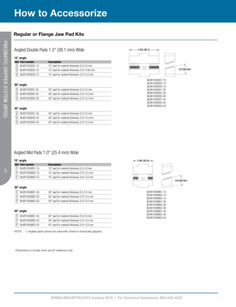
ID# Part number DescriptionF BLKR1050MS1-15 15° pad for material thickness 0.5-2.0 mm
F BLKR1050MS2-15 15° pad for material thickness 2.01-3.5 mm
F BLKR1050MS3-15 15° pad for material thickness 3.51-5.0 mm
F BLKR1050MS1-30 30° pad for material thickness 0.5-2.0 mm
F BLKR1050MS2-30 30° pad for material thickness 2.01-3.5 mm
F BLKR1050MS3-30 30° pad for material thickness 3.51-5.0 mm
F BLKR1050MS1-45 45° pad for material thickness 0.5-2.0 mm
F BLKR1050MS2-45 45° pad for material thickness 2.01-3.5 mm
F BLKR1050MS3-45 45° pad for material thickness 3.51-5.0 mm
ID# Part number DescriptionE BLKR1050DS1-15 15° pad for material thickness 0.5-2.0 mm
E BLKR1050DS2-15 15° pad for material thickness 2.01-3.50 mm
E BLKR1050DS3-15 15° pad for material thickness 3.51-5.0 mm
E BLKR1050DS1-30 30° pad for material thickness 0.5-2.0 mm
E BLKR1050DS2-30 30° pad for material thickness 2.01-3.5 mm
E BLKR1050DS3-30 30° pad for material thickness 3.51-5.0 mm
E BLKR1050DS1-45 45° pad for material thickness 0.5-2.0 mm
E BLKR1050DS2-45 45° pad for material thickness 2.01-3.5 mm
E BLKR1050DS3-45 45° pad for material thickness 3.51-5.0 mm
NOTES: UNLESS OTHERWISE SPECIFIED
1.50 (38.1)
LKR1050DSX-XX
15º/30º/45º
15º/30º/45º
LKR1050MSX-XX
1.00 (25.4)
LKR1050SSX-XX
45º/30º/15º
0.50(12.7)
LKR1050SSX
0.50(12.7)
0.50(12.7)
LKR1050MSX
LKR1050DSX
1.00 (25.4)0.50
(12.7)
Pads continueon page 4
1.50 (38.1)0.50
(12.7)
NOTE: 1. Angled pads cannot be used with chisel or shovel jaw grippers.
Angled Mid Pads 1.0" (25.4 mm) Wide
Angled Double Pads 1.5" (38.1 mm) Wide
NOTES: UNLESS OTHERWISE SPECIFIED
1.50 (38.1)
LKR1050DSX-XX
15º/30º/45º
15º/30º/45º
LKR1050MSX-XX
1.00 (25.4)
LKR1050SSX-XX
45º/30º/15º
0.50(12.7)
LKR1050SSX
0.50(12.7)
0.50(12.7)
LKR1050MSX
LKR1050DSX
1.00 (25.4)0.50
(12.7)
Pads continueon page 4
1.50 (38.1)0.50
(12.7)
BLKR1050DS1-15BLKR1050DS2-15BLKR1050DS3-15BLKR1050DS1-30BLKR1050DS2-30BLKR1050DS3-30BLKR1050DS1-45BLKR1050DS2-45BLKR1050DS3-45
BLKR1050MS1-15BLKR1050MS2-15BLKR1050MS3-15BLKR1050MS1-30BLKR1050MS2-30BLKR1050MS3-30BLKR1050MS1-45BLKR1050MS2-45BLKR1050MS3-45
30° angle
15° angle
45° angle
30° angle
15° angle
45° angle
Regular or Flange Jaw Pad Kits
Dimensions in inches (mm) are for reference only

BIMBA BIM-BPGS-0319 Catalog 2019 | For Technical Assistance: 800-442-4622
69
How to Accessorize69
PNEUM
ATIC GRIPPER SYSTEM (BPGS)
NOTES: UNLESS OTHERWISE SPECIFIED
1.50 (38.1)
LKR1050DSX-XX
15º/30º/45º
15º/30º/45º
LKR1050MSX-XX
1.00 (25.4)
LKR1050SSX-XX
45º/30º/15º
0.50(12.7)
LKR1050SSX
0.50(12.7)
0.50(12.7)
LKR1050MSX
LKR1050DSX
1.00 (25.4)0.50
(12.7)
Pads continueon page 4
1.50 (38.1)0.50
(12.7)
NOTES: 1. Angled pads cannot be used with chisel or shovel jaw grippers.
ID# Part number DescriptionG BLKR1050SS1-15 15° pad for material thickness 0.5-2.0 mm
G BLKR1050SS2-15 15° pad for material thickness 2.01-3.5 mm
G BLKR1050SS3-15 15° pad for material thickness 3.51-5.0 mm
G BLKR1050SS1-30 30° pad for material thickness 0.5-2.0 mm
G BLKR1050SS2-30 30° pad for material thickness 2.01-3.5 mm
G BLKR1050SS3-30 30° pad for material thickness 3.51-5.0 mm
G BLKR1050SS1-45 45° pad for material thickness 0.5-2.0 mm
G BLKR1050SS2-45 45° pad for material thickness 2.01-3.5 mm
G BLKR1050SS3-45 45° pad for material thickness 3.51-5.0 mm
Angled Single Pads 0.5" (12.7 mm) Wide
BLKR1050SS1-15BLKR1050SS2-15BLKR1050SS3-15BLKR1050SS1-30BLKR1050SS2-30BLKR1050SS3-30BLKR1050SS1-45BLKR1050SS2-45BLKR1050SS3-45
30° angle
15° angle
45° angle
NOTES: UNLESS OTHERWISE SPECIFIED
1.50 (38.1)
LKR1050DSX-XX
15º/30º/45º
15º/30º/45º
LKR1050MSX-XX
1.00 (25.4)
LKR1050SSX-XX
45º/30º/15º
0.50(12.7)
LKR1050SSX
0.50(12.7)
0.50(12.7)
LKR1050MSX
LKR1050DSX
1.00 (25.4)0.50
(12.7)
Pads continueon page 4
1.50 (38.1)0.50
(12.7)
NOTES: UNLESS OTHERWISE SPECIFIED
1.50 (38.1)
LKR1050DSX-XX
15º/30º/45º
15º/30º/45º
LKR1050MSX-XX
1.00 (25.4)
LKR1050SSX-XX
45º/30º/15º
0.50(12.7)
LKR1050SSX
0.50(12.7)
0.50(12.7)
LKR1050MSX
LKR1050DSX
1.00 (25.4)0.50
(12.7)
Pads continueon page 4
1.50 (38.1)0.50
(12.7)
NOTES: UNLESS OTHERWISE SPECIFIED
1.50 (38.1)
LKR1050DSX-XX
15º/30º/45º
15º/30º/45º
LKR1050MSX-XX
1.00 (25.4)
LKR1050SSX-XX
45º/30º/15º
0.50(12.7)
LKR1050SSX
0.50(12.7)
0.50(12.7)
LKR1050MSX
LKR1050DSX
1.00 (25.4)0.50
(12.7)
Pads continueon page 4
1.50 (38.1)0.50
(12.7)
ID# Part number DescriptionH BLKR1050SS1 Material thickness 0.5-2.0 mm
H BLKR1050SS2 Material thickness 2.01-3.5 mm
H BLKR1050SS3 Material thickness 3.51-5.0 mm
ID# Part number DescriptionJ BLKR1050MS1 Material thickness 0.5-2.0 mm
J BLKR1050MS2 Material thickness 2.01-3.5 mm
J BLKR1050MS3 Material thickness 3.51-5.0 mm
ID# Part number DescriptionK BLKR1050DS1 Material thickness 0.5-2.0 mm
K BLKR1050DS2 Material thickness 2.01-3.5 mm
K BLKR1050DS3 Material thickness 3.51-5.0 mm
BLKR1050SS1BLKR1050SS2BLKR1050SS3
BLKR1050MS1BLKR1050MS2BLKR1050MS3
BLKR1050DS1BLKR1050DS2BLKR1050DS3
Non-Angled Single Pads 0.5" (12.7 mm) Wide
Non-angled Mid Pads 1.0" (25.4 mm) Wide
Non-Angled Double Pads 1.5" (38.1 mm) Wide
Regular or Flange Jaw Pad Kits
Dimensions in inches (mm) are for reference only
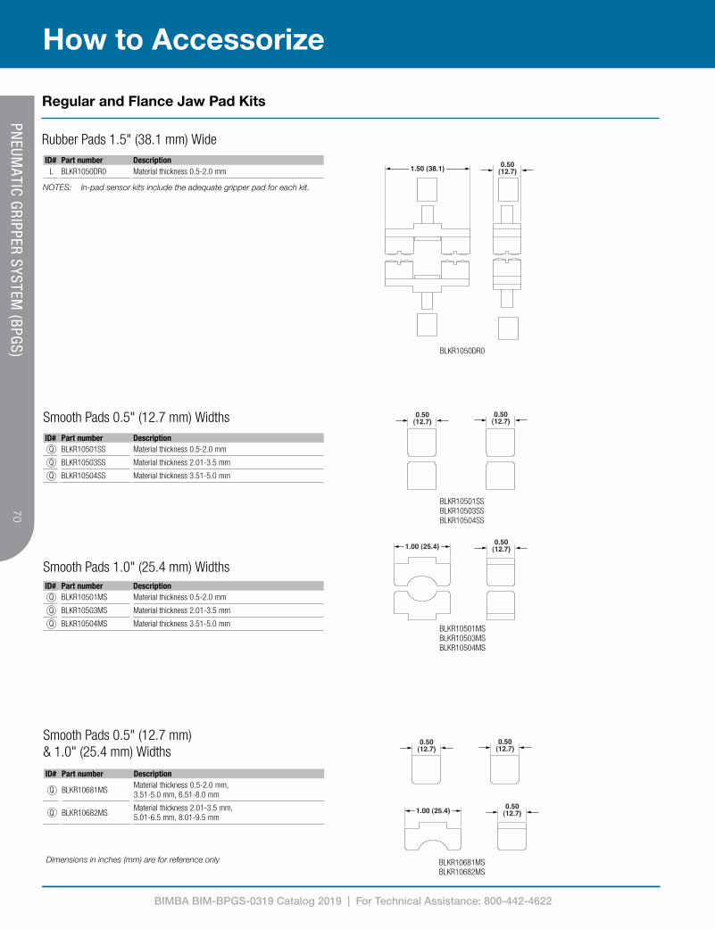
BIMBA BIM-BPGS-0319 Catalog 2019 | For Technical Assistance: 800-442-4622
70
How to Accessorize
70PN
EUMATIC GRIPPER SYSTEM
(BPGS)
ID# Part number DescriptionL BLKR1050DR0 Material thickness 0.5-2.0 mm
ID# Part number DescriptionQ BLKR10501SS Material thickness 0.5-2.0 mm
Q BLKR10503SS Material thickness 2.01-3.5 mm
Q BLKR10504SS Material thickness 3.51-5.0 mm
ID# Part number DescriptionQ BLKR10501MS Material thickness 0.5-2.0 mm
Q BLKR10503MS Material thickness 2.01-3.5 mm
Q BLKR10504MS Material thickness 3.51-5.0 mm
Smooth Pads 0.5" (12.7 mm) Widths
ID# Part number Description
Q BLKR10681MSMaterial thickness 0.5-2.0 mm, 3.51-5.0 mm, 6.51-8.0 mm
Q BLKR10682MSMaterial thickness 2.01-3.5 mm, 5.01-6.5 mm, 8.01-9.5 mm
Smooth Pads 0.5" (12.7 mm) & 1.0" (25.4 mm) Widths
BLKR1050DR0
BLKR10501SSBLKR10503SSBLKR10504SS
BLKR10501MSBLKR10503MSBLKR10504MS
Smooth Pads 1.0" (25.4 mm) Widths
Rubber Pads 1.5" (38.1 mm) Wide
1.50 (38.1) 0.50(12.7)
0.50(12.7)
0.50(12.7)
1.00 (25.4)
1.50 (38.1)
1.00 (25.4)
1.50 (38.1)
0.50(12.7)
0.50(12.7)
0.50(12.7)
0.50(12.7)
1.00 (25.4) 0.50(12.7)
0.50(12.7)
0.50(12.7)
0.50(12.7)
0.50(12.7)
0.50(12.7)
0.50(12.7)
1.00 (25.4)
1.00 (25.4)
1.50 (38.1) 0.50(12.7)
0.50(12.7)
0.50(12.7)
1.00 (25.4)
1.50 (38.1)
1.00 (25.4)
1.50 (38.1)
0.50(12.7)
0.50(12.7)
0.50(12.7)
0.50(12.7)
1.00 (25.4) 0.50(12.7)
0.50(12.7)
0.50(12.7)
0.50(12.7)
0.50(12.7)
0.50(12.7)
0.50(12.7)
1.00 (25.4)
1.00 (25.4)
1.50 (38.1) 0.50(12.7)
0.50(12.7)
0.50(12.7)
1.00 (25.4)
1.50 (38.1)
1.00 (25.4)
1.50 (38.1)
0.50(12.7)
0.50(12.7)
0.50(12.7)
0.50(12.7)
1.00 (25.4) 0.50(12.7)
0.50(12.7)
0.50(12.7)
0.50(12.7)
0.50(12.7)
0.50(12.7)
0.50(12.7)
1.00 (25.4)
1.00 (25.4)
1.50 (38.1) 0.50(12.7)
0.50(12.7)
0.50(12.7)
1.00 (25.4)
1.50 (38.1)
1.00 (25.4)
1.50 (38.1)
0.50(12.7)
0.50(12.7)
0.50(12.7)
0.50(12.7)
1.00 (25.4) 0.50(12.7)
0.50(12.7)
0.50(12.7)
0.50(12.7)
0.50(12.7)
0.50(12.7)
0.50(12.7)
1.00 (25.4)
1.00 (25.4)
1.50 (38.1) 0.50(12.7)
0.50(12.7)
0.50(12.7)
1.00 (25.4)
1.50 (38.1)
1.00 (25.4)
1.50 (38.1)
0.50(12.7)
0.50(12.7)
0.50(12.7)
0.50(12.7)
1.00 (25.4) 0.50(12.7)
0.50(12.7)
0.50(12.7)
0.50(12.7)
0.50(12.7)
0.50(12.7)
0.50(12.7)
1.00 (25.4)
1.00 (25.4)
BLKR10681MSBLKR10682MS
NOTES: In-pad sensor kits include the adequate gripper pad for each kit.
Regular and Flance Jaw Pad Kits
Dimensions in inches (mm) are for reference only
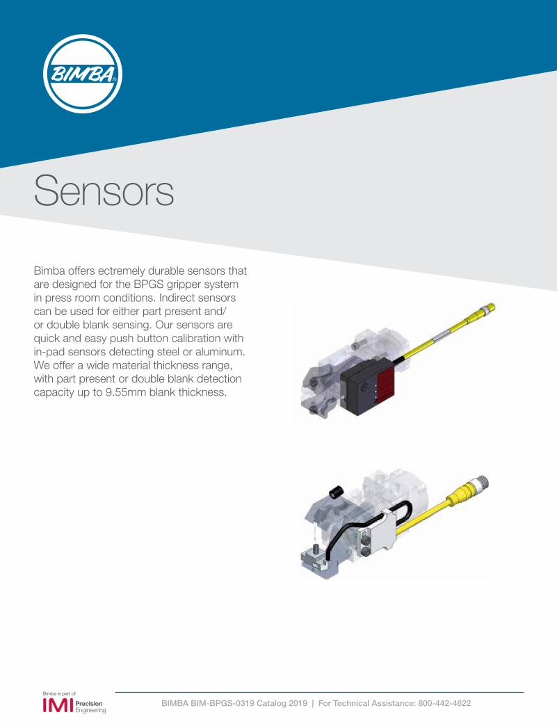
BIMBA BIM-BPGS-0319 Catalog 2019 | For Technical Assistance: 800-442-4622
Sensors
Bimba offers ectremely durable sensors that are designed for the BPGS gripper system in press room conditions. Indirect sensors can be used for either part present and/or double blank sensing. Our sensors are quick and easy push button calibration with in-pad sensors detecting steel or aluminum. We offer a wide material thickness range, with part present or double blank detection capacity up to 9.55mm blank thickness.
(Included w/sensor)
Allen nut.(Included w/sensor)
0.06 (1.5) thick
1.00 (25.4)
Opposing padNote 1
1.21 (30.6)
0.47 (11.9)
3-pinmale pico
9.5 (241-254)
+0.5-0.01.75 (44.5)
1.97 (50.0)
Shim req’d for certain applications

BIMBA BIM-BPGS-0319 Catalog 2019 | For Technical Assistance: 800-442-4622
72
How to Accessorize
72PN
EUMATIC GRIPPER SYSTEM
(BPGS)
Shim req’d for certain applications(Included w/sensor)
Allen nut.(Included w/sensor)
0.06 (1.5) thick
1.00 (25.4)
Opposing padNote 1
1.21 (30.6)
0.47 (11.9)
4.5 (114-127)
+0.5-0.01.75 (44.5)
1.97 (50.0)
4-pin 1-keymale micro
1.21 (30.7)
Allen nut(Included w/sensor)
1.00 (25.4)
Opposing padNote 1
0.47 (11.9) 1.61 (40.9)
4.50 (114-127)
+0.5-0.01.70 (43.2)
4-Pin 1-KeyMale M12
1.21 (30.6)
Shim req’d for certain applications.(Included w/sensor)
Allen nut.(Included w/sensor)
1.00 (24.4)
Opposing padNote 1
0.06 (1.5) thick
0.47 (11.9)
3-pin 2-keymale micro
4.5 (114-127)
+0.5-0.01.75 (44.5)
1.97 (50.0)
(Included w/sensor)
Allen nut.(Included w/sensor)
0.06 (1.5) thick
1.00 (25.4)
Opposing padNote 1
1.21 (30.6)
0.47 (11.9)
3-pinmale pico
9.5 (241-254)
+0.5-0.01.75 (44.5)
1.97 (50.0)
Shim req’d for certain applications (Included w/sensor)
Allen nut.(Included w/sensor)
0.06 (1.5) thick
1.00 (25.4)
Opposing padNote 1
1.21 (30.6)
0.47 (11.9)
3-pinmale pico
9.5 (241-254)
+0.5-0.01.75 (44.5)
1.97 (50.0)
Shim req’d for certain applications
(Included w/sensor)
Allen nut.(Inculded w/sensor)
0.06 (1.5) thick
1.00 (25.4)
Opposing padNote 1
Shim req’d for certain applications
1.21 (30.6)
0.58 (14.7)
9.5 (241-254)
+0.5-0.01.75 (44.5)
1.97 (50.0)
3-pinmale pico
BSGS40040, BSGS40041, BSGS40042, BSGS40043M12 Pin/1 Key NPN/PNP Output
BSGS40040FP, BSGS40041P4, BSGS40042P, BSGS40043P, BSGS40042FP, BSGS40043FP M8 Pin NPN/PNP Output
Page 73 Page 74
BSGS40014 and BSGS40015 0º Standard Pad, NPN/PNP Output M12 4 Pin/1 Key
BSGS40014-30 and BSGS40015-30 30º Standard Pad, NPN/PNP Output M12 Pin/1 Key
BSGS40014-DP and BSGS40015-DP 0º Dual Point Pad,NPN/PNP Output M12 4 Pin/1 Key
BSGS40034 0º Standard Pad, Two Wire Output M12 4 Pin/1 Key
Page 75 Page 76 Page 77 Page 78
BSGS40020 0º Standard Pad, Two Wire Output M12 3 Pin/2 Key 1/2-20
BSGS40020-30 30º Standard Pad, Two Wire Output M12 3 Pin/2 Key 1/2-20
BSGS40021 0º Dual Point Pad,Two wire output M12 3 Pin/2 Key 1/2-20
Page 79 Page 80 Page 81
BSGS40014P and BSGS540015P 0º Standard Pad, NPN/PNP Output M8 3 Pin
BSGS40014P-30 and BSGS40015-30 30º Standard Pad, NPN/PNP Output M8 3 Pin
BSGS40014-DP and BSGS40015-DP 0º Dual Point Pad, NPN/PNP Output M8 3 Pin
BSGS40020P 0º Standard Pad,Two Wire Output M8 3 Pin
Page 82 Page 83 Page 84 Page 85
Quick Find
Indirect Double Blank and Present Sensors
In-pad Part Present Sensor, M12 4 Pin/1 Key
In-pad Part Present Sensor, M12 3 Pin/2 Key 1/2-20
In-pad Part Present Sensor, M8 3 Pin

BIMBA BIM-BPGS-0319 Catalog 2019 | For Technical Assistance: 800-442-4622
73
How to Accessorize73
PNEUM
ATIC GRIPPER SYSTEM (BPGS)
Part number Sensor type Switch typeBSGS40040-K Double blank NPN (Current sinking)BSGS40041-K Double blank PNP (Current sourcing)BSGS40042-K Part present NPN (Current sinking)BSGS40043-K Part present PNP (Current sourcing)BSGS40042F-K Part present flange NPN (Current sinking)BSGS40043F-K Part present flange PNP (Current sourcing)
• Easy calibration• Abrasion and impact resistant• Impervious to contamination from coolants and oils• LED’s for visual feedback• Interface directly to programmable controllers
Power/sensor connector:4-Pin 12 mm (micro type) molded connectorSupply voltage range:10 VDC to 30 VDCMaximum continuous load current:100mA
Operating temperature range:0°C to +60°CResponse time:50ms max.Part present indicator lights: RedDouble blank indicator lights: Red - Blinking
Short circuit protection: YesOverload protection: YesWeight: 0.31 lbs (140 g)
4 Pin, Single KeyMale M12
CalibrationButton
Red LED
6.05 (153.67)
2.31 (58.70)
1.03 (26.16)
1.65 (41.91)
Part Present / Double Blank Sensor with M12 Connector
Technical Data
Ordering Information
Dimensions in inches (mm) are for reference only

BIMBA BIM-BPGS-0319 Catalog 2019 | For Technical Assistance: 800-442-4622
74
How to Accessorize
74PN
EUMATIC GRIPPER SYSTEM
(BPGS)
• Easy calibration• Abrasion and impact resistant• Impervious to contamination from coolants and oil• LED’s for visual feedback• Interface directly to programmable controllers• Compatible with IMI Norgren internal electrics system
Power/sensor connector:4-Pin 8 mm (Pico type) molded connectorSupply voltage range:10 VDC to 30 VDCMaximum continuous load current:100mA
Operating temperature range:0°C to +60°CResponse time:50ms max.Part present indicator lights:RedDouble blank indicator lights:Red-Blinking
Short circuit protection:YesOverload protection:Current limits at 325mA typ.Reverse polarity protection:Up to 36 VDC
Weight: 0.31 lbs (140 g)
2.24 (56.92)
CalibrationButton
RedLED
3 PinMale M8
4 PinMale M8
3
4
1
2
13
4
7.30 (185.4)
1.03 (26.16)
2.19 (55.65)
1.65 (41.91)
Part number # of Pins Sensor Type Switch TypeBSGS40040FP4 4 pins Double Blank Flange NPN (Current Sinking)BSGS40041FP4 4 pins Double Blank Flange PNP (Current Sourcing)BSGS40040P4-K 4 pins Double Blank NPN (Current Sinking)BSGS40041P4-K 4 pins Double Blank PNP (Current Sourcing)BSGS40042P-K 3 pins Part Present NPN (Current Sinking)BSGS40043P-K 3 pins Part Present PNP (Current Sourcing)BSGS40042FP-K 3 pins Part Present Flange NPN (Current Sinking)BSGS40043FP-K 3 pins Part Present Flange PNP (Current Sourcing)
Part Present / Double Blank Sensor with M8 Connector
Ordering Information
Technical Data
Dimensions in inches (mm) are for reference only

BIMBA BIM-BPGS-0319 Catalog 2019 | For Technical Assistance: 800-442-4622
75
How to Accessorize75
PNEUM
ATIC GRIPPER SYSTEM (BPGS)
Shim req’d for certain applications(Included w/sensor)
Allen nut.(Included w/sensor)
0.06 (1.5) thick
1.00 (25.4)
Opposing padNote 1
1.21 (30.6)
0.47 (11.9)
4.5 (114-127)
+0.5-0.01.75 (44.5)
1.97 (50.0)
4-pin 1-keymale micro
• Abrasion and impact resistant• Eliminates sensor position adjustments• LED for part present status of sensor• Interface directly to PLC• Impervious to coolants and oils
Supply voltage range:10 VDC (min) to 30 VDC (max)Maximum continuous loadcurrent:200 mAOperating temperature range:0°C (min) to 60°C (max)Sensing range:1.2 mm above gripper pad
Response time:25ms turn-on time, 60msturn-off timeTarget material:Steel and aluminumIndicator light:RED: On when target is detected;360° visibility
Short circuit protection:Automatically resets when short isremovedOverload protection:Current limits at 325 mA typ.Reverse polarity protection:Up to 36 volts DC
Weight: 0.15 lbs (68 g)
Note 1 - The standard sensor part number (without a KS or KG suffix) can be used with a chisel jaw or flange jaw gripper, or with a regular jaw gripper already fitted with an in-pad sensor. For new installation of an in-pad sensor on a regular jaw gripper, select the part numbers with a KS or KG suffix to include the opposing pad in your kit.
Note 2 - Sensor must be ordered based on thickness of the material being handled. Pad thickness changes to ensure full jaw movement and cam lock action of gripper actuator.
Part number (note 1) Description Sensor type Material thickness (note 2)
BSGS40014 Sensor NPN VariousBSGS40014KS Sensor with opposing pad (Kit) NPN 0.50-3.50 mmBSGS40014KG Sensor with opposing pad (Kit) NPN 2.01-5.00 mmBSGS40015 Sensor PNP VariousBSGS40015KS Sensor with opposing pad (Kit) PNP 0.50-3.50 mmBSGS40015KG Sensor with opposing pad (Kit) PNP 2.01-5.00 mm
Spare partsB07750 - allen nutB07769 - shim
1.61 (40.9 )
1.70 (43.2)
0.47 (11.9)
4.5 +0.5 / -0.0 (114-127)
4-Pin 1-KeyMale M12
1.21 (30.6)
SGS40015
SHOWN
WEIGHT: .15 lbs. [68 grams]
4.50 (114-127)
+0.5-0.0
Shim required for certain applications (included with sensor)
Allen nut (included with sensor)
0.06 (1.5) thick
1.00 (25.4)
Opposing padNote 1
1.21 (30.6)
0.47 (11.9)
4.5 (114-127)
+0.5-0.01.75 (44.5)
1.97 (50.0)
4-Pin 1-KeyMale MICRO
In-Pad Part Present Sensor, M12 4 PIN/1 Key 0° Standard Pad, NPN/PNP Outlet
Technical Data
Ordering Information
Dimensions in inches (mm) are for reference only

BIMBA BIM-BPGS-0319 Catalog 2019 | For Technical Assistance: 800-442-4622
76
How to Accessorize
76PN
EUMATIC GRIPPER SYSTEM
(BPGS)
• Abrasion and impact resistant• Eliminates sensor position adjustments• Interface directly to PLC• Impervious to coolants and oils
Supply voltage range:10 VDC (min) to 30 VDC (max)Maximum continuous load current: 200 mAOperating temperature range:0°C (min) to 60°C (max)
Sensing range:1.2 mm above gripper padResponse time:25 ms turn-on time, 60 ms turn-off timeTarget material:Steel and aluminum
Short circuit protection:Automatically resets when short is removedOverload protection:Current limits at 325 mA typ.Reverse polarity protection:Up to 36 volts DC
Weight: 0.15 lbs (68 g)
Note 1 - The standard sensor part number (without a KS or KG suffix) can be used with a chisel jaw or flange jaw gripper, or with a regular jaw gripper already fitted with an in-pad sensor. For new installation of an in-pad sensor on a regular jaw gripper, select the part numbers with a KS or KG suffix to include the opposing pad in your kit.
Note 2 - Sensor must be ordered based on thickness of the material being handled. Pad thickness changes to ensure full jaw movement and cam lock action of gripper actuator.
Part number (note 1) Description NPN/PNP Material thickness (note 2)
BSGS40014-30 Sensor NPN VariousBSGS40014KS-30 Sensor with opposing pad (Kit) NPN 0.50-3.50 mmBSGS40014KG-30 Sensor with opposing pad (Kit) NPN 2.01-5.00 mmBSGS40015-30 Sensor PNP VariousBSGS40015KS-30 Sensor with opposing pad (Kit) PNP 0.50-3.50 mmBSGS40015KG-30 Sensor with opposing pad (Kit) PNP 2.01-5.00 mm
Spare partsB07750 - allen nutB07769 - shim
4-Pin One KeyMale M12
1.70 (43.2)
0.58 (14.7)
1.61 (40.9)
1.21 (30.6)
SGS40015-30
SHOWN
WEIGHT: .15 lbs. [68 grams]
4.5 +0.5 / -0.0 (114 - 127)
+0.5 -0.0
4.50 (114-127)
+0.5-0.0
Shim required for certain applications (included with sensor)
0.06 (1.5) thick
Allen nut (included with sensor)
Opposing padnote 1
1.00 (25.4)
1.21 (30.6)
0.58 (14.7)
1.75 (44.5) 9.5 (241-254)
+0.5-0.0
4-Pin, Single KeyMale MICRO
1.97 (50.0)
In-Pad Part Present Sensor, M12 4 Pin/1 Key 30° Standard Pad, NPN/PNP Outlet
Technical Data
Ordering Information
Dimensions in inches (mm) are for reference only
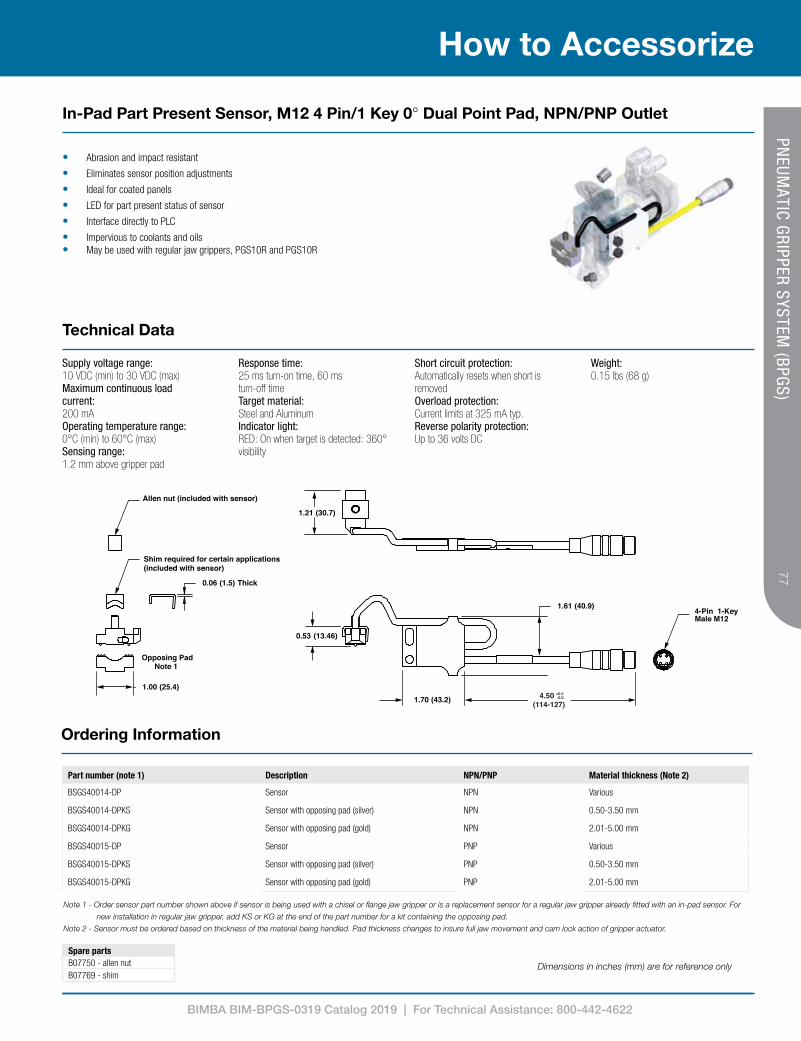
BIMBA BIM-BPGS-0319 Catalog 2019 | For Technical Assistance: 800-442-4622
77
How to Accessorize77
PNEUM
ATIC GRIPPER SYSTEM (BPGS)
• Abrasion and impact resistant
• Eliminates sensor position adjustments
• Ideal for coated panels
• LED for part present status of sensor
• Interface directly to PLC
• Impervious to coolants and oils• May be used with regular jaw grippers, PGS10R and PGS10R
Note 1 - Order sensor part number shown above if sensor is being used with a chisel or flange jaw gripper or is a replacement sensor for a regular jaw gripper already fitted with an in-pad sensor. For
new installation in regular jaw gripper, add KS or KG at the end of the part number for a kit containing the opposing pad.
Note 2 - Sensor must be ordered based on thickness of the material being handled. Pad thickness changes to insure full jaw movement and cam lock action of gripper actuator.
Part number (note 1) Description NPN/PNP Material thickness (Note 2)
BSGS40014-DP Sensor NPN Various
BSGS40014-DPKS Sensor with opposing pad (silver) NPN 0.50-3.50 mm
BSGS40014-DPKG Sensor with opposing pad (gold) NPN 2.01-5.00 mm
BSGS40015-DP Sensor PNP Various
BSGS40015-DPKS Sensor with opposing pad (silver) PNP 0.50-3.50 mm
BSGS40015-DPKG Sensor with opposing pad (gold) PNP 2.01-5.00 mm
1.61 (40.9)
1.70 (43.2)
0.53 (13.46)
1.00 (25.4)
Opposing PadNote 1
Allen nut (included with sensor)
Shim required for certain applications (included with sensor)
0.06 Thick(1.5)
4-Pin 1-KeyMale M12
1.21 (30.7)
4.50 (114-127)
+0.5-0.0
Supply voltage range:10 VDC (min) to 30 VDC (max)Maximum continuous load current: 200 mAOperating temperature range:0°C (min) to 60°C (max)Sensing range:1.2 mm above gripper pad
Response time:25 ms turn-on time, 60 ms turn-off timeTarget material:Steel and AluminumIndicator light:RED: On when target is detected: 360° visibility
Short circuit protection:Automatically resets when short is removedOverload protection:Current limits at 325 mA typ.Reverse polarity protection:Up to 36 volts DC
Weight: 0.15 lbs (68 g)
Spare partsB07750 - allen nutB07769 - shim
In-Pad Part Present Sensor, M12 4 Pin/1 Key 0° Dual Point Pad, NPN/PNP Outlet
Technical Data
Ordering Information
Dimensions in inches (mm) are for reference only

BIMBA BIM-BPGS-0319 Catalog 2019 | For Technical Assistance: 800-442-4622
78
How to Accessorize
78PN
EUMATIC GRIPPER SYSTEM
(BPGS)
1.21 (30.7)
Allen nut(Included w/sensor)
1.00 (25.4)
Opposing padNote 1
0.47 (11.9) 1.61 (40.9)
4.50 (114-127)
+0.5-0.01.70 (43.2)
4-Pin 1-KeyMale M12
1.21 (30.7)
Allen nut(Included w/sensor)
1.00 (25.4)
Opposing padNote 1
0.47 (11.9) 1.61 (40.9)
4.50 (114-127)
+0.5-0.01.70 (43.2)
4-Pin 1-KeyMale M12
• Abrasion and impact resistant• Eliminates sensor position adjustments• Interface directly to PLC• Impervious to coolants and oils
Part number (note 1) Description Material thickness (note 2)
BSGS40034 Sensor Various
BSGS40034KC Sensor with opposing pad (copper) 0.40 - 2.00 mm
BSGS40034KS Sensor with opposing pad (silver) 2.01 - 3.50 mm
BSGS40034KG Sensor with opposing pad (gold) 3.51 - 5.00 mm
BSGS40034KO Sensor with opposing pad (olive) 5.01 - 6.50 mm
Spare partsB07750 - allen nutB07769 - shim
Note 1 - The standard sensor part number (without a KS or KG suffix) can be used with a chisel jaw or flange jaw gripper, or with a regular jaw gripper already fitted with an in-pad sensor. For new
installation of an in-pad sensor on a regular jaw gripper, select the part numbers with a KS or KG suffix to include the opposing pad in your kit.
Note 2 - Sensor must be ordered based on thickness of the material being handled. Pad thickness changes to ensure full jaw movement and cam lock action of gripper actuator.
Power/sensor connector:3-pin 8 mm (pico type) male connectorSupply voltage range:24 VDCMaximum off-state leakage current:1.3mA @ 24 VDCMaximum continuous load current:40mAOperating temperature range:0ºC (min) to 60ºC (max)
Sensing range:1.2 mm above gripper padResponse time:25ms turn-on time, 60ms turn-off timeTarget material:Steel and aluminum
Indicator light:RED: On when target is detected; 360º visibilityShort circuit protection:Yes: Automatically resets when short is removedOverload protection:Yes
On-state voltage drop:8.5 VWeight: 0.15 lbs (68 g)
Shim required for certain applications (included with sensor)
Allen nut (included with sensor)
0.06 (1.5) thick
1.00 (25.4)
Opposing padNote 1
1.21 (30.6)
0.47 (11.9)
4.5 (114-127)
+0.5-0.01.75 (44.5)
1.97 (50.0)
4-Pin 1-KeyMale MICRO
In-Pad Part Present Sensor, M12 4 Pin/1 Key 0° Standard Pad, Two Wire Output
Technical Data
Ordering Information
Dimensions in inches (mm) are for reference only

BIMBA BIM-BPGS-0319 Catalog 2019 | For Technical Assistance: 800-442-4622
79
How to Accessorize79
PNEUM
ATIC GRIPPER SYSTEM (BPGS)
• Abrasion and impact resistant• Eliminates sensor position adjustments• Interface directly to PLC• Impervious to coolants and oils
Part number (note 1) Description Material thickness (note 2)
BSGS40020 Sensor Various
BSGS40020KS Sensor with opposing pad 0.50-3.50 mm
BSGS40020KG Sensor with opposing pad 2.01-5.00 mm
Spare partsB07750 - allen nutB07769 - shim
Note 1 - The standard sensor part number (without a KS or KG suffix) can be used with a chisel jaw or flange jaw gripper, or with a regular jaw gripper already fitted with an
in-pad sensor. For new installation of an in-pad sensor on a regular jaw gripper, select the part numbers with a KS or KG suffix to include the opposing pad in your kit.
Note 2 - Sensor must be ordered based on thickness of the material being handled. Pad thickness changes to ensure full jaw movement and cam lock action of gripper actuator.
Power/sensor connector:3-pin 1/2-20unf (micro type), two key male connectorSupply voltage range:24 V AC/DC to 140 V AC/DCMaximum off-state leakage current:1.3mA @ 120VMaximum continuous load current:40mAOperating temperature range:0ºC (min) to 60ºC (max)
Sensing range:1.2mm above gripper padResponse time:25ms turn-on time, 25ms turn-off time.Target material:Steel and aluminum
Indicator light:RED: On when target is detected; 360º visibilityShort circuit protection:Yes: Automatically resets when short is removedOverload protection:Yes
On-state voltage drop:8.5 VWeight: 0.15 lbs (68 g)
1.21 (30.7)
Allen nut(Included w/sensor)
1.00 (25.4)
Opposing padNote 1
0.47 (11.9) 1.61 (40.9)
4.50 (114-127)
+0.5-0.01.70 (43.2)
4-Pin 1-KeyMale M12
0.47 (11.9)
1.61 (40.9)
1.70 (43.2)
3-Pin 2-KeyMale M12
1.21 (30.6)
SGS40020
SHOWN
WEIGHT: .15 lbs. [68 grams]
4.50 (114-127)
+0.5-0.0
1.21 (30.6)
Shim required for certain applications (included with sensor)
Allen nut (included with sensor)
1.00 (24.4)
Opposing padNote 1
0.06 (1.5) thick
0.47 (11.9)
3-Pin 2-KeyMale MICRO
4.5 (114-127)
+0.5-0.01.75 (44.5)
1.97 (50.0)
In-Pad Part Present Sensor, M12 3 Pin/2 Key 1/2-20 0° Standard Pad, Two Wire Output
Technical Data
Ordering Information
Dimensions in inches (mm) are for reference only
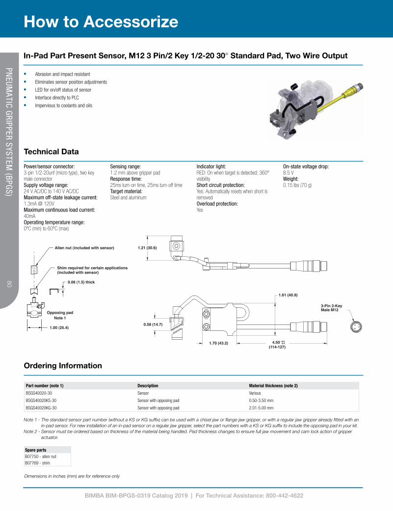
BIMBA BIM-BPGS-0319 Catalog 2019 | For Technical Assistance: 800-442-4622
80
How to Accessorize
80PN
EUMATIC GRIPPER SYSTEM
(BPGS)
• Abrasion and impact resistant
• Eliminates sensor position adjustments
• LED for on/off status of sensor
• Interface directly to PLC
• Impervious to coolants and oils
Part number (note 1) Description Material thickness (note 2)
BSGS40020-30 Sensor Various
BSGS40020KS-30 Sensor with opposing pad 0.50-3.50 mm
BSGS40020KG-30 Sensor with opposing pad 2.01-5.00 mm
Spare partsB07750 - allen nutB07769 - shim
Note 1 - The standard sensor part number (without a KS or KG suffix) can be used with a chisel jaw or flange jaw gripper, or with a regular jaw gripper already fitted with an in-pad sensor. For new installation of an in-pad sensor on a regular jaw gripper, select the part numbers with a KS or KG suffix to include the opposing pad in your kit.
Note 2 - Sensor must be ordered based on thickness of the material being handled. Pad thickness changes to ensure full jaw movement and cam lock action of gripper actuator.
Power/sensor connector:3-pin 1/2-20unf (micro type), two key male connectorSupply voltage range:24 V AC/DC to 140 V AC/DCMaximum off-state leakage current:1.3mA @ 120VMaximum continuous load current:40mAOperating temperature range:0ºC (min) to 60ºC (max)
Sensing range:1.2 mm above gripper padResponse time:25ms turn-on time, 25ms turn-off timeTarget material:Steel and aluminum
Indicator light:RED: On when target is detected; 360º visibilityShort circuit protection:Yes: Automatically resets when short is removedOverload protection:Yes
On-state voltage drop:8.5 VWeight: 0.15 lbs (70 g)
0.58 (14.7)
1.70 (43.2)
1.61 (40.9)
1.21 (30.6)
3-Pin 2-KeyMale M12
SGS40020-30
SHOWN
WEIGHT: .15 lbs. [68 grams]
4.50 (114-127)
+0.5-0.0
Shim required for certain applications (included with sensor)
Allen nut (included with sensor)
0.06 (1.5) thick
1.00 (25.4)
Opposing padNote 1
1.21 (30.6)
0.58 (14.7)
1.97 (50.0)3-Pin 2-KeyMale MICRO
4.5 (114-127)
+0.5-0.01.75 (44.5)
In-Pad Part Present Sensor, M12 3 Pin/2 Key 1/2-20 30° Standard Pad, Two Wire Output
Technical Data
Ordering Information
Dimensions in inches (mm) are for reference only

BIMBA BIM-BPGS-0319 Catalog 2019 | For Technical Assistance: 800-442-4622
81
How to Accessorize81
PNEUM
ATIC GRIPPER SYSTEM (BPGS)
• Abrasion and impact resistant• Eliminates sensor position adjustments• For use with coated panels• LED for on/off status of sensor• Interface directly to PLC• Impervious to coolants and oils• May be used with regular jaw grippers, PGS10R and PGS10R
Part number (note 1) Description Material thickness (note 2)
BSGS40021 Sensor Various
BSGS40021KS Sensor with opposing pad (Kit) 0.50-3.50 mm
BSGS40021KG Sensor with opposing pad (Kit) 2.01-5.00 mm
Spare partsB07750 - allen nutB07769 - shim
Note 1 - The standard sensor part number (without a KS or KG suffix) can be used with a chisel jaw or flange jaw gripper, or with a regular jaw gripper already fitted with an in-pad sensor. For new installation of an in-pad sensor on a regular jaw gripper, select the part numbers with a KS or KG suffix to include the opposing pad in your kit.
Note 2 - Sensor must be ordered based on thickness of the material being handled. Pad thickness changes to ensure full jaw movement and cam lock action of gripper actuator.
Power/sensor connector:3-pin 1/2-20unf (micro type), two key male connectorSupply voltage range:24 V AC/DC to 140 V AC/DCMaximum off-state leakage current:1.3mA @ 120 VMaximum continuous load current:40mAOperating temperature range:0ºC (min) to 60ºC (max)
Sensing range:1.2 mm above gripper padResponse time:25ms turn-on time, 25ms turn-off time.Target material:Steel and aluminum
Indicator light:RED: On when target is detected; 360º visibilityShort circuit protection:Yes: Automatically resets when short is removedOverload protection:Yes
On-state voltage drop:8.5 VWeight: 0.15 lbs (70 g)
0.47 (11.9)
1.61 (40.9)
1.70 (43.2)
3-Pin 2-KeyMale M12
1.21 (30.6)
SGS40020
SHOWN
WEIGHT: .15 lbs. [68 grams]
4.50 (114-127)
+0.5-0.0
Shim required for certain applications (included with sensor)
Allen nut (included with sensor)
0.06 (1.5) thick
1.21 (30.6)
1.00 (25.4)
Opposing padNote 1
0.47 (11.9)
4.5 (114-127)
+0.5-0.01.75 (44.5)
3-Pin 2-KeyMale MICRO1.97 (50.0)
In-Pad Part Present Sensor, M12 3 Pin/2 Key 1/2-20 0° Dual Point Pad, Two Wire Output
Technical Data
Ordering Information
Dimensions in inches (mm) are for reference only

BIMBA BIM-BPGS-0319 Catalog 2019 | For Technical Assistance: 800-442-4622
82
How to Accessorize
82PN
EUMATIC GRIPPER SYSTEM
(BPGS)
(Included w/sensor)
Allen nut.(Included w/sensor)
0.06 (1.5) thick
1.00 (25.4)
Opposing padNote 1
1.21 (30.6)
0.47 (11.9)
3-pinmale pico
9.5 (241-254)
+0.5-0.01.75 (44.5)
1.97 (50.0)
Shim req’d for certain applications
• Abrasion and impact resistant• Eliminates sensor position adjustments• Interface directly to PLC• Impervious to coolants and oils
Supply voltage range:10 VDC (min) to 30 VDC (max)Maximum continuous loadcurrent:200 mAOperating temperature range: 0°C (min) to 60°C (max)
Sensing range:1.2 mm above gripper padResponse time:25 ms turn-on time, 60 msturn-off timeTarget material:Steel and aluminum
Short circuit protection:Automatically resets when short isremovedOverload protection:Current limits at 325 mA typ.Reverse polarity protection:Up to 36 volts DC
Weight: 0.15 lbs (68 g)
Note 1 - The standard sensor part number (without a KS or KG suffix) can be used with a chisel jaw or flange jaw gripper, or with a regular jaw gripper already fitted with an in-pad sensor. For new
installation of an in-pad sensor on a regular jaw gripper, select the part numbers with a KS or KG suffix to include the opposing pad in your kit.
Note 2 - Sensor must be ordered based on thickness of the material being handled. Pad thickness changes to ensure full jaw movement and cam lock action of gripper actuator.
Part number (note 1) Description NPN/PNP Material thickness (note 2)
BSGS40014P Sensor NPN VariousBSGS40014PKS Sensor with opposing pad (Kit) NPN 0.50-3.50 mmBSGS40014PKG Sensor with opposing pad (Kit) NPN 2.01-5.00 mmBSGS40015P Sensor PNP VariousBSGS40015PKS Sensor with opposing pad (Kit) PNP 0.50-3.50 mmBSGS40015PKG Sensor with opposing pad (Kit) PNP 2.01-5.00 mm
Spare partsB07750 - allen nutB07769 - shim
0.47 (11.9)
1.70 (43.2)
9.5 " +0.5 / -0.0 (241-254 mm)
1.61 (40.9)
1.21 (30.6)
3-PinMaleM8
SGS40014P
SHOWN
WEIGHT: .15 lbs. [68 grams]
9.50 (241-254)
+0.5-0.0
Allen nut (included with sensor)
0.06 (1.5) thick
1.00 (25.4)
Opposing padNote 1
1.21 (30.6)
0.47 (11.9)
3-pinmale pico
9.5 (241-254)
+0.5-0.01.75 (44.5)
1.97 (50.0)
Shim required for certain applications (included with sensor)
In-Pad Part Present Sensor, M8 3 Pin 0° Standard Pad, NPN/PNP Output
Technical Data
Ordering Information
Dimensions in inches (mm) are for reference only
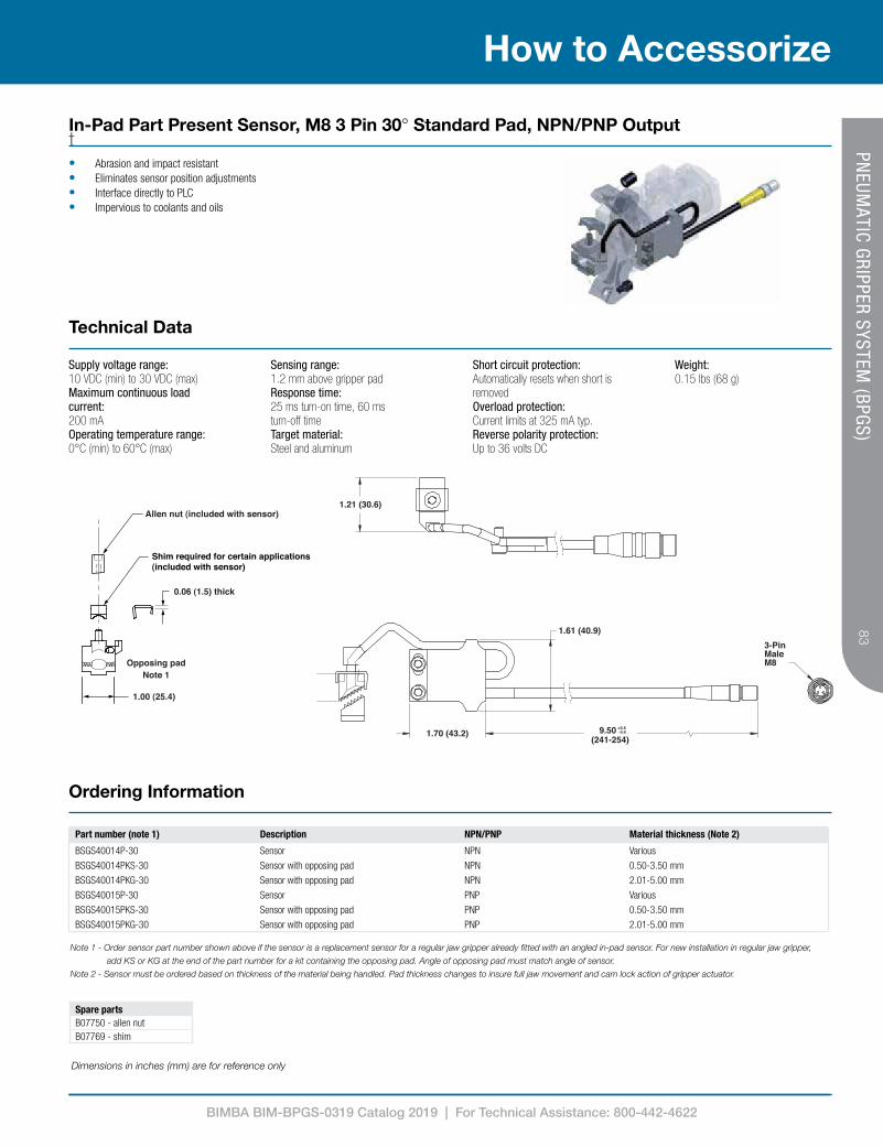
BIMBA BIM-BPGS-0319 Catalog 2019 | For Technical Assistance: 800-442-4622
83
How to Accessorize83
PNEUM
ATIC GRIPPER SYSTEM (BPGS)
(Included w/sensor)
Allen nut.(Inculded w/sensor)
0.06 (1.5) thick
1.00 (25.4)
Opposing padNote 1
Shim req’d for certain applications
1.21 (30.6)
0.58 (14.7)
9.5 (241-254)
+0.5-0.01.75 (44.5)
1.97 (50.0)
3-pinmale pico
t • Abrasion and impact resistant• Eliminates sensor position adjustments• Interface directly to PLC• Impervious to coolants and oils
Supply voltage range:10 VDC (min) to 30 VDC (max)Maximum continuous loadcurrent:200 mAOperating temperature range:0°C (min) to 60°C (max)
Sensing range:1.2 mm above gripper padResponse time:25 ms turn-on time, 60 msturn-off timeTarget material:Steel and aluminum
Short circuit protection:Automatically resets when short isremovedOverload protection:Current limits at 325 mA typ.Reverse polarity protection:Up to 36 volts DC
Weight: 0.15 lbs (68 g)
Note 1 - Order sensor part number shown above if the sensor is a replacement sensor for a regular jaw gripper already fitted with an angled in-pad sensor. For new installation in regular jaw gripper,
add KS or KG at the end of the part number for a kit containing the opposing pad. Angle of opposing pad must match angle of sensor.
Note 2 - Sensor must be ordered based on thickness of the material being handled. Pad thickness changes to insure full jaw movement and cam lock action of gripper actuator.
Part number (note 1) Description NPN/PNP Material thickness (Note 2)
BSGS40014P-30 Sensor NPN VariousBSGS40014PKS-30 Sensor with opposing pad NPN 0.50-3.50 mmBSGS40014PKG-30 Sensor with opposing pad NPN 2.01-5.00 mmBSGS40015P-30 Sensor PNP VariousBSGS40015PKS-30 Sensor with opposing pad PNP 0.50-3.50 mmBSGS40015PKG-30 Sensor with opposing pad PNP 2.01-5.00 mm
Spare partsB07750 - allen nutB07769 - shim
1.70 (43.2)
9.50" +0.5 / -0.0 (241-254 mm)
1.61 (40.9)
0.58 (14.7)
1.21 (30.6)
3-PinMaleM8
SGS40014P-30
SHOWN
WEIGHT: .15 lbs. [68 grams]
9.50 (241-254)
+0.5-0.0
Allen nut (included with sensor)
0.06 (1.5) thick
1.00 (25.4)
Opposing padNote 1
Shim required for certain applications (included with sensor)
1.21 (30.6)
0.58 (14.7)
9.5 (241-254)
+0.5-0.01.75 (44.5)
1.97 (50.0)
3-pinmale pico
In-Pad Part Present Sensor, M8 3 Pin 30° Standard Pad, NPN/PNP Output
Technical Data
Ordering Information
Dimensions in inches (mm) are for reference only

BIMBA BIM-BPGS-0319 Catalog 2019 | For Technical Assistance: 800-442-4622
84
How to Accessorize
84PN
EUMATIC GRIPPER SYSTEM
(BPGS)
Note 1 - Order sensor part number shown above if sensor is being used with a chisel or flange jaw gripper or is a replacement sensor for a regular jaw gripper already fitted with an in-pad sensor. For
new installation in regular jaw gripper, add KS or KG at the end of the part number for a kit containing the opposing pad.
Note 2 - Sensor must be ordered based on thickness of the material being handled. Pad thickness changes to insure full jaw movement and cam lock action of gripper actuator.
Part number (note 1) Description NPN/PNP Material thickness (Note 2)
BSGS40014-DP Sensor NPN Various
BSGS40014-DPKS Sensor with opposing pad (silver) NPN 0.50-3.50 mm
BSGS40014-DPKG Sensor with opposing pad (gold) NPN 2.01-5.00 mm
BSGS40015-DP Sensor PNP Various
BSGS40015-DPKS Sensor with opposing pad (silver) PNP 0.50-3.50 mm
BSGS40015-DPKG Sensor with opposing pad (gold) PNP 2.01-5.00 mm
1.00 (25.4)
Opposing PadNote 1
Allen nut (included with sensor)
Shim required for certain applications (included with sensor)
0.06 Thick(1.5)
0.53 (13.5)
1.70 (43.2)
3-PinMaleM8
1.61 (40.9)
1.21 (30.7)
9.50 (241-254)
+0.5-0.0
• Abrasion and impact resistant• Eliminates sensor position adjustments• For use with coated panels• LED for on/off status of sensor• Interface directly to PLC• Impervious to coolants and oils• May be used with regular jaw grippers, PGS10R and PGS10R
Supply voltage range:10 VDC (min) to 30 VDC (max)Maximum continuous load current: 200 mAOperating temperature range:0°C (min) to 60°C (max)
Sensing range:1.2 mm above gripper padResponse time:25 ms turn-on time, 60 ms turn-off timeTarget material:Steel and aluminum
Short circuit protection:Automatically resets when short is removedOverload protection:Current limits at 325 mA typ.
Reverse polarity protection:Up to 36 volts DCWeight: 0.15 lbs (68 g)
Spare partsB07750 - allen nutB07769 - shim
In-Pad Part Present Sensor, M8 3 Pin 0° Dual Point Pad, NPN/PNP Output
Technical Data
Ordering Information
Dimensions in inches (mm) are for reference only
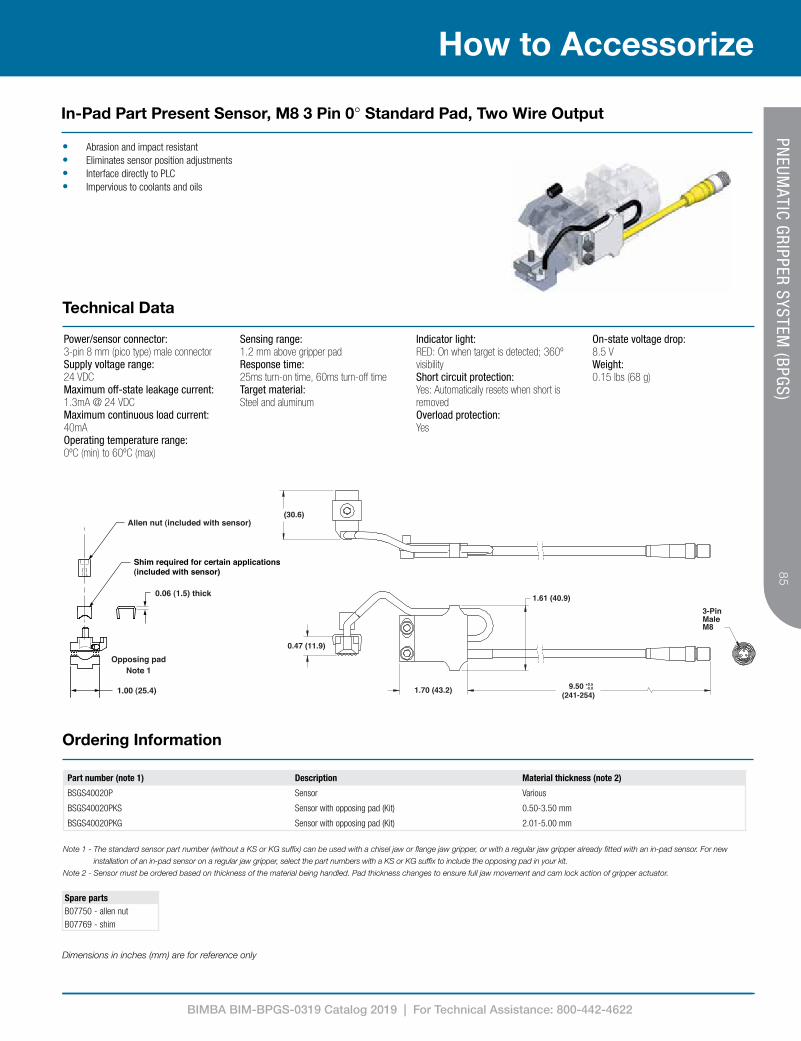
BIMBA BIM-BPGS-0319 Catalog 2019 | For Technical Assistance: 800-442-4622
85
How to Accessorize85
PNEUM
ATIC GRIPPER SYSTEM (BPGS)
• Abrasion and impact resistant• Eliminates sensor position adjustments• Interface directly to PLC• Impervious to coolants and oils
Part number (note 1) Description Material thickness (note 2)
BSGS40020P Sensor Various
BSGS40020PKS Sensor with opposing pad (Kit) 0.50-3.50 mm
BSGS40020PKG Sensor with opposing pad (Kit) 2.01-5.00 mm
Spare partsB07750 - allen nutB07769 - shim
Power/sensor connector:3-pin 8 mm (pico type) male connectorSupply voltage range:24 VDCMaximum off-state leakage current:1.3mA @ 24 VDCMaximum continuous load current:40mAOperating temperature range:0ºC (min) to 60ºC (max)
Sensing range:1.2 mm above gripper padResponse time:25ms turn-on time, 60ms turn-off timeTarget material:Steel and aluminum
Indicator light:RED: On when target is detected; 360º visibilityShort circuit protection:Yes: Automatically resets when short is removedOverload protection:Yes
On-state voltage drop:8.5 VWeight: 0.15 lbs (68 g)
Note 1 - The standard sensor part number (without a KS or KG suffix) can be used with a chisel jaw or flange jaw gripper, or with a regular jaw gripper already fitted with an in-pad sensor. For new
installation of an in-pad sensor on a regular jaw gripper, select the part numbers with a KS or KG suffix to include the opposing pad in your kit.
Note 2 - Sensor must be ordered based on thickness of the material being handled. Pad thickness changes to ensure full jaw movement and cam lock action of gripper actuator.
(Included w/sensor)
Allen nut.(Included w/sensor)
0.06 (1.5) thick
1.00 (25.4)
Opposing padNote 1
1.21 (30.6)
0.47 (11.9)
3-pinmale pico
9.5 (241-254)
+0.5-0.01.75 (44.5)
1.97 (50.0)
Shim req’d for certain applications
0.47 (11.9)
1.70 (43.2)
9.5 " +0.5 / -0.0 (241-254 mm)
1.61 (40.9)
1.21 (30.6)
3-PinMaleM8
SGS40014P
SHOWN
WEIGHT: .15 lbs. [68 grams]
9.50 (241-254)
+0.5-0.0
Allen nut (included with sensor)
0.06 (1.5) thick
1.00 (25.4)
Opposing padNote 1
1.21 (30.6)
0.47 (11.9)
3-pinmale pico
9.5 (241-254)
+0.5-0.01.75 (44.5)
1.97 (50.0)
Shim required for certain applications (included with sensor)
In-Pad Part Present Sensor, M8 3 Pin 0° Standard Pad, Two Wire Output
Technical Data
Ordering Information
Dimensions in inches (mm) are for reference only
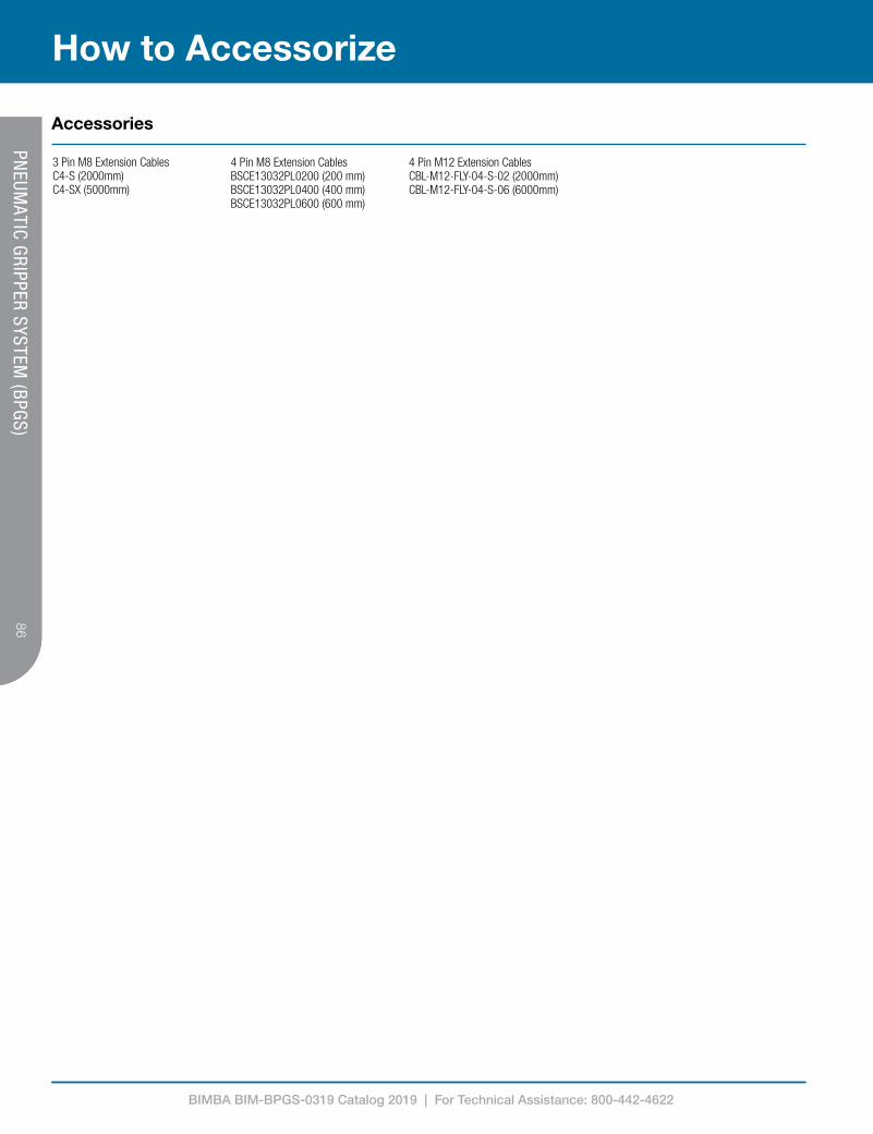
BIMBA BIM-BPGS-0319 Catalog 2019 | For Technical Assistance: 800-442-4622
86
How to Accessorize
86PN
EUMATIC GRIPPER SYSTEM
(BPGS)
3 Pin M8 Extension CablesC4-S (2000mm)C4-SX (5000mm)
4 Pin M8 Extension CablesBSCE13032PL0200 (200 mm)BSCE13032PL0400 (400 mm)BSCE13032PL0600 (600 mm)
4 Pin M12 Extension CablesCBL-M12-FLY-04-S-02 (2000mm)CBL-M12-FLY-04-S-06 (6000mm)
Accessories

BIMBA BIM-BPGS-0319 Catalog 2019 | For Technical Assistance: 800-442-4622
87
Notes87
PNEUM
ATIC GRIPPER SYSTEM (BPGS)

Bimba 25150 S. Governors Hwy University Park, IL 60484
Tel: +1 708 534 8544 Fax: +1 708 235 2014
Due to our policy of continuous development, Bimba reserve the right to change specifications without prior notice.
BIM-CRVTC-0518
Selected Images used under license from Shutterstock.com
IMI Precision Engineering operates four global centres of technical excellence and a sales and service network in 75 countries, as well as manufacturing capability in the USA, Germany, China, UK, Switzerland, Czech Republic, Mexico and Brazil.
For information on all IMI Precision Engineering companies visit www.imi-precision.com
Supported by distributors worldwide.
For further information, scan this QR code or visit www.bimba.com