PMA Prozeß- und Maschinen-Automation GmbH - … · 1 Mounting a Fix the instrument only at top and...
84
PMA Prozeß- und Maschinen-Automation GmbH KS 90-1 programmer and KS 92-1 programmer Operating manual English 9499-040-66111 Valid from: 8499 advanced line KS90-1 KS90-1
-
Upload
nguyendieu -
Category
Documents
-
view
220 -
download
0
Transcript of PMA Prozeß- und Maschinen-Automation GmbH - … · 1 Mounting a Fix the instrument only at top and...
PMA Prozeß- und Maschinen-Automation GmbH
KS 90-1 programmerand KS 92-1 programmer
Operating manual
English
9499-040-66111
Valid from: 8499
advanced line
KS90-1
KS90-1

© PMA Prozeß- und Maschinen-Automation GmbH Printed in Germany
All rights reserved. No part of this document may bereproduced or published in any form or by any means
without prior written permission from the copyright owner.
A publication of PMA Prozeß- und Maschinen Automation
P.O.Box 310229
D-34058 Kassel
Germany
û BlueControl
More efficiency in engineering,more overview in operating:
The projecting environment for the BluePort controllers
ATTENTION!
Mini V
ersion
andUpdate
s on
or onPM
A-CD
www.pm
a-onlin
e.de
Description of symbolsin the text: on the device:
g General information a Follow the operating instructions
a General warning
l Attention: ESD-sensitive devices
KS 90-1p / KS 92-1p 3
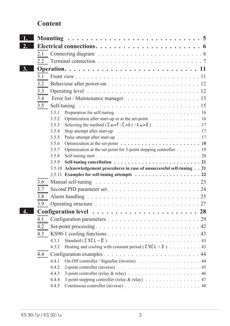
Content
1. Mounting . . . . . . . . . . . . . . . . . . . . . . . . . . . . . 5
2. Electrical connections . . . . . . . . . . . . . . . . . . . . . . . 6
2.1 Connecting diagram . . . . . . . . . . . . . . . . . . . . . . . . . . 6
2.2 Terminal connection . . . . . . . . . . . . . . . . . . . . . . . . . . 7
3. Operation. . . . . . . . . . . . . . . . . . . . . . . . . . . . . 11
3.1 Front view . . . . . . . . . . . . . . . . . . . . . . . . . . . . . . . 11
3.2 Behaviour after power-on . . . . . . . . . . . . . . . . . . . . . . . 12
3.3 Operating level . . . . . . . . . . . . . . . . . . . . . . . . . . . . 12
3.4 Error list / Maintenance manager. . . . . . . . . . . . . . . . . . . 13
3.5 Self-tuning. . . . . . . . . . . . . . . . . . . . . . . . . . . . . . . 15
3.5.1 Preparation for self-tuning . . . . . . . . . . . . . . . . . . . . . . . . . 16
3.5.2 Optimization after start-up or at the set-point . . . . . . . . . . . . . . . 16
3.5.3 Selecting the method ( ConF/ Cntr/ tunE) . . . . . . . . . . . . . . 17
3.5.4 Step attempt after start-up . . . . . . . . . . . . . . . . . . . . . . . . 17
3.5.5 Pulse attempt after start-up . . . . . . . . . . . . . . . . . . . . . . . . 17
3.5.6 Optimization at the set-point . . . . . . . . . . . . . . . . . . . . . . . 18
3.5.7 Optimization at the set-point for 3-point stepping controller . . . . . . . 19
3.5.8 Self-tuning start . . . . . . . . . . . . . . . . . . . . . . . . . . . . . . 20
3.5.9 Self-tuning cancellation . . . . . . . . . . . . . . . . . . . . . . . . . 21
3.5.10 Acknowledgement procedures in case of unsuccessful self-tuning . . 21
3.5.11 Examples for self-tuning attempts . . . . . . . . . . . . . . . . . . . 22
3.6 Manual self-tuning . . . . . . . . . . . . . . . . . . . . . . . . . . 23
3.7 Second PID parameter set . . . . . . . . . . . . . . . . . . . . . . . 24
3.8 Alarm handling . . . . . . . . . . . . . . . . . . . . . . . . . . . . 25
3.9 Operating structure . . . . . . . . . . . . . . . . . . . . . . . . . . 27
4. Configuration level . . . . . . . . . . . . . . . . . . . . . . . 28
4.1 Configuration parameters . . . . . . . . . . . . . . . . . . . . . . . 29
4.2 Set-point processing . . . . . . . . . . . . . . . . . . . . . . . . . . 42
4.3 KS90-1 cooling functions . . . . . . . . . . . . . . . . . . . . . . . 43
4.3.1 Standard ( CyCl= 0 ) . . . . . . . . . . . . . . . . . . . . . . . . . . . 43
4.3.2 Heating and cooling with constant period ( CyCl= 3 ) . . . . . . . . . 43
4.4 Configuration examples . . . . . . . . . . . . . . . . . . . . . . . . 44
4.4.1 On-Off controller / Signaller (inverse) . . . . . . . . . . . . . . . . . . 44
4.4.2 2-point controller (inverse) . . . . . . . . . . . . . . . . . . . . . . . . 45
4.4.3 3-point controller (relay & relay) . . . . . . . . . . . . . . . . . . . . . 46
4.4.4 3-point stepping controller (relay & relay) . . . . . . . . . . . . . . . . 47
4.4.5 Continuous controller (inverse) . . . . . . . . . . . . . . . . . . . . . . 48
4 KS 90-1p / KS 92-1p
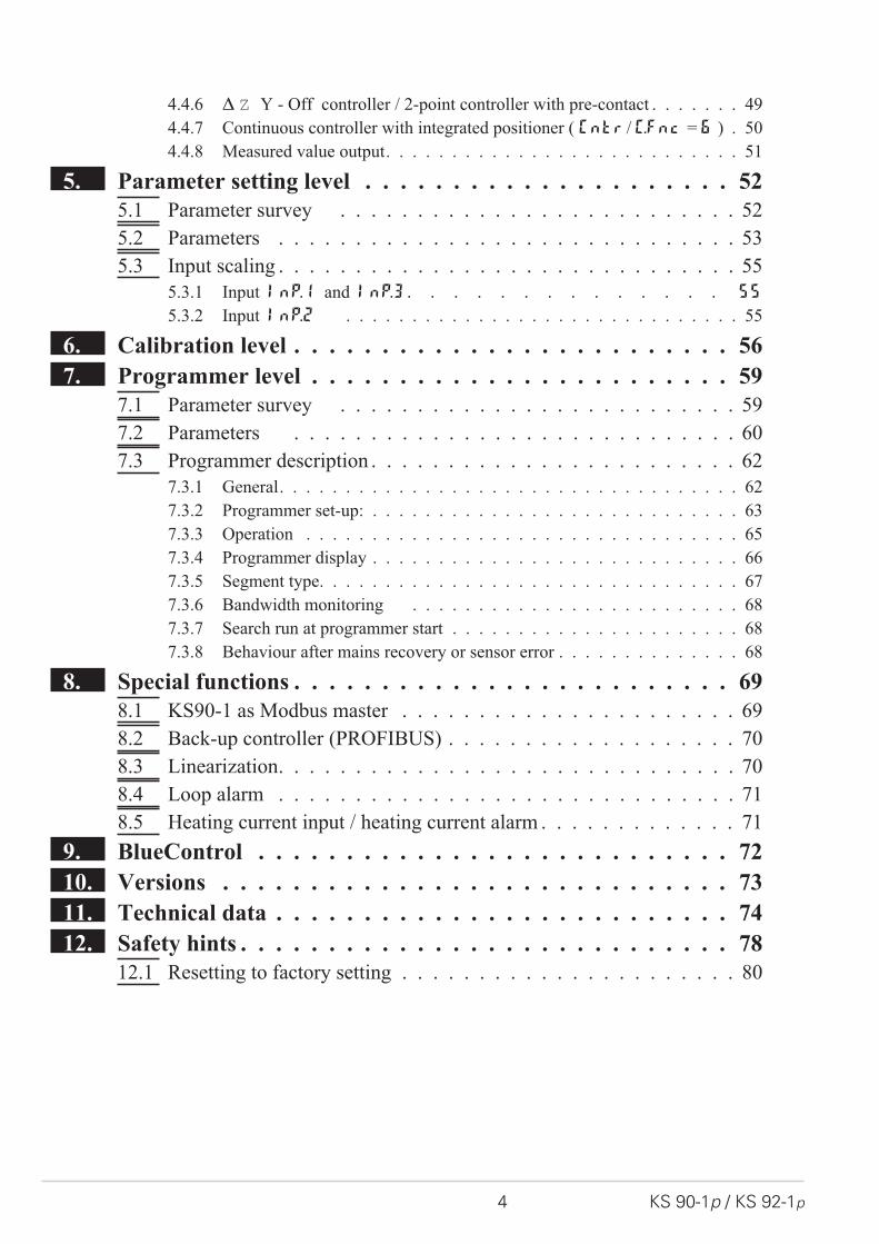
4.4.6 � � Y - Off controller / 2-point controller with pre-contact . . . . . . . 49
4.4.7 Continuous controller with integrated positioner ( Cntr/ C.Fnc = 6 ) . 50
4.4.8 Measured value output. . . . . . . . . . . . . . . . . . . . . . . . . . . 51
5. Parameter setting level . . . . . . . . . . . . . . . . . . . . . 52
5.1 Parameter survey . . . . . . . . . . . . . . . . . . . . . . . . . . 52
5.2 Parameters . . . . . . . . . . . . . . . . . . . . . . . . . . . . . . 53
5.3 Input scaling . . . . . . . . . . . . . . . . . . . . . . . . . . . . . . 55
5.3.1 Input Inp.1 and InP.3 . . . . . . . . . . . . . . 55
5.3.2 Input InP.2 . . . . . . . . . . . . . . . . . . . . . . . . . . . . . . 55
6. Calibration level . . . . . . . . . . . . . . . . . . . . . . . . . 56
7. Programmer level . . . . . . . . . . . . . . . . . . . . . . . . 59
7.1 Parameter survey . . . . . . . . . . . . . . . . . . . . . . . . . . 59
7.2 Parameters . . . . . . . . . . . . . . . . . . . . . . . . . . . . . 60
7.3 Programmer description . . . . . . . . . . . . . . . . . . . . . . . . 62
7.3.1 General. . . . . . . . . . . . . . . . . . . . . . . . . . . . . . . . . . . 62
7.3.2 Programmer set-up: . . . . . . . . . . . . . . . . . . . . . . . . . . . . 63
7.3.3 Operation . . . . . . . . . . . . . . . . . . . . . . . . . . . . . . . . . 65
7.3.4 Programmer display . . . . . . . . . . . . . . . . . . . . . . . . . . . . 66
7.3.5 Segment type. . . . . . . . . . . . . . . . . . . . . . . . . . . . . . . . 67
7.3.6 Bandwidth monitoring . . . . . . . . . . . . . . . . . . . . . . . . . 68
7.3.7 Search run at programmer start . . . . . . . . . . . . . . . . . . . . . . 68
7.3.8 Behaviour after mains recovery or sensor error . . . . . . . . . . . . . . 68
8. Special functions . . . . . . . . . . . . . . . . . . . . . . . . . 69
8.1 KS90-1 as Modbus master . . . . . . . . . . . . . . . . . . . . . . 69
8.2 Back-up controller (PROFIBUS) . . . . . . . . . . . . . . . . . . . 70
8.3 Linearization. . . . . . . . . . . . . . . . . . . . . . . . . . . . . . 70
8.4 Loop alarm . . . . . . . . . . . . . . . . . . . . . . . . . . . . . . 71
8.5 Heating current input / heating current alarm . . . . . . . . . . . . . 71
9. BlueControl . . . . . . . . . . . . . . . . . . . . . . . . . . . 72
10. Versions . . . . . . . . . . . . . . . . . . . . . . . . . . . . . 73
11. Technical data . . . . . . . . . . . . . . . . . . . . . . . . . . 74
12. Safety hints . . . . . . . . . . . . . . . . . . . . . . . . . . . . 78
12.1 Resetting to factory setting . . . . . . . . . . . . . . . . . . . . . . 80
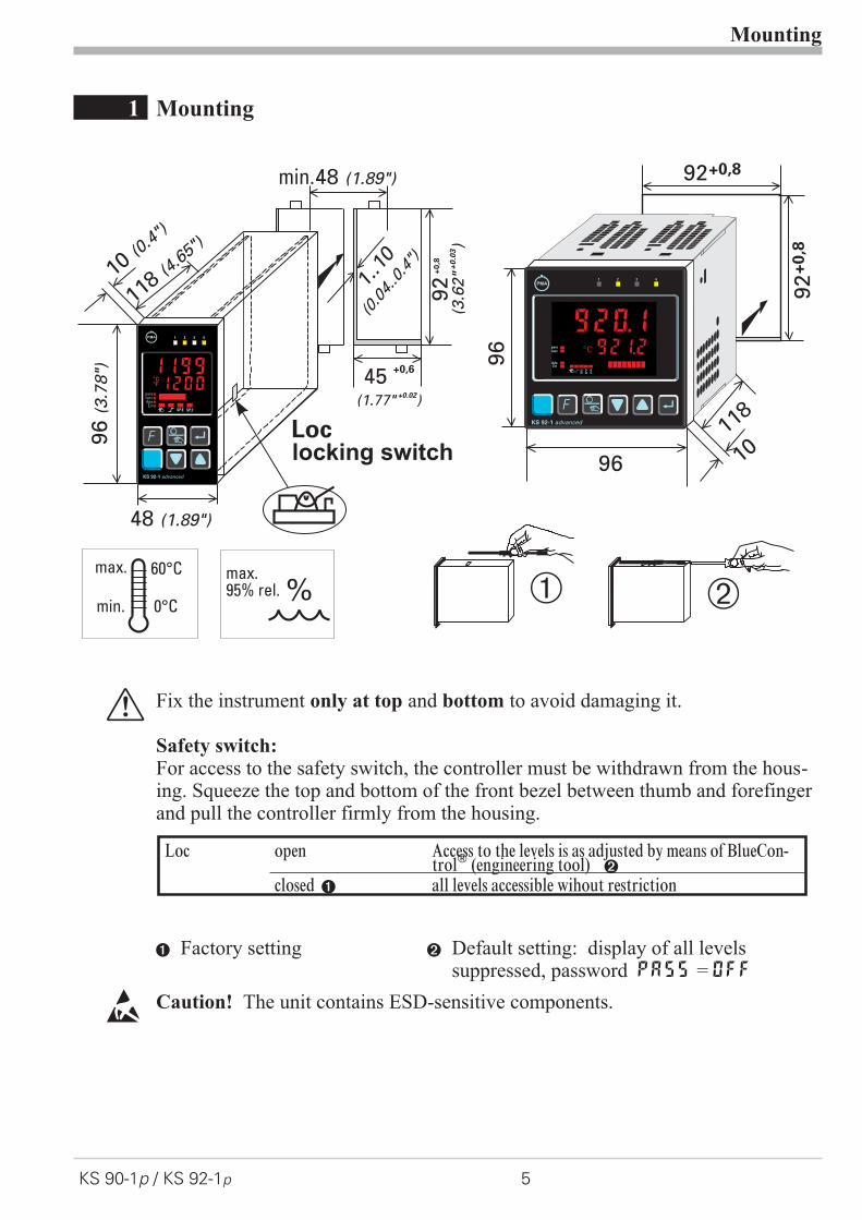
1 Mounting
a Fix the instrument only at top and bottom to avoid damaging it.
Safety switch:For access to the safety switch, the controller must be withdrawn from the hous-ing. Squeeze the top and bottom of the front bezel between thumb and forefingerand pull the controller firmly from the housing.
1 Factory setting 2 Default setting: display of all levelssuppressed, password PASS = OFF
l Caution! The unit contains ESD-sensitive components.
Mounting
KS 90-1p / KS 92-1p 5
%max.95% rel.
max. 60°C
0°Cmin.
96(3
.78")
48 (1.89")
Loc
min.48 (1.89")
10 (0.4
")
1..10
(0.04..0.4")
118 (4.6
5")
45 +0,6
(1.77" )+0.02
92+
0,8
(3.6
2"
)+
0.0
3
Ü *
KS 90-1 advanced
1 2 3
è
12001199°C°F
SP.2SP.E
parafuncAda
Err
4
12001199°C°F
SP.2SP.E
parafuncAda
Err
1 2 3 4
F
KS 92-1 advanced
F
92+0,8
92+
0,8
9696
10118
1 2 3 4
KS 92-1 advanced
F
SP.
E
SP.
2
run
920.1921.2C
parafunc
AdaErr
SP.
E
SP.
2
run
o
locking switch
Loc open Access to the levels is as adjusted by means of BlueCon-trol� (engineering tool) 2
closed 1 all levels accessible wihout restriction

2 Electrical connections
2.1 Connecting diagram
g Dependent of order, the controller is fitted with :
w flat-pin terminals 1 x 6,3mm or 2 x 2,8mm to DIN 46 244 or
w screw terminals for 0,5 to 2,5mm²On instruments with screw terminals, the insulation must be stripped by min.12 mm. Choose end crimps accordingly!
Electrical connections
Connecting diagram 6 KS 90-1p / KS 92-1p
1
3
4
5
6
7
8
9
10
11
12
13
14
15
17
(2)
(16)
mA
(mV)
(mV)
Volt
mA
INP2
INP3
INP1
di2
di1123
456
789
101112
131415
Op
tio
n
1
2
3
4
5
6
7
8
9
10
11
12
13
14
15
17(16)
OUT1
OUT2
OUT3
OUT4
90...250V
24 V UC
0%
100%
V
V
mAHC
KS90-1. -2
5
...
KS90-1. -4 ...
KS90-1. -5 ...
KS90-1..-.1...
di2
di3
UT
RXD-B
GND
RXD-A
TXD-B
TXD-A
RS485 RS422
Modbus RTU
RGND
DATA B
DATA A
9
0
8
3
2
17
6
5
4
a b c d e
f
g
ab cd
e
+24V DC
24V GND
OUT5OUT6
!
VP (5V)
DGND
RxD/TxD-N
RxD/TxD-P
PR
OF
IBU
S-D
PSchirm/Screen
59
48
37
26
1
59
48
37
26
1
390 [
390 [
220 [
DGND
VP (5V)
max.1200m
Adapte
r
Profibus DP
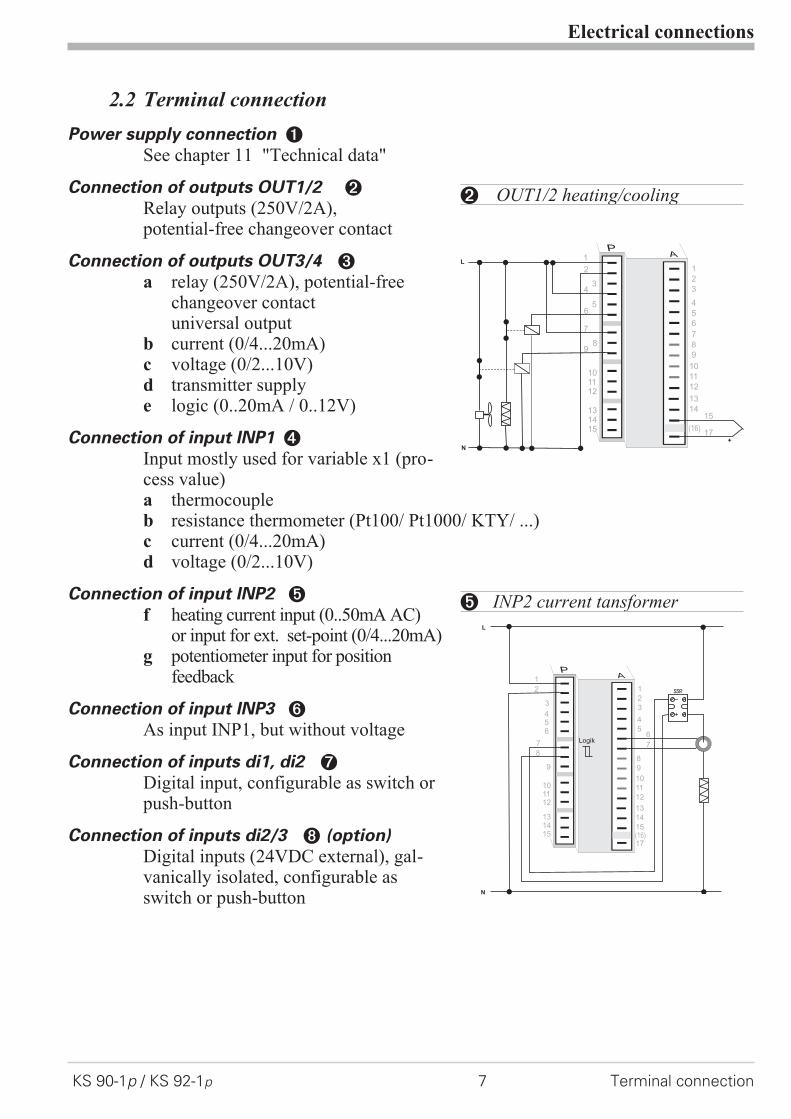
2.2 Terminal connection
Power supply connection 1
See chapter 11 "Technical data"
Connection of outputs OUT1/2 2
Relay outputs (250V/2A),potential-free changeover contact
Connection of outputs OUT3/4 3
a relay (250V/2A), potential-freechangeover contactuniversal output
b current (0/4...20mA)c voltage (0/2...10V)d transmitter supplye logic (0..20mA / 0..12V)
Connection of input INP1 4
Input mostly used for variable x1 (pro-cess value)a thermocoupleb resistance thermometer (Pt100/ Pt1000/ KTY/ ...)c current (0/4...20mA)d voltage (0/2...10V)
Connection of input INP2 5
f heating current input (0..50mA AC)or input for ext. set-point (0/4...20mA)
g potentiometer input for positionfeedback
Connection of input INP3 6
As input INP1, but without voltage
Connection of inputs di1, di2 7
Digital input, configurable as switch orpush-button
Connection of inputs di2/3 8 (option)
Digital inputs (24VDC external), gal-vanically isolated, configurable asswitch or push-button
Electrical connections
KS 90-1p / KS 92-1p 7 Terminal connection
6
9
101112
131415
1
2
3
4
5
6
7
8
9
10
11
12
13
14
17(16)
L
N
+
5
43
2
1
8
7
15
2 OUT1/2 heating/cooling
L
N
+
_SSR
3
456
9
101112
131415
1
2
3
4
5
8
9
10
11
12
13
14
15
17(16)
2
1
8
76
7Logik
5 INP2 current tansformer

Connection of output UT9 (option)
Supply voltage connection for external energization
Connection of outputs OUT5/6 0 (option)
Digital outputs (opto-coupler), galvanic isolated, common positive control volt-age, output rating: 18...32VDC
Connection of bus interface ! (option)
PROFIBUS DP or RS422/485 interface with Modbus RTU protocol
a Analog outputs OUT3 or OUT4 and transmitter supply UT are connected todifferent voltage potentials. Therefore, take care not to make an external galvanicconnection between OUT3/4 and UT with analog outputs!
Electrical connections
Terminal connection 8 KS 90-1p / KS 92-1p
131415
Op
tio
n
17(16)
1
3
4
5
6
7
8
9
10
11
12
13
14
15
17
(2)
(16)
+24VDC
5mA
5mA
0V
1
2
3
K
+
-
+-17,5V
22mA
14
13+
-15
OUT3
10
11
12
J
J
89 di2/3, 2-wire transmitter supply
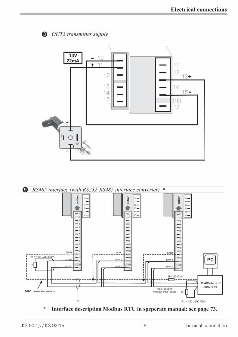
* Interface description Modbus RTU in speperate manual: see page 73.
Electrical connections
KS 90-1p / KS 92-1p 9 Terminal connection
1
3
4
5
6
7
8
9
10
11
12
13
14
15
17
(2)
(16)
op
tio
n
1
3
4
5
6
7
8
9
10
11
12
13
14
15
17
(2)
(16)
op
tio
n
1
3
4
5
6
7
8
9
10
11
12
13
14
15
17
(2)
(16)
op
tio
n
11
12
13
14
15
10
11
12
13
14
15
10
11
12
13
14
15
RGND RGND RGND
RT
RS485-RS232converter
PC
DATA A
DATA B
DATA A
DATA B
DATA A
DATA B
J
max. 1000m"Twisted Pair” cable
10
RT
R=100 Ohm
RGND connection optional
R = 120...200 OhmT
R = 120...200 OhmT
9 RS485 interface (with RS232-RS485 interface converter) *
1
2
3
K
+
-
+
-
13V22mA
131415
11
1213
17(16)
1415
12
11
10
3 OUT3 transmitter supply

KS90-1 connecting example:
a CAUTION: Using a temperature limiter is recommendable in
systems where overtemperature implies a fire hazard or
other risks.
Electrical connections
Terminal connection 10 KS 90-1p / KS 92-1p
+
_
L1
L2
N1
N2
fuse
1
2
3
4
7
5
8
6
9
10
11
12
13
14
15
fuse
1
fuse
SSR
reset
contactor
heating+ +
3
456
789
11
131415
1
2
3
4
5
6
7
8
9
10
11
12
13
14
17
(16)
15
2
1
12
10 Logik
KS90-1
TB
40-1
tem
pe
ratu
relim
ite
r
1 TB 40-1 Temperature limiterStandard version (3 relays):TB40-100-0000E-000
other versions on requestr
12
+
_SSR
+
_SSR
+
_SSR
Series connectionParallel connection
+
_SSR
+
_SSR
4V
4V
4V 12V
I =22mAmax
I =22mAmax
12V 11
1010
11
12
Logic
3 OUT3 as logic output with solid-state relay (series and parallel connection)

3 Operation
3.1 Front view
1 Statuses of switching outputsOuT.1...6 2 Process value display3 Setpoint or correcting variable display 4 °C or °F display signalling5 SignalsConF- andPArA level 6 Signals activated function key7 Selft-tuning active 8 Entry into the error list9 Bargraph or plain text display 0 Programmer running! Setpoint SP.2 is effective " Setpoint SP.E is effective§ Setpoint gradient is effective$ Manual-automatic switchover: Off: automatic On: manual mode (adjustment possible)
Blinks: manual mode (adjustment not possible (r ConF/Cntr/MAn))% Enter key: call up extented operating level / error list& Up/ down keys: changing setpoint or correcting variable/ Programmer: controller Run/Stop: automatic/manual or other functions (rConF /LOGI)( Switchover between programmer/controller operation or freely configurable function key with pure con-
troller operation) PC connection for BlueControl (engineering tool)
LED colours:LED 1, 2, 3, 4: yellowBargraph: redother LEDs: red
g In the upper display line, the process value is always displayed. At parameter,configuration, calibration as well as extended operating level, the bottom displayline changes cyclically between parameter name and parameter value.
Operation
KS 90-1p / KS 92-1p 11 Front view
1 2 3 4
FS
P.E
SP.
2
920.1921.2C
parafunc
AdaErr
SP.
E
SP.
2
run
o
12001199°C°F
SP.2SP.E
parafuncAda
Err
F
1 2 3 4 1 2 3 4
SP.
E
SP.
2
Cparafunc
AdaErr
SP.
E
SP.
2
run
o
12001199°C°F
parafuncAdaA
Err
1 2 3 4 1 2 3 4
SP.
E
SP.
2
Cparafunc
AdaErr
SP.
E
SP.
2
run
o
12001199°C°F
parafuncAda
Err
1 2 3 4
)
1
2
3456
%
78
&
/
)
1 2 3 4
SP.
E
SP.
2
Cparafunc
AdaErr
SP.
E
SP.
2
run
o
12001199°C°F
parafuncAda
Err
1 2 3 4 1 2 3 4
SP.
E
SP.
2
Cparafunc
AdaErr
SP.
E
SP.
2
run
o
12001199°C°F
parafuncAda
Err
1 2 3 4 1 2 3 4
SP.
E
SP.
2
Cparafunc
AdaErr
SP.
E
SP.
2
run
o
12001199°C°F
parafuncAda
Err
1 2 3 4 1 2 3 4
SP.
E
SP.
2
Cparafunc
AdaErr
SP.
E
SP.
2
run
o
12001199°C°F
parafuncAda
Err
1 2 3 4 1 2 3 4
SP.
E
SP.
2
Cparafunc
AdaErr
SP.
E
SP.
2
run
o
12001199°C°F
parafuncAda
Err
1 2 3 4
(
1 2 3 4
SP.
E
SP.
2
Cparafunc
AdaErr
SP.
E
SP.
2
run
o
12001199°C°F
parapfuncfAda
Err
1 2 3 4 1 2 3 4
SP.
E
SP.
2
Cparafunc
AdaErr
SP.
E
SP.
2
run
o
12001199°C°F
parafuncAda
Err
1 2 3 4 1 2 3 4
SP.
E
SP.
2
Cparafunc
AdaErr
SP.
E
SP.
2
run
o
12001199°C°F
parafuncAda
Err
1 2 3 4 1 2 3 4
SP.
E
SP.
2
Cparafunc
AdaErr
SP.
E
SP.
2
run
o
12001199°C°F
parafuncAda
Err
1 2 3 4 1 2 3 4
SP.
E
SP.
2
Cparafunc
AdaErr
SP.
E
SP.
2
run
o
12001199°C°F
parafuncAda
Err
1 2 3 4 1 2 3 4
SP.
E
SP.
2
Cparafunc
AdaErr
SP.
E
SP.
2
run
o
12001199°C°F
parafuncAda
Err
1 2 3 4
9
1 2 3 4
SP.
E
SP.
2
Cparafunc
AdaErr
SP.
E
SP.
2
run
o
12001199°C°F
parafuncAda
Err
1 2 3 4
$§"!0
1 2 3 4
SP.
E
SP.
2
Cparafunc
AdaErr
SP.
E
SP.
2
run
o
12001199°C°F
parafuncAda
Err
1 2 3 4 1 2 3 4
SP.
E
SP.
2
Cparafunc
AdaErr
SP.
E
SP.
2
run
o
12001199°C°F
parafuncAda
Err
1 2 3 4 1 2 3 4
SP.
E
SP.
2
Cparafunc
AdaErr
SP.
E
SP.
2
run
o
12001199°C°F
parafuncAda
Err
1 2 3 4
2
1 2 3 4
SP.
E
SP.
2
Cparafunc
AdaErr
SP.
E
SP.
2
run
o
12001199°C°F
parafuncAda
Err
1 2 3 4
5
3
4
1 2 3 4
SP.
E
SP.
2
Cparafunc
AdaErr
SP.
E
SP.
2
run
o
12001199°C°F
parafuncAda
Err
1 2 3 4 1 2 3 4
SP.
E
SP.
2
Cparafunc
AdaErr
SP.
E
SP.
2
run
o
12001199°C°F
parafuncAda
Err
1 2 3 4
99
1 2 3 4
SP.
E
SP.
2S
Cparafunc
AdaErr
SP.
E
SP.
2
run
o
12001199°C°F
parafuncAda
Err
1 2 3 4 1 2 3 4
SP.
E
SP.
2
Cparafunc
AdaErr
SP.
E
SP.
2
run
o
12001199°C°F
parafuncAda
Err
1 2 3 4
78
1 2 3 4
SP.
E
SP.
2
Cparafunc
AdaErr
SP.
E
SP.
2
run
o
12001199°C°F
parafuncAda
Err
1 2 3 4
%&/()
1 2 3 4
SP.
E
SP.
2
Cparafunc
AdaErr
SP.
E
SP.
2
run
o
12001199°C°F
parafuncAda
Err
1 2 3 4 1 2 3 4
SP.
E
SP.
2
Cparafunc
AdaErr
SP.
E
SP.
2
run
o
12001199°C°F
parafuncAda
Err
1 2 3 4
6
1 2 3 4
SP.
E
SP.
2
Cparafunc
AdaErr
SP.
E
SP.
2
run
o
12001199°C°F
parafuncAda
Err
1 2 3 4
556
1
2
3
1 2 3 4
SP.
E
SP.
2
Cparafunc
AdaErr
SP.
E
SP.
2
run
o
12001199°C°F
parafuncAda
Err
1 2 3 4
01 OFF
run
1 2 3 4
SP.
E
SP.
2
Cparafunc
AdaErr
SP.
E
SP.
2
run
o
12001199°C°F
parafuncAda
Err
1 2 3 4 1 2 3 4
SP.
E
SP.
2
Cparafunc
AdaErr
SP.
E
SP.
2
run
o
12001199°C°F
parafuncAda
Err
1 2 3 4
01 OFF$§"!0
1 2 3 4
SP.
E
SP.
2
Cparafunc
AdaErr
SP.
E
SP.
2
run
o
12001199°C°F
parafuncAda
Err
1 2 3 4 1 2 3 4
SP.
E
SP.
2
Cparafunc
AdaErr
SP.
E
SP.
2
run
o
12001199°C°F
parafuncAda
Err
1 2 3 4 1 2 3 4
SP.
E
SP.
2
Cparafunc
AdaErr
SP.
E
SP.
2
run
o
12001199°C°F
parafuncAda
Err
1 2 3 4
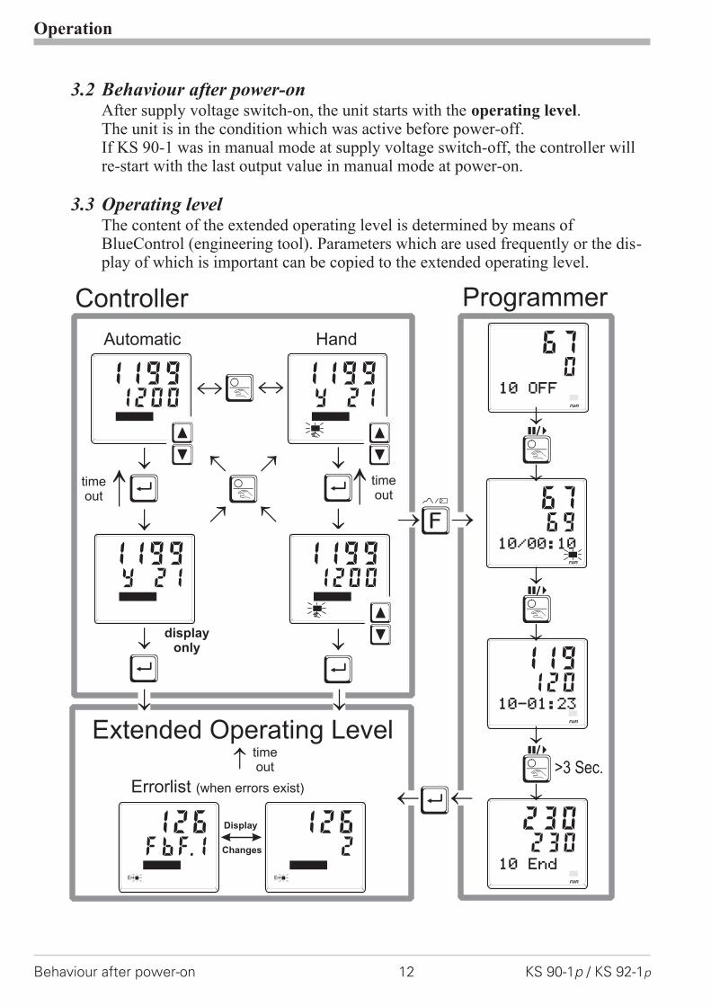
3.2 Behaviour after power-onAfter supply voltage switch-on, the unit starts with the operating level.The unit is in the condition which was active before power-off.If KS 90-1 was in manual mode at supply voltage switch-off, the controller willre-start with the last output value in manual mode at power-on.
3.3 Operating levelThe content of the extended operating level is determined by means ofBlueControl (engineering tool). Parameters which are used frequently or the dis-play of which is important can be copied to the extended operating level.
Operation
Behaviour after power-on 12 KS 90-1p / KS 92-1p
Ò
ÒÙ
Ù
Ù
Ù
Ù
Automatic
Extended Operating Level
Hand
è
ii
displayonly
Changes
Display
Errorlist (when errors exist)
Y 211199
12001199
120
230
119
230
ÈÌ
ÈÌ
Y 211199
12001199
ÈÌ
FbF.1126
Err
2126
Err
timeout
timeout
timeout
10-01:23
10 End
run
run
067
10 OFFrun
6967
10/00:10
run
Ò
Ò
Ò>3 Sec.
Controller Programmer
/

3.4 Error list / Maintenance managerWith one or several errors, the extended operating levelalways starts with the error list. Signalling an actual entryin the error list (alarm, error) is done by the Err LED inthe display. To reach the error list press Ù twice.
Error list:Name Description Reason Possible remedial actionE.1 Internal error,
cannot be removed- E.g. defective EEPROM - Contact West service
- Return unit to our factoryE.2 Internal error, can
be reset- e.g. EMC trouble - Keep measurement and power supply
cables in separate runs- Ensure that interference suppression of
contactors is providedE.3 Configuration error,
can be reset- wrong configuration- missing configuration
- Check interaction of configuration /parameters
E.4 Hardware error - Codenumber and hardware arenot identical
- Contact West service- Elektronic-/Optioncard must be exchanged
FbF.1 Sensor break INP1 - Sensor defective- Faulty cabling
- Replace INP1 sensor- Check INP1 connection
Sht.1 Short circuit INP1 - Sensor defective- Faulty cabling
- Replace INP1 sensor- Check INP1 connection
POL.1 INP1polarity error - Faulty cabling - Reverse INP1 polarityFbF.2 Sensor break INP2 - Sensor defective
- Faulty cabling- Replace INP2 sensor- Check INP2 connection
Sht.2 Short circuit INP2 - Sensor defective- Faulty cabling
- Replace sensor INP2- Check INP2 connection
POL.2 INP2 polarity - Faulty cabling - Reverse INP2 polarityFbF.3 Sensor break INP3 - Sensor defective
- Faulty cabling- Replace INP3 sensor- Check INP3 connection
Sht.3 Short circuit INP3 - Sensor defective- Faulty cabling
- Replace sensor INP3- Check INP3 connection
POL.3 INP3 polarity - Faulty cabling-
- Reverse INP3 polarity
HCA Heating currentalarm (HCA)
- Heating current circuitinterrupted, I< HC.A or I>HC.A (dependent ofconfiguration)
- Heater band defective
- Check heating current circuit- If necessary, replace heater band
Operation
KS 90-1p / KS 92-1p 13 Error list / Maintenance manager
12001199°C°F
SP.2SP.E
parafuncAda
Err
Err LED status Signification Proceed as followsblinks(status 2) Alarm due to
existing errorDetermine the error type in the error list Aftererror correction the unit changes to status 1
lit(status 1) Error removed, alarm not ack-nowledged
Acknowledge the alarm in the error list pressingkey ÈorÌ The alarm entry was deleted (status 0).
off(status 0) No error, all alarm entries deleted -Not visible except when acknowledging
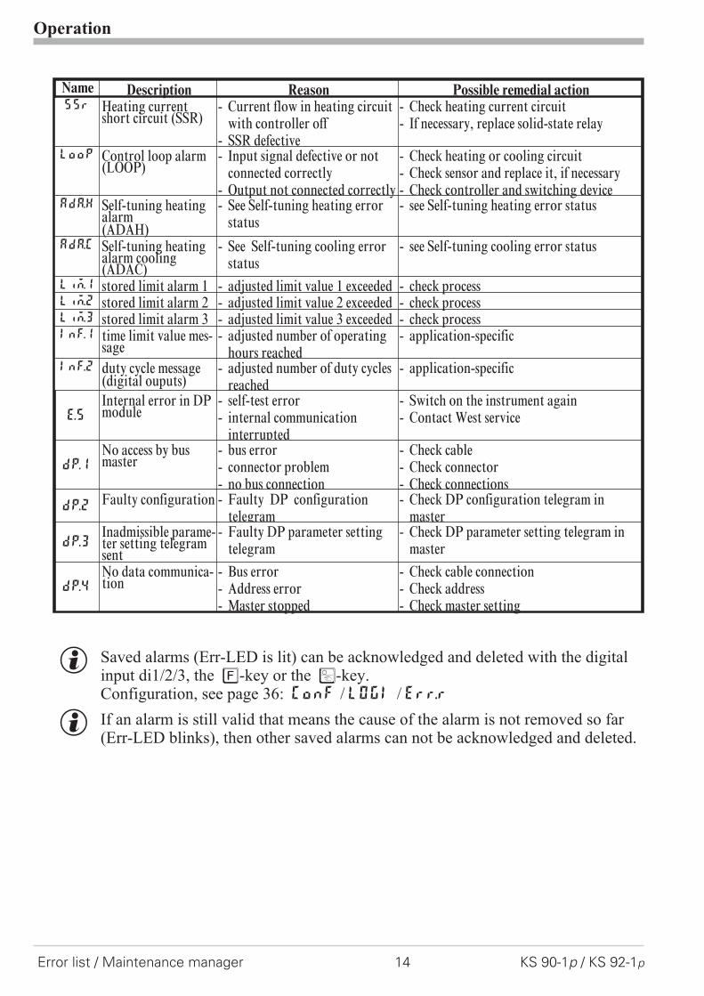
Name Description Reason Possible remedial actionSSr Heating current
short circuit (SSR)- Current flow in heating circuit
with controller off- SSR defective
- Check heating current circuit- If necessary, replace solid-state relay
LooP Control loop alarm(LOOP)
- Input signal defective or notconnected correctly
- Output not connected correctly
- Check heating or cooling circuit- Check sensor and replace it, if necessary- Check controller and switching device
AdA.H Self-tuning heatingalarm(ADAH)
- See Self-tuning heating errorstatus
- see Self-tuning heating error status
AdA.C Self-tuning heatingalarm cooling(ADAC)
- See Self-tuning cooling errorstatus
- see Self-tuning cooling error status
LiM.1 stored limit alarm 1 - adjusted limit value 1 exceeded - check processLim.2 stored limit alarm 2 - adjusted limit value 2 exceeded - check processLim.3 stored limit alarm 3 - adjusted limit value 3 exceeded - check processInf.1 time limit value mes-
sage- adjusted number of operating
hours reached- application-specific
Inf.2 duty cycle message(digital ouputs)
- adjusted number of duty cyclesreached
- application-specific
E.5
Internal error in DPmodule
- self-test error- internal communication
interrupted
- Switch on the instrument again- Contact West service
dp.1
No access by busmaster
- bus error- connector problem- no bus connection
- Check cable- Check connector- Check connections
dp.2Faulty configuration - Faulty DP configuration
telegram- Check DP configuration telegram in
master
dp.3Inadmissible parame-ter setting telegramsent
- Faulty DP parameter settingtelegram
- Check DP parameter setting telegram inmaster
dp.4
No data communica-tion
- Bus error- Address error- Master stopped
- Check cable connection- Check address- Check master setting
g Saved alarms (Err-LED is lit) can be acknowledged and deleted with the digitalinput di1/2/3, the è-key or the Ò-key.Configuration, see page 36: ConF / LOGI / Err.r
g If an alarm is still valid that means the cause of the alarm is not removed so far(Err-LED blinks), then other saved alarms can not be acknowledged and deleted.
Operation
Error list / Maintenance manager 14 KS 90-1p / KS 92-1p
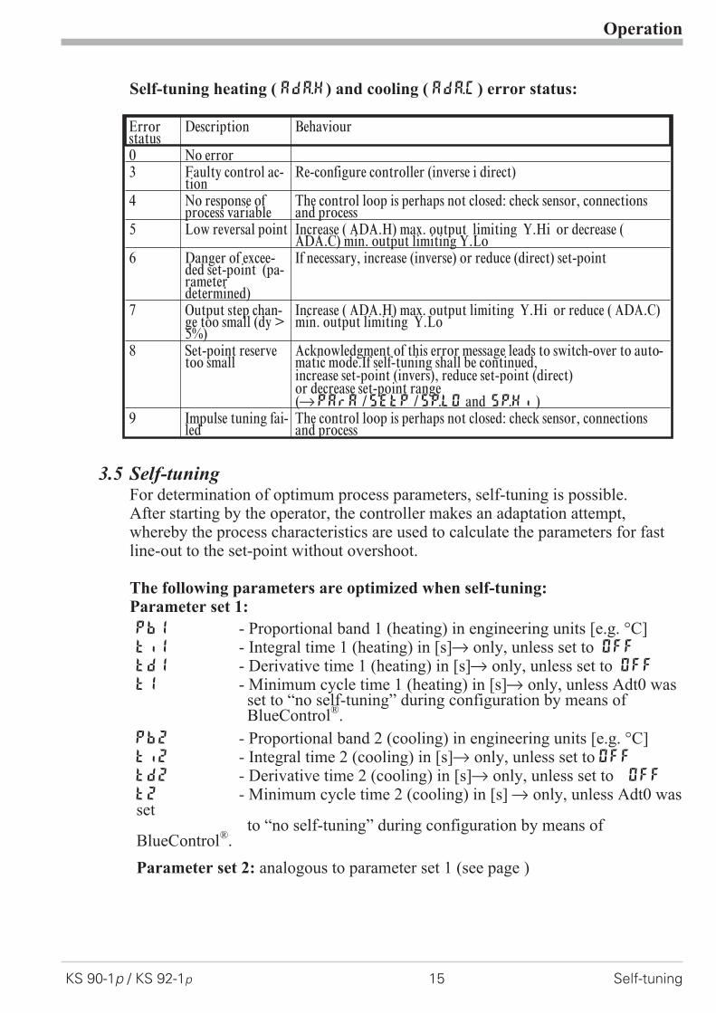
Self-tuning heating ( ADA.H) and cooling ( ADA.C) error status:
3.5 Self-tuningFor determination of optimum process parameters, self-tuning is possible.After starting by the operator, the controller makes an adaptation attempt,whereby the process characteristics are used to calculate the parameters for fastline-out to the set-point without overshoot.
The following parameters are optimized when self-tuning:Parameter set 1:
Pb1 - Proportional band 1 (heating) in engineering units [e.g. °C]ti1 - Integral time 1 (heating) in [s]r only, unless set to OFF
td1 - Derivative time 1 (heating) in [s]r only, unless set to OFF
t1 - Minimum cycle time 1 (heating) in [s]r only, unless Adt0 wasset to “no self-tuning” during configuration by means ofBlueControl®.
Pb2 - Proportional band 2 (cooling) in engineering units [e.g. °C]ti2 - Integral time 2 (cooling) in [s]r only, unless set to OFFtd2 - Derivative time 2 (cooling) in [s]r only, unless set to OFF
t2 - Minimum cycle time 2 (cooling) in [s] r only, unless Adt0 wasset
to “no self-tuning” during configuration by means ofBlueControl®.
Parameter set 2: analogous to parameter set 1 (see page )
Operation
KS 90-1p / KS 92-1p 15 Self-tuning
Errorstatus
Description Behaviour
0 No error3 Faulty control ac-
tionRe-configure controller (inverse i direct)
4 No response ofprocess variable
The control loop is perhaps not closed: check sensor, connectionsand process
5 Low reversal point Increase ( ADA.H) max. output limiting Y.Hi or decrease (ADA.C) min. output limiting Y.Lo
6 Danger of excee-ded set-point (pa-rameterdetermined)
If necessary, increase (inverse) or reduce (direct) set-point
7 Output step chan-ge too small (dy >5%)
Increase ( ADA.H) max. output limiting Y.Hi or reduce ( ADA.C)min. output limiting Y.Lo
8 Set-point reservetoo small
Acknowledgment of this error message leads to switch-over to auto-matic mode.If self-tuning shall be continued,increase set-point (invers), reduce set-point (direct)or decrease set-point range(rPArA /SEtp /SP.LO and SP.Hi )
9 Impulse tuning fai-led
The control loop is perhaps not closed: check sensor, connectionsand process

3.5.1 Preparation for self-tuning
Adjust the controller measuring range as control range limits. Setvalues rnG.L and rnG.H to the limits of subsequent control.(Configurationr Controllerrlower and upper control range limits)
ConFrCntrr rnG.L and rnG.H
w Determine which parameter set shall be optimized.- The instantaneously effective parameter set is optimized.
r Activate the relevant parameter set (1 or 2).
w Determine which parameter set shall be optimized (see tables above).
w Select the self-tuning methodsee chapter 3.5.3-Step attempt after start-up- Pulse attempt after start-up- Optimization at the set-point
3.5.2 Optimization after start-up or at the set-point
The two methods are optimization after start-up and at the set-point.As control parameters are always optimal only for a limited process range, vari-ous methods can be selected dependent of requirements. If the process behaviouris very different after start-up and directly at the set-point, parameter sets 1 and 2can be optimized using different methods. Switch-over between parameter setsdependent of process status is possible (see page ).
Optimization after start-up: (see page 4)Optimization after start-up requires a certain separation between process valueand set-point. This separation enables the controller to determine the control pa-rameters by evaluation of the process when lining out to the set-point.This method optimizes the control loop from the start conditions to the set-point,whereby a wide control range is covered.We recommend selecting optimization method “Step attempt after start-up”with tunE = 0 first. Unless this attempt is completed successfully, we recom-mend a “Pulse attempt after start-up”.
Optimization at the set-point: (see page 18)For optimizing at the set-point, the controller outputs a disturbance variable to theprocess. This is done by changing the output variable shortly. The process valuechanged by this pulse is evaluated. The detected process parameters are con-verted into control parameters and saved in the controller.This procedure optimizes the control loop directly at the set-point. The advantageis in the small control deviation during optimization.
Operation
Self-tuning 16 KS 90-1p / KS 92-1p

3.5.3 Selecting the method ( ConF/ Cntr/ tunE)
Selection criteria for the optimization method:
Step attempt after start-up Pulse attempt after start-up Optimization at the set-point
tunE= 0 sufficient set-point reserve isprovided
sufficient set-point reserve is notprovided
tunE= 1 sufficient set-point reserve isprovided
sufficient set-point reserve is notprovided
tunE= 2 always step attempt afterstart-up
Sufficient set-point reserve:inverse controller:(with process value < set-point- (10% of rnGH - rnGL)direct controller: (with process value > set-point + (10% of rnGH - rnGL)
3.5.4 Step attempt after start-up
Condition: - tunE = 0 and sufficient set-point reserve provided or- tunE = 2
The controller outputs 0% correcting variable or Y.Lo and waits, until the processis at rest (see start-conditions on page 8).Subsequently, a correcting variable step change to 100% is output.The controller attempts to calculate the optimum control parameters from the pro-cess response. If this is done successfully, the optimized parameters are takenover and used for line-out to the set-point.
With a 3-point controller, this is followed by “cooling”.After completing the 1st step as described, a correcting variable of -100% (100%cooling energy) is output from the set-point. After successfull determination ofthe “cooling parameters”, line-out to the set-point is using the optimized parame-ters.
3.5.5 Pulse attempt after start-up
Condition: - tunE = 1 and sufficient set-point reserve provided.
The controller outputs 0% correcting variable or Y.Lo and waits, until the processis at rest (see start conditions page 8)Subsequently, a short pulse of 100% is output (Y=100%) and reset.The controller attempts to determine the optimum control parameters from theprocess response. If this is completed successfully, these optimized parametersare taken over and used for line-out to the set-point.
With a 3-point controller, this is followed by “cooling”.After completing the 1st step as described and line-out to the set-point, correctingvariable "heating" remains unchanged and a cooling pulse (100% cooling energy)is output additionally. After successful determination of the “cooling parame-ters”, the optimized parameters are used for line-out to the set-point.
Operation
KS 90-1p / KS 92-1p 17 Self-tuning
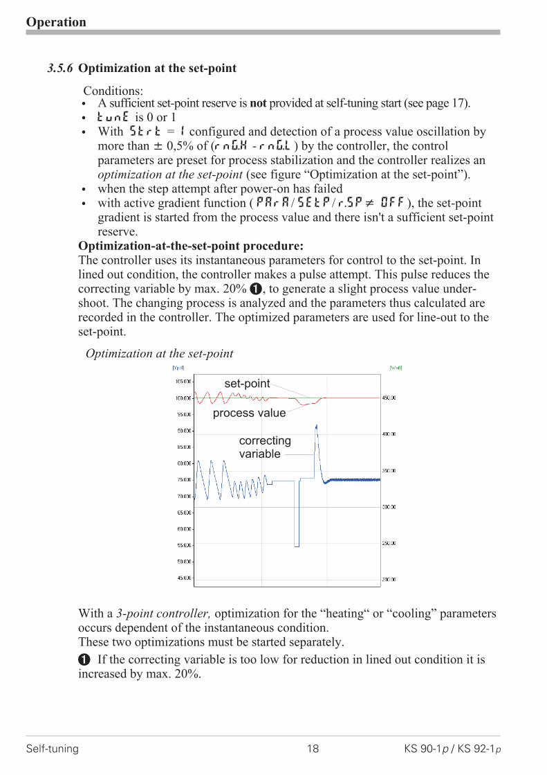
3.5.6 Optimization at the set-point
Conditions:w A sufficient set-point reserve is not provided at self-tuning start (see page 17).
w tunE is 0 or 1
w With Strt = 1 configured and detection of a process value oscillation bymore than � 0,5% of (rnG.H - rnG.L) by the controller, the controlparameters are preset for process stabilization and the controller realizes anoptimization at the set-point (see figure “Optimization at the set-point”).
w when the step attempt after power-on has failed
w with active gradient function ( PArA/ SETP/ r.SP� OFF), the set-pointgradient is started from the process value and there isn't a sufficient set-pointreserve.
Optimization-at-the-set-point procedure:The controller uses its instantaneous parameters for control to the set-point. Inlined out condition, the controller makes a pulse attempt. This pulse reduces thecorrecting variable by max. 20% 1, to generate a slight process value under-shoot. The changing process is analyzed and the parameters thus calculated arerecorded in the controller. The optimized parameters are used for line-out to theset-point.
With a 3-point controller, optimization for the “heating“ or “cooling” parametersoccurs dependent of the instantaneous condition.These two optimizations must be started separately.
1 If the correcting variable is too low for reduction in lined out condition it isincreased by max. 20%.
Operation
Self-tuning 18 KS 90-1p / KS 92-1p
set-point
process value
correctingvariable
Optimization at the set-point

3.5.7 Optimization at the set-point for 3-point stepping controller
With 3-point stepping controllers, the pulse attempt can be made with or withoutposition feedback. Unless feedback is provided, the controller calculates the mo-tor actuator position internally by varying an integrator with the adjusted actuatortravel time. For this reason, precise entry of the actuator travel time (tt), as timebetween stops is highly important. Due to position simulation, the controllerknows whether an increased or reduced pulse must be output. After supply volt-age switch-on, position simulation is at 50%. When the motor actuator was variedby the adjusted travel time in one go, internal calculation occurs, i.e. the positioncorresponds to the simulation:
Simulation actual position
Internal calculation tt
Internal calculation always occurs, when the actuator was varied by travel timett in one go , independent of manual or automatic mode. When interrupting thevariation, internal calculation is cancelled. Unless internal calculation occurredalready after self-tuning start, it will occur automatically by closing the actuatoronce.
Unless the positioning limits were reached within 10 hours, a significant devia-tion between simulation and actual position may have occurred. In this case, thecontroller would realize minor internal calculation, i.e. the actuator would beclosed by 20 %, and re-opened by 20 % subsequently. As a result, the controllerknows that there is a 20% reserve for the attempt.
Operation
KS 90-1p / KS 92-1p 19 Self-tuning
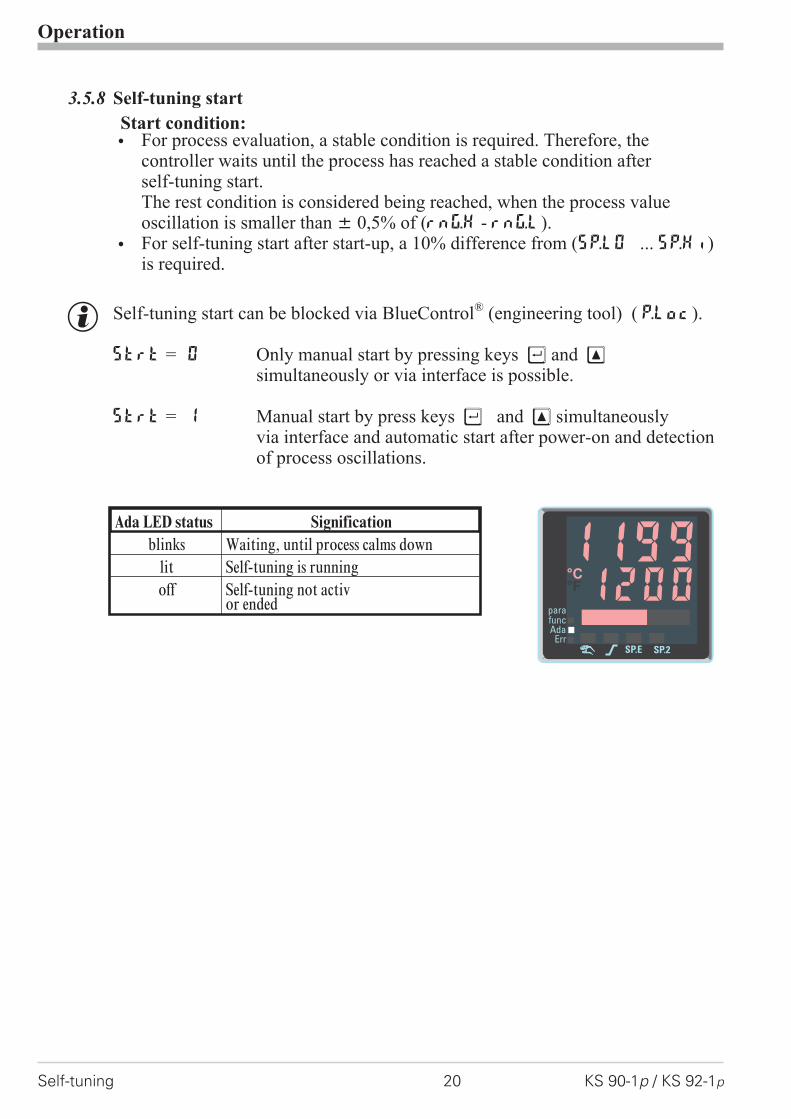
3.5.8 Self-tuning start
Start condition:w For process evaluation, a stable condition is required. Therefore, the
controller waits until the process has reached a stable condition afterself-tuning start.The rest condition is considered being reached, when the process valueoscillation is smaller than � 0,5% of (rnG.H - rnG.L).
w For self-tuning start after start-up, a 10% difference from (SP.LO ... SP.Hi)is required.
g Self-tuning start can be blocked via BlueControl® (engineering tool) ( P.Loc).
Strt = 0 Only manual start by pressing keys Ù and Èsimultaneously or via interface is possible.
Strt = 1 Manual start by press keys Ù and È simultaneouslyvia interface and automatic start after power-on and detectionof process oscillations.
Operation
Self-tuning 20 KS 90-1p / KS 92-1p
Ada LED status Signification
blinks Waiting, until process calms downlit Self-tuning is runningoff Self-tuning not activ
or ended 12001199°C°F
SP.2SP.E
parafuncAda
Err

3.5.9 Self-tuning cancellation
By the operator:Self-tuning can always be cancelled by the operator. For this, press Ù and Èkey simultaneously.With controller switch-over to manual mode after self-tuningstart, self-tuning is cancelled. When self-tuning is cancelled, the controller willcontinue operating using the old parameter values.
By the controller:If the Err LED starts blinking whilst self-tuning is running, successful self-tuningis prevented due to the control conditions. In this case, self-tuning was cancelledby the controller. The controller continues operating with the old parameters inautomatic mode. In manual mode it continues with the old controller outputvalue.
3.5.10 Acknowledgement procedures in case of unsuccessful self-tuning
1. Press keys Ù and È simultaneously:The controller continues controlling using the old parameters in automaticmode. The Err LED continues blinking, until the self-tuning error wasacknowledged in the error list.
2. Press key Ò (if configured):The controller goes to manual mode. The Err LED continues blinking,
until the self-tuning error was acknowleged in the error list.
3. Press key Ù :Display of error list at extended operating level. After acknowledgementof the error message, the controller continues control in automatic mode usingthe old parameters.
Cancellation causes:r page 15: "Error status self-tuning heating ( ADA.H) and cooling ( ADA.C)"
Operation
KS 90-1p / KS 92-1p 21 Self-tuning

3.5.11 Examples for self-tuning attempts
(controller inverse, heating or heating/cooling)
Start: heating power switched onHeating power Y is switched off (1).When the change of process value Xwas constant during one minute (2),the power is switched on (3).At the reversal point, the self-tuning at-tempt is finished and the new parameterare used for controlling to set-point W.
Start: heating power switched offThe controller waits 1,5 minutes (1).Heating power Y is switched on (2).At the reversal point, the self-tuningattempt is finished and control to theset-point is using the new parameters.
Self-tuning at the set-point aThe process is controlled to theset-point. With the control deviationconstant during a defined time (1)(i.e. constant separation of process valueand set-point), the controller outputs areduced correcting variable pulse (max.20%) (2). After determination of thecontrol parameters using the processcharacteristic (3), control is started us-ing the new parameters (4).
Three-point controller aThe parameter for heating and cooling aredetermined in two attempts. The heatingpower is switched on (1). Heating param-eters Pb1, ti1, td1 and t1 are deter-mined at the reversal point. Control to theset-point occurs(2). With constant controldeviation, the controller provides a coolingcorrecting variable pulse (3). After deter-mining its cooling parameters Pb2, ti2,td2 and t2 (4) from the process char-acteristics , control operation is started us-ing the new parameters (5).
a During phase 3, heating and cooling are done simultaneously!
Operation
Self-tuning 22 KS 90-1p / KS 92-1p
t
2
100%Y
0%
XW
Start r 1 3 t reversal point
blinks
t100%
Y0%
XW
start r 1 2 t reversal point
blinks
t
2
100%Y
0%
XW
1 3
blinks
4
r t
Start r
t+100%Y 0%-100%
XW
t reversalpoint
Start r 1 2
3
4 5
r t
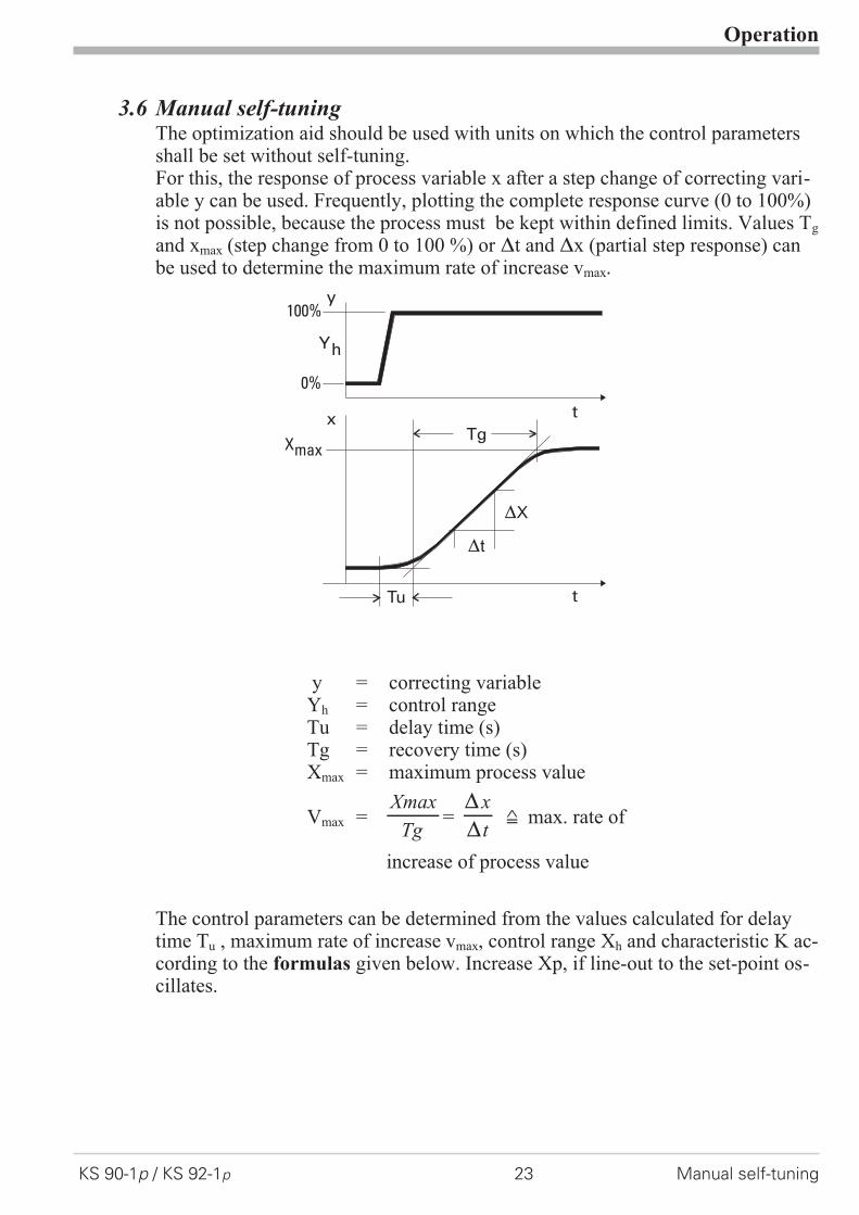
3.6 Manual self-tuningThe optimization aid should be used with units on which the control parametersshall be set without self-tuning.For this, the response of process variable x after a step change of correcting vari-able y can be used. Frequently, plotting the complete response curve (0 to 100%)is not possible, because the process must be kept within defined limits. Values Tg
and xmax (step change from 0 to 100 %) or �t and �x (partial step response) canbe used to determine the maximum rate of increase vmax.
The control parameters can be determined from the values calculated for delaytime Tu , maximum rate of increase vmax, control range Xh and characteristic K ac-cording to the formulas given below. Increase Xp, if line-out to the set-point os-cillates.
Operation
KS 90-1p / KS 92-1p 23 Manual self-tuning
Tu
Tg
t
x
y100%
0%
t
Yh
Xmax
{X
{t
y = correcting variableYh = control rangeTu = delay time (s)Tg = recovery time (s)Xmax = maximum process value
Vmax =Xmax
Tg={
{
x
t= max. rate of
increase of process value
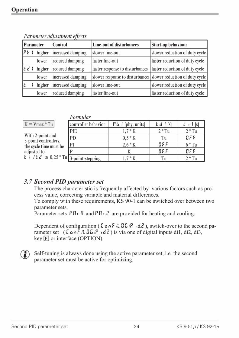
3.7 Second PID parameter setThe process characteristic is frequently affected by various factors such as pro-cess value, correcting variable and material differences.To comply with these requirements, KS 90-1 can be switched over between twoparameter sets.Parameter sets PArA and PAr.2 are provided for heating and cooling.
Dependent of configuration ( ConF/LOG/Pid.2), switch-over to the second pa-rameter set ( ConF/LOG/Pid.2) is via one of digital inputs di1, di2, di3,key è or interface (OPTION).
g Self-tuning is always done using the active parameter set, i.e. the secondparameter set must be active for optimizing.
Operation
Second PID parameter set 24 KS 90-1p / KS 92-1p
Parameter adjustment effects
Parameter Control Line-out of disturbances Start-up behaviour
Pb1 higher increased damping slower line-out slower reduction of duty cycle
lower reduced damping faster line-out faster reduction of duty cycle
td1 higher reduced damping faster response to disturbances faster reduction of duty cycle
lower increased damping slower response to disturbances slower reduction of duty cycle
ti1 higher increased damping slower line-out slower reduction of duty cycle
lower reduced damping faster line-out faster reduction of duty cycle
FormulasK = Vmax * Tu controller behavior Pb1 [phy. units] td1 [s] ti1 [s]
With 2-point and3-point controllers,the cycle time must beadjusted tot1 /t2 � 0,25 * Tu
PID 1,7 * K 2 * Tu 2 * TuPD 0,5 * K Tu OFF
PI 2,6 * K OFF 6 * TuP K OFF OFF
3-point-stepping 1,7 * K Tu 2 * Tu
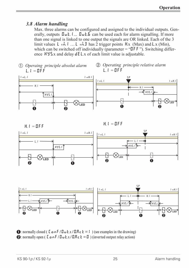
3.8 Alarm handlingMax. three alarms can be configured and assigned to the individual outputs. Gen-erally, outputs OuT.1... OuT.6 can be used each for alarm signalling. If morethan one signal is linked to one output the signals are OR linked. Each of the 3limit values Lim.1 … Lim.3 has 2 trigger points H.x (Max) and L.x (Min),which can be switched off individually (parameter = “OFF”). Switching differ-ence HYS.x and delay dEl.x of each limit value is adjustable.
1: normally closed ( ConF/Out.x /O.Act=1 ) (see examples in the drawing)2: normally open ( ConF/Out.x /O.Act=0 ) (inverted output relay action)
Operation
KS 90-1p / KS 92-1p 25 Alarm handling
L.1
LED
HYS.1
InL.1 InH.1
2 1
H.1 = OFF
L.1
LED
HYS.1
InL.1 InH.1
SP
2 1
H.1 = OFF
H.1
LED
HYS.1
InL.1 InH.1
21
Ü Operaing principle absolut alarm
L.1 = OFF
LED
HYS.1
H.1
InL.1 InH.1
SP
21
* Operating principle relative alarm
L.1 = OFF
L.1
LED LED
HYS.1 HYS.1
H.1
InL.1 InH.1
SP
2 21
L.1
LED LED
HYS.1 HYS.1
H.1
InL.1 InH.1
22 1
g The variable to be monitored can be selected seperately for each alarm viaconfigurationThe following variables can be monitored:
w process value
w control deviation xw (process value - set-point)
w control deviation xw + suppression after start-up or set-point changeAfter switching on or set-point changing, the alarm output is suppressed,until the process value is within the limits for the first time. At the latest afterexpiration of time 10 ti1, the alarm is activated. (ti1 = integral time 1;parameter r Cntr)If ti1 is switched off (ti1 = OFF), this is interpreted as Î, i.e. the alarm
is not activated, before the process value was within the limits once.
w Measured value INP1
w Measured value INP2
w Measured value INP3
w effective set-point Weff
w correcting variable y (controller output)
w Deviation from SP internal
w x1 - x2
w control deviation xw + suppression after start-up or setpoint changewithout time limit.- after switch-on or setpoint change, alarm output is suppressed, until theprocess value was within the limits once.
g If measured value monitoring + alarm status storage is chosen ( ConF / Lim /Fnc.x = 2/4), the alarm relay remains switched on until the alarm is resetted inthe error list ( Lim 1..3 = 1).
Operation
Alarm handling 26 KS 90-1p / KS 92-1p
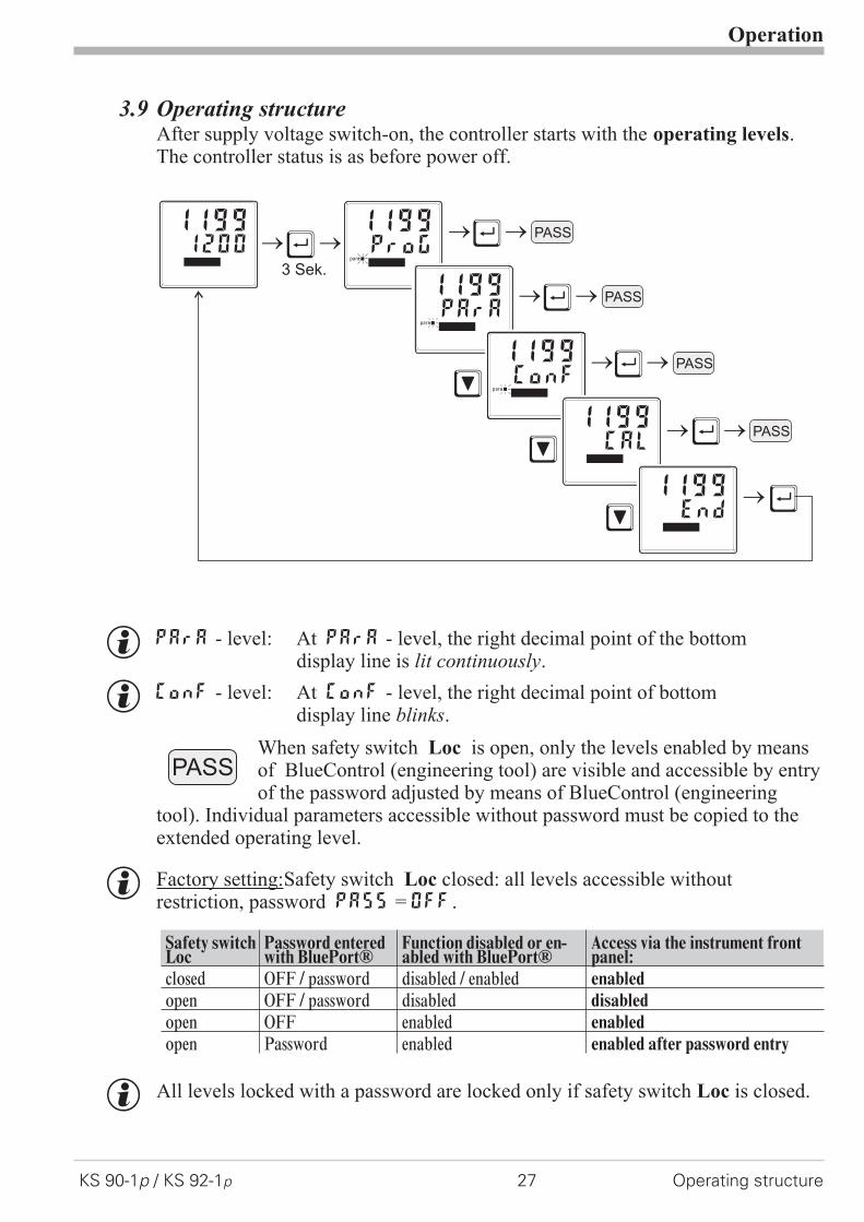
3.9 Operating structureAfter supply voltage switch-on, the controller starts with the operating levels.The controller status is as before power off.
g PArA - level: At PArA - level, the right decimal point of the bottomdisplay line is lit continuously.
g ConF - level: At ConF - level, the right decimal point of bottomdisplay line blinks.
When safety switch Loc is open, only the levels enabled by meansof BlueControl (engineering tool) are visible and accessible by entryof the password adjusted by means of BlueControl (engineering
tool). Individual parameters accessible without password must be copied to theextended operating level.
g Factory setting:Safety switch Loc closed: all levels accessible withoutrestriction, password PASS = OFF.
Safety switchLoc
Password enteredwith BluePort®
Function disabled or en-abled with BluePort®
Access via the instrument frontpanel:
closed OFF / password disabled / enabled enabled
open OFF / password disabled disabled
open OFF enabled enabled
open Password enabled enabled after password entry
g All levels locked with a password are locked only if safety switch Loc is closed.
Operation
KS 90-1p / KS 92-1p 27 Operating structure
ProG1199
para
Ù
Ù
Ù
Ù
Ù
Ù
Ì
Ì
Ì
3 Sek.
PASS
PASS12001199
PASS
PASS
PArA1199
para
ConF1199
para
CAL1199
End1199
PASS
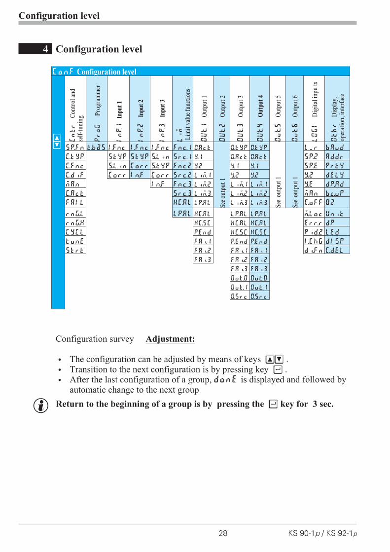
4 Configuration level
Configuration survey Adjustment:
w The configuration can be adjusted by means of keys ÈÌ .
w Transition to the next configuration is by pressing key Ù .
w After the last configuration of a group, donE is displayed and followed byautomatic change to the next group
g Return to the beginning of a group is by pressing the Ù key for 3 sec.
Configuration level
28 KS 90-1p / KS 92-1p
ConF Configuration level
ÈÌ
Cntr
Cont
rola
ndse
lf-tu
ning
Prog
Prog
ram
mer
InP.1
Inpu
t1
InP.2
Inpu
t2
InP.3
Inpu
t3
Lim
Lim
itva
luef
unct
ions
OUt.1
Out
put1
OUt.2
Out
put2
OUt.3
Out
put3
OUt.4
Out
put
4
Out.5
Out
put5
Out.6
Out
put6
LOGI
Dig
itali
npu
ts
Othr
Disp
lay,
oper
atio
n,in
terf
ace
SP.Fn t.bas I.Fnc I.Fnc I.Fnc Fnc.1 O.Act
Seeo
utpu
t1
O.tYP O.tYP
See
outp
ut1
See
outp
ut1
L_r bAud
C.tYP StYP StYP S.Lin Src.1 Y.1 O.Act O.Act SP.2 Addr
C.Fnc S.Lin Corr S.Typ Fnc.2 Y.2 Y.1 Y.1 SP.E PrtY
C.dif Corr In.F Corr Src.2 Lim.1 Y.2 Y.2 Y.2 dELY
mAn In.F Fnc.3 Lim.2 Lim.1 Lim.1 Y.E dp.Ad
C.Act Src.3 Lim.3 Lim.2 Lim.2 mAn bc.up
FAIL HC.AL LP.AL Lim.3 Lim.3 C.oFF O2
rnG.L LP.AL HC.AL LP.AL LP.AL m.Loc Unit
rnG.H HC.SC HC.AL HC.AL Err.r dP
CYCL P.End HC.SC HC.SC Pid.2 LEd
tunE FAi.1 P.End P.End I.Chg dISP
Strt FAi.2 FAi.1 FAi.1 di.Fn C.dEl
FAi.3 FAi.2 FAi.2
FAi.3 FAi.3
OuT.0 OuT.0
Out.1 Out.1
O.Src O.Src

4.1 Configuration parameters
Configuration level
KS 90-1p / KS 92-1p 29 Configuration parameters
q Cntr
Name Value range Description DefaultSP.Fn Basic configuration of setpoint processing 0
0 set-point controller can be switched over to external set-point(->LOGI/SP.E)
8 standard controller with external offset (SP.E)9 Programmer with external offset (SP.E)
C.tYP Calculation of the process value 00 standard controller (process value = x1)1 ratio controller (x1/x2)2 difference (x1 - x2)3 Maximum value of x1and x2. It is controlled with the bigger value.
At sensor failure it is controlled with the remaining actual value.4 Minimum value of x1and x2. It is controlled with the smaller value. At
sensor failure it is controlled with the remaining actual value.5 Mean value (x1, x2). With sensor error, controlling is continued
with the remaining process value.6 Switchover between x1 and x2 (->LOGI/I.ChG)7 O2 function with constant sensor temperature8 O2 function with measured sensor temperature
C.Fnc Control behaviour (algorithm) 10 on/off controller or signaller with one output1 PID controller (2-point and continuous)2 � / Y / Off, or 2-point controller with partial/full load switch-over3 2 x PID (3-point and continuous)4 3-point stepping controller5 3-point stepping controller with position feedback Yp6 continuous controller with integrated positioner
C.dif Output action of the PID controller derivative action 00 Derivative action acts only on the measured value.1 Derivative action only acts on the control deviation
(set-point is also differentiated)mAn Manual operation permitted 0
0 no1 yes (rLOGI /mAn)
C.Act Method of controller operation 00 inverse, e.g. heating
The correcting variable increases with decreasing process value anddecreases with increasing process value.
1 direct, e.g. coolingThe correcting variable increases with increasing process value anddecreases with decreasing process value.
FAIL Behaviour at sensor break 10 controller outputs switched off1 y = Y22 y = mean output. The maximum permissible output can be adjusted
with parameterYm.H. To prevent determination of inadmissible va-lues, mean value formation is only if the control deviation is lowerthan parameterL.Ym.
rnG.L -1999...9999 X0 (start of control range) 1 -100rnG.H -1999...9999 X100 (end of control range) 1 1200

Configuration level
Configuration parameters 30 KS 90-1p / KS 92-1p
Name Value range Description DefaultCYCL Characteristic for 2-point- and 3-point-controllers 0
0 standard3 with constant cycle
tunE Auto-tuning at start-up 00 At start-up with step attempt, at set-point with impulse attempt1 At start-up and at set-point with impulse attempt. Setting for fast
controlled systems (e.g. hot runner control)2 Always step attempt at start-up
Strt Start of auto-tuning 00 Manual start of auto-tuning1 Manual or automatic start of auto-tuning at power on or when oscil-
lating is detectedAdt0 Optimization of T1, T2 (only visible with BlueControl!) 0
0 Automatic optimization1 No optimization
1 rnG.L and rnG.H are indicating the range of control on which e.g. theself-tuning is refering
q Prog
Name Value Range Description Defaultt.bAS Timebase of Programmer 0
0 hours [hh] : minutes [mm]1 minutes [mm] : seconds [ss]
q InP.1
Name Value range Description DefaultI.fnc INP1 function selection 7
0 No function (following INP data are skipped)1 Heating current input2 External set-point SP.E (switch-over ->LOGI/SP.E)3 Position feedback Yp4 Second process value x2 (ratio, min, max, mean)5 External positioning value Y.E (switch-overrLOGI /Y.E)6 No controller input (e.g. limit signalling instead)7 Process value x1
S.tYP Sensor type selection 10 thermocouple type L (-100...900°C) , Fe-CuNi DIN1 thermocouple type J (-100...1200°C) , Fe-CuNi2 thermocouple type K (-100...1350°C), NiCr-Ni3 thermocouple type N (-100...1300°C), Nicrosil-Nisil4 thermocouple type S (0...1760°C), PtRh-Pt10%5 thermocouple type R (0...1760°C), PtRh-Pt13%6 thermocouple type T (-200...400°C), Cu-CuNi7 thermocouple type C (0...2315°C), W5%Re-W26%Re8 thermocouple type D (0...2315°C), W3%Re-W25%Re9 thermocouple type E (-100...1000°C), NiCr-CuNi
10 thermocouple type B (0/100...1820°C), PtRh-Pt6%18 special thermocouple
Configuration level
KS 90-1p / KS 92-1p 31 Configuration parameters
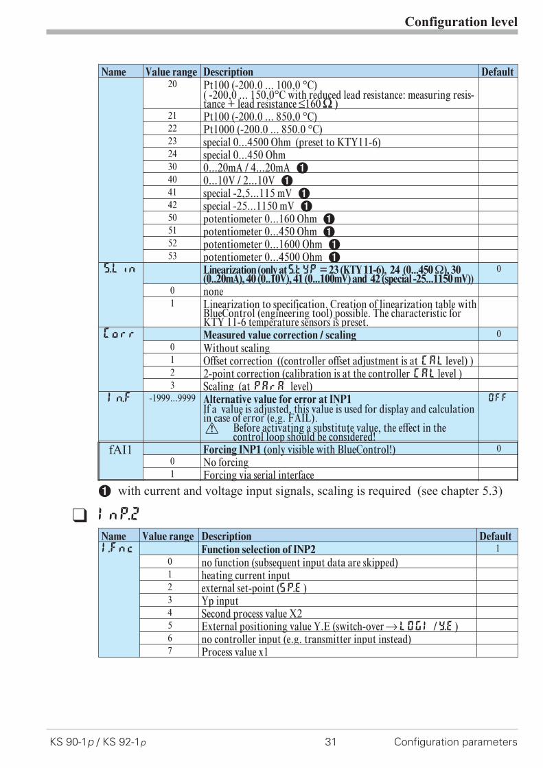
Name Value range Description Default20 Pt100 (-200.0 ... 100,0 °C)
( -200,0 ... 150,0°C with reduced lead resistance: measuring resis-tance + lead resistance ß160[ )
21 Pt100 (-200.0 ... 850,0 °C)22 Pt1000 (-200.0 ... 850.0 °C)23 special 0...4500 Ohm (preset to KTY11-6)24 special 0...450 Ohm30 0...20mA / 4...20mA 140 0...10V / 2...10V 141 special -2,5...115 mV 142 special -25...1150 mV 150 potentiometer 0...160 Ohm 151 potentiometer 0...450 Ohm 152 potentiometer 0...1600 Ohm 153 potentiometer 0...4500 Ohm 1
S.Lin Linearization (only atS.tYP= 23 (KTY 11-6), 24 (0...450�), 30(0..20mA), 40 (0..10V), 41 (0...100mV) and 42 (special -25...1150 mV))
0
0 none1 Linearization to specification. Creation of linearization table with
BlueControl (engineering tool) possible. The characteristic forKTY 11-6 temperature sensors is preset.
Corr Measured value correction / scaling 00 Without scaling1 Offset correction ((controller offset adjustment is at CALlevel) )2 2-point correction (calibration is at the controller CALlevel )3 Scaling (at PArA level)
In.f -1999...9999 Alternative value for error at INP1If a value is adjusted, this value is used for display and calculationin case of error (e.g. FAIL).a Before activating a substitute value, the effect in the
control loop should be considered!
OFF
fAI1 Forcing INP1 (only visible with BlueControl!) 00 No forcing1 Forcing via serial interface
1 with current and voltage input signals, scaling is required (see chapter 5.3)
q InP.2
Name Value range Description DefaultI.Fnc Function selection of INP2 1
0 no function (subsequent input data are skipped)1 heating current input2 external set-point (SP.E)3 Yp input4 Second process value X25 External positioning value Y.E (switch-overrLOGI /Y.E)6 no controller input (e.g. transmitter input instead)7 Process value x1

Configuration level
Configuration parameters 32 KS 90-1p / KS 92-1p
Name Value range Description DefaultS.tYP Sensor type selection 30
30 0...20mA / 4...20mA 131 0...50mA AC 150 Potentiometer ( 0...160 Ohm) 151 Potentiometer ( 0...450 Ohm) 152 Potentiometer ( 0...1600 Ohm) 153 Potentiometer ( 0...4500 Ohm) 1
Corr Measured value correction / scaling 00 Without scaling1 Offset correction (offset entry is at controller CALlevel)2 2-point correction ( calibration is at controller CALlevel)3 Scaling (at PArA level)
In.F -1999...9999 Alternative value for error at INP2If a value is adjusted, this value is used for display and calculationin case of error (e.g. FAIL).a Before activating a substitute value, the effect in the
control loop should be considered!
OFF
fAI2 Forcing INP2 (only visible with BlueControl!) 00 No forcing1 Forcing via serial interface
1 with current and voltage input signals, scaling is required (see chapter 5.3)
q InP.3
Name Value range Description DefaultI.Fnc Function selection of INP3 1
0 no function (subsequent input data are skipped)1 heating current input2 External set-point SP.E (switch-over ->LOGI/SP.E)3 Yp input4 Second process value X25 External positioning value Y.E (switch-overrLOGI /Y.E)6 no controller input (e.g. transmitter input instead)7 Process value x1
S.Lin Linearization(onlyatS.tYP=30(0..20mA)and40(0..10V)adjustable) 00 none1 Linearization to specification. Creation of linearization table with
BlueControl (engineering tool) possible. The characteristic forKTY 11-6 temperature sensors is preset.
S.tYP Sensor type selection 300 thermocouple type L (-100...900°C) , Fe-CuNi DIN1 thermocouple type J (-100...1200°C) , Fe-CuNi2 thermocouple type K (-100...1350°C), NiCr-Ni3 thermocouple type N (-100...1300°C), Nicrosil-Nisil4 thermocouple type S (0...1760°C), PtRh-Pt10%5 thermocouple type R (0...1760°C), PtRh-Pt13%6 thermocouple type T (-200...400°C), Cu-CuNi7 thermocouple type C (0...2315°C), W5%Re-W26%Re8 thermocouple type D (0...2315°C), W3%Re-W25%Re9 thermocouple type E (-100...1000°C), NiCr-CuNi
10 thermocouple type B (0/100...1820°C), PtRh-Pt6%18 special thermocouple
Configuration level
KS 90-1p / KS 92-1p 33 Configuration parameters
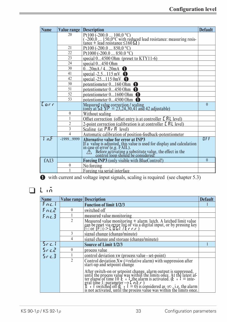
Name Value range Description Default20 Pt100 (-200.0 ... 100,0 °C)
( -200,0 ... 150,0°C with reduced lead resistance: measuring resis-tance + lead resistance ß160[ )
21 Pt100 (-200.0 ... 850,0 °C)22 Pt1000 (-200.0 ... 850.0 °C)23 special 0...4500 Ohm (preset to KTY11-6)24 special 0...450 Ohm30 0...20mA / 4...20mA 141 special -2,5...115 mV 142 special -25...115 0mV 150 potentiometer 0...160 Ohm 151 potentiometer 0...450 Ohm 152 potentiometer 0...1600 Ohm 153 potentiometer 0...4500 Ohm 1
Corr Measured value correction / scaling(only atS.tYP= 23,24,30,41 and 42 adjustable)
0
0 Without scaling1 Offset correction (offset entry is at controller CALlevel)2 2-point correction (calibration is at controller CALlevel)3 Scaling (at PArA level)4 Automatic calibration of position-feedback-potentiometer
In.F -1999...9999 Alternative value for error at INP3If a value is adjusted, this value is used for display and calculationin case of error (e.g. FAIL).a Before activating a substitute value, the effect in the
control loop should be considered!
OFF
fAI3 Forcing INP3 (only visible with BlueControl!) 00 No forcing1 Forcing via serial interface
1 with current and voltage input signals, scaling is required (see chapter 5.3)
q Lim
Name Value range Description DefaultFnc.1
Fnc.2
Fnc.3
Function of limit 1/2/3 10 switched off1 measured value monitoring2 Measured value monitoring + alarm latch. A latched limit value
can be reset via error list or via a digital input, or by pressing keyÒ or è (->LOGI/Err.r)
3 signal change (change/minute)4 signal change and storage (change/minute)
Src.1
Src.2
Src.3
Source of Limit 1/2/3 10 process value1 control deviation xw (process value - set-point)2 Control deviation Xw (=relative alarm) with suppression after
start-up and setpoint changeAfter switch-on or setpoint change, alarm output is suppressed,until the process value was within the limits once. At the latest af-ter elapse of time 10 ti1 the alarm is activated. (ti1= inte-gral time 1; parameterrCntr)ti1 switched off (ti1= 0) is considered as Î , i.e. the alarmis not activated, until the process value was within the limits once.

Configuration level
Configuration parameters 34 KS 90-1p / KS 92-1p
Name Value range Description Default3 measured value INP14 measured value INP25 measured value INP36 effective setpoint Weff7 correcting variable y (controller output)8 control variable deviation xw (actual value - internal setpoint) =
deviation alarm to internal setpoint9 difference x1 - x2 (utilizable e.g. in combination with process va-
lue function “mean value” for recognizing aged thermocouples11 Control deviation (=relative alarm) with suppression after
start-up and setpoint change without time limitAfter switch-on or setpoint change, alarm output is suppressed,until the process was within the limits once.
HC.AL Alarm heat current function (INP2) 00 switched off1 Overload short circuit monitoring2 Break and short circuit monitoring
LP.AL Monitoring of control loop interruption for heating 00 switched off / inactive1 Active. If ti1=0 LOOP alarm is inactive!
Loop alarm active. A loop break is recognized, with Y=100% if2 x ti passes by without appropriate reaction of process value
Hour OFF...999999 Operating hours (only visible with BlueControl�!) OFF
Swit OFF...999999 Output switching cycles (only visible with BlueControl�!) OFF
q Out.1 and Out.2
Name Value range Description DefaultO.Act Method of operation of output OUT1 0
0 direct / normally open1 inverse / normally closed
Y.1
Y.2
Controller output Y1/Y2 10 not active1 active
Lim.1
Lim.2
Lim.3
Limit 1/2/3 signal 00 not active1 active
LP.AL Interruption alarm signal (LOOP) 00 not active1 active
HC.AL Heat current alarm signal 00 not active1 active
HC.SC Solid state relay (SSR) short circuit signal 00 not active1 active
P.EnD Message "Programm end" 00 not active1 active

Configuration level
KS 90-1p / KS 92-1p 35 Configuration parameters
Name Value range Description DefaultFAi.1
FAi.2
FAi.3
INP1/ INP2 / INP3 error signal 00 not active1 active
dP.Er PROFIBUS error 00 not active1 active: Profibus trouble, no communication with this
instrument.Prg.1
Prg.2
Prg.3
Prg.4
Programmer Control track 1/2/3/40 not active1 active
CAll Operator call0 not active1 active
fOut Forcing OUT1 (only visible with BlueControl!) 00 No forcing1 Forcing via serial interface
Configuration parameters Out.2 as Out.1 except for: Default Y.1 = 0 Y.2 = 1
q Out.3 and Out.4
Name Value range Description DefaultO.tYP Signal type selection OUT3 0
0 relay / logic (only visible with current/logic voltage)1 0 ... 20 mA continuous (only visible with current/logic/voltage)2 4 ... 20 mA continuous (only visible with current/logic/voltage)3 0...10 V continuous (only visible with current/logic/voltage)4 2...10 V continuous (only visible with current/logic/voltage)5 transmitter supply (only visible without OPTION)
O.Act Method of operation of output OUT3 (only visible when O.TYP=0) 10 direct / normally open1 inverse / normally closed
Y.1
Y.2
Controller output Y1/ Y2 (only visible when O.TYP=0) 00 not active1 active
Lim.1
Lim.2
Lim.3
Limit 1/2/3 signal (only visible when O.TYP=0) 10 not active1 active
LP.AL Interruption alarm signal (LOOP) (only visible when O.TYP=0) 00 not active1 active
HC.AL Heating current alarm signal (only visible when O.TYP=0) 00 not active1 active
HC.SC Solid state relay (SSR) short circuit signal (only visible when O.TYP=0) 00 not active1 active
P.EnD Message "Programm end" 00 not active1 active
Configuration level
Configuration parameters 36 KS 90-1p / KS 92-1p
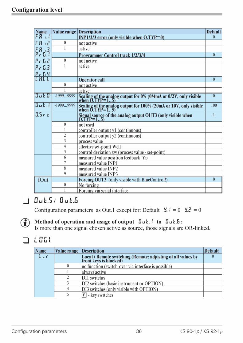
Name Value range Description DefaultFAi.1
FAi.2
FAi.3
INP1/2/3 error (only visible when O.TYP=0) 00 not active1 active
Prg.1
Prg.2
Prg.3
Prg.4
Programmer Control track 1/2/3/4 00 not active1 active
CAll Operator call 00 not active1 active
Out.0 -1999...9999 Scaling of the analog output for 0% (0/4mA or 0/2V, only visiblewhen O.TYP=1..5)
0
Out.1 -1999...9999 Scaling of the analog output for 100% (20mA or 10V, only visiblewhen O.TYP=1..5)
100
O.Src Signal source of the analog output OUT3 (only visible whenO.TYP=1..5)
1
0 not used1 controller output y1 (continuous)2 controller output y2 (continuous)3 process value4 effective set-point Weff5 control deviation xw (process value - set-point)6 measured value position feedback Yp7 measured value INP18 measured value INP29 measured value INP3
fOut Forcing OUT3 (only visible with BlueControl!) 00 No forcing1 Forcing via serial interface
q Out.5/ Out.6
Configuration parameters as Out.1 except for: Default Y.1 = 0 Y.2 = 0
g Method of operation and usage of output Out.1 to Out.6:Is more than one signal chosen active as source, those signals are OR-linked.
q LOGI
Name Value range Description DefaultL_r Local / Remote switching (Remote: adjusting of all values by
front keys is blocked)0
0 no function (switch-over via interface is possible)1 always active2 DI1 switches3 DI2 switches (basic instrument or OPTION)4 DI3 switches (only visible with OPTION)5 è - key switches

Configuration level
KS 90-1p / KS 92-1p 37 Configuration parameters
Name Value range Description DefaultSP.2 Switching to second setpointSP.2 0
0 no function (switch-over via interface is possible)2 DI1 switches3 DI2 switches (only visible with OPTION)4 DI3 switches (only visible with OPTION)5 è - key switches
SP.E Switching to external setpointSP.E 00 no function (switch-over via interface is possible)1 always active2 DI1 switches3 DI2 switches (only visible with OPTION)4 DI3 switches (only visible with OPTION)5 è - key switches
Y2 Y/Y2 switching 00 no function (switch-over via interface is possible)2 DI1 switches3 DI2 switches (only visible with OPTION)4 DI3 switches (only visible with OPTION)5 è - key switches6 Ò - key switches
Y.E Switching to fixed control outputY.E 00 no function (switch-over via interface is possible)1 always activated (manual station)2 DI1 switches3 DI2 switches (only visible with OPTION)4 DI3 switches (only visible with OPTION)5 è - key switches6 Ò - key switches
mAn Automatic/manual switching 00 no function (switch-over via interface is possible)1 always activated (manual station)2 DI1 switches3 DI2 switches (only visible with OPTION)4 DI3 switches (only visible with OPTION)5 è - key switches6 Ò - key switches
C.oFF Switching off the controller 00 no function (switch-over via interface is possible)2 DI1 switches3 DI2 switches (only visible with OPTION)4 DI3 switches (only visible with OPTION)5 è - key switches6 Ò - key switches
m.Loc Blockage of hand function 00 no function (switch-over via interface is possible)2 DI1 switches3 DI2 switches (only visible with OPTION)4 DI3 switches (only visible with OPTION)5 è - key switches
Configuration level
Configuration parameters 38 KS 90-1p / KS 92-1p
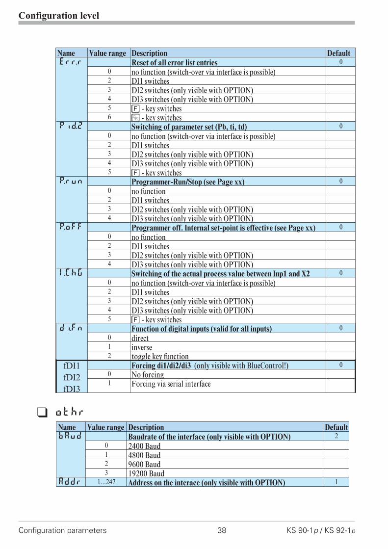
Name Value range Description DefaultErr.r Reset of all error list entries 0
0 no function (switch-over via interface is possible)2 DI1 switches3 DI2 switches (only visible with OPTION)4 DI3 switches (only visible with OPTION)5 è - key switches6 Ò - key switches
Pid.2 Switching of parameter set (Pb, ti, td) 00 no function (switch-over via interface is possible)2 DI1 switches3 DI2 switches (only visible with OPTION)4 DI3 switches (only visible with OPTION)5 è - key switches
P.run Programmer-Run/Stop (see Page xx) 00 no function2 DI1 switches3 DI2 switches (only visible with OPTION)4 DI3 switches (only visible with OPTION)
P.off Programmer off. Internal set-point is effective (see Page xx) 00 no function2 DI1 switches3 DI2 switches (only visible with OPTION)4 DI3 switches (only visible with OPTION)
I.Chg Switching of the actual process value between Inp1 and X2 00 no function (switch-over via interface is possible)2 DI1 switches3 DI2 switches (only visible with OPTION)4 DI3 switches (only visible with OPTION)5 è - key switches
di.Fn Function of digital inputs (valid for all inputs) 00 direct1 inverse2 toggle key function
fDI1
fDI2
fDI3
Forcing di1/di2/di3 (only visible with BlueControl!) 00 No forcing1 Forcing via serial interface
q othr
Name Value range Description DefaultbAud Baudrate of the interface (only visible with OPTION) 2
0 2400 Baud1 4800 Baud2 9600 Baud3 19200 Baud
Addr 1...247 Address on the interace (only visible with OPTION) 1

Configuration level
KS 90-1p / KS 92-1p 39 Configuration parameters
Name Value range Description DefaultPrtY Data parity on the interface (only visible with OPTION) 1
0 no parity (2 stop bits)1 even parity2 odd parity3 no parity (1 stopbit)
dP.Ad 0...126 PROFIBUS address 126bc.uP Back-up controller (see page )
0 No back-up controller1 Back-up controller
Delete line, order was faultydELY 0...200 Delay of response signal [ms] (only visible with OPTION) 0Unit Unit 1
0 without unit1 °C2 °F
dP Decimal point (max. number of digits behind the decimal point) 00 no digit behind the decimal point1 1 digit behind the decimal point2 2 digits behind the decimal point3 3 digits behind the decimal point
LED Function allocation of status LEDs 1 / 2 / 3 / 4 010 OUT1, OUT2, OUT3, OUT411 Heating, alarm 1, alarm 2, alarm 312 Heating, cooling, alarm 1, alarm 213 Cooling, heating, alarm 1, alarm 214 Bus error
dISP 0...10 Display luminosity 5C.dEl 0..200 Modem delay [ms]
Additional delay time, before the received message is evaluated inthe Modbus. This time is required, unless messages are transferredcontinuously during modem transmission.
0
dP.AD 0...126 Profibus address 126bc.up Behaviour as backup controller 0
0 No backup functionality1 With backup functionality
FrEq Switching 50 Hz / 60 Hz (only visible with BlueControl!) 00 50 Hz1 60 Hz
MAst Modbus master/slave (see page ) (visible only with BlueControl® ) 00 No1 Yes
CycL 0...240 Master cycle (sec.) (see page ) (visible only with BlueControl® !) 120
AdrO -32768...32767 Destination address (see page ) (visible only with BlueControl®!) 1100
AdrU -32768...32767 Source address (see page ) (visible only with BlueControl®!) 1100
Numb 0...100 Number of data (see page ) (visible only with BlueControl®!) 1
ICof Block controller off (only visible with BlueControl!) 00 Released1 Blocked

Configuration level
Configuration parameters 40 KS 90-1p / KS 92-1p
Name Value range Description Default
IAda Block auto tuning (only visible with BlueControl!) 00 Released1 Blocked
IExo Block extended operating level (only visible with BlueControl!) 00 Released1 Blocked
ILat Suppression error storage (visible only with BlueControl®!) 00 No: error message remain in the error list until
acknowledgement.1 Yes alarms are deleted from the error list as soon as
correctedPTmp Block temporary programm changes 0
0 Released1 Blocked
pPre Block Preset to end and reset 00 Released1 Blocked
pRun Block Run / Stop 00 Released1 Blocked
pSwi Block switch-over to controller 00 Released1 Blocked
pCom Block general p rogram-parameter (b.lo, b.Hi, d.00) 00 Released1 Blocked
Pass OFF...9999 Password (only visible with BlueControl!) OFF
IPar Block parameter level (only visible with BlueControl!) 00 Released1 Blocked
ICnf Block configuration level (only visible with BlueControl!) 00 Released1 Block
ICal Block calibration level (only visible with BlueControl!) 00 Released1 Blocked
CDis3 Display 3 controller operating level (only visible with BlueControl!) 20 No value / only text1 Display of value2 Output value as bargraph3 Control deviation as bargraph4 Process value as bargraph
TDis3 2...60 Display 3 display alternation time [s] (only visible with BlueControl!) 10
T.dis3 8 Zeichen Text display 3T.InF1 8 Zeichen Text Inf.1T.InF2 8 Zeichen Text Inf.2
g Resetting the controller configuration to factory setting (Default)r chapter (page )
+ BlueControl - the engineering tool for the BluePort�
controller series3 engineering tools with different functionality facilitating KS90-1configuration and parameter setting are available (see chapter 10: Accessoryequipment with ordering information).In addition to configuration and parameter setting, the engineering tools areused for data acquisition and offer long-term storage and print functions. Theengineering tools are connected to KS90-1 via the front-panel interface"BluePort�" by means of PC (Windows 95 / 98 / NT) and a PC adaptor.Description BlueControl: see chapter 9: BlueControl (page 72).
Configuration level
KS 90-1p / KS 92-1p 41 Configuration parameters
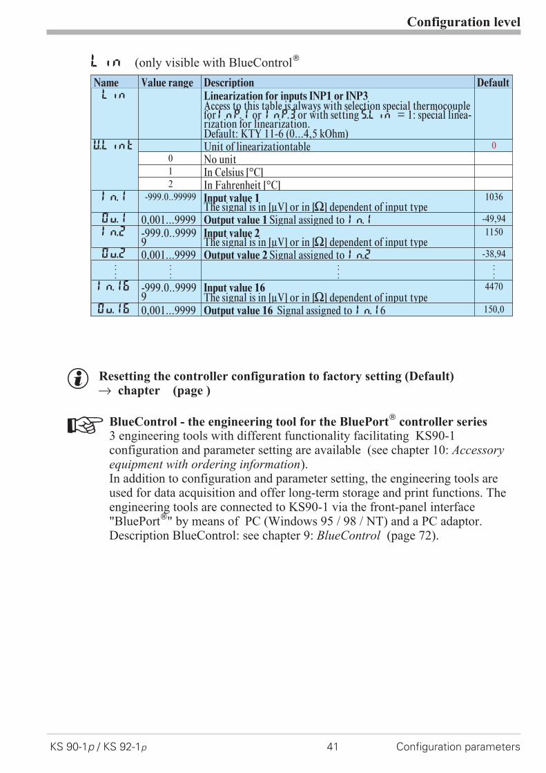
Lin (only visible with BlueControl�
Name Value range Description DefaultLin Linearization for inputs INP1 or INP3
Access to this table is always with selection special thermocoupleforInP.1 or InP.3or with settingS.Lin = 1: special linea-rization for linearization.Default: KTY 11-6 (0...4,5 kOhm)
U.LinT Unit of linearizationtable 00 No unit1 In Celsius [°C]2 In Fahrenheit [°C]
In.1 -999.0..99999 Input value 1The signal is in [µV] or in [[] dependent of input type
1036
Ou.1 0,001...9999 Output value 1 Signal assigned to In.1 -49,94In.2 -999.0..9999
9Input value 2The signal is in [µV] or in [[] dependent of input type
1150
Ou.2 0,001...9999 Output value 2 Signal assigned to In.2 -38,94::
::
::
::
In.16 -999.0..99999
Input value 16The signal is in [µV] or in [[] dependent of input type
4470
Ou.16 0,001...9999 Output value 16 Signal assigned to In.16 150,0
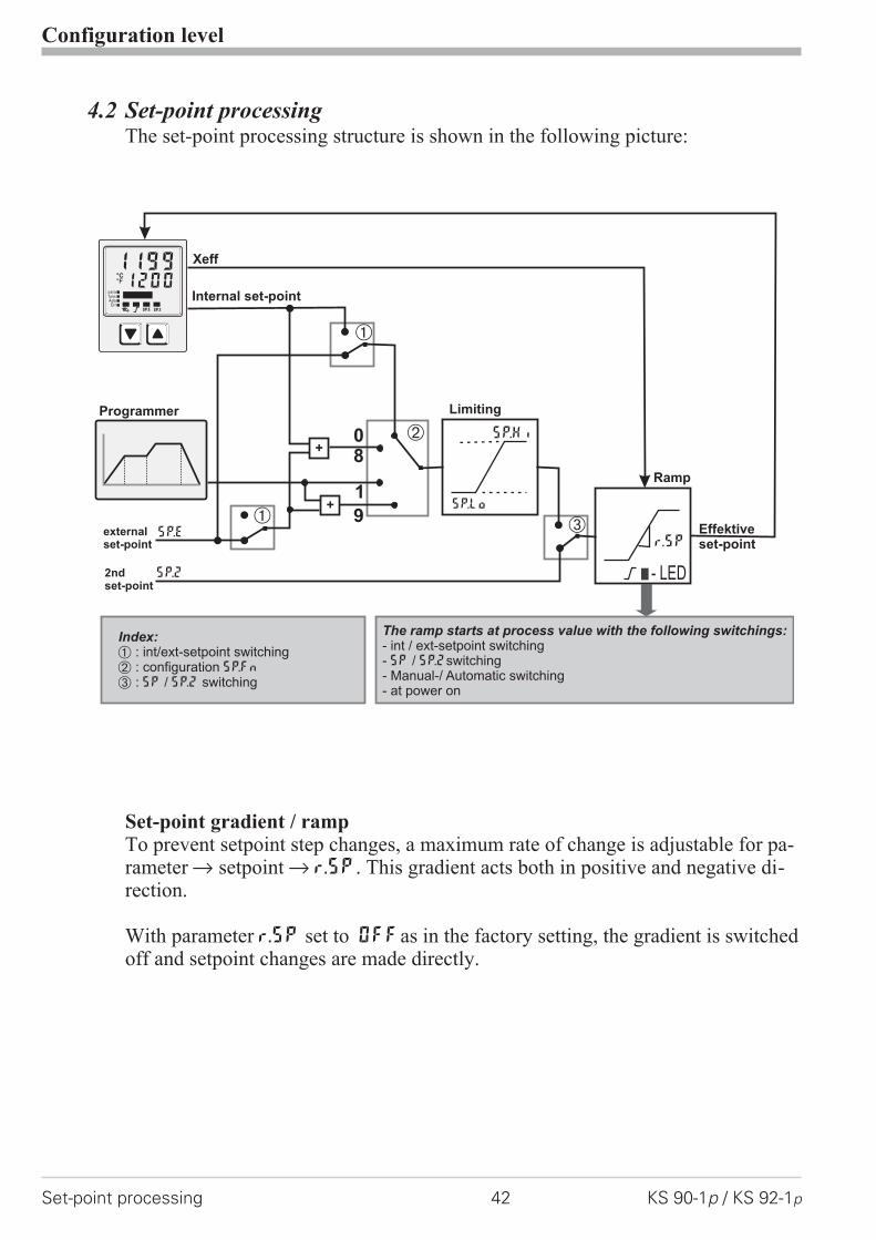
4.2 Set-point processingThe set-point processing structure is shown in the following picture:
Set-point gradient / rampTo prevent setpoint step changes, a maximum rate of change is adjustable for pa-rameter r setpoint r r.SP. This gradient acts both in positive and negative di-rection.
With parameter r.SP set to OFFas in the factory setting, the gradient is switchedoff and setpoint changes are made directly.
Configuration level
Set-point processing 42 KS 90-1p / KS 92-1p
0
1
Ü
Xeff
SP.2
SP.E
Internal set-point
Programmer
*
Ö
SP.Hi
SP.Lo
r.SP
- LED
externalset-point
Limiting
Ramp
2ndset-point
Effektiveset-point
Ü
+
+
8
9
12001199°C°F
SP.2SP.E
parafuncAda
Err
The ramp starts at process value with the following switchings:- int / ext-setpoint switching- / switching- Manual-/ Automatic switching- at power on
SP SP.2
Index:Ü*Ö
: int/ext-setpoint switching: configuration: / switching
SP.Fn
SP SP.2
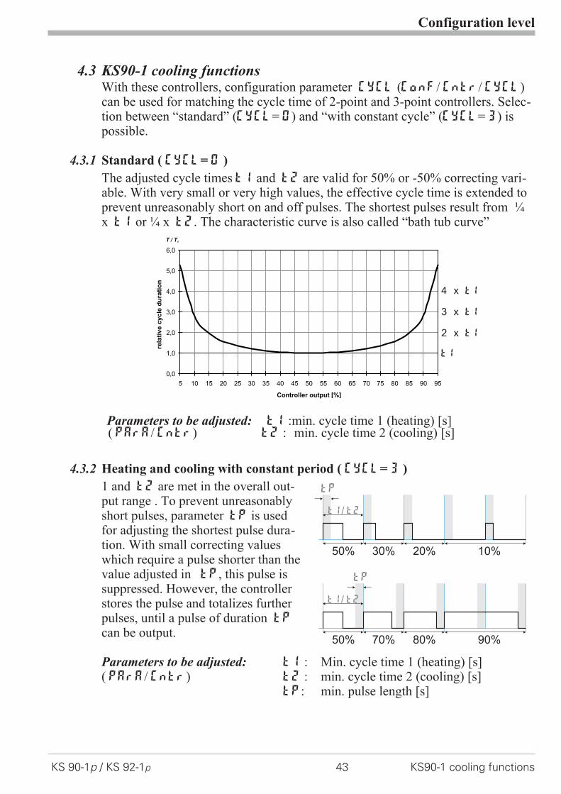
4.3 KS90-1 cooling functionsWith these controllers, configuration parameter CYCL (ConF/ Cntr/ CYCL)can be used for matching the cycle time of 2-point and 3-point controllers. Selec-tion between “standard” (CyCl= 0) and “with constant cycle” (CyCl= 3) ispossible.
4.3.1 Standard ( CyCl= 0 )
The adjusted cycle times t1 and t2 are valid for 50% or -50% correcting vari-able. With very small or very high values, the effective cycle time is extended toprevent unreasonably short on and off pulses. The shortest pulses result from ¼x t1 or ¼ x t2. The characteristic curve is also called “bath tub curve”
Parameters to be adjusted: t1 :min. cycle time 1 (heating) [s]( PArA/ Cntr) t2 : min. cycle time 2 (cooling) [s]
4.3.2 Heating and cooling with constant period ( CyCl= 3 )
1 and t2 are met in the overall out-put range . To prevent unreasonablyshort pulses, parameter tp is usedfor adjusting the shortest pulse dura-tion. With small correcting valueswhich require a pulse shorter than thevalue adjusted in tp, this pulse issuppressed. However, the controllerstores the pulse and totalizes furtherpulses, until a pulse of duration tp
can be output.
Parameters to be adjusted: t1 : Min. cycle time 1 (heating) [s]( PArA/ Cntr) t2 : min. cycle time 2 (cooling) [s]
tp: min. pulse length [s]
Configuration level
KS 90-1p / KS 92-1p 43 KS90-1 cooling functions
0,0
1,0
2,0
3,0
4,0
5,0
6,0
5 10 15 20 25 30 35 40 45 50 55 60 65 70 75 80 85 90 95
Controller output [%]
rela
tiv
ec
yc
led
ura
tio
n
T / T1
t1
2 x t1
3 x t1
4 x t1
50%
50%
t1 t2/
tp
tp
30%
70%
20%
80%
10%
90%
t1 t2/

4.4 Configuration examples
4.4.1 On-Off controller / Signaller (inverse)
ConF/Cntr: SP.Fn = 0 set-point controllerC.Fnc = 0 signaller with one outputC.Act = 0 inverse action (e.g. Heating
applications)ConF/Out.1: O.Act = 0 action Out.1 direct
Y.1 = 1 control output Y1 activePArA/Cntr: Hysl = 0...9999 switching difference (below
set-point)PArA/Cntr: HysH = 0...9999 switching difference (above
set-point)PArA/SEtP: SP.LO = -1999...9999 set-point limit low for Weff
SP.Hi = -1999...9999 set-point limit high for Weff
g For direct signaller action, the controller action must be changed(ConF / Cntr / C.Act = 1 )
Configuration level
Configuration examples 44 KS 90-1p / KS 92-1p
InH.1InL.1 SP.LO SP SP.Hi
100%
0%
SHOut.1Â
InP.1Ê
setpoint
output
process value
SH
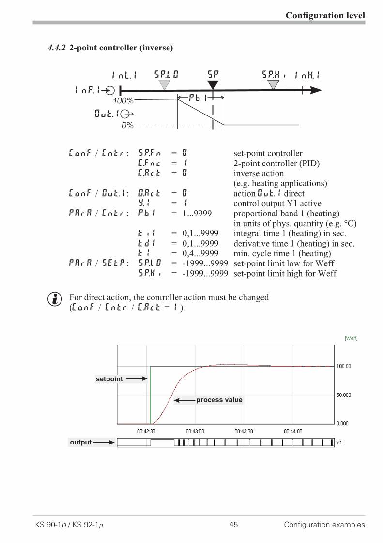
4.4.2 2-point controller (inverse)
ConF / Cntr: SP.Fn = 0 set-point controllerC.Fnc = 1 2-point controller (PID)C.Act = 0 inverse action
(e.g. heating applications)ConF / Out.1: O.Act = 0 action Out.1 direct
Y.1 = 1 control output Y1 activePArA / Cntr: Pb1 = 1...9999 proportional band 1 (heating)
in units of phys. quantity (e.g. °C)ti1 = 0,1...9999 integral time 1 (heating) in sec.td1 = 0,1...9999 derivative time 1 (heating) in sec.t1 = 0,4...9999 min. cycle time 1 (heating)
PArA / SEtP: SP.LO = -1999...9999 set-point limit low for WeffSP.Hi = -1999...9999 set-point limit high for Weff
g For direct action, the controller action must be changed(ConF / Cntr / C.Act = 1 ).
Configuration level
KS 90-1p / KS 92-1p 45 Configuration examples
InH.1InL.1 SP.LO SP SP.Hi
Out.1Â
InP.1Ê100%
0%
PB1
setpoint
output
process value
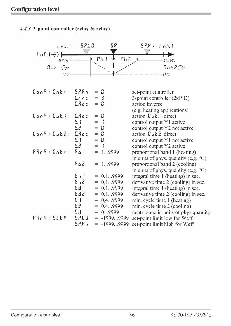
4.4.3 3-point controller (relay & relay)
ConF / Cntr: SP.Fn = 0 set-point controllerC.Fnc = 3 3-point controller (2xPID)C.Act = 0 action inverse
(e.g. heating applications)ConF / Out.1: O.Act = 0 action Out.1 direct
Y.1 = 1 control output Y1 activeY.2 = 0 control output Y2 not active
ConF / Out.2: O.Act = 0 action Out.2 directY.1 = 0 control output Y1 not activeY.2 = 1 control output Y2 active
PArA / Cntr: Pb1 = 1...9999 proportional band 1 (heating)in units of phys. quantity (e.g. °C)
Pb2 = 1...9999 proportional band 2 (cooling)in units of phys. quantity (e.g. °C)
ti1 = 0,1...9999 integral time 1 (heating) in sec.ti2 = 0,1...9999 derivative time 2 (cooling) in sec.td1 = 0,1...9999 integral time 1 (heating) in sec.td2 = 0,1...9999 derivative time 2 (cooling) in sec.t1 = 0,4...9999 min. cycle time 1 (heating)t2 = 0,4...9999 min. cycle time 2 (cooling)SH = 0...9999 neutr. zone in units of phys.quantity
PArA / SEtP: SP.LO = -1999...9999 set-point limit low for WeffSP.Hi = -1999...9999 set-point limit high for Weff
Configuration level
Configuration examples 46 KS 90-1p / KS 92-1p
InH.1InL.1 SP.LO SP SP.Hi
Out.1Â
InP.1Ê100%
0%
100%
0%
PB1 PB2
Out.2Â

4.4.4 3-point stepping controller (relay & relay)
ConF / Cntr: SP.Fn = 0 set-point controllerC.Fnc = 4 3-point stepping controllerC.Act = 0 inverse action
(e.g. heating applications)ConF / Out.1: O.Act = 0 action Out.1 direct
Y.1 = 1 control output Y1 activeY.2 = 0 control output Y2 not active
ConF / Out.2: O.Act = 0 action Out.2 directY.1 = 0 control output Y1 not activeY.2 = 1 control output Y2 active
PArA / Cntr: Pb1 = 1...9999 proportional band 1 (heating)in units of phys. quantity (e.g. °C)
ti1 = 0,1...9999 integral time 1 (heating) in sec.td1 = 0,1...9999 derivative time 1 (heating) in sec.t1 = 0,4...9999 min. cycle time 1 (heating)SH = 0...9999 neutral zone in units of phy. quantitytP = 0,1...9999 min. pulse length in sec.tt = 3...9999 actuator travel time in sec.
PArA / SEtP: SP.LO = -1999...9999 set-point limit low for WeffSP.Hi = -1999...9999 set-point limit high for Weff
g For direct action of the 3-point stepping controller, the controller output actionmust be changed ( ConF / Cntr / C.Act = 1 ).
Configuration level
KS 90-1p / KS 92-1p 47 Configuration examples
InH.1InL.1 SP.LO SP SP.Hi
Out.1Â
InP.1Ê
Out.2Â
100%
0%
100%
0%
PB1
SH
setpoint
output 1
process value
output 2
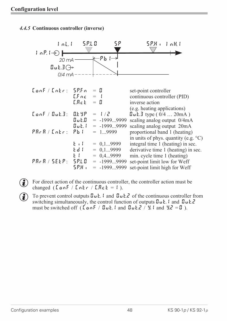
4.4.5 Continuous controller (inverse)
ConF / Cntr: SP.Fn = 0 set-point controllerC.Fnc = 1 continuous controller (PID)C.Act = 0 inverse action
(e.g. heating applications)ConF / Out.3: O.tYP = 1 / 2 Out.3 type ( 0/4 … 20mA )
Out.0 = -1999...9999 scaling analog output 0/4mAOut.1 = -1999...9999 scaling analog output 20mA
PArA / Cntr: Pb1 = 1...9999 proportional band 1 (heating)in units of phys. quantity (e.g. °C)
ti1 = 0,1...9999 integral time 1 (heating) in sec.td1 = 0,1...9999 derivative time 1 (heating) in sec.t1 = 0,4...9999 min. cycle time 1 (heating)
PArA / SEtP: SP.LO = -1999...9999 set-point limit low for WeffSP.Hi = -1999...9999 set-point limit high for Weff
g For direct action of the continuous controller, the controller action must bechanged ( ConF / Cntr / C.Act = 1 ).
g To prevent control outputs Out.1 and Out.2 of the continuous controller fromswitching simultaneously, the control function of outputs Out.1 and Out.2
must be switched off ( ConF / Out.1 and Out.2 / Y.1 and Y.2 = 0 ).
Configuration level
Configuration examples 48 KS 90-1p / KS 92-1p
InH.1InL.1 SP.LO SP SP.Hi
Out.3Â
InP.1Ê
20 mA
0/4 mA
PB1

4.4.6 � � Y - Off controller / 2-point controller with pre-contact
ConF / Cntr: SP.Fn = 0 set-point controllerC.Fnc = 2 � -Y-Off controllerC.Act = 0 inverse action
(e.g. heating applications)ConF / Out.1: O.Act = 0 action Out.1 direct
Y.1 = 1 control output Y1 activeY.2 = 0 control output Y2 not active
ConF / Out.2: O.Act = 0 action Out.2 directY.1 = 0 control output Y1 not activeY.2 = 1 control output Y2 active
PArA / Cntr: Pb1 = 1...9999 proportional band 1 (heating)in units of phys. quantity (e.g. °C)
ti1 = 0,1...9999 integral time 1 (heating) in sec.td1 = 0,1...9999 derivative time 1 (heating) in sec.t1 = 0,4...9999 min. cycle time 1 (heating)SH = 0...9999 switching differenced.SP = -1999...9999 trigg. point separation suppl. cont.
�/Y/Off in units of phys.quantityPArA / SEtP: SP.LO = -1999...9999 set-point limit low for Weff
SP.Hi = -1999...9999 set-point limit high for Weff
Configuration level
KS 90-1p / KS 92-1p 49 Configuration examples
InH.1InL.1 SP.LO SP SP.Hi
Out.1Â
InP.1Ê100%
0%
PB1
Out.2Â
d.SPSH

4.4.7 Continuous controller with integrated positioner ( Cntr/ C.Fnc = 6 )
( Cntr/ C.Fnc = 6 )
Basically, this controller function is a cascade. A slave controller with three-pointstepping behaviour working with position feedback Yp as process value (INP2 orINP3) is added to a continuous controller.ConF / Cntr SP.Fn = 0 setpoint controller
C.Fnc = 6 continuous controller withposition controller
C.Act = 0 inverse output action(e.g. heating applications)
ConF / InP.2: I.Fnc = 3 position feedback YpS.typ = 50 sensor e.g. potentiometer 0..160 �
ConF / Out.1: O.Act = 0 direct output action Out.1Y.1 = 1 control output Y1 activeY.2 = 0 control output Y2 not active
ConF / Out.2: O.Act = 0 direct output action Out.2Y.1 = 0 control output Y1 not activeY.2 = 1 control output Y2 active
PArA / Cntr: Pb1 = 0,1...9999 proportional band 1 (heating)in units of the physical quantity(e.g. °C)
ti1 = 1...9999 integral time 1 (heating) in sec.td1 = 1...9999 derivative time 1 (heating) in sec.t1 = 0,4...9999 min. cycle tim 1 (heating)SH = 0...9999 switching difference
Configuration level
Configuration examples 50 KS 90-1p / KS 92-1p
W
X M
OUT.4
OUT.1
OUT.2
INP.2
Ypid
Position controller
INP.1
Y.1
Y.2
Master controller
YcontinuousX
W
SP

4.4.8 Measured value output
ConF / Out.3 / 4: O.tYP = 1 Out.3/ 4 0...20mA continuous= 2 Out.3/ 4 4...20mA continuous= 3 Out.3/ 4 0...10V continuous= 4 Out.3/ 4 2...10V continuous
Out.0 = -1999...9999 scaling Out.3/ 4for 0/4mA or 0/2V
Out.1 = -1999...9999 scaling Out.3/ 4for 20mA or 10V
O.Src = 3 signal source for Out.3/ 4 isthe process value
Configuration level
KS 90-1p / KS 92-1p 51 Configuration examples
phys.quantity
mA / Vphys. quantity
Out.1
Out.0
0/4mA0/2V
20mA10V
1
456
789
10
1
2
3
4
5
6
7
8
9
10
11
12
13
14
17
(16)
+
L
N2
3
}90...250VAC24VUC
U
U
11
12
13
14
15
OUT3
OUT4INP1
15
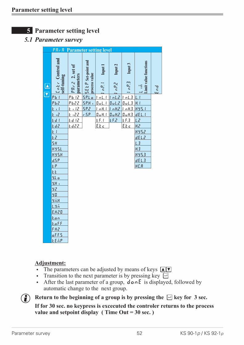
5 Parameter setting level
5.1 Parameter survey
Adjustment:
w The parameters can be adjusted by means of keys ÈÌ
w Transition to the next parameter is by pressing key Ù
w After the last parameter of a group, donE is displayed, followed byautomatic change to the next group.
g Return to the beginning of a group is by pressing the Ù key for 3 sec.
If for 30 sec. no keypress is excecuted the controler returns to the processvalue and setpoint display ( Time Out = 30 sec. )
Parameter setting level
Parameter survey 52 KS 90-1p / KS 92-1p
PArA Parameter setting level
È
Ì
Cntr
Con
trol
and
self
-tun
ing
PAr.2
2.se
tof
para
met
ers
SEtP
Set-
poin
tan
dpr
oces
sva
lue
InP.1
Inpu
t1
InP.2
Inpu
t2
InP.3
Inpu
t3
Lim
Lim
itva
lue
func
tion
s
End
Pb1 Pb12 SP.Lo InL.1 Inl.2 InL.3 L.1
Pb2 Pb22 SP.Hi OuL.1 OuL.2 OuL.3 H.1
ti1 ti12 SP.2 InH.1 InH.2 InH.3 HYS.1
ti2 ti22 r.SP OuH.1 OuH.2 OuH.3 dEl.1
td1 td12 tF.1 tF.2 tF.3 L.2
td2 td22 E.tc E.tc H.2
t1 HYS.2
t2 dEl.2
SH L.3
Hys.l H.3
Hys.H HYS.3
d.SP dEl.3
tP HC.A
tt
Y.Lo
Y.Hi
Y2
Y0
Ym.H
L.Ym
E.H2O
t.on
t.off
FH2
oFFS
tEmp
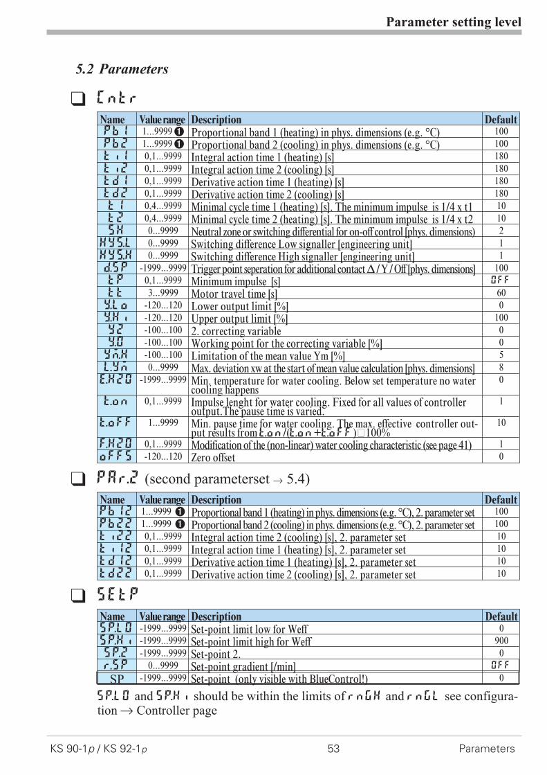
5.2 Parameters
Parameter setting level
KS 90-1p / KS 92-1p 53 Parameters
q Cntr
Name Valuerange Description DefaultPb1 1...99991 Proportional band 1 (heating) in phys. dimensions (e.g. °C) 100Pb2 1...99991 Proportional band 2 (cooling) in phys. dimensions (e.g. °C) 100ti1 0,1...9999 Integral action time 1 (heating) [s] 180ti2 0,1...9999 Integral action time 2 (cooling) [s] 180td1 0,1...9999 Derivative action time 1 (heating) [s] 180td2 0,1...9999 Derivative action time 2 (cooling) [s] 180t1 0,4...9999 Minimal cycle time 1 (heating) [s]. The minimum impulse is 1/4 x t1 10t2 0,4...9999 Minimal cycle time 2 (heating) [s]. The minimum impulse is 1/4 x t2 10SH 0...9999 Neutral zone or switching differential for on-off control [phys. dimensions) 2
Hys.l 0...9999 Switching difference Low signaller [engineering unit] 1Hys.H 0...9999 Switching difference High signaller [engineering unit] 1d.SP -1999...9999 Trigger point seperation for additional contact� / Y / Off [phys. dimensions] 100tP 0,1...9999 Minimum impulse [s] OFF
tt 3...9999 Motor travel time [s] 60Y.Lo -120...120 Lower output limit [%] 0Y.Hi -120...120 Upper output limit [%] 100Y2 -100...100 2. correcting variable 0Y.0 -100...100 Working point for the correcting variable [%] 0Ym.H -100...100 Limitation of the mean value Ym [%] 5L.Ym 0...9999 Max. deviation xw at the start of mean value calculation [phys. dimensions] 8E.H2O -1999...9999 Min. temperature for water cooling. Below set temperature no water
cooling happens0
t.on 0,1...9999 Impulse lenght for water cooling. Fixed for all values of controlleroutput.The pause time is varied.
1
t.oFF 1...9999 Min. pause time for water cooling. The max. effective controller out-put results fromt.on/(t.on+t.off)·100%
10
F.H2O 0,1...9999 Modification of the (non-linear) water cooling characteristic (see page 41) 1oFFS -120...120 Zero offset 0
q PAr.2 (second parameterset r 5.4)
Name Valuerange Description DefaultPb12 1...9999 1 Proportional band 1 (heating) in phys. dimensions (e.g. °C), 2. parameter set 100Pb22 1...9999 1 Proportional band 2 (cooling) in phys. dimensions (e.g. °C), 2. parameter set 100Ti22 0,1...9999 Integral action time 2 (cooling) [s], 2. parameter set 10Ti12 0,1...9999 Integral action time 1 (heating) [s], 2. parameter set 10Td12 0,1...9999 Derivative action time 1 (heating) [s], 2. parameter set 10Td22 0,1...9999 Derivative action time 2 (cooling) [s], 2. parameter set 10
q SEtP
Name Valuerange Description DefaultSP.LO -1999...9999 Set-point limit low for Weff 0SP.Hi -1999...9999 Set-point limit high for Weff 900SP.2 -1999...9999 Set-point 2. 0r.SP 0...9999 Set-point gradient [/min] OFF
SP -1999...9999 Set-point (only visible with BlueControl!) 0
SP.LO and SP.Hi should be within the limits of rnGH and rnGL see configura-tion r Controller page
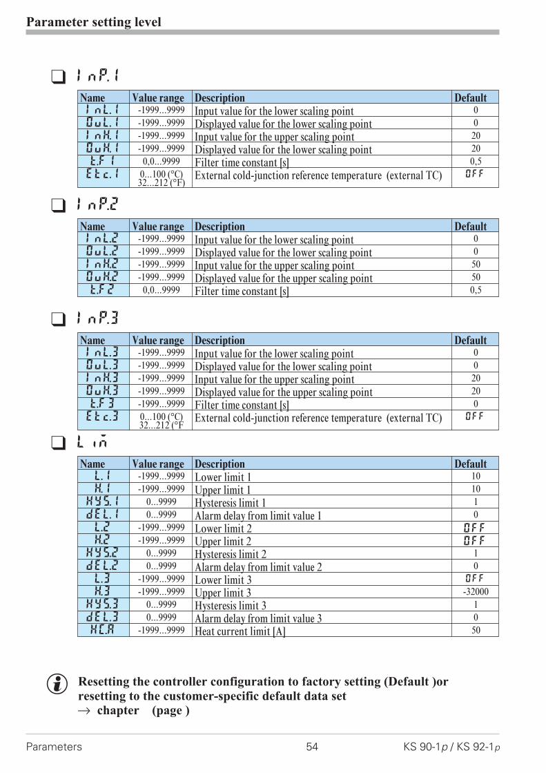
g Resetting the controller configuration to factory setting (Default )or
resetting to the customer-specific default data setr chapter (page )
Parameter setting level
Parameters 54 KS 90-1p / KS 92-1p
q InP.1
Name Value range Description DefaultInL.1 -1999...9999 Input value for the lower scaling point 0OuL.1 -1999...9999 Displayed value for the lower scaling point 0InH.1 -1999...9999 Input value for the upper scaling point 20OuH.1 -1999...9999 Displayed value for the lower scaling point 20t.F1 0,0...9999 Filter time constant [s] 0,5Etc.1 0...100 (°C)
32...212 (°F)External cold-junction reference temperature (external TC) OFF
q InP.2
Name Value range Description DefaultInL.2 -1999...9999 Input value for the lower scaling point 0OuL.2 -1999...9999 Displayed value for the lower scaling point 0InH.2 -1999...9999 Input value for the upper scaling point 50OuH.2 -1999...9999 Displayed value for the upper scaling point 50t.F2 0,0...9999 Filter time constant [s] 0,5
q InP.3
Name Value range Description DefaultInL.3 -1999...9999 Input value for the lower scaling point 0OuL.3 -1999...9999 Displayed value for the lower scaling point 0InH.3 -1999...9999 Input value for the upper scaling point 20OuH.3 -1999...9999 Displayed value for the upper scaling point 20t.F3 -1999...9999 Filter time constant [s] 0Etc.3 0...100 (°C)
32...212 (°FExternal cold-junction reference temperature (external TC) OFF
q Lim
Name Value range Description DefaultL.1 -1999...9999 Lower limit 1 10H.1 -1999...9999 Upper limit 1 10
HYS.1 0...9999 Hysteresis limit 1 1dEl.1 0...9999 Alarm delay from limit value 1 0L.2 -1999...9999 Lower limit 2 OFF
H.2 -1999...9999 Upper limit 2 OFF
HYS.2 0...9999 Hysteresis limit 2 1dEl.2 0...9999 Alarm delay from limit value 2 0L.3 -1999...9999 Lower limit 3 OFF
H.3 -1999...9999 Upper limit 3 -32000HYS.3 0...9999 Hysteresis limit 3 1dEl.3 0...9999 Alarm delay from limit value 3 0HC.A -1999...9999 Heat current limit [A] 50

5.3 Input scalingWhen using current, voltage or resistance signals as input variables for InP.1,InP.2 or/and InP.3 scaling of input and display values at parameter settinglevel is required. Specification of the input value for lower and higher scalingpoint is in the relevant electrical unit (mA/V/�).
5.3.1 Input Inp.1 and InP.3
g Parameters InL.x , OuL.x, InH.x and OuH.x are only visible ifConF / InP.x / Corr = 3 is chosen.
In addition to these settings, InL.x and InH.x can be adjusted in the range(0...20mA / 0...10V/ �) determined by selection of S.tYP .
a For using the predetermined scaling with thermocouple and resistancethermometer (Pt100), the settings for InL.x and OuL.x and for InH.x andOuH.x must have the same value.
g Input scaling changes at calibration level (r page 56) are displayed by inputscaling at parameter setting level. After calibration reset (OFF), the scalingparameters are reset to default.
5.3.2 Input InP.2
In addition to these settings, InL.2 and InH.2 can be adjusted in the range(0...20/ 50mA/�) determined by selection of S.tYP.
Parameter setting level
KS 90-1p / KS 92-1p 55 Input scaling
mA/V
phys.quantity
mA / V phys. quantity
OuH.x
OuL.x
InH.xInL.x
S.tYP Input signal InL.x OuL.x InH.x OuH.x30 (0...20mA) 0 … 20 mA 0 any 20 any
4 … 20 mA 4 any 20 any40 (0...10V) 0 … 10 V 0 any 10 any
2 … 10 V 2 any 10 any
S.tYP Input signal InL.2 OuL.2 InH.2 OuH.2
30 0 … 20 mA 0 any 20 any31 0 … 50 mA 0 any 50 any

6 Calibration level
Measured value correction ( CAL) is only visible if ConF / InP.1 / Corr = 1or 2 is chosen.The measured value can be matched in the calibration menu ( CAL). Two meth-ods are available:
Offset correction( ConF/ InP.1 / Corr =1 ):
w possible on-line at theprocess
2-point correction( ConF/ InP.1 / Corr = 2 ):
w is possible off-line withprocess value simulator
Calibration level
56 KS 90-1p / KS 92-1p
X
standard setting
offset correction
InL.1
OuL.1new
display
OuL.1old
X
standard setting
2-point correction
InL.1 InH.1
OuL.1new
OuH.1new
display
OuH.1old
OuL.1old
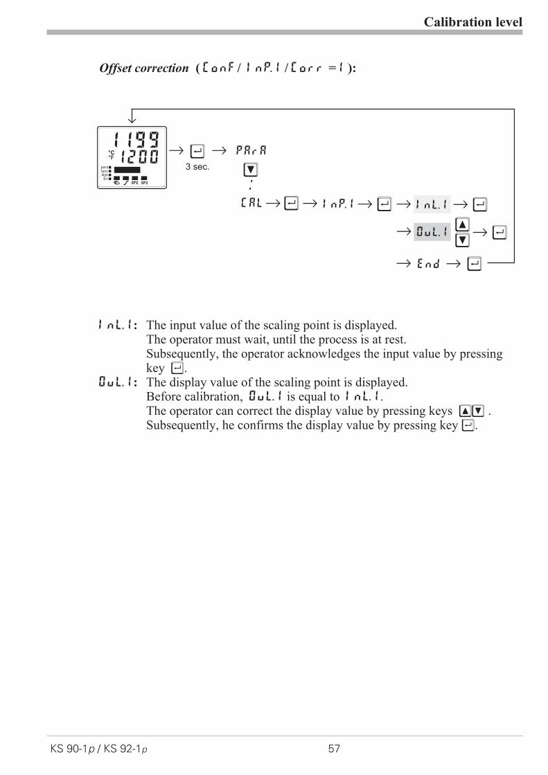
Offset correction ( ConF/ InP.1 / Corr =1 ):
InL.1: The input value of the scaling point is displayed.The operator must wait, until the process is at rest.Subsequently, the operator acknowledges the input value by pressingkey Ù.
OuL.1: The display value of the scaling point is displayed.Before calibration, OuL.1 is equal to InL.1.The operator can correct the display value by pressing keys ÈÌ .Subsequently, he confirms the display value by pressing key Ù.
Calibration level
KS 90-1p / KS 92-1p 57
r
Ì
Ù3 sec.
r PArA
CALrÙr InP.1 Ùr InL.1r r Ù
r
:
OuL.1r r Ù
Endr r Ù
ÌÈ
12001199°C°F
SP.2SP.E
parafuncAda
Err

2-point correction ( ConF/ InP.1 / Corr = 2):
InL.1: The input value of the lower scaling point is displayed.The operator must adjust the lower input value by means of aprocess value simulator and confirm the input value by pressing key Ù.
OuL.1: The display value of the lower scaling point is displayed.Before calibration, OuL.1 equals InL.1.The operator can correct the lower display value by pressing the ÈÌkeys. Subsequently, he confirms the display value by pressing key Ù.
InH.1: The input value of the upper scaling point is displayed. .The operator must adjust the upper input value by means of theprocess value simulator and confirm the input value by pressing key Ù.
OuH.1: The display value of the upper scaling point is displayed.Before calibration OuH.1 equals InH.1.The operator can correct the upper display value by pressing keys ÈÌSubsequently, he confirms the display value by pressing key Ù.
g The parameters (OuL.1, OuH.1) changed at CAL level can be reset by adjustingthe parameters below the lowest adjustment value (OFF) by means of decrementkey Ì .
Calibration level
58 KS 90-1p / KS 92-1p
12001199°C°F
SP.2SP.E
parafuncAda
Err
r
Ì
Ù3 sec.
r PArA
CALrÙr InP.1 Ùr r r Ù
Ù
InL.1
È
InL1
Ù
OuL.1 rÙÌÈ
r ÙInH.1
È
InH.1
Ù
OuH.1 rÙÌÈ
ConFr
Ì
r
ÌÈ
InP.2
InP.3
ÌÈ
End
ÌÈ

7 Programmer level
7.1 Parameter survey
Setting:
w The parameters can be set by means of keys ID
w Transition to the next parameter is by pressing key .
w After the last parameter of a group, donE is displayed and an automatictransition the next group occurs
g Return to the start of a group is by pressing key Ù during 3 sec.
Unless a key is pressed during 30 sec. , the controller returns to processvalue-set-point display ( Timeo Out = 30 sec. )
Programmer level
KS 90-1p / KS 92-1p 59 Parameter survey
Prog Programmer level
ÈÌ Edit
Pro
gram
mer
edit
ing
Copy
Pro
gram
copy
ing
End
prg src
b.lo dst
b.hi
d.00
type
sp
pt
d.out
���
type
sp
pt
tout

7.2 Parameters
Programmer level
Parameters 60 KS 90-1p / KS 92-1p
q ProG
Name Value Range Description Defaultb.Lo 0...9999 Bandwidth lower limit Offb.Hi 0...9999 Bandwidth upper limit Offd.00 Resetvalue of control track 1 ... 4 0
0 track 1= 0; track 2= 0; track 3= 0; track 4= 01 track 1= 1; track 2= 0; track 3= 0; track 4= 02 track 1= 0; track 2= 1; track 3= 0; track 4= 03 track 1= 1; track 2=1; track 3= 0; track 4=04 track 1= 0; track 2= 0; track 3= 1; track 4= 05 track 1= 1; track 2= 0; track 3= 1; track 4= 06 track 1= 0; track 2= 1; track 3= 1; track 4= 07 track 1= 1; track 2= 1; track 3= 1; track 4= 08 track 1= 0; track 2= 0; track 3= 0; track 4= 19 track 1= 1; track 2= 0; track 3= 0; track 4=1
10 track 1= 0; track 2= 1; track 3= 0; track 4= 111 track 1= 1; track 2= 1; track 3= 0; track 4= 112 track 1= 0; track 2= 0; track 3= 1; track 4= 113 track 1= 1; track 2= 0; track 3= 1; track 4= 114 track 1= 0; track 2= 1; track 3= 1; track 4= 115 track 1= 1; track 2= 1; track 3= 1; track 4= 1
tYPE segment type 1 00 time1 gradient2 hold3 step4 time and wait5 gradient and wait6 hold and wait7 step and wait8 end segment
SP -1999...9999 segment end set-point 1Pt 0...9999 segment time/-gradient 1
d.Out control track 1...4 - 1 (see parameterd.00)tYPE segment type 2 (see segment type 1) 0SP -1999...9999 segment end set-point 2Pt 0...9999 segment time/-gradient 2
d.Out control track 1...4 - 2 (see parameterd.00)tYPE segment type3 (see segment type 1) 0SP -1999...9999 segment end set-point3Pt 0...9999 segment time/-gradient 3
d.Out control track 1...4 - 3 (see parameterd.00)tYPE segment type 4 (see segment type 1) 0SP -1999...9999 segment end set-point 4Pt 0...9999 segment time/-gradient 4
d.Out control track 1...4 - 4 (see parameterd.00)
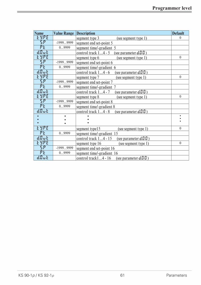
Programmer level
KS 90-1p / KS 92-1p 61 Parameters
Name Value Range Description DefaulttYPE segment type 3 (see segment type 1) 0SP -1999...9999 segment end set-point 5Pt 0...9999 segment time/-gradient 5
d.Out control track 1...4 - 5 (see parameterd.00)tYPE segment type 6 (see segment type 1) 0SP -1999...9999 segment end set-point 6Pt 0...9999 segment time/-gradient 6
d.Out control track 1...4 - 6 (see parameterd.00)tYPE segment type 7 (see segment type 1) 0SP -1999...9999 segment end set-point 7Pt 0...9999 segment time/-gradient 7
d.Out control track 1...4 - 7 (see parameterd.00)tYPE segment type 8 (see segment type 1) 0SP -1999...9999 segment end set-point 8Pt 0...9999 segment time/-gradient 8
d.Out control track 1...4 - 8 (see parameterd.00)www
www
www
www
tYPE segment type15 (see segment type 1) 0Pt 0...9999 segment time/-gradient 15
d.Out control track 1...4 - 15 (see parameterd.00)tYPE segment type 16 (see segment type 1) 0SP -1999...9999 segment end set-point 16Pt 0...9999 segment time/-gradient 16
d.Out control track1...4 - 16 (see parameterd.00)
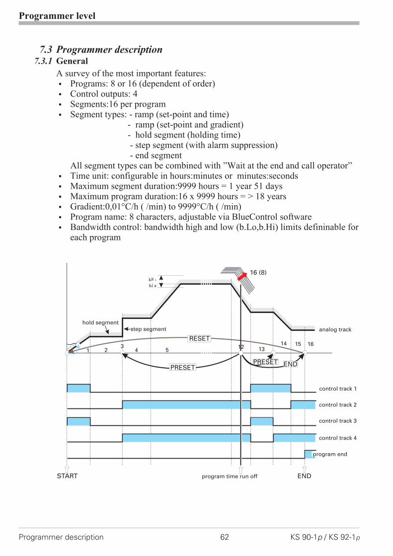
7.3 Programmer description7.3.1 General
A survey of the most important features:
w Programs: 8 or 16 (dependent of order)
w Control outputs: 4
w Segments:16 per program
w Segment types: - ramp (set-point and time)- ramp (set-point and gradient)- hold segment (holding time)- step segment (with alarm suppression)- end segment
All segment types can be combined with ”Wait at the end and call operator”
w Time unit: configurable in hours:minutes or minutes:seconds
w Maximum segment duration:9999 hours = 1 year 51 days
w Maximum program duration:16 x 9999 hours = > 18 years
w Gradient:0,01°C/h ( /min) to 9999°C/h ( /min)
w Program name: 8 characters, adjustable via BlueControl software
w Bandwidth control: bandwidth high and low (b.Lo,b.Hi) limits defininable foreach program
Programmer level
Programmer description 62 KS 90-1p / KS 92-1p
b.Hi
b.Lo
hold segmentstep segment analog track
control track 1
control track 2
control track 3
control track 4
1 2 4 5 12 1314 15
16 (8)
16
PRESET ENDPRESET
RESET
START ENDprogram time run off
3
program end
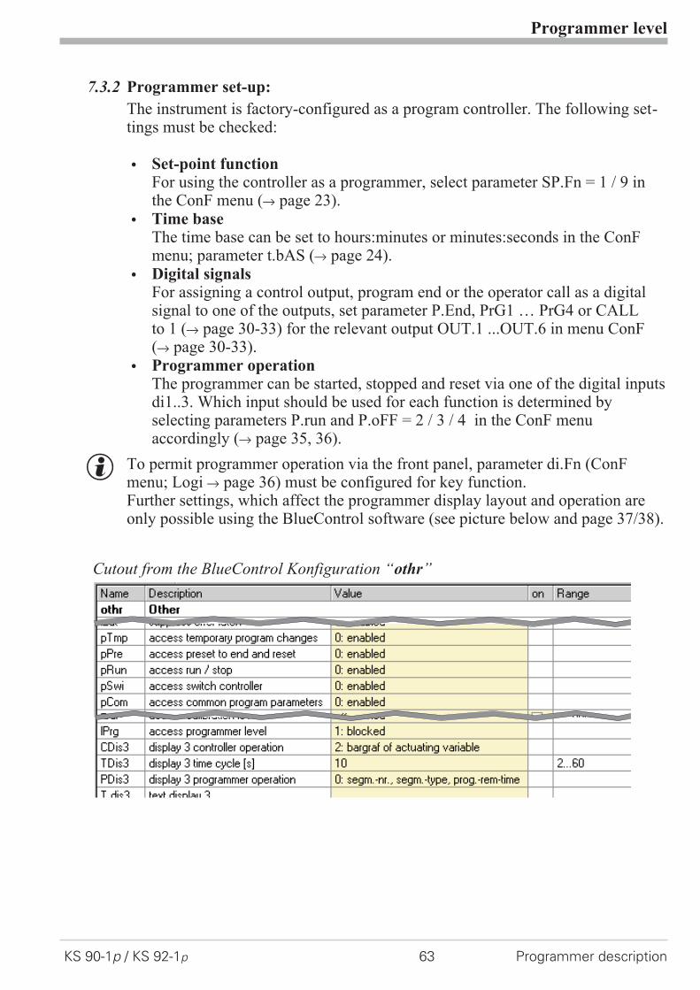
7.3.2 Programmer set-up:
The instrument is factory-configured as a program controller. The following set-tings must be checked:
w Set-point functionFor using the controller as a programmer, select parameter SP.Fn = 1 / 9 inthe ConF menu (r page 23).
w Time baseThe time base can be set to hours:minutes or minutes:seconds in the ConFmenu; parameter t.bAS (r page 24).
w Digital signalsFor assigning a control output, program end or the operator call as a digitalsignal to one of the outputs, set parameter P.End, PrG1 … PrG4 or CALLto 1 (r page 30-33) for the relevant output OUT.1 ...OUT.6 in menu ConF(r page 30-33).
w Programmer operationThe programmer can be started, stopped and reset via one of the digital inputsdi1..3. Which input should be used for each function is determined byselecting parameters P.run and P.oFF = 2 / 3 / 4 in the ConF menuaccordingly (r page 35, 36).
g To permit programmer operation via the front panel, parameter di.Fn (ConFmenu; Logi r page 36) must be configured for key function.Further settings, which affect the programmer display layout and operation areonly possible using the BlueControl software (see picture below and page 37/38).
Programmer level
KS 90-1p / KS 92-1p 63 Programmer description
Cutout from the BlueControl Konfiguration “othr”
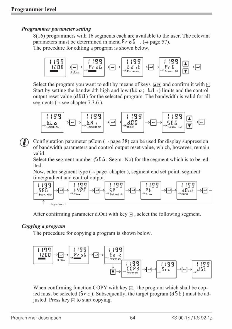
Programmer parameter setting
8(16) programmers with 16 segments each are available to the user. The relevantparameters must be determined in menu ProG . (r page 57).The procedure for editing a program is shown below.
Select the program you want to edit by means of keys ID and confirm it with Ù.Start by setting the bandwidth high and low (b.Lo; b.Hi) limits and the controloutput reset value (d.00) for the selected program. The bandwidth is valid for allsegments (r see chapter 7.3.6 ).
g Configuration parameter pCom (r page 38) can be used for display suppressionof bandwidth parameters and control output reset value, which, however, remainvalid.Select the segment number (SEg; Segm.-No) for the segment which is to be ed-ited.Now, enter segment type (r page chapter ), segment end set-point, segmenttime/gradient and control output.
After confirming parameter d.Out with key Ù , select the following segment.
Copying a program
The procedure for copying a program is shown below.
When confirming function COPY with key Ù, the program which shall be cop-ied must be selected (Src). Subsequently, the target program (dSt) must be ad-justed. Press key Ù to start copying.
Programmer level
Programmer description 64 KS 90-1p / KS 92-1p
ProG1199
paraÙ Ù Ù Ù
3 Sek.
12001199
Edit Prg1199 1199
para para
Program Prog. 01 Ì
Ì
ÙÌ
Ì
Ù1199
paraSEGSegm.-No
Ù Ù1199 1199 1199
para para parab.Lo b.Hi d.00BandLow BandHigh 0000
Ù Ù Ù Ù Ù1199 1199 1199 1199 1199
para para para para para
Time
SEG typE SP Pt d.OutSegm.-No Setpoint Time 0000
Segm.-No + 1
ProG1199
paraÙ Ù
Ù Ù
3 Sek.
12001199
Edit
Src dSt
1199
1199 1199
para
para para
Program
ÌCOpy1199
para
Program
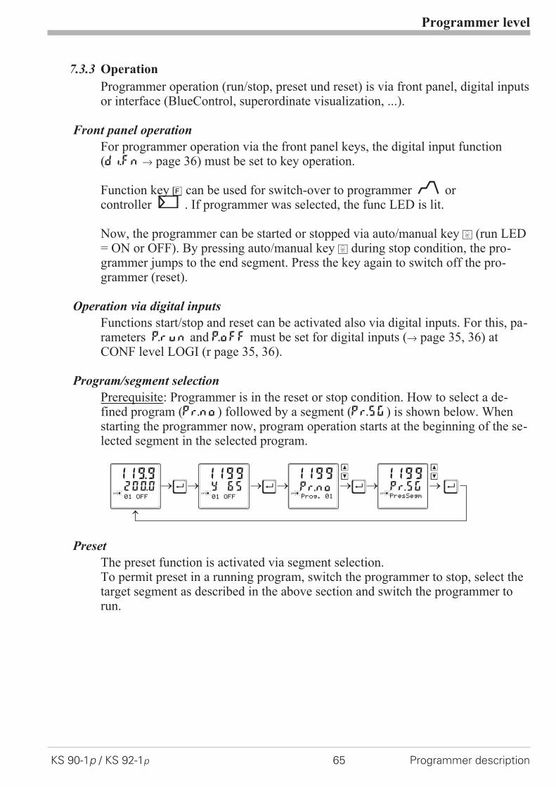
7.3.3 Operation
Programmer operation (run/stop, preset und reset) is via front panel, digital inputsor interface (BlueControl, superordinate visualization, ...).
Front panel operation
For programmer operation via the front panel keys, the digital input function(di.Fn r page 36) must be set to key operation.
Function key è can be used for switch-over to programmer orcontroller . If programmer was selected, the func LED is lit.
Now, the programmer can be started or stopped via auto/manual key H (run LED= ON or OFF). By pressing auto/manual key H during stop condition, the pro-grammer jumps to the end segment. Press the key again to switch off the pro-grammer (reset).
Operation via digital inputs
Functions start/stop and reset can be activated also via digital inputs. For this, pa-rameters P.run and P.oFF must be set for digital inputs (r page 35, 36) atCONF level LOGI (r page 35, 36).
Program/segment selection
Prerequisite: Programmer is in the reset or stop condition. How to select a de-fined program (Pr.no) followed by a segment (Pr.SG) is shown below. Whenstarting the programmer now, program operation starts at the beginning of the se-lected segment in the selected program.
Preset
The preset function is activated via segment selection.To permit preset in a running program, switch the programmer to stop, select thetarget segment as described in the above section and switch the programmer torun.
Programmer level
KS 90-1p / KS 92-1p 65 Programmer description
Ù Ù Ù Ù119.9 1199 1199 1199
para para para para200.0 Y 65 Pr.no Pr.SG01 OFF 01 OFF Prog. 01 PresSegm
Ì Ì
Ì Ì

7.3.4 Programmer display
Programmer is in reset and the internal controller set-pointis effective. Segment or program number and OFF are dis-played (configurable with BlueControl: Configuration r
Other r PDis3).
Programmer running (run LED is lit). Segment or programnumber, segment type (/ rising; \ falling; - hold) and pro-gram/segment rest time or runtime are displayed(configurable with BlueControl: Configuration r Other rPDis3).
Program end was reached. The set-point defined in the lastsegment is effective. Segment or program number and Endare displayed (configurable with BlueControl: Configura-tion r Other r PDis3).
Function key è was used to switch over to the controller.The instantaneously effective correcting variable is dis-played.
Programmer level
Programmer description 66 KS 90-1p / KS 92-1p
SP.2 runSP.E
parafuncAda
Err
01/12:30
SP.2 runSP.E
parafuncAda
Err
01 OFF
SP.2 runSP.E
parafuncAda
Err
16 End
SP.2 runSP.E
parafuncAda
Err
ûûû_____
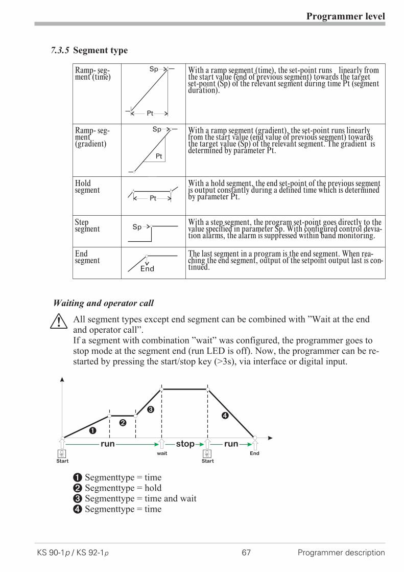
7.3.5 Segment type
Ramp- seg-ment (time)
With a ramp segment (time), the set-point runs linearly fromthe start value (end of previous segment) towards the targetset-point (Sp) of the relevant segment during time Pt (segmentduration).
Ramp- seg-ment(gradient)
With a ramp segment (gradient), the set-point runs linearlyfrom the start value (end value of previous segment) towardsthe target value (Sp) of the relevant segment. The gradient isdetermined by parameter Pt.
Holdsegment
With a hold segment, the end set-point of the previous segmentis output constantly during a defined time which is determinedby parameter Pt.
Stepsegment
With a step segment, the program set-point goes directly to thevalue specified in parameter Sp. With configured control devia-tion alarms, the alarm is suppressed within band monitoring.
Endsegment
The last segment in a program is the end segment. When rea-ching the end segment, output of the setpoint output last is con-tinued.
Waiting and operator call
a All segment types except end segment can be combined with ”Wait at the endand operator call”.If a segment with combination ”wait” was configured, the programmer goes tostop mode at the segment end (run LED is off). Now, the programmer can be re-started by pressing the start/stop key (>3s), via interface or digital input.
1 Segmenttype = time2 Segmenttype = hold3 Segmenttype = time and wait4 Segmenttype = time
Programmer level
KS 90-1p / KS 92-1p 67 Programmer description
Sp
Pt
Sp
Pt
Pt
Sp
End
12
34
Start Start
H Hrun stop run
Endwait

7.3.6 Bandwidth monitoring
Bandwidth monitoring is valid for allprogram segments. An individual band-width can be determined for each pro-gram.When leaving the bandwidth (b.Lo =low limit; b.Hi = high limit), the pro-grammer is stopped (run LED flashes).The program continues running whenthe process value is within the prede-fined bandwidth again.
g With segment type Step and bandwidth monitoring activated, the controldeviation alarm is suppressed, until the process value is in the band again.
g If band alarm signalling as a relay output is required, a control deviation alarmwith the same limits as the band limits must be configured.
7.3.7 Search run at programmer start
The programmer starts the first segment at the actual process value (search run).This may change the effective runtime of the first segment.
7.3.8 Behaviour after mains recovery or sensor error
Mains recovery
After power recovery, the last program set-points and the time elapsed so far arenot available any more. Therefore, the programmer is reset in this case. The con-troller uses the internal set-points and waits for further control commands (therun LED blinks).
Sensor error
With a sensor error, the programmer goes to stop condition (the run LED blinks).After removal of the sensor error, the programmer continues running.
Programmer level
Programmer description 68 KS 90-1p / KS 92-1p
time
process value x
Sp, X
StopStop
set-point profile b.Hi
b.Lo
SP
SP1
Pt (Gradient)1
SP
SP1
Pt1
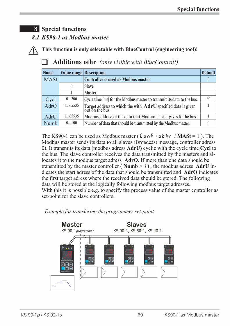
8 Special functions
8.1 KS90-1 as Modbus master
a This function is only selectable with BlueControl (engineering tool)!
The KS90-1 can be used as Modbus master ( ConF / othr / MASt = 1 ). TheModbus master sends its data to all slaves (Broadcast message, controller adress0). It transmits its data (modbus adress AdrU) cyclic with the cycle time Cycl tothe bus. The slave controller receives the data transmitted by the masters and al-locates it to the modbus target adress AdrO. If more than one data should betransmitted by the master controller ( Numb > 1) , the modbus adress AdrU in-dicates the start adress of the data that should be transmitted and AdrO indicatesthe first target adress where the received data should be stored. The followingdata will be stored at the logically following modbus target adresses.With this it is possible e.g. to specify the process value of the master controller asset-point for the slave controllers.
Special functions
KS 90-1p / KS 92-1p 69 KS90-1 as Modbus master
q Additions othr (only visible with BlueControl!)
Name Value range Description Default
MASt Controller is used as Modbus master 0
0 Slave1 Master
Cycl 0...200 Cycle time [ms] for the Modbus master to transmit its data to the bus. 60
AdrO 1...65535 Target address to which the with AdrU specified data is givenout on the bus.
1
AdrU 1...65535 Modbus address of the data that Modbus master gives to the bus. 1
Numb 0...100 Number of data that should be transmitted by the Modbus master. 0
MasterKS 90-1programmer
SlavesKS 90-1, KS 50-1, KS 40-1
KS 40-1 universal
1 2 3 OK
SP.x run
Err
Ada
126125
KS 40-1 universal
1 2 3 OK
SP.x run
Err
Ada
126125
KS 40-1 universal
1 2 3 OK
SP.x run
Err
Ada
126125
KS 40-1 universal
1 2 3 OK
SP.x run
Err
Ada
126125
KS 40-1 universal
1 2 3 OK
SP.x run
Err
Ada
126125
1 2 3 4
F
°C°F
SP.2SP.E
parafuncAda
Err
12001199
KS 90-1 programmer
run
- PrgEdit -
/
02/12:30
Example for transfering the programmer set-point
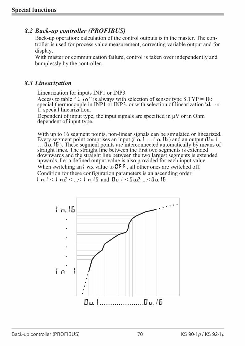
8.2 Back-up controller (PROFIBUS)Back-up operation: calculation of the control outputs is in the master. The con-troller is used for process value measurement, correcting variable output and fordisplay.With master or communication failure, control is taken over independently andbumplessly by the controller.
8.3 Linearization
Linearization for inputs INP1 or INP3Access to table “ Lin” is always with selection of sensor type S.TYP = 18:special thermocouple in INP1 or INP3, or with selection of linearization S.Lin1: special linearization.Dependent of input type, the input signals are specified in µV or in Ohmdependent of input type.
With up to 16 segment points, non-linear signals can be simulated or linearized.Every segment point comprises an input (In.1 … In.16) and an output (Ou.1… Ou.16). These segment points are interconnected automatically by means ofstraight lines. The straight line between the first two segments is extendeddownwards and the straight line between the two largest segments is extendedupwards. I.e. a defined output value is also provided for each input value.When switching an In.x value to OFF, all other ones are switched off.Condition for these configuration parameters is an ascending order.In.1 < In.2 < ...< In.16 and Ou.1 < Ou.2 ...< Ou.16.
Special functions
Back-up controller (PROFIBUS) 70 KS 90-1p / KS 92-1p
In.16
In 1
.
.
.
.
.
.
Ou.1 Ou.16.....................

8.4 Loop alarmThe loop alarm monitors the control loop for interruption(not with three-point stepping controller and not with signallers.)With parameter LP.AL switched to 1(= loop alarm active), an interruption ofthe control loop is detected, unless the process value reacts accordingly withY=100% after elapse of 2xTi.The loop alarm shows that the control loop is interrupted. You should check heat-ing or cooling circuit, sensor, controller and motor actuator.During self-tuning, the control loop is not monitored (loop alarm is not active).
8.5 Heating current input / heating current alarmThe heating current alarm monitors the heating current.In addition to short circuit monitoring, checking either for overload (current >heating current limit value) or for interruption (current < heating current limitvalue) is done.Each of the analog inputs can be used as measurement input.If electrical heating is concerned, INP2 which is always provided can be config-ured for measuring range 0...50mA AC and connected directly using a heatingcurrent transformer.
With t1 < 400 ms or tp < 200 ms (effective time!), heating current monitoringis ineffective.
Special functions
KS 90-1p / KS 92-1p 71 Loop alarm

9 BlueControl
BlueControl is the projection environment for the BluePort� controller series ofPMA. The following 3 versions with graded functionality are available:
The mini version is - free of charge - at your disposal as download at PMAhomepage www.pma-online.de or on the PMA-CD (please ask for).
At the end of the installation the licence number has to be stated or DEMOmode must be chosen. At DEMO mode the licence number can be stated subse-quently under Help r Licence r Change.
BlueControl
72 KS 90-1p / KS 92-1p
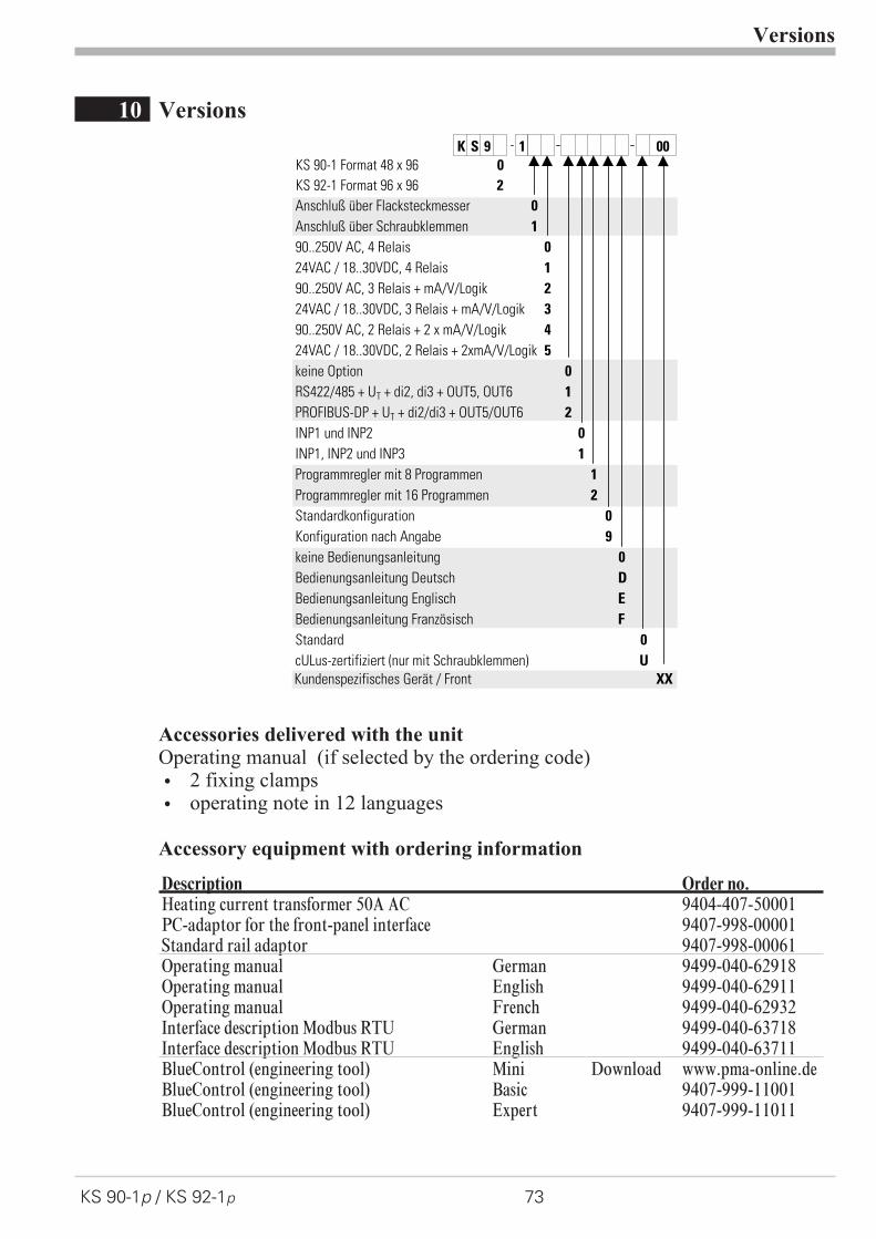
10 Versions
Accessories delivered with the unitOperating manual (if selected by the ordering code)
w 2 fixing clamps
w operating note in 12 languages
Accessory equipment with ordering information
Versions
KS 90-1p / KS 92-1p 73
0
Anschluß über Flacksteckmesser 0
Anschluß über Schraubklemmen 1
90..250V AC, 4 Relais 0
24VAC / 18..30VDC, 4 Relais 1
90..250V AC, 3 Relais + mA/V/Logik 2
24VAC / 18..30VDC, 3 Relais + mA/V/Logik 3
90..250V AC, 2 Relais + 2 x mA/V/Logik 4
24VAC / 18..30VDC, 2 Relais + 2xmA/V/Logik 5
keine Option 0
RS422/485 + UT + di2, di3 + OUT5, OUT6 1
PROFIBUS-DP + UT + di2/di3 + OUT5/OUT6 2
INP1 und INP2 0
INP1, INP2 und INP3 1
Programmregler mit 8 Programmen 1
Programmregler mit 16 Programmen 2
Standardkonfiguration 0
Konfiguration nach Angabe 9
keine Bedienungsanleitung 0
Bedienungsanleitung Deutsch D
Bedienungsanleitung Englisch E
Bedienungsanleitung Französisch F
Standard 0
cULus-zertifiziert (nur mit Schraubklemmen)
Kundenspezifisches Gerät / Front XX
U
K S 9 1 00
KS 92-1 Format 96 x 96 2
KS 90-1 Format 48 x 96
Description Order no.Heating current transformer 50A AC 9404-407-50001PC-adaptor for the front-panel interface 9407-998-00001Standard rail adaptor 9407-998-00061Operating manual German 9499-040-62918Operating manual English 9499-040-62911Operating manual French 9499-040-62932Interface description Modbus RTU German 9499-040-63718Interface description Modbus RTU English 9499-040-63711BlueControl (engineering tool) Mini Download www.pma-online.deBlueControl (engineering tool) Basic 9407-999-11001BlueControl (engineering tool) Expert 9407-999-11011
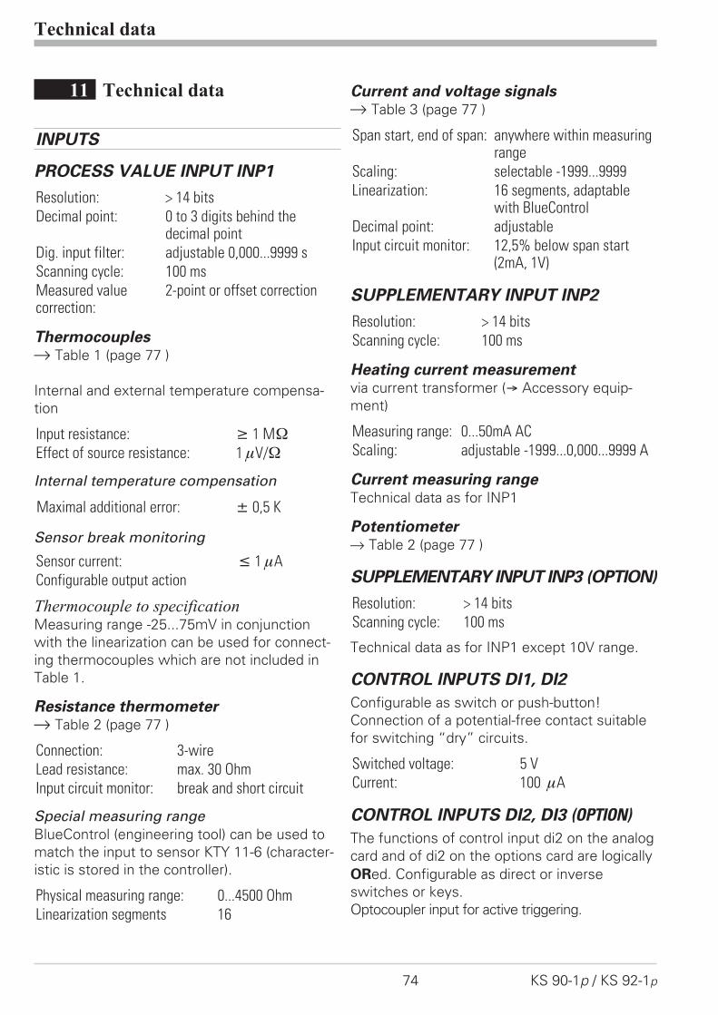
11 Technical data
INPUTS
PROCESS VALUE INPUT INP1
Resolution: > 14 bits
Decimal point: 0 to 3 digits behind thedecimal point
Dig. input filter: adjustable 0,000...9999 s
Scanning cycle: 100 ms
Measured valuecorrection:
2-point or offset correction
Thermocouplesr Table 1 (page 77 )
Internal and external temperature compensa-
tion
Input resistance: 1 M�
Effect of source resistance: 1 V/�
Internal temperature compensation
Maximal additional error: � 0,5 K
Sensor break monitoring
Sensor current: � 1 A
Configurable output action
Thermocouple to specificationMeasuring range -25...75mV in conjunction
with the linearization can be used for connect-
ing thermocouples which are not included in
Table 1.
Resistance thermometerr Table 2 (page 77 )
Connection: 3-wire
Lead resistance: max. 30 Ohm
Input circuit monitor: break and short circuit
Special measuring range
BlueControl (engineering tool) can be used to
match the input to sensor KTY 11-6 (character-
istic is stored in the controller).
Physical measuring range: 0...4500 Ohm
Linearization segments 16
Current and voltage signalsr Table 3 (page 77 )
Span start, end of span: anywhere within measuringrange
Scaling: selectable -1999...9999
Linearization: 16 segments, adaptablewith BlueControl
Decimal point: adjustable
Input circuit monitor: 12,5% below span start(2mA, 1V)
SUPPLEMENTARY INPUT INP2
Resolution: > 14 bits
Scanning cycle: 100 ms
Heating current measurementvia current transformer (� Accessory equip-
ment)
Measuring range: 0...50mA AC
Scaling: adjustable -1999...0,000...9999 A
Current measuring rangeTechnical data as for INP1
Potentiometerr Table 2 (page 77 )
SUPPLEMENTARY INPUT INP3 (OPTION)
Resolution: > 14 bits
Scanning cycle: 100 ms
Technical data as for INP1 except 10V range.
CONTROL INPUTS DI1, DI2
Configurable as switch or push-button!
Connection of a potential-free contact suitable
for switching “dry” circuits.
Switched voltage: 5 V
Current: 100 A
CONTROL INPUTS DI2, DI3 (OPTION)
The functions of control input di2 on the analog
card and of di2 on the options card are logically
ORed. Configurable as direct or inverse
switches or keys.
Optocoupler input for active triggering.
Technical data
74 KS 90-1p / KS 92-1p

Nominal voltage 24 V DC external
Current sink (IEC 1131 type 1)
Logic “0” -3...5 V
Logic “1” 15...30 V
Current requirement approx.. 5 mA
TRANSMITTER SUPPLY UT (OPTION)
Power: 22 mA / � 18 V
As analog outputs OUT3 or OUT4 and trans-
mitter supply UTare connected to different volt-
age potentials, an external galvanic connection
between OUT3/4 and UTis not permissible with
analog outputs.
GALVANIC ISOLATION
Safety isolation
Function isolation
OUTPUTS
RELAY OUTPUTS OUT1...OUT4
Contact type: potential-free changeovercontact
Max.contact rating: 500 VA, 250 V, 2A at 48...62 Hz,resistive load
Min. contact rating: 6V, 1mA DC
Number of electicalswitching cycles:
for I = 1A/2A: ≥ 800.000 /500.000 (at ~ 250V (resistiveload)
Note:
If the relays operate external contactors, these
must be fitted with RC snubber circuits to man-
ufacturer specifications to prevent excessive
switch-off voltage peaks.
OUT3, 4 AS UNIVERSAL OUTPUT
Galvanically isolated from the inputs.
Freely scalable resolution: 11 bits
Current output
0/4...20 mA configurable.
Signal range: 0...approx.22mA
Max. load: � 500 �
Load effect: no effect
Resolution: � 22 �A (0,1%)
Accuracy � 40 �A (0,2%)
Voltage output
0/2...10V configurable
Signal range: 0...11 V
Min. load: ≥ 2 k�
Load effect: no effect
Resolution: �11 mV (0,1%)
Accuracy � 20 mV (0,2%)
OUT3, 4 used as transmitter supply
Output power: 22 mA / � 13 V
OUT3, 4 used as logic output
Load� 500 � 0/� 20 mA
Load > 500 � 0/> 13 V
OUTPUTS OUT5/6 (OPTION)
Galvanically isolated opto-coupler outputs.
Grounded load: common positive voltage.
Output rating: 18...32 VDC; ≤ 70 mA
Internal voltage drop: ≤ 1 V with Imax
Protective circuit: built-in against short circuit,
overload, reversed polarity (free-wheel diode
for relay loads).
POWER SUPPLY
Dependent of order:
AC SUPPLY
Voltage: 90...250 V AC
Frequency: 48...62 Hz
Power consumption approx. 10 VA
Technical data
KS 90-1p / KS 92-1p 75
Process value input INP1Mains supply Supplementary input INP2
Optional input INP3Digital input di1, di2
Relay OUT1 RS422/485 interfaceRelay OUT2 Digital inputs di2, 3Relay OUT3 Universal output OUT3Relay OUT4 Universal output OUT4
Transmitter supply UT
OUT5, OUT6
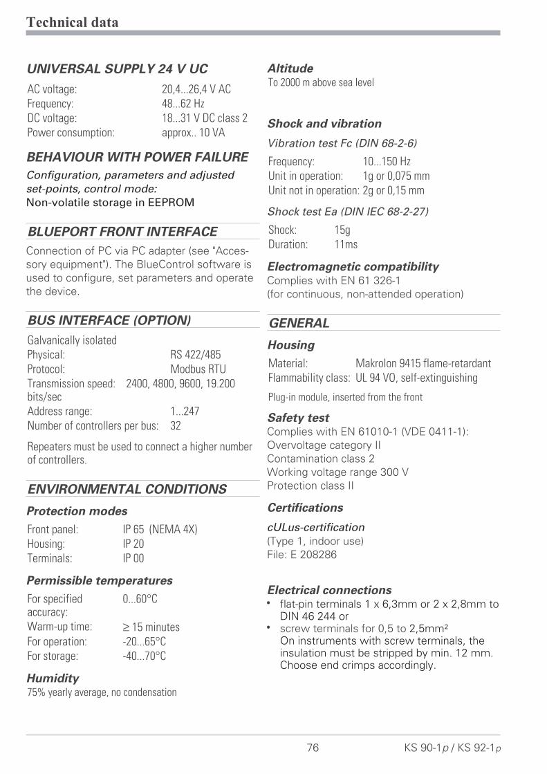
UNIVERSAL SUPPLY 24 V UC
AC voltage: 20,4...26,4 V AC
Frequency: 48...62 Hz
DC voltage: 18...31 V DC class 2
Power consumption: approx.. 10 VA
BEHAVIOUR WITH POWER FAILURE
Configuration, parameters and adjusted
set-points, control mode:
Non-volatile storage in EEPROM
BLUEPORT FRONT INTERFACE
Connection of PC via PC adapter (see "Acces-
sory equipment"). The BlueControl software is
used to configure, set parameters and operate
the device.
BUS INTERFACE (OPTION)
Galvanically isolated
Physical: RS 422/485
Protocol: Modbus RTU
Transmission speed: 2400, 4800, 9600, 19.200bits/sec
Address range: 1...247
Number of controllers per bus: 32
Repeaters must be used to connect a higher numberof controllers.
ENVIRONMENTAL CONDITIONS
Protection modes
Front panel: IP 65 (NEMA 4X)
Housing: IP 20
Terminals: IP 00
Permissible temperatures
For specifiedaccuracy:
0...60°C
Warm-up time: ≥ 15 minutes
For operation: -20...65°C
For storage: -40...70°C
Humidity75% yearly average, no condensation
AltitudeTo 2000 m above sea level
Shock and vibration
Vibration test Fc (DIN 68-2-6)
Frequency: 10...150 Hz
Unit in operation: 1g or 0,075 mm
Unit not in operation: 2g or 0,15 mm
Shock test Ea (DIN IEC 68-2-27)
Shock: 15g
Duration: 11ms
Electromagnetic compatibilityComplies with EN 61 326-1
(for continuous, non-attended operation)
GENERAL
Housing
Material: Makrolon 9415 flame-retardant
Flammability class: UL 94 VO, self-extinguishing
Plug-in module, inserted from the front
Safety testComplies with EN 61010-1 (VDE 0411-1):
Overvoltage category II
Contamination class 2
Working voltage range 300 V
Protection class II
Certifications
cULus-certification
(Type 1, indoor use)
File: E 208286
Electrical connectionsw flat-pin terminals 1 x 6,3mm or 2 x 2,8mm to
DIN 46 244 orw screw terminals for 0,5 to 2,5mm²
On instruments with screw terminals, theinsulation must be stripped by min. 12 mm.Choose end crimps accordingly.
Technical data
76 KS 90-1p / KS 92-1p
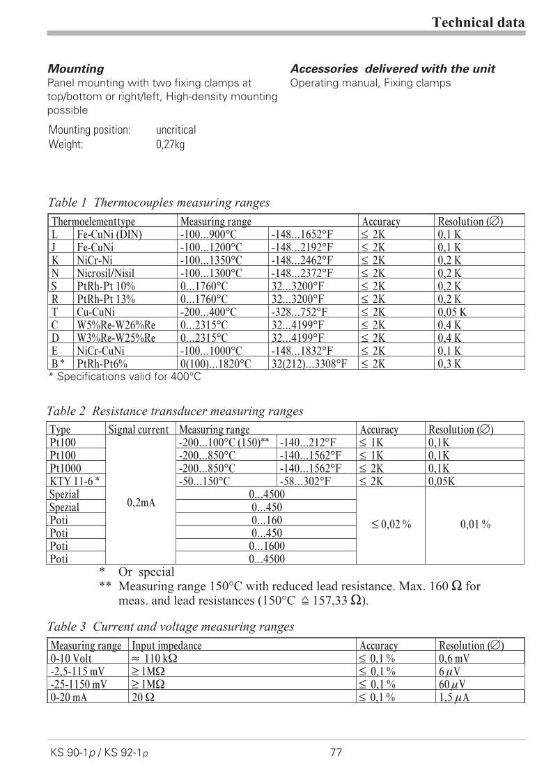
MountingPanel mounting with two fixing clamps at
top/bottom or right/left, High-density mounting
possible
Mounting position: uncritical
Weight: 0,27kg
Accessories delivered with the unitOperating manual, Fixing clamps
Technical data
KS 90-1p / KS 92-1p 77
Measuring range Input impedance Accuracy Resolution (Ô)0-10 Volt ~ 110 k� ß 0,1 % 0,6 mV-2,5-115 mV ? 1M� ß 0,1 % 6 V-25-1150 mV ? 1M� ß 0,1 % 60 V0-20 mA 20 � ß 0,1 % 1,5 A
Table 3 Current and voltage measuring ranges
Type Signal current Measuring range Accuracy Resolution (Ô)Pt100
0,2mA
-200...100°C (150)** -140...212°F ß 1K 0,1KPt100 -200...850°C -140...1562°F ß 1K 0,1KPt1000 -200...850°C -140...1562°F ß 2K 0,1KKTY 11-6 * -50...150°C -58...302°F ß 2K 0,05KSpezial 0...4500
ß 0,02 % 0,01 %
Spezial 0...450Poti 0...160Poti 0...450Poti 0...1600Poti 0...4500
* Or special** Measuring range 150°C with reduced lead resistance. Max. 160 [ for
meas. and lead resistances (150°C = 157,33 [).
Table 2 Resistance transducer measuring ranges
Thermoelementtype Measuring range Accuracy Resolution (Ô)L Fe-CuNi (DIN) -100...900°C -148...1652°F ß 2K 0,1 KJ Fe-CuNi -100...1200°C -148...2192°F ß 2K 0,1 KK NiCr-Ni -100...1350°C -148...2462°F ß 2K 0,2 KN Nicrosil/Nisil -100...1300°C -148...2372°F ß 2K 0,2 KS PtRh-Pt 10% 0...1760°C 32...3200°F ß 2K 0,2 KR PtRh-Pt 13% 0...1760°C 32...3200°F ß 2K 0,2 KT Cu-CuNi -200...400°C -328...752°F ß 2K 0,05 KC W5%Re-W26%Re 0...2315°C 32...4199°F ß 2K 0,4 KD W3%Re-W25%Re 0...2315°C 32...4199°F ß 2K 0,4 KE NiCr-CuNi -100...1000°C -148...1832°F ß 2K 0,1 KB * PtRh-Pt6% 0(100)...1820°C 32(212)...3308°F ß 2K 0,3 K
* Specifications valid for 400°C
Table 1 Thermocouples measuring ranges
12 Safety hints
This unit
– was built and tested in compliance with VDE 0411-1 / EN 61010-1 and deliv-
ered in safe condition.
– complies with European guideline 89/336/EWG (EMC) and is provided with
CE marking.
– was tested before delivery and has passed the tests required by the test sched-
ule. To maintain this condition and to ensure safe operation, the user must fol-
low the hints and warnings given in this operating manual.
– is intended exclusively for use as a measurement and control instrument in
technical installations.
a WarningIf the unit is damaged to an extent that safe operation seems impossible, the unitmust not be taken into operation.
ELECTRICAL CONNECTIONSThe electrical wiring must conform to local standards (e.g. VDE 0100). The inputmeasurement and control leads must be kept separate from signal and power sup-ply leads. In the installation of the controller a switch or a circuit-breaker must beused and signified. The switch or circuit-breaker must be installed near by thecontroller and the user must have easy access to the controller.
COMMISSIONINGBefore instrument switch-on, check that the following information is taken intoaccount:
w Ensure that the supply voltage corresponds to the specifications on the type label.
w All covers required for contact protection must be fitted.
w If the controller is connected with other units in the same signal loop, checkthat the equipment in the output circuit is not affected before switch-on. Ifnecessary, suitable protective measures must be taken.
w The unit may be operated only in installed condition.
w Before and during operation, the temperature restrictions specified forcontroller operation must be met.
SHUT-DOWNFor taking the unit out of operation, disconnect it from all voltage sources andprotect it against accidental operation. If the controller is connected with otherequipment in the same signal loop, check that other equipment in the output cir-cuit is not affected before switch-off. If necessary, suitable protective measuresmust be taken.
Safety hints
78 KS 90-1p / KS 92-1p
MAINTENANCE, REPAIR AND MODIFICATIONThe units do not need particular maintenance.
a WarningWhen opening the units, or when removing covers or components, live parts andterminals may be exposed.
Before starting this work, the unit must be disconnected completely.
After completing this work, re-shut the unit and re-fit all covers and components. Checkif specifications on the type label must be changed and correct them, if necessary.
l CautionWhen opening the units, components which are sensitive to electrostatic dis-charge (ESD) can be exposed. The following work may be done only atworkstations with suitable ESD protection.Modification, maintenance and repair work may be done only by trained and au-thorized personnel. For this purpose, the PMA service should be contacted.
a The cleaning of the front of the controller should be done with a dry or a wetted(spirit, water) handkerchief.
Safety hints
KS 90-1p / KS 92-1p 79

12.1 Resetting to factory settingor to a customer-specific data setIn case of faultyconfiguration, the device can be reset to the default condition.Unless changed, this basic setting is the manufacturer-specific controller defaultsetting. However, this setting may have been changed by means of theBlueControl® software. This is recommendable e.g. when completing commis-sioning in order to cancel accidental alteration easily.Resetting can be activated as follows:
The operator must keep the keys increment and decrement pressed duringpower-on.Then, press key increment to select YES.Confirm factory resetting with Enter and the copy procedure is started(display COPY).Afterwards the device restarts.In all other cases, no reset will occur (timeout abortion).
g If one of the operating levels was blocked and the safety lock is open, reset tofactory setting is not possible.
g If a pass number was defined (via BlueControl® ) and the safety lock is open, butno operating level was blocked, enter the correct pass number when prompted in3. A wrong pass number aborts the reset action.
g The copy procedure ( COPY) can take some seconds.Now, the transmitter is in normal operation.
Safety hints
Resetting to factory setting 80 KS 90-1p / KS 92-1p
ÌÈ + Power on
1
SP.x run
Ada
ErrtorY
FACSP.x run
Ada
Errno
FAC
2
È
SP.x run
Ada
ErrYES
FACSP.x run
Ada
ErrCOPY
FAC
Ù3 4
SP.x run
Ada
Err8.8.8.8.
8.8.8.8.
1. 2.

Index
0-9
2-point correction. . . . . . . . . . . . 56
A
Alarm handling . . . . . . . . . . 25 - 26
B
Bargraph . . . . . . . . . . . . . . . . 11BlueControl. . . . . . . . . . . . . . . 72Bus interface
Technical Data . . . . . . . . . . . 76
C
Calibration level (CAL) . . . . . . 56 - 58Certifications . . . . . . . . . . . . . . 76Configuration examples
2-point controller . . . . . . . . . . 453-point controller . . . . . . . . . . 463-point stepping controller . . . . . 47Continuous controller . . . . . . . . 48D - Y -Off controller . . . . . . . . 49Signaller . . . . . . . . . . . . . . . 44
Configuration levelConfiguration parameters . . . 29 - 41Parameter survey . . . . . . . . . . 28
Connecting diagram . . . . . . . . . . . 6Connecting examples
di2/3, 2-wire transmitter supply . . . 8INP2 current transformer . . . . . . . 7OUT1/2 heating/cooling . . . . . . . 7OUT3 as logic output . . . . . . . . 10OUT3 transmitter supply . . . . . . . 9RS485 interface. . . . . . . . . . . . 9
Control inputs di1, di2, di3Technical data . . . . . . . . . . . . 74
Cooling functionsConstant period . . . . . . . . . . . 43Standard . . . . . . . . . . . . . . . 43
Current signal measuring range . . . . 74
D
Digital inputs di1, di2, di3Configuration . . . . . . . . . . . . 36Technical data . . . . . . . . . . . . 74
E
Environmental conditions . . . . . . . 76Equipment . . . . . . . . . . . . . . . 73
Error list . . . . . . . . . . . . . . . . 13
F
Front view . . . . . . . . . . . . . . . 11
I
Input INP1Configuration . . . . . . . . . . . . 30Parameters. . . . . . . . . . . . . . 54Technical data . . . . . . . . . . . . 74
Input INP2Configuration . . . . . . . . . . . . 31Parameters. . . . . . . . . . . . . . 54Technical data . . . . . . . . . . . . 74
Input INP3Configuration . . . . . . . . . . . . 32Parameters. . . . . . . . . . . . . . 54Technical data . . . . . . . . . . . . 74
Input scaling . . . . . . . . . . . . . . 55
L
LEDAda - LED. . . . . . . . . . . . . . 11Err - LED . . . . . . . . . . . . . . 11func - LED . . . . . . . . . . . . . 11ì - LED. . . . . . . . . . . . . . . 11LED colours . . . . . . . . . . . . . 11ò - LED . . . . . . . . . . . . . . 11para - LED. . . . . . . . . . . . . . 11SP.2 - LED . . . . . . . . . . . . . 11SP.x - LED . . . . . . . . . . . . . 11
Linearization . . . . . . . . . . . . . . 70
M
Maintenance manager . . . . . . . 13 - 14Manual tuning . . . . . . . . . . . . . 23Modbus master . . . . . . . . . . . . . 69Mounting. . . . . . . . . . . . . . . . . 5
O
Offset correction . . . . . . . . . . . . 56Optimization at setpoint . . . . . . . . 18Output OUT1
Configuration . . . . . . . . . . . . 34Technical data . . . . . . . . . . . . 75
Output OUT2Configuration . . . . . . . . . . . . 34Technical data . . . . . . . . . . . . 75
Output OUT3Configuration . . . . . . . . . . . . 35
KS 90-1p / KS 92-1p 81

Technical data . . . . . . . . . . . . 75Output OUT4
Configuration . . . . . . . . . . . . 35Technical data . . . . . . . . . . . . 75
Output OUT5Configuration . . . . . . . . . . . . 36Technical data . . . . . . . . . . . . 75
Output OUT6Configuration . . . . . . . . . . . . 36Technical data . . . . . . . . . . . . 75
P
Parameter setting levelParameter survey . . . . . . . . . . 52Parameters . . . . . . . . . . . 53 - 54
Power supply . . . . . . . . . . . . . . 75
R
Ramp . . . . . . . . . . . . . . . . . . 42Resetting to factory setting . . . . . . . 80Resistance thermometermeasuring range . . . . . . . . . . . . 74
S
Safety hints . . . . . . . . . . . . 78 - 80Safety switch. . . . . . . . . . . . . . . 5Safety test. . . . . . . . . . . . . . . . 76Self-tuning
Cancelation . . . . . . . . . . . . . 21Cancelation causes . . . . . . . . . 21
Setpoint gradient . . . . . . . . . . . . 42Set-point processing . . . . . . . . . . 42
T
Thermocouple measuring range . . . . 74
V
Versions . . . . . . . . . . . . . . . . 73Voltage signal measuring range . . . . 74
82 KS 90-1p / KS 92-1p


Subject to alterations without notice © PMA Prozeß- und Maschinen-Automation GmbHÄnderungen vorbehalten P.O.B. 310 229, D-34058 Kassel, GermanySous réserve de toutes modifications Printed in Germany 9499-040-66111 (08/2013)
9499-040-66111
A5
aufA
6ge
falte
t,2-
fach
gehe
ftet,
SW-D
ruck
Nor
mal
papi
erw
eiß
80g/
m2