Plug-in option FR-A8AX
32
INVERTER Plug-in option INSTRUCTION MANUAL PRE-OPERATION INSTRUCTIONS 1 INSTALLATION 2 CONNECTION DIAGRAM AND TERMINAL 3 PARAMETER 4 FR-A8AX 16-bit digital input function
Transcript of Plug-in option FR-A8AX
INVERTERPlug-in option
INSTRUCTION MANUAL
PRE-OPERATION INSTRUCTIONS 1INSTALLATION 2CONNECTION DIAGRAM AND TERMINAL 3PARAMETER 4
FR-A8AX
16-bit digital input function

Thank you for choosing this Mitsubishi inverter plug-in option.orrect handling might cause an unexpected orrectly.
Instruction Manual and appended a full knowledge of the equipment, safety into "Warning" and "Caution".r severe injury.
or slight injury, or may cause only material
. Both instruction levels must be followed
front cover or the wiring cover removed. Otherwise ck.uld be when performing wiring and periodic
on who is involved in wiring or inspection shall wait ge using a tester or the like. For some time after the
lectric shock.
amage, etc. may occur.
se devices may cause a burn.
2
This Instruction Manual provides handling information and precautions for use of this product. Incfault. Before using this product, always read this Instruction Manual carefully to use this product cPlease forward this Instruction Manual to the end user.
Electric Shock Prevention
Injury Prevention
Safety instructionsDo not attempt to install, operate, maintain or inspect the product until you have read through thisdocuments carefully and can use the equipment correctly. Do not use this product until you haveinformation and instructions. In this Instruction Manual, the safety instruction levels are classified
Incorrect handling may cause hazardous conditions, resulting in death o
Incorrect handling may cause hazardous conditions, resulting in mediumdamage.
The level may even lead to a serious consequence according to conditions
because these are important to personal safety.
Warning While the inverter power is ON, do not open the front cover or the wiring cover. Do not run the inverter with the
you may access the exposed high voltage terminals or the charging part of the circuitry and get an electric sho Do not remove the inverter front cover even if the power supply is disconnected. The only exception for this wo
inspection. You may accidentally touch the charged inverter circuits and get an electric shock. Before wiring or inspection, LED indication of the inverter unit operation panel must be switched OFF. Any pers
for at least 10 minutes after the power supply has been switched OFF and check that there is no residual voltapower-OFF, a high voltage remains in the smoothing capacitor, and it is dangerous.
Any person who is involved in wiring or inspection of this equipment shall be fully competent to do the work. The plug-in option must be installed before wiring. Otherwise you may get an electric shock or be injured. Do not touch the plug-in option or handle the cables with wet hands. Otherwise you may get an electric shock. Do not subject the cables to scratches, excessive stress, heavy loads or pinching. Otherwise you may get an e
Caution The voltage applied to each terminal must be the ones specified in the Instruction Manual. Otherwise a burst, d The cables must be connected to the correct terminals. Otherwise a burst, damage, etc. may occur. The polarity (+ and -) must be correct. Otherwise a burst or damage may occur. While power is ON or for some time after power OFF, do not touch the inverter as it will be extremely hot. Touching the
Warning
Caution
Caution

3
Additional Instructionse unexpected fault, an injury, or an electric
ents or other flammable substance such as oil.uct will be damaged. Halogen-based materials are esidual fumigant components from being infiltrated kaging. Sterilization of disinfection of wooden
machines to make unexpected motions.
e product.
tarting operations. Because all parameters return to
n for explanation. Never operate the inverter in this erating the inverter.
The following instructions must be also followed. If the product is handled incorrectly, it may causshock.
CautionTransportation and mounting Do not install or operate the plug-in option if it is damaged or has parts missing. Do not stand or rest heavy objects on the product. The mounting orientation must be correct. Foreign conductive objects must be prevented from entering the inverter. That includes screws and metal fragm If halogen-based materials (fluorine, chlorine, bromine, iodine, etc.) infiltrate into a Mitsubishi product, the prod
often included in fumigant, which is used to sterilize or disinfest wooden packages. When packaging, prevent rinto Mitsubishi products, or use an alternative sterilization or disinfection method (heat disinfection, etc.) for pacpackage should also be performed before packaging the product.
Trial run Before starting operation, each parameter must be confirmed and adjusted. A failure to do so may cause some
WarningUsage Do not modify the equipment. Do not perform parts removal which is not instructed in this manual. Doing so may lead to fault or damage of th
CautionUsage When parameter clear or all parameter clear is performed, the required parameters must be set again before s
their initial values. Static electricity in your body must be discharged before you touch the product.Maintenance, inspection and parts replacement Do not carry out a megger (insulation resistance) test.Disposal The inverter must be treated as industrial waste.
General instruction Many of the diagrams and drawings in this Instruction Manual show the inverter without a cover or partially ope
manner. The cover must be reinstalled and the instructions in the Instruction Manual must be followed when op

— CONTENTS —6
...................................................6
.........................................................6
...................................................7
...................................................89
...................................................9
...................................................9
.................................................1216
.................................................16
.................................................18
.................................................1920
.................................................20
.................................................21........................................................21.......................................................22.......................................................24
........................................................26
........................................................27.................................................30
4
1 PRE-OPERATION INSTRUCTIONS
1.1 Unpacking and checking the product...........................................1.1.1 Product confirmation..............................................................................
1.2 Component names..........................................................................1.3 Specifications..................................................................................2 INSTALLATION
2.1 Pre-installation instructions ..........................................................2.2 Installation procedure ....................................................................2.3 Wiring...............................................................................................3 CONNECTION DIAGRAM AND TERMINAL
3.1 Connection diagram .......................................................................3.2 Terminals .........................................................................................3.3 Code input example........................................................................4 PARAMETER
4.1 Parameter list ..................................................................................4.2 Setting the parameter .....................................................................
4.2.1 Selection of input method (Pr.304).......................................................4.2.2 Read timing operation selection (Pr.305) ..............................................4.2.3 Bias and gain adjustment (Pr.300 to Pr.303) ........................................4.2.4 Digital input unit selection (Pr.329).......................................................4.2.5 16-bit digital torque command (FR-A800 series only) ..........................
4.3 Precautions .....................................................................................

5
<Notes on descriptions in this Instruction Manual>ogic of the input terminals as sink
Connection diagrams in this Instruction Manual appear with the control llogic, unless otherwise specified.

he product is as you ordered and intact.
to page 9.)
6 PRE-OPERATION INSTRUCTIONS
1 PRE-OPERATION INSTRUCTIONS
1.1 Unpacking and checking the productTake the plug-in option out of the package, check the product name, and confirm that tThis product is a plug-in option dedicated for the FR-A800/F800 series.
1.1.1 Product confirmationCheck the enclosed items.
Plug-in option..................................................1
Mounting screws (M3 8 mm).....................2 (Refer to page 9.)
Spacer....................2 (Refer
ERATION INSTRUCTIONS 7
1Refer to page
stalls spacers. 9
e inverter. 12
e initially-set status ―
9
iew
(a)
(d)
PRE-OP
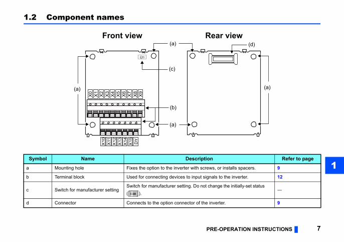
1.2 Component names
Symbol Name Description
a Mounting hole Fixes the option to the inverter with screws, or in
b Terminal block Used for connecting devices to input signals to th
c Switch for manufacturer settingSwitch for manufacturer setting. Do not change th( ).
d Connector Connects to the option connector of the inverter.
(a)
(a)
Front view Rear v
(a)
(b)
(c)
X0
X1
X2
X3
X4
X5
X6
X7
X8
X9
X10
X11
X12
X13
X14
X15 DY

8 PRE-OPERATION INSTRUCTIONS
1.3 Specifications Types of digital input signals3-digit or 4-digit BCD code12-bit or 16-bit binary Selection of digital input signalsOn operation panel or parameter unit Input current5 mA (24 VDC) ... Per circuit Input specificationsRelay contact signal or open collector input Adjustment function • Bias and gain • Analog compensation input (set on operation panel)

INSTALLATION 9
2
er and plug-in option may be damaged.rged before you touch the product.
Spacer
Inverter sideoption connector
le of installation to connector 1
2 INSTALLATION
2.1 Pre-installation instructionsCheck that the inverter's input power and the control circuit power are both OFF.
2.2 Installation procedure
Caution With input power ON, do not install or remove the plug-in option. Otherwise, the invert To avoid damage due to static electricity, static electricity in your body must be discha
(1) Remove the inverter front cover. (Refer to Chapter 2 of the Instruction Manual (Detailed) of the inverter for details on how to remove the front cover.)
(2) For the two mounting holes (as shown in the next page) that will not be tightened with mounting screws, insert spacers.
(3) Fit the connector of the plug-in option to the guide of the connector on the inverter unit side, and insert the plug-in option as far as it goes.
(4) Fit the two locations, the left and right, of the plug-in option securely to the inverter unit by screwing in the supplied mounting screws. (tightening torque 0.33 N·m to 0.40 N·m) If the screw holes do not line up, the connector may not be inserted deep enough. Check the connector.
Spacer
Examp

10 INSTALLATION
Spacer
Spacer
Spacer
Mounting screw
Mounting screw
Mounting screw
Spacer
Spacer
Spacer
Mounting screw
Connector 1Connector 2
Connector 3
Insertion positions for screws and spacers
INSTALLATION 11
2
o not press on the parts on the option re. mounting the plug-in option.s given to option connectors 1, 2 and 3 on .mproper installation, etc., the protective to the mounted position (option connector
ight, then pull it straight out. Pressure
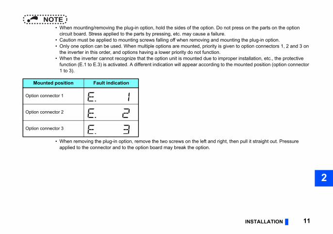
NOTE • When mounting/removing the plug-in option, hold the sides of the option. D
circuit board. Stress applied to the parts by pressing, etc. may cause a failu • Caution must be applied to mounting screws falling off when removing and • Only one option can be used. When multiple options are mounted, priority i
the inverter in this order, and options having a lower priority do not function • When the inverter cannot recognize that the option unit is mounted due to i
function (E.1 to E.3) is activated. A different indication will appear according1 to 3).
• When removing the plug-in option, remove the two screws on the left and rapplied to the connector and to the option board may break the option.
Mounted position Fault indication
Option connector 1
Option connector 2
Option connector 3

a single wire, strip off the sheath of the the terminal.
short circuit may occur with neighboring
o not solder it.
m.f which the crimping is inappropriate, or
n.
tipWires are not insertedinto the sleeve
Unstrandedwires
12 INSTALLATION
2.3 Wiring(1) For the wiring, strip off the sheath of a cable, and use it with a blade terminal. For
wire and apply directly. Insert the blade terminal or the single wire into a socket of
Strip off the sheath for the below length. If the length of the sheath peeled is too long, a wires. If the length is too short, wires might come off.Wire the stripped cable after twisting it to prevent it from becoming loose. In addition, d
Crimp the blade terminal.Insert wires to a blade terminal, and check that the wires come out for about 0 to 0.5 mCheck the condition of the blade terminal after crimping. Do not use a blade terminal othe face is damaged.
Cable sheath stripping length
Caution After wiring, wire offcuts must not be left in the inverter. They may cause a fault, failure or malfunctio
CrumpledDamaged
WireWire
SleeveSleeve
0 to 0.5mm
0 to 0.5mm

INSTALLATION 13
2
Blade terminals commercially available (as of February 2012. The product may be changed without notice.)
hick wire insulation.
nufacturer Crimping tool name
enix Contact Ltd. CRIMPFOX 6
Crimping tool product number
NH 69
A ferrule terminal with an insulation sleeve compatible with the MTW wire which has a t
Cable gauge (mm2)
Ferrule terminal modelMaWith
insulation sleeveWithout
insulation sleeve For UL wire
0.3 AI 0,5-10WH — —
PhoCo.,
0.5 AI 0,5-10WH — AI 0,5-10WH-GB
0.75 AI 0,75-10GY A 0,75-10 AI 0,75-10GY-GB
1 AI 1-10RD A 1-10 AI 1-10RD/1000GB
1.25, 1.5 AI 1,5-10BK A 1,5-10 —
0.75(for two cables) AI-TWIN 2 0,75-10GY — —
Cable gauge (mm2)Blade terminal
product numberInsulation
product number Manufacturer
0.3 to 0.75 BT 0.75-11 VC 0.75 NICHIFU Co.,Ltd.

d screwdriver.
ires without a blade terminal, push the th a flathead screwdriver, and insert the
Flathead screwdriver
pen/close button
rewdriver
14 INSTALLATION
• Wire removalPull the wire while pushing the open/close button all the way down firmly with a flathea
(2) Insert the cable into a socket.When using a single wire or stranded wopen/close button all the way down wiwire.
O
Flathead sc
Open/close button
INSTALLATION 15
2
short circuit with a nearby terminals or
way down may damage the terminal block. If a flathead screwdriver with a narrow tip
changed without notice.)
blade tip slips, it may cause an inverter
n is mounted, take caution not to let the ctromagnetic noises may cause
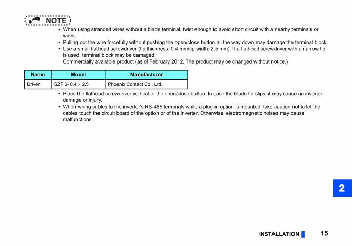
NOTE • When using stranded wires without a blade terminal, twist enough to avoid
wires. • Pulling out the wire forcefully without pushing the open/close button all the • Use a small flathead screwdriver (tip thickness: 0.4 mm/tip width: 2.5 mm).
is used, terminal block may be damaged.Commercially available product (as of February 2012. The product may be
• Place the flathead screwdriver vertical to the open/close button. In case thedamage or injury.
• When wiring cables to the inverter's RS-485 terminals while a plug-in optiocables touch the circuit board of the option or of the inverter. Otherwise, elemalfunctions.
Name Model Manufacturer
Driver SZF 0- 0,4 2,5 Phoenix Contact Co., Ltd.
ollector signal input(sink logic )
X15
DY
FR-A8AX
PC∗1Inverter∗2
18193536
17
5
78
10
12
14
1615
13
11
9
6
4321
X14X13X12X11X10X9X8
X6X5X4X3X2X1X0
X7
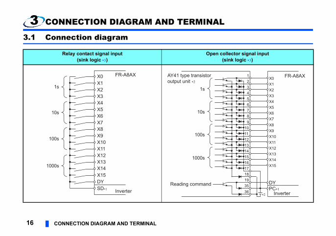
16 CONNECTION DIAGRAM AND TERMINAL
3 CONNECTION DIAGRAM AND TERMINAL
3.1 Connection diagram
Relay contact signal input(sink logic )
Open c
DY
FR-A8AX
InverterSD∗1
X15X14X13X12X11X10X9X8X7X6X5X4X3X2X1X0
1s
10s
100s
1000s
AY41 type transistoroutput unit ∗2
Reading command
1s
10s
100s
1000s
IAGRAM AND TERMINAL 17
3
Use terminal SD or PC on the inverter.
controller. For details on the output module, refer
struction Manual of the inverter for how to switch
or a twin contact for relay contact inputs to
ollector signal:
s
CONNECTION D
AY41 type unit requires 24 VDC power.Example of connection with the output module (AY41 type) of Mitsubishi programmable to the Instruction Manual of the output module manual.
The control logic is the same as that of the inverter.When the logic of the inverter is changed, the option logic also changes. Refer to the Inthe control logic of the inverter.
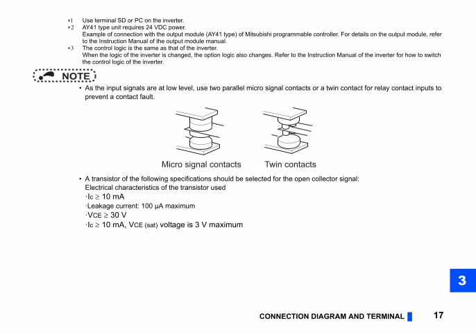
NOTE • As the input signals are at low level, use two parallel micro signal contacts
prevent a contact fault.
• A transistor of the following specifications should be selected for the open cElectrical characteristics of the transistor used·Ic 10 mA·Leakage current: 100 µA maximum·VCE 30 V·Ic 10 mA, VCE (sat) voltage is 3 V maximum
Micro signal contacts Twin contact
Description
equency setting / torque command signal
elay contact or open collector terminal.
ose either BCD code or binary. maximum) or 4-digit (9999 maximum). 1, HFFF maximum) or 16-bit (X0 to X15,
timing signal is necessary. When Pr.305 tion = "1", data is read only while the DY
before the signal is turned OFF is retained (Refer to page 22.)
nd data read timing signals.r.
ink), common terminal (source).ternal power supply common terminal (+) of
ctor output) device, such as a programmable by undesirable current. When the source
is used as a common terminal. Use terminal
18 CONNECTION DIAGRAM AND TERMINAL
3.2 Terminals
Torque command values can be input to the FR-A800 series only.
Terminal location
Terminal symbol
• FR-A8AX
Built-inoptions
X0 to X15
Digital signal input terminal (frterminal ).Input the digital signal at the r(Refer to page 16.)For the digital signal input, choBCD code input is 3-digit (999Binary input is 12-bit (X0 to X1HFFFF maximum).
DY
Data read timing input signal.Use when a digital signal readRead timing operation selecsignal is ON.In addition, the X0 to X15 databy turning OFF the DY signal.
Inverter
SDCommon terminal (sink).Common terminal for digital aUse terminal SD of the inverte
PC
External transistor common (sConnect this terminal to the exa transistor output (open collecontroller, to avoid malfunctionlogic is selected, this terminal PC of the inverter.
X0X1X2X3X4X5X6X7X8X9
X10X11X12X13X14X15DY

IAGRAM AND TERMINAL 19
3
ode input and binary input.
lue greater than 9 is input, it becomes
le selection = any of "0 to 4", X12 to X15
hen the input value is HAB65)input s
Input value(hexadecimal)
Input value(decimal)
5
43877
6
B
A
CONNECTION D
3.3 Code input exampleThe following table explains examples of terminal status and input value during BCD c
NOTE • For BCD code input, the input value of each digit is from 0 to 9. When a va
invalid and the last value is retained. • When Pr.304 Digital input and analog input compensation enable/disab
become disabled.
BCD code input (when the input value is 6325) Binary input (w
Digit Terminal name
Terminal input status Input value Terminal
nameTerminal
statu
1
X0 ON
5
X0 ONX1 OFF X1 OFFX2 ON X2 ONX3 OFF X3 OFF
10
X4 OFF
2
X4 OFFX5 ON X5 ONX6 OFF X6 ONX7 OFF X7 OFF
100
X8 ON
3
X8 ONX9 ON X9 ONX10 OFF X10 OFFX11 OFF X11 ON
1000
X12 OFF
6
X12 OFFX13 ON X13 ONX14 ON X14 OFFX15 OFF X15 ON
is set in Pr.304, digital input is enabled.
he parameter setting value, stop the operation.
inimumsetting crements
Initial value Refer to page
1 Hz 0 Hz 251 Hz 60 Hz/50 Hz 251 Hz 0 Hz 251 Hz 60 Hz/50 Hz 25
9999 21, 27
0 221 260 27150% 270 27
20 PARAMETER
4 PARAMETER
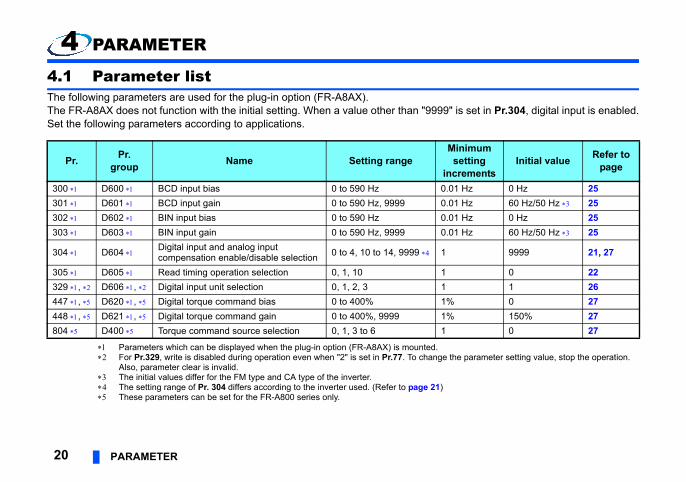
4.1 Parameter listThe following parameters are used for the plug-in option (FR-A8AX).The FR-A8AX does not function with the initial setting. When a value other than "9999"Set the following parameters according to applications.
Parameters which can be displayed when the plug-in option (FR-A8AX) is mounted. For Pr.329, write is disabled during operation even when "2" is set in Pr.77. To change t
Also, parameter clear is invalid. The initial values differ for the FM type and CA type of the inverter. The setting range of Pr. 304 differs according to the inverter used. (Refer to page 21) These parameters can be set for the FR-A800 series only.
Pr. Pr.group Name Setting range
M
in300 D600 BCD input bias 0 to 590 Hz 0.0301 D601 BCD input gain 0 to 590 Hz, 9999 0.0302 D602 BIN input bias 0 to 590 Hz 0.0303 D603 BIN input gain 0 to 590 Hz, 9999 0.0
304 D604 Digital input and analog input compensation enable/disable selection 0 to 4, 10 to 14, 9999 1
305 D605 Read timing operation selection 0, 1, 10 1329 , D606 , Digital input unit selection 0, 1, 2, 3 1447 , D620 , Digital torque command bias 0 to 400% 1%448 , D621 , Digital torque command gain 0 to 400%, 9999 1%804 D400 Torque command source selection 0, 1, 3 to 6 1

PARAMETER 214
input, the input data is taken in decimal.
) of the inverter for the details of terminal 1.command value input, refer to page 27.
Availability of analog input compensation
(: Enabled, : Disabled)
—
—
NOTE • For binary input, the input data is taken in hexadecimal, and for BCD code
4.2 Setting the parameter4.2.1 Selection of input method (Pr.304)
Use terminal 1 for analog input compensation. Refer to the Instruction Manual (Detailed These parameters can be set for the FR-A800 series only. For the details of the torque
Pr.304 setting BCD code input Binary input
0 3 digits —
1 — 12 bits
2 3 digits —
3 — 12 bits
4 — 12 bits. Torque command value input.
10 4 digits —
11 — 16 bits
12 4 digits —
13 — 16 bits
14 — 16 bits. Torque command value input.
9999 (Initial value) No function
entiometer with the FR-A8AX installed, the de input and the compensation input from
otentiometer input or automatic operation n.
minals (X0 to X15) is always imported
minals (X0 to X15) is imported only ted when the DY signal is OFF. ges, the set frequency data before the
minals (X0 to X15) is always imported
uisition.
ON
ON
ON
22 PARAMETER
NOTE • Signals X12 to X15 become invalid when 0 to 4 are set in Pr.304. • Refer to page 19 for a BCD code/binary input example. • If 0 to 5 V (0 to 10 V) is input at the inverter terminal 1 from the external pot
inverter operates at the frequency obtained by adding the FR-A8AX BCD coterminal 1 only when "2, 3, 12, 13" is set in Pr.304.For example, when switching the inputs to perform manual operation with pwith BCD code input, set the BCD code input to "0" under manual operatio
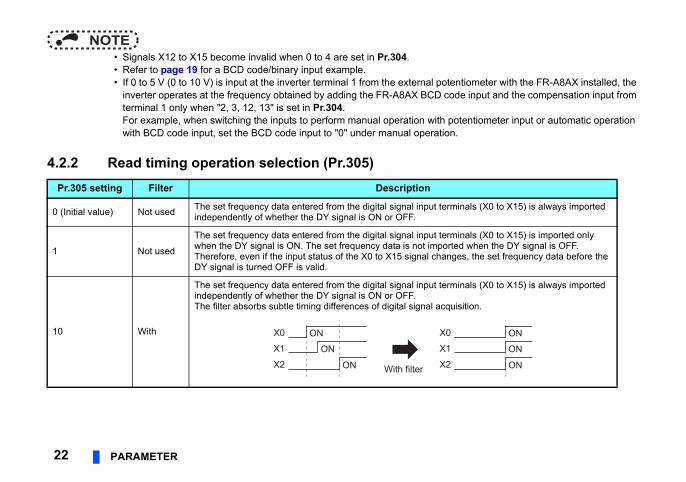
4.2.2 Read timing operation selection (Pr.305)Pr.305 setting Filter Description
0 (Initial value) Not used The set frequency data entered from the digital signal input terindependently of whether the DY signal is ON or OFF.
1 Not used
The set frequency data entered from the digital signal input terwhen the DY signal is ON. The set frequency data is not imporTherefore, even if the input status of the X0 to X15 signal chanDY signal is turned OFF is valid.
10 With
The set frequency data entered from the digital signal input terindependently of whether the DY signal is ON or OFF.The filter absorbs subtle timing differences of digital signal acq
ON
ON
ON With filter
X0
X1
X2
X0
X1
X2
PARAMETER 234
When "0 or 10" is set in Pr.305
en the inverter is turned ON in terminal DY
old the digital signal input (X0 to5) status for 20ms or more.anging the signal within 20ms
ay not reflect it on the set frequency.
How to use the DY signal (when "1" is set in Pr.305)
NOTE • When Pr.305 = "1", all terminals from X0 to X15 are recognized as OFF wh
OFF status.
Digital signal input(terminal X0 to X15)
20ms or more necessary∗
Filter (Pr. 305 = "10")
Reflected on the set frequency
Set frequency
20ms maximum
∗ H X1 Ch m
ON
Digital signal input(terminal X0 to X15)
1ms or more1ms or more
Data read timing signal(terminal DY) OFF
20ms or more necessary
ON
ingt value is set as the output frequency.)
not be made.
e Initial value
0 Hz
60 Hz/50 Hz
0 Hz
60 Hz/50 Hz
al (BCD)
24 PARAMETER
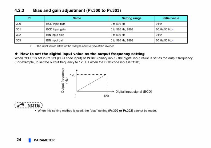
4.2.3 Bias and gain adjustment (Pr.300 to Pr.303)
The initial values differ for the FM type and CA type of the inverter.
How to set the digital input value as the output frequency settWhen "9999" is set in Pr.301 (BCD code input) or Pr.303 (binary input), the digital inpu(For example, to set the output frequency to 120 Hz when the BCD code input is "120"
NOTE • When this setting method is used, the "bias" setting (Pr.300 or Pr.302) can
Pr. Name Setting rang
300 BCD input bias 0 to 590 Hz
301 BCD input gain 0 to 590 Hz, 9999
302 BIN input bias 0 to 590 Hz
303 BIN input gain 0 to 590 Hz, 9999
120
Digital input sign0 120
Out
put f
requ
ency
(Hz)

PARAMETER 254
Bias/gain adjustment for digital inputs
nal.e input), or "HFFF" or "HFFFF" (binary
CD)
inary) Pr.304
Pr.304 =“0, 2(10, 12)”
=“1, 3(11, 13)”
Bias adjustmentBias adjustments can be made for the digital input signal.Set the set frequency at the digital input signal of 0.For BCD code input, set using Pr.300, and for binary input, set using Pr.302.
Gain adjustmentMaximum output frequency (gain) adjustment can be made for the digital input sigSet the output frequency when the digital input signal is "999" or "9999" (BCD codinput).For BCD code input, set using Pr.301, and for binary input, set using Pr.303.
Pr.301Pr.303
Pr.300Pr.302 Bias
Gain
Out
put f
requ
ency
(Hz)
0
0
999(9999)
HFFF(HFFFF)
Digital input signal (B
Digital input signal (B

gital input signal is set as the output
s invalid.
Initial value
1
equencies16 bits
BCD code Binary0 to 99990 Hz 0 to 655350 Hz0 to 9999 Hz 0 to 65535 Hz0 to 999.9 Hz 0 to 6553.5 Hz0 to 99.99 Hz 0 to 655.35 Hz
26 PARAMETER
4.2.4 Digital input unit selection (Pr.329)
When "9999" is set in Pr.301 or Pr.303, it is possible to set the increments when the difrequency. (Refer to page 24.)Frequency = digital input signal value Pr.329 input increments
These are not the inverter maximum output frequencies.
<Example> • Pr.329 = "0"BCD code = 1111110 Hz, binary = H100 (256 in decimal)2560 Hz • Pr.329 = "1"BCD code = 111111 Hz, binary = H100 (256 in decimal)256 Hz • Pr.329 = "2"BCD code = 11111.1 Hz, binary = H100 (256 in decimal)25.6 Hz • Pr.329 = "3"BCD code = 1111.11 Hz, binary = H100 (256 in decimal)2.56 Hz
NOTE • When values other than "9999" are set in Pr.301 or Pr.303, Pr.329 become
Pr. Name Setting range
329 Digital input unit selection 0, 1, 2, 3
Pr.329 setting Input value increments
Available fr12 bits
BCD code Binary0 10 0 to 9990 Hz 0 to 40950 Hz1 (Initial value) 1 0 to 999 Hz 0 to 4095 Hz2 0.1 0 to 99.9 Hz 0 to 409.5 Hz3 0.01 0 to 9.99 Hz 0 to 40.95 Hz

PARAMETER 274
s set in Pr.304 and "4" is set in Pr.804.
Setting range Initial value
to 4, 10 to 14, 9999 9999
to 400% 0
to 400%, 9999 150%
1, 3 to 6 0
Remarks
the Instruction Manual of the inverter for the
the Instruction Manual of FR-A8NC/FR-FR-A8NP for details.
" is set in Pr.304
4" is set in Pr.304
the Instruction Manual of FR-A8NC/FR-FR-A8NP for details.
4.2.5 16-bit digital torque command (FR-A800 series only)
Digital torque command can be given under torque control using the FR-A8AX.A digital command can be given using the FR-A8AX when "4 (12-bit)" or "14 (16-bit)" i
Pr. Name
304 Digital input and analog input compensation enable/disable selection 0
447 Digital torque command bias 0
448 Digital torque command gain 0
804 Torque command source selection 0,
Pr.804 setting Description
0 Torque command by terminal 1 analog inputRefer todetails.1 Torque command by parameter setting
Setting value of Pr.805 or Pr.806 (-400% to 400%)
3Torque command via CC-Link communication (FR-A8NC/FR-A8NCE)Torque command via PROFIBUS-DP communication (FR-A8NP)
Refer toA8NCE/
412-bit digital input (FR-A8AX) When "4
16-bit digital input (FR-A8AX) When "1
5 Torque command via CC-Link communication (FR-A8NC/FR-A8NCE)Torque command via PROFIBUS-DP communication (FR-A8NP)
Refer toA8NCE/6
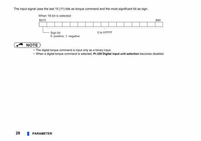
The input signal uses the last 15 (11) bits as torque command and the most significant bit as sign.
ction becomes disabled.
Bit0
28 PARAMETER
NOTE • The digital torque command is input only as a binary input. • When a digital torque command is selected, Pr.329 Digital input unit sele
Bit15
0 to H7FFFSign bit0: positive, 1: negative
When 16-bit is selected

PARAMETER 294
Input method of torque command
value.s shown below.t 400%.
command value
Digital input signalPr.4470 H7FFF
(H7FF)
Most significant bit = 0-150%
Initial value
Digital input signalH7FFF(H7FF)
Torque command may be input in either of the following two ways: Set the torque commands at 0 and
H7FFF (H7FF) signal inputsSet the torque command value when the input signal is "0" in Pr.447 and the torque command value when the input signal is "H7FFF (H7FF) in Pr.448.The figure on the right shows the case when the torque command value is set using input signal H7FFF (H7FF) when the torque command value is 150% (initial value of Pr.448). When the most significant bit of input signal is positive, a negative torque command value (-150%) is also set at the same time. Use the digital input value as the
torque commandWhen "9999" is set in Pr.448, the input signal is considered as a torque commandFor example, the torque command value when the input signal is H190 is 400%, aEven if a value higher than H190 is input, the torque command value is clamped a
Torque
Pr.448
H7FFF(H7FF)
Most significant bit = 1
150%
Torque command value
400%
0
Most significant bit = 0Most significant bit = 1
H7FFF(H7FF) H190
H190
-400%

time is the period of time required to
ration is performed with the inputs
set frequency becomes 0 Hz.
) > AU (terminal 4) > Pulse train input >
30 PARAMETER
4.3 Precautions • Acceleration/deceleration time
When the frequency is set with the digital input signal, the acceleration/decelerationreach Pr.20 Acceleration/deceleration reference frequency.
• The following restrictions are applied on the digital input signal:When one of H0A to H0F is input to each digit while BCD code input is set, the opeprevious to H0A to H0F. H0A to H0F inputs are ignored.If binary input is changed to BCD code input while H0A to H0F are being input, the
• The priorities of the frequency setting are as follows:JOG > Stop-on contact (RT, RL) > Multi-speed command (RH, RM, RL) > PID (X14Digital command by the FR-A8AX > terminal 2
When digital input is valid, terminal 2 is invalid.
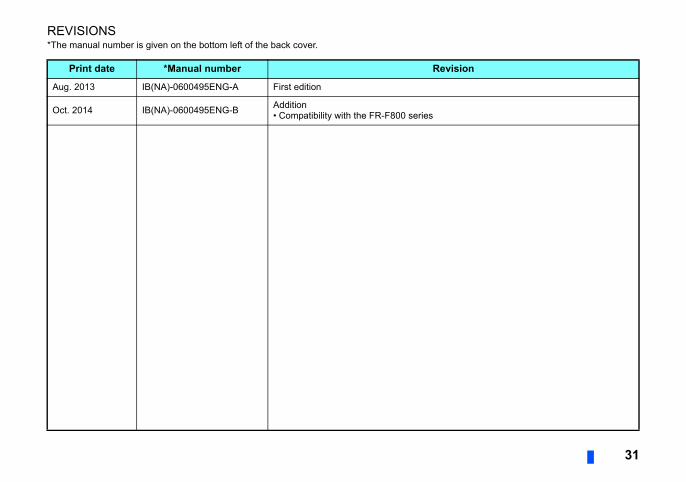
31
REVISIONS*The manual number is given on the bottom left of the back cover.
Print date *Manual number Revision
Aug. 2013 IB(NA)-0600495ENG-A First edition
Oct. 2014 IB(NA)-0600495ENG-B Addition• Compatibility with the FR-F800 series

INVERTER
HEAD OFFICE: TOKYO BUILDING 2-7-3, MARUNOUCHI, CHIYODA-KU, TOKYO 100-8310, JAPAN
IB(NA)-0600495ENG-B(1410) MEE Printed in Japan Specifications subject to change without notice.