Plot 1 Huntters inn calc Pack
45
Structural Solutions Management Ltd The Chapel House, 11a Alexandra Park, Redland, Bristol, BS6 6QB tel: 0117 924 5014 fax: 0117 924 5207 The Warren, Main Street, Keevil, Wiltshire, BA14 6ND tel: 01380 871410 fax: 01380 871630 Email: [email protected] Website: www.structuralsolutions.co.uk 21 August 2011 Job No: 5152SHM30 Structural Calculations Hunter's Inn PH , Southampton Road, Ringwood, Hampshire Plot 1.
-
Upload
rob-douglas -
Category
Documents
-
view
218 -
download
0
description
calc Pack for timber frame
Transcript of Plot 1 Huntters inn calc Pack
Structural Solutions Management Ltd The Chapel House, 11a Alexandra Park, Redland, Bristol, BS6 6QB tel: 0117 924 5014 fax: 0117 924 5207 The Warren, Main Street, Keevil, Wiltshire, BA14 6ND tel: 01380 871410 fax: 01380 871630 Email: [email protected] Website: www.structuralsolutions.co.uk
21 August 2011 Job No: 5152SHM30
Structural Calculations
Hunter's Inn PH , Southampton Road, Ringwood, Hampshire Plot 1.

Project
Hunter's Inn PH , Southampton Road, Ringwood Sheet no./rev.
5152SHM30
Introduction and Assumptions By/Date
RD / 21/08/11
Checked by Structural Solutions
Tel: 0117 924 5014
1.1. Client: Scandia-Hus Manufacturing. Brewhurst Sawmill,
Roundstreet Common Billingshurst West Sussex PO18 0DB
Our ref: 5152SHM30
1.2. 1. Roof Cut Softwood rafters and purlins with proprietary trusses – Fully sarked with 9 mm OSB.
Comments: Refer to structural sketch for details.
2. Beams and Lintels
Comments: Refer to structural sketch for details.
3. Racking a) Overall racking strength adequate in the both directions b) 66% of required racking strength achieved with sheathing in both directions
Comments: Refer to structural sketch for details
.
5. Loadbearing Walls
Additional studs at concentrated loads
Comments: Refer to structural sketch for details.
Project
Hunter's Inn PH , Southampton Road, Ringwood Sheet no./rev.
5152SHM30
Introduction and Assumptions By/Date
RD / 21/08/11
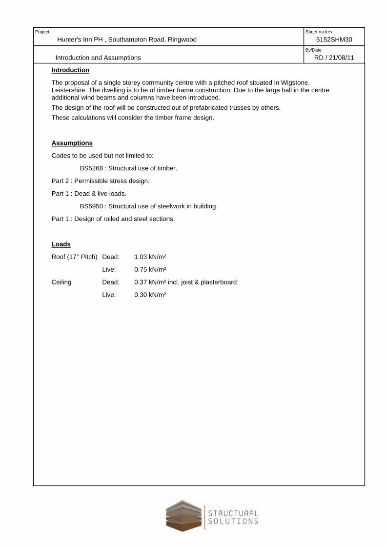
Introduction
The proposal of a single storey community centre with a pitched roof situated in Wigstone, Leistershire. The dwelling is to be of timber frame construction. Due to the large hall in the centre additional wind beams and columns have been introduced. The design of the roof will be constructed out of prefabricated trusses by others. These calculations will consider the timber frame design.
Assumptions
Codes to be used but not limited to:
BS5268 : Structural use of timber.
Part 2 : Permissible stress design.
Part 1 : Dead & live loads.
BS5950 : Structural use of steelwork in building.
Part 1 : Design of rolled and steel sections.
Loads
Roof (17° Pitch) Dead: 1.03 kN/m²
Live: 0.75 kN/m²
Ceiling Dead: 0.37 kN/m² incl. joist & plasterboard
Live: 0.30 kN/m²

Project
Hunter's Inn PH , Southampton Road, Ringwood Sheet no./rev.
5152SHM30
Introduction and Assumptions By/Date
RD/ 20/08/2011
Introduction
The proposed structures are two storey timber frame dwellings in Ringwood, Hampshire. The timber frame structure will be fixed to a concrete foundation designed by others and these calculations cover the elements above ground floor level only.
The roof structure will be fully sarked. It is to be constructed from softwood , with traditional insulation, spanning between timber beams and external walls. The external walls are to be constructed of timber frame with timber cladding. Internal walls are of traditional timber frame panels and the floor of engineered floor joists of specialist design spanning between the walls..
Assumptions
The site is in a country location.
Codes to be used include but not limited to:
BS5268 structural use of timber.
Part 2 : Permissible stress design
Part 6 : Timber frame walls
BS6399 : Loading for Buildings
Part 1 : Dead & live loads
BS5950 Structural use of steelwork in building
Part 1: Code of practice for design
==
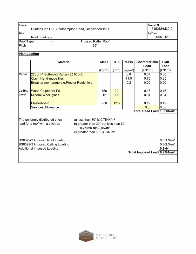
a) less than 30° is 0.75kN/m²
c) greater than 60° is 0kN/m²
Additional Imposed LoadingTotal Imposed Load
b) greater than 30° but less than 60° 0.75[(60-α)/30]kN/m²
0.93kN/m²
BS6399-3 Imposed Roof Loading 0.63kN/m²
The uniformly distributed snow load for a roof with a pitch of:
0.30kN/m²BS6399-3 Imposed Ceiling Loading0.9kN
0.04
0.120.30
0.700.00
0.850.00
Plan Load
(kN/m²)
0.16
0.08(kN/m²)
0.07
1.55kN/m²Total Dead Load
Mass THK Mass
0.1212.5
0.16
Characteristic Load
Services Allowance
0.04
0.3Plasterboard 950
300
35°
Plan Loading
Material
220 x 44 Softwood Rafters @ 600c/cRafter(mm) (kg/m²)
6.8
Project
By/DateTitle20/07/2011
5152SHM30(2)Project No.
Roof TypePitch
Ceiling Level
(kg/m³)
Clay - Hand-made tilesBreather membrane e.g.Proctor Roofshield
Wood Chipboard P5Mineral Wool, glass 12
71.00.2
750 22
Hunter's Inn PH , Southampton Road, Ringwood\Plot 1
Roof LoadingsTrussed Rafter Roof
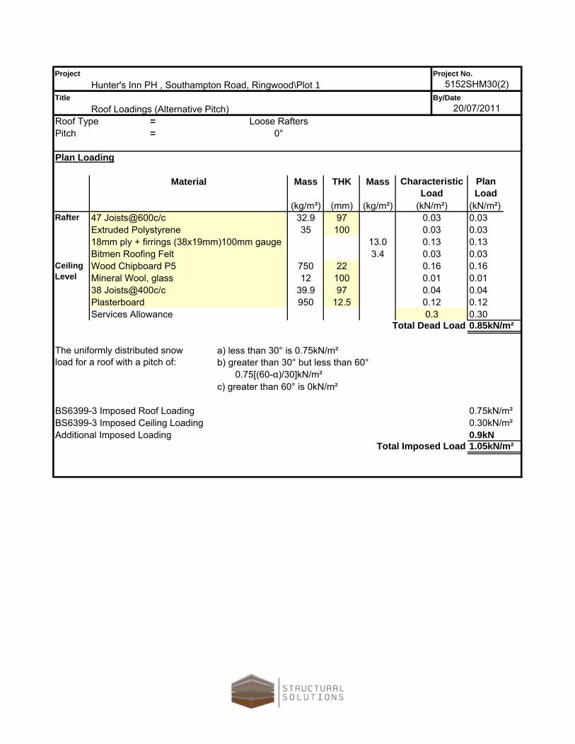
==
a) less than 30° is 0.75kN/m²
c) greater than 60° is 0kN/m²
Additional Imposed LoadingTotal Imposed Load
32.9 9735 100
ProjectHunter's Inn PH , Southampton Road, Ringwood\Plot 1
Project No.5152SHM30(2)
TitleRoof Loadings (Alternative Pitch)
By/Date20/07/2011
Roof Type Loose RaftersPitch 0°
Plan Loading
Material Mass THK Mass Characteristic Load
Plan Load
(kg/m³) (mm) (kg/m²) (kN/m²) (kN/m²)
0.130.03
0.16 0.16
Rafter
18mm ply + firrings (38x19mm)100mm gauge 13.0 0.13Bitmen Roofing Felt 3.4 0.03
47 Joists@600c/c 0.03 0.03Extruded Polystyrene 0.03 0.03
0.01 0.01Ceiling Level
Wood Chipboard P5 750 22Mineral Wool, glass 12 10038 Joists@400c/c 39.9 97 0.04 0.04
0.12Services Allowance 0.3 0.30Plasterboard 950 12.5 0.12
Total Dead Load 0.85kN/m²
The uniformly distributed snow load for a roof with a pitch of: b) greater than 30° but less than 60°
0.75[(60-α)/30]kN/m²
BS6399-3 Imposed Roof Loading 0.75kN/m²BS6399-3 Imposed Ceiling Loading 0.30kN/m²
0.9kN1.05kN/m²

(kN/m²)
Partition LoadingTotal Dead Load kN/m²
BS6399-1 Imposed Loading kN/m²
kN/m²
Project No.5152SHM30(2)
Load
20/07/2011Floor Loadings
Hunter's Inn PH , Southampton Road, Ringwood\Plot 1Project
Title By/Date
Floor Const.
Plan Loading
THK Mass(kg/m³) (mm) (kg/m²)
Wood Chipboard P5 0.15220 FJI - 45 Joists @ 400c/c 0.01
7507.4
20125
Plasterboard 950
Mineral wool - as resilient layer 0.10100 100
*Communal areas can be designed for 1.5 kN/sq.m imposed load in accordance with Note 1, Table 1 of BS 6399 - 1:1996 if the building does not exceed three storeys and not more than four flats per floor level are accessible from one staircase.
0.400.96
1.50
0.19
1.50
0.11
BS6399-1 Imposed Loading for Corridors
BG MF Hangers @ 600c/c 212
MassMaterial
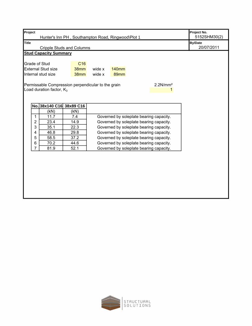
Grade of StudExternal Stud size
No.
1234567
Project No.5152SHM30(2)
ProjectHunter's Inn PH , Southampton Road, Ringwood\Plot 1
TitleCripple Studs and Columns
By/Date20/07/2011
38x89 C16
Load duration factor, K3
2.2N/mm²1
(kN)38x140 C16
(kN)
Permissable Compression perpendicular to the grain
38mm38mm
C16
89mmwide x140mmwide x
58.570.281.9
22.329.837.2 Governed by soleplate bearing capacity.
Stud Capacity Summary
Internal stud size
11.723.435.146.8
Governed by soleplate bearing capacity.Governed by soleplate bearing capacity.
7.414.9
Governed by soleplate bearing capacity.Governed by soleplate bearing capacity.Governed by soleplate bearing capacity.Governed by soleplate bearing capacity.
44.652.1
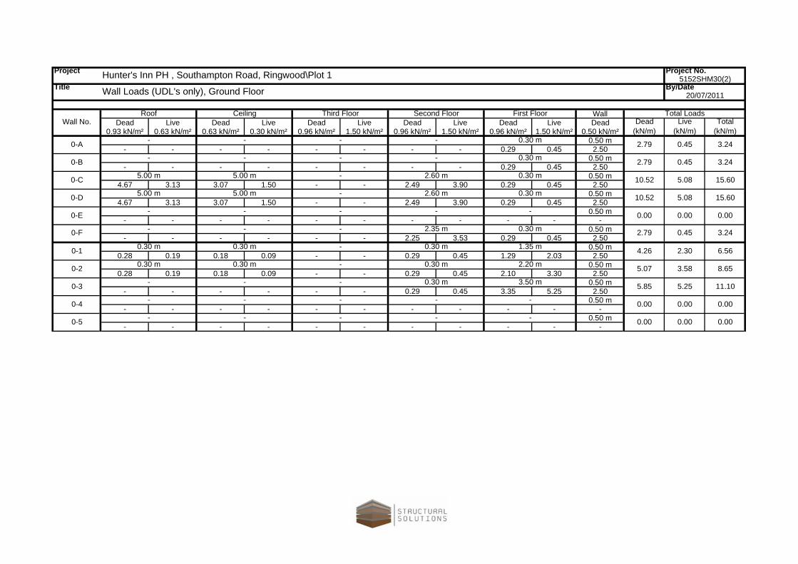
Project Project No.
Title By/Date
WallDead Live Dead Live Dead Live Dead Live Dead Live Dead
0.93 kN/m² 0.63 kN/m² 0.63 kN/m² 0.30 kN/m² 0.96 kN/m² 1.50 kN/m² 0.96 kN/m² 1.50 kN/m² 0.96 kN/m² 1.50 kN/m² 0.50 kN/m²0.50 m
- - - - - - - - 0.29 0.45 2.500.50 m
- - - - - - - - 0.29 0.45 2.500.50 m
4.67 3.13 3.07 1.50 - - 2.49 3.90 0.29 0.45 2.500.50 m
4.67 3.13 3.07 1.50 - - 2.49 3.90 0.29 0.45 2.500.50 m
- - - - - - - - - - -0.50 m
- - - - - - 2.25 3.53 0.29 0.45 2.500.50 m
0.28 0.19 0.18 0.09 - - 0.29 0.45 1.29 2.03 2.500.50 m
0.28 0.19 0.18 0.09 - - 0.29 0.45 2.10 3.30 2.500.50 m
- - - - - - 0.29 0.45 3.35 5.25 2.500.50 m
- - - - - - - - - - -0.50 m
- - - - - - - - - - -- 0.00 0.00 0.000-5 - - --
- 0.00 0.00 0.000-4 - - --
3.50 m 5.85 5.25 11.100-3 - - 0.30 m-
2.20 m 5.07 3.58 8.650-2 0.30 m 0.30 m 0.30 m-
0-1 0.30 m 0.30 m 0.30 m- 1.35 m 4.26 2.30 6.56
0.30 m 10.52 5.08 15.60
0.30 m 2.79 0.45 3.240-B - - --
0.30 m 2.79 0.45 3.240-A - - --
First Floor Total LoadsDead
(kN/m)Live
(kN/m)Total
(kN/m)Wall No.
Roof Ceiling Second FloorThird Floor
3.24
0.00 0.00
0-F - - 2.35 m 2.79 0.450.30 m
0-E - - --
-
10.52 5.08 15.60
-
0.30 m
0.00
0-D 5.00 m 5.00 m 2.60 m-
0-C 5.00 m 5.00 m 2.60 m-
20/07/2011
Hunter's Inn PH , Southampton Road, Ringwood\Plot 1
Wall Loads (UDL's only), Ground Floor5152SHM30(2)

Project
Hunter's Inn PH , Southampton Road, Ringwood\Plot 1Sheet no./rev.
5152SHM30(2)
Wind Load By/Date
RD / 19 July 2011
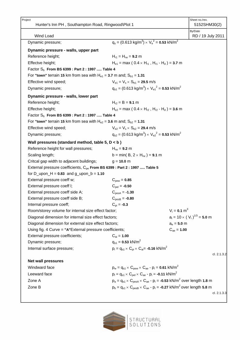
BUILDING WIND LOADING TO BS6399:PART2: 1997 TEDDS calculation version 2.0.00
Building data (duo-pitch roof) Longer horizontal dimension of the building L = 9.1 m Shorter horizontal dimension of the building W = 7.6 m Maximum height of the building H = 9.2 m Roof pitch angle (-ve for a valley roof) α = 35.0 deg Reference height for roof pressure Hrr = H = 9.2 m Reference height for wall pressure Hrw = 9.2 m
Dynamic classification Building type factor (table 1); Kb = 1.0 Maximum height of the building H = 9.2 m Dynamic augmentation factor (1.6.1); Cr = [Kb × ( H / (0.1 m) )0.75] / ( 800 × log( H / (0.1 m) ) ) = 0.02 Calcs valid - Standard/Hybrid method is applicable Orthogonal dimensions D = W = 7.6 m B = L = 9.1 m
Site wind speed NB Calcs suitable only where topography is not significant (cl. 2.2.2.2.1 & fig. 7) Cross-wind width of building; B = 9.1 m
Reference height for roof design; Hrr = 9.2 m Reference height for wall design; Hrw = 9.2 m Average height of roof tops of surrounding buildings; Ho = 7.0 m Upwind spacing of surrounding buildings; Xo = 10.0 m Basic wind speed (Figure 6 BS6399:Pt 2); Vb = 22.0 m/s Site altitude; ΔS = 21 m Upwind distance from sea to site; dsea = 15 km Altitude factor Sa = 1 + (0.001 m-1) × ΔS = 1.02 Direction factor; Sd =1.00 Seasonal factor Ss = 1.00 Probability factor Sp = 1.00 Site wind speed Vs = Vb × Sa × Sd × Ss × Sp = 22.5 m/s
Dynamic pressure – roof Displacement height; Hd = if( Xo ≤ ( 2 × Ho ), 0.8 × Ho, if( Xo < ( 6 × Ho ), 1.2 × Ho - 0.2 × Xo, 0 m )) = 5.6 m Effective height; He = max ( 0.4 × Hrr , Hrr - Hd ) = 3.7 m Factor Sb From BS 6399 : Part 2 : 1997 ..... Table 4 For "town" terrain 15 km from sea with He = 3.7 m; and Sb = 1.31 Effective wind speed; Ve = Vs × Sb = 29.5 m/s
Project
Hunter's Inn PH , Southampton Road, Ringwood\Plot 1Sheet no./rev.
5152SHM30(2)
Wind Load By/Date
RD / 19 July 2011Dynamic pressure; qs = (0.613 kg/m3) × Ve
2 = 0.53 kN/m2
Dynamic pressure - walls, upper part Reference height; Hr1 = Hrw = 9.2 m Effectve height; He1 = max ( 0.4 × Hr1 , Hr1 - Hd ) = 3.7 m Factor Sb From BS 6399 : Part 2 : 1997 ..... Table 4 For "town" terrain 15 km from sea with He1 = 3.7 m and; Sb1 = 1.31 Effective wind speed; Ve1 = Vs × Sb1 = 29.5 m/s Dynamic pressure; qs1 = (0.613 kg/m3) × Ve1
2 = 0.53 kN/m2
Dynamic pressure - walls, lower part Reference height; Hr2 = B = 9.1 m Effectve height; He2 = max ( 0.4 × Hr2 , Hr2 - Hd ) = 3.6 m Factor Sb From BS 6399 : Part 2 : 1997 ..... Table 4 For "town" terrain 15 km from sea with He2 = 3.6 m and; Sb2 = 1.31 Effective wind speed; Ve2 = Vs × Sb2 = 29.4 m/s Dynamic pressure; qs2 = (0.613 kg/m3) × Ve2
2 = 0.53 kN/m2
Wall pressures (standard method, table 5, D < b ) Reference height for wall pressures; Hrw = 9.2 m Scaling length; b = min( B, 2 × Hrw ) = 9.1 m Critcal gap width to adjacent buildings; g = 10.0 m External pressure coefficients, Cpe From BS 6399 : Part 2 : 1997 ..... Table 5 for D_upon_H = 0.83 and g_upon_b = 1.10 External pressure coeff w; Cpew = 0.85 External pressure coeff l; Cpel = -0.50 External pressure coeff side A; CpesA = -1.30 External pressure coeff side B; CpesB = -0.80 Internal pressure coeff; Cpi = -0.3 Room/storey volume for internal size effect factor; Vi = 0.1 m3
Diagonal dimension for internal size effect factors; ai = 10 × ( Vi )1/3 = 5.0 m Diagonal dimension for external size effect factors; ae = 5.0 m Using fig. 4 Curve = "A"External pressure coefficients; Cae = 1.00 External pressure coefficients; Cai = 1.00 Dynamic pressure; qs1 = 0.53 kN/m2
Internal surface pressure; pi = qs1 × Cpi × Cai= -0.16 kN/m2
cl. 2.1.3.2
Net wall pressures Windward face pw = qs1 × Cpew × Cae - pi = 0.61 kN/m2 Leeward face pl = qs1 × Cpel × Cae - pi = -0.11 kN/m2
Zone A pa = qs1 × CpesA × Cae - pi = -0.53 kN/m2 over length 1.8 m Zone B pb = qs1 × CpesB × Cae - pi = -0.27 kN/m2 over length 5.8 m
cl. 2.1.3.3

Project
Hunter's Inn PH , Southampton Road, Ringwood\Plot 1Sheet no./rev.
5152SHM30(2)
Wind Load By/Date
RD / 19 July 2011
Apex duopitch roof pressures (standard method, 0 degrees) Roof pressure coefficients From BS 6399 : Part 2 : 1997 ..... Table 10 for α = 35 deg & θ = 0 deg Roof pressure coefficient A1 CperA1 = 0.80 Roof pressure coefficient A2 CperA2 = -0.33 Roof pressure coefficient B1 CperB1 = 0.53 Roof pressure coefficient B2 CperB2 = -0.33 Roof pressure coefficient C1 CperC1 = 0.50 Roof pressure coefficient C2 CperC2 = -0.13 Roof pressure coefficient E1 CperE1 = -0.73 Roof pressure coefficient E2 CperE2 = -0.73 Roof pressure coefficient F1 CperF1 = -0.4 Roof pressure coefficient F2 CperF2 = -0.4 Roof pressure coefficient G1 CperG1 = -0.43 Roof pressure coefficient G2 CperG2 = -0.43 Diagonal dim for external pressures size effect fact aer = 5.0 m Room/storey volume for internal size effect factor Vir = 0.1 m3
Diagonal dimension for internal size effect factors air = 10× ( Vir )1/3 = 5.0 m Using fig. 4 Curve = "A" External size effect factor Caer = min(1.0, ka + kb × log( aer / ( 1 m ) ) ) = 1.00 Internal size effect factor Cair = min(1.0, ka + kb × log( air /( 1m ) ) ) = 1.00 Dynamic pressure qs = 0.53 kN/m2
Internal pressure coeff Cpi = -0.3 Internal surface pressure pir = qs × Cpi × Cair =-0.16 kN/m2
Net roof pressures Zone A+ prA1 = qs × CperA1 × Caer - pir = 0.59 kN/m2
Zone A prA2 = qs × CperA2 × Caer - pir = -0.02 kN/m2
Zone B+ prB1 = qs × CperB1 × Caer - pir = 0.44 kN/m2
Zone B prB2 = qs × CperB2 × Caer - pir = -0.02 kN/m2
Zone C+ prC1 = qs × CperC1 × Caer - pir = 0.43 kN/m2
Zone C prC2 = qs × CperC2 × Caer - pir = 0.09 kN/m2
Zone E+ prE1 = qs × CperE1 × Caer - pir = -0.23 kN/m2
Zone E prE2 = qs × CperE2 × Caer - pir = -0.23 kN/m2
Zone F+ prF1 = qs × CperF1 × Caer - pir = -0.07 kN/m2
Zone F prF2 = qs × CperF2 × Caer - pir = -0.07 kN/m2
Zone G+ prG1 = qs × CperG1 × Caer - pir = -0.07 kN/m2
Zone G prG2 = qs × CperG2 × Caer - pir = -0.07 kN/m2

Project
Hunter's Inn PH , Southampton Road, Ringwood\Plot 1Sheet no./rev.
5152SHM30(2)
Racking Load (front to back) By/Date
RD / 19 July 2011
RACKING LOADS DESIGN – BS6399-2:1997 TEDDS calculation version
1.0.05
Considering wind loads to the front elevation
General details
Building type; Dwelling
Overall height of building; H = 9.200 m
Number of storeys; 2
Depth of building; D = 7.600 m
Breadth of building; B = 9.100 m
Roof type; Duopitch
Roof pitch; α = 35.0 deg
Windloading details
Dynamic augmentation factor; Cr = 0.010
Dynamic pressure eaves level; qse = 0.530 kN/m2
Dynamic pressure roof level; qsr = 0.530 kN/m2
Wall details Area on elevation Pressure coefficient Size effect factor
Ground floor w/w elevation; Areaw0 = 19.000 m2; Cpew = 0.850; Caw0 = 1.000
Ground floor l/w elevation; Areal0 = 19.000 m2; Cpel = -0.500; Cal0 = 1.000
First floor w/w elevation; Areaw1 = 19.000 m2; Cpew = 0.850; Caw1 = 1.000
First floor l/w elevation; Areal1 = 19.000 m2; Cpel = -0.500; Cal1 = 1.000
Roof details Area on plan Pressure coefficient
Roof zone A; PlanA = 8.281 m2; CpeA = 0.800
Roof zone C; PlanC = 26.299 m2; CpeC = 0.500
Roof zone E; PlanE = 8.281 m2; CpeE = -0.733
Roof zone G; PlanG = 26.299 m2; CpeG = -0.433
Wind load transfer factor
Windward modification factor; K100w = 1.000
Leeward modification factor; K100l = 1.000
Project
Hunter's Inn PH , Southampton Road, Ringwood\Plot 1Sheet no./rev.
5152SHM30(2)
Racking Load (front to back) By/Date
RD / 19 July 2011
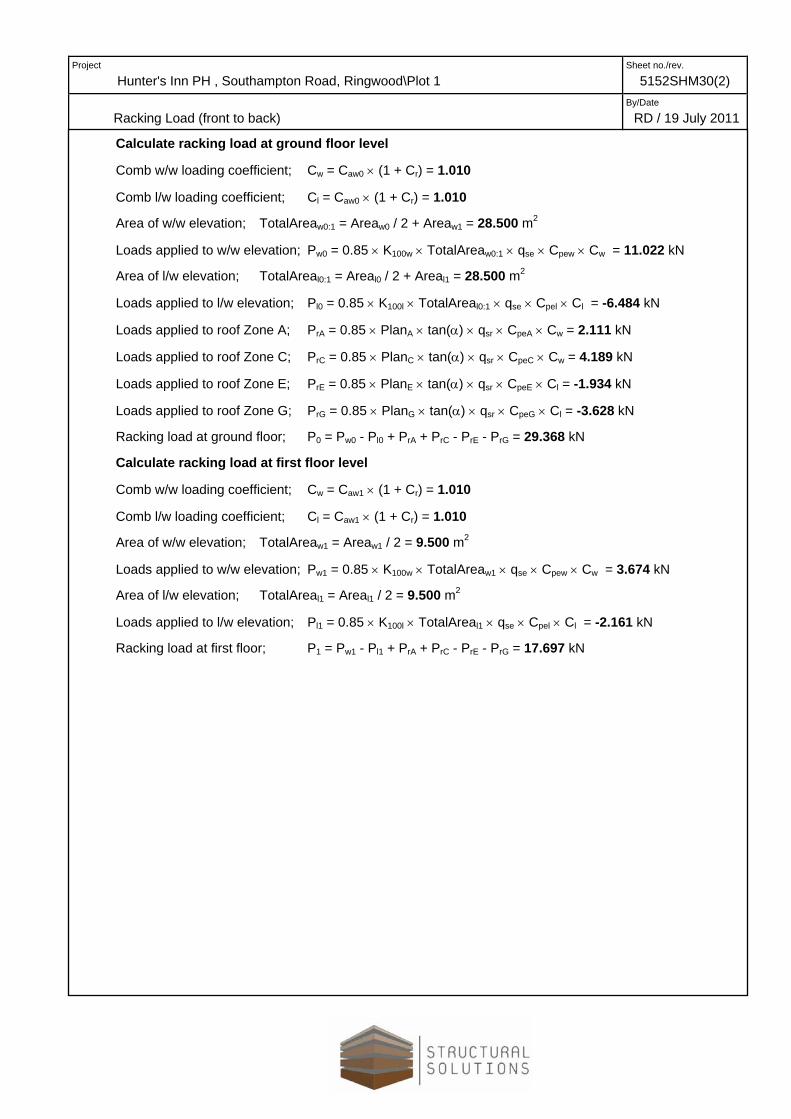
Calculate racking load at ground floor level
Comb w/w loading coefficient; Cw = Caw0 × (1 + Cr) = 1.010
Comb l/w loading coefficient; Cl = Caw0 × (1 + Cr) = 1.010
Area of w/w elevation; TotalAreaw0:1 = Areaw0 / 2 + Areaw1 = 28.500 m2
Loads applied to w/w elevation; Pw0 = 0.85 × K100w × TotalAreaw0:1 × qse × Cpew × Cw = 11.022 kN
Area of l/w elevation; TotalAreal0:1 = Areal0 / 2 + Areal1 = 28.500 m2
Loads applied to l/w elevation; Pl0 = 0.85 × K100l × TotalAreal0:1 × qse × Cpel × Cl = -6.484 kN
Loads applied to roof Zone A; PrA = 0.85 × PlanA × tan(α) × qsr × CpeA × Cw = 2.111 kN
Loads applied to roof Zone C; PrC = 0.85 × PlanC × tan(α) × qsr × CpeC × Cw = 4.189 kN
Loads applied to roof Zone E; PrE = 0.85 × PlanE × tan(α) × qsr × CpeE × Cl = -1.934 kN
Loads applied to roof Zone G; PrG = 0.85 × PlanG × tan(α) × qsr × CpeG × Cl = -3.628 kN
Racking load at ground floor; P0 = Pw0 - Pl0 + PrA + PrC - PrE - PrG = 29.368 kN
Calculate racking load at first floor level
Comb w/w loading coefficient; Cw = Caw1 × (1 + Cr) = 1.010
Comb l/w loading coefficient; Cl = Caw1 × (1 + Cr) = 1.010
Area of w/w elevation; TotalAreaw1 = Areaw1 / 2 = 9.500 m2
Loads applied to w/w elevation; Pw1 = 0.85 × K100w × TotalAreaw1 × qse × Cpew × Cw = 3.674 kN
Area of l/w elevation; TotalAreal1 = Areal1 / 2 = 9.500 m2
Loads applied to l/w elevation; Pl1 = 0.85 × K100l × TotalAreal1 × qse × Cpel × Cl = -2.161 kN
Racking load at first floor; P1 = Pw1 - Pl1 + PrA + PrC - PrE - PrG = 17.697 kN
Project
Hunter's Inn PH , Southampton Road, Ringwood\Plot 1 Sheet no./rev.
5152SHM30(2)
Racking Load (side to side) By/Date
RD / 19 July 2011
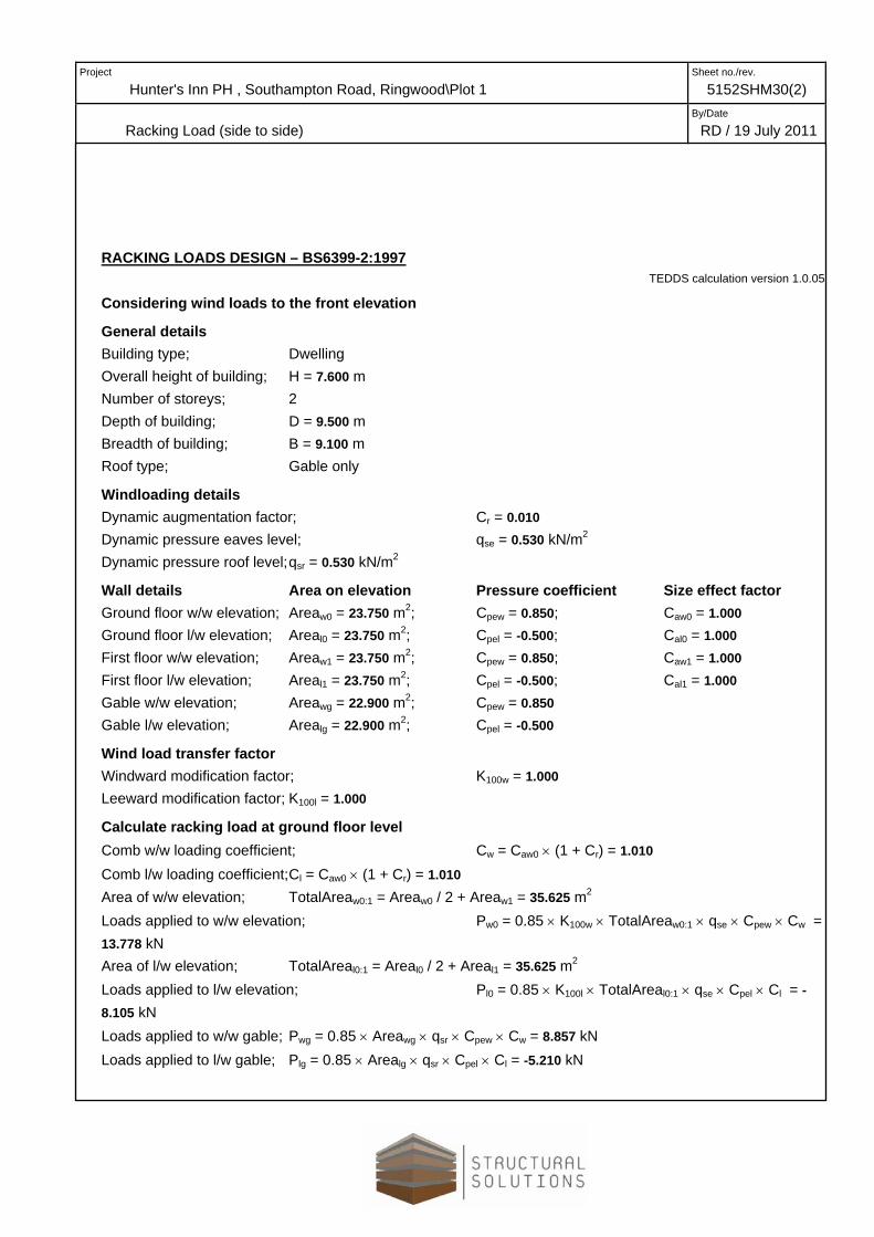
RACKING LOADS DESIGN – BS6399-2:1997 TEDDS calculation version 1.0.05
Considering wind loads to the front elevation
General details Building type; Dwelling Overall height of building; H = 7.600 m Number of storeys; 2 Depth of building; D = 9.500 m Breadth of building; B = 9.100 m Roof type; Gable only
Windloading details Dynamic augmentation factor; Cr = 0.010 Dynamic pressure eaves level; qse = 0.530 kN/m2 Dynamic pressure roof level; qsr = 0.530 kN/m2
Wall details Area on elevation Pressure coefficient Size effect factor Ground floor w/w elevation; Areaw0 = 23.750 m2; Cpew = 0.850; Caw0 = 1.000 Ground floor l/w elevation; Areal0 = 23.750 m2; Cpel = -0.500; Cal0 = 1.000 First floor w/w elevation; Areaw1 = 23.750 m2; Cpew = 0.850; Caw1 = 1.000 First floor l/w elevation; Areal1 = 23.750 m2; Cpel = -0.500; Cal1 = 1.000 Gable w/w elevation; Areawg = 22.900 m2; Cpew = 0.850 Gable l/w elevation; Arealg = 22.900 m2; Cpel = -0.500
Wind load transfer factor Windward modification factor; K100w = 1.000 Leeward modification factor; K100l = 1.000
Calculate racking load at ground floor level Comb w/w loading coefficient; Cw = Caw0 × (1 + Cr) = 1.010 Comb l/w loading coefficient; Cl = Caw0 × (1 + Cr) = 1.010 Area of w/w elevation; TotalAreaw0:1 = Areaw0 / 2 + Areaw1 = 35.625 m2 Loads applied to w/w elevation; Pw0 = 0.85 × K100w × TotalAreaw0:1 × qse × Cpew × Cw = 13.778 kN Area of l/w elevation; TotalAreal0:1 = Areal0 / 2 + Areal1 = 35.625 m2 Loads applied to l/w elevation; Pl0 = 0.85 × K100l × TotalAreal0:1 × qse × Cpel × Cl = -8.105 kN Loads applied to w/w gable; Pwg = 0.85 × Areawg × qsr × Cpew × Cw = 8.857 kN Loads applied to l/w gable; Plg = 0.85 × Arealg × qsr × Cpel × Cl = -5.210 kN
Project
Hunter's Inn PH , Southampton Road, Ringwood\Plot 1Sheet no./rev.
5152SHM30(2)
Racking Load (side to side) By/Date
RD / 19 July 2011Racking load at ground floor; P0 = Pw0 - Pl0 + Pwg - Plg = 35.949 kN
Calculate racking load at first floor level Comb w/w loading coefficient; Cw = Caw1 × (1 + Cr) = 1.010 Comb l/w loading coefficient; Cl = Caw1 × (1 + Cr) = 1.010 Area of w/w elevation; TotalAreaw1 = Areaw1 / 2 = 11.875 m2 Loads applied to w/w elevation; Pw1 = 0.85 × K100w × TotalAreaw1 × qse × Cpew × Cw = 4.593 kN Area of l/w elevation; TotalAreal1 = Areal1 / 2 = 11.875 m2 Loads applied to l/w elevation; Pl1 = 0.85 × K100l × TotalAreal1 × qse × Cpel × Cl = -2.702 kN Racking load at first floor; P1 = Pw1 - Pl1 + Pwg - Plg = 21.361 kN

Project
Title By/Date
Effective racking force = = 29.36 kN300mm 3.5Ø plasterboard screws 38mm long @ 300mm c/c
Racking resistance for sheathing (9mm OSB) = 1.68 kNRacking resistance for OSB (9mm) on OSB = 0.84 kNRacking resistance for p'board (12.5mm) on OSB = 0.12 kNRacking resistance for plasterboard (12.5mm) = 0.40 kNRacking resistance for p'board (12.5mm) on p'board = 0.20 kN
Km
k102 k104 k105 k106 k107
(-) (m) 1 2 (kN/m) (-) (-) (-) (-) (-) (kN)0-1 Ext 10.60 1.68 0.12 3.29 1.000 1.00 1.320 1.00 1.15 31.990-2 Ext 10.60 1.68 0.12 4.10 1.000 1.00 1.320 1.00 1.19 32.970-3 Int 3.46 0.40 0.20 4.88 1.000 1.00 1.158 1.00 1.35 3.570-4 Int 0.80 0.40 0.20 1.25 1.000 1.00 0.333 1.00 1.17 0.210-5 Int 0.80 0.40 0.20 2.25 1.000 1.00 0.333 1.00 1.30 0.23
Contribution from plasterboard 7.57 kNTotal racking resistance = kNTotal Racking Force = kNTotal racking resistance from OSB = kNTotal Contribution from Plasterboard = kN
Contribution from OSB relative to racking force =Therefore, contribution from plasterboard = <33% okay0%
Wall Type
209%
68.9529.3661.38
7.57
5152SHM30(2)
26 July 2011
Hunter's Inn PH , Southampton Road, Ringwood\Plot 1
Racking Loads, Ground Floor
Wall Length
Vertical Dead Load
Kw
Wall Ref
1st floor panel provide sufficient resistance by inspection
Check Racking for Front to Back Direction
Racking (To BS 5268 Part 6.1)
Plasterboard to be fixed at
Racking Materials
Racking Resistance
Racking.xls FRONT TO BACK (GF)

Project
Title By/Date
Effective racking force = = 35.95 kN300mm 3.5Ø plasterboard screws 38mm long @ 300mm c/c
Racking resistance for sheathing (9mm OSB) = 1.68 kNRacking resistance for OSB (9mm) on OSB = 0.84 kNRacking resistance for p'board (12.5mm) on OSB = 0.12 kNRacking resistance for plasterboard (12.5mm) = 0.40 kNRacking resistance for p'board (12.5mm) on p'board = 0.20 kN
Km
k102 k104 k105 k106 k107
(-) (m) 1 2 (kN/m) (-) (-) (-) (-) (-) (kN)0-A Ext 0.98 1.68 0.84 1.54 1.667 1.00 0.406 1.00 1.19 2.180-B Ext 0.98 1.68 0.84 1.54 1.667 1.00 0.406 1.00 1.19 2.180-C Ext 0.80 1.68 0.84 11.76 1.667 1.00 0.333 1.00 2.32 2.860-D Ext 0.80 1.68 0.84 11.76 1.667 1.00 0.333 1.00 2.32 2.860-E Wind 1.00 1.68 0.84 1.25 1.429 1.00 0.417 1.00 1.16 1.910-F Wind 1.00 1.68 0.84 3.78 1.429 1.00 0.417 1.00 1.45 2.400-G Wind 1.60 1.68 0.84 0.00 1.429 1.00 0.667 1.00 1.00 4.22
Contribution from plasterboard 0.00 kNTotal racking resistance = kNTotal Racking Force = kNTotal racking resistance from OSB = kNTotal Contribution from Plasterboard = kN
Contribution from OSB relative to racking force =Therefore, contribution from plasterboard = <33% okay
18.61
Wall RefWall Type
Wall Length
Racking Materials
Vertical Dead Load
Kw
Check Racking for Side to Side Direction
Racking (To BS 5268 Part 6.1)
Plasterboard to be fixed at
Hunter's Inn PH , Southampton Road, Ringwood\Plot 1
Racking Loads, Ground Floor 26 July 2011
5152SHM30(2)
Racking Resistance
0%
35.9518.61
0.00
52%Sway frame to provide 17.34kN of resistance
Racking.xls SIDE TO SIDE (GF)

Project
Title By/Date
Effective racking force = = 21.36 kN300mm 3.5Ø plasterboard screws 38mm long @ 300mm c/c
Racking resistance for sheathing (9mm OSB) = 1.68 kNRacking resistance for OSB (9mm) on OSB = 0.84 kNRacking resistance for p'board (12.5mm) on OSB = 0.12 kNRacking resistance for plasterboard (12.5mm) = 0.40 kNRacking resistance for p'board (12.5mm) on p'board = 0.20 kN
Km
k102 k104 k105 k106 k107
(-) (m) 1 2 (kN/m) (-) (-) (-) (-) (-) (kN)1-A Ext 0.98 1.68 0.00 0.00 1.429 1.00 0.406 1.00 1.00 1.051-B Ext 0.98 1.68 0.00 0.00 1.429 1.00 0.406 1.00 1.00 1.051-C Ext 0.82 1.68 0.00 0.00 1.429 1.00 0.343 1.00 1.00 0.751-D Ext 0.82 1.68 0.00 0.00 1.429 1.00 0.343 1.00 1.00 0.751-E Int 1.60 0.40 0.20 0.00 1.000 1.00 0.667 1.00 1.00 0.701-F Ext 0.62 1.68 0.00 0.00 1.429 1.00 0.258 1.00 1.00 0.421-G Ext 0.62 1.68 0.00 0.00 1.429 1.00 0.258 1.00 1.00 0.421-H Ext 0.94 1.68 0.00 0.00 1.429 1.00 0.393 1.00 1.00 0.981-J Ext 4.60 1.68 0.00 0.00 1.429 1.00 1.297 0.68 1.00 10.681-K Int 2.60 0.40 0.20 0.00 1.000 1.00 1.033 1.00 1.00 1.771-L Int 1.00 0.40 0.20 0.00 1.000 1.00 0.417 1.00 1.00 0.281-M Int 1.00 0.40 0.20 0.00 1.000 1.00 0.417 1.00 1.00 0.281-N Int 4.20 0.40 0.20 0.00 1.000 1.00 1.251 1.00 1.00 3.47
Contribution from plasterboard 5.90 kNTotal racking resistance = kNTotal Racking Force = kNTotal racking resistance from OSB = kNTotal Contribution from Plasterboard = kN
Contribution from OSB relative to racking force =Therefore, contribution from plasterboard = <33% okay
Racking Loads, First Floor 26 July 2011Check Racking for Side to Side Direction
Racking (To BS 5268 Part 6.1)
Hunter's Inn PH , Southampton Road, Ringwood\Plot 1 5152SHM30(2)
Racking Materials
Vertical Dead Load
Kw Racking Resistance
22%
22.5821.3616.68
78%
5.90
Plasterboard to be fixed at
Wall RefWall Type
Wall Length
Racking.xls SIDE TO SIDE (FF)
STRUCTURAL SOLUTIONSMANAGEMENT LTD
Software licensed to
Job Title
Client
Job No Sheet No Rev
Part
Ref
By Date Chd
File Date/Time
5152SHM30 1
Hunter's Inn PH , Southampton Road, Ringwood
Scandiahus Manufacturing
Plot 1 Sway frame
RD 04-08-11
29-Sep-2011 16:59Plot 1 hw.psa
Print Time/Date: 29/09/2011 17:01 Print Run 1 of 5STAAD.Pro - QSE Version 11.0
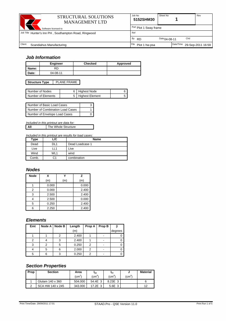
Job Information Engineer Checked Approved
Name: RDDate: 04-08-11
Structure Type PLANE FRAME
Number of Nodes 6 Highest Node 6Number of Elements 5 Highest Element 5
Number of Basic Load Cases 3Number of Combination Load Cases 1Number of Envelope Load Cases 0
Included in this printout are data for:All The Whole Structure
Included in this printout are results for load cases:Type L/C NameDead DL1 Dead Loadcase 1Live LL1 LiveWind WL1 wind
Comb. C1 combination
NodesNode X
(m)Y
(m)Z
(m)1 0.000 0.0002 0.000 2.4003 2.500 2.4004 2.500 0.0005 0.250 2.4006 2.250 2.400
ElementsEmt Node A Node B Length
(m)Prop A Prop B β
degrees1 1 2 2.400 1 - 02 4 3 2.400 1 - 03 2 5 0.250 2 - 04 5 6 2.000 2 - 05 6 3 0.250 2 - 0
Section PropertiesProp Section Area
(cm2)Iyy
(cm4)Izz
(cm4)J
(cm4)Material
1 Glulam 140 x 360 504.000 54.4E 3 8.23E 3 62 SCA HW 140 x 245 343.000 17.2E 3 5.6E 3 12
STRUCTURAL SOLUTIONSMANAGEMENT LTD
Software licensed to
Job Title
Client
Job No Sheet No Rev
Part
Ref
By Date Chd
File Date/Time
5152SHM30 2
Hunter's Inn PH , Southampton Road, Ringwood
Scandiahus Manufacturing
Plot 1 Sway frame
RD 04-08-11
29-Sep-2011 16:59Plot 1 hw.psa
Print Time/Date: 29/09/2011 17:01 Print Run 2 of 5STAAD.Pro - QSE Version 11.0
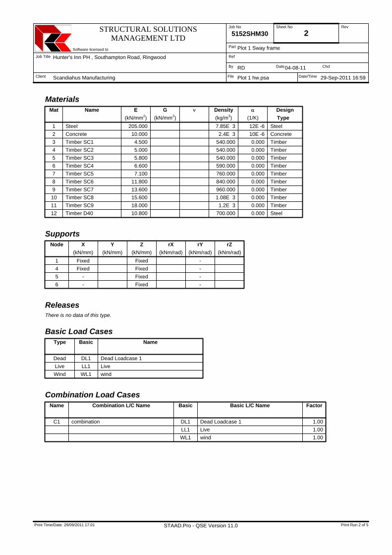
MaterialsMat Name E
(kN/mm2)G
(kN/mm2)ν Density
(kg/m3)α
(1/K)DesignType
1 Steel 205.000 7.85E 3 12E -6 Steel2 Concrete 10.000 2.4E 3 10E -6 Concrete3 Timber SC1 4.500 540.000 0.000 Timber4 Timber SC2 5.000 540.000 0.000 Timber5 Timber SC3 5.800 540.000 0.000 Timber6 Timber SC4 6.600 590.000 0.000 Timber7 Timber SC5 7.100 760.000 0.000 Timber8 Timber SC6 11.800 840.000 0.000 Timber9 Timber SC7 13.600 960.000 0.000 Timber10 Timber SC8 15.600 1.08E 3 0.000 Timber11 Timber SC9 18.000 1.2E 3 0.000 Timber12 Timber D40 10.800 700.000 0.000 Steel
SupportsNode X
(kN/mm)Y
(kN/mm)Z
(kN/mm)rX
(kNm/rad)rY
(kNm/rad)rZ
(kNm/rad)1 Fixed Fixed -4 Fixed Fixed -5 - Fixed -6 - Fixed -
ReleasesThere is no data of this type.
Basic Load CasesType Basic Name
Dead DL1 Dead Loadcase 1Live LL1 LiveWind WL1 wind
Combination Load CasesName Combination L/C Name Basic Basic L/C Name Factor
C1 combination DL1 Dead Loadcase 1 1.00LL1 Live 1.00WL1 wind 1.00
STRUCTURAL SOLUTIONSMANAGEMENT LTD
Software licensed to
Job Title
Client
Job No Sheet No Rev
Part
Ref
By Date Chd
File Date/Time
5152SHM30 3
Hunter's Inn PH , Southampton Road, Ringwood
Scandiahus Manufacturing
Plot 1 Sway frame
RD 04-08-11
29-Sep-2011 16:59Plot 1 hw.psa
Print Time/Date: 29/09/2011 17:01 Print Run 3 of 5STAAD.Pro - QSE Version 11.0
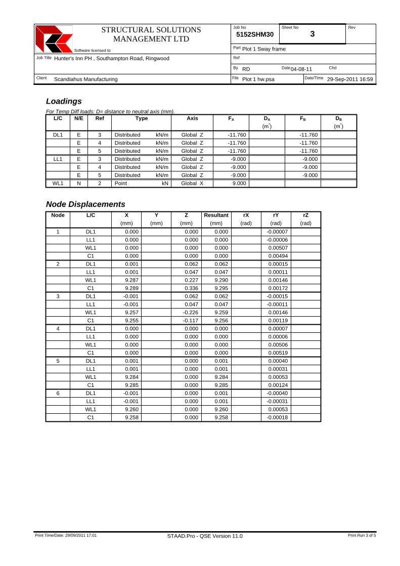
LoadingsFor Temp Diff loads: D= distance to neutral axis (mm).
L/C N/E Ref Type Axis FA DA
(m*)FB DB
(m*)DL1 E 3 Distributed kN/m Global Z -11.760 -11.760
E 4 Distributed kN/m Global Z -11.760 -11.760E 5 Distributed kN/m Global Z -11.760 -11.760
LL1 E 3 Distributed kN/m Global Z -9.000 -9.000E 4 Distributed kN/m Global Z -9.000 -9.000E 5 Distributed kN/m Global Z -9.000 -9.000
WL1 N 2 Point kN Global X 9.000
Node DisplacementsNode L/C X
(mm)Y
(mm)Z
(mm)Resultant
(mm)rX
(rad)rY
(rad)rZ
(rad)1 DL1 0.000 0.000 0.000 -0.00007
LL1 0.000 0.000 0.000 -0.00006WL1 0.000 0.000 0.000 0.00507C1 0.000 0.000 0.000 0.00494
2 DL1 0.001 0.062 0.062 0.00015LL1 0.001 0.047 0.047 0.00011WL1 9.287 0.227 9.290 0.00146C1 9.289 0.336 9.295 0.00172
3 DL1 -0.001 0.062 0.062 -0.00015LL1 -0.001 0.047 0.047 -0.00011WL1 9.257 -0.226 9.259 0.00146C1 9.255 -0.117 9.256 0.00119
4 DL1 0.000 0.000 0.000 0.00007LL1 0.000 0.000 0.000 0.00006WL1 0.000 0.000 0.000 0.00506C1 0.000 0.000 0.000 0.00519
5 DL1 0.001 0.000 0.001 0.00040LL1 0.001 0.000 0.001 0.00031WL1 9.284 0.000 9.284 0.00053C1 9.285 0.000 9.285 0.00124
6 DL1 -0.001 0.000 0.001 -0.00040LL1 -0.001 0.000 0.001 -0.00031WL1 9.260 0.000 9.260 0.00053C1 9.258 0.000 9.258 -0.00018
STRUCTURAL SOLUTIONSMANAGEMENT LTD
Software licensed to
Job Title
Client
Job No Sheet No Rev
Part
Ref
By Date Chd
File Date/Time
5152SHM30 4
Hunter's Inn PH , Southampton Road, Ringwood
Scandiahus Manufacturing
Plot 1 Sway frame
RD 04-08-11
29-Sep-2011 16:59Plot 1 hw.psa
Print Time/Date: 29/09/2011 17:01 Print Run 4 of 5STAAD.Pro - QSE Version 11.0
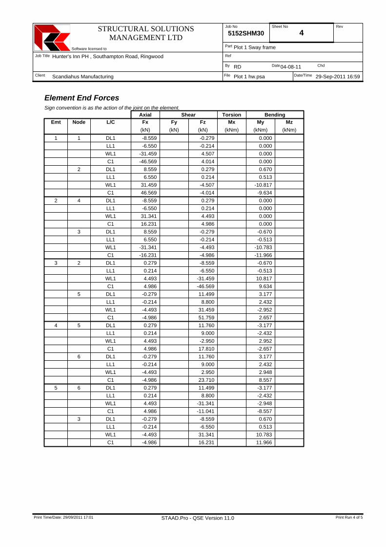
Element End ForcesSign convention is as the action of the joint on the element.
Axial Shear Torsion BendingEmt Node L/C Fx
(kN)Fy
(kN)Fz
(kN)Mx
(kNm)My
(kNm)Mz
(kNm)1 1 DL1 -8.559 -0.279 0.000
LL1 -6.550 -0.214 0.000WL1 -31.459 4.507 0.000C1 -46.569 4.014 0.000
2 DL1 8.559 0.279 0.670LL1 6.550 0.214 0.513WL1 31.459 -4.507 -10.817C1 46.569 -4.014 -9.634
2 4 DL1 -8.559 0.279 0.000LL1 -6.550 0.214 0.000WL1 31.341 4.493 0.000C1 16.231 4.986 0.000
3 DL1 8.559 -0.279 -0.670LL1 6.550 -0.214 -0.513WL1 -31.341 -4.493 -10.783C1 -16.231 -4.986 -11.966
3 2 DL1 0.279 -8.559 -0.670LL1 0.214 -6.550 -0.513WL1 4.493 -31.459 10.817C1 4.986 -46.569 9.634
5 DL1 -0.279 11.499 3.177LL1 -0.214 8.800 2.432WL1 -4.493 31.459 -2.952C1 -4.986 51.759 2.657
4 5 DL1 0.279 11.760 -3.177LL1 0.214 9.000 -2.432WL1 4.493 -2.950 2.952C1 4.986 17.810 -2.657
6 DL1 -0.279 11.760 3.177LL1 -0.214 9.000 2.432WL1 -4.493 2.950 2.948C1 -4.986 23.710 8.557
5 6 DL1 0.279 11.499 -3.177LL1 0.214 8.800 -2.432WL1 4.493 -31.341 -2.948C1 4.986 -11.041 -8.557
3 DL1 -0.279 -8.559 0.670LL1 -0.214 -6.550 0.513WL1 -4.493 31.341 10.783C1 -4.986 16.231 11.966
STRUCTURAL SOLUTIONSMANAGEMENT LTD
Software licensed to
Job Title
Client
Job No Sheet No Rev
Part
Ref
By Date Chd
File Date/Time
5152SHM30 5
Hunter's Inn PH , Southampton Road, Ringwood
Scandiahus Manufacturing
Plot 1 Sway frame
RD 04-08-11
29-Sep-2011 16:59Plot 1 hw.psa
Print Time/Date: 29/09/2011 17:01 Print Run 5 of 5STAAD.Pro - QSE Version 11.0
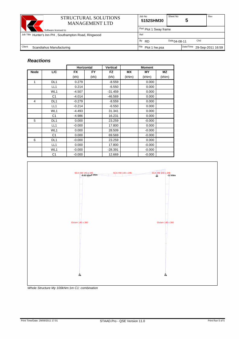
ReactionsHorizontal Vertical Moment
Node L/C FX(kN)
FY(kN)
FZ(kN)
MX(kNm)
MY(kNm)
MZ(kNm)
1 DL1 0.279 -8.559 0.000LL1 0.214 -6.550 0.000WL1 -4.507 -31.459 0.000C1 -4.014 -46.569 0.000
4 DL1 -0.279 -8.559 0.000LL1 -0.214 -6.550 0.000WL1 -4.493 31.341 0.000C1 -4.986 16.231 0.000
5 DL1 0.000 23.259 -0.000LL1 -0.000 17.800 0.000WL1 0.000 28.509 -0.000C1 0.000 69.569 -0.000
6 DL1 -0.000 23.259 0.000LL1 0.000 17.800 -0.000WL1 -0.000 -28.391 -0.000C1 -0.000 12.669 -0.000
Glulam 140 x 360 Glulam 140 x 360
SCA HW 140 x 245 SCA HW 140 x 245 SCA HW 140 x 245-12 kNm2.66 kNm-9.63 kNm
Whole Structure My 100kNm:1m C1: combination

Project
Hunter's Inn PH , Southampton Road, Ringwood\Plot 1Sheet no./rev.
5152SHM30(2)
Sway frame beam capacity By/Date
RD / 05/8/2011
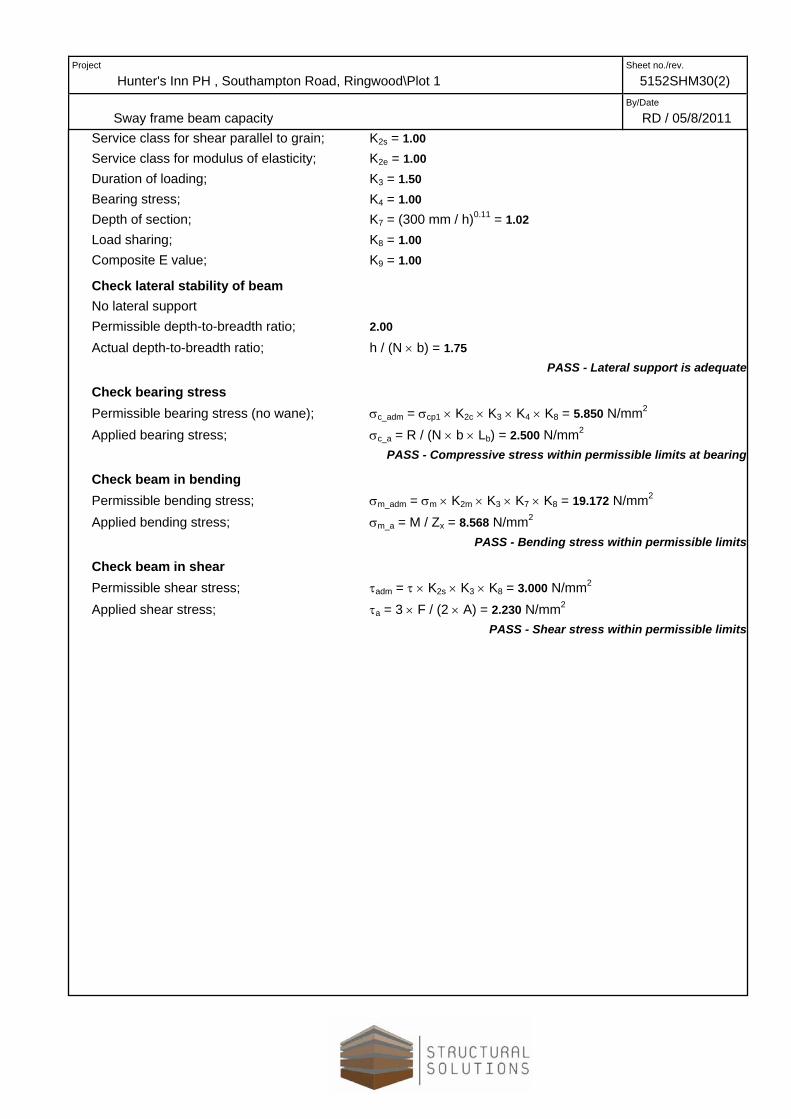
TIMBER BEAM DESIGN TO BS5268-2:2002 TEDDS calculation version 1.3.00
Analysis results Design moment; M = 12.000 kNm Design shear; F = 51.000 kN Maximum reaction; R = 35.000 kN
Timber section details Breadth of timber sections; b = 140 mm Depth of timber sections; h = 245 mm Number of timber sections in beam; N = 1 Overall breadth of timber beam; bb = N × b = 140 mm Timber strength class; D40
Beam details Length of bearing; Lb = 100 mm Service class of timber; 1 Load duration; Short term
Section properties Cross sectional area of beam; A = N × b × h = 34300 mm2 Section modulus; Zx = N × b × h2 / 6 = 1400583 mm3 Zy = h × (N × b)2 / 6 = 800333 mm3 Second moment of area; Ix = N × b × h3 / 12 = 171571458 mm4 Iy = h × (N × b)3 / 12 = 56023333 mm4 Radius of gyration; rx = √(Ix / A) = 70.7 mm ry = √(Iy / A) = 40.4 mm
Modification factors Service class for bending parallel to grain; K2m = 1.00 Service class for tension parallel to grain; K2t = 1.00 Service class for compression; K2c = 1.00
Project
Hunter's Inn PH , Southampton Road, Ringwood\Plot 1 Sheet no./rev.
5152SHM30(2)
Sway frame beam capacity By/Date
RD / 05/8/2011 Service class for shear parallel to grain; K2s = 1.00 Service class for modulus of elasticity; K2e = 1.00 Duration of loading; K3 = 1.50 Bearing stress; K4 = 1.00 Depth of section; K7 = (300 mm / h)0.11 = 1.02 Load sharing; K8 = 1.00 Composite E value; K9 = 1.00
Check lateral stability of beam No lateral support Permissible depth-to-breadth ratio; 2.00 Actual depth-to-breadth ratio; h / (N × b) = 1.75
PASS - Lateral support is adequate Check bearing stress Permissible bearing stress (no wane); σc_adm = σcp1 × K2c × K3 × K4 × K8 = 5.850 N/mm2 Applied bearing stress; σc_a = R / (N × b × Lb) = 2.500 N/mm2
PASS - Compressive stress within permissible limits at bearing Check beam in bending Permissible bending stress; σm_adm = σm × K2m × K3 × K7 × K8 = 19.172 N/mm2 Applied bending stress; σm_a = M / Zx = 8.568 N/mm2
PASS - Bending stress within permissible limits Check beam in shear Permissible shear stress; τadm = τ × K2s × K3 × K8 = 3.000 N/mm2 Applied shear stress; τa = 3 × F / (2 × A) = 2.230 N/mm2
PASS - Shear stress within permissible limits
Project
Hunter's Inn PH , Southampton Road, Ringwood\Plot 1 Sheet no./rev.
5152SHM30(2)
Sway frame connections By/Date
RD / 05/8/2011
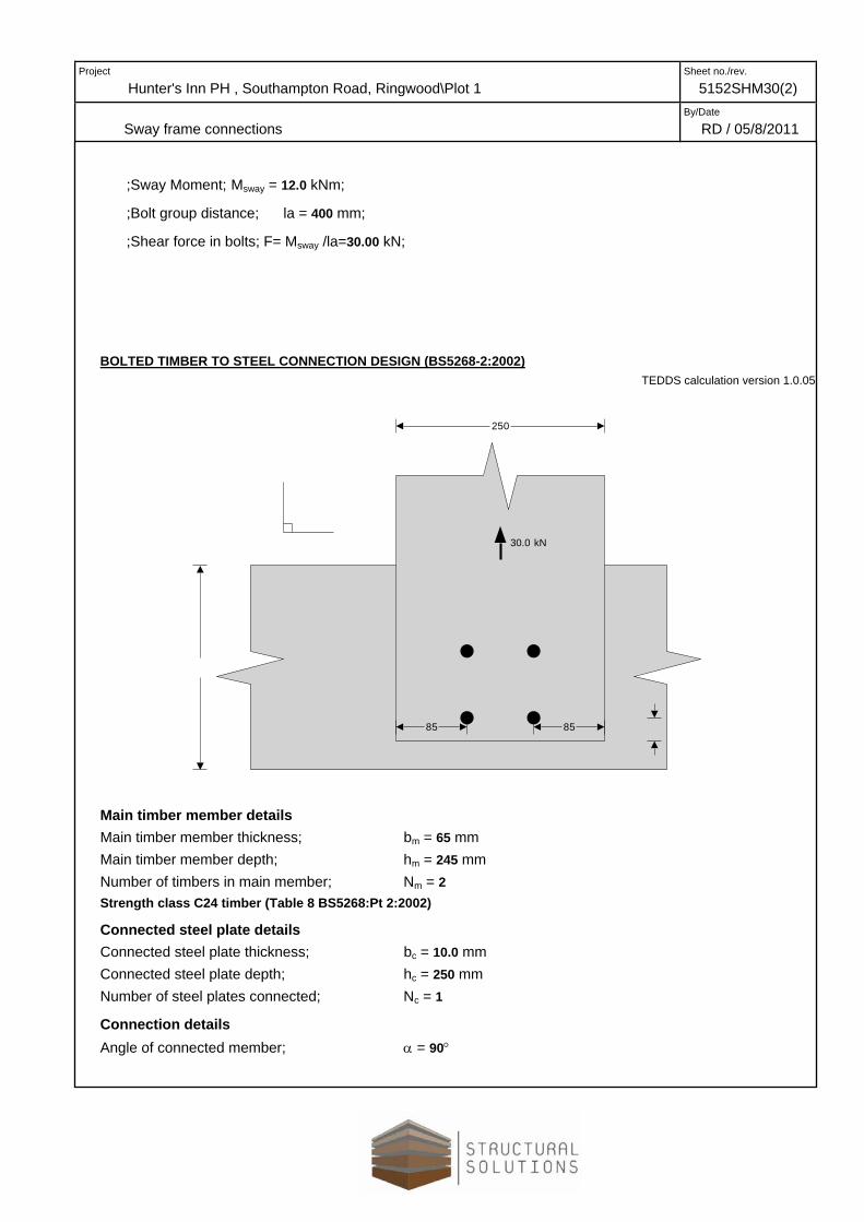
;Sway Moment; Msway = 12.0 kNm;
;Bolt group distance; la = 400 mm;
;Shear force in bolts; F= Msway /la=30.00 kN;
BOLTED TIMBER TO STEEL CONNECTION DESIGN (BS5268-2:2002) TEDDS calculation version 1.0.05
30.0 kN
250
85 85
Main timber member details Main timber member thickness; bm = 65 mm Main timber member depth; hm = 245 mm Number of timbers in main member; Nm = 2 Strength class C24 timber (Table 8 BS5268:Pt 2:2002)
Connected steel plate details Connected steel plate thickness; bc = 10.0 mm Connected steel plate depth; hc = 250 mm Number of steel plates connected; Nc = 1
Connection details Angle of connected member; α = 90°
Project
Hunter's Inn PH , Southampton Road, Ringwood\Plot 1Sheet no./rev.
5152SHM30(2)
Sway frame connections By/Date
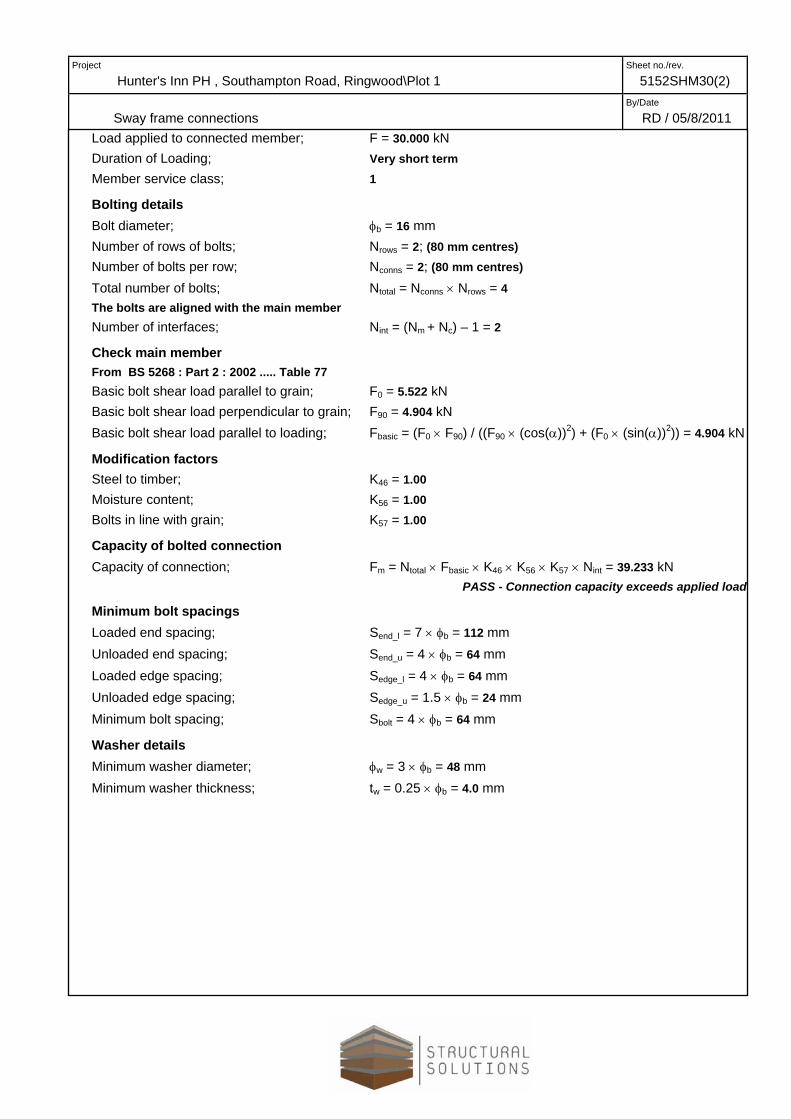
RD / 05/8/2011 Load applied to connected member; F = 30.000 kN Duration of Loading; Very short term Member service class; 1
Bolting details Bolt diameter; φb = 16 mm Number of rows of bolts; Nrows = 2; (80 mm centres) Number of bolts per row; Nconns = 2; (80 mm centres) Total number of bolts; Ntotal = Nconns × Nrows = 4 The bolts are aligned with the main member Number of interfaces; Nint = (Nm + Nc) – 1 = 2
Check main member From BS 5268 : Part 2 : 2002 ..... Table 77 Basic bolt shear load parallel to grain; F0 = 5.522 kN Basic bolt shear load perpendicular to grain; F90 = 4.904 kN Basic bolt shear load parallel to loading; Fbasic = (F0 × F90) / ((F90 × (cos(α))2) + (F0 × (sin(α))2)) = 4.904 kN
Modification factors Steel to timber; K46 = 1.00 Moisture content; K56 = 1.00 Bolts in line with grain; K57 = 1.00
Capacity of bolted connection Capacity of connection; Fm = Ntotal × Fbasic × K46 × K56 × K57 × Nint = 39.233 kN
PASS - Connection capacity exceeds applied load Minimum bolt spacings Loaded end spacing; Send_l = 7 × φb = 112 mm Unloaded end spacing; Send_u = 4 × φb = 64 mm Loaded edge spacing; Sedge_l = 4 × φb = 64 mm Unloaded edge spacing; Sedge_u = 1.5 × φb = 24 mm Minimum bolt spacing; Sbolt = 4 × φb = 64 mm
Washer details Minimum washer diameter; φw = 3 × φb = 48 mm Minimum washer thickness; tw = 0.25 × φb = 4.0 mm

Project
Hunter's Inn PH , Southampton Road, Ringwood\Plot 1Sheet no./rev.
5152SHM30(3)
Internal Studs By/Date
RD / 19 July 2011
WallDead Live Dead Live Dead Live Dead Live Dead Dead Live Total
0-F 0.93 0.63 0.61 0.30 0.96 1.50 0.96 1.50 0.500.00 0.00 0.00 0.00 2.35 2.35 0.30 0.30 2.500.00 0.00 0.00 0.00 2.25 3.53 0.29 0.45 1.25 3.78 3.98 7.76
Stud Ref. Roof Ceiling Second Floor First Floor Total Loads
TIMBER STUD DESIGN (BS5268-2:2002) TEDDS calculation version 1.0.03
h
b
b
b
ss
LL s
U kN/m
Stud details Stud breadth; b = 38 mm Stud depth; h = 89 mm Number of studs; Ns = 1 Strength class C16 timber (Table 8 BS5268:Pt 2:2002)
Section properties Cross sectional area; A = Ns × b × h = 3382 mm2 Section modulus; Z = Ns × b × h2 / 6 = 50166 mm3 Moment of inertia in the major axis; Ix = Ns × b × h3 / 12 = 2232402 mm4 Moment of inertia in the minor axis; Iy = Ns × h × b3 / 12 = 406967 mm4 Radius of gyration in the major axis; rx = √(Ix / A) = 25.7 mm Radius of gyration in the minor axis; ry = √(Iy / A) = 11.0 mm
Panel details - Studs restrained by sheathing in the plane of the panel Panel height; L = 2400 mm Stud length; Ls = L – (2 × b) = 2324 mm
Project
Hunter's Inn PH , Southampton Road, Ringwood\Plot 1 Sheet no./rev.
5152SHM30(3)
Internal Studs By/Date
RD / 19 July 2011Standard stud spacing; ss = 600 mm Panel opening; O = 0 mm Loaded panel length; s = max(ss, (O + ss) / 2) = 600 mm Effective length in the major axis; Lex = 0.85 × Ls = 1975 mm Slenderness ratio; λ = Lex / rx = 76.89
Vertical loading details Dead loads Imposed loads Wall UDL; Uw_d = 1.25 kN/m Floor UDL; Uf_d = 2.48 kN/m; Uf_i = 3.98 kN/m Imposed floor load duration; Long term
Modification factors Section depth factor; K7 = (300 mm / h)0.11 = 1.14 Load sharing factor; K8 = 1.10
Consider axial compression without bending under long term loads Load duration factor; K3 = 1.00 Vertical loading; F = (Uw_d + Uf_d + Uf_i) × s = 4.63 kN
Check compressive stress on stud Compression member factor; K12 = 0.53 Compression parallel to grain; σc = 6.800 N/mm2 Permissible compressive stress; σc_adm = σc × K3 × K8 × K12 = 3.986 N/mm2 Applied compressive stress; σc_max = F / (Ns × b × h) = 1.368 N/mm2
PASS - Applied compressive stress under long term loads is within permissible limits Check compressive stress on rail Bearing stress modification factor; K4 = 1.36 Compression perpendicular to grain (no wane); σcp1 = 2.200 N/mm2 Permissible compressive stress; σcp1_adm = σcp1 × K3 × K4 = 2.985 N/mm2 Applied compressive stress; σcp1_max = F / (Ns × b × h) = 1.368 N/mm2
PASS - Applied compressive stress under long term loads is within permissible limits

Project
Hunter's Inn PH , Southampton Road, Ringwood\Plot 1 Sheet no./rev.
5152SHM30(3)
External Studs By/Date
RD / 19 July 2011
WallDead Live Dead Live Dead Live Dead Live Dead Dead Live Total
0-C 0.93 0.63 0.61 0.30 0.96 1.50 0.96 1.50 0.505.00 5.00 5.00 5.00 2.60 2.60 0.30 0.30 2.504.67 3.13 3.07 1.50 2.49 3.90 0.29 0.45 1.25 11.76 8.98 20.74
Second Floor First Floor Total LoadsStud Ref. Roof Ceiling
TIMBER STUD DESIGN (BS5268-2:2002) TEDDS calculation version 1.0.03
h
b
b
b
ss
LL s
W k
N/m
2
U kN/m
Stud details Stud breadth; b = 38 mm Stud depth; h = 140 mm Number of studs; Ns = 1 Strength class C16 timber (Table 8 BS5268:Pt 2:2002)
Section properties Cross sectional area; A = Ns × b × h = 5320 mm2 Section modulus; Z = Ns × b × h2 / 6 = 124133 mm3 Moment of inertia in the major axis; Ix = Ns × b × h3 / 12 = 8689333 mm4 Moment of inertia in the minor axis; Iy = Ns × h × b3 / 12 = 640173 mm4 Radius of gyration in the major axis; rx = √(Ix / A) = 40.4 mm Radius of gyration in the minor axis; ry = √(Iy / A) = 11.0 mm
Panel details - Studs restrained by sheathing in the plane of the panel Panel height; L = 2400 mm Stud length; Ls = L – (2 × b) = 2324 mm
Project
Hunter's Inn PH , Southampton Road, Ringwood\Plot 1Sheet no./rev.
5152SHM30(3)
External Studs By/Date
RD / 19 July 2011Standard stud spacing; ss = 600 mm Panel opening; O = 0 mm Loaded panel length; s = max(ss, (O + ss) / 2) = 600 mm Effective length in the major axis; Lex = 0.85 × Ls = 1975 mm Slenderness ratio; λ = Lex / rx = 48.88
Vertical loading details Dead loads Imposed loads Wall UDL; Uw_d = 1.25 kN/m Roof UDL; Ur_d = 8.20 kN/m; Ur_i = 4.90 kN/m Floor UDL; Uf_d = 2.78 kN/m; Uf_i = 4.35 kN/m Imposed floor load duration; Long term
Lateral loading details Wind loading; W = 0.61 kN/m2 Wind load duration; Very short term
Modification factors Section depth factor; K7 = (300 mm / h)0.11 = 1.09 Load sharing factor; K8 = 1.10
Consider combined axial compression and bending under very short term loads Load duration factor; K3 = 1.75 Vertical loading; F = (Uw_d + Ur_d + Uf_d + Ur_i + Uf_i) × s = 12.89 kN
Check bending stress Bending parallel to grain; σm = 5.300 N/mm2 Permissible bending stress; σm_adm = σm × K3 × K7 × K8 = 11.095 N/mm2 Bending moment; Mmax = W × s × L2 / 8 = 0.264 kNm Applied bending stress; σm_max = Mmax / Z = 2.123 N/mm2
PASS - Applied bending stress under very short term loads is within permissible limits Check compressive stress on stud Compression member factor; K12 = 0.67 Compression parallel to grain; σc = 6.800 N/mm2 Permissible compressive stress; σc_adm = σc × K3 × K8 × K12 = 8.791 N/mm2 Applied compressive stress; σc_max = F / (Ns × b × h) = 2.423 N/mm2
PASS - Applied compressive stress under very short term loads is within permissible limits Check compressive stress on rail Bearing stress modification factor; K4 = 1.36 Compression perpendicular to grain (no wane); σcp1 = 2.200 N/mm2 Permissible compressive stress; σcp1_adm = σcp1 × K3 × K4 = 5.223 N/mm2 Applied compressive stress; σcp1_max = F / (Ns × b × h) = 2.423 N/mm2
PASS - Applied compressive stress under very short term loads is within permissible limits

Project
Hunter's Inn PH , Southampton Road, Ringwood\Plot 1 Sheet no./rev.
5152SHM30(3)
External Studs By/Date
RD / 19 July 2011
Check combined axial compression and bending Euler critical stress; σe = (π2 × Emin) / λ2 = 23.960 N/mm2 Euler coefficient; Keu = 1 – (1.5 × σc_max × K12 / σe) = 0.898 Combined axial compression and bending value; K = σm_max / (σm_adm × Keu) + σc_max / σc_adm = 0.489; < 1
PASS - Combined compressive and bending stresses under very short term loads are within permissible limits Check stud deflection Maximum deflection; δadm = min(7.0 mm, 0.003 × (L - 2 × b)) = 6.972 mm Bending deflection; δmax = 5 × W × s × Ls
4 / (384 × Emean × Ix) = 1.818 mm PASS - Deflection due to wind loading is less than permissible limit
Consider axial compression without bending under medium term loads Load duration factor; K3 = 1.25 Vertical loading; F = (Uw_d + Ur_d + Uf_d + Ur_i + Uf_i) × s = 12.89 kN
Check compressive stress on stud Compression member factor; K12 = 0.72 Compression parallel to grain; σc = 6.800 N/mm2 Permissible compressive stress; σc_adm = σc × K3 × K8 × K12 = 6.702 N/mm2 Applied compressive stress; σc_max = F / (Ns × b × h) = 2.423 N/mm2
PASS - Applied compressive stress under medium term loads is within permissible limits Check compressive stress on rail Bearing stress modification factor; K4 = 1.36 Compression perpendicular to grain (no wane); σcp1 = 2.200 N/mm2 Permissible compressive stress; σcp1_adm = σcp1 × K3 × K4 = 3.731 N/mm2 Applied compressive stress; σcp1_max = F / (Ns × b × h) = 2.423 N/mm2
PASS - Applied compressive stress under medium term loads is within permissible limits Consider axial compression without bending under long term loads Load duration factor; K3 = 1.00 Vertical loading; F = (Uw_d + Ur_d + Uf_d + Uf_i) × s = 9.95 kN
Check compressive stress on stud Compression member factor; K12 = 0.74 Compression parallel to grain; σc = 6.800 N/mm2 Permissible compressive stress; σc_adm = σc × K3 × K8 × K12 = 5.515 N/mm2 Applied compressive stress; σc_max = F / (Ns × b × h) = 1.870 N/mm2
PASS - Applied compressive stress under long term loads is within permissible limits Check compressive stress on rail Bearing stress modification factor; K4 = 1.36 Compression perpendicular to grain (no wane); σcp1 = 2.200 N/mm2 Permissible compressive stress; σcp1_adm = σcp1 × K3 × K4 = 2.985 N/mm2 Applied compressive stress; σcp1_max = F / (Ns × b × h) = 1.870 N/mm2

Project
Hunter's Inn PH , Southampton Road, Ringwood\Plot 1 Sheet no./rev.
5152SHM30(3)
External Studs By/Date
RD / 19 July 2011PASS - Applied compressive stress under long term loads is within permissible limits

Project
Hunter's Inn PH , Southampton Road, Ringwood\Plot 1Sheet no./rev.
5152SHM30(1)
Beam B2 By/Date
RD / 19 July 2011
WallDead Live Dead Live Dead Dead Live Total
0-D 0-D 0.96 1.50 0.96 1.50 0.501.30 1.30 0.30 0.30 2.501.24 1.95 0.29 0.45 1.25 10.52 7.03 17.54
Stud Ref. Second Floor First Floor Total Loads
STEEL BEAM ANALYSIS & DESIGN (BS5950) TEDDS calculation version 1.0.03
Load Envelope - Combination 1
0.0
26.756
mm 47501A B
Support conditions Support A Vertically restrained Rotationally free Support B Vertically restrained Rotationally free
Project
Hunter's Inn PH , Southampton Road, Ringwood\Plot 1 Sheet no./rev.
5152SHM30(2)
Beam B2 By/Date
RD / 19 July 2011
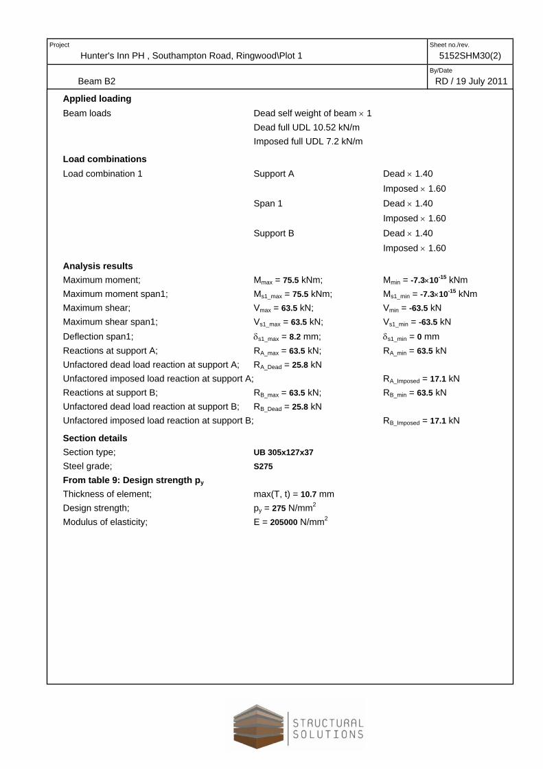
Applied loading Beam loads Dead self weight of beam × 1 Dead full UDL 10.52 kN/m Imposed full UDL 7.2 kN/m
Load combinations Load combination 1 Support A Dead × 1.40 Imposed × 1.60 Span 1 Dead × 1.40 Imposed × 1.60 Support B Dead × 1.40 Imposed × 1.60
Analysis results Maximum moment; Mmax = 75.5 kNm; Mmin = -7.3×10⁻¹⁵ kNm Maximum moment span1; Ms1_max = 75.5 kNm; Ms1_min = -7.3×10⁻¹⁵ kNm Maximum shear; Vmax = 63.5 kN; Vmin = -63.5 kN Maximum shear span1; Vs1_max = 63.5 kN; Vs1_min = -63.5 kN Deflection span1; δs1_max = 8.2 mm; δs1_min = 0 mm Reactions at support A; RA_max = 63.5 kN; RA_min = 63.5 kN Unfactored dead load reaction at support A; RA_Dead = 25.8 kN Unfactored imposed load reaction at support A; RA_Imposed = 17.1 kN Reactions at support B; RB_max = 63.5 kN; RB_min = 63.5 kN Unfactored dead load reaction at support B; RB_Dead = 25.8 kN Unfactored imposed load reaction at support B; RB_Imposed = 17.1 kN
Section details Section type; UB 305x127x37 Steel grade; S275 From table 9: Design strength py Thickness of element; max(T, t) = 10.7 mm Design strength; py = 275 N/mm2 Modulus of elasticity; E = 205000 N/mm2

Project
Hunter's Inn PH , Southampton Road, Ringwood\Plot1 Sheet no./rev.
5152SHM30(2)
Beam B2 By/Date
RD / 19 July 2011
123.4
7.1
Lateral restraint Span 1 has full lateral restraint
Effective length factors Effective length factor in major axis; Kx = 1.00 Effective length factor in minor axis; Ky = 1.00 Effective length factor for lateral-torsional buckling; KLT = 1.00;
Classification of cross sections - Section 3.5 ε = √[275 N/mm2 / py] = 1.00
Internal compression parts - Table 11 Depth of section; d = 265.2 mm d / t = 37.4 × ε <= 80 × ε; Class 1 plastic
Outstand flanges - Table 11 Width of section; b = B / 2 = 61.7 mm b / T = 5.8 × ε <= 9 × ε; Class 1 plastic
Section is class 1 plastic Shear capacity - Section 4.2.3 Design shear force; Fv = max(abs(Vmax), abs(Vmin)) = 63.5 kN d / t < 70 × ε
Web does not need to be checked for shear buckling Shear area; Av = t × D = 2161 mm2 Design shear resistance; Pv = 0.6 × py × Av = 356.6 kN
PASS - Design shear resistance exceeds design shear force Moment capacity - Section 4.2.5 Design bending moment; M = max(abs(Ms1_max), abs(Ms1_min)) = 75.5 kNm
Project
Hunter's Inn PH , Southampton Road, Ringwood\Plot 1 Sheet no./rev.
5152SHM30(2)
Beam B2 By/Date
RD / 19 July 2011
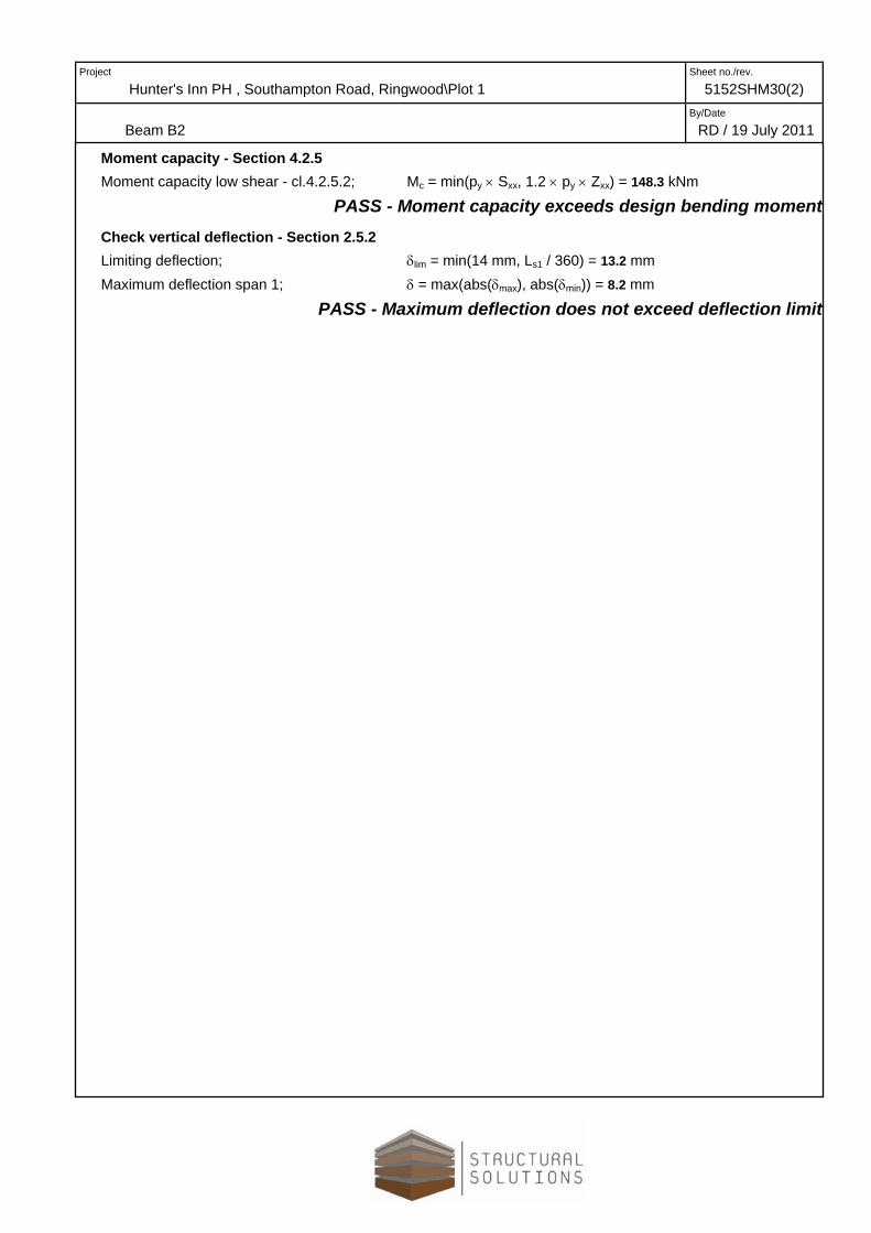
Moment capacity - Section 4.2.5 Moment capacity low shear - cl.4.2.5.2; Mc = min(py × Sxx, 1.2 × py × Zxx) = 148.3 kNm
PASS - Moment capacity exceeds design bending moment Check vertical deflection - Section 2.5.2 Limiting deflection;; δlim = min(14 mm, Ls1 / 360) = 13.2 mm Maximum deflection span 1; δ = max(abs(δmax), abs(δmin)) = 8.2 mm
PASS - Maximum deflection does not exceed deflection limit

Project
Hunter's Inn PH , Southampton Road, Ringwood\Plot 1 Sheet no./rev.
5152SHM30(2)
Beam B1 By/Date
RD / 19 July 2011
WallDead Live Dead Live Dead Dead Live Total
0-3 0-3 0.96 1.50 0.96 1.50 0.500.30 0.30 3.50 3.50 2.500.29 0.45 3.35 5.25 1.25 4.88 5.70 10.58
Second Floor First Floor Total LoadsStud Ref.
STEEL BEAM ANALYSIS & DESIGN (BS5950) TEDDS calculation version 1.0.03
Load Envelope - Combination 1
0.0
16.364
mm 47501A B
Support conditions Support A Vertically restrained Rotationally free Support B Vertically restrained Rotationally free

Project
Hunter's Inn PH , Southampton Road, Ringwood\Plot 1Sheet no./rev.
5152SHM30(2)
Beam B1 By/Date
RD / 19 July 2011
Applied loading Beam loads Dead self weight of beam × 1 Dead full UDL 4.88 kN/m Imposed full UDL 5.7 kN/m
Load combinations Load combination 1 Support A Dead × 1.40 Imposed × 1.60 Span 1 Dead × 1.40 Imposed × 1.60 Support B Dead × 1.40 Imposed × 1.60
Analysis results Maximum moment; Mmax = 46.2 kNm; Mmin = -3.6×10⁻¹⁵ kNm Maximum moment span1; Ms1_max = 46.2 kNm; Ms1_min = -3.6×10⁻¹⁵ kNm Maximum shear; Vmax = 38.9 kN; Vmin = -38.9 kN Maximum shear span1; Vs1_max = 38.9 kN; Vs1_min = -38.9 kN Deflection span1; δs1_max = 12.1 mm; δs1_min = 4.2×10⁻¹⁶ mm Reactions at support A; RA_max = 38.9 kN; RA_min = 38.9 kN Unfactored dead load reaction at support A; RA_Dead = 12.3 kN Unfactored imposed load reaction at support A; RA_Imposed = 13.5 kN Reactions at support B; RB_max = 38.9 kN; RB_min = 38.9 kN Unfactored dead load reaction at support B; RB_Dead = 12.3 kN Unfactored imposed load reaction at support B; RB_Imposed = 13.5 kN
Section details Section type; UB 203x133x30 Steel grade; S275 From table 9: Design strength py Thickness of element; max(T, t) = 9.6 mm Design strength; py = 275 N/mm2 Modulus of elasticity; E = 205000 N/mm2
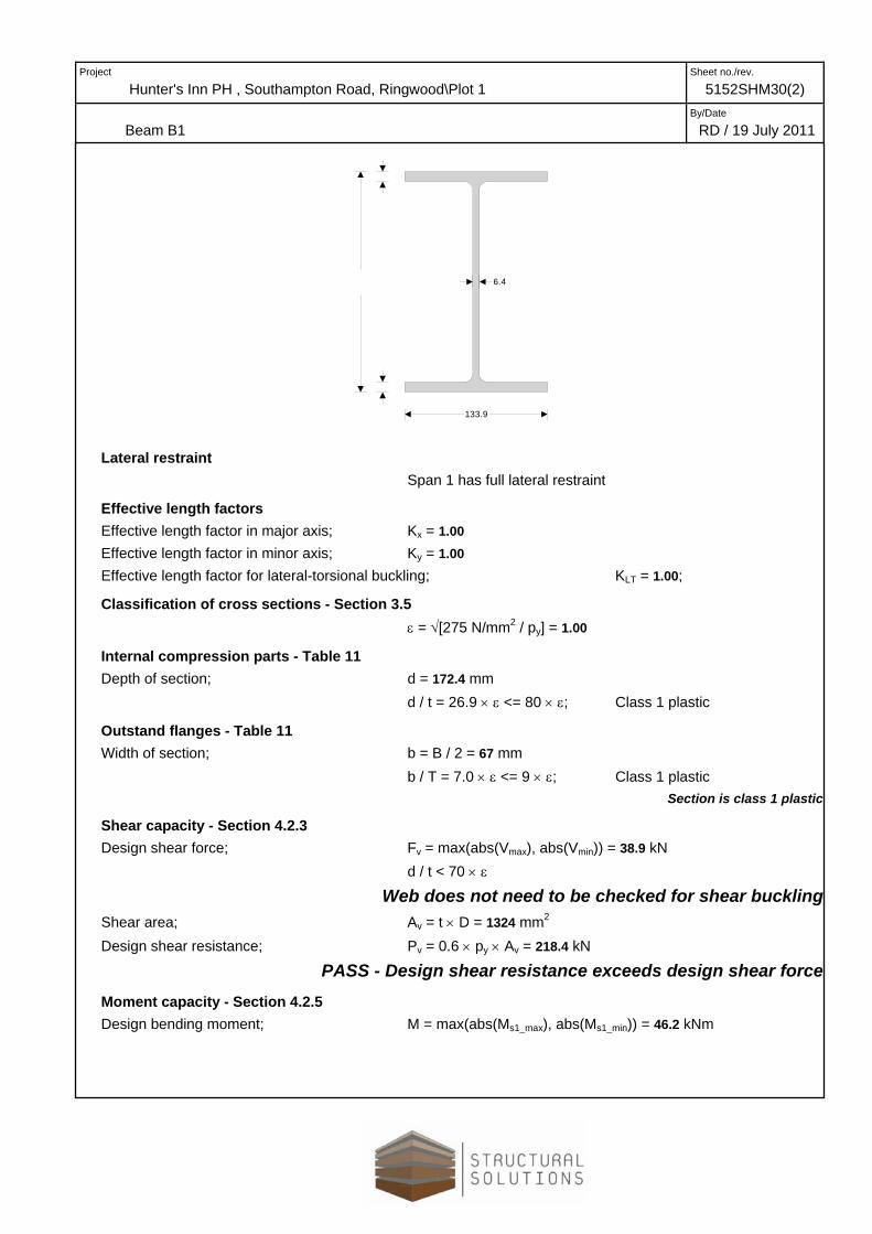
Project
Hunter's Inn PH , Southampton Road, Ringwood\Plot 1Sheet no./rev.
5152SHM30(2)
Beam B1 By/Date
RD / 19 July 2011
133.9
6.4
Lateral restraint Span 1 has full lateral restraint
Effective length factors Effective length factor in major axis; Kx = 1.00 Effective length factor in minor axis; Ky = 1.00 Effective length factor for lateral-torsional buckling; KLT = 1.00;
Classification of cross sections - Section 3.5 ε = √[275 N/mm2 / py] = 1.00
Internal compression parts - Table 11 Depth of section; d = 172.4 mm d / t = 26.9 × ε <= 80 × ε; Class 1 plastic
Outstand flanges - Table 11 Width of section; b = B / 2 = 67 mm b / T = 7.0 × ε <= 9 × ε; Class 1 plastic
Section is class 1 plastic Shear capacity - Section 4.2.3 Design shear force; Fv = max(abs(Vmax), abs(Vmin)) = 38.9 kN d / t < 70 × ε
Web does not need to be checked for shear buckling Shear area; Av = t × D = 1324 mm2 Design shear resistance; Pv = 0.6 × py × Av = 218.4 kN
PASS - Design shear resistance exceeds design shear force Moment capacity - Section 4.2.5 Design bending moment; M = max(abs(Ms1_max), abs(Ms1_min)) = 46.2 kNm

Project
Hunter's Inn PH , Southampton Road, Ringwood\Plot 1 Sheet no./rev.
5152SHM30(2)
Beam B1 By/Date
RD / 19 July 2011
Moment capacity - Section 4.2.5 Moment capacity low shear - cl.4.2.5.2; Mc = min(py × Sxx, 1.2 × py × Zxx) = 86.5 kNm
PASS - Moment capacity exceeds design bending moment Check vertical deflection - Section 2.5.2 Limiting deflection;; δlim = min(14 mm, Ls1 / 360) = 13.2 mm Maximum deflection span 1; δ = max(abs(δmax), abs(δmin)) = 12.1 mm
PASS - Maximum deflection does not exceed deflection limit