PLEASE READ ALL DIRECTIONS BEFORE STARTING …2015 2KK K K aaawskaiVukllcnSiVwukl 2015 Kawasaki...
7
17-061 www.powercommander.com 2015 Kawasaki Vulcan S - PCV F/I - 1 PARTS LIST 1 Power Commander 1 USB Cable 1 Installation Guide 2 Power Commander Decals 2 Dynojet Decals 2 Velcro strips 1 Alcohol swab 1 O2 Optimizer THE LATEST POWER COMMANDER SOFTWARE AND MAP FILES CAN BE DOWNLOADED FROM OUR WEB SITE AT: www.powercommander.com 2015 Kawasaki Vulcan S Installation Instructions PLEASE READ ALL DIRECTIONS BEFORE STARTING INSTALLATION THE IGNITION MUST BE TURNED OFF BEFORE INSTALLATION! 2191 Mendenhall Drive North Las Vegas, NV 89081 (800) 992-4993 www.powercommander.com FUEL AND IGNITION
Transcript of PLEASE READ ALL DIRECTIONS BEFORE STARTING …2015 2KK K K aaawskaiVukllcnSiVwukl 2015 Kawasaki...

17-061 www.powercommander.com 2015 Kawasaki Vulcan S - PCV F/I - 1
PARTS LIST
1 PowerCommander1 USBCable1 InstallationGuide2 PowerCommanderDecals2 DynojetDecals2 Velcrostrips1 Alcoholswab1 O2Optimizer
THE LATEST POWER COMMANDER SOFTWARE AND MAP FILES CAN BE
DOWNLOADED FROM OUR WEB SITE AT:www.powercommander.com
2015 Kawasaki Vulcan S
I ns ta l l a t i on I ns t ruc t i ons
PLEASE READ ALL DIRECTIONS BEFORE STARTING INSTALLATION
THE IGNITION MUST BE TURNED OFF BEFORE INSTALLATION!
2191 Mendenhall Drive North Las Vegas, NV 89081 (800) 992-4993 www.powercommander.com
FUEL AND IGNITION

17-061 www.powercommander.com 2015 Kawasaki Vulcan S - PCV F/I - 2
EXPANSION PORTS 1 & 2
OptionalAccessoriessuchasPOD-300unitorAuto-tunekit.
POWER COMMANDER V INPUT ACCESSORY GUIDE
Map - (Input1or2)ThePCVhastheabilitytohold2differentbasemaps.YoucanswitchontheflybetweenthesetwobasemapswhenyouhookupaswitchtotheMAPinputs.Youcanuseanyopen/closetypeswitch.Thepolarityofthewiresisnotimportant.WhenusingtheAutotunekitonepositionwillholdabasemapandtheotherpositionwillletyouactivatethelearningmode.Whentheswitchis“CLOSED”Autotunewillbeactivated.(SettoSwitchInput#1bydefault.)
Shifter- (Input1or2)TheseinputsareforusewiththeDynojetquickshifter.InsertthewiresfromtheDynojetquickshifterintotheSHIFTERinputs.Thepolarityofthewiresisnotimportant.(SettoSwitchInput#2bydefault.)
Speed- Ifyourapplicationhasaspeedsensorthenyoucantapintothesignalsideofthesensorandrunawireintothisinput.ThiswillallowyoutocalculategearpositionintheControlCenterSoftware.Oncegearpositionissetupyoucanalteryourmapbasedongearpositionandsetupgeardependentkilltimeswhenusingaquickshifter.
Analog- Thisinputisfora0-5vsignalsuchasenginetemp,boost,etc.Oncethisinputisestablishedyoucanalteryourfuelcurvebasedonthisinputinthecontrolcentersoftware.
Crank- DoNOTconnectanythingtothisportunlessinstructedtodosobyDynojet.Itisusedtotransfercranktriggerdatafromonemoduletoanother.
ACCESSORY INPUTS
Wire connections:
ToinputwiresintothePCVfirstremovetherubberplugonthebacksideoftheunitandloosenthescrewforthecorrespondinginput.Usinga22-24gaugewirestripabout10mmfromitsend.PushthewireintotheholeofthePCVuntilisstopsandthentightenthescrew.Makesuretoreinstalltherubberplug.
NOTE:Ifyoutinthewireswithsolderitwillmakeinsertingthemeasier.
CRANK
ANALOG
SPEED
INPUT 1 (Grnd)
INPUT 1
INPUT 2 (Grnd)
INPUT 2
USB CONNECTION

17-061 www.powercommander.com 2015 Kawasaki Vulcan S - PCV F/I - 3
1 Removetheseat,theleftsidepanel,thekeyswitchcover.Removetheleftandrightsidekneepanels(Fig.A).
2 Removetherightsidecoverlocatedrearoftheengine.Removetherightsideradiatorsidecover.
3 Removethefueltank(Fig.B).
4 RemovetheECUandloosenthestockwiringfromtheairbox.Removetheairbox(Fig.C).
FIG.A
FIG.C
FIG.B
Remove
RemoveRemove
Remove
Remove
Remove
Remove
Remove
Remove

17-061 www.powercommander.com 2015 Kawasaki Vulcan S - PCV F/I - 4
5 StorethePCVmoduleundertheseat,justrearofthebattery(Fig.D).ThesuppliedVelcrocanbeusedtosecurethemodule.CleanbothsurfaceswiththesuppliedalcoholswabpriortoapplyingtheVelcroadhesive.
6 SecurethePCVgroundwirewiththesmallringlugtothenegative(-)terminalofthebike’sbattery.
7 RoutethePCVwiringharnessforwardtowardstheengine.
8 Attherearofthethrottlebodies,unplugbothfuelinjectors(Fig.E).
9 PlugthepairofPCVleadswithORANGEcoloredwiresin-lineoftheLEFTfuelinjectorandthestockwiringharness.
10 PlugthepairofPCVleadswithYELLOWcoloredwiresin-lineoftheRIGHTfuelinjectorandthestockwiringharness(Fig.F).
FIG.D
FIG.F
FIG.E
GroundUn
plug
Unpl
ug

17-061 www.powercommander.com 2015 Kawasaki Vulcan S - PCV F/I - 5
11 Ontheleftsideofthethrottlebodies,unplugthelowerprimaryThrottlePositionSensorwiththestockGREYconnector(Fig.G).
12 PlugthePCVwiringharnessin-lineofthelowerprimaryThrottlePositionSensorandthestockwiringharness(Fig.H).
13 Unplugthestockwiringharnessfrombothignitioncoilsatthetopoftheengine(Fig.J).
FIG.FIG.G
FIG.H
FIG.J
Unplug
Unpl
ug Unplug

17-061 www.powercommander.com 2015 Kawasaki Vulcan S - PCV F/I - 6
14 PlugthepairofPCVleadswithGREENcoloredwiresin-lineoftheLEFTIgnitionCoilandthestockwiringharness.
15 PlugthepairofPCVleadswithBLUEcoloredwiresin-lineoftheRIGHTIgnitionCoilandthestockwiringharness(Fig.K).
FIG.K
FIG.M
FIG.L
17 PlugthepairofPCVleadswithBROWNcoloredwiresin-lineofthestockCrankPositionSensorconnectors(Fig.M).
16 UnplugthestockCrankPositionSensorconnectorslocatedontherightsideofthebikeneartheradiatorcap(Fig.L).
Unplug
17-061 www.powercommander.com 2015 Kawasaki Vulcan S - PCV F/I - 7
18 UnplugthestockO2sensorconnectors.Thisconnectionislocatedontherightsideofthebikejustrearoftheengine,behindthecoverremovedpreviouslyinStep2.
FIG.N
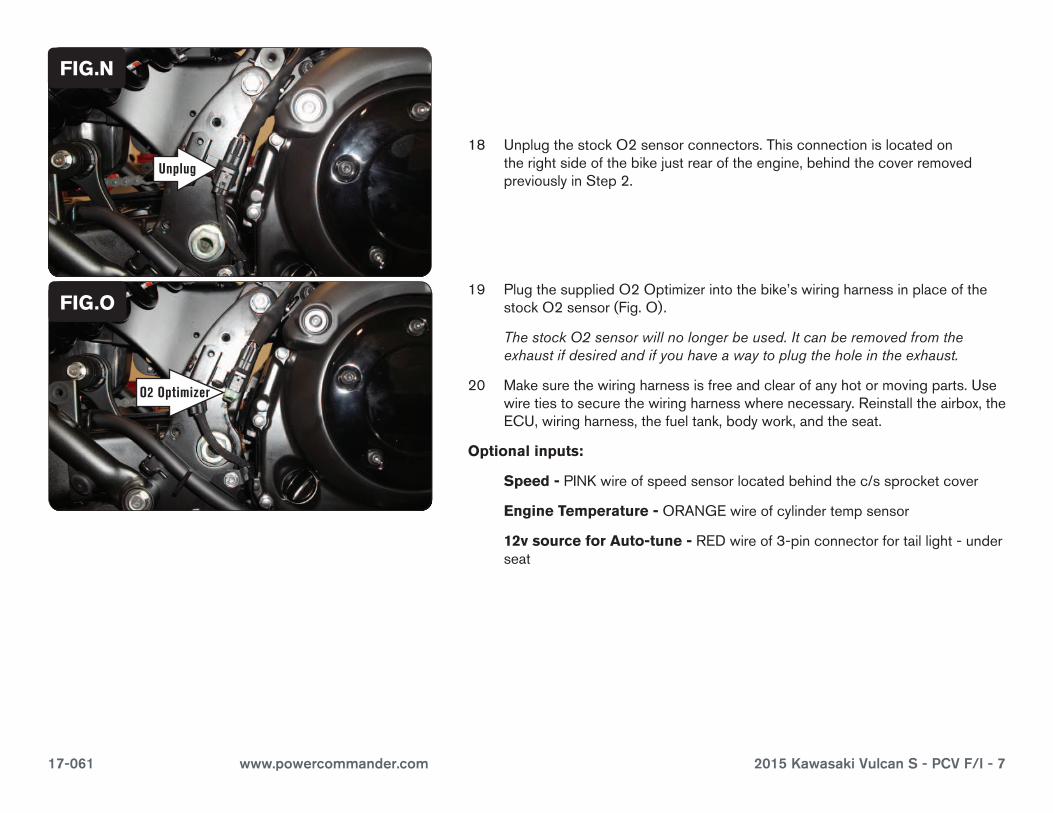
FIG.O19 PlugthesuppliedO2Optimizerintothebike’swiringharnessinplaceofthe
stockO2sensor(Fig.O).
The stock O2 sensor will no longer be used. It can be removed from the exhaust if desired and if you have a way to plug the hole in the exhaust.
20 Makesurethewiringharnessisfreeandclearofanyhotormovingparts.Usewiretiestosecurethewiringharnesswherenecessary.Reinstalltheairbox,theECU,wiringharness,thefueltank,bodywork,andtheseat.
Optional inputs:
Speed -PINKwireofspeedsensorlocatedbehindthec/ssprocketcover
Engine Temperature -ORANGEwireofcylindertempsensor
12v source for Auto-tune -REDwireof3-pinconnectorfortaillight-underseat
Unplug
O2 Optimizer