Plc & scada report 4
110
A SUMMER TRAINING REPORT ON “Automation using PLC and SCADA” Submitte d in partial fulfillment for bachelor of technology degree at Rajasthan Technical University, Kota 1
-
Upload
lakshminarayan-solanki -
Category
Engineering
-
view
126 -
download
13
Transcript of Plc & scada report 4

A SUMMER TRAINING REPORT ON
“Automation using PLC and SCADA”
Submitted in partial fulfillment for bachelor of
technology degree at
Rajasthan Technical University, Kota
(2015-16)
Submitted to: Submitted by:
Prof. Manish Bhati Pradeep Solanki
1

Prof. Hanuman Patel B.TECH 4th YEAR
Department of Electrical Engineering
VYAS INSTITUTE OF ENGINEERING AND TECHNOLOGY, JODHPUR (Raj.)
VYAS INSTITUTE OF ENGINEERING AND TECHNOLOGY,
JODHPUR (RAJ.)
DEPARTMENT OF ELECTRICAL ENGINEERING
CERTIFICATE
This is to certify that the student PRADEEP SOLANKI of final year, have
Successfully completed the summer training report on titled “Automation
using PLC and SCADA” towards the partial fulfillment of the degree of
Bachelor of Technology (B.TECH). In the Electrical Engineering of the
Rajasthan Technical University during academic year 2015-16.
2

Guided By Head of the Department Prof. Hanuman Patel Prof. Manish Bhati Prof. S.K. Joshi
ACKNOWLEDGMENT
I can’t achieve worthwhile in the field of the technical education without
testing the theoretical knowledge acquired in classroom as it is effectively
linked to the practical approach. I am experiencing the same in the
training program.
I would like to express a deep sense of gratitude and thanks profusely to
Mr. Yash Sharma, whose excellent guidance, constant encouragement
and motivation has inspired me a lot at all phases of my training, in class
as well as in the lab, without whom i would not be able to understand the
pointers and concepts of PLC PROGRAMMING. I am also extremely
thankful to the lab technicians for guiding and helping us during the lab
practices. Finally, I also express my gratitude to other faculty members of
MERC for their intellectual support throughout the course of PLC
PROGRAMMING. It is a wonderful experience and I am deeply thankful
to all the staff of MERC.
Pradeep Solanki
B.TECH 4rh YEAR
3

ELECTRICAL ENGINEERING
ABSTRACT
Industrial training is must for the every student perusing professional degree because
the ultimate goal of every student is to get the information the industrial training helps
us to get an idea of the things.
We should know in order to get a good job i.e. I have a good professional career.
Industrial training teaches us lots of things. It helps us to know the kind of
environment we would be getting in the industry and help us to get with the kind of
environment. The totality the industrial teaches us industrial ethics. Some advance
technical knowledge how and help us to acquire with industrial working style.
Supervisory control and data acquisition (SCADA) allows a utility operator to
monitor and control processes that are distributed among various remote sites.
SCADA is a system for gathering real time data, controlling processes, and
monitoring equipment from remote locations. As more companies are implementing
an open SCADA architecture through the Internet to monitor critical infrastructure
components such as power plants, oil and gas pipelines, chemical refineries, flood
control dams, and waste and water systems, vital systems are becoming increasingly
open to attack. This report provides an overview of SCADA, outlines several
vulnerabilities of SCADA systems, presents data on known and possible threats, and
provides particular remediation strategies for protecting these systems.
PLCs are used in many different industries and machines such as packaging and
semiconductor machines. Programs to control machine operation are typically stored
in battery-backed or non-volatile memory. A programmable logic controller (PLC) or
programmable controller is a digital computer used for automation of
4

electromechanical processes, such as control of machinery on factory assembly lines,
amusement rides, or lighting fixtures. PLCs are used in many industries and
machines. Unlike general-purpose computers, the PLC is designed for multiple inputs
and output arrangements, extended temperature ranges, immunity to electrical noise,
and resistance to vibration and impact.
CONTENT
CHAPTER 1-AUTOMATION……………………………….………6
CHAPTER 2 SUPERVISORY CONTROL AND DATA ACQUISITION…………………………………………….…………13
CHAPTER 3 CONTROLLERS ………………………….………20
CHAPTER 4 PROGRAMABLE LOGIC CONTROLLER…..……….26
CHAPTER 5 ALLEN BRADLY PLC …………………………….....32
CHAPTER 6 SIEMENS PLC …….…………….……………………..42
CHAPTER 7 DRIVES …………….………...…………………...……48
5

CHAPTER 8 CONCLUSION……..……….……….……………….....60
Chapter-1
Automation
Automation or automatic control is the use of various control systems for operating equipment such as machinery, processes in factories, boilers and heat treating ovens, switching in telephone networks, steering and stabilization of ships, aircraft and other applications with minimal or reduced human intervention. Some processes have been completely automated.
The biggest benefit of automation is that it saves labors; however, it is also used to save energy and materials and to improve quality, accuracy and precision.
The term automation, inspired by the earlier word automatic (coming from automaton), was not widely used before 1947, when General Motors established the automation department .It was during this time that industry was rapidly adopting feedback controllers, which were introduced in the 1930s.
Automation has been achieved by various means including mechanical, hydraulic, pneumatic, electrical, electronic and computers, usually in combination. Complicated systems, such as modern factories, airplanes and ships typically use all these combined techniques.
1.1 Types of automation
Main article: Control system
Two common types of automation are feedback control, which is usually continuous and involves taking measurements using a sensor and making calculated adjustments to keep the measured variable within a set range, and sequence control, in which a programmed sequence of discrete operations is performed, often based on system
6

logic. Cruise control is an example of the former while an elevator or an automated teller machine (ATM) is an example of the latter.
The theoretical basis of feedback control is control theory, which also covers servomechanisms, which are often part of an automated system. Feedback control is called "closed loop" while non-feedback control is called "open loop."
1.1.1 Feedback control
Feedback control is accomplished with a controller. To function properly, a controller must provide correction in a manner that maintains stability. Maintaining stability is a principal objective of control theory.
As an example of feedback control, consider a steam coil air heater in which a temperature sensor measures the temperature of the heated air, which is the measured variable. This signal is constantly "fed back" to the controller, which compares it to the desired setting (set point). The controller calculates the difference (error), then calculates a correction and sends the correction signal to adjust the air pressure to a diaphragm that moves a positioner on the steam valve, opening or closing it by the calculated amount. All the elements constituting the measurement and control of a single variable are called a control loop.
The complexities of this are that the quantities involved are all of different physical types; the temperature sensor signal may be electrical or pressure from an enclosed fluid, the controller may employ pneumatic, hydraulic, mechanical or electronic techniques to sense the error and send a signal to adjust the air pressure that moves the valve.
The first controllers used analog methods to perform their calculations. Analog methods were also used in solving differential equations of control theory. The electronic analog computer was developed to solve control type problems and electronic analog controllers were also developed .Analog computers were displaced by digital computers when they became widely available.
Common applications of feedback control are control of temperature, pressure, flow, and speed.
1.1.2 Sequential control and logical sequence control
Sequential control may be either to a fixed sequence or to a logical one that will perform different actions depending on various system states. An example of an adjustable but otherwise fixed sequence is a timer on a lawn sprinkler. An elevator is an example that uses logic based on the system states to perform certain actions in response to operator input.
A development of sequential control was relay logic, by which electrical relays engage electrical contacts which either start or interrupt power to a device. Relays were first used in telegraph networks before being developed for controlling other devices, such as when starting and stopping industrial-sized electric motors or opening and closing solenoid valves. Using relays for control purposes allowed event-driven control, where actions could be triggered out of sequence, in response to external events. These were more flexible in their response than the rigid single-
7

sequence cam timers. More complicated examples involved maintaining safe sequences for devices such as swing bridge controls, where a lock bolt needed to be disengaged before the bridge could be moved, and the lock bolt could not be released until the safety gates had already been closed.
The total number of relays, cam timers and drum sequencers can number into the hundreds or even thousands in some factories. Early programming techniques and languages were needed to make such systems manageable, one of the first being ladder logic, where diagrams of the interconnected relays resembled the rungs of a ladder. Special computers called programmable logic controllers were later designed to replace these collections of hardware with a single, more easily re-programmed unit.
In a typical hard wired motor start and stop circuit (called a control circuit) a motor is started by pushing a "Start" or "Run" button that activates a pair of electrical relays. The "lock-in" relay locks in contacts that keep the control circuit energized when the push button is released. (The start button is a normally open contact and the stop button is normally closed contact.) Another relay energizes a switch that powers the device that throws the motor starter switch (three sets of contacts for three phase industrial power) in the main power circuit. (Note: Large motors use high voltage and experience high in-rush current, making speed important in making and breaking contact. This can be dangerous for personnel and property with manual switches.) All contacts are held engaged by their respective electromagnets until a "stop" or "off" button is pressed, which de-energizes the lock in relay. See diagram: Motor Starters Hand-Off-Auto With Start-Stop (Note: The above description is the "Auto" position case in this diagram).
Commonly interlocks are added to a control circuit. Suppose that the motor in the example is powering machinery that has a critical need for lubrication. In this case an interlock could be added to insure that the oil pump is running before the motor starts. Timers, limit switches and electric eyes are other common elements in control circuits.
Solenoid valves are widely used on compressed air or hydraulic fluid for powering actuators on mechanical components. While motors are used to supply continuous rotary motion, actuators are typically a better choice for intermittently creating a limited range of movement for a mechanical component, such as moving various mechanical arms, opening or closing valves, raising heavy press rolls, applying pressure to presses.
1.1.3 Computer control
Computers can perform both sequential control and feedback control, and typically a single computer will do both in an industrial application. Programmable logic controllers (PLCs) are a type of special purpose microprocessor that replaced many hardware components such as timers and drum sequencers used in relay logic. General purpose process control computers have increasingly replaced stand alone controllers, with a single computer able to perform the operations of hundreds of controllers. Process control computers can process data from a network of PLCs, instruments and controllers in order to implement typical (such as PID) control of many individual variables or, in some cases, to implement complex control algorithms using multiple inputs and mathematical manipulations. They can also analyze data
8

and create real time graphical displays for operators and run reports for engineers and management.
Control of an automated teller machine (ATM) is an example of an interactive process in which a computer will perform a logic derived response to a user selection based on information retrieved from a networked database. The ATM process has a lot of similarities to other online transaction processes. The different logical responses are called scenarios. Such processes are typically designed with the aid of use cases and flowcharts, which guide the writing of the software code.
1.2 History
The earliest feedback control mechanism was used to tent the sails of windmills. It was patented by Edmund Lee in 1745.
The centrifugal governor, which dates to the last quarter of the 18th century, was used to adjust the gap between millstones. The centrifugal governor was also used in the automatic flour mill developed by Oliver Evans in 1785, making it the first completely automated industrial process. The governor was adopted by James Watt for use on a steam engine in 1788 after Watt’s partner Boulton saw one at a flour mill Boulton & Watt were building.
The governor could not actually hold a set speed; the engine would assume a new constant speed in response to load changes. The governor was able to handle smaller variations such as those caused by fluctuating heat load to the boiler. Also, there was a tendency for oscillation whenever there was a speed change. As a consequence, engines equipped with this governor were not suitable for operations requiring constant speed, such as cotton spinning.
Several improvements to the governor, plus improvements to valve cut-off timing on the steam engine, made the engine suitable for most industrial uses before the end of the 19th century. Advances in the steam engine stayed well ahead of science, both thermodynamics and control theory.
The governor received relatively little scientific attention until James Clerk Maxwell published a paper that established the beginning of a theoretical basis for understanding control theory. Development of the electronic amplifier during the 1920s, which was important for long distance telephony, required a higher signal to noise ratio, which was solved by negative feedback noise cancellation. This and other telephony applications contributed to control theory. Military applications during the Second World War that contributed to and benefited from control theory were fire-control systems and aircraft controls. The so-called classical theoretical treatment of control theory dates to the 1940s and 1950s.
Relay logic was introduced with factory electrification, which underwent rapid adaption from 1900 though the 1920s. Central electric power stations were also undergoing rapid growth and operation of new high pressure boilers, steam turbines and electrical substations created a large demand for instruments and controls.
Central control rooms became common in the 1920s, but as late as the early 1930s, most process control was on-off. Operators typically monitored charts drawn by recorders that plotted data from instruments. To make corrections,operators manually
9

opened or closed valves or turned switches on or off. Control rooms also used color coded lights to send signals to workers in the plant to manually make certain changes.
Controllers, which were able to make calculated changes in response to deviations from a set point rather than on-off control, began being introduced the 1930s. Controllers allowed manufacturing to continue showing productivity gains to offset the declining influence of factory electrification.
In 1959 Texaco’s Port Arthur refinery became the first chemical plant to use digital control. Conversion of factories to digital control began to spread rapidly in the 1970s as the price of computer hardware fell.
1.3 Significant applications
The automatic telephone switchboard was introduced in 1892 along with dial telephones. By 1929, 31.9% of the Bell system was automatic. Automatic telephone switching originally used electro-mechanical switches, which consumed a large amount of electricity. Call volume eventually grew so fast that it was feared the telephone system would consume all electricity production, prompting Bell Labs to begin research on the transistor.
The logic performed by telephone switching relays was the inspiration for the digital computer.
The first commercially successful glass bottle blowing machine was an automatic model introduced in 1905. The machine, operated by a two man crew working 12 hour shifts, could produce 17,280 bottles in 24 hours, compared to 2,880 bottles made by a crew of six men and boys working in a shop for a day. The cost of making bottles by machine was 10 to 12 cents per gross compared to $1.80 per gross by the manual glassblowers and helpers.
Sectional electric drives were developed using control theory. Sectional electric drives are used on different sections of a machine where a precise differential must be maintained between the sections. In steel rolling, the metal elongates as it passes through pairs of rollers, which must run at successively faster speeds. In paper making the paper sheet shrinks as it passes around steam heated drying arranged in groups, which must run at successively slower speeds. The first application of a sectional electric drive was on a paper machine in 1919. One of the most important developments in the steel industry during the 20th century was continuous wide strip rolling, developed by Armco in 1928.
Before automation many chemicals were made in batches. In 1930, with the widespread use of instruments and the emerging use of controllers, the founder of Dow Chemical Co. was advocating continuous production.
Self-acting machine tools that displaced hand dexterity so they could be operated by boys and unskilled laborers were developed by James Nasmyth in the 1840s.Machine tools were automated with Numerical control (NC) using punched paper tape in the 1950s. This soon evolved into computerized numerical control (CNC).
Today extensive automation is practiced in practically type of manufacturing and assembly process. Some of the larger processes include electrical power generation,
10

oil refining, chemicals, steel mills, plastics, cement plants, fertilizer plants, pulp and paper mills, automobile and truck assembly, aircraft production, glass manufacturing, natural gas separation plants, food and beverage processing, canning and bottling and manufacture of various kinds of parts. Robots are especially useful in hazardous applications like automobile spray painting. Robots are also used to assemble electronic circuit boards. Automotive welding is done with robots and automatic welders are used in applications like pipelines.
1.4 Advantages and disadvantages
The main advantages of automation are:
Increased through output or productivity. Improved quality or increased predictability of quality. Improved robustness (consistency), of processes or product. Increased consistency of output. Reduced direct human labor costs and expenses.
The following methods are often employed to improve productivity, quality, or robustness.
Install automation in operations to reduce cycle time. Install automation where a high degree of accuracy is required. Replacing human operators in tasks that involve hard physical or monotonous
work.]
Replacing humans in tasks done in dangerous environments (i.e. fire, space, volcanoes, nuclear facilities, underwater, etc.)
Performing tasks that are beyond human capabilities of size, weight, speed, endurance, etc.
Economic improvement: Automation may improve in economy of enterprises, society or most of humanity. For example, when an enterprise invests in automation, technology recovers its investment; or when a state or country increases its income due to automation like Germany or Japan in the 20th Century.
Reduces operation time and work handling time significantly. Frees up workers to take on other roles. Provides higher level jobs in the development, deployment, maintenance and
running of the automated processes.
The main disadvantages of automation are:
Causing unemployment and poverty by replacing human labor. Security Threats/Vulnerability: An automated system may have a limited level
of intelligence, and is therefore more susceptible to committing errors outside of its immediate scope of knowledge (e.g., it is typically unable to apply the rules of simple logic to general propositions).
Unpredictable/excessive development costs: The research and development cost of automating a process may exceed the cost saved by the automation itself.
High initial cost: The automation of a new product or plant typically requires a very large initial investment in comparison with the unit cost of the product,
11

although the cost of automation may be spread among many products and over time. In manufacturing, the purpose of automation has shifted to issues broader than productivity, cost, and time.
1.5 Health and environment
The costs of automation to the environment are different depending on the technology, product or engine automated. There are automated engines that consume more energy resources from the Earth in comparison with previous engines and those that do the opposite too. Hazardous operations, such as oil refining, the manufacturing of industrial chemicals, and all forms of metal working, were always early contenders for automation.
1.6 Convertibility and turnaround time
Another major shift in automation is the increased demand for flexibility and convertibility in manufacturing processes. Manufacturers are increasingly demanding the ability to easily switch from manufacturing Product A to manufacturing Product B without having to completely rebuild the production lines. Flexibility and distributed processes have led to the introduction of Automated Guided Vehicles with Natural Features Navigation.
Digital electronics helped too. Former analogue-based instrumentation was replaced by digital equivalents which can be more accurate and flexible, and offer greater scope for more sophisticated configuration, parameterization and operation. This was accompanied by the field bus revolution which provided a networked (i.e. a single cable) means of communicating between control systems and field level instrumentation, eliminating hard-wiring.
Discrete manufacturing plants adopted these technologies fast. The more conservative process industries with their longer plant life cycles have been slower to adopt and analogue-based measurement and control still dominates. The growing use of Industrial Ethernet on the factory floor is pushing these trends still further, enabling manufacturing plants to be integrated more tightly within the enterprise, via the internet if necessary. Global competition has also increased demand for Reconfigurable Manufacturing Systems.
1.7 Automation tools
Engineers can now have numerical control over automated devices. The result has been a rapidly expanding range of applications and human activities. Computer-aided technologies (or CAx) now serve the basis for mathematical and organizational tools used to create complex systems. Notable examples of CAx include Computer-aided design (CAD software) and Computer-aided manufacturing (CAM software). The improved design, analysis, and manufacture of products enabled by CAx has been beneficial for industry.
Information technology, together with industrial machinery and processes, can assist in the design, implementation, and monitoring of control systems. One example of an industrial control system is a programmable logic controller (PLC). PLCs are specialized hardened computers which are frequently used to synchronize the flow of
12

inputs from (physical) sensors and events with the flow of outputs to actuators and events.
Chapter – 2
SUPERVISORY CONTROL AND DATA ACQUISITION (SCADA)
2.1 WHAT IS MEANT BY SCADA?
SCADA stands for supervisory control and data acquisition. As the name indicates it
is not a full control system, but rather focuses on the supervisory level. As such , it is
a purely software package that is positioned on the top of hardware to which it is
interfaced in general via programmable logic controllers (PLC’s ), or other
commercial hardware modules.
S- Supervisory (we can see process on monitor)
C- Control (when setup is complete we can also control the process )
A- And
D- Data (database can also be saved in plc or pc memory)
A- Acquisition
SCADA programs are used in industrial process control applications for centralized
monitoring and recording of pumps, tank levels, switches, temperatures etc. SCADA
13

systems are also referred to as HMI (Human Machine Interfaces), or the less
politically correct MMI (Man Machine Interfaces).
A SCADA program normally runs on a PC and communicates with external
instrumentation and control devices. Communications methods can be via direct serial
link, radio, modem, field bus or Ethernet links. If a mixture of instruments with
differing communication interfaces and protocols need to be connected, then
converters can be used. SCADA is often used on remote data acquisition systems
where the data is viewed and recorded centrally.
It’s an optional device used in automation for continuous monitoring.
Figure 2.1
14
Field Instruments
(Sensors, Transducers, Pressure Tx, Density Tx,
Thermocouples, Thermistors, LVDT)
Controllers
(PLC, DCS.CNC, PC Based)
SCADA
(For continuous monitoring)
Field Devices
(Motors, Heaters)

The SCADA program has a user configured database which tells the software about
the connected instrumentation and which parameters within the instruments are to be
accessed. The database may also hold information on how often the parameters of the
instruments are accessed and if a parameter is a read only value (e.g. a measured
value) or read / write, allowing the operator to change a value (e.g. an alarm set
point).
The parameters of the instrument being accessed are normally split between analogue
(numeric) and logic (digital). When running, the SCADA software continuously
updates its own database with the latest analogue and digital values collected from the
instrumentation. Some SCADA systems also allow real time calculations to be made
on the received data and the results would be available as a "virtual" value. The real
time values can then be used by the SCADA.
2.2 COMMUNICATIONS
2.2.1 INTERNAL COMMUNICATION
Server-client and server-server communication is in general on a publish-
subscribe and event-driven basis and uses a TCP/IP protocol, i.e., a client
application subscribes to a parameter which is owned by a particular server
application and only changes to that parameter are then communicated to the client
application.
2.2.2 ACCESS TO DEVICES
The data servers poll the controllers at a user defined polling rate. The polling rate
may be different for different parameters. The controllers pass the requested
parameters to the data servers. Time stamping of the process parameters is
typically performed in the controllers and this time-stamp is taken over by the
data server.
If the controller and communication protocol used support unsolicited data
transfer then the products will support this too. The products provide
communication drivers for most of the common PLCs and widely used field-buses,
e.g., Mod bus. Of the three field buses that are recommended at CERN, both Profibus
and Worldfip are supported but CAN bus often not. Some of the drivers are based on
third party products and therefore have additional cost associated with them. VME on
the other hand is generally not supported.
15

2.3 FUNCTIONALITY
2.3.1 ACCESS CONTROL
Users are allocated to groups, which have defined read/write access privileges
to the process parameters in the system and often also to specific product
functionality.
2.3.2 TRENDING
The products all provide trending facilities and one can summarize the
common capabilities as follows:
1) the parameters to be trended in a specific chart can be predefined or defined online
2) A chart may contain more than 8 trended parameters or pens and an
unlimited number of charts can be displayed (restricted only by the readability)
3) Real-time and historical trending are possible, although generally not in the same
chart
Figure 2.2
4) Historical trending is possible for any archived parameter
5) Zooming and scrolling functions are provided
6) Parameter values at the cursor position can be displayed
The trending feature is either provided as a separate module or as a graphical
object (ActiveX), which can then be embedded into a synoptic display. XY and other
16

statistical analysis plots are generally not provided.
2.3.3 ALARM HANDLING
Alarm handling is based on limit and status checking and performed in the data
servers. More complicated expressions (using arithmetic or logical expressions) can
be developed by creating derived parameters on which status or limit checking is then
performed. The alarms are logically handled centrally i.e., the information only
exists in one place and all users see the same status (e.g., the
acknowledgement), and multiple alarm priority levels (in general many more than 3
such levels) are supported.
Figure 1.3
2.3.4 LOGGING AND ARCHIVING
The terms logging and archiving are often used to describe the same facility.
However, logging can be thought of as medium-term storage of data on disk, whereas
archiving is long-term storage of data either on disk or on another permanent
storage medium. Logging is typically performed on a cyclic basis, i.e., once a certain
file size, time period or number of points is reached the data is overwritten. Logging
of data can be performed at a set frequency, or only initiated if the value
changes or when a specific predefined event occurs. Logged data can be
transferred to an archive once the log is full.
17

Figure 2.2
The Logged data is time-stamped and can be filtered when viewed by a user. The
logging of user actions is in general performed together with either a user ID or
station ID. There is often also a VCR facility to play back archived data.
2.3.5 NETWORKING
1. In many applications, we have to use more than one SCADA software /
operator stations. This can be achieved by taking the SCADA node on
network.
2. In many cases Ethernet TCP/IP is commonly used for networking.
3. In certain cases the SCADA software use propriety networking protocols for
networking.
2.3.6 DEVICE CONNECTIVITY
1. Every control hardware has its own communication protocol for
communicating with different hardware / software. Some of the leading
communication protocol include Modbus, Profibus, Ethernet, Dh +, DH 485,
Device net, Control net.
2. The SCADA software needs device driver software for communication with
PLC or other control hardware.
3. More the driver software available better is the device connectivity. Most of
the SCADA software used in the industry have connectivity with most of the
18

leading control system.
2.3.7 DATABASE CONNECTIVITY
1. In many plants, it is important to download the real-time information to the
MIS. In this case the database connectivity is must.
2. Many SCADA software don’t have their own database. Hence for storage and
reporting they use third party database like MS Access or SQL.
2.3.8 SCRIPT
1. Script is a way of writing logic in SCADA software. Every SCADA software
has its own instructions and way of writing program.
2. Using scripts, one can develop complex applications. You can create your own
functions to suit the process requirement execution.
3. Various types of scripts make project execution simpler for programmer.
2.4 AUTOMATION AND SCADA
The majority of the products allow actions to be automatically triggered by
events. A scripting language provided by the SCADA products allows these actions
to be defined. In general, one can load a particular display, send an Email,
run a user defined application or script and write to the RTDB.
The concept of recipes is supported, whereby a particular system configuration
can be saved to a file and then re-loaded at a later date .Sequencing is also supported
whereby, as the name indicates, it is possible to execute a more complex sequence of
actions on one or more devices. Sequences may also react to external events. Some of
the products do support an expert system but none has the concept of a Finite
rate Machine (FSM).
2.5 APPLICATION DEVELOPMENT
19

2.5.1 CONFIGURATION
SCADA is not a specific technology, but a type of application. SCADA stands for
Supervisory Control and Data Acquisition — any application that gets data about a
system in order to control that system is a SCADA application.
A SCADA application has two elements:
1. The process/system/machinery you want to monitor a control — this can be a
power plant, a water system, a network, a system of traffic lights, or anything else.
2. A network of intelligent devices that interfaces with the first system through
sensors and control outputs. This network, which is the SCADA system, gives you
the ability to measure and control specific elements of the first system.
The development of the applications is typically done in two stages. First the
process parameters and associated information (e.g. relating to alarm conditions)
are defined through some sort of parameter definition template and then the
graphics, including trending and alarm displays are developed, and linked where
appropriate to the process parameters.
The products also provide an ASCII Export/Import facility for the
configuration data (parameter definitions), which enables large numbers of parameters
to be configured in a more efficient manner using an external editor such as Excel and
then importing the data into the configuration database.
On-line modifications to the configuration database and the graphics are generally
possible with the appropriate level of privileges.
2.5.2 DEVELOPMENT TOOLS
The following development tools are provided as standard:
1. A graphics editor, with standard drawing facilities including freehand, lines,
squares circles, etc. It is possible to import pictures in many formats as
well as using predefined symbols including e.g. trending charts, etc. A library of
generic symbols is provided that can be linked dynamically to variables and
animated as they change. It is also possible to create links between views so
as to ease navigation at run-time.
20

Figure 2.5
2. A data base configuration tool (usually through parameter templates). It is in
general possible to export data in ASCII files so as to be edited through an ASCII
editor or Excel.
3. A scripting language
4. An Application Program Interface (API) supporting C, C++, VB
5. A Driver Development Toolkit to develop drivers for hardware that is
not supported by the SCADA product.
2.6 APPLICATIONS OF SCADA
We can use SCADA to manage any kind of equipment. Typically, SCADA systems
are used to automate complex industrial processes where human control is impractical
— systems where there are more control factors, and more fast-moving control
factors, than human beings can comfortably manage.
Around the world, SCADA systems control.
2.6.1 ELECTRIC POWER GENERATION, TRANSMISSION AND
DISTRIBUTION
Electric utilities use SCADA systems to detect current flow and line voltage, to
monitor the operation of circuit breakers, and to take sections of the power grid online
or offline.
2.6.2 WATER AND SEWAGE
State and municipal water utilities use SCADA to monitor and regulate water flow,
reservoir levels, pipe pressure and other factors.
2.6.3 BUILDING, FACILITIES AND ENVIRONMENTFacility managers use SCADA to control HVAC, refrigeration units, lighting and
entry systems.
21

2.6.4 MANUFACTURING
SCADA systems manage parts inventories for just-in-time manufacturing, regulate
industrial automation and robots, and monitor process and quality control.
2.6.5 MASS TRANSIT
Transit authorities use SCADA to regulate electricity to subways, trams and trolley
buses; to automate traffic signals for rail systems; to track and locate trains and buses;
and to control railroad crossing gates.
2.6.6 TRAFFIC SIGNALS
SCADA regulates traffic lights, controls traffic flow and detects out-of-order signals.
SCADA systems provide the sensing capabilities and the computational power to
track everything that’s relevant to your operations.
2.7 POTENTIAL BENEFITS OF SCADA
The benefits one can expect from adopting a SCADA system for the
control of experimental physics facilities can be summarized as follows:
1. A rich functionality and extensive development facilities. The amount of effort
invested in SCADA product amounts to 50 to 100 p-years
2. The amount of specific development that needs to be performed by the end-user is
limited, especially with suitable engineering.
3. Reliability and robustness. These systems are used for mission critical
industrial processes where reliability and performance are paramount. In
addition, specific development is performed within a well-established framework
that enhances reliability and robustness.
4. Technical support and maintenance by the vendor.
22

Chapter-3
CONTROLLERS
3.1 WHAT ARE CONTROLLERS?
In control theory, a controller is a device which monitors and affects the operational
conditions of a given dynamical system. The operational conditions are typically
referred to as output variables of the system which can be affected by adjusting
certain input variables.
For example, the heating system of a house can be equipped with a thermostat
(controller) for sensing air temperature (output variable) which can turn on or off a
furnace or heater when the air temperature becomes too low or too high.
3.2. TYPES OF CONTROLLERS
There are many types of controllers. Some of them are as follows:
3.2.1 PID CONTROLLERS
A proportional–integral–derivative controller (PID controller) is a generic control
loop feedback mechanism (controller) widely used in industrial control systems.
PID controller attempts to correct the error between a measured process variable and
a desired set point by calculating and then outputting a corrective action that can
adjust the process accordingly and rapidly, to keep the error minimal.
23

The PID controller calculation (algorithm) involves three separate parameters; the
proportional, the integral and derivative values. The proportional value determines
the reaction to the current error, the integral value determines the reaction based on
the sum of recent errors, and the derivative value determines the reaction based on the
rate at which the error has been changing. The weighted sum of these three actions is
used to adjust the process via a control element such as the position of a control valve
or the power supply of a heating element.
Figure 3.1
3.2.2 COMPUTER NUMERICALLY CONTROLLED (CNC)
CONTROLLER
Computer Numerical Control (CNC) controllers, working as a brain for
manufacturing automation, are high value-added products counting for over 30% of
the price of machine tools. CNC technology is generally considered as a measure for
the level of manufacturing technology of a nation. Often referred to as "The Flower of
Industrial Technology", the development of CNC technology depends upon the
integration of technologies from computer, hardware, machining, and other industries,
and requires strategic long-term support, mostly on a governmental level.
Today, computer numerical control (CNC) machines are found almost everywhere,
from small job shops in rural communities to Fortune 500 companies in large urban
areas. Truly, there is hardly a facet of manufacturing that is not in some way touched
by what these innovative machine tools can do.
The most basic function of any CNC machine is automatic, precise, and consistent
motion control. Rather than applying completely mechanical devices to cause motion
24

as is required on most conventional machine tools, CNC machines allow motion
control in a revolutionary manner. All forms of CNC equipment have two or more
directions of motion, called axes. These axes can be precisely and automatically
positioned along their lengths of travel. The two most common axis types are linear
(driven along a straight path) and rotary (driven along a circular path).
Figure 3.2
3.2.3 PC BASED CONTROLLERS
The days of the PC being used just for visualization and production data acquisition in
control and automation applications is rapidly becoming a thing of the past.
The PC is now increasingly recognized as an open and powerful hardware platform,
which can provide effective and reliable control, with no requirement for additional
processors or complex hardware additions. Traditional automation and control
systems typically comprise a number of hardware and software elements; a PC for
process visualization, hard PLCs with coprocessor cards, coprocessor PLCs, I/O via
25

field bus, motion control via parallel cabling and a selection of software operating
systems and programming languages.
PC-based controller system is often used in the factory where it resists the adverse
environmental factors such as dustiness and extreme temperature. Under this
condition, PC-based controller system must meet the requirements of reliability,
durability, strong vibration, and extreme temperature. Since industrial products do not
require high level of math functions, appropriateness is much more important than the
performance. PC-based system is also used in the medical care industry.
The disadvantages of this approach being high hardware and software costs,
complexity of system design and build plus, in many applications, limited
functionality.
3.2.4 PROGRAMMABLE LOGIC CONTROLLERS (PLC)
Programming Logic Controller or PLC as it is universally called is the “work horse”
of industrial automation.
The PLC, being a microprocessor based device, has a similar internal structure to
many embedded controllers and computers. They consist of the CPU, Memory and
I/O devices. These components are integral to the PLC controller. Additionally the
PLC has a connection for the Programming and Monitoring Unit, Printer and Program
Recorder.
Basically PLC is used for following applications in industry:
1) Machine controls.
2) Packaging, loading uploading and weighing.
3) Palletizing.
4) Material handling and similar Sequential task
3.2.5 DISTRIBUTED CONTROL SYSTEM (DCS)
A distributed control system (DCS) refers to a control system usually of a
manufacturing system, process or any kind of dynamic system, in which the controller
elements are not central in location (like the brain) but are distributed throughout the
26

system with each component sub-system controlled by one or more controllers. The
entire systems of controllers are connected by a network for communication and
monitoring.
DCS is a very broad term used in a variety of industries, to monitor and control
distributed equipment like Electrical power grids and electrical generation plants,
Environmental control systems, Traffic, water management systems, Oil Refining
plants, chemical, Pharmaceutical manufacturing, Dry cargo and bulk oil carrier ships.
Distributed control systems (DCS) use decentralized elements or subsystems to
control distributed processes or complete manufacturing systems. Remote control
panels contain terminal blocks, I/O modules, a processor, and a communications
interface. The communications medium in a distributed control system (DCS) is a
wired or wireless link which connects the remote control panel to central control
panel, SCADA, or human machine interface (HMI).
27

Chapter-4
PROGRAMABLE LOGIC CONTROLLER
4.1 INTRODUCTION
PLC development began in 1968 in response to a request from an US car
manufacturer (GE). The first PLCs were installed in industry in 1969.Modern
industrial environment is steered with the latest technological advancements in
computers and communication. Programmable Logic Controllers (PLC) based
automation is the outcome of that.
Figure 4.1
4.2 WHAT ARE PLC’S?
A programmable logic controller (PLC) or programmable controller is a digital
computer used for automation of electromechanical processes, such as control of
28

machinery on factory assembly lines, amusement rides, or lighting fixtures. PLCs are
used in many industries and machines. Unlike general-purpose computers, the PLC is
designed for multiple inputs and output arrangements, extended temperature ranges,
immunity to electrical noise, and resistance to vibration and impact. Programs to
control machine operation are typically stored in battery-backed or non-volatile
memory. A PLC is an example of a real time system since output results must be
produced in response to input conditions within a bounded time, otherwise unintended
operation will result.
A PLC (i.e. Programmable Logic Controller) is a device that was invented to replace
the necessary sequential relay circuits for machine control. The PLC works by
looking at its inputs and depending upon their state, turning on/off its outputs. The
user enters a program, usually via software, that gives the desired results.
PLCs are used in many "real world" applications. If there is industry present, chances
are good that there is a plc present. If you are involved in machining, packaging,
material handling, automated assembly or countless other industries you are probably
already using them. If you are not, you are wasting money and time. Almost any
application that needs some type of electrical control has a need for a plc.
PLC controllers are low cost, compact, versatile units based on the standard
microprocessor architecture used in the control of machines or processes. They are
designed for ease of programming and maintenance. The plc systems replace the old
relay logic control systems in automated manufacturing and are designed to provide
an easy and efficient replacement for the bulky relay logic controllers. The PLC, also
known as programmable controller (PC) is defined by the National Electrical
Manufacturers Association (NEMA) in 1978 as:
"A digitally operating electronic apparatus which uses a programmable
memory for the internal storage of instructions for implementing specific functions,
such as logic, sequencing, timing, counting and arithmetic, to control through digital
or analog input/output, various types of machines or process".
They essentially operate by detecting the on/off (logic) or analog inputs and
depending on the control programs - the ladder diagrams - outputs of the same type
(usually logic) are produced.
In PLC implementation, field wiring between the logic elements remains unaltered,
but there are no more hard wired connections between the devices. Instead, the
connections are stored in computer memory. This allows the programming of these
connections, which is in turn made easier as they are entered in ladder logic.
29

PLC systems have considerable advantages over the old relay logic systems. They
include:
1. all the capabilities of the earlier systems,
2. dramatic performance increase over the relay logic systems
3. greater reliability
4. little maintenance due to no moving parts
5. no special programming skills required by maintenance personnel
6. physical size of the PLC system is much smaller than the conventional relay based
logic
7. and most importantly much lower cost
Although the PLC systems have many advantages, there are also disadvantages.
These include fault finding, as PLC systems are often much more complex than the
hard-wired relay systems. Secondly, the failure of the PLC may completely stop the
controlled process, whereas a fault in a conventional control system would only
disrupt the process. And thirdly, external electrical interference may disrupt the PLC
memory
4.3 PLC SCAN CYCLE
Normally, before any output devices can be turned on or off, the processor has to scan
the entire program that is in user memory, the program may be only of a few rungs or
it may be hundreds of pages in length, depending on the equipment that is being
controlled, processor scan does the following:
4.3.1 INPUT SCAN
Input terminals are read and input status table is updated accordingly.
4.3.2 PROGRAM SCAN
During program scan, data in input table is applied to user Program, Program is
executed and output table is updated accordingly
4.3.3 OUTPUT SCAN
Data associated with output status table is transferred to output terminals
Time for one scan cycle is called scan time if scan time is less than efficiency of plc
would be greater
30

4.4 PLC VENDORS:S.NO Company Country
1. Allen Bradley USA
2. Seimens Germany
3. ABB(Asia Brown Bravery) USA
4. GE Fanuc USA
5. Mitsubhishi Japan
6. OMRON Japan
7 MOORE Japan
8. L&T(Larson and Turbo) India
Table 1
4.5 ARCHITECTURE OF PLC:
A typical PLC can be divided into following components:
4.5.1 CENTRAL PROCESSING UNIT (CPU)
Microprocessor based, may allow arithmetic operations, logic operators, block
memory moves, computer interface, local area network, functions, etc.
CPU makes a great number of check-ups of the PLC controller itself so eventual
errors would be discovered early.
4.5.2 SYATEM BUSES
The internal paths along which the digital signals flow within the PLC are called
busses.
The system has four busses:
1. The CPU uses the data bus for sending data between the different elements,
2. The address bus to send the addresses of locations for accessing stored data,
3. The control bus for signals relating to internal control actions,
4. The system bus is used for communications between the I/O ports and the I/O unit.
4.5.3 MEMORYSystem (ROM) to give permanent storage for the operating system and the fixed data
31

used by the CPU.
RAM for data. This is where information is stored on the status of input and output
devices and the values of timers and counters and other internal devices. EPROM for
ROM’s that can be programmed and then the program made permanent.
4.5.4 INPUT/OUTPUT SECTIONS
Inputs monitor field devices, such as switches and sensors.
Outputs control other devices, such as motors, pumps, solenoid valves, and lights.
4.5.5 POWER SUPPLY
Most PLC controllers work either at 24 VDC or 220 VAC. Some PLC controllers
have electrical supply as a separate module, while small and medium series already
contain the supply module.
4.5.6 BATTERY It is used to update date, time and other data. if battery is discharge then red
indication on plc glows named BATT.
4.6 PROGRAMMING DEVICE
The programming device is used to enter the required program into the memory of the
processor.
The program is developed in the programming device and then transferred to
the memory unit of the PLC.
4.7 PLC COMPONENTS
The CPU used in PLC system is a standard CPU present in many other
microprocessor controlled systems. The choice of the CPU depends on the process to
be controlled. Generally 8 or 16 bit CPUs fulfill the requirements adequately.
Memory in a PLC system is divided into the program memory which is usually stored
in EPROM/ROM, and the operating memory. The RAM memory is necessary for the
operation of the program and the temporary storage of input and output data. Typical
memory sizes of PLC systems are around 1kb for small PLCs, few kb for medium
32

sizes and greater than 10-20 kb for larger PLC depending on the requirements. Many
PLC would support easy memory upgrades.
Input/output units are the interfaces between the internal PLC systems and the
external processes to be monitored and controlled. Since the PLC is a logic based
device with a typical operating voltage of 5 volts and the external processes usually
demand higher powers and currents, the I/O modules are optically or otherwise
isolated. The typical I/O operating voltages are 5V - 240 V dc (or ac) and currents
from 0.1A up to several amperes. The I/O modules are designed in this way to
minimize or eliminate the need for any intermediate circuitry between the PLC and
the process to be controlled. Small PLC units would have around 40 I/O connections
with larger ones having more than 128 with either local or remote connections and
extensive upgrade capabilities.
Figure 4.2
Programming units are essential components of the PLC systems. Since they are used
only in the development/testing stage of a PLC program, they are not permanently
attached to the PLC. The program in a ladder diagram or other form can be designed
and usually tested before downloading to the PLC.
4.8 PLC OPERATIONThe PLC operates internally in a way very similar to computers. The inputs are
continuously monitored and copied from the I/O module into RAM memory which is
33

divided into the input and output sections. The CPU steps through the control program
in another section of the memory and fetches the input variables from the input RAM.
Depending on the program and the state of inputs, the output RAM is filled with the
control variables which are then copied into the I/O module where they control the
processes.
4.9 PLC PROGRAMMING
One of the main advantages of the PLC controller is that it is a programmable device,
which makes it possible, unlike in the relay logic, to easily design and modify the
control program or process without any changes in the wiring (no hardware
modifications). To make the programming of the PLC systems easy and efficient,
industry standards defining the programming approach and the programming
languages used were adopted. This reduces the need for personell training by making
a set of languages standard for all PLC platforms on the market. Knowing the PLC
programming languages and programming standards is thus one of the most important
considerations for anyone involved in the PLC area.
4.10 PLC LANGUAGE
The function of all programming languages is to allow the user to communicate with
the programmable controller (PC) via a programming device. They all convey to the
system, by means of instructions, a basic control plan.
Ladder diagrams, function blocks, and the sequential function chart are the most
common types of languages encountered in programmable controller system design.
Ladder diagrams form the basic PC languages, while function blocks and the
sequential function charting are categorized as high-level languages. The basic
programmable controller languages consist of a set of instructions that will perform
the most common type of control functions like relay replacement, timing, counting,
sequencing, and logic. However, the instruction set may be varied from one controller
to another, because it depends on controller model, specification and requirements. It
may be extended or enhanced to perform other basic operations.
Here are some typical combinations of the languages:
1. Ladder diagrams only.
2. Ladder diagrams and function blocks.
34

3. Ladder and sequential function chart.
4. Ladder, function blocks, sequential function chart.
4.11 LADDER LANGUAGE
The ladder diagram language is a symbolic instruction set that is used to create a programmable controller program. Before the extension of the ladder language, the standard ladder instruction set was limited to performing only relay equivalent functions, using the basic relay-type contact and coil symbols similar to those shown in figure 1. A necessary for greater flexibility, coupled with developments in technology, it is now extended to six sub-instruction sets and they are relay-type, timer/counter, data manipulation, arithmetic, data transfer, and program control. Desired control logic can be obtained by formatting the ladder instruction symbols and store into memory.
35

Chapter-5
ALLEN BRADLEY PLC
5.1 INTRODUCTION
Allen-Bradley is the brand-name of a line of Factory Automation Equipment manufactured by Rockwell Automation (NYSE ROK). The company, with revenues of approximately US$4.5 billion in 2006, manufactures programmable logic controllers (PLC), human-machine interfaces, sensors, safety components and systems, software, drives and drive systems, contactors, motor control centers, and systems made of these and similar products. Rockwell Automation also provides asset management services including repair and consulting. Rockwell Automation's headquarters is based in Milwaukee, WI.
The company was initially founded as the Compression Rheostat Company by Dr. Stanton Allen and Lynde Bradley with an initial investment of $1,000 in 1903. In 1910 the company was renamed the Allen-Bradley Company. In 1952 they opened a subsidiary in Galt, Ontario, Canada that now employs over 1000 people. In 1985 a new company record was set as they ended the fiscal year with 1 billion dollars in sales. On February 20, 1985 Rockwell International (now Rockwell Automation) purchased Allen-Bradley for $1.651 billion, which is the largest acquisition in Wisconsin's history.
Allen-Bradley is the same name associated with low temperature sensors, since a now obsolete line of carbon-composite resistors manufactured by Allen-Bradley show approximately inversely proportional temperature dependence at low temperatures. This undesirable characteristic for commercial resistors (since an ideal resistor should have no temperature dependence) is suited for cryogenic measurement, which paradoxically has partly helped establish a name for Allen-Bradley among the lay electronic enthusiast. Allen-Bradley resistors are commercially available at a premium, often supplied with calibration data.
36

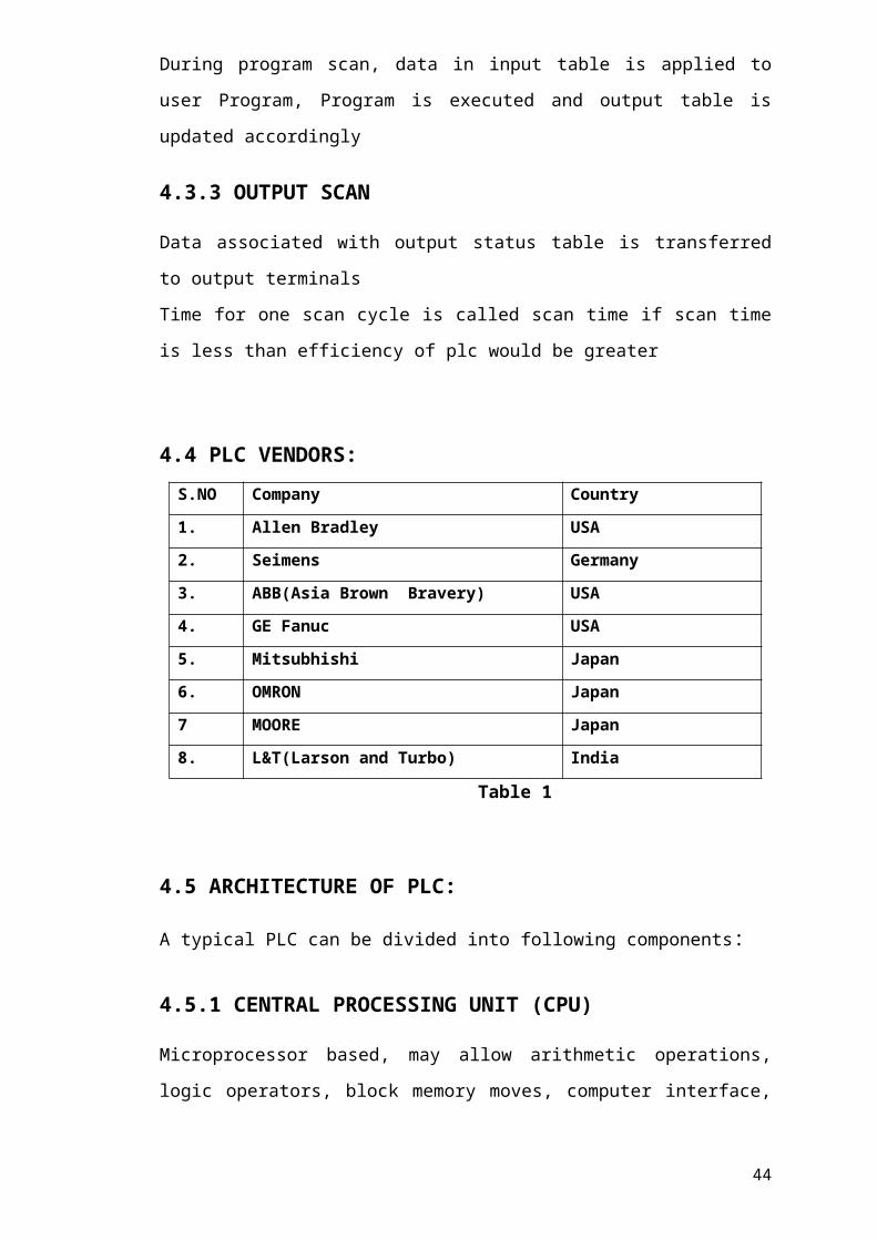
5.2 Allen Bradley micro logix 1000
Allen Bradley micro logix 1000 is the widely used plc now a day in industries. it is also one of the simplest plc which is use in the industries. It has six inputs and four outputs. It connected with pc with the help of serial communication wire. The connection of plc is established using software known as RS linx and the plc is programmed using software known as RS logix500. This plc also have timers, counters, compare blocks and mathematical logic.
Both these soft wares are developed by Rockwell Automation Corporation.
RSLinx Classic™ is the most widely installed communication server in automation today. RSLinx Classic provides plant-floor device connectivity for a wide variety of Rockwell Software applications such as RSLogix 5/500/5000 and RSView32. RSLinx Classic also provides open interfaces for third-party HMI, data collection and analysis packages, as well as custom client-applications. RSLinx Classic supports multiple software applications simultaneously, communicating to a variety of devices on many different Rockwell Automation Industrial networks.
You can communicate from anywhere to anywhere using RSLinx Classic. After selecting the appropriate drivers, RSLinx Classic allows you to browse your network for devices, just like you browse for files on your computer. The list of network types includes Ethernet, ControlNet, DeviceNet as well as legacy Rockwell Automation networks and protocols. Once you navigate to a device, right-click to access a variety of integrated configuration and monitoring tools.
Figure 5.1
5.2 IMPORTANT COMPONENTS
5.2.1 PUSH-BUTTONS
A push-button (also spelled pushbutton) or simply button is a simple switch mechanism for controlling some aspect of a machine or a process. Buttons are typically made out of hard material, usually plastic or metal. The surface is usually flat or shaped to accommodate the human finger or hand, so as to be easily depressed or pushed. Buttons are most often biased switches, though even many un-biased buttons (due to their physical nature) require
37

a spring to return to their un-pushed state. Different people use different terms for the "pushing" of the button, such as press, depress, mash, and punch.
In industrial and commercial applications, push buttons can be linked together by a mechanical linkage so that the act of pushing one button causes the other button to be released. In this way, a stop button can "force" a start button to be released. This method of linkage is used in simple manual operations in which the machine or process have no electrical circuits for control.
Pushbuttons are often color-coded to associate them with their function so that the operator will not push the wrong button in error. Commonly used colors are red for stopping the machine or process and green for starting the machine or process.
In industries basically two colors of push buttons are used these are red and green, here green stands for normally open (NO) and red stands for normally closed.
All these plc discussed above takes input from these push buttons these push buttons are used widely with almost all the plc.NO and NC push button basic diagram
Figure 5.2
Indicators are also widely used in automated factories or plants. They are used to indicate tings like if the motor is off green indicator is there and if the motor is on red indicator is there and for over load yellow is there. A basic indicator is shown below.
USE OF PUSHBUTTONS
The "push-button" has been utilized in calculators, push-button telephones, kitchen appliances, and various other mechanical and electronic devices, home and commercial.
In industrial and commercial applications, push buttons can be linked together by a mechanical linkage so that the act of pushing one button causes the other button to be
38

released. In this way, a stop button can "force" a start button to be released. This method of linkage is used in simple manual operations in which the machine or process have no electrical circuits for control.
Pushbuttons are often color-coded to associate them with their function so that the operator will not push the wrong button in error. Commonly used colors are red for stopping the machine or process and green for starting the machine or process.
WORKING OF PUSHBUTTON
a) NO PUSH BUTTON
A Normally Open (NO) Push Button is a push button that, in its default state, makes no electrical contact with the circuit. Only when the button is pressed down does it make electrical contact with the circuit.
39

Figure 5.3
When the button is pressed down, the switch makes electrical contact and the circuit is now closed. Therefore, electricity can now flow to the other part of the circuit connecting to the push button and make the device turn or power on the respective part.
Normally Open Push buttons are the most common type of push buttons used in devices and circuits.
b) NC PUSH BUTTON
A Normally Closed (NC) Push Button is a push button that, in its default state, makes electrical contact with the circuit.
40

Figure 5.4
When the button is pressed down, the switch no longer makes electrical contact and the circuit is now open. Therefore, electricity can no longer flow to the other part of the circuit to turn or power on the respective part of the circuit the button was made to switch.
Normally Closed Push buttons are not the most common type of push button used; Normally Open Push Buttons are. However, they still have widespread use and application in many devices.
5.2.2 INDICATOR
An instrument used to indicate the state or condition of an engine, furnace, electrical network, reservoir, or other physical system; a meter or gauge.
Figure 5.5
5.2.3 SENSORS
41

A sensor (also called detector) is convertor that measure a physical quantity and converts it into a signal which we can read by an observer or by an instrument. For example, mercury in glass thermometer converts the temperature into expansion and contraction of liquid which can be read on a calibrated glass tube. A thermocouple converts temperature to an output voltage which can be read by a voltmeter.
Sensors are used in everyday objects such as touch sensitive elevator buttons and lamps which dim or brighten by touching the base. There are also innumerable applications for sensor of which most people are never aware. An application includes cars, machines, aerospace medicines and robotics.
A sensor is a device which receives and responds to a signal when touched. A sensor’s sensitivity indicates how the sensor’s output changes when the measured quantity changes. For instance, if the mercury in the thermometer moves 1 cm then the temperature changes by 1 degree C, the sensitivity is 1 cm/ degree C.
A sensor that measure very small change must have very high sensitivity. Sensors also have an impact on what they measure. Sensor need to be designed to have all small effect on what is measured. Making the sensor smaller often improves this and may introduce other advantages.
5.3 CONNECTION OF OUTPUT WITH PLC
An output is not directly connected with plc. It has to be connected through relay or contactor, these are electromagnetic switching device or we use solid state relays(ssr). Using contactor or relays we can do remote on/off.
5.3.1 CONTACTOR
A contactor is an electrically controlled switch used for switching a power circuit, similar to a relay except with higher current ratings. A contactor is controlled by a circuit which has a much lower power level than the switched circuit.
Contactors come in many forms with varying capacities and features. Unlike a circuit breaker, a contractor is not intended to interrupt a short circuit current. Contactors range from those having a breaking current of several amperes to thousands of amperes and 24 V DC to many kilovolts. The physical size of contactors ranges from a device small enough to pick up with one hand, to large devices approximately a meter (yard) on a side.
Contactors are used to control electric motors, lighting, heating, capacitor banks, thermal evaporators, and other electrical loads.
A contactor has three components. The contacts are the current carrying part of the contactor. This includes power contacts, auxiliary contacts, and contact springs. The electromagnet (or "coil") provides the driving force to close the contacts.
42

The enclosure is a frame housing the contact and the electromagnet. Enclosures are made of insulating materials like Bakelite, Nylon 6, and thermosetting plastics to protect and insulate the contacts and to provide some measure of protection against personnel touching the contacts. Open-frame contactors may have a further enclosure to protect against dust, oil, explosion hazards and weather.
Magnetic blowouts use blowout coils to lengthen and move the electric arc. These are especially useful in DC power circuits. AC arcs have periods of low current, during which the arc can be extinguished with relative ease, but DC arcs have continuous high current, so blowing them out requires the arc to be stretched further than an AC arc of the same current.
OPERATING PRINCIPLE
Unlike general-purpose relays, contactors are designed to be directly connected to high-current load devices. Relays tend to be of lower capacity and are usually designed for both normally closed and normally open applications. Devices switching more than 15 amperes or in circuits rated more than a few kilowatts are usually called contactors. Apart from optional auxiliary low current contacts, contactors are almost exclusively fitted with normally open ("form A") contacts. Unlike relays, contactors are designed with features to control and suppress the arc produced when interrupting heavy motor currents.
When current passes through the electromagnet, a magnetic field is produced; this attracts the moving core of the contactor. The electromagnet coil draws more current initially, until its inductance increases when the metal core enters the coil. The moving contact is propelled by the moving core; the force developed by the electromagnet holds the moving and fixed contacts together. When the contactor coil is de-energized, gravity or a spring returns the electromagnet core to its initial position and opens the contacts.
For contactors energized with alternating current, a small part of the core is surrounded with a shading coil, which slightly delays the magnetic flux in the core. The effect is to average out the alternating pull of the magnetic field and so prevent the core from buzzing at twice line frequency.
Because arcing and consequent damage occurs just as the contacts are opening or closing, contactors are designed to open and close very rapidly; there is often an internal tipping point mechanism to ensure rapid action.
Rapid closing can, however, lead to increase contact bounce which causes additional unwanted open-close cycles. One solution is to have bifurcated contacts to minimize contact bounce; two contacts designed to close simultaneously, but bounce at different times so the circuit will not be briefly disconnected and cause an arc.
5.3.2 RELAY
43
A relay is an electrically operated switch. Many relays use an electromagnet to operate a switching mechanism mechanically, but other operating principles are also used. Relays are used where it is necessary to control a circuit by a low-power signal (with complete electrical isolation between control and controlled circuits), or where several circuits must be controlled by one signal. The first relays were used in long distance telegraph circuits, repeating the signal coming in from one circuit and re-transmitting it to another. Relays were used extensively in telephone exchanges and early computers to perform logical operations.
A type of relay that can handle the high power required to directly control an electric motor or other loads is called a contactor. Solid-state relays control power circuits with no moving parts, instead using a semiconductor device to perform switching. Relays with calibrated operating characteristics and sometimes multiple operating coils are used to protect electrical circuits from overload or faults; in modern electric power systems these functions are performed by digital instruments still called "protective relays".
Figure 5.6
A simple electromagnetic relay consists of a coil of wire wrapped around a soft iron core, an iron yoke which provides a low reluctance path for magnetic flux, a movable iron armature, and one or more sets of contacts (there are two in the relay pictured). The armature is hinged to the yoke and mechanically linked to one or more sets of moving contacts. It is held in place by a spring so that when the relay is de-energized there is an air gap in the magnetic circuit. In this condition, one of the two sets of contacts in the relay pictured is closed, and the other set is open. Other relays may have more or fewer sets of contacts depending on their function. The relay in the picture also has a wire connecting the armature to the yoke. This ensures continuity of the circuit between the moving contacts on the armature, and the circuit track on the printed circuit board (PCB) via the yoke, which is soldered to the PCB.
When an electric current is passed through the coil it generates a magnetic field that activates the armature and the consequent movement of the movable contact either makes or breaks (depending upon construction) a connection with a fixed contact. If the set of contacts was closed when the relay was de-energized, then the movement opens the contacts and breaks the connection, and vice versa if the contacts were open. When the current to the coil is switched off, the armature is returned by a force, approximately half as strong as the magnetic force, to its relaxed position. Usually
44

this force is provided by a spring, but gravity is also used commonly in industrial motor starters. Most relays are manufactured to operate quickly. In a low-voltage application this reduces noise; in a high voltage or current application it reduces arcing.
When the coil is energized with direct current, a diode is often placed across the coil to dissipate the energy from the collapsing magnetic field at deactivation, which would otherwise generate a voltage spike dangerous to semiconductor circuit components. Some automotive relays include a diode inside the relay case. Alternatively, a contact protection network consisting of a capacitor and resistor in series (snubber circuit) may absorb the surge. If the coil is designed to be energized with alternating current (AC), a small copper "shading ring" can be crimped to the end of the solenoid, creating a small out-of-phase current which increases the minimum pull on the armature during the AC cycle.
A solid-state relay uses a thyristor or other solid-state switching device, activated by the control signal, to switch the controlled load, instead of a solenoid. An optocoupler (a light-emitting diode (LED) coupled with a photo transistor) can be used to isolate control and controlled circuits.
5.3.3 SOLID-STATE RELAY (SSR)
A solid-state relay (SSR) is an electronic switching device in which a small control signal controls a larger load current or voltage. It consists of a sensor which responds to an appropriate input (control signal), a solid-state electronic switching device which switches power to the load circuitry, and some coupling mechanism to enable the control signal to activate this switch without mechanical parts. The relay may be designed to switch either AC or DC to the load. It serves the same function as an electromechanical relay, but has no moving parts.
Figure 5.7
The control signal must be coupled to the controlled circuit in a way which isolates the two circuits electrically.
45

Many SSRs use optical coupling. The control voltage energizes an LED which illuminates and switches on a photo-sensitive diode (photo-voltaic); the diode current turns on a back-to-back thyristor, silicon controlled rectifier, or MOSFET to switch the load. The optical coupling allows the control circuit to be electrically isolated from the load
A SSR based on a single MOSFET, or multiple MOSFETs in a paralleled array, works well for DC loads.
MOSFETs have an inherent substrate diode that conducts in the reverse direction, so a single MOSFET cannot block current in both directions. For AC (bi-directional) operation two MOSFETs are arranged back to back with their source pins tied together. Their drain pins are connected to either side of the output. The substrate diodes are alternately reverse biased to block current when the relay is off. When the relay is on, the common source is always riding on the instantaneous signal level and both gates are biased positive relative to the source by the photo-diode.
5.3.4 OLR (OVERLOAD RELAY)
A relay that opens a circuit when the load in the circuit exceeds a preset value, in order to provide overload protection; usually responds to excessive current, but may respond to excessive values of power, temperature, or other quantities. Also known as overload relay.
A relay in the circuit of a motor which causes the motor to be disconnected from its source of power if the current to the motor exceeds a predetermined value.
5.3.5 MINIATURE CIRCUIT BREAKER (MCB)
46

Figure 5.8
There are two arrangement of operation of miniature circuit breaker. One due to thermal effect of over current and other due to electromagnetic effect of over current. The thermal operation of miniature circuit breaker is achieved with a bimetallic strip whenever continuous over current flows through MCB; the bimetallic strip is heated and deflects by bending. This deflection of bimetallic strip releases mechanical latch. As this mechanical latch is attached with operating mechanism, it causes to open the miniature circuit breaker contacts. But during short circuit condition, sudden rising of electric current, causes electromechanical displacement of plunger associated with tripping coil or solenoid of MCB. The plunger strikes the trip lever causing immediate release of latch mechanism consequently open the circuit breaker contacts. This was a simple explanation of miniature circuit breaker working principle.Miniature circuit breaker construction is very simple, robust and maintenance free. Generally an MCB is not repaired or maintained, it just replaced by new one when required.
5.4 RELAY TYPE INSTRUCTION
The relay-type instructions are the most basic of programmable controller
instructions. They provide the same capabilities as hardwired relay logic, but with
greater flexibility. These instructions have the ability to examine the ON/OFF status
of a specific bit addressed in memory and to control the state of an internal or external
output bit. The following relay-type instructions are the most commonly available in
any controller that has a ladder diagram instruction set.
47

5.4.1 NORMALLY OPEN CONTACT
The normally open contact is programmed when the presence of the input signal is
needed to turn an output ON. When evaluated, the referenced address is examined for
an ON (1) condition. The reference address may contains the status of an external
input, external output, or internal output. During the examination, if the reference
address is ON, then the normal open contact will close and permit logic continuity
(power flow). If it is OFF (0), then the normally open contact will assume its normally
programmed state (open), thus breaking logic continuity.
Figure 5.9
5.4.2 NORMALLY CLOSED CONTACT
The normally closed contact is working as opposite to the normally open contact. It is
programmed when the absence of the referenced signal is needed to turn an output
ON (1). The reference address is examined for an OFF (0) condition. If the address is
OFF, then the normally closed contact will remain closed, allowing logic continuity.
When it is ON, the contact will open and break logic continuity.
Figure 5.10
5.4.3 BRANCH START
The branch start instruction begins each parallel logic branch of a rung. It is the first
instruction programmed if a parallel branch or logical OR functions is needed in a
logic rung.
Figure 5.11
48

5.4.4 BRANCH END
The branch end instruction finishes a set of parallel branches. This instruction is used
after the last instruction of the last branch to complete a set of parallel branches.
Figure 5.12
5.4.5 ENERGIZE COIL ( )
The energize coil instruction is programmed to control either an output connected to
the controller, or an internal output bit. If any rung path has logic continuity, the
referenced output is turned ON. The output is turned OFF if logic continuity is lost.
When the output is ON, a normally opened contact of the same address will close, and
a normally closed contact will open. If the output goes OFF, any normally opened set
of contacts will then open, and normally closed contacts will close. An example is
shown (figure 3) to illustrate the rung relay-type instructions. Either of the input is
true, the output will be true.
Figure 5.13
5.4.6 LATCH COIL AND UNLATCH COIL (L) (U)The latch coil instruction is programmed, for an output to remain energized (if
necessary) even though the status of the input bits that caused the output to energize
may change. If any rung path has logic continuity, the output is turned ON and
retained ON even if logic continuity or system power is lost. The latched output will
remain latched ON until it is unlatched by an output instruction of the same reference
address. The unlatch instruction is the only automatic (programmed) means of
resetting the latched output. Although most controllers allow latching of internal or
external outputs, some are restricted to latching internal outputs only.
49

Figure 5.14
5.4.7 Timers
Timers are devices that count increments of time. Traffic lights are one example where timers are used. In this example timers are used to control the length of time between signal changes.
Figure 5.15Timers are represented by boxes in ladder logic. When a timer receives an enable, the timer starts to time. The timer compares its current time with the preset time. The output of the timer is a logic 0 as long as the current time is less than the preset time. When the current time is greater than the preset time the timer output is a logic 1.slc500 uses three types of timers: On-Delay (TON), Retentive On-Delay (TONR), and Off-Delay (TOF).
Figure 5.16
50

S7-200 Timers S7-200 timers are provided with resolutions of 1 millisecond, 10 milliseconds, and 100 milliseconds. The maximum value of these timers is 32.767 seconds, 327.67 seconds, and 3276.7 seconds, respectively. By adding program elements, logic can be programmed for much greater time intervals.
Hard-Wired Timing Circuit Timers used with PLCs can be compared to timing circuits used in hard-wired control line diagrams. In the following example, a normally open (NO) switch (S1) is used with a timer (TR1). For this example the timer has been set for 5 seconds. When S1 is closed, TR1 begins timing. When 5 seconds have elapsed, TR1 will close its associated normally open TR1 contacts, illuminating pilot light PL1. When S1 is open, deenergizing TR1, the TR1 contacts open, immediately extinguishing PL1. This type of timer is referred to as ON delay. ON delay indicates that once a timer receives an enable signal, a predetermined amount of time (set by the timer) must pass before the timer’s contacts change
Figure 5.17
On-Delay (TON) When the On-Delay timer (TON) receives an enable (logic 1) at its input (IN), a predetermined amount of time (preset time - PT) passes before the timer bit (T-bit) turns on. The T-bit is a logic function internal to the timer and is not shown on the symbol. The timer resets to the starting time when the enabling input goes to logic 0.
51

Figure 5.18
Figure 5.19A small sample of the flexibility of PLCs is shown in the following program logic in figure5.19. By reprogramming the T37 contact as a normally closed contact, the function of the circuit is changed to cause the indicator light to turn off only when the timer times out. This function change was accomplished without changing or rewiring I/O devices.
Figure 5.20
52

Retentive On-Delay (TONR) The Retentive On-Delay timer (TONR) functions in a similar manner to the On-Delay timer (TON). There is one difference .The Retentive On-Delay timer times as long as the enabling input is on, but does not reset when the input goes off. The timer must be reset with a RESET (R) instruction.
Figure 5.21The same example used with the On-Delay timer will be used with the Retentive On-Delay timer. When the switch is closed at input I0.3, timer T5 (Retentive timer) begins timing. If, for example, after 10 seconds input I0.3 is opened the timer stops. When input I0.3 is closed the timer will begin timing at 10 seconds. The light will turn on 5 seconds after input I0.3 has been closed the second time. A RESET (R) instruction can be added. Here a pushbutton is connected to input I0.2. If after 10 seconds input I0.3 were opened, T5 can be reset by momentarily closing input I0.2. T5 will be reset to 0 and begin timing from 0 when input I0.3 is closed again.
Figure 5.22
Off-Delay (TOF) The Off-Delay timer is used to delay an output off for a fixed period of time after the input turns off. When the enabling bit turns on the timer bit
53
turns on immediately and the value is set to 0. When the input turns off, the timer counts until the preset time has elapsed before the timer bit turns off.
Figure 5.23S7-200 Timers The S7-200s have 256 timers. The specific T number chosen for the timer determines its time base and whether it is TON,TONR, or TOF.
54

Timer Example In the following example a tank will be filled with two chemicals, mixed, and then drained. When the Start Button is pressed at input I0.0, the program starts pump 1 controlled by output Q0.0. Pump 1 runs for 5 seconds, filling the tank with the first chemical, then shuts off. The program then starts pump 2, controlled by output Q0.1. Pump 2 runs for 3 seconds filling the tank with the second chemical. After 3 seconds pump 2 shuts off. The program starts the mixer motor, connected to output Q0.2 and mixes the two chemicals for 60 seconds. The program then opens the drain valve controlled by output Q0.3, and starts pump 3 controlled by output Q0.4. Pump 3 shuts off after 8 seconds and the process stops. A manual Stop switch is also provided at input I0.1.
Figure 5.24
55

5.4.8 COUNTERS
Counters used in PLCs serve the same function as mechanical counters. Counters compare an accumulated value to a preset value to control circuit functions. Control applications that commonly use counters include the following:
• Count to a preset value and cause an event to occur
• Cause an event to occur until the count reaches a preset value
A bottling machine, for example, may use a counter to count bottles into groups of six
for packaging.
Figure 5.25
Counters are represented by boxes in ladder logic. Counters increment/decrement one count each time the input transitions from off (logic 0) to on (logic 1). The counters are reset when a RESET instruction is executed. S7-200 uses three types of counters: up counter (CTU), down counter (CTD), and up/down counter (CTUD).
Figure 5.26S7-200 Counters There are 256 counters in the S7-200, numbered C0 through C255. The same number cannot be assigned to more than one counter. For example, if an up counter is assigned number 45, a down counter cannot also be assigned number 45. The maximum count value of a counter is ±32,767.
56

Up Counter The up counter counts up from a current value to a preset value (PV). Input CU is the count input. Each time CU transitions from logic 0 to logic 1 the counter increments by a count of 1. Input R is the reset. A preset count value is stored in PV input. If the current count is equal to or greater than the preset value stored in PV, the output bit (Q) turns on (not shown).
Down Counter The down counter counts down from the preset value (PV) each time CD transitions from logic 0 to logic 1. When the current value is equal to zero the counter output bit (Q) turns on (not shown). The counter resets and loads the current value with the preset value (PV) when the load input (LD) is enabled.
Up/Down Counter The up/down counter counts up or down from the preset value each time either CD or CU transitions from logic 0 to logic 1.When the current value is equal to the preset value, the output QU turns on. When the current value (CV) is equal to zero, the output QD turns on. The counter loads the current value (CV) with the preset value (PV) when the load input (LD) is enabled. Similarly, the counter resets and loads the current value (CV) with zero when the reset (R) is enabled. The counter stops counting when it reaches preset or zero.
5.4.9 ARITHEMATIC OPERATIONS
Addition, subtraction, multiplication, and division are the four basic operations
included in the arithmetic operations. These instructions use the contents of two word
locations and perform the desired function. The add and subtract instructions use one
word. Multiply and divide need two words for the computed result.
A) ADDITION (ADD) (+)
The ADD instruction performs the addition of two values stored in two different
memory locations. The processor uses a GET (data transfer) instruction to access the
two values. The result is stored in the word address referenced by the ADD coil. The
input conditions should be programmed before the values are accessed in the addition
rung, if the addition operation is enabled only when the rung conditions are true.
57

Figure 5.26
B) SUBTRACTION (SUB) (-)It performs the subtraction operation of two registers. As in addition, if there is a
condition to enable the subtraction, it should be programmed before the values are
accessed in the rung. The subtraction result register will use a minus sign to represent
a negative result.
Figure 5.27
C) MULTIPLICATION (MUL) Multiplication operation is performed when MUL is defined. It uses two registers to
hold the results of the operation between two operand registers. The two registers are
referenced by two output coils. It should be programmed before the two operands are
accessed in the multiplication rung, if there is a condition to enable the operation.
Figure 5.28
D) DIVIDE (DIV) The DIV instruction performs the quotient calculations of two numbers. The result of
the division is held in two result registers as referenced by the output coils. The first
register generally holds the integer, while the second result register holds the decimal
fraction.
58

Figure 5.29
5.4.10 DATA COMPERISON OPERATIONS
The manipulation of data using ladder diagram instructions, generally involves simple
register (word) operations to compare the contents of two registers. In the ladder
language, there are three basic data comparison instructions: equal to, greater than,
and less than. Based on the result of a greater than, less than, or equal to comparison,
an output can be turned ON or OFF, or more other operation can be performed.
A) EQUAL TO (==)
The equal to instruction is used to compare the contents of two referenced registers
for an equal condition, when the rung conditions are true. If the operation is true, the
output coil is energized.
Figure 5.30
B) LESS THEN (<)
The less instruction compares the contents of the value of one register to the value
stored in second register. If the test condition is true (i.e less than), the output coil is
energized.
59

Figure 5.31
C) GREATER THAN (>)
Greater than instruction operates the same way as the less than instruction, except it
test for greater than condition. Some controllers do not have this function, because a
greater than" function can perform using the "less than" logic by reversing the order
of the data and the "less than" function in the logic rung.
Figure 5.32
D) JUMP (JMP)
The jump instruction allows the CPU to jump to a new position in the ladder diagram
from the normal sequential execution. If the jump logic rung is true, the jump coil
(JMP) instructs the CPU to jump to and execute the rung labeled with the same
reference address as the jump coil. This allows the program to execute rungs out of
the normal sequential flow of a standard ladder program.
E) LANEL [LBL]
The label (LBL) is to identify that ladder rung which is the destination of a jump
instruction. The label reference must match that of the jump instruction with which it
is used. The label in6struction does not contribute to logic continuity, and it is always
logically true. It is placed as the6 first logic condition in the rung. A label instruction
referenced by a unique address can be defined only once in a program.
60

F) RETURN (RET)
The RET instruction is used to terminate a ladder jump subroutine. It must be used at
the end of each subroutine.
5.5 SINKING-SOURCING CONCEPT
5.5.1 SINKING
The current driving capability of a circuit, to draw a current toward the ground or
zero voltage, or to a lower voltage.
5.5.2 SOURCING
The current driving capability of a circuit, to draw a current from the power supply or
the higher voltage in the circuit.
Most commonly used DC module options in PLCs are:
1. Sinking input and
2. Sourcing output module
Figure 5.33
Sinking I/O circuits on the I/O modules receive (sink) current from sourcing field
devices. Sinking output modules used for interfacing with electronic equipment.
61

PLC has input and output lines through which it is connected to a system it directs.
Input can be keys, switches, sensors while outputs are led to different devices from
simple signalization lights to complex communication modules.
This is a very important part of the story about PLC controllers because it directly
influences what can be connected and how it can be connected to controller inputs or
outputs. Two terms most frequently mentioned when discussing connections to inputs
or outputs are "sinking" and "sourcing". The most brief definition of these two
concepts would be:
SINKING = Common GND line (-)
SOURCING = Common VCC line (+)
5.5.3 ALLEN BRADLEY DATA FILE DESCRIPTION
File # Type Description
O0 Output This file stores the state of output terminals for the
controller.
I1 Input This file stores the state of input terminals for the controller.
S2 Status This file stores controller operation information useful for
troubleshooting controller and program operation.
B3 Bit This file stores internal relay logic.
T4 Timer This file stores the timer accumulator and preset values and
status bits.
C5 Counter This file stores the counter accumulator and preset values
and status bits.
R6 Control This file stores the length, pointer position, and status bits
for control instructions such as shift registers and
sequencers.
N7 Integer This file is used to store bit information or numeric values
with a range of -32767 to 32768.
62

5.6 LADDER LOGIC EXAMPLES
5.6.1 SEQUENTIALLY OPERATING THREE MOTORS WITH
DELAY BY USING TIMER
Problem consists of one push button (NO Type), three TON Timers and three outputs.
Which have to be operated in following sequence:
When push button is pressed then timer 1 starts and output 1 run for 10 sec. after
completion of 10 sec. timer 2 start and output 2 run for 20 sec. after that timer 2 stops
and timer 3 start so output 3 run for 25 sec. again the process start with same
sequence. when push button is released then all timer reset and whole process gets
stops.
Figure 5.34
63

5.6.2 SEQUENTIALLY TURN OFF THE THREE OUTPUTS BY
USING TIMER AND LESS THAN INSTRUCTION
Problem consists of one push button (NO Type), One TON Timers, Three less than
instruction and three outputs. Which have to be operated in following sequence:
When push button is pressed then timer starts and all three output run. 1 Output stops
after 10 sec. duration. 2 output stop after 15 sec. Duration 3 output stop after 20 sec.
duration. Again the process starts with same sequence. When push button is released
then all timer reset and whole process gets stops.
Figure 5.35
64

Chapter – 6
SIEMENS PLC
6.1 INTRODUCTION
Siemens AG (German pronunciation: [ˈziːmɛns]) is a German multinational conglomerate company headquartered in Berlin and Munich. It is the largest engineering company in Europe. The principal divisions of the company are Industry, Energy, Healthcare, and Infrastructure & Cities, which represent the main activities of the company. The company is a prominent maker of medical diagnostics equipment and its medical health care division, which generates about 12 percent of the company's total sales, is its second most profitable unit, after the industrial automation division.Siemens and its subsidiaries employ approximately362, 000 people worldwide and reported global revenue of around €71.9 billion in 2014accordingto their annual report.
6.2 Software section
6.2.1 Introduction
The Totally Integrated Automation Portal, referred to as TIA Portal in the following, offers all the functions you need for implementing your automation task assembled in a single, cross software platform.
The TIA Portal is the first shared working environment for integrated engineering with the various SIMATIC systems made available within a single framework. The TIA Portal therefore also enables reliable, convenient cross-system collaboration for the first time.
All required software packages, from hardware configuration and programming to visualization of the process is integrated in a comprehensive engineering framework.
6.2.2 Creating a project
a) Introduction
In the following step, you will create a new project.
All data which is generated during the creation of an automation solution is saved in the project file. The data is stored in the form of objects. Within the project, the objects are arranged in a tree structure (project hierarchy).
The project hierarchy is based on the devices and stations along with the configuration data and programs belonging to them.
65

b) Requirement
You need the following hardware and software equipment to create the project:
● Hardware:
– The CPU 1511-1 PN that was installed and wired in the hardware section of the Getting Started.
– An Ethernet connection to your programming device/PC.
● Software:
The following software packages must be installed and executable on your programming device/PC:
– SIMATIC STEP 7 Professional V13
– SIMATIC WinCC Advanced V13 or SIMATIC WinCC Professional V13
c) Creating a new project
To create a new project, follow these steps:
1. Click "Create new project".
2. Enter a name for your project.
d) Creating an s7-1200 CPU
Introduction
In the following step, you will create an unspecified CPU. Unspecified CPUs are placeholders for specific CPUs from the hardware catalog which will be defined later.
Procedure
1. Open the "Devices & Networks" portal.
2. Insert a new device.
3. Enter "Color_Mixing_CPU" as the name for the CPU.
4. Open the "SIMATIC S7-1200" folder.
5. Select the CPU which has not yet been specified
66
6.2.3 Running the hardware detection
Introduction
In the following section, you will use the hardware detection function to read the CPU type.
Run an LED flashing test during hardware detection. The LED flashing test activates the LEDs on a detected device. You may also use this function to verify that the correct device was selected in a hardware configuration consisting of several devices.
Procedure
1. Select the unspecified CPU in the project tree.
2. Select the "Hardware detection" function from the "Online" menu.
Option 2: Click on the yellow framed alarm in the device view.
3. Select the "PN/IE" entry as the type of PG/PC interface.
4. Select the PG/PC interface.
5. Click the "Show all compatible devices" option.
6. Select the CPU from the compatible devices in the subnet.
7. Select the "Flash LED" check box to run a flashing test.
8. Click "Detect" to replace the unspecified CPU with the necessary CPU type.
6.2.4 PROCEDURE: Create a project
Working with STEP 7 is easy! See how quickly you can get started with creating a project:
67

In the Start portal, click the "Create new project" task. Enter a project name and click the "Create" button.
Figure 6.2
After creating the project, select the Devices & Networks portal.
Click the "Add new device" task.
Figure 6.3
Select the CPU to add to the project:
1. In the "Add new device" dialog, click the "SIMATIC PLC" button.
2. Select a CPU from the list.
3. To add the selected CPU to the project, click the "Add" button.
Note that the "Open device view" option is selected. Clicking "Add" with this option selected opens the "Device configuration" of the Project view. The Device view displays the CPU that you added.
68
Figure 6.1

Your program code consists of instructions that the CPU executes in sequence. For this example, use ladder logic (LAD) to create the program code. The LAD program is a sequence of networks that resemble the rungs of a ladder.
To open the program editor, follow these steps:
1. Expand the "Program blocks" folder in the Project tree to display the "Main [OB1]" block.
2. Double-click the "Main [OB1]" block. The program editor opens the program block (OB1).
Use the buttons on the "Favorites" to insert contacts and coils onto the network.
Figure 6.4
Now create a simple network in your user program
1. Click the "Normally open contact" button on the "Favorites" to add a contact to the network.
2. For this example, add a second contact.
3. Click the "Output coil" button to insert a coil
Figure 6.5
1. Select the left rail to select the rail for the branch.
2. Click the "Open branch" icon to add a branch to the rail of the network.
69

Figure 6.6
3. Insert another normally open contact to the open branch.
Figure 6.7
4. Drag the double-headed arrow to a connection point (the green square on the rung) between the two contacts on the first rung.
To save the project, click the "Save project" button in the toolbar. Notice that you do not have to finish editing the rung before saving. You can now associate the tag names with these instructions.
Chapter -7
70

DRIVES
7.1 Variable Frequency Drive (VFD)
A Variable Frequency Drive is used for applications where in speed control is of an essential importance due to load changes wherein the speed needs to be increased or decreased accordingly. Traditional methods in existence have addressed this issue, each with their own drawbacks such as high motor starting current, lower power factor, energy losses, etc. A variable frequency drive (VFD) (also termed Adjustable frequency drive, variable speed drive, AC drive, micro drive or inverter drive) is a type of adjustable speed drive used in electromechanical drive systems to control AC motor speed and torque by varying motor input frequency and voltage. VFDs are used in applications ranging from small appliances to the largest of mine mill drives and compressors. However, around 25% of the world's electrical energy is consumed by electric motors in industrial applications, which are especially conducive for energy savings using VFDs in centrifugal load service, and VFDs' global market penetration for all applications is still relatively small. That lack of penetration highlights significant energy efficiency improvement opportunities for retrofitted and new VFD installations.Over the last four decades, power electronics technology has reduced VFD cost and size and has improved performance through advances in semiconductor switching devices, drive topologies, simulation and control techniques, and control hardware and software.VFDs are available in a number of different low and medium voltage AC-AC and DC -AC topologies.
7.2 Variable Frequency Drive with PLC and SCADA
Programmable Logic Controller (PLC) and Supervisory Control And Data Acquisition (SCADA) are two new approaches to control a Variable Frequency Drive (VFD) whose output is fed to a three-phase induction motor and driving a conveyor belt. The conveyor belt has three sensors are inputs which senses a passing object and carries out the necessary instructions programmed in ladder logic programming of the PLC through the medium of a personal computer (PC).
The SCADA software installed in the PC in turn enables the human operator to control the entire operation away from the plant and just by using the virtual inputs designated on his computer screen. The results have been verified with a validating experiment
7.3 Allen-Bradley PowerFlex 4M
71

Figure 7.1 Allen-Bradley PowerFlex 4M
The Allen-Bradley PowerFlex 4M AC drives are the smallest and most cost-effective members of the PowerFlex family of drives. Available in power ratings from 0.2 to 11 kW (0.25 to 15 HP) and in voltage classes of 120, 240, 480 and 600 volts, PowerFlex 4M are designed to meet global OEM and end-user demands for flexibility, space savings, ease of use and are cost-effective alternatives for speed control of applications such as machine tools, fans, pumps and conveyors and material handling systems.
7.4 Starts Up, Programming and Operation• An integral keypad provides out of the box operation using the local potentiometer and control keys.• The 12 most common application parameters are contained in the Basic Program Group, making programming fast and easy.• The programming keys have the same function as all other PowerFlex drives, so if you can program one PowerFlex drive, you can program them all.• 4 digit display with 10 additional LED indicators provides an intuitive display of drive status and information.• Integral RS-485 communications can be used for programming from a PC. It can also be used in a multi-drop network configuration. A serial converter module provides connectivity to any controller with a DF1 port.• A NEMA/UL Type 4X remote and NEMA/UL Type 1 hand-held LCD keypad provide additional programming and control flexibility, both featuring the popular Copy Cat function.
72

Figure 7.2
7.5 IMPORTANT WIRINGS
1) POWER WIRING
Figure 7.3
73

Figure 7.4
7.6 PANEL INSTRUCTIONS
The interface module is shown above and a menu structure is shown below, to navigate through the menu structure you must do the following
74

75

7.7 List of basic parameters to set up drive for use
7.8 ADVANTAGES OF AC DRIVES:
1. AC drives provide the most energy efficient means of capacity control.
2. AC drives have the lowest starting current of any starter type.
3. AC drives reduce thermal and mechanical stresses on motors and belts.
76

4. AC drive installation is as simple as connecting the power supply to the AC drive.
5. AC drives with AFE technology can meet even the most stringent harmonic standards and reduce
6. Backup generator sizing.
7. AC drives provide high power factor, eliminating the need for external power factor correction capacitors.
8. AC drives provide lower KVA, helping alleviate voltage sags and power outages.
7.9 APPLICATION AREAS
AC drive usage has increased dramatically in HVAC applications. The AC drives are now commonly applied to air handlers, pumps, chillers and tower fans. A better understanding of AC drives will lead to improved application and selection of both equipment and HVAC systems.
77

Chapter - 8
CONCLUSION
In my two months of training I acquired knowledge about automation industries and how work in industries. During this time I learnt about the programming in automation. I got some information about plc and how we work on it. I learned the programming on different plc by using different plc software’s.
I also learnt about basics of scada and how it useful in industries. I also learnt about connection of plc and scada through contactors and relay. I also got brief knowledge about drives.
Companies that dealing with automation industries using plc and scada needs a that type of employees .so the knowledge that I got during my training is helpful in future for employment.
78

Bibliography
www.google.com
www.wikipedia.com
www.rockwell.com
www.plcmanual.com
www.plc.net
www.Automation.com
79

THANK YOU
80